EP3450689B1 - Gas turbine engine having a fan hub attachment and securing method therefor - Google Patents
Gas turbine engine having a fan hub attachment and securing method therefor Download PDFInfo
- Publication number
- EP3450689B1 EP3450689B1 EP18191573.7A EP18191573A EP3450689B1 EP 3450689 B1 EP3450689 B1 EP 3450689B1 EP 18191573 A EP18191573 A EP 18191573A EP 3450689 B1 EP3450689 B1 EP 3450689B1
- Authority
- EP
- European Patent Office
- Prior art keywords
- hub
- fan
- attachment features
- gas turbine
- turbine engine
- Prior art date
- Legal status (The legal status is an assumption and is not a legal conclusion. Google has not performed a legal analysis and makes no representation as to the accuracy of the status listed.)
- Active
Links
Images






Classifications
-
- F—MECHANICAL ENGINEERING; LIGHTING; HEATING; WEAPONS; BLASTING
- F01—MACHINES OR ENGINES IN GENERAL; ENGINE PLANTS IN GENERAL; STEAM ENGINES
- F01D—NON-POSITIVE DISPLACEMENT MACHINES OR ENGINES, e.g. STEAM TURBINES
- F01D5/00—Blades; Blade-carrying members; Heating, heat-insulating, cooling or antivibration means on the blades or the members
- F01D5/30—Fixing blades to rotors; Blade roots ; Blade spacers
- F01D5/3053—Fixing blades to rotors; Blade roots ; Blade spacers by means of pins
-
- B—PERFORMING OPERATIONS; TRANSPORTING
- B64—AIRCRAFT; AVIATION; COSMONAUTICS
- B64C—AEROPLANES; HELICOPTERS
- B64C11/00—Propellers, e.g. of ducted type; Features common to propellers and rotors for rotorcraft
- B64C11/02—Hub construction
- B64C11/04—Blade mountings
-
- B—PERFORMING OPERATIONS; TRANSPORTING
- B64—AIRCRAFT; AVIATION; COSMONAUTICS
- B64C—AEROPLANES; HELICOPTERS
- B64C11/00—Propellers, e.g. of ducted type; Features common to propellers and rotors for rotorcraft
- B64C11/02—Hub construction
- B64C11/04—Blade mountings
- B64C11/08—Blade mountings for non-adjustable blades
-
- F—MECHANICAL ENGINEERING; LIGHTING; HEATING; WEAPONS; BLASTING
- F04—POSITIVE - DISPLACEMENT MACHINES FOR LIQUIDS; PUMPS FOR LIQUIDS OR ELASTIC FLUIDS
- F04D—NON-POSITIVE-DISPLACEMENT PUMPS
- F04D29/00—Details, component parts, or accessories
- F04D29/26—Rotors specially for elastic fluids
- F04D29/32—Rotors specially for elastic fluids for axial flow pumps
- F04D29/321—Rotors specially for elastic fluids for axial flow pumps for axial flow compressors
- F04D29/322—Blade mountings
-
- F—MECHANICAL ENGINEERING; LIGHTING; HEATING; WEAPONS; BLASTING
- F02—COMBUSTION ENGINES; HOT-GAS OR COMBUSTION-PRODUCT ENGINE PLANTS
- F02C—GAS-TURBINE PLANTS; AIR INTAKES FOR JET-PROPULSION PLANTS; CONTROLLING FUEL SUPPLY IN AIR-BREATHING JET-PROPULSION PLANTS
- F02C7/00—Features, components parts, details or accessories, not provided for in, or of interest apart form groups F02C1/00 - F02C6/00; Air intakes for jet-propulsion plants
- F02C7/04—Air intakes for gas-turbine plants or jet-propulsion plants
-
- F—MECHANICAL ENGINEERING; LIGHTING; HEATING; WEAPONS; BLASTING
- F05—INDEXING SCHEMES RELATING TO ENGINES OR PUMPS IN VARIOUS SUBCLASSES OF CLASSES F01-F04
- F05D—INDEXING SCHEME FOR ASPECTS RELATING TO NON-POSITIVE-DISPLACEMENT MACHINES OR ENGINES, GAS-TURBINES OR JET-PROPULSION PLANTS
- F05D2220/00—Application
- F05D2220/30—Application in turbines
- F05D2220/36—Application in turbines specially adapted for the fan of turbofan engines
-
- F—MECHANICAL ENGINEERING; LIGHTING; HEATING; WEAPONS; BLASTING
- F05—INDEXING SCHEMES RELATING TO ENGINES OR PUMPS IN VARIOUS SUBCLASSES OF CLASSES F01-F04
- F05D—INDEXING SCHEME FOR ASPECTS RELATING TO NON-POSITIVE-DISPLACEMENT MACHINES OR ENGINES, GAS-TURBINES OR JET-PROPULSION PLANTS
- F05D2250/00—Geometry
- F05D2250/10—Two-dimensional
- F05D2250/13—Two-dimensional trapezoidal
- F05D2250/131—Two-dimensional trapezoidal polygonal
-
- F—MECHANICAL ENGINEERING; LIGHTING; HEATING; WEAPONS; BLASTING
- F05—INDEXING SCHEMES RELATING TO ENGINES OR PUMPS IN VARIOUS SUBCLASSES OF CLASSES F01-F04
- F05D—INDEXING SCHEME FOR ASPECTS RELATING TO NON-POSITIVE-DISPLACEMENT MACHINES OR ENGINES, GAS-TURBINES OR JET-PROPULSION PLANTS
- F05D2250/00—Geometry
- F05D2250/10—Two-dimensional
- F05D2250/13—Two-dimensional trapezoidal
- F05D2250/132—Two-dimensional trapezoidal hexagonal
-
- F—MECHANICAL ENGINEERING; LIGHTING; HEATING; WEAPONS; BLASTING
- F05—INDEXING SCHEMES RELATING TO ENGINES OR PUMPS IN VARIOUS SUBCLASSES OF CLASSES F01-F04
- F05D—INDEXING SCHEME FOR ASPECTS RELATING TO NON-POSITIVE-DISPLACEMENT MACHINES OR ENGINES, GAS-TURBINES OR JET-PROPULSION PLANTS
- F05D2250/00—Geometry
- F05D2250/20—Three-dimensional
- F05D2250/23—Three-dimensional prismatic
-
- F—MECHANICAL ENGINEERING; LIGHTING; HEATING; WEAPONS; BLASTING
- F05—INDEXING SCHEMES RELATING TO ENGINES OR PUMPS IN VARIOUS SUBCLASSES OF CLASSES F01-F04
- F05D—INDEXING SCHEME FOR ASPECTS RELATING TO NON-POSITIVE-DISPLACEMENT MACHINES OR ENGINES, GAS-TURBINES OR JET-PROPULSION PLANTS
- F05D2250/00—Geometry
- F05D2250/20—Three-dimensional
- F05D2250/23—Three-dimensional prismatic
- F05D2250/232—Three-dimensional prismatic conical
-
- F—MECHANICAL ENGINEERING; LIGHTING; HEATING; WEAPONS; BLASTING
- F05—INDEXING SCHEMES RELATING TO ENGINES OR PUMPS IN VARIOUS SUBCLASSES OF CLASSES F01-F04
- F05D—INDEXING SCHEME FOR ASPECTS RELATING TO NON-POSITIVE-DISPLACEMENT MACHINES OR ENGINES, GAS-TURBINES OR JET-PROPULSION PLANTS
- F05D2250/00—Geometry
- F05D2250/70—Shape
- F05D2250/75—Shape given by its similarity to a letter, e.g. T-shaped
-
- Y—GENERAL TAGGING OF NEW TECHNOLOGICAL DEVELOPMENTS; GENERAL TAGGING OF CROSS-SECTIONAL TECHNOLOGIES SPANNING OVER SEVERAL SECTIONS OF THE IPC; TECHNICAL SUBJECTS COVERED BY FORMER USPC CROSS-REFERENCE ART COLLECTIONS [XRACs] AND DIGESTS
- Y02—TECHNOLOGIES OR APPLICATIONS FOR MITIGATION OR ADAPTATION AGAINST CLIMATE CHANGE
- Y02T—CLIMATE CHANGE MITIGATION TECHNOLOGIES RELATED TO TRANSPORTATION
- Y02T50/00—Aeronautics or air transport
- Y02T50/60—Efficient propulsion technologies, e.g. for aircraft
Definitions
- Exemplary embodiments of the present disclosure are directed to fan hubs of gas turbine engines and more particularly a fan hub and attachments for leading and trailing edges of the fan blades.
- Gas turbine engines such as turbofan gas turbine engines, typically include a core engine having a fan section, a compressor section, a combustor section and a turbine section. During operation, air is pressurized in the compressor section and mixed with fuel in the combustor section for generating hot combustion gases. The hot combustion gases flow through the turbine section which extracts energy from the hot combustion gases to power the compressor section and drive the fan section.
- the core engine includes an engine casing structure that includes a fan containment case (FCC) and a fan case downstream from the FCC.
- the FCC and the fan case surround the fan section of the gas turbine engine and contain the fan section components in the event of a fan blade out event.
- a fan blade out event occurs where a fan blade of the fan section becomes dislodged from the fan section and strikes the FCC.
- US 5240377 A , US 2016/298642 A1 , WO 2014/088673 A2 , JP 2014 005834 A , US 2013/315744 A1 , EP 2570598 A2 and US 6155788 A1 disclose mechanisms for connecting fan blades to fan hubs.
- US 3694104 A discloses a turbomachinery blade having loop type opening at the hub end for receiving pins by which the blades are retained in the hub.
- the present invention provides a gas turbine engine in accordance with claim 1. Viewed from another aspect the present invention provides a method of securing a fan blade to a conically shaped fan hub in accordance with claim 10.
- At least some of the plurality of attachment features may be located on a trailing edge of the hub.
- At least some of the plurality of attachment features may be located on a trailing edge of the hub and the least some of the plurality of attachment features located on the trailing edge of the hub may extend axially from the trailing edge of the hub.
- the plurality of attachment features located on the outer circumferential surface of the hub may be a plurality of walls axially spaced from each other that extend continuously about the outer circumferential surface of the hub.
- the outer circumferential surface of the hub may undulate.
- the hub may include at least one fan blade, and the at least one fan blade may have a plurality of connecting members extending from a bottom portion of the fan blade, the plurality of connecting members being configured to be secured to the plurality of attachment features by a pin.
- the at least one fan blade may have a plurality of connecting members and at least one of the plurality of connecting members being secured to at least one of the plurality of attachment features located on the leading edge of the hub.
- the at least one fan blade may have a protective member secured to a leading edge of the at least one fan blade wherein the protective member is secured to at least one of the plurality of attachment features located on the leading edge of the hub.
- the at least one fan blade may have a protective member secured to a trailing edge of the at least one fan blade and wherein the protective member is secured to at least one of the plurality of attachment features located on the trailing edge of the hub.
- the at least one fan blade may have a protective member secured to a trailing edge of the at least one fan blade and wherein the protective member is secured to at least one of the plurality of attachment features located on the trailing edge of the hub and wherein the at least one fan blade has a protective member secured to a leading edge of the at least one fan blade wherein the protective member secured to the leading edge of the at least one fan blade is secured to at least one of the plurality of attachment features located on the leading edge of the hub.
- FIG. 1 schematically illustrates a gas turbine engine 20.
- the gas turbine engine 20 is disclosed herein as a two-spool turbofan that generally incorporates a fan section 22, a compressor section 24, a combustor section 26 and a turbine section 28.
- Alternative engines might include an augmentor section (not shown) among other systems or features.
- the fan section 22 drives air along a bypass flow path B in a bypass duct, while the compressor section 24 drives air along a core flow path C for compression and communication into the combustor section 26 then expansion through the turbine section 28.
- the exemplary engine 20 generally includes a low speed spool 30 and a high speed spool 32 mounted for rotation about an engine central longitudinal axis A relative to an engine static structure 36 via several bearing systems 38. It should be understood that various bearing systems 38 at various locations may alternatively or additionally be provided, and the location of bearing systems 38 may be varied as appropriate to the application.
- the low speed spool 30 generally includes an inner shaft 40 that interconnects a fan 42, a low pressure compressor 44 and a low pressure turbine 46.
- the inner shaft 40 is connected to the fan 42 through a speed change mechanism, which in exemplary gas turbine engine 20 is illustrated as a geared architecture 48 to drive the fan 42 at a lower speed than the low speed spool 30.
- the high speed spool 32 includes an outer shaft 50 that interconnects a high pressure compressor 52 and high pressure turbine 54.
- a combustor 56 is arranged in exemplary gas turbine 20 between the high pressure compressor 52 and the high pressure turbine 54.
- An engine static structure 36 is arranged generally between the high pressure turbine 54 and the low pressure turbine 46.
- the engine static structure 36 further supports bearing systems 38 in the turbine section 28.
- the inner shaft 40 and the outer shaft 50 are concentric and rotate via bearing systems 38 about the engine central longitudinal axis A which is collinear with their longitudinal axes.
- each of the positions of the fan section 22, compressor section 24, combustor section 26, turbine section 28, and fan drive gear system 48 may be varied.
- gear system 48 may be located aft of combustor section 26 or even aft of turbine section 28, and fan section 22 may be positioned forward or aft of the location of gear system 48.
- the engine 20 in one example is a high-bypass geared aircraft engine.
- the engine 20 bypass ratio is greater than about six (6), with an example embodiment being greater than about ten (10)
- the geared architecture 48 is an epicyclic gear train, such as a planetary gear system or other gear system, with a gear reduction ratio of greater than about 2.3
- the low pressure turbine 46 has a pressure ratio that is greater than about five.
- the engine 20 bypass ratio is greater than about ten (10:1)
- the fan diameter is significantly larger than that of the low pressure compressor 44
- the low pressure turbine 46 has a pressure ratio that is greater than about five 5:1.
- Low pressure turbine 46 pressure ratio is pressure measured prior to inlet of low pressure turbine 46 as related to the pressure at the outlet of the low pressure turbine 46 prior to an exhaust nozzle.
- the geared architecture 48 may be an epicycle gear train, such as a planetary gear system or other gear system, with a gear reduction ratio of greater than about 2.3:1. It should be understood, however, that the above parameters are only exemplary of one embodiment of a geared architecture engine and that the present disclosure is applicable to other gas turbine engines including direct drive turbofans.
- the fan section 22 of the engine 20 is designed for a particular flight condition--typically cruise at about 0.8Mach and about 10,668 meters (35,000 feet).
- 'TSFC' Thrust Specific Fuel Consumption
- Low fan pressure ratio is the pressure ratio across the fan blade alone, without a Fan Exit Guide Vane (“FEGV”) system.
- the low fan pressure ratio as disclosed herein according to one non-limiting embodiment is less than about 1.45.
- Low corrected fan tip speed is the actual fan tip speed in ft/sec divided by an industry standard temperature correction of [(Tram °R)/(518.7 °R)] 0.5 .
- the "Low corrected fan tip speed” as disclosed herein according to one non-limiting embodiment is less than about 350.5 m/sec (1150 ft/second).
- a fan blade 70 of the fan 42 of the engine 20 is illustrated.
- the fan 42 comprises a plurality of fan blades 70.
- the fan blade 70 also includes an airfoil 72 and a root or root portion 74.
- the root or root portion 74 is received within a slot or cavity 76 of a rotor, rotor disk, fan hub or hub 78 that rotates about axis A of the engine 20.
- root 74 is shown as a "dovetail" root.
- FIG. 2 Also illustrated in FIG. 2 is a portion of a static structure 80 the engine 20, a fan shaft 82 and roller bearings 84 located between the fan shaft 82 and the static structure 80.
- the roller bearings 84 may be tapered roller bearings.
- FIG. 2 Also illustrated in FIG. 2 is the bypass flow B and the core flow path C.
- a portion 86 of the fan blade 70, that is located below the flow paths B and C and at or above the blade to root interface may have a larger overall thickness due to structural requirements. This larger or thicker portion may create a containment issue in the event of a failure of the fan blade 70 due to an undesired operational event.
- the fan blade 70 is cut at the blade to dovetail interface represented by the dashed line 88. This releases at least portion 86 of the fan blade 70 into the illustrated flow paths B and C.
- the hub or rotor is a coned hub or coned fan hub or coned rotor such that the hub or rotor angles upwardly in a radial direction with respect to axis A in a fore to aft direction as illustrated in the FIGS.
- the hub or rotor 90 has a leading edge 102 and a trailing edge 104.
- the leading edge 102 corresponds to the fore part of the hub and the trailing edge corresponds to the aft part of the hub.
- a fore part of the hub 90 is closer to the fan 42 than an aft part of the hub 90 or in other words and as viewed in the attached FIGS. fore to aft is left to right when viewing FIG. 1 .
- a line 91 which extends along a midline of the hub (coned) designates a mid-point between an inner and outer surface of the fan hub or rotor 90 or an average of the inner and outer surfaces.
- the line 91 has an angle ⁇ with respect to line 92, which corresponds to line 88 in FIG. 4 (e.g., hub 78).
- the line 92 is parallel to the axis A of the engine 20.
- the angle ⁇ may vary as the midline 91 varies due to the curvature or undulation as well as the thickness of the hub or rotor 90.
- the outer surface 93 may undulate with respect to axis 92.
- the thickness of the hub or rotor 90 may vary. As discussed above, the midline 91 of the hub or rotor 90 rotates about axis A of the engine.
- the cone angle ⁇ of the hub or rotor 90 allows reconfiguration of the static structure 80, the shaft 82 and thus the bearing 84 closest the hub 90 may be relocated to an area that results in improved rotor or hub dynamics.
- a plurality of attachment features 94 extend from surface 93 and the fan blade is secured thereto by a plurality of ligaments or connecting members 96 which are secured to the fan blade 70 at one end and extend to the attachment features 94 at the other end.
- the ligaments or connecting members 96 may be secured to the attachment features 94 by a pin or pins 98.
- Pins 98 may be press fit into its corresponding opening in order to secure the ligaments or connecting members 96 to the hub 90.
- alternative methods of securement are considered to be within the scope of the present disclosure.
- the rotor or hub 90 and its surface 93 may have a plurality of attachment features 94 of varying sizes (e.g., height, width, length, etc.) and orientations. Each of the features have an opening 100 configured to receive a portion of a pin 98.
- the pins may also have varying sizes.
- attachment features 94 are located on a forward end 102 of the hub 90. Some of the attachment features 94 may be located on an aft end 104 of the hub 90. The attachment features 94 may be located on both the forward end or leading edge 102 and the aft end 104 of the hub 90.
- the attachment features 94 may be integrally formed with the hub 90 or separately secured thereto.
- the blade root and corresponding slots in the rotor can be removed.
- this allows the cut line 88 for use in a blade containment test under 14 CFR 33.94, to be moved and portion 86 of the fan blade 70 is significantly smaller.
- portion 86 By making portion 86 smaller, rotating imbalances are improved and the impact energy of a released blade into the fan containment case (FCC) is reduced.
- the stiffness/strength of each fan blade ligament attachment can be designed independently as well as allowing for the implementation of more than one Gaussian curvature in the design (e.g., conical hubs).
- the attachment features 94 By designing at least some of the attachment features 94 independently the design is free from the constraints of a dove tail root configuration. In the dove tail root configuration, the design must have only one Gaussian curvature. In other words, if the design employs more than one Gaussian curvature the root will not be able to slide into the dovetail.
- the related blade design may also vary.
- the hub and the blade securement thereto below the core flow path C can vary. This allows the blade attachment to be configured in order to account for centripetal forces or stresses encountered by the blade and/or areas of its securement to the hub.
- the fan blade 70 has a leading edge 106, a trailing edge 108, a tip portion 110 and a bottom or attachment portion 112.
- a protective sheath 114 may be secured to the leading edge 106 of the fan blade 70.
- the fan blades may be made out of aluminum, and to protect the leading edge from erosion, the protective sheath 114 may be formed from titanium.
- the protective sheath 114 may be formed from titanium.
- the protective sheath 114 extends along the entire leading edge 106 from the tip portion 110 past the bottom or attachment portion 112 and is then secured to the attachment features 94 located at the leading edge 102 of the hub 90.
- the protective sheath 114 may have an opening 116 that is aligned with openings 100 of the attachment features 94 located on either side of the protective sheath 114 at the leading edge 102 of the hub 90. Accordingly, pin 98 can be inserted into openings 100 and 116 in order to secure the protective sheath 114 to the leading edge of the hub 90.
- An attachment member or ligament member 96 may be located at the leading edge of the blade and this member is secured to the leading edge 102 of the hub.
- this attachment member or ligament member 96 may be integrally formed with the blade 70. See for example, FIG. 5 .
- the trailing edge 108 may also have a protective sheath 118 secured thereto. Similar to the leading edge, the protective sheath 118 of the trailing edge may extend from the tip 110 of the blade 70 past the attachment portion 112 and is secured to the attachment features 94 located on the aft end 104 of the hub 90.
- An attachment member or ligament member 96 may be located at the trailing edge of the blade and this member is secured to the trailing edge 104 of the hub.
- this attachment member or ligament member 96 may be integrally formed with the blade 70.
- the blade 70 may have protective sheaths 114, 118 secured to both the leading edge 106 and the trailing edge 108. Alternatively, the blade 70 may only have a protective sheath 114 located at the leading edge 106 or only have a protective sheath 118 located at the trailing edge 108 of the blade 70.
- the hub 90 and blades 70 are configured such that dovetail mounted roots and corresponding slots are no longer used to secure the blades to the hub. By removing the root portion and corresponding slot, the need for a blade setback proximate to the leading edge of the airfoil 72 at its point of securement to the hub 90 is no longer necessary.
- a blade setback is sometimes employed in the area depicted by the dashed lines 120 in at least FIGS. 10A and 12 . Typically these setbacks are used to reduce stress gradients in the thin leading edge in order to withstand potential bird strikes and foreign object damage (FOD).
- the centrifugal loads and stresses acting on the leading and trailing edges of the fan blade can be reacted to through the use of the attachment of the blade and/or the protective sheath at the leading and trailing edges of the hub or rotor.
- the attachment features 94 of the rotor or hub 90 may be continuous walls or attachment features that extend continuously about the periphery of the hub 90.
- the attachment features or walls 94 may be spaced from each other in an axial direction as represented by axis A.
- the continuous walls 94 may have varying heights extending in a radial direction away from axis A and away from the surface 93.
- the surface 93 may also undulate and/or hub 90 may be conical in shape in a fore to aft direction.
- the walls or attachment features 94 may be formed in the hub 90 via a lathing process. As such, the hub may be placed on a turning machine or lathe and a cutting tool is used to remove surface material in order to form the walls or attachment features 94.
- the walls or attachment features 94 may extend continuously about the hub 90.
- the walls or attachment features may extend partially about hub 90 (e.g., not completely around) or some of the walls or attachment features 94 may extend completely around and some may not.
- the ligaments or connecting members 96 have an opening 130 for receipt of pin or member 98 therein.
- the ligaments or connecting members 96 may also have a slot or opening 132 in order to receive a portion of wall 94 therein. Accordingly and as the ligaments or connecting members 96 are placed on a portion of wall 94 a portion of the wall or feature 94 is received in slot or opening 132. Once opening 130 is aligned with opening 100 a pin or member 98 is inserted therein in order to secure the ligaments or connecting members 96 to the hub 90.
- the ligaments or connecting members 96 may have a portion on either side of wall or feature 94.
- the ligaments or connecting members 96 may be located on opposite sides of wall or feature 94.
- a pair of ligaments or connecting members 96 may be secured to opposite sides of wall or feature 94 via pin 98.
Landscapes
- Engineering & Computer Science (AREA)
- Mechanical Engineering (AREA)
- General Engineering & Computer Science (AREA)
- Aviation & Aerospace Engineering (AREA)
- Structures Of Non-Positive Displacement Pumps (AREA)
Description
- Exemplary embodiments of the present disclosure are directed to fan hubs of gas turbine engines and more particularly a fan hub and attachments for leading and trailing edges of the fan blades.
- Gas turbine engines, such as turbofan gas turbine engines, typically include a core engine having a fan section, a compressor section, a combustor section and a turbine section. During operation, air is pressurized in the compressor section and mixed with fuel in the combustor section for generating hot combustion gases. The hot combustion gases flow through the turbine section which extracts energy from the hot combustion gases to power the compressor section and drive the fan section.
- The core engine includes an engine casing structure that includes a fan containment case (FCC) and a fan case downstream from the FCC. The FCC and the fan case surround the fan section of the gas turbine engine and contain the fan section components in the event of a fan blade out event. A fan blade out event occurs where a fan blade of the fan section becomes dislodged from the fan section and strikes the FCC.
- Accordingly, it is desirable to mitigate the loading or stresses at the leading edge of the fan blade.
-
US 5240377 A ,US 2016/298642 A1 ,WO 2014/088673 A2 ,JP 2014 005834 A US 2013/315744 A1 ,EP 2570598 A2 andUS 6155788 A1 disclose mechanisms for connecting fan blades to fan hubs.US 3694104 A discloses a turbomachinery blade having loop type opening at the hub end for receiving pins by which the blades are retained in the hub. - Viewed from one aspect the present invention provides a gas turbine engine in accordance with
claim 1. Viewed from another aspect the present invention provides a method of securing a fan blade to a conically shaped fan hub in accordance with claim 10. - At least some of the plurality of attachment features may be located on a trailing edge of the hub.
- At least some of the plurality of attachment features may be located on a trailing edge of the hub and the least some of the plurality of attachment features located on the trailing edge of the hub may extend axially from the trailing edge of the hub.
- The plurality of attachment features located on the outer circumferential surface of the hub may be a plurality of walls axially spaced from each other that extend continuously about the outer circumferential surface of the hub.
- The outer circumferential surface of the hub may undulate.
- The hub may include at least one fan blade, and the at least one fan blade may have a plurality of connecting members extending from a bottom portion of the fan blade, the plurality of connecting members being configured to be secured to the plurality of attachment features by a pin.
- The at least one fan blade may have a plurality of connecting members and at least one of the plurality of connecting members being secured to at least one of the plurality of attachment features located on the leading edge of the hub.
- The at least one fan blade may have a protective member secured to a leading edge of the at least one fan blade wherein the protective member is secured to at least one of the plurality of attachment features located on the leading edge of the hub.
- The at least one fan blade may have a protective member secured to a trailing edge of the at least one fan blade and wherein the protective member is secured to at least one of the plurality of attachment features located on the trailing edge of the hub.
- The at least one fan blade may have a protective member secured to a trailing edge of the at least one fan blade and wherein the protective member is secured to at least one of the plurality of attachment features located on the trailing edge of the hub and wherein the at least one fan blade has a protective member secured to a leading edge of the at least one fan blade wherein the protective member secured to the leading edge of the at least one fan blade is secured to at least one of the plurality of attachment features located on the leading edge of the hub.
- The following descriptions should not be considered limiting in any way. With reference to the accompanying drawings, like elements are numbered alike:
-
FIG. 1 is a partial cross sectional view of a gas turbine engine; -
FIG. 2 is a schematic illustration of a fan blade of the fan of the gas turbine engine; -
FIG. 3 is an exploded view of a fan blade and a rotor or hub of the gas turbine engine; -
FIG. 4 is a schematic illustration of a fan blade of the fan of the gas turbine engine secured to a hub; -
FIG. 5 is a partial perspective view of a fan blade secured to the hub; -
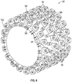
FIG. 6 is a perspective view of a hub; -
FIG. 7 is an end view of the hub illustrated inFIG. 6 ; -
FIG. 8 is a partial perspective view of a hub and securement pins; -
FIG. 9 is a partial end view of a hub with securement ligaments of the fan blades; -
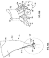
FIG. 10A is a perspective view of a blade; -
FIG. 10B is a partial view of a hub and a blade; -
FIG. 10C is a partial cross-sectional view of a blade; -
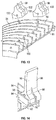
FIG. 11 is a side view illustrating a fan blade secured to a hub; -
FIG. 12 is a partial perspective cross-sectional view illustrating a fan blade secured to a hub; -
FIG. 13 is partial perspective cross-sectional view illustrating a hub; and -
FIG. 14 is a partial perspective cross-sectional view illustrating a hub. - A detailed description of one or more embodiments of the disclosed apparatus and method are presented herein by way of exemplification and not limitation with reference to the Figures.
-
FIG. 1 schematically illustrates agas turbine engine 20. Thegas turbine engine 20 is disclosed herein as a two-spool turbofan that generally incorporates a fan section 22, acompressor section 24, acombustor section 26 and aturbine section 28. Alternative engines might include an augmentor section (not shown) among other systems or features. The fan section 22 drives air along a bypass flow path B in a bypass duct, while thecompressor section 24 drives air along a core flow path C for compression and communication into thecombustor section 26 then expansion through theturbine section 28. Although depicted as a two-spool turbofan gas turbine engine in the disclosed non-limiting embodiment, it should be understood that the concepts described herein are not limited to use with two-spool turbofans as the teachings may be applied to other types of turbine engines including three-spool architectures. - The
exemplary engine 20 generally includes alow speed spool 30 and ahigh speed spool 32 mounted for rotation about an engine central longitudinal axis A relative to an enginestatic structure 36 viaseveral bearing systems 38. It should be understood that various bearingsystems 38 at various locations may alternatively or additionally be provided, and the location of bearingsystems 38 may be varied as appropriate to the application. - The
low speed spool 30 generally includes aninner shaft 40 that interconnects afan 42, alow pressure compressor 44 and alow pressure turbine 46. Theinner shaft 40 is connected to thefan 42 through a speed change mechanism, which in exemplarygas turbine engine 20 is illustrated as a gearedarchitecture 48 to drive thefan 42 at a lower speed than thelow speed spool 30. Thehigh speed spool 32 includes anouter shaft 50 that interconnects ahigh pressure compressor 52 andhigh pressure turbine 54. Acombustor 56 is arranged inexemplary gas turbine 20 between thehigh pressure compressor 52 and thehigh pressure turbine 54. An enginestatic structure 36 is arranged generally between thehigh pressure turbine 54 and thelow pressure turbine 46. The enginestatic structure 36 furthersupports bearing systems 38 in theturbine section 28. Theinner shaft 40 and theouter shaft 50 are concentric and rotate via bearingsystems 38 about the engine central longitudinal axis A which is collinear with their longitudinal axes. - The core airflow is compressed by the
low pressure compressor 44 then thehigh pressure compressor 52, mixed and burned with fuel in thecombustor 56, then expanded over thehigh pressure turbine 54 andlow pressure turbine 46. Theturbines low speed spool 30 andhigh speed spool 32 in response to the expansion. It will be appreciated that each of the positions of the fan section 22,compressor section 24,combustor section 26,turbine section 28, and fandrive gear system 48 may be varied. For example,gear system 48 may be located aft ofcombustor section 26 or even aft ofturbine section 28, and fan section 22 may be positioned forward or aft of the location ofgear system 48. - The
engine 20 in one example is a high-bypass geared aircraft engine. In a further example, theengine 20 bypass ratio is greater than about six (6), with an example embodiment being greater than about ten (10), the gearedarchitecture 48 is an epicyclic gear train, such as a planetary gear system or other gear system, with a gear reduction ratio of greater than about 2.3 and thelow pressure turbine 46 has a pressure ratio that is greater than about five. In one disclosed embodiment, theengine 20 bypass ratio is greater than about ten (10:1), the fan diameter is significantly larger than that of thelow pressure compressor 44, and thelow pressure turbine 46 has a pressure ratio that is greater than about five 5:1.Low pressure turbine 46 pressure ratio is pressure measured prior to inlet oflow pressure turbine 46 as related to the pressure at the outlet of thelow pressure turbine 46 prior to an exhaust nozzle. The gearedarchitecture 48 may be an epicycle gear train, such as a planetary gear system or other gear system, with a gear reduction ratio of greater than about 2.3:1. It should be understood, however, that the above parameters are only exemplary of one embodiment of a geared architecture engine and that the present disclosure is applicable to other gas turbine engines including direct drive turbofans. - A significant amount of thrust is provided by the bypass flow B due to the high bypass ratio. The fan section 22 of the
engine 20 is designed for a particular flight condition--typically cruise at about 0.8Mach and about 10,668 meters (35,000 feet). The flight condition of 0.8 Mach and 10,668 meters (35,000 ft), with the engine at its best fuel consumption--also known as "bucket cruise Thrust Specific Fuel Consumption ('TSFC')"--is the industry standard parameter of lbm of fuel being burned divided by lbf of thrust the engine produces at that minimum point. "Low fan pressure ratio" is the pressure ratio across the fan blade alone, without a Fan Exit Guide Vane ("FEGV") system. The low fan pressure ratio as disclosed herein according to one non-limiting embodiment is less than about 1.45. "Low corrected fan tip speed" is the actual fan tip speed in ft/sec divided by an industry standard temperature correction of [(Tram °R)/(518.7 °R)]0.5. The "Low corrected fan tip speed" as disclosed herein according to one non-limiting embodiment is less than about 350.5 m/sec (1150 ft/second). - Referring now to
FIGS. 2 and 3 , afan blade 70 of thefan 42 of theengine 20 is illustrated. As is known in the related arts, thefan 42 comprises a plurality offan blades 70. Thefan blade 70 also includes anairfoil 72 and a root orroot portion 74. The root orroot portion 74 is received within a slot orcavity 76 of a rotor, rotor disk, fan hub orhub 78 that rotates about axis A of theengine 20. Here root 74 is shown as a "dovetail" root. - Also illustrated in
FIG. 2 is a portion of astatic structure 80 theengine 20, afan shaft 82 androller bearings 84 located between thefan shaft 82 and thestatic structure 80. In one embodiment, theroller bearings 84 may be tapered roller bearings. Also illustrated inFIG. 2 is the bypass flow B and the core flow path C. Aportion 86 of thefan blade 70, that is located below the flow paths B and C and at or above the blade to root interface may have a larger overall thickness due to structural requirements. This larger or thicker portion may create a containment issue in the event of a failure of thefan blade 70 due to an undesired operational event. - For a blade containment test under 14 CFR 33.94, the
fan blade 70 is cut at the blade to dovetail interface represented by the dashedline 88. This releases atleast portion 86 of thefan blade 70 into the illustrated flow paths B and C. - Referring now to
FIGS. 4 and 5 , a hub orrotor 90 is illustrated. The hub or rotor is a coned hub or coned fan hub or coned rotor such that the hub or rotor angles upwardly in a radial direction with respect to axis A in a fore to aft direction as illustrated in the FIGS. The hub orrotor 90 has aleading edge 102 and a trailingedge 104. As used herein theleading edge 102 corresponds to the fore part of the hub and the trailing edge corresponds to the aft part of the hub. Thus and as the hub or rotor angles upwardly in a radial direction with respect to axis A in a fore to aft direction this may also be referred to as angling upwardly in a radial direction with respect to axis A from theleading edge 102 to the trailingedge 104. As used herein and as illustrated in the FIGS. a fore part of thehub 90 is closer to thefan 42 than an aft part of thehub 90 or in other words and as viewed in the attached FIGS. fore to aft is left to right when viewingFIG. 1 . - Here, a
line 91 which extends along a midline of the hub (coned) designates a mid-point between an inner and outer surface of the fan hub orrotor 90 or an average of the inner and outer surfaces. As illustrated for the coned hub, theline 91 has an angle ϕ with respect toline 92, which corresponds toline 88 inFIG. 4 (e.g., hub 78). In other arrangements, theline 92 is parallel to the axis A of theengine 20. As illustrated herein, the angle ϕ may vary as themidline 91 varies due to the curvature or undulation as well as the thickness of the hub orrotor 90. Thus and in an arrangement of a hub or rotor with asurface 93 that is parallel toaxis 92, theouter surface 93 may undulate with respect toaxis 92. In one embodiment, the thickness of the hub orrotor 90 may vary. As discussed above, themidline 91 of the hub orrotor 90 rotates about axis A of the engine. - In addition and as also illustrated, the cone angle ϕ of the hub or
rotor 90 allows reconfiguration of thestatic structure 80, theshaft 82 and thus the bearing 84 closest thehub 90 may be relocated to an area that results in improved rotor or hub dynamics. - In order to secure the
fan blade 70 to the hub orrotor 90, a plurality of attachment features 94 extend fromsurface 93 and the fan blade is secured thereto by a plurality of ligaments or connectingmembers 96 which are secured to thefan blade 70 at one end and extend to the attachment features 94 at the other end. - The ligaments or connecting
members 96 may be secured to the attachment features 94 by a pin or pins 98.Pins 98 may be press fit into its corresponding opening in order to secure the ligaments or connectingmembers 96 to thehub 90. Of course, alternative methods of securement are considered to be within the scope of the present disclosure. Still further and as illustrated in at leastFIGS. 6-9 , the rotor orhub 90 and itssurface 93, may have a plurality of attachment features 94 of varying sizes (e.g., height, width, length, etc.) and orientations. Each of the features have anopening 100 configured to receive a portion of apin 98. In addition and similar to the attachment features 94, the pins may also have varying sizes. Still further, some of the attachment features 94 are located on aforward end 102 of the hub 90.Some of the attachment features 94 may be located on anaft end 104 of thehub 90. The attachment features 94 may be located on both the forward end or leadingedge 102 and theaft end 104 of thehub 90. - The attachment features 94 may be integrally formed with the
hub 90 or separately secured thereto. - By providing a hub with a plurality of attachment features or
support brackets 94 and securing the blade thereto with a plurality of ligaments or connectingmembers 96 and associatedpins 98, the blade root and corresponding slots in the rotor can be removed. As such, this allows thecut line 88 for use in a blade containment test under 14 CFR 33.94, to be moved andportion 86 of thefan blade 70 is significantly smaller. By makingportion 86 smaller, rotating imbalances are improved and the impact energy of a released blade into the fan containment case (FCC) is reduced. - Still further and by providing an undulating
surface 93 as illustrated in at leastFIG. 5 , the stiffness/strength of each fan blade ligament attachment can be designed independently as well as allowing for the implementation of more than one Gaussian curvature in the design (e.g., conical hubs). By designing at least some of the attachment features 94 independently the design is free from the constraints of a dove tail root configuration. In the dove tail root configuration, the design must have only one Gaussian curvature. In other words, if the design employs more than one Gaussian curvature the root will not be able to slide into the dovetail. - By varying the Gaussian curvature of the hub, the related blade design may also vary. As such, the hub and the blade securement thereto below the core flow path C can vary. This allows the blade attachment to be configured in order to account for centripetal forces or stresses encountered by the blade and/or areas of its securement to the hub.
- Referring now to at least
FIGS. 10A ,10C ,11 and 12 , thefan blade 70 has aleading edge 106, a trailingedge 108, atip portion 110 and a bottom orattachment portion 112. Aprotective sheath 114 may be secured to theleading edge 106 of thefan blade 70. - In order to reduce weight, the fan blades may be made out of aluminum, and to protect the leading edge from erosion, the
protective sheath 114 may be formed from titanium. Although aluminum and titanium are disclosed other equivalent materials are contemplated to be within the scope of the present disclosure. - As illustrated in at least
FIGS. 11 and 12 , theprotective sheath 114 extends along the entireleading edge 106 from thetip portion 110 past the bottom orattachment portion 112 and is then secured to the attachment features 94 located at theleading edge 102 of thehub 90. As illustrated inFIG. 12 , theprotective sheath 114 may have anopening 116 that is aligned withopenings 100 of the attachment features 94 located on either side of theprotective sheath 114 at theleading edge 102 of thehub 90. Accordingly, pin 98 can be inserted intoopenings protective sheath 114 to the leading edge of thehub 90. - An attachment member or
ligament member 96 may be located at the leading edge of the blade and this member is secured to theleading edge 102 of the hub. Here, this attachment member orligament member 96 may be integrally formed with theblade 70. See for example,FIG. 5 . - The trailing
edge 108 may also have aprotective sheath 118 secured thereto. Similar to the leading edge, theprotective sheath 118 of the trailing edge may extend from thetip 110 of theblade 70 past theattachment portion 112 and is secured to the attachment features 94 located on theaft end 104 of thehub 90. - An attachment member or
ligament member 96 may be located at the trailing edge of the blade and this member is secured to the trailingedge 104 of the hub. Here, this attachment member orligament member 96 may be integrally formed with theblade 70. - The
blade 70 may haveprotective sheaths leading edge 106 and the trailingedge 108. Alternatively, theblade 70 may only have aprotective sheath 114 located at theleading edge 106 or only have aprotective sheath 118 located at the trailingedge 108 of theblade 70. - The
hub 90 andblades 70 are configured such that dovetail mounted roots and corresponding slots are no longer used to secure the blades to the hub. By removing the root portion and corresponding slot, the need for a blade setback proximate to the leading edge of theairfoil 72 at its point of securement to thehub 90 is no longer necessary. In dovetail root designs, a blade setback is sometimes employed in the area depicted by the dashedlines 120 in at leastFIGS. 10A and12 . Typically these setbacks are used to reduce stress gradients in the thin leading edge in order to withstand potential bird strikes and foreign object damage (FOD). As such and through the designs disclosed herein, the centrifugal loads and stresses acting on the leading and trailing edges of the fan blade can be reacted to through the use of the attachment of the blade and/or the protective sheath at the leading and trailing edges of the hub or rotor. - Referring now to
FIGS. 13 and 14 , the attachment features 94 of the rotor orhub 90 may be continuous walls or attachment features that extend continuously about the periphery of thehub 90. The attachment features orwalls 94 may be spaced from each other in an axial direction as represented by axis A. In addition, thecontinuous walls 94 may have varying heights extending in a radial direction away from axis A and away from thesurface 93. As mentioned above, thesurface 93 may also undulate and/orhub 90 may be conical in shape in a fore to aft direction. - The walls or attachment features 94 may be formed in the
hub 90 via a lathing process. As such, the hub may be placed on a turning machine or lathe and a cutting tool is used to remove surface material in order to form the walls or attachment features 94. - As mentioned above, the walls or attachment features 94 may extend continuously about the
hub 90. The walls or attachment features may extend partially about hub 90 (e.g., not completely around) or some of the walls or attachment features 94 may extend completely around and some may not. - As illustrated, the ligaments or connecting
members 96 have anopening 130 for receipt of pin ormember 98 therein. In addition, the ligaments or connectingmembers 96 may also have a slot or opening 132 in order to receive a portion ofwall 94 therein. Accordingly and as the ligaments or connectingmembers 96 are placed on a portion of wall 94 a portion of the wall or feature 94 is received in slot oropening 132. Once opening 130 is aligned with opening 100 a pin ormember 98 is inserted therein in order to secure the ligaments or connectingmembers 96 to thehub 90. The ligaments or connectingmembers 96 may have a portion on either side of wall orfeature 94. - As illustrated in at least
FIG. 14 , the ligaments or connectingmembers 96 may be located on opposite sides of wall orfeature 94. A pair of ligaments or connectingmembers 96 may be secured to opposite sides of wall or feature 94 viapin 98. - The term "about" is intended to include the degree of error associated with measurement of the particular quantity based upon the equipment available at the time of filing the application.
- The terminology used herein is for the purpose of describing particular embodiments only and is not intended to be limiting of the present disclosure. As used herein, the singular forms "a", "an" and "the" are intended to include the plural forms as well, unless the context clearly indicates otherwise. It will be further understood that the terms "comprises" and/or "comprising," when used in this specification, specify the presence of stated features, integers, steps, operations, elements, and/or components, but do not preclude the presence or addition of one or more other features, integers, steps, operations, element components, and/or groups thereof.
- While the present disclosure has been described with reference to an exemplary embodiment or embodiments, it will be understood by those skilled in the art that various changes may be made and equivalents may be substituted for elements thereof without departing from the scope of the present disclosure. Therefore, it is intended that the present disclosure not be limited to the particular embodiment disclosed as the best mode contemplated for carrying out this present disclosure, but that the present disclosure will include all embodiments falling within the scope of the claims.
Claims (10)
- A gas turbine engine (20), comprising:a conically shaped fan hub (90), the outer surface (93) of the hub having at least two different Gaussian curvatures;a plurality of attachment features (94) located on the outer surface (93) of the hub (90), wherein at least some of the plurality of attachment features (94) extend radially away from the outer surface (93) and are axially aligned with each other and at least some of the plurality of attachment features (94) extending radially away from the outer surface (93) and are off set from each other;a plurality of fan blades (70) each having a plurality of connecting members (96) secured to the fan hub (90) via the plurality of attachment features (94), each of the plurality of attachment features (94) have an opening (100) configured to receive a portion of a pin (98) for securing the plurality of blades (70) to the fan hub; andwherein at least some of the plurality of attachment features (94) are located on a forward leading edge (102) of the hub (90) and extend axially away from the leading edge.
- The gas turbine engine (20) as in claim 1, wherein at least some of the plurality of attachment features (94) are located on a trailing edge (104) of the hub (90).
- The gas turbine engine (20) as in claim 2, wherein the least some of the plurality of attachment features (94) located on the trailing edge (104) of the hub (90) extend axially from the trailing edge (104) of the hub (90).
- The gas turbine engine (20) as in any preceding claim, wherein the plurality of attachment features (94) located on the outer surface (93) of the hub (90) are a plurality of walls axially spaced from each other that extend continuously about the outer surface (93) of the hub (90)
- The gas turbine engine (20) as in any preceding claim, wherein the outer surface (93) of the hub (90) undulates.
- The gas turbine engine (20) as in any preceding claim, wherein the plurality of connecting members (96) extend from a bottom portion of each of the plurality of fan blades.
- The gas turbine engine (20) as in any of claims 1 to 5, wherein at least one of the plurality of connecting members (96) is secured to at least one of the plurality of attachment features (94) located on the leading edge (102) of the hub (90).
- The gas turbine engine (20) as in any of claims 1 to 5, wherein at least some of the plurality of fan blades (70) have a protective member (114) secured to a leading edge (106) of the at least some of the plurality of fan blades (70) wherein the protective member (114) is secured to at least one of the plurality of attachment features (94) located on the leading edge (102) of the hub (90).
- The gas turbine engine (20) of any of claims 1 to 5 and 8, wherein at least some of the plurality of fan blades (70) have a protective member (118) secured to a trailing edge (108) of the at least some of the plurality of fan blades (70) and wherein the protective member (118) is secured to at least one of the plurality of attachment features (94) located on the trailing edge (104) of the hub (90).
- A method of securing a fan blade (70) to a conically shaped fan hub (90) of a gas turbine engine (20), comprising:inserting a plurality of pins (98) through a plurality of attachment features (94) located on an outer surface (93) of the hub (90) and at least some of the plurality of attachment features (94) located on a forward leading edge (102) of the hub (90), wherein the plurality of pins (98) secure a plurality of connecting members (96) of the plurality of blades (70) to the hub (90), wherein at least some of the plurality of the connecting members (96) extend from a leading edge (106) of each of the plurality of fan blades (70) to a corresponding attachment feature (94) located on the leading edge (102) of the hub (90), wherein the outer surface of the conically shaped fan hub (90) has at least two different Gaussian curvatures.
Applications Claiming Priority (1)
| Application Number | Priority Date | Filing Date | Title |
|---|---|---|---|
| US15/689,953 US10280767B2 (en) | 2017-08-29 | 2017-08-29 | Fan hub attachment for leading and trailing edges of fan blades |
Publications (2)
| Publication Number | Publication Date |
|---|---|
| EP3450689A1 EP3450689A1 (en) | 2019-03-06 |
| EP3450689B1 true EP3450689B1 (en) | 2021-10-06 |
Family
ID=63449301
Family Applications (1)
| Application Number | Title | Priority Date | Filing Date |
|---|---|---|---|
| EP18191573.7A Active EP3450689B1 (en) | 2017-08-29 | 2018-08-29 | Gas turbine engine having a fan hub attachment and securing method therefor |
Country Status (2)
| Country | Link |
|---|---|
| US (1) | US10280767B2 (en) |
| EP (1) | EP3450689B1 (en) |
Families Citing this family (1)
| Publication number | Priority date | Publication date | Assignee | Title |
|---|---|---|---|---|
| FR3106363B1 (en) | 2020-01-22 | 2022-09-09 | Safran Aircraft Engines | FAN MODULE FOR AN AIRCRAFT TURBOMACHINE TEST BENCH |
Citations (3)
| Publication number | Priority date | Publication date | Assignee | Title |
|---|---|---|---|---|
| US3694104A (en) * | 1970-10-07 | 1972-09-26 | Garrett Corp | Turbomachinery blade |
| US6155788A (en) * | 1998-07-07 | 2000-12-05 | Rolls-Royce Plc | Rotor assembly |
| EP2570598A2 (en) * | 2011-05-26 | 2013-03-20 | United Technologies Corporation | Rotor disk assembly for a gas turbine engine |
Family Cites Families (10)
| Publication number | Priority date | Publication date | Assignee | Title |
|---|---|---|---|---|
| DE1531374A1 (en) | 1967-09-12 | 1970-01-29 | Messerschmitt Boelkow Blohm | Rotor blade made of fiber-reinforced plastic with a loop-like blade root |
| US5240377A (en) | 1992-02-25 | 1993-08-31 | Williams International Corporation | Composite fan blade |
| GB2268978B (en) * | 1992-07-21 | 1995-11-08 | Rolls Royce Plc | Fan for a ducted fan gas turbine engine |
| US7399159B2 (en) | 2003-06-25 | 2008-07-15 | Florida Turbine Technologies, Inc | Detachable leading edge for airfoils |
| FR2913734B1 (en) | 2007-03-16 | 2009-05-01 | Snecma Sa | TURBOMACHINE BLOWER |
| FR2971822B1 (en) | 2011-02-21 | 2015-04-24 | Snecma | BLOWER ROTOR, ESPECIALLY FOR A TURBOMACHINE |
| DE102012015136A1 (en) | 2012-07-30 | 2014-01-30 | Rolls-Royce Deutschland Ltd & Co Kg | Decoupled compressor blade of a gas turbine |
| US10119423B2 (en) | 2012-09-20 | 2018-11-06 | United Technologies Corporation | Gas turbine engine fan spacer platform attachments |
| FR3014151B1 (en) | 2013-11-29 | 2015-12-04 | Snecma | BLOWER, ESPECIALLY FOR A TURBOMACHINE |
| US10371162B2 (en) * | 2016-10-05 | 2019-08-06 | Pratt & Whitney Canada Corp. | Integrally bladed fan rotor |
-
2017
- 2017-08-29 US US15/689,953 patent/US10280767B2/en active Active
-
2018
- 2018-08-29 EP EP18191573.7A patent/EP3450689B1/en active Active
Patent Citations (3)
| Publication number | Priority date | Publication date | Assignee | Title |
|---|---|---|---|---|
| US3694104A (en) * | 1970-10-07 | 1972-09-26 | Garrett Corp | Turbomachinery blade |
| US6155788A (en) * | 1998-07-07 | 2000-12-05 | Rolls-Royce Plc | Rotor assembly |
| EP2570598A2 (en) * | 2011-05-26 | 2013-03-20 | United Technologies Corporation | Rotor disk assembly for a gas turbine engine |
Also Published As
| Publication number | Publication date |
|---|---|
| US20190063236A1 (en) | 2019-02-28 |
| EP3450689A1 (en) | 2019-03-06 |
| US10280767B2 (en) | 2019-05-07 |
Similar Documents
| Publication | Publication Date | Title |
|---|---|---|
| EP2964934B1 (en) | Gas turbine engine component having variable width feather seal slot | |
| EP2981676B1 (en) | Engine component having support with intermediate layer | |
| EP3054088B1 (en) | Gas turbine engine rotor disk balancing | |
| EP2952683B1 (en) | Gas turbine engine airfoil with large thickness properties | |
| EP3584406B1 (en) | Clip and pin balance for rotor | |
| EP3461993B1 (en) | Gas turbine engine blade | |
| EP3467260B1 (en) | Turbine blade with bowed tip | |
| US10280767B2 (en) | Fan hub attachment for leading and trailing edges of fan blades | |
| EP3611338B1 (en) | Dovetail weight system for rotor balance | |
| EP3097289B1 (en) | Turbine engine balancing structure and method | |
| EP3597872B1 (en) | Fan case assembly for a gas turbine engine | |
| EP3450688B1 (en) | Gas turbine engine and method for reducing blade off loads | |
| EP2993300B1 (en) | Gas turbine engine airfoil structure | |
| EP3483393B1 (en) | Fan assembly of a gas turbine engine with a tip shroud | |
| EP2890878B1 (en) | Blade outer air seal | |
| EP3470627B1 (en) | Gas turbine engine airfoil | |
| EP3228856B1 (en) | Fan blade removal feature for a gas turbine engine and associated method | |
| EP3789586B1 (en) | Aerodynamic element assembly for a gas turbine engine | |
| EP3550105B1 (en) | Gas turbine engine rotor disk | |
| EP3159492B1 (en) | Cooling passages for gas turbine engine component | |
| EP3045658B1 (en) | Gas turbine engine rotor | |
| EP3508694B1 (en) | Gas turbine engine airfoil with cooling path |
Legal Events
| Date | Code | Title | Description |
|---|---|---|---|
| PUAI | Public reference made under article 153(3) epc to a published international application that has entered the european phase |
Free format text: ORIGINAL CODE: 0009012 |
|
| STAA | Information on the status of an ep patent application or granted ep patent |
Free format text: STATUS: THE APPLICATION HAS BEEN PUBLISHED |
|
| AK | Designated contracting states |
Kind code of ref document: A1 Designated state(s): AL AT BE BG CH CY CZ DE DK EE ES FI FR GB GR HR HU IE IS IT LI LT LU LV MC MK MT NL NO PL PT RO RS SE SI SK SM TR |
|
| AX | Request for extension of the european patent |
Extension state: BA ME |
|
| STAA | Information on the status of an ep patent application or granted ep patent |
Free format text: STATUS: REQUEST FOR EXAMINATION WAS MADE |
|
| 17P | Request for examination filed |
Effective date: 20190906 |
|
| RBV | Designated contracting states (corrected) |
Designated state(s): AL AT BE BG CH CY CZ DE DK EE ES FI FR GB GR HR HU IE IS IT LI LT LU LV MC MK MT NL NO PL PT RO RS SE SI SK SM TR |
|
| STAA | Information on the status of an ep patent application or granted ep patent |
Free format text: STATUS: EXAMINATION IS IN PROGRESS |
|
| 17Q | First examination report despatched |
Effective date: 20200319 |
|
| RAP1 | Party data changed (applicant data changed or rights of an application transferred) |
Owner name: RAYTHEON TECHNOLOGIES CORPORATION |
|
| GRAP | Despatch of communication of intention to grant a patent |
Free format text: ORIGINAL CODE: EPIDOSNIGR1 |
|
| STAA | Information on the status of an ep patent application or granted ep patent |
Free format text: STATUS: GRANT OF PATENT IS INTENDED |
|
| INTG | Intention to grant announced |
Effective date: 20210422 |
|
| GRAS | Grant fee paid |
Free format text: ORIGINAL CODE: EPIDOSNIGR3 |
|
| GRAA | (expected) grant |
Free format text: ORIGINAL CODE: 0009210 |
|
| STAA | Information on the status of an ep patent application or granted ep patent |
Free format text: STATUS: THE PATENT HAS BEEN GRANTED |
|
| AK | Designated contracting states |
Kind code of ref document: B1 Designated state(s): AL AT BE BG CH CY CZ DE DK EE ES FI FR GB GR HR HU IE IS IT LI LT LU LV MC MK MT NL NO PL PT RO RS SE SI SK SM TR |
|
| REG | Reference to a national code |
Ref country code: GB Ref legal event code: FG4D |
|
| REG | Reference to a national code |
Ref country code: CH Ref legal event code: EP Ref country code: AT Ref legal event code: REF Ref document number: 1436405 Country of ref document: AT Kind code of ref document: T Effective date: 20211015 |
|
| REG | Reference to a national code |
Ref country code: DE Ref legal event code: R096 Ref document number: 602018024546 Country of ref document: DE |
|
| REG | Reference to a national code |
Ref country code: IE Ref legal event code: FG4D |
|
| REG | Reference to a national code |
Ref country code: LT Ref legal event code: MG9D |
|
| REG | Reference to a national code |
Ref country code: NL Ref legal event code: MP Effective date: 20211006 |
|
| REG | Reference to a national code |
Ref country code: AT Ref legal event code: MK05 Ref document number: 1436405 Country of ref document: AT Kind code of ref document: T Effective date: 20211006 |
|
| PG25 | Lapsed in a contracting state [announced via postgrant information from national office to epo] |
Ref country code: RS Free format text: LAPSE BECAUSE OF FAILURE TO SUBMIT A TRANSLATION OF THE DESCRIPTION OR TO PAY THE FEE WITHIN THE PRESCRIBED TIME-LIMIT Effective date: 20211006 Ref country code: LT Free format text: LAPSE BECAUSE OF FAILURE TO SUBMIT A TRANSLATION OF THE DESCRIPTION OR TO PAY THE FEE WITHIN THE PRESCRIBED TIME-LIMIT Effective date: 20211006 Ref country code: FI Free format text: LAPSE BECAUSE OF FAILURE TO SUBMIT A TRANSLATION OF THE DESCRIPTION OR TO PAY THE FEE WITHIN THE PRESCRIBED TIME-LIMIT Effective date: 20211006 Ref country code: BG Free format text: LAPSE BECAUSE OF FAILURE TO SUBMIT A TRANSLATION OF THE DESCRIPTION OR TO PAY THE FEE WITHIN THE PRESCRIBED TIME-LIMIT Effective date: 20220106 Ref country code: AT Free format text: LAPSE BECAUSE OF FAILURE TO SUBMIT A TRANSLATION OF THE DESCRIPTION OR TO PAY THE FEE WITHIN THE PRESCRIBED TIME-LIMIT Effective date: 20211006 |
|
| PG25 | Lapsed in a contracting state [announced via postgrant information from national office to epo] |
Ref country code: IS Free format text: LAPSE BECAUSE OF FAILURE TO SUBMIT A TRANSLATION OF THE DESCRIPTION OR TO PAY THE FEE WITHIN THE PRESCRIBED TIME-LIMIT Effective date: 20220206 Ref country code: SE Free format text: LAPSE BECAUSE OF FAILURE TO SUBMIT A TRANSLATION OF THE DESCRIPTION OR TO PAY THE FEE WITHIN THE PRESCRIBED TIME-LIMIT Effective date: 20211006 Ref country code: PT Free format text: LAPSE BECAUSE OF FAILURE TO SUBMIT A TRANSLATION OF THE DESCRIPTION OR TO PAY THE FEE WITHIN THE PRESCRIBED TIME-LIMIT Effective date: 20220207 Ref country code: PL Free format text: LAPSE BECAUSE OF FAILURE TO SUBMIT A TRANSLATION OF THE DESCRIPTION OR TO PAY THE FEE WITHIN THE PRESCRIBED TIME-LIMIT Effective date: 20211006 Ref country code: NO Free format text: LAPSE BECAUSE OF FAILURE TO SUBMIT A TRANSLATION OF THE DESCRIPTION OR TO PAY THE FEE WITHIN THE PRESCRIBED TIME-LIMIT Effective date: 20220106 Ref country code: NL Free format text: LAPSE BECAUSE OF FAILURE TO SUBMIT A TRANSLATION OF THE DESCRIPTION OR TO PAY THE FEE WITHIN THE PRESCRIBED TIME-LIMIT Effective date: 20211006 Ref country code: LV Free format text: LAPSE BECAUSE OF FAILURE TO SUBMIT A TRANSLATION OF THE DESCRIPTION OR TO PAY THE FEE WITHIN THE PRESCRIBED TIME-LIMIT Effective date: 20211006 Ref country code: HR Free format text: LAPSE BECAUSE OF FAILURE TO SUBMIT A TRANSLATION OF THE DESCRIPTION OR TO PAY THE FEE WITHIN THE PRESCRIBED TIME-LIMIT Effective date: 20211006 Ref country code: GR Free format text: LAPSE BECAUSE OF FAILURE TO SUBMIT A TRANSLATION OF THE DESCRIPTION OR TO PAY THE FEE WITHIN THE PRESCRIBED TIME-LIMIT Effective date: 20220107 Ref country code: ES Free format text: LAPSE BECAUSE OF FAILURE TO SUBMIT A TRANSLATION OF THE DESCRIPTION OR TO PAY THE FEE WITHIN THE PRESCRIBED TIME-LIMIT Effective date: 20211006 |
|
| REG | Reference to a national code |
Ref country code: DE Ref legal event code: R097 Ref document number: 602018024546 Country of ref document: DE |
|
| PG25 | Lapsed in a contracting state [announced via postgrant information from national office to epo] |
Ref country code: SM Free format text: LAPSE BECAUSE OF FAILURE TO SUBMIT A TRANSLATION OF THE DESCRIPTION OR TO PAY THE FEE WITHIN THE PRESCRIBED TIME-LIMIT Effective date: 20211006 Ref country code: SK Free format text: LAPSE BECAUSE OF FAILURE TO SUBMIT A TRANSLATION OF THE DESCRIPTION OR TO PAY THE FEE WITHIN THE PRESCRIBED TIME-LIMIT Effective date: 20211006 Ref country code: RO Free format text: LAPSE BECAUSE OF FAILURE TO SUBMIT A TRANSLATION OF THE DESCRIPTION OR TO PAY THE FEE WITHIN THE PRESCRIBED TIME-LIMIT Effective date: 20211006 Ref country code: EE Free format text: LAPSE BECAUSE OF FAILURE TO SUBMIT A TRANSLATION OF THE DESCRIPTION OR TO PAY THE FEE WITHIN THE PRESCRIBED TIME-LIMIT Effective date: 20211006 Ref country code: DK Free format text: LAPSE BECAUSE OF FAILURE TO SUBMIT A TRANSLATION OF THE DESCRIPTION OR TO PAY THE FEE WITHIN THE PRESCRIBED TIME-LIMIT Effective date: 20211006 Ref country code: CZ Free format text: LAPSE BECAUSE OF FAILURE TO SUBMIT A TRANSLATION OF THE DESCRIPTION OR TO PAY THE FEE WITHIN THE PRESCRIBED TIME-LIMIT Effective date: 20211006 |
|
| PLBE | No opposition filed within time limit |
Free format text: ORIGINAL CODE: 0009261 |
|
| STAA | Information on the status of an ep patent application or granted ep patent |
Free format text: STATUS: NO OPPOSITION FILED WITHIN TIME LIMIT |
|
| 26N | No opposition filed |
Effective date: 20220707 |
|
| PG25 | Lapsed in a contracting state [announced via postgrant information from national office to epo] |
Ref country code: AL Free format text: LAPSE BECAUSE OF FAILURE TO SUBMIT A TRANSLATION OF THE DESCRIPTION OR TO PAY THE FEE WITHIN THE PRESCRIBED TIME-LIMIT Effective date: 20211006 |
|
| PG25 | Lapsed in a contracting state [announced via postgrant information from national office to epo] |
Ref country code: SI Free format text: LAPSE BECAUSE OF FAILURE TO SUBMIT A TRANSLATION OF THE DESCRIPTION OR TO PAY THE FEE WITHIN THE PRESCRIBED TIME-LIMIT Effective date: 20211006 |
|
| PG25 | Lapsed in a contracting state [announced via postgrant information from national office to epo] |
Ref country code: MC Free format text: LAPSE BECAUSE OF FAILURE TO SUBMIT A TRANSLATION OF THE DESCRIPTION OR TO PAY THE FEE WITHIN THE PRESCRIBED TIME-LIMIT Effective date: 20211006 |
|
| REG | Reference to a national code |
Ref country code: CH Ref legal event code: PL |
|
| PG25 | Lapsed in a contracting state [announced via postgrant information from national office to epo] |
Ref country code: LU Free format text: LAPSE BECAUSE OF NON-PAYMENT OF DUE FEES Effective date: 20220829 Ref country code: LI Free format text: LAPSE BECAUSE OF NON-PAYMENT OF DUE FEES Effective date: 20220831 Ref country code: CH Free format text: LAPSE BECAUSE OF NON-PAYMENT OF DUE FEES Effective date: 20220831 |
|
| REG | Reference to a national code |
Ref country code: BE Ref legal event code: MM Effective date: 20220831 |
|
| PG25 | Lapsed in a contracting state [announced via postgrant information from national office to epo] |
Ref country code: IT Free format text: LAPSE BECAUSE OF FAILURE TO SUBMIT A TRANSLATION OF THE DESCRIPTION OR TO PAY THE FEE WITHIN THE PRESCRIBED TIME-LIMIT Effective date: 20211006 |
|
| P01 | Opt-out of the competence of the unified patent court (upc) registered |
Effective date: 20230521 |
|
| PG25 | Lapsed in a contracting state [announced via postgrant information from national office to epo] |
Ref country code: IE Free format text: LAPSE BECAUSE OF NON-PAYMENT OF DUE FEES Effective date: 20220829 |
|
| PG25 | Lapsed in a contracting state [announced via postgrant information from national office to epo] |
Ref country code: BE Free format text: LAPSE BECAUSE OF NON-PAYMENT OF DUE FEES Effective date: 20220831 |
|
| PG25 | Lapsed in a contracting state [announced via postgrant information from national office to epo] |
Ref country code: HU Free format text: LAPSE BECAUSE OF FAILURE TO SUBMIT A TRANSLATION OF THE DESCRIPTION OR TO PAY THE FEE WITHIN THE PRESCRIBED TIME-LIMIT; INVALID AB INITIO Effective date: 20180829 |
|
| PG25 | Lapsed in a contracting state [announced via postgrant information from national office to epo] |
Ref country code: CY Free format text: LAPSE BECAUSE OF FAILURE TO SUBMIT A TRANSLATION OF THE DESCRIPTION OR TO PAY THE FEE WITHIN THE PRESCRIBED TIME-LIMIT Effective date: 20211006 |
|
| PG25 | Lapsed in a contracting state [announced via postgrant information from national office to epo] |
Ref country code: MK Free format text: LAPSE BECAUSE OF FAILURE TO SUBMIT A TRANSLATION OF THE DESCRIPTION OR TO PAY THE FEE WITHIN THE PRESCRIBED TIME-LIMIT Effective date: 20211006 |
|
| PG25 | Lapsed in a contracting state [announced via postgrant information from national office to epo] |
Ref country code: MT Free format text: LAPSE BECAUSE OF FAILURE TO SUBMIT A TRANSLATION OF THE DESCRIPTION OR TO PAY THE FEE WITHIN THE PRESCRIBED TIME-LIMIT Effective date: 20211006 |
|
| REG | Reference to a national code |
Ref country code: DE Ref legal event code: R081 Ref document number: 602018024546 Country of ref document: DE Owner name: RTX CORPORATION (N.D.GES.D. STAATES DELAWARE),, US Free format text: FORMER OWNER: RAYTHEON TECHNOLOGIES CORPORATION, FARMINGTON, CT, US |
|
| PGFP | Annual fee paid to national office [announced via postgrant information from national office to epo] |
Ref country code: DE Payment date: 20250724 Year of fee payment: 8 |
|
| PGFP | Annual fee paid to national office [announced via postgrant information from national office to epo] |
Ref country code: GB Payment date: 20250725 Year of fee payment: 8 |
|
| PGFP | Annual fee paid to national office [announced via postgrant information from national office to epo] |
Ref country code: FR Payment date: 20250723 Year of fee payment: 8 |
|
| PG25 | Lapsed in a contracting state [announced via postgrant information from national office to epo] |
Ref country code: TR Free format text: LAPSE BECAUSE OF FAILURE TO SUBMIT A TRANSLATION OF THE DESCRIPTION OR TO PAY THE FEE WITHIN THE PRESCRIBED TIME-LIMIT Effective date: 20211006 |