EP3450666B1 - Slide hinge and cabinet - Google Patents
Slide hinge and cabinet Download PDFInfo
- Publication number
- EP3450666B1 EP3450666B1 EP18189307.4A EP18189307A EP3450666B1 EP 3450666 B1 EP3450666 B1 EP 3450666B1 EP 18189307 A EP18189307 A EP 18189307A EP 3450666 B1 EP3450666 B1 EP 3450666B1
- Authority
- EP
- European Patent Office
- Prior art keywords
- portions
- case
- coupling
- attaching
- locking
- Prior art date
- Legal status (The legal status is an assumption and is not a legal conclusion. Google has not performed a legal analysis and makes no representation as to the accuracy of the status listed.)
- Active
Links
- 230000008878 coupling Effects 0.000 claims description 106
- 238000010168 coupling process Methods 0.000 claims description 106
- 238000005859 coupling reaction Methods 0.000 claims description 106
- 210000000078 claw Anatomy 0.000 claims description 18
- 230000003014 reinforcing effect Effects 0.000 claims description 15
- 238000003780 insertion Methods 0.000 claims description 13
- 230000037431 insertion Effects 0.000 claims description 13
- 229920003002 synthetic resin Polymers 0.000 claims description 12
- 239000000057 synthetic resin Substances 0.000 claims description 12
- POIUWJQBRNEFGX-XAMSXPGMSA-N cathelicidin Chemical compound C([C@@H](C(=O)N[C@@H](CCCNC(N)=N)C(=O)N[C@@H](CCCCN)C(=O)N[C@@H](CO)C(=O)N[C@@H](CCCCN)C(=O)N[C@@H](CCC(O)=O)C(=O)N[C@@H](CCCCN)C(=O)N[C@@H]([C@@H](C)CC)C(=O)NCC(=O)N[C@@H](CCCCN)C(=O)N[C@@H](CCC(O)=O)C(=O)N[C@@H](CC=1C=CC=CC=1)C(=O)N[C@@H](CCCCN)C(=O)N[C@@H](CCCNC(N)=N)C(=O)N[C@@H]([C@@H](C)CC)C(=O)N[C@@H](C(C)C)C(=O)N[C@@H](CCC(N)=O)C(=O)N[C@@H](CCCNC(N)=N)C(=O)N[C@@H]([C@@H](C)CC)C(=O)N[C@@H](CCCCN)C(=O)N[C@@H](CC(O)=O)C(=O)N[C@@H](CC=1C=CC=CC=1)C(=O)N[C@@H](CC(C)C)C(=O)N[C@@H](CCCNC(N)=N)C(=O)N[C@@H](CC(N)=O)C(=O)N[C@@H](CC(C)C)C(=O)N[C@@H](C(C)C)C(=O)N1[C@@H](CCC1)C(=O)N[C@@H](CCCNC(N)=N)C(=O)N[C@@H]([C@@H](C)O)C(=O)N[C@@H](CCC(O)=O)C(=O)N[C@@H](CO)C(O)=O)NC(=O)[C@H](CC=1C=CC=CC=1)NC(=O)[C@H](CC(O)=O)NC(=O)CNC(=O)[C@H](CC(C)C)NC(=O)[C@@H](N)CC(C)C)C1=CC=CC=C1 POIUWJQBRNEFGX-XAMSXPGMSA-N 0.000 description 11
- 230000000694 effects Effects 0.000 description 5
- 239000000463 material Substances 0.000 description 4
- 238000005192 partition Methods 0.000 description 3
- 238000004891 communication Methods 0.000 description 2
- 238000000034 method Methods 0.000 description 2
- 230000001419 dependent effect Effects 0.000 description 1
- 239000002184 metal Substances 0.000 description 1
- 230000002093 peripheral effect Effects 0.000 description 1
- 239000011120 plywood Substances 0.000 description 1
- 229920005989 resin Polymers 0.000 description 1
- 239000011347 resin Substances 0.000 description 1
- 239000011343 solid material Substances 0.000 description 1
- 229910001220 stainless steel Inorganic materials 0.000 description 1
- 239000010935 stainless steel Substances 0.000 description 1
Images


Classifications
-
- E—FIXED CONSTRUCTIONS
- E05—LOCKS; KEYS; WINDOW OR DOOR FITTINGS; SAFES
- E05D—HINGES OR SUSPENSION DEVICES FOR DOORS, WINDOWS OR WINGS
- E05D5/00—Construction of single parts, e.g. the parts for attachment
- E05D5/02—Parts for attachment, e.g. flaps
- E05D5/0276—Parts for attachment, e.g. flaps for attachment to cabinets or furniture, the hinge having two or more pins
-
- E—FIXED CONSTRUCTIONS
- E05—LOCKS; KEYS; WINDOW OR DOOR FITTINGS; SAFES
- E05D—HINGES OR SUSPENSION DEVICES FOR DOORS, WINDOWS OR WINGS
- E05D3/00—Hinges with pins
- E05D3/06—Hinges with pins with two or more pins
- E05D3/14—Hinges with pins with two or more pins with four parallel pins and two arms
- E05D3/142—Hinges with pins with two or more pins with four parallel pins and two arms with at least one of the hinge parts having a cup-shaped fixing part, e.g. for attachment to cabinets or furniture
-
- E—FIXED CONSTRUCTIONS
- E05—LOCKS; KEYS; WINDOW OR DOOR FITTINGS; SAFES
- E05D—HINGES OR SUSPENSION DEVICES FOR DOORS, WINDOWS OR WINGS
- E05D9/00—Flaps or sleeves specially designed for making from particular material, e.g. hoop-iron, sheet metal, plastics
- E05D9/005—Flaps or sleeves specially designed for making from particular material, e.g. hoop-iron, sheet metal, plastics from plastics
-
- E—FIXED CONSTRUCTIONS
- E05—LOCKS; KEYS; WINDOW OR DOOR FITTINGS; SAFES
- E05Y—INDEXING SCHEME RELATING TO HINGES OR OTHER SUSPENSION DEVICES FOR DOORS, WINDOWS OR WINGS AND DEVICES FOR MOVING WINGS INTO OPEN OR CLOSED POSITION, CHECKS FOR WINGS AND WING FITTINGS NOT OTHERWISE PROVIDED FOR, CONCERNED WITH THE FUNCTIONING OF THE WING
- E05Y2600/00—Mounting or coupling arrangements for elements provided for in this subclass
- E05Y2600/40—Mounting location; Visibility of the elements
- E05Y2600/46—Mounting location; Visibility of the elements in or on the wing
-
- E—FIXED CONSTRUCTIONS
- E05—LOCKS; KEYS; WINDOW OR DOOR FITTINGS; SAFES
- E05Y—INDEXING SCHEME RELATING TO HINGES OR OTHER SUSPENSION DEVICES FOR DOORS, WINDOWS OR WINGS AND DEVICES FOR MOVING WINGS INTO OPEN OR CLOSED POSITION, CHECKS FOR WINGS AND WING FITTINGS NOT OTHERWISE PROVIDED FOR, CONCERNED WITH THE FUNCTIONING OF THE WING
- E05Y2600/00—Mounting or coupling arrangements for elements provided for in this subclass
- E05Y2600/50—Mounting methods; Positioning
- E05Y2600/502—Clamping
-
- E—FIXED CONSTRUCTIONS
- E05—LOCKS; KEYS; WINDOW OR DOOR FITTINGS; SAFES
- E05Y—INDEXING SCHEME RELATING TO HINGES OR OTHER SUSPENSION DEVICES FOR DOORS, WINDOWS OR WINGS AND DEVICES FOR MOVING WINGS INTO OPEN OR CLOSED POSITION, CHECKS FOR WINGS AND WING FITTINGS NOT OTHERWISE PROVIDED FOR, CONCERNED WITH THE FUNCTIONING OF THE WING
- E05Y2600/00—Mounting or coupling arrangements for elements provided for in this subclass
- E05Y2600/50—Mounting methods; Positioning
- E05Y2600/504—Expansion
-
- E—FIXED CONSTRUCTIONS
- E05—LOCKS; KEYS; WINDOW OR DOOR FITTINGS; SAFES
- E05Y—INDEXING SCHEME RELATING TO HINGES OR OTHER SUSPENSION DEVICES FOR DOORS, WINDOWS OR WINGS AND DEVICES FOR MOVING WINGS INTO OPEN OR CLOSED POSITION, CHECKS FOR WINGS AND WING FITTINGS NOT OTHERWISE PROVIDED FOR, CONCERNED WITH THE FUNCTIONING OF THE WING
- E05Y2800/00—Details, accessories and auxiliary operations not otherwise provided for
- E05Y2800/67—Materials; Strength alteration thereof
- E05Y2800/682—Strength alteration by reinforcing, e.g. by applying ribs
-
- E—FIXED CONSTRUCTIONS
- E05—LOCKS; KEYS; WINDOW OR DOOR FITTINGS; SAFES
- E05Y—INDEXING SCHEME RELATING TO HINGES OR OTHER SUSPENSION DEVICES FOR DOORS, WINDOWS OR WINGS AND DEVICES FOR MOVING WINGS INTO OPEN OR CLOSED POSITION, CHECKS FOR WINGS AND WING FITTINGS NOT OTHERWISE PROVIDED FOR, CONCERNED WITH THE FUNCTIONING OF THE WING
- E05Y2900/00—Application of doors, windows, wings or fittings thereof
- E05Y2900/20—Application of doors, windows, wings or fittings thereof for furnitures, e.g. cabinets
Definitions
- the invention relates to a slide hinge also referred to as a concealed hinge which is used for opening and closing a door in furniture such as cabinets intended for use in common households or offices; the invention also relates to a cabinet using such a slide hinge.
- the furniture as above described, and in particular cabinet commonly uses a slide hinge structured as described in Japanese Laid-Open Patent Application No. 2003-367 or Japanese Utility Model Registration No. 3090408 .
- the publicly known slide hinge of this sort basically comprises a slide hinge main body attached to a cabinet main body so as to be adjustable relative to the latter in a slidable manner, a coupling case housed in attaching holes provided on the door side and fixed into the hole using attaching screws, and a coupling piece for coupling the coupling case to the hinge main body.
- a conventional slide hinge as above described includes a coupling case attached to a door of wooden solid material, attaching screws well fasten the coupling case onto the door, so that the door will not easily escape from the coupling case; in recent years however, a different type of doors is increasingly used, wherein the door comprises a core, e.g. honeycomb cardboard, on which attaching screws do not work well, and thin dressing boards stuck onto the both surfaces of the core.
- a core e.g. honeycomb cardboard
- the slide hinge according to the previous application has an excellent structure in that the coupling case of the slide hinge can be attached to a honeycomb board in a single operation with no use of attaching screws, etc., but in case of the coupling case and the attaching means made of synthetic resin, there is still a fear in terms of strength, thus it is necessary to use an expensive resin material or a case of thick material, so that the product as a whole is expensive or the coupling case is greater in size. Therefore, countermeasures are required to such a situation.
- US 2014/096343 A1 discloses a slide hinge comprising a slide hinge main body, a coupling case of synthetic resin, and a coupling piece for openably and closably connecting said slide hinge main body and said coupling case via a hinge pin, wherein an attaching means is provided which is composed of a pair of attaching case portions continuously provided integrally with both side portions of the coupling case, and of diameter enlarging means provided in each of the attaching case portions.
- a further slide hinge is known, e.g., from US 4 270 240 A .
- An object of the invention is therefore to provide a slide hinge configured such that a coupling case can be attached to a honeycomb board in a single operation, wherein a fear of problems in terms of strength is eliminated, even if a coupling case composed of the coupling case and the attaching means are made of synthetic resin, as well as a cabinet using such a slide hinge.
- the invention provides a slide hinge according to claim 1.
- a slide hinge comprises a slide hinge main body attached to a cabinet main body, a coupling case inserted into and fixed to an attaching hole provided on a door, and a coupling piece for openably and closably coupling the cabinet main body and the coupling case via a hinge pin, wherein, in inserting and fixing the coupling case to an attaching hole provided on the side of the door made up of honeycomb cardboard, on which screws do not work, attaching case portions also made up of synthetic resin are connected with both sides of the coupling piece, diameter enlarging means are provided in the attaching case portions, and a reinforcing frame body is provided by inserting the hinge pin into the coupling case; in this manner, the coupling case can be firmly fixed to the attaching hole with no use of attaching screws and nails, so that a risk of escape following attachment is eliminated; furthermore, the strength of the coupling case can be enhanced by the reinforcing frame body, as well as
- stopper means of each of locking plates move together with a rotation of operating plates to stop the rotation of the operating plates; in this manner, the rotation of pressurizing portions can be stopped when each claw portion of each of locking pieces bites into a circumferential wall of the connecting hole, so that it is possible to prevent the pressurizing portions from excessively rotating.
- the invention is constructed as in claim 5, it has the operation and effect that the claw portion of the locking piece is not an obstacle to mounting the attaching case portion to the connecting hole.
- the invention is constructed as in claim 6, it has the operation and effect that the strength of a coupling case can be enhanced by a reinforcing frame body, as well as a durability of a slide hinge, in a simple structure.
- any of the above-mentioned inventions is applicable to a cabinet comprising the coupling case of the slide hinge attached on a cabinet main body using a board, wherein the board is made up of thin dressing boards being stuck onto the both surfaces of the honeycomb cardboard core.
- the honeycomb door can be easily and firmly attached to the cabinet main body.
- attaching means 6a, 6b are provided on a coupling case 5 side of a slide hinge 1, wherein the attaching means 6a, 6b and the coupling case 5 are both made of synthetic resin, and a third hinge pin 7c and a fourth hinge pin 7d are inserted through the coupling case 5 to attach a reinforcing frame body thereto; in this manner, these best modes ensure that the coupling case 5 can be fixed to a door 2b side or to a cabinet main body 2a side even without using attaching screws, so that a reinforcing effect of the coupling case can be enhanced, as well as its durability.
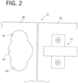
- FIG. 1 illustrates an example of a cabinet 2 to which a slide hinge 1 according to the invention is attached.
- the slide hinge 1 according to the invention is also commonly referred to as concealed hinge and attached between a door 2b side and a cabinet main body 2a side of the cabinet 2. As shown in FIGS.
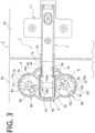
- the slide hinge 1 comprises a slide hinge main body 3 attached to the cabinet main body 2a side; a first coupling piece 4a and a second coupling piece 4b being a pair, wherein their respective one end portions are rotatably coupled to the slide hinge main body 3 via hinge pins 7a, 7b; a coupling case 5 of synthetic resin inserted into and fixed to an attaching hole 2c provided on a door 2b side, wherein respective other end portions of the first coupling piece 4a and the second coupling piece 4b are also rotatably coupled to the coupling case via a third hinge pin 7c and a fourth hinge pin 7d; attaching means 6a, 6b provided so as to be connected with the coupling case 5 in connecting holes 2d, 2e provided on the door 2b side in communication with the attaching hole 2c at its upper and lower positions; and a reinforcing frame body 10 attached to the coupling case 5 side by inserting the third hinge pin 7c and the fourth hinge pin 7d therein.
- the coupling case 5 is inserted into and fixed to the attaching hole 2c in a single operation using the attaching means 6a, 6b, so that it is possible that the coupling case 5 is attached, with no use of nails and attaching screws, etc., to a door 2b, on which such nails and attaching screws do not work, the durability of the coupling case 5 is enhanced by the reinforcing frame body 10.
- FIGS. 2 to 5 show a state of a slide hinge 1 attached to a cabinet 2, and especially as shown in FIG. 2 , a slide hinge main body 3 is detachably attached to a catch 11 (though detailed explanation is not made here) attached to a cabinet main body 2a side, and the coupling case 5 can be attached to the attaching hole 2c provided on the door 2b side, as well as to connecting holes 2d, 2e in a single operation via the attaching means 6a, 6b.
- the coupling case 5 is housed in the attaching hole 2c provided on the door 2b side, and the attaching means 6a, 6b connected with the coupling case 5 are inserted into the connecting holes 2d, 2e provided in communication with the attaching hole 2c at its upper and lower positions, and thus the attaching means 6a, 6b are fixed to the connecting holes 2d, 2e in a single operation; in this manner, the coupling case 5 is fixed to the door 2b in a single operation.
- the slide hinge main body 3 is shown as the one attachable and detachable in a single operation to the catch 11, but it can be also constructed so as to be attachable to the cabinet main body 2a side using attaching screws not shown.
- the catch 11 is a known art, so no explanation is made on its structure, as well as operation and effect in the following embodiments.
- the door 2b according to the embodiment is made up of thin dressing plywood boards 2g, 2g, 2g stuck on outer surfaces of a honeycomb cardboard core 2f; however, needless to say, the door 2b is not limited thereto, but also applicable as a door made up of other materials on which nails and attaching screws do not work.
- the slide hinge main body 3 is a pressed metallic piece, elongated and having the shape of U in cross section. Respective one end portions of the first coupling piece 4a and the second coupling piece 4b, both made of metal are rotatably coupled to a tip portion of the slide hinge main body 3 via the first hinge pin 7a and the second hinge pin 7b.
- the coupling case 5 is a moulded piece made of synthetic resin having a shape substantially of cup which comprises a bottom plate 5i, wherein a housing concave portion 5c is provided on its central portion for housing the first coupling piece 4a, the second coupling piece 4b and the tip portion side of the slide hinge main body 3, while the door 2b is closed relative to the cabinet main body 2a, as well as a coupling portion 5a for coupling the first coupling piece 4a and the second coupling piece 4b via the third hinge pin 7c; furthermore, the fourth hinge pin 7d and a coupling piece housing groove portion 5b slightly narrower than the housing concave portion 5c is provided on the coupling portion 5a.
- coupling holes 5d, 5e have their respective openings facing the coupling piece housing groove portion 5b, and other end portions of the first coupling piece 4a and the second coupling piece 4b are coupled to the coupling holes 5d, 5e via one hinge pin, that is the third hinge pin 7c and other hinge pin, that is the fourth hinge pin 7d, both folded in the shape of U.
- one hinge pin that is the third hinge pin 7c and other hinge pin, that is the fourth hinge pin 7d
- the reinforcing frame body 10 made of stainless steel such as SUS and having substantially the shape of U is attached to the housing concave portion 5c and the coupling piece housing groove portion 5b, with the third hinge pin 7c and the fourth hinge pin 7d as mentioned above being inserted into hinge pin coupling holes 10c, 10d provided on a base portion 10a of the reinforcing frame body.
- the reinforcing frame body 10 has substantially the shape of U and comprises a curved and narrow base portion 10a and a pair of slightly wider fixing portions 10b, 10b provided in connection with and in parallel to the base portion 10a; the hinge pin coupling holes 10c, 10d are provided on the base portion 10a, and a pair of first locking pieces 10e, 10e are provided on the base portion 10a of the fixing portions 10b, 10b; a pair of second locking pieces 10f, 10f are provided on their respective free end sides so as to protrude in a horizontal direction. Furthermore, locking holes 5g, 5g (only one is shown in FIG. 6 ) and locking holes 5h, 5h (shown in FIG.
- the attaching means 6a, 6b are composed of a pair of attaching case portions 8, 9 connected with an upper and lower portions of the coupling case 5 over partition walls 5f, 5f, and diameter enlarging means 12, 13 mounted on the attaching case portions 8, 9.
- the attaching case portions 8, 9 are both made of synthetic resin, that is the same material as the coupling case 5; each of them comprises three insertion holes 8a, 9a; 8a, 9a; 8a, 9a on its circumferential wall, and a locking hole 5h, 5h is provided on the side of the partition wall 5f, 5f between the coupling case 5 and the attaching case portions.
- each of locking holes 8c, 9c; 8c, 9c for locking a locking piece 18b, 19b of a cap 18, 19 inwardly are provided so as to protrude from each upper end edge of the attaching case portion 8, 9, and each bearing hole 8e, 9e is provided on a central portion in an axial direction of its each bottom plate 8d, 9d.
- An arc-shaped first guide hole 8f, 9f is provided to respectively surround each bearing hole 8e, 9e, and a projecting portion 8i, 9i is provided on one side on the central portion of the first guide hole 8f, 9f.
- the projecting portions 8i, 9i can be also provided on the side of the second guide holes 14g, 15g, either separately or one over the other.
- the housing concave portion 8g, 9g provided on the attaching case portions 8, 9 for housing the diameter enlarging means 12, 13 comprises a flat portion 8h, 9h on the side of a partition wall 5f, 5f as seen from a plane.
- the diameter enlarging means 12, 13 are respectively composed of a pair of locking plates 14, 15, a pair of operating plates 16, 17, and a pair of caps 18, 19.
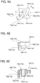
- Each locking plate 14, 15 is e.g. moulded of synthetic resin having mechanical strength such as ABS, has a disc shape in a plan view, and especially as shown in FIG. 8 , comprises a bearing hole 14b, 15b on an upper surface side of a central portion of its bottom plate portion 14a, 15a; furthermore, a boss portion 14c, 15c inserted into a bearing hole 8e, 9e provided on each attaching case portion 8, 9 is provided on a lower surface side, having an axis centre common with the bearing hole 14b, 15b.
- a locking piece 14e, 15e; 14e, 15e; 14e, 15e comprising each claw portion 14d, 15d; 14d, 15d; 14d, 15d, respectively erected at predetermined intervals and provided on respective tips is provided so as to protrude upward from an outer circumference of the bottom plate portion 14a, 15a; a second guide hole 14g, 15g in the arc shape is provided on a protruding piece 14f, 15f protruding in a direction of an identical plane from the bottom plate portion 14a, 15a; thus, when each locking plate 14, 15 is mounted in each attaching case portion 8, 9, each protruding piece 14f, 15f abuts against each flat portion 8h, 9h to prevent each locking plate 14, 15 from rotating, and each second guide hole 14g, 15g overlaps each first guide hole 8f, 9f.
- a locking piece 14e, 15e; 14e, 15e; 14e, 15e is moulded so as to fall inward, so that each claw portion 14d, 15d; 14d, 15d; 14d, 15d does not protrude outward from each insertion hole 8a, 9a; 8a, 9a; 8a, 9a of the attaching case portion 8, 9, but is housed inside to have elasticity.
- Each operating plate 16, 17 is preferably made of synthetic resin, and as shown in FIGS. 12 and 13 , comprises a plurality of pressurizing portions 16a, 17a; 16a, 17a; 16a, 17a provided so as to radially protrude from its outer circumference; an insertion hole 16c, 17c into which e.g. wrench is inserted is provided on a disc-shaped tool mounting portion 16b, 17b, and further a stopper piece 16e, 17e for passing through the second guide hole 14g, 15g provided on each locking plate 14, 15 and the first guide hole 8f, 9f provided on each attaching case portion 8, 9 is also provided downward from one side portion of the insertion hole.
- an axis portion 16d, 17d inserted into the bearing hole 14b, 15b provided on each locking plate 14, 15, having an axis centre in common with the tool mounting portion 16b, 17b, is also provided on a lower surface side.
- Each stopper piece 16e, 17e has its inner portion shaped to be a cavity 16g, 17g, so that it is structured so as to exhibit resistance to some degree, when it slides through the first guide hole 8f, 9f and the second guide hole 14g, 15g and abuts against the projecting portion 8i, 9i, as well as to deform to allow for its own passage.
- Each cap 18, 19 is also preferably made of synthetic resin, and in this embodiment, as shown in FIGS. 3 , 6 and 10 , it has substantially a disc shape; a bearing hole 18a, 19a is provided on its central portion in an axial direction; although not all is shown on each cap 18, 19, but as is apparent from comparison between the caps 18, 19 as they are shown, a locking piece 18b, 19b (only one is shown) inserted into and locked by the locking hole 8b, 9b provided on the attaching case portion 8, 9 is provided on one side on its circumference; furthermore, a pair of locking concave portions 18c, 19c; 18c, 19c locked by the locking pieces 8c, 9c; 8c, 9c provided on the attaching case portion 8, 9 are provided, each having an interval of 120 degrees from the locking piece 18b, 19b, on its outer circumference.
- a bearing hole 8e, 9e is provided on a central portion on the bottom plate 8d, 9d of each attaching case portion 8, 9.
- a boss portion 14c, 15c provided with a bearing hole 14b, 15b for housing the axis portion 16d, 17d of the operating plate 16, 17 is provided in the centre of its bottom plate 14a, 15a, and the boss portion 14c, 15c is inserted into and borne by the bearing hole 8e, 9e provided on a central portion on the bottom plate 8d, 9d of each attaching case portions 8, 9.
- six notches 14i, 15i are provided on a peripheral portion of the bottom portion 14a, 15a of the locking plate 14, 15, so as to sandwich base portions of respective locking pieces 14e, 15e; 14e, 15e; 14e, 15e.
- a triangle mark g, h and a circle mark i are respectively provided in vicinity of the tool mounting portion 16b, 17b of each operating plate 16, 17 and of the bearing hole 18a, 19a of each cap 18, 19.
- Each operating plate 16, 17 comprises the axis portion 16d, 17d extending downward from the tool mounting portion 16b, 17b; the tool mounting portion 16b, 17b is borne by the bearing hole 18a, 19a of each cap 18, 19, and a small diameter pivotally supporting portion 16f, 17f is inserted into and borne by the bearing hole 14b, 15b of each locking plate 14, 15, which assures a stable rotation movement with no axis deviation during rotation of the operating plate.
- the boss portion 14c, 15c of the locking plate 14, 15 is borne by the bearing hole 8e, 9e of each attaching case portion 8, 9; in this manner, it is possible that the claw portion 14d, 15d; 14d, 15d; 14d, 15d protrudes equally outward from each attaching case portions 8, 9 through each insertion hole 8a, 9a; 8a, 9a; 8a, 9a at the time of enlarging diameter, so that it has an advantage of stable attached state.
- each locking plate 14, 15 is inserted into the housing concave portion 8g, 9g, so as to align the straight portion 14h, 15h provided on the protruding piece 14f, 15f of the bottom plate portion 14a, 15a with the flat portion 8h, 9h of the housing concave portion 8g, 9g of each attaching case portion 8, 9.
- the boss portion 14c, 15c provided on the bottom plate portion 14a, 15a is fitted into the bearing hole 8e, 9e provided in the attaching case portion 8, 9, and thus mounted and fixed to it, without rotating neither to the right nor to the left.
- each operating plate 16, 17 is inserted into each locking piece 14e, 15e of the locking plate 14, 15 so as to align its pressurizing portion 16a, 17a between each locking piece 14e, 15e, as well as such that each stopper piece 16e, 17e can be inserted into the second guide hole 14g, 15g, so that the boss portion of the locking plate 14, 15 is inserted and housed into the bearing hole 14b, 15b provided on the locking plate.
- each cap 18, 19 is pushed downward, while its locking piece 18b, 19b is engaged with the locking hole 8b, 9b and its bearing hole 18a, 19a is aligned with the tool mounting portion 16b, 17b, so that each locking concave portion 18c, 19c; 18c, 19c is locked by the locking piece 8c, 9c; 8c, 9c to be mounted in each attaching case portion 8, 9.
- This is the procedure of installing the diameter enlarging means 12, 13. In this state, as shown in FIGS.
- each claw portion 14d, 15d; 14d, 15d; 14d, 15d of each locking plate 14, 15 does not protrude outward from the insertion hole 8a, 9a; 8a, 9a; 8a, 9a of the attaching case portion 8, 9; in this manner, the invention has an advantage that it has neat appearance, and that it is easy to insert the coupling case 5 and the attaching case portion 8, 9 into the attaching hole 2c and the connecting holes 2d, 2e provided on the door 2b of the cabinet 2 of Embodiment 1, at its attachment.
- the invention has an advantage that the attaching case portion 8, 9 can be easily detached from the attaching hole 2c and the connecting holes 2d, 2e, together with the coupling case 5.
- each claw portion 14d, 15d; 14d, 15d; 14d, 15d is structured to be fitted into the insertion hole 8a, 9a; 8a, 9a; 8a, 9a, not to protrude outward from the insertion hole; in this manner, its insertion position is stable.
- the stopper piece 16e, 17e of the operating plate 16, 17 is inserted into the second guide hole 14g, 15g and the first guide hole 8f, 9f, as one overlaps the other, in order that it is placed toward their start-end portion.
- each pressurizing portion 16a, 17a; 16a, 17a; 16a, 17a is placed between respective claw portions 14d, 15d; 14d, 15d; 14d, 15d.
- the cap 18, 19 is placed on the top of the attaching case portion 8, 9 and locked thereto as described above, then the assembly is completed.
- the triangle mark g, g provided on each tool mounting portion 16b, 17b of the operating plate 16, 17 points to the circle mark i, i provided on the cap 18, 19 at the time of completion of assembly.
- the slide hinge main body 3 is pushed into the catch 11 attached to the cabinet main body 2a, so that the slide hinge can be attached to the cabinet in a single operation.
- the attaching piece not shown of known structure is provided on the slide hinge main body 3, and that this attaching piece is attached via the attaching screw.
- the attaching case portion 8, 9 constituting the coupling case 5 and the attaching means 6a, 6b is inserted into the attaching hole 2c and the connecting holes 2d, 2e provided on the door 2b.
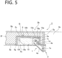
- a state of the attaching case portion 8, 9 as inserted into the connecting holes 2d or 2e is shown in cross section in FIG. 5 .
- each pressurizing portion 16a, 17a; 16a, 17a; 16a, 17a pushes outward each claw portion 14d, 15d; 14d, 15d; 14d, 15d of each locking piece 14e, 15e; 14e, 15e; 14e, 15e of the locking plate 14, 15, so that the claw portion 14d, 15d; 14d, 15d; 14d, 15d protrudes outward through each insertion hole 8a, 9a; 8a, 9a; 8a, 9a of each attaching case portion 8, 9, and they bites into the circumferential wall of the connecting holes 2d or 2e of the
- the stopper means 20, 21 is provided for preventing the operating plate 16, 17 from excessively rotating at the time of rotating the operating plate 16, 17.
- the stopper means 20, 21 are composed of the stopper piece 16e, 17e provided on the operating plate 16, 17, the second guide hole 14g, 15g provided on each locking piece 14e, 15e and the first guide hole 8f, 9f provided on each attaching case portion 8, 9, wherein the stopper piece 16e, 17e is fitted into the second guide hole and the first guide hole; when the stopper piece 16e, 17e moves from respective start-end portions to respective terminal end portions of the first guide hole 8f, 9f and the second guide hole 14g, 15g to stop at the terminal end portions, the claw portion 14d, 15d; 14d, 15d; 14d, 15d protrudes most outward, to bite into the circumferential wall of the connecting holes 2d, 2e, as shown in FIG.
- the stopper means 20, 21 is structured by providing projecting portions on the pressurizing portions 16a, 17a; 16a, 17a; 16a, 17a of the operating plate 16, 17, at the positions where the operating plate 16, 17 abuts against each locking piece 14e, 15e; 14e, 15e; 14e, 15e, when it is rotated at a predetermined angle.
- the stopper means is structured as described above, its structure is simplified, and the costs are reduced.
- the invention is constructed as described in the foregoing, it is suitably used as a slide hinge made e.g. of a core of honeycomb cardboard and applicable to cabinets intended for use in common households or offices, as well as a cabinet using such a slide hinge.
Description
- The invention relates to a slide hinge also referred to as a concealed hinge which is used for opening and closing a door in furniture such as cabinets intended for use in common households or offices; the invention also relates to a cabinet using such a slide hinge.
- Some sorts of furniture, such as storage shed, large furniture, furnishing and storage box, are installed in common households, while other sorts are used in the office. For both categories of furniture, a cabinet is a representative item. The furniture as above described, and in particular cabinet, commonly uses a slide hinge structured as described in
Japanese Laid-Open Patent Application No. 2003-367 Japanese Utility Model Registration No. 3090408 - If a conventional slide hinge as above described includes a coupling case attached to a door of wooden solid material, attaching screws well fasten the coupling case onto the door, so that the door will not easily escape from the coupling case; in recent years however, a different type of doors is increasingly used, wherein the door comprises a core, e.g. honeycomb cardboard, on which attaching screws do not work well, and thin dressing boards stuck onto the both surfaces of the core.
- Even if an attempt is made in this case to fix a coupling case of a slide case (which is to be attached to the door) onto a door with a core of honeycomb cardboard, on which screws do not work well, there has been a problem in that the coupling case cannot be firmly fixed to the door or escapes from the door during usage after fixation.
- Therefore, the Applicant's affiliated company, Katoh Electrical Machinery, proposed an inexpensive slide hinge configured such that a coupling case can be easily attached even to a door or a cabinet main body which uses a core of honeycomb cardboard, on which screws do not work, and a fear of escape following attachment is eliminated (
Japanese Laid-Open Patent Application No. 2014-88755 -
US 2014/096343 A1 discloses a slide hinge comprising a slide hinge main body, a coupling case of synthetic resin, and a coupling piece for openably and closably connecting said slide hinge main body and said coupling case via a hinge pin, wherein an attaching means is provided which is composed of a pair of attaching case portions continuously provided integrally with both side portions of the coupling case, and of diameter enlarging means provided in each of the attaching case portions. A further slide hinge is known, e.g., fromUS 4 270 240 A . - An object of the invention is therefore to provide a slide hinge configured such that a coupling case can be attached to a honeycomb board in a single operation, wherein a fear of problems in terms of strength is eliminated, even if a coupling case composed of the coupling case and the attaching means are made of synthetic resin, as well as a cabinet using such a slide hinge.
- To achieve the above-mentioned object, the invention provides a slide hinge according to
claim 1. - Further embodiments are described in the dependent claims.
- The invention is constructed as described in the foregoing, so that in an invention according to
claim 1, a slide hinge comprises a slide hinge main body attached to a cabinet main body, a coupling case inserted into and fixed to an attaching hole provided on a door, and a coupling piece for openably and closably coupling the cabinet main body and the coupling case via a hinge pin, wherein, in inserting and fixing the coupling case to an attaching hole provided on the side of the door made up of honeycomb cardboard, on which screws do not work, attaching case portions also made up of synthetic resin are connected with both sides of the coupling piece, diameter enlarging means are provided in the attaching case portions, and a reinforcing frame body is provided by inserting the hinge pin into the coupling case; in this manner, the coupling case can be firmly fixed to the attaching hole with no use of attaching screws and nails, so that a risk of escape following attachment is eliminated; furthermore, the strength of the coupling case can be enhanced by the reinforcing frame body, as well as its durability. - In an invention according to
claim 2, when tools such as wrench are inserted one by one into a tool mounting portion provided on each of operating plates and the operating plates are thus rotated, pressurizing portions rotating together pushes a claw portion provided on a locking piece of each of locking plates out of attaching case portions, and the claw portion provided on each of the locking pieces bites into a circumferential wall of the connecting hole; in this manner, the coupling case can be firmly fixed to the attaching hole with no use of attaching screws and nails, so that a risk of escape following attachment is eliminated; furthermore, the strength of the coupling case can be enhanced by the reinforcing frame body, as well as its durability. - If the invention is constructed as in
claim 3, in addition to the operation and effect which it has according toclaim 2, stopper means of each of locking plates move together with a rotation of operating plates to stop the rotation of the operating plates; in this manner, the rotation of pressurizing portions can be stopped when each claw portion of each of locking pieces bites into a circumferential wall of the connecting hole, so that it is possible to prevent the pressurizing portions from excessively rotating. - If the invention is constructed as in claim 4, in addition to the operation and effect which it has according to
claim 2, this effectively prevents operating plates from return to the original position, when the diameter of the claw portions is enlarged. - If the invention is constructed as in
claim 5, it has the operation and effect that the claw portion of the locking piece is not an obstacle to mounting the attaching case portion to the connecting hole. - If the invention is constructed as in claim 6, it has the operation and effect that the strength of a coupling case can be enhanced by a reinforcing frame body, as well as a durability of a slide hinge, in a simple structure.
- If the invention is constructed as in
claim 7, any of the above-mentioned inventions is applicable to a cabinet comprising the coupling case of the slide hinge attached on a cabinet main body using a board, wherein the board is made up of thin dressing boards being stuck onto the both surfaces of the honeycomb cardboard core. - And then, if the invention is constructed as in
claim 7, the honeycomb door can be easily and firmly attached to the cabinet main body. -
-
FIG. 1 shows a perspective view illustrating an example of a cabinet to which a slide hinge according to the invention is attached; -
FIG. 2 shows an elevation view illustrating a state of a part of a cabinet to which a slide hinge according to the invention is attached; -
FIG. 3 shows an elevation view illustrating a state of a cabinet to which a slide hinge according to the invention is attached, wherein a door is opened; -
FIG. 4 shows a slide hinge according to the invention,FIG. 4A being a plan view illustrating a state shown inFIG. 3 in a partial cross section, andFIG. 4B - a plan view a state shown inFIG. 4A , wherein a door is closed, also in a partial cross section; -
FIG. 5 shows a longitudinal cross section of a part including a coupling case as shown inFIG. 4 ; -
FIG. 6 shows an exploded perspective view of a part including a coupling case and attaching means of a slide hinge according to the invention; -
FIG. 7 shows an elevation view of a part including a coupling case and attaching case portions of a slide hinge according to the invention; -
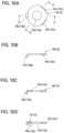
FIG. 8 shows a locking plate of a slide hinge according to the invention,FIG. 8A being its plan view,FIG. 8B - its left-hand side view, andFIG. 8C - a cross section ofFIG. 8A in line A-A; -
FIG. 9 shows an operating plate of a slide hinge according to the invention,FIG. 9A being its plan view,FIG. 9B - its elevation view, andFIG. 9C - a cross section ofFIG. 9A in line B-B; -
FIG. 10 shows a cap of a slide hinge according to the invention,FIG. 10A being its plan view,FIG. 10B - its elevation view,FIG. 10C - a cross section ofFIG. 10A in line C-C andFIG. 10D - a cross section ofFIG. 10A in line D-D; -
FIG. 11 shows a reinforcing frame body according to the invention,FIG. 11A being its elevation view,FIG. 11B - its plan view, andFIG. 11C - its right-hand side view; -
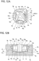
FIG. 12 illustrates a state of attaching means of a slide hinge according to the invention before the operation,FIG. 12A being its plan view, andFIG. 12B - its longitudinal cross section; and -
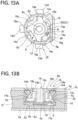
FIG. 13 illustrates a state of attaching means of a slide hinge according to the invention after the completion of the operation,FIG. 13A being its plan view, andFIG. 13B - its longitudinal cross section. - In the following, the best modes for implementing the invention are described based the drawings. The best modes for implementing the invention have structure as shown in the following embodiments, namely: attaching
means coupling case 5 side of aslide hinge 1, wherein the attachingmeans coupling case 5 are both made of synthetic resin, and athird hinge pin 7c and afourth hinge pin 7d are inserted through thecoupling case 5 to attach a reinforcing frame body thereto; in this manner, these best modes ensure that thecoupling case 5 can be fixed to adoor 2b side or to a cabinetmain body 2a side even without using attaching screws, so that a reinforcing effect of the coupling case can be enhanced, as well as its durability. In the following, reference is made to an embodiment of thecoupling case 5 attached to thedoor 2b side, but needless to say, the invention is also applicable to thecoupling case 5 attached to the cabinetmain body 2a side. Normally two such slide hinges 1, one above and one below, are used for asingle door 2b, but since both have an identical structure, so in the following, reference is made to one slide hinge only. -
FIG. 1 illustrates an example of acabinet 2 to which aslide hinge 1 according to the invention is attached. Theslide hinge 1 according to the invention is also commonly referred to as concealed hinge and attached between adoor 2b side and a cabinetmain body 2a side of thecabinet 2. As shown inFIGS. 3 to 5 of the attached drawings, theslide hinge 1 comprises a slide hingemain body 3 attached to the cabinetmain body 2a side; afirst coupling piece 4a and asecond coupling piece 4b being a pair, wherein their respective one end portions are rotatably coupled to the slide hingemain body 3 viahinge pins coupling case 5 of synthetic resin inserted into and fixed to an attachinghole 2c provided on adoor 2b side, wherein respective other end portions of thefirst coupling piece 4a and thesecond coupling piece 4b are also rotatably coupled to the coupling case via athird hinge pin 7c and afourth hinge pin 7d; attachingmeans coupling case 5 in connectingholes door 2b side in communication with the attachinghole 2c at its upper and lower positions; and a reinforcingframe body 10 attached to thecoupling case 5 side by inserting thethird hinge pin 7c and thefourth hinge pin 7d therein. Thecoupling case 5 is inserted into and fixed to the attachinghole 2c in a single operation using the attachingmeans coupling case 5 is attached, with no use of nails and attaching screws, etc., to adoor 2b, on which such nails and attaching screws do not work, the durability of thecoupling case 5 is enhanced by the reinforcingframe body 10. -
FIGS. 2 to 5 show a state of aslide hinge 1 attached to acabinet 2, and especially as shown inFIG. 2 , a slide hingemain body 3 is detachably attached to a catch 11 (though detailed explanation is not made here) attached to a cabinetmain body 2a side, and thecoupling case 5 can be attached to the attachinghole 2c provided on thedoor 2b side, as well as to connectingholes means coupling case 5, thecoupling case 5 is housed in the attachinghole 2c provided on thedoor 2b side, and the attachingmeans coupling case 5 are inserted into the connectingholes hole 2c at its upper and lower positions, and thus the attachingmeans holes coupling case 5 is fixed to thedoor 2b in a single operation. In the meantime, the slide hingemain body 3 is shown as the one attachable and detachable in a single operation to thecatch 11, but it can be also constructed so as to be attachable to the cabinetmain body 2a side using attaching screws not shown. Thecatch 11 is a known art, so no explanation is made on its structure, as well as operation and effect in the following embodiments. - Especially as shown in
FIG. 4 , thedoor 2b according to the embodiment is made up of thindressing plywood boards honeycomb cardboard core 2f; however, needless to say, thedoor 2b is not limited thereto, but also applicable as a door made up of other materials on which nails and attaching screws do not work. - As seen in the drawings, the slide hinge
main body 3, thefirst coupling piece 4a, thesecond coupling piece 4b and thecoupling case 5 of theslide hinge 1 are not specifically limited in their structure, but various known parts can be used for these elements. In the meantime, reference is made to the one according to the embodiment: the slide hingemain body 3 is a pressed metallic piece, elongated and having the shape of U in cross section. Respective one end portions of thefirst coupling piece 4a and thesecond coupling piece 4b, both made of metal are rotatably coupled to a tip portion of the slide hingemain body 3 via thefirst hinge pin 7a and thesecond hinge pin 7b. - Especially as shown in
FIGS. 4 to 7 , thecoupling case 5 is a moulded piece made of synthetic resin having a shape substantially of cup which comprises abottom plate 5i, wherein a housingconcave portion 5c is provided on its central portion for housing thefirst coupling piece 4a, thesecond coupling piece 4b and the tip portion side of the slide hingemain body 3, while thedoor 2b is closed relative to the cabinetmain body 2a, as well as acoupling portion 5a for coupling thefirst coupling piece 4a and thesecond coupling piece 4b via thethird hinge pin 7c; furthermore, thefourth hinge pin 7d and a coupling piecehousing groove portion 5b slightly narrower than the housingconcave portion 5c is provided on thecoupling portion 5a. On thecoupling portion 5a,coupling holes housing groove portion 5b, and other end portions of thefirst coupling piece 4a and thesecond coupling piece 4b are coupled to thecoupling holes third hinge pin 7c and other hinge pin, that is thefourth hinge pin 7d, both folded in the shape of U. Especially as shown inFIGS. 3 ,6 and11 , the reinforcingframe body 10 made of stainless steel such as SUS and having substantially the shape of U is attached to the housingconcave portion 5c and the coupling piecehousing groove portion 5b, with thethird hinge pin 7c and thefourth hinge pin 7d as mentioned above being inserted into hingepin coupling holes base portion 10a of the reinforcing frame body. - Especially as shown in
FIGS. 3 ,6 and11 , the reinforcingframe body 10 has substantially the shape of U and comprises a curved andnarrow base portion 10a and a pair of slightlywider fixing portions base portion 10a; the hingepin coupling holes base portion 10a, and a pair offirst locking pieces base portion 10a of the fixingportions second locking pieces holes FIG. 6 ) and lockingholes FIG. 7 ) in which thesecond locking pieces first locking pieces frame body 10 are respectively inserted and fixed are provided on the housingconcave portion 5c of thecoupling case 5; a pair of first abuttingportions coupling case 5, and second abuttingportions - As shown in
FIGS. 3 to 7 , the attachingmeans case portions coupling case 5 overpartition walls diameter enlarging means case portions case portions coupling case 5; each of them comprises threeinsertion holes locking hole partition wall coupling case 5 and the attaching case portions. Two each of lockingholes locking piece cap case portion bearing hole bottom plate first guide hole bearing hole portion first guide hole portions second guide holes concave portion case portions diameter enlarging means flat portion partition wall - The
diameter enlarging means plates operating plates caps plate FIG. 8 , comprises abearing hole bottom plate portion boss portion bearing hole case portion bearing hole locking piece claw portion bottom plate portion second guide hole piece bottom plate portion plate case portion piece flat portion plate second guide hole first guide hole FIG. 8 , alocking piece claw portion insertion hole case portion - Each operating
plate FIGS. 12 and13 , comprises a plurality of pressurizingportions insertion hole tool mounting portion stopper piece second guide hole plate first guide hole case portion axis portion bearing hole plate tool mounting portion stopper piece cavity first guide hole second guide hole portion - Each
cap FIGS. 3 ,6 and10 , it has substantially a disc shape; abearing hole cap caps locking piece hole case portion concave portions pieces case portion locking piece - In the meantime, a
bearing hole bottom plate case portion plate boss portion bearing hole axis portion plate bottom plate boss portion bearing hole bottom plate case portions notches bottom portion plate respective locking pieces - A triangle mark g, h and a circle mark i are respectively provided in vicinity of the
tool mounting portion plate bearing hole cap plate axis portion tool mounting portion tool mounting portion bearing hole cap portion bearing hole plate - Still further, the
boss portion plate bearing hole case portion claw portion case portions insertion hole - In the following, reference is made to the procedure of installing the
diameter enlarging means slide hinge 1 according to the invention in each attachingcase portion plate concave portion straight portion piece bottom plate portion flat portion concave portion case portion boss portion bottom plate portion bearing hole case portion plate piece plate portion piece stopper piece second guide hole plate bearing hole cap locking piece locking hole bearing hole tool mounting portion concave portion locking piece case portion diameter enlarging means FIGS. 12A and 12B , eachclaw portion plate insertion hole case portion coupling case 5 and the attachingcase portion hole 2c and the connectingholes door 2b of thecabinet 2 ofEmbodiment 1, at its attachment. Moreover, when thecoupling case 5 of theslide hinge 1 is detached from thedoor 2b, the operatingplate claw portion plate insertion hole case portion case portion hole 2c and the connectingholes coupling case 5. - In assembly of the locking
plate plate cap case portion plate case portion second guide hole first guide hole claw portion insertion hole stopper piece plate second guide hole first guide hole portion respective claw portions cap case portion tool mounting portion plate cap - At the time of attachment of the
slide hinge 1 to thecabinet 2, first, the slide hingemain body 3 is pushed into thecatch 11 attached to the cabinetmain body 2a, so that the slide hinge can be attached to the cabinet in a single operation. Of course, it is also possible in this regard that the attaching piece not shown of known structure is provided on the slide hingemain body 3, and that this attaching piece is attached via the attaching screw. Next, the attachingcase portion coupling case 5 and the attachingmeans hole 2c and the connectingholes door 2b. A state of the attachingcase portion holes FIG. 5 . - Then, the tools such as wrench are inserted one by one into the
insertion hole tool mounting portion plate plate cap plate cap portion claw portion piece plate claw portion insertion hole case portion holes door 2b; in this manner, thecoupling case 5 is firmly fixed to thedoor 2b side. - In the meantime, the stopper means 20, 21 is provided for preventing the operating
plate plate FIGS. 6 and9 , the stopper means 20, 21 are composed of thestopper piece plate second guide hole piece first guide hole case portion stopper piece stopper piece first guide hole second guide hole claw portion holes FIG. 13 . When returning the rotated operatingplate stopper piece first guide hole second guide hole portion stopper piece - Furthermore, it is possible that the stopper means 20, 21 is structured by providing projecting portions on the pressurizing
portions plate plate piece - Since the invention is constructed as described in the foregoing, it is suitably used as a slide hinge made e.g. of a core of honeycomb cardboard and applicable to cabinets intended for use in common households or offices, as well as a cabinet using such a slide hinge.
Claims (7)
- A slide hinge (1) comprising a slide hinge main body (3), a coupling case (5) of synthetic resin, and a coupling piece (4a, 4b) for openably and closably connecting said slide hinge main body (3) and said coupling case (5) via hinge pins (7c, 7d),wherein said coupling case (5) has a coupling piece housing groove portion (5b), a housing concave portion (5c) and attaching means (6a, 6b),wherein said attaching means (6a, 6b) are composed of a pair of attaching case portions (8, 9) continuously provided integrally with both side portions of the coupling case (5), and diameter enlarging means (12, 13) provided in each of the attaching case portions (8, 9),characterised in thatsaid coupling case (5) has a reinforcing frame body (10) that has substantially the shape of U and comprises a curved and narrow base portion (10a) and a pair of slightly wider fixing portions (10b, 10b) provided in connection with and in parallel to the base portion (10a);hinge pin coupling holes (10c, 10d) are provided on the base portion (10a), a pair of first locking pieces (10e, 10e) are provided on the base portion (10a) of the fixing portions (10b, 10b); a pair of second locking pieces (10f, lOf) are provided on their respective free end sides so as to protrude in a horizontal direction;a pair of first abutting portions (10g, 10g) for abutting a bottom portion of the coupling case (5), and second abutting portions (10h, 10h) are respectively provided; andsaid hinge pins (7c, 7d) are inserted in said hinge pin coupling holes (10c, 10d), said pair of first locking pieces (10e, 10e) are inserted in locking holes (5h, 5h) of said coupling case, and said second locking pieces (10f, 10f) are inserted in saiel locking holes (5g, 5g) on the housing concave portion (5c) of said coupling case (5).
- The slide hinge according to claim 1, characterised in thatthe diameter enlarging means (12, 13) comprise locking plate (14, 15) having locking pieces (14e, 15e) provided claw portions (14d, 15d) so as to protrude outside from insertion holes (8a, 9a) of said attaching case portions (8, 9), andthe locking pieces (14e, 15e) are imparted with elasticity, operating plates (16, 17) having a plurality of pressurizing portions (16a, 17a) rotatably housed in the locking plates (14, 15) and a tool mounting portions (16b, 17b) toward a tip on each central portion, wherein the pressurizing portions (16a, 17a) are pushing the claw portions (14d, 15d) to outer direction and a rotation angle of the operating plates (16, 17) are controlled by stopper means (20, 21) within a predetermined range, andcaps (18, 19) having a bearing hole (18a, 19a) for pivotally supporting the tool mounting portions (16b, 17b), on a central portion of the caps (18, 19), wherein the caps (18, 19) are attached to the attaching case portions (8, 9) so as to be attachable and detachable.
- The slide hinge according to claim 2, characterised in that
the stopper means (20, 21) of each of the operating plates (16, 17) are composed of stopper pieces (16e, 17e) passing through a first guide hole (8e, 9e) provided on each of the locking plates (14, 15) and a second guide hole (14g, 15g) provided on each of the attaching case portions (8, 9) so as to overlap the first guide hole (8e, 9e). - The slide hinge according to claim 3, characterised in that
projecting portions (8i, 9i) for controlling a slide of the stopper pieces (16e, 17e) are provided on one or both of the first guide hole (8e, 9e) and the second guide hole (14g, 15g). - The slide hinge according to one of claims 2 to 4, characterised in that
each claw portion (14d, 15d) of each of the locking plates (14,15) is normally housed inside each of the attaching case portions (8, 9). - The slide hinge according to one of claims 1 characterised in that
the reinforcing frame body (10) further has the pair of first locking pieces (10e, 10e) provided on said fixing portions (10b, 10b), the pair of first abutting portions (10g, 10g) for abutting a bottom portion (5i) of the coupling case (5), and the pair of second abutting portions (10h, 10h) for abutting a bottom portion (5i) of the coupling case (5). - A cabinet characterised in that
a slide hinge (1) according to one of claims 1 to 6 is attached thereto.
Applications Claiming Priority (1)
| Application Number | Priority Date | Filing Date | Title |
|---|---|---|---|
| JP2017164880A JP7244892B2 (en) | 2017-08-29 | 2017-08-29 | sliding hinges and cabinets |
Publications (2)
| Publication Number | Publication Date |
|---|---|
| EP3450666A1 EP3450666A1 (en) | 2019-03-06 |
| EP3450666B1 true EP3450666B1 (en) | 2024-01-17 |
Family
ID=63294076
Family Applications (1)
| Application Number | Title | Priority Date | Filing Date |
|---|---|---|---|
| EP18189307.4A Active EP3450666B1 (en) | 2017-08-29 | 2018-08-16 | Slide hinge and cabinet |
Country Status (2)
| Country | Link |
|---|---|
| EP (1) | EP3450666B1 (en) |
| JP (1) | JP7244892B2 (en) |
Families Citing this family (2)
| Publication number | Priority date | Publication date | Assignee | Title |
|---|---|---|---|---|
| AT519915B1 (en) * | 2017-05-11 | 2020-11-15 | Blum Gmbh Julius | Dowels for fastening hardware components |
| WO2021173090A1 (en) * | 2020-02-27 | 2021-09-02 | Samet Kalip Ve Madeni̇ Eşya San Ti̇c. A.Ş | Hinge |
Family Cites Families (8)
| Publication number | Priority date | Publication date | Assignee | Title |
|---|---|---|---|---|
| DE7725760U1 (en) * | 1977-08-19 | 1978-02-23 | Fa. Richard Heinze, 4900 Herford | FITTING, IN PARTICULAR HINGE CUP FOR FURNITURE HINGES |
| JPS5819364Y2 (en) * | 1981-10-08 | 1983-04-21 | テクトロニックス・インコ−ポレイテッド | Fastener |
| JP2003000367A (en) | 2001-06-26 | 2003-01-07 | Sekisui Chem Co Ltd | Sink with counter |
| JP3090408U (en) * | 2002-05-31 | 2002-12-13 | 福隆尖端科技股▲分▼有限公司 | Automatic closing slide hinge |
| JP4291037B2 (en) * | 2003-05-07 | 2009-07-08 | スガツネ工業株式会社 | Slide hinge |
| CN103596842B (en) | 2011-06-17 | 2016-02-03 | L-3通信磁电机股份有限公司 | The driver element of aircraft running gear wheel |
| JP6168940B2 (en) * | 2012-10-04 | 2017-07-26 | 加藤電機株式会社 | Slide hinge |
| DE102014113714A1 (en) * | 2014-09-23 | 2016-03-24 | Samet Kalip Ve Maden Esya San. Ve Tic. A.S. | hinge |
-
2017
- 2017-08-29 JP JP2017164880A patent/JP7244892B2/en active Active
-
2018
- 2018-08-16 EP EP18189307.4A patent/EP3450666B1/en active Active
Also Published As
| Publication number | Publication date |
|---|---|
| EP3450666A1 (en) | 2019-03-06 |
| JP7244892B2 (en) | 2023-03-23 |
| JP2019044342A (en) | 2019-03-22 |
Similar Documents
| Publication | Publication Date | Title |
|---|---|---|
| US8938857B2 (en) | Slide hinge | |
| US8276241B2 (en) | Hinge | |
| US4912349A (en) | Pivotally adjustable electric hand tool | |
| EP3450666B1 (en) | Slide hinge and cabinet | |
| US6200062B1 (en) | Furniture combination with connector device | |
| US8410363B1 (en) | Tamper proof wallplate | |
| US10492609B2 (en) | Mechanism to prevent sliding for cabinet drawers | |
| US6434791B1 (en) | Hinges | |
| US4549831A (en) | Set of joining hardware | |
| JPH04265386A (en) | Hinge frame | |
| EP3379010A1 (en) | Slide hinge and cabinet using the same | |
| US6257631B1 (en) | Draw latch | |
| US6991271B2 (en) | Latch assembly with adjustable backset | |
| EP0548489B1 (en) | A sheet metal door panel with hinge case | |
| US5095583A (en) | Folding-arm bearing for an oscillating-swinging leaf | |
| US5887316A (en) | One-pin furniture hinge with adjusting system | |
| CN108643775B (en) | Door opening limiting part | |
| CN211517311U (en) | Ratchet wrench | |
| CN210320811U (en) | Hinge assembly for refrigeration appliance and refrigeration appliance | |
| CN109373685B (en) | Refrigerator with a door | |
| US20080204979A1 (en) | Enclosure Assembly | |
| CN211874139U (en) | Handle structure and handle structure group | |
| US7350838B2 (en) | Catch or locking element | |
| KR101932155B1 (en) | A cabinet | |
| JP6494542B2 (en) | Orito |
Legal Events
| Date | Code | Title | Description |
|---|---|---|---|
| PUAI | Public reference made under article 153(3) epc to a published international application that has entered the european phase |
Free format text: ORIGINAL CODE: 0009012 |
|
| STAA | Information on the status of an ep patent application or granted ep patent |
Free format text: STATUS: THE APPLICATION HAS BEEN PUBLISHED |
|
| AK | Designated contracting states |
Kind code of ref document: A1 Designated state(s): AL AT BE BG CH CY CZ DE DK EE ES FI FR GB GR HR HU IE IS IT LI LT LU LV MC MK MT NL NO PL PT RO RS SE SI SK SM TR |
|
| AX | Request for extension of the european patent |
Extension state: BA ME |
|
| STAA | Information on the status of an ep patent application or granted ep patent |
Free format text: STATUS: REQUEST FOR EXAMINATION WAS MADE |
|
| 17P | Request for examination filed |
Effective date: 20190906 |
|
| RBV | Designated contracting states (corrected) |
Designated state(s): AL AT BE BG CH CY CZ DE DK EE ES FI FR GB GR HR HU IE IS IT LI LT LU LV MC MK MT NL NO PL PT RO RS SE SI SK SM TR |
|
| STAA | Information on the status of an ep patent application or granted ep patent |
Free format text: STATUS: EXAMINATION IS IN PROGRESS |
|
| 17Q | First examination report despatched |
Effective date: 20220601 |
|
| P01 | Opt-out of the competence of the unified patent court (upc) registered |
Effective date: 20230530 |
|
| GRAP | Despatch of communication of intention to grant a patent |
Free format text: ORIGINAL CODE: EPIDOSNIGR1 |
|
| STAA | Information on the status of an ep patent application or granted ep patent |
Free format text: STATUS: GRANT OF PATENT IS INTENDED |
|
| RIC1 | Information provided on ipc code assigned before grant |
Ipc: E05D 9/00 20060101ALN20230706BHEP Ipc: E05D 3/14 20060101ALN20230706BHEP Ipc: E05D 5/02 20060101AFI20230706BHEP |
|
| INTG | Intention to grant announced |
Effective date: 20230809 |
|
| GRAS | Grant fee paid |
Free format text: ORIGINAL CODE: EPIDOSNIGR3 |
|
| GRAA | (expected) grant |
Free format text: ORIGINAL CODE: 0009210 |
|
| STAA | Information on the status of an ep patent application or granted ep patent |
Free format text: STATUS: THE PATENT HAS BEEN GRANTED |
|
| AK | Designated contracting states |
Kind code of ref document: B1 Designated state(s): AL AT BE BG CH CY CZ DE DK EE ES FI FR GB GR HR HU IE IS IT LI LT LU LV MC MK MT NL NO PL PT RO RS SE SI SK SM TR |
|
| REG | Reference to a national code |
Ref country code: GB Ref legal event code: FG4D |
|
| REG | Reference to a national code |
Ref country code: CH Ref legal event code: EP |
|
| REG | Reference to a national code |
Ref country code: DE Ref legal event code: R096 Ref document number: 602018064190 Country of ref document: DE |
|
| REG | Reference to a national code |
Ref country code: IE Ref legal event code: FG4D |