EP3450624A1 - Refiner segment for a fiber refiner - Google Patents
Refiner segment for a fiber refiner Download PDFInfo
- Publication number
- EP3450624A1 EP3450624A1 EP18446502.9A EP18446502A EP3450624A1 EP 3450624 A1 EP3450624 A1 EP 3450624A1 EP 18446502 A EP18446502 A EP 18446502A EP 3450624 A1 EP3450624 A1 EP 3450624A1
- Authority
- EP
- European Patent Office
- Prior art keywords
- refiner
- refiner segment
- segment
- refining
- steam
- Prior art date
- Legal status (The legal status is an assumption and is not a legal conclusion. Google has not performed a legal analysis and makes no representation as to the accuracy of the status listed.)
- Granted
Links
Images



Classifications
-
- D—TEXTILES; PAPER
- D21—PAPER-MAKING; PRODUCTION OF CELLULOSE
- D21B—FIBROUS RAW MATERIALS OR THEIR MECHANICAL TREATMENT
- D21B1/00—Fibrous raw materials or their mechanical treatment
- D21B1/04—Fibrous raw materials or their mechanical treatment by dividing raw materials into small particles, e.g. fibres
- D21B1/12—Fibrous raw materials or their mechanical treatment by dividing raw materials into small particles, e.g. fibres by wet methods, by the use of steam
- D21B1/14—Disintegrating in mills
-
- D—TEXTILES; PAPER
- D21—PAPER-MAKING; PRODUCTION OF CELLULOSE
- D21D—TREATMENT OF THE MATERIALS BEFORE PASSING TO THE PAPER-MAKING MACHINE
- D21D1/00—Methods of beating or refining; Beaters of the Hollander type
- D21D1/20—Methods of refining
- D21D1/30—Disc mills
- D21D1/303—Double disc mills
-
- D—TEXTILES; PAPER
- D21—PAPER-MAKING; PRODUCTION OF CELLULOSE
- D21D—TREATMENT OF THE MATERIALS BEFORE PASSING TO THE PAPER-MAKING MACHINE
- D21D1/00—Methods of beating or refining; Beaters of the Hollander type
- D21D1/20—Methods of refining
- D21D1/30—Disc mills
- D21D1/306—Discs
-
- B—PERFORMING OPERATIONS; TRANSPORTING
- B02—CRUSHING, PULVERISING, OR DISINTEGRATING; PREPARATORY TREATMENT OF GRAIN FOR MILLING
- B02C—CRUSHING, PULVERISING, OR DISINTEGRATING IN GENERAL; MILLING GRAIN
- B02C7/00—Crushing or disintegrating by disc mills
- B02C7/11—Details
- B02C7/12—Shape or construction of discs
-
- D—TEXTILES; PAPER
- D21—PAPER-MAKING; PRODUCTION OF CELLULOSE
- D21D—TREATMENT OF THE MATERIALS BEFORE PASSING TO THE PAPER-MAKING MACHINE
- D21D1/00—Methods of beating or refining; Beaters of the Hollander type
- D21D1/20—Methods of refining
-
- D—TEXTILES; PAPER
- D21—PAPER-MAKING; PRODUCTION OF CELLULOSE
- D21D—TREATMENT OF THE MATERIALS BEFORE PASSING TO THE PAPER-MAKING MACHINE
- D21D1/00—Methods of beating or refining; Beaters of the Hollander type
- D21D1/20—Methods of refining
- D21D1/30—Disc mills
Definitions
- the present invention generally relates to refining of fibrous material in a fiber refiner, and more particularly to feed variations during the refining process.
- Refiners used for refining fibrous material, such as wood chips, into pulp typically comprise one or more refiner elements positioned oppositely and rotating relative to each other.
- One or both of the refiner elements can be rotatable.
- a fixed i.e. stationary refiner element is called the stator and the rotating or rotatable refiner element is called the rotor.
- the refiner elements are disc-like and in cone refiners the refiner elements are conical.
- disc-cone refiners where the material to be defibrated is first refined by disc-like refiner elements and then further refined between conical refiner elements.
- cylindrical refiners where both the stator and the rotor of the refiner are cylindrical refiner elements.
- the refiner elements are positioned such that a refining space/gap is formed between the inner surfaces, i.e. the surfaces opposing one another, of the refiner segments.
- the material to be refined is usually fed through an opening in the middle of one of the refiner discs, usually the stator, to a central space between the discs.
- the material is then forced by the centrifugal force towards the circumference of the discs to emerge in the refining space/gap, where the refining/grinding of the fibrous material is carried out.
- the refined material is discharged from the refining space/gap, from the outer periphery of the refining surfaces of the refiner discs, to be fed onwards in the pulp manufacturing process.
- the inner (refining) surfaces of the refiner elements are typically provided with one or more refiner segments, which are formed with a pattern of bars and intermediate grooves of different sizes and orientations, for improving the grinding action on the fibers.
- the refiner segments are typically positioned adjacently in such a way that each refiner segment forms part of a continuous refining surface.
- the pattern of bars and grooves may be divided into different zones located outside each other, e.g. a radially inner inlet zone where the fibrous material is fed into the refiner, and a radially outer refining zone where the refining of the material takes place. In the inlet zone there are usually fewer bars and grooves, and the pattern is coarser than in the refining zone. Normally, the bars and grooves of the refiner segments extend substantially radially with respect to the rotational center of the refiner elements.
- the fibrous material When the fibrous material is refined in the refining space/gap between the refiner elements, some of the moisture in the material is turned into steam.
- the steam flow is usually very irregular, but some steam will flow towards the circumference of the refiner elements along with the material, and some of the steam will also flow "backwards" towards the center of the refiner elements.
- the steam flow will depend - among other things - on how the refiner segments are designed.
- the back-streaming steam will mainly flow in the grooves formed between the bars of the refiner segments towards the center of the refiner elements.
- dams are inserted in the grooves in the refiner segments in order to prevent unprocessed material to pass out through the refining gap.
- the dams guide the material to the space between opposite refiner bars, and thereby refining of the material can be promoted.
- the dams constitute an obstacle to the steam developed in the refining gap during the refining process.
- the steam is also forced upwards out of the grooves by the dams and disturbs the material flow through the refining gap. This in turn leads to blockage on the refining surface, which may affect the stability of the refining gap, rendering the material flow through the gap nonuniform.
- Variations in feed within the refining gap causes a decrease in the production capacity of the refiner, non-uniformity of the quality of the refined material and an increase in the energy consumed for the refining. Therefore, there is a need for improving the design of the refiner segments in order to overcome the above mentioned disadvantages.
- a refiner segment for a refiner intended for refining fibrous material where the refiner segment has a refining surface and is arrangeable to form a part of a refining surface of a refiner element in the refiner.
- the refiner segment has a radially inner edge and a radially outer edge and is provided with a pattern of bars and intermediate grooves extending along the refiner segment in a substantially radial direction with respect to the inner edge of the refiner segment, and dams extending between the bars and protruding above the surface of the grooves.
- the bars are provided with steam channels arranged through the bars, where each channel is located adjacent to an intersection between a bar and a dam, radially outside of a respective dam with respect to the inner edge of the refiner segment, and at a trailing end of the respective dam with respect to a first circumferential direction corresponding to an intended travelling direction of the refiner segment, where the steam channels are configured to allow steam flowing towards the inner edge of the refiner segment to pass through the steam channels in a direction having a component directed opposite to the first circumferential direction.
- a refiner for refining fibrous material comprising at least one refiner segment according to the above.
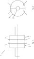
- a typical refiner 1 comprising refiner elements in the form of a coaxially arranged stator/rotor disc pair 2, 3 according to prior art is schematically illustrated in Figure 1 .
- At least one of the refiner elements/discs 2, 3 is provided with a refining surface comprising a plurality of refiner segments 4, as illustrated in Figure 2 .
- Each refiner segment 4 has a radially inner edge 41 facing the center of the refiner element and a radially outer/peripheral edge 42 facing the periphery of the refiner element, when the refiner segment 4 is arranged on the refiner element 2; 3.
- the stator/rotor disc pair 2, 3 can comprise e.g. one stator 2 and one rotor 3, or two rotors. In case of the rotor/rotor arrangement the two rotors are configured with opposing rotational directions.
- the main emphasis is on disc refiners, but the disclosure can be equally implemented in other refiner geometries as well.
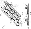
- Fig. 3a is a schematic illustration of a part of a refiner segment 4 arrangeable on a refiner element according to prior art, where the refiner segment 4 is provided with bars 10 and intermediate grooves 11 extending in a substantially radial direction, and dams 12 extending between the bars 10 and protruding above the surface of the grooves 11.
- the figure shows the steam flow 8 and the flow of fibrous material 7 on the refiner segment 4, when the refiner segment 4 is travelling in a first circumferential direction 20 corresponding to an intended travelling direction of the refiner segment 4, which corresponds to an intended rotational direction of the refiner element when the refiner segment 4 is arranged on the refiner element.
- Fig. 3a illustrates an example where the first circumferential direction 20 of the refiner segment 4 corresponds to a counterclockwise rotational direction of the refiner element.
- the material 7 flows in a direction towards the periphery of the refiner segment 4.
- the bars 10 and dams 12 typically form closed-off "boxes” or “cages”, as illustrated by the dashed box B, which traps the steam 8 and forces it upwards out of the grooves and out into the refining gap.
- Fig. 3b is a cross-section of the refiner segment 4 along the line A-A of Fig. 3a , illustrating the pitch build-up 9 of the material 7 in the area behind the dam 12, from a different view.
- Fig. 4a is a schematic illustration of a part of a refiner segment 4 arrangeable on a refiner element according to an embodiment of the present disclosure, where the refiner segment 4 is provided with bars 10 and intermediate grooves 11 extending in a substantially radial direction, and dams 12 extending between the bars 10 and protruding above the surface of the grooves 11.
- steam channels 13 are arranged through the bars 10 to provide a passage for the back-streaming steam 8.
- FIG. 4a illustrates an example where the first circumferential direction 20 of the refiner segment 4 corresponds to a counterclockwise rotational direction of the refiner element.
- the material 7 flows towards the periphery of the refiner segment 4, similarly as in Fig.
- Fig. 4b is a cross-section of the refiner segment 4 along the line A-A of Fig. 4a , illustrating how the steam flow 8 in the area behind the dam 12 prevents pitch build-up of the material 7 in the area behind the dam 12. The pressure from the flowing steam 8 helps to "flush away" the material 7 from this zone.
- each channel 13 is arranged through a bar 10 adjacent to the intersection between a dam 12 and a bar 10, peripherally of a respective dam 12 with respect to the inner edge of the refiner segment 4, i.e. radially outside of the dam 12.
- the channels 13 are arranged at a trailing end of the dams 12 with respect to a first circumferential direction 20 corresponding to an intended travelling direction of the refiner segment 4, where the intended travelling direction of the refiner segment 4 corresponds to an intended rotational direction of the refiner element, in order to guide the back-streaming steam 8 through a channel 13 into an adjacent groove 11.
- dams 12 in this embodiment are inclined such that the trailing end of a dam 12 is arranged closer to the inner edge of the refiner segment 4 than the leading end of the dam 12, so that they are "pointing" obliquely inwards on the refiner segment 4, in order to guide the back-streaming steam 8 along the peripheral edges/walls of the dams 12 towards the channels 13.
- the channels 13 should also be inclined so that they are pointing obliquely inwards on the refiner segment 4 in this embodiment, i.e. the trailing end of a channel 13 is arranged closer to the inner edge of the refiner segment 4 than a leading end of the channel 13.
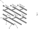
- Fig. 5 is a schematic illustration of a part of a refiner segment 4 showing different positions of the channel 13 according to an embodiment of the present disclosure.
- the distance L between a peripheral wall/edge of a dam 12 and the inlet opening of a channel 13 does not exceed 10 mm. If the distance L is too large, the steam will have trouble finding its way through the channel and into the adjacent groove, as shown by experiment and simulation. The two channels shown at the bottom right in Fig. 5 do not fulfil this condition.
- Figs. 6a-b are schematic illustrations of a part of a refiner segment showing different shapes to the channels 13 according to embodiments of the present disclosure.
- An outlet opening (O) for the steam is located at the trailing end of the channel (13) and an inlet opening (I) for the steam is located at the leading end of the channel (13).
- the inlet opening I of the channel 13 is smaller than the outlet opening O, as illustrated in Fig. 6b . If the outlet opening O is smaller than the inlet opening I, as illustrated in Fig. 6a , there is a risk that the steam flow through the channel 13 will be restricted by the narrowing of the channel 13.
- Figs. 7a-b are schematic illustrations of a part of a refiner segment showing different depths of the channel 13 according to embodiments of the present disclosure.
- the depth d of the channels 13 is larger than half the depth D of the groove, i.e. d>D/2, where the depths d, D are measured from a top surface of the bars 10 to a bottom surface of the channel 13 and the groove 11, respectively.
- the two leftmost channels shown in Fig. 7a do not fulfil this condition.
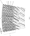
- Fig. 8 is a schematic illustration of steam flow in a part of a refiner segment 4 comprising at least one refining zone 6 according to an embodiment of the present disclosure.
- the channels 13 in this embodiment are provided over the entire surface of the refining zone 6 of the refiner segment 4, thereby creating/forming a free passage through the entire refining zone 6 for the steam 8 flowing through the channels and grooves towards the inner edge of the refiner segment and the center of the refiner element/disc. This will allow steam to be evacuated from the refining zone 6 with minimum conflict with the flow of wood/fibrous material.
- channels 13 are provided adjacent to all the dams 12 on the refiner segment 4.
- All embodiments of the present disclosure can be fitted to a refiner arrangement well known in the art, for example refiners with a rotor-stator arrangement as well as refiners with two rotors instead of a rotor-stator arrangement, i.e. two rotors that can be rotated independently.
- a refiner arrangement well known in the art, for example refiners with a rotor-stator arrangement as well as refiners with two rotors instead of a rotor-stator arrangement, i.e. two rotors that can be rotated independently.
- the main emphasis is on disc refiners, but the disclosure can be equally implemented in other refiner geometries as well.
Landscapes
- Engineering & Computer Science (AREA)
- Life Sciences & Earth Sciences (AREA)
- Wood Science & Technology (AREA)
- Mechanical Engineering (AREA)
- Food Science & Technology (AREA)
- Paper (AREA)
Abstract
Description
- The present invention generally relates to refining of fibrous material in a fiber refiner, and more particularly to feed variations during the refining process.
- Refiners used for refining fibrous material, such as wood chips, into pulp typically comprise one or more refiner elements positioned oppositely and rotating relative to each other. One or both of the refiner elements can be rotatable. A fixed i.e. stationary refiner element is called the stator and the rotating or rotatable refiner element is called the rotor. In disc refiners, the refiner elements are disc-like and in cone refiners the refiner elements are conical. In addition to disc refiners and cone refiners, there are also so-called disc-cone refiners where the material to be defibrated is first refined by disc-like refiner elements and then further refined between conical refiner elements. Furthermore, there are also cylindrical refiners where both the stator and the rotor of the refiner are cylindrical refiner elements.
- The refiner elements are positioned such that a refining space/gap is formed between the inner surfaces, i.e. the surfaces opposing one another, of the refiner segments. In disc refiners, which represent the most common refiner type, the material to be refined is usually fed through an opening in the middle of one of the refiner discs, usually the stator, to a central space between the discs. The material is then forced by the centrifugal force towards the circumference of the discs to emerge in the refining space/gap, where the refining/grinding of the fibrous material is carried out. The refined material is discharged from the refining space/gap, from the outer periphery of the refining surfaces of the refiner discs, to be fed onwards in the pulp manufacturing process.
- The inner (refining) surfaces of the refiner elements are typically provided with one or more refiner segments, which are formed with a pattern of bars and intermediate grooves of different sizes and orientations, for improving the grinding action on the fibers. The refiner segments are typically positioned adjacently in such a way that each refiner segment forms part of a continuous refining surface. The pattern of bars and grooves may be divided into different zones located outside each other, e.g. a radially inner inlet zone where the fibrous material is fed into the refiner, and a radially outer refining zone where the refining of the material takes place. In the inlet zone there are usually fewer bars and grooves, and the pattern is coarser than in the refining zone. Normally, the bars and grooves of the refiner segments extend substantially radially with respect to the rotational center of the refiner elements.
- When the fibrous material is refined in the refining space/gap between the refiner elements, some of the moisture in the material is turned into steam. The steam flow is usually very irregular, but some steam will flow towards the circumference of the refiner elements along with the material, and some of the steam will also flow "backwards" towards the center of the refiner elements. The steam flow will depend - among other things - on how the refiner segments are designed. The back-streaming steam will mainly flow in the grooves formed between the bars of the refiner segments towards the center of the refiner elements.
- Usually, flow restrictions or dams are inserted in the grooves in the refiner segments in order to prevent unprocessed material to pass out through the refining gap. The dams guide the material to the space between opposite refiner bars, and thereby refining of the material can be promoted. However, the dams constitute an obstacle to the steam developed in the refining gap during the refining process. The steam is also forced upwards out of the grooves by the dams and disturbs the material flow through the refining gap. This in turn leads to blockage on the refining surface, which may affect the stability of the refining gap, rendering the material flow through the gap nonuniform. Variations in feed within the refining gap causes a decrease in the production capacity of the refiner, non-uniformity of the quality of the refined material and an increase in the energy consumed for the refining. Therefore, there is a need for improving the design of the refiner segments in order to overcome the above mentioned disadvantages.
- It is an object to provide a refiner disc which reduces the feed variations during the refining process.
- This and other objects are met by embodiments of the proposed technology.
- According to a first aspect, there is provided a refiner segment for a refiner intended for refining fibrous material, where the refiner segment has a refining surface and is arrangeable to form a part of a refining surface of a refiner element in the refiner. The refiner segment has a radially inner edge and a radially outer edge and is provided with a pattern of bars and intermediate grooves extending along the refiner segment in a substantially radial direction with respect to the inner edge of the refiner segment, and dams extending between the bars and protruding above the surface of the grooves. The bars are provided with steam channels arranged through the bars, where each channel is located adjacent to an intersection between a bar and a dam, radially outside of a respective dam with respect to the inner edge of the refiner segment, and at a trailing end of the respective dam with respect to a first circumferential direction corresponding to an intended travelling direction of the refiner segment, where the steam channels are configured to allow steam flowing towards the inner edge of the refiner segment to pass through the steam channels in a direction having a component directed opposite to the first circumferential direction.
- According to a second aspect, there is provided a refiner for refining fibrous material, comprising at least one refiner segment according to the above.
- By introducing channels in the bars near the dams, thereby creating a passage for steam flowing towards the center of the refiner without forcing the steam into the refining gap, at least the following advantages can be achieved:
- Reducing feed conflicts in the refining gap which in turn leads to less feed disturbance, less vibrations, less micro-pulsation etc.
- Preventing the area just after the dams from becoming a "dead zone" with lower steam pressure and less movement of the material, which means that pitch build-up can be avoided.
- Other advantages will be appreciated when reading the detailed description.
- The invention, together with further objects and advantages thereof, may best be understood by making reference to the following description taken together with the accompanying drawings, in which:
-
Fig. 1 is a schematic illustration of a typical refiner comprising a coaxially arranged stator/rotor disc pair according to prior art technology. -
Fig. 2 is a schematic illustration of a refining surface comprising a plurality of refiner segments according to prior art technology. -
Fig. 3a is a schematic illustration of a part of a refiner segment according to prior art technology. -
Fig. 3b is a cross-section of the refiner segment ofFig. 3a . -
Fig. 4a is a schematic illustration of a part of a refiner segment according to an embodiment of the present disclosure. -
Fig. 4b is a cross-section of the refiner segment ofFig. 4a . -
Fig. 5 is a schematic illustration of a part of a refiner segment according to an embodiment of the present disclosure. -
Figs. 6a-b are schematic illustrations of a part of a refiner segment according to embodiments of the present disclosure. -
Figs. 7a-b are schematic illustrations of a part of a refiner segment according to embodiments of the present disclosure. -
Fig. 8 is a schematic illustration of steam flow in a part of a refiner segment according to an embodiment of the present disclosure. - Throughout the drawings, the same reference designations are used for similar or corresponding elements.
- For further illustration of the prior art, a
typical refiner 1 comprising refiner elements in the form of a coaxially arranged stator/rotor disc pair Figure 1 . At least one of the refiner elements/discs refiner segments 4, as illustrated inFigure 2 . Eachrefiner segment 4 has a radiallyinner edge 41 facing the center of the refiner element and a radially outer/peripheral edge 42 facing the periphery of the refiner element, when therefiner segment 4 is arranged on therefiner element 2; 3. The stator/rotor disc pair stator 2 and onerotor 3, or two rotors. In case of the rotor/rotor arrangement the two rotors are configured with opposing rotational directions. In the current disclosure the main emphasis is on disc refiners, but the disclosure can be equally implemented in other refiner geometries as well. - As described in the background section there is continued need in the art to further reduce the feed variations during the refining process.
Fig. 3a is a schematic illustration of a part of arefiner segment 4 arrangeable on a refiner element according to prior art, where therefiner segment 4 is provided withbars 10 andintermediate grooves 11 extending in a substantially radial direction, anddams 12 extending between thebars 10 and protruding above the surface of thegrooves 11. The figure shows thesteam flow 8 and the flow offibrous material 7 on therefiner segment 4, when therefiner segment 4 is travelling in a firstcircumferential direction 20 corresponding to an intended travelling direction of therefiner segment 4, which corresponds to an intended rotational direction of the refiner element when therefiner segment 4 is arranged on the refiner element.Fig. 3a illustrates an example where the firstcircumferential direction 20 of therefiner segment 4 corresponds to a counterclockwise rotational direction of the refiner element. Thematerial 7 flows in a direction towards the periphery of therefiner segment 4. In conventional refiner segment designs thebars 10 anddams 12 typically form closed-off "boxes" or "cages", as illustrated by the dashed box B, which traps thesteam 8 and forces it upwards out of the grooves and out into the refining gap. At least the following problems are associated with this design: -
Steam 8 that is trying to go backwards (or forwards) is "caged in" and forced to find its way out into the refining gap. This causes feed conflicts between thesteam 8 and thefibrous material 7 in the refining gap, which leads to feed disturbance, vibrations, micro-pulsation etc. - The area just after the
dams 12 becomes a "dead zone" with lower steam pressure and much less movement of thematerial 7, which causes pitch build-up 9 of the material in this zone. Once this pitch build-up starts, it will escalate. -
Fig. 3b is a cross-section of therefiner segment 4 along the line A-A ofFig. 3a , illustrating the pitch build-up 9 of thematerial 7 in the area behind thedam 12, from a different view. - The present embodiments solve the above-mentioned problems by opening up channels in the bars near the dams to release the steam from the "cages" without forcing the steam into the refining gap.
Fig. 4a is a schematic illustration of a part of arefiner segment 4 arrangeable on a refiner element according to an embodiment of the present disclosure, where therefiner segment 4 is provided withbars 10 andintermediate grooves 11 extending in a substantially radial direction, anddams 12 extending between thebars 10 and protruding above the surface of thegrooves 11. In thisembodiment steam channels 13 are arranged through thebars 10 to provide a passage for the back-streamingsteam 8. The figure shows thesteam flow 8 and the flow offibrous material 7 on therefiner segment 4, when therefiner segment 4 is travelling in a firstcircumferential direction 20 corresponding to an intended travelling direction of therefiner segment 4, which correspond to an intended rotational direction of the refiner element when therefiner segment 4 is arranged on the refiner element.Fig. 4a illustrates an example where the firstcircumferential direction 20 of therefiner segment 4 corresponds to a counterclockwise rotational direction of the refiner element. Here thematerial 7 flows towards the periphery of therefiner segment 4, similarly as inFig. 3b , but the back-streamingsteam 8 travelling towards the inner edge of therefiner segment 4 flows along thedams 12 and passes through thechannels 13 in thebars 10 in a direction having a component directed opposite to the firstcircumferential direction 20, into anadjacent groove 11, and then through anext channel 13, and so on towards the inner edge of the refiner segment. At least the following advantages are achieved with this design: - Steam is released from the boxes or cages without forcing the steam to escape into the refining gap. This reduces feed conflicts in the refining gap which in turn leads to less feed disturbance, less vibrations, less micro-pulsation etc.
- The position of the channels creates steam flow and movement in the area just after the dams, which prevents this area from becoming a "dead zone" with lower steam pressure and less movement of the material, which means that pitch build-up can be avoided.
- This is achieved without interfering with the flow of wood/fibrous material.
-
Fig. 4b is a cross-section of therefiner segment 4 along the line A-A ofFig. 4a , illustrating how thesteam flow 8 in the area behind thedam 12 prevents pitch build-up of thematerial 7 in the area behind thedam 12. The pressure from the flowingsteam 8 helps to "flush away" thematerial 7 from this zone. - In the embodiment illustrated in
Fig. 4a , eachchannel 13 is arranged through abar 10 adjacent to the intersection between adam 12 and abar 10, peripherally of arespective dam 12 with respect to the inner edge of therefiner segment 4, i.e. radially outside of thedam 12. Thechannels 13 are arranged at a trailing end of thedams 12 with respect to a firstcircumferential direction 20 corresponding to an intended travelling direction of therefiner segment 4, where the intended travelling direction of therefiner segment 4 corresponds to an intended rotational direction of the refiner element, in order to guide the back-streamingsteam 8 through achannel 13 into anadjacent groove 11. Furthermore, thedams 12 in this embodiment are inclined such that the trailing end of adam 12 is arranged closer to the inner edge of therefiner segment 4 than the leading end of thedam 12, so that they are "pointing" obliquely inwards on therefiner segment 4, in order to guide the back-streamingsteam 8 along the peripheral edges/walls of thedams 12 towards thechannels 13. Thechannels 13 should also be inclined so that they are pointing obliquely inwards on therefiner segment 4 in this embodiment, i.e. the trailing end of achannel 13 is arranged closer to the inner edge of therefiner segment 4 than a leading end of thechannel 13. -
Fig. 5 is a schematic illustration of a part of arefiner segment 4 showing different positions of thechannel 13 according to an embodiment of the present disclosure. In a particular embodiment of a refiner segment for refining fibrous material according to the present disclosure the distance L between a peripheral wall/edge of adam 12 and the inlet opening of achannel 13 does not exceed 10 mm. If the distance L is too large, the steam will have trouble finding its way through the channel and into the adjacent groove, as shown by experiment and simulation. The two channels shown at the bottom right inFig. 5 do not fulfil this condition. - Similarly,
Figs. 6a-b are schematic illustrations of a part of a refiner segment showing different shapes to thechannels 13 according to embodiments of the present disclosure. An outlet opening (O) for the steam is located at the trailing end of the channel (13) and an inlet opening (I) for the steam is located at the leading end of the channel (13). In a particular embodiment of a refiner segment for refining fibrous material the inlet opening I of thechannel 13 is smaller than the outlet opening O, as illustrated inFig. 6b . If the outlet opening O is smaller than the inlet opening I, as illustrated inFig. 6a , there is a risk that the steam flow through thechannel 13 will be restricted by the narrowing of thechannel 13. -
Figs. 7a-b are schematic illustrations of a part of a refiner segment showing different depths of thechannel 13 according to embodiments of the present disclosure. In a particular embodiment of a refiner segment for refining fibrous material the depth d of thechannels 13 is larger than half the depth D of the groove, i.e. d>D/2, where the depths d, D are measured from a top surface of thebars 10 to a bottom surface of thechannel 13 and thegroove 11, respectively. The two leftmost channels shown inFig. 7a do not fulfil this condition. -
Fig. 8 is a schematic illustration of steam flow in a part of arefiner segment 4 comprising at least onerefining zone 6 according to an embodiment of the present disclosure. As illustrated inFig. 8 , thechannels 13 in this embodiment are provided over the entire surface of therefining zone 6 of therefiner segment 4, thereby creating/forming a free passage through theentire refining zone 6 for thesteam 8 flowing through the channels and grooves towards the inner edge of the refiner segment and the center of the refiner element/disc. This will allow steam to be evacuated from therefining zone 6 with minimum conflict with the flow of wood/fibrous material. In a particular embodiment,channels 13 are provided adjacent to all thedams 12 on therefiner segment 4. - All embodiments of the present disclosure can be fitted to a refiner arrangement well known in the art, for example refiners with a rotor-stator arrangement as well as refiners with two rotors instead of a rotor-stator arrangement, i.e. two rotors that can be rotated independently. In the current disclosure the main emphasis is on disc refiners, but the disclosure can be equally implemented in other refiner geometries as well.
- The embodiments described above are merely given as examples, and it should be understood that the proposed technology is not limited thereto. It will be understood by those skilled in the art that various modifications, combinations and changes may be made to the embodiments without departing from the present scope as defined by the appended claims. In particular, different part solutions in the different embodiments can be combined in other configurations, where technically possible.
Claims (8)
- A refiner segment (4) for a refiner (1) intended for refining fibrous material (7), the refiner segment (4) having a refining surface and being arrangeable to form a part of a refining surface of a refiner element (2; 3) in the refiner (1), the refiner segment (4) having a radially inner edge (41) and a radially outer edge (42) and being provided with a pattern of bars (10) and intermediate grooves (11) extending along the refiner segment (4) in a substantially radial direction with respect to the inner edge (41) of the refiner segment (4), and dams (12) extending between the bars (10) and protruding above the surface of the grooves (11), characterized in that
the bars (10) are provided with steam channels (13) arranged through the bars (10), each channel (13) being located adjacent to an intersection between a bar (10) and a dam (12), radially outside of a respective dam (12) with respect to the inner edge (41) of the refiner segment (4), and at a trailing end of the respective dam (12) with respect to a first circumferential direction (20) corresponding to an intended travelling direction of the refiner segment (4), the steam channels (13) being configured to allow steam (8) flowing towards the inner edge (41) of the refiner segment (4) to pass through the steam channels (13) in a direction having a component directed opposite to the first circumferential direction (20). - The refiner segment (4) according to claim 1, characterized in that the dams (12) are inclined such that the trailing end of a dam (12) is arranged closer to the inner edge (41) of the refiner segment (4) than a leading end of the dam (12), with respect to the first circumferential direction (20) of the refiner segment (4).
- The refiner segment (4) according to claim 1 or 2, characterized in that the channels (13) are inclined such that an outlet opening (O) of a channel (13) is arranged closer to the inner edge (41) of the refiner segment (4) than an inlet opening (I) of a channel (13), where the outlet opening (O) is located at a trailing end of the channel (13) and the inlet opening (I) is located at a leading end of the channel (13) with respect to the first circumferential direction (20) of the refiner segment (4).
- The refiner segment (4) according to claim 3, characterized in that the inlet openings (I) of the channels (13) are arranged at a distance (L) which smaller than or equal to 10 mm from a peripheral, with respect to the inner edge (41) of the refiner segment (4), wall of a dam (12).
- The refiner segment (4) according to claim 3 or 4, characterized in that the inlet openings (I) of the channels (13) are smaller than the outlet openings (O) of the channels (13).
- The refiner segment (4) according to any of the claims 1 to 5, characterized in that a depth (d) of each channel (13) is larger than a depth (D) of the grooves (11) divided by two, where the depths (d, D) are measured from a top surface of the bars (10) to a bottom surface of the channel (13) and the groove (11), respectively.
- The refiner segment (4) according to any of the claims 1 to 6, comprising at least one refining zone (6) where refining of the fibrous material (7) takes place, characterized in that channels (13) are provided over the entire refining zone (6), thereby forming a free passage through the entire refining zone (6) for steam (8) flowing towards the inner edge (41) of the refiner segment (4).
- A refiner (1) for refining fibrous material, characterized in that it comprises at least one refiner segment (4) according to any of the claims 1 to 7.
Applications Claiming Priority (1)
| Application Number | Priority Date | Filing Date | Title |
|---|---|---|---|
| SE1751058A SE540890C2 (en) | 2017-09-01 | 2017-09-01 | Refiner segment in a fiber refiner |
Publications (2)
| Publication Number | Publication Date |
|---|---|
| EP3450624A1 true EP3450624A1 (en) | 2019-03-06 |
| EP3450624B1 EP3450624B1 (en) | 2024-07-17 |
Family
ID=63405154
Family Applications (1)
| Application Number | Title | Priority Date | Filing Date |
|---|---|---|---|
| EP18446502.9A Active EP3450624B1 (en) | 2017-09-01 | 2018-08-24 | Refiner segment for a fiber refiner |
Country Status (4)
| Country | Link |
|---|---|
| US (1) | US10767309B2 (en) |
| EP (1) | EP3450624B1 (en) |
| CN (1) | CN109423911B (en) |
| SE (1) | SE540890C2 (en) |
Cited By (3)
| Publication number | Priority date | Publication date | Assignee | Title |
|---|---|---|---|---|
| EP4063561A1 (en) * | 2021-03-24 | 2022-09-28 | Valmet Ab | Refiner segment |
| WO2025237947A1 (en) | 2024-05-15 | 2025-11-20 | Voith Patent Gmbh | Milling surfaces for treating aqueous suspension |
| WO2025237944A1 (en) | 2024-05-15 | 2025-11-20 | Voith Patent Gmbh | Grinding surfaces for treating aqueous suspension |
Families Citing this family (10)
| Publication number | Priority date | Publication date | Assignee | Title |
|---|---|---|---|---|
| US11001968B2 (en) | 2018-01-02 | 2021-05-11 | International Paper Company | Apparatus and method for processing wood fibers |
| US10794003B2 (en) | 2018-01-02 | 2020-10-06 | International Paper Company | Apparatus and method for processing wood fibers |
| US11421382B2 (en) | 2018-01-02 | 2022-08-23 | International Paper Company | Apparatus and method for processing wood fibers |
| SE544375C2 (en) * | 2020-02-17 | 2022-04-26 | Valmet Oy | Blade for a refiner |
| US11555273B2 (en) * | 2021-04-16 | 2023-01-17 | Andritz Inc. | Flow-altering refiner segment |
| US20240392502A1 (en) * | 2021-09-20 | 2024-11-28 | Papyrus Australia Limited | Method and apparatus for producing a mouldable cellulosic fibrous material |
| SE2330254A1 (en) * | 2023-06-02 | 2024-12-03 | Valmet Oy | Blade, refiner comprising a blade, and method for manufacturing a blade |
| SE546383C2 (en) * | 2023-06-21 | 2024-10-22 | Valmet Oy | Blade for a refiner for refining lignocellulosic material, and refiner comprising at least one blade |
| WO2025040290A1 (en) | 2023-08-21 | 2025-02-27 | Valmet Ab | Method, system and program for producing a refiner segment out of a worn refiner segment, and a rebuilt refiner segment |
| SE548027C2 (en) * | 2024-01-15 | 2026-01-13 | Valmet Oy | Blade for a refiner for refining lignocellulosic material, and refiner comprising such a blade |
Citations (2)
| Publication number | Priority date | Publication date | Assignee | Title |
|---|---|---|---|---|
| US4953796A (en) * | 1987-02-25 | 1990-09-04 | Sunds Defibrator Aktiebolag | Refiner segment |
| US5373995A (en) * | 1993-08-25 | 1994-12-20 | Johansson; Ola M. | Vented refiner and venting process |
Family Cites Families (8)
| Publication number | Priority date | Publication date | Assignee | Title |
|---|---|---|---|---|
| SE418309B (en) * | 1977-09-30 | 1981-05-18 | Sca Development Ab | SET AND DEVICE FOR REFINING FIBER MATERIAL IN A DISC REFINER |
| SE508286C2 (en) | 1997-01-31 | 1998-09-21 | Sunds Defibrator Ind Ab | Grinding elements for disc refiners with booms and intermediate tracks and channels for free passage of steam |
| US5988538A (en) * | 1998-07-28 | 1999-11-23 | J&L Fiber Services, Inc. | Refiner disc having steam exhaust channel |
| US6032888A (en) * | 1999-04-16 | 2000-03-07 | Durametal Corporation | Refiner plate with interspersed surface and subsurface dams |
| US6402071B1 (en) * | 1999-11-23 | 2002-06-11 | Durametal Corporation | Refiner plates with injector inlet |
| CN2558454Y (en) * | 2002-07-06 | 2003-07-02 | 岳阳纸业股份有限公司 | High concentration disc mill abrasive disc |
| US8028945B2 (en) | 2007-05-31 | 2011-10-04 | Andritz Inc. | Refiner plates having steam channels and method for extracting backflow steam from a disk refiner |
| US9604221B2 (en) * | 2012-11-09 | 2017-03-28 | Andrtiz Inc. | Stator refiner plate element having curved bars and serrated leading edges |
-
2017
- 2017-09-01 SE SE1751058A patent/SE540890C2/en unknown
-
2018
- 2018-08-24 EP EP18446502.9A patent/EP3450624B1/en active Active
- 2018-08-31 US US16/119,025 patent/US10767309B2/en active Active
- 2018-09-03 CN CN201811018491.7A patent/CN109423911B/en active Active
Patent Citations (2)
| Publication number | Priority date | Publication date | Assignee | Title |
|---|---|---|---|---|
| US4953796A (en) * | 1987-02-25 | 1990-09-04 | Sunds Defibrator Aktiebolag | Refiner segment |
| US5373995A (en) * | 1993-08-25 | 1994-12-20 | Johansson; Ola M. | Vented refiner and venting process |
Cited By (3)
| Publication number | Priority date | Publication date | Assignee | Title |
|---|---|---|---|---|
| EP4063561A1 (en) * | 2021-03-24 | 2022-09-28 | Valmet Ab | Refiner segment |
| WO2025237947A1 (en) | 2024-05-15 | 2025-11-20 | Voith Patent Gmbh | Milling surfaces for treating aqueous suspension |
| WO2025237944A1 (en) | 2024-05-15 | 2025-11-20 | Voith Patent Gmbh | Grinding surfaces for treating aqueous suspension |
Also Published As
| Publication number | Publication date |
|---|---|
| EP3450624B1 (en) | 2024-07-17 |
| SE1751058A1 (en) | 2018-12-11 |
| US10767309B2 (en) | 2020-09-08 |
| SE540890C2 (en) | 2018-12-11 |
| US20190071821A1 (en) | 2019-03-07 |
| CN109423911A (en) | 2019-03-05 |
| CN109423911B (en) | 2022-02-11 |
Similar Documents
| Publication | Publication Date | Title |
|---|---|---|
| US10767309B2 (en) | Refiner segment in a fiber refiner | |
| US10927499B2 (en) | Refiner segment in a fiber refiner | |
| CN108855461B (en) | Blade segment for refiner | |
| EP1644119B1 (en) | Refiner | |
| US10378149B2 (en) | Refiner plate segment with pre-dam | |
| EP0348418B1 (en) | Refiner segment | |
| EP2414586B1 (en) | Refining surface for a refiner | |
| US10449545B2 (en) | Feeding center plate in a pulp or fiber refiner | |
| US10464068B2 (en) | Blade element for refiner | |
| US10441954B2 (en) | Single-disc refiner | |
| EP4414500B1 (en) | Refining segment | |
| US11512429B2 (en) | Steam evacuation in a pulp or fiber refiner | |
| EP2279041B1 (en) | A refining segment for pulp processing with a deflector arrangement | |
| WO1998033594A1 (en) | Refining element | |
| US10953405B2 (en) | Blade element | |
| CN115702273A (en) | Blade segments for refiners | |
| KR20230024290A (en) | Blade segments for refiners |
Legal Events
| Date | Code | Title | Description |
|---|---|---|---|
| PUAI | Public reference made under article 153(3) epc to a published international application that has entered the european phase |
Free format text: ORIGINAL CODE: 0009012 |
|
| STAA | Information on the status of an ep patent application or granted ep patent |
Free format text: STATUS: THE APPLICATION HAS BEEN PUBLISHED |
|
| AK | Designated contracting states |
Kind code of ref document: A1 Designated state(s): AL AT BE BG CH CY CZ DE DK EE ES FI FR GB GR HR HU IE IS IT LI LT LU LV MC MK MT NL NO PL PT RO RS SE SI SK SM TR |
|
| AX | Request for extension of the european patent |
Extension state: BA ME |
|
| STAA | Information on the status of an ep patent application or granted ep patent |
Free format text: STATUS: REQUEST FOR EXAMINATION WAS MADE |
|
| 17P | Request for examination filed |
Effective date: 20190906 |
|
| RBV | Designated contracting states (corrected) |
Designated state(s): AL AT BE BG CH CY CZ DE DK EE ES FI FR GB GR HR HU IE IS IT LI LT LU LV MC MK MT NL NO PL PT RO RS SE SI SK SM TR |
|
| STAA | Information on the status of an ep patent application or granted ep patent |
Free format text: STATUS: EXAMINATION IS IN PROGRESS |
|
| 17Q | First examination report despatched |
Effective date: 20220609 |
|
| P01 | Opt-out of the competence of the unified patent court (upc) registered |
Effective date: 20230607 |
|
| GRAP | Despatch of communication of intention to grant a patent |
Free format text: ORIGINAL CODE: EPIDOSNIGR1 |
|
| STAA | Information on the status of an ep patent application or granted ep patent |
Free format text: STATUS: GRANT OF PATENT IS INTENDED |
|
| INTG | Intention to grant announced |
Effective date: 20240423 |
|
| GRAS | Grant fee paid |
Free format text: ORIGINAL CODE: EPIDOSNIGR3 |
|
| GRAA | (expected) grant |
Free format text: ORIGINAL CODE: 0009210 |
|
| STAA | Information on the status of an ep patent application or granted ep patent |
Free format text: STATUS: THE PATENT HAS BEEN GRANTED |
|
| AK | Designated contracting states |
Kind code of ref document: B1 Designated state(s): AL AT BE BG CH CY CZ DE DK EE ES FI FR GB GR HR HU IE IS IT LI LT LU LV MC MK MT NL NO PL PT RO RS SE SI SK SM TR |
|
| REG | Reference to a national code |
Ref country code: CH Ref legal event code: EP |
|
| REG | Reference to a national code |
Ref country code: DE Ref legal event code: R096 Ref document number: 602018071821 Country of ref document: DE |
|
| REG | Reference to a national code |
Ref country code: IE Ref legal event code: FG4D |
|
| REG | Reference to a national code |
Ref country code: LT Ref legal event code: MG9D |
|
| REG | Reference to a national code |
Ref country code: AT Ref legal event code: UEP Ref document number: 1704233 Country of ref document: AT Kind code of ref document: T Effective date: 20240717 |
|
| REG | Reference to a national code |
Ref country code: NL Ref legal event code: MP Effective date: 20240717 |
|
| PG25 | Lapsed in a contracting state [announced via postgrant information from national office to epo] |
Ref country code: PT Free format text: LAPSE BECAUSE OF FAILURE TO SUBMIT A TRANSLATION OF THE DESCRIPTION OR TO PAY THE FEE WITHIN THE PRESCRIBED TIME-LIMIT Effective date: 20241118 |
|
| PG25 | Lapsed in a contracting state [announced via postgrant information from national office to epo] |
Ref country code: NL Free format text: LAPSE BECAUSE OF FAILURE TO SUBMIT A TRANSLATION OF THE DESCRIPTION OR TO PAY THE FEE WITHIN THE PRESCRIBED TIME-LIMIT Effective date: 20240717 |
|
| PG25 | Lapsed in a contracting state [announced via postgrant information from national office to epo] |
Ref country code: PT Free format text: LAPSE BECAUSE OF FAILURE TO SUBMIT A TRANSLATION OF THE DESCRIPTION OR TO PAY THE FEE WITHIN THE PRESCRIBED TIME-LIMIT Effective date: 20241118 Ref country code: NL Free format text: LAPSE BECAUSE OF FAILURE TO SUBMIT A TRANSLATION OF THE DESCRIPTION OR TO PAY THE FEE WITHIN THE PRESCRIBED TIME-LIMIT Effective date: 20240717 |
|
| PG25 | Lapsed in a contracting state [announced via postgrant information from national office to epo] |
Ref country code: NO Free format text: LAPSE BECAUSE OF FAILURE TO SUBMIT A TRANSLATION OF THE DESCRIPTION OR TO PAY THE FEE WITHIN THE PRESCRIBED TIME-LIMIT Effective date: 20241017 |
|
| PG25 | Lapsed in a contracting state [announced via postgrant information from national office to epo] |
Ref country code: PL Free format text: LAPSE BECAUSE OF FAILURE TO SUBMIT A TRANSLATION OF THE DESCRIPTION OR TO PAY THE FEE WITHIN THE PRESCRIBED TIME-LIMIT Effective date: 20240717 Ref country code: FI Free format text: LAPSE BECAUSE OF FAILURE TO SUBMIT A TRANSLATION OF THE DESCRIPTION OR TO PAY THE FEE WITHIN THE PRESCRIBED TIME-LIMIT Effective date: 20240717 Ref country code: GR Free format text: LAPSE BECAUSE OF FAILURE TO SUBMIT A TRANSLATION OF THE DESCRIPTION OR TO PAY THE FEE WITHIN THE PRESCRIBED TIME-LIMIT Effective date: 20241018 |
|
| PG25 | Lapsed in a contracting state [announced via postgrant information from national office to epo] |
Ref country code: BG Free format text: LAPSE BECAUSE OF FAILURE TO SUBMIT A TRANSLATION OF THE DESCRIPTION OR TO PAY THE FEE WITHIN THE PRESCRIBED TIME-LIMIT Effective date: 20240717 |
|
| PG25 | Lapsed in a contracting state [announced via postgrant information from national office to epo] |
Ref country code: LV Free format text: LAPSE BECAUSE OF FAILURE TO SUBMIT A TRANSLATION OF THE DESCRIPTION OR TO PAY THE FEE WITHIN THE PRESCRIBED TIME-LIMIT Effective date: 20240717 |
|
| PG25 | Lapsed in a contracting state [announced via postgrant information from national office to epo] |
Ref country code: IS Free format text: LAPSE BECAUSE OF FAILURE TO SUBMIT A TRANSLATION OF THE DESCRIPTION OR TO PAY THE FEE WITHIN THE PRESCRIBED TIME-LIMIT Effective date: 20241117 |
|
| PG25 | Lapsed in a contracting state [announced via postgrant information from national office to epo] |
Ref country code: HR Free format text: LAPSE BECAUSE OF FAILURE TO SUBMIT A TRANSLATION OF THE DESCRIPTION OR TO PAY THE FEE WITHIN THE PRESCRIBED TIME-LIMIT Effective date: 20240717 |
|
| PG25 | Lapsed in a contracting state [announced via postgrant information from national office to epo] |
Ref country code: ES Free format text: LAPSE BECAUSE OF FAILURE TO SUBMIT A TRANSLATION OF THE DESCRIPTION OR TO PAY THE FEE WITHIN THE PRESCRIBED TIME-LIMIT Effective date: 20240717 Ref country code: RS Free format text: LAPSE BECAUSE OF FAILURE TO SUBMIT A TRANSLATION OF THE DESCRIPTION OR TO PAY THE FEE WITHIN THE PRESCRIBED TIME-LIMIT Effective date: 20241017 |
|
| PG25 | Lapsed in a contracting state [announced via postgrant information from national office to epo] |
Ref country code: RS Free format text: LAPSE BECAUSE OF FAILURE TO SUBMIT A TRANSLATION OF THE DESCRIPTION OR TO PAY THE FEE WITHIN THE PRESCRIBED TIME-LIMIT Effective date: 20241017 Ref country code: PL Free format text: LAPSE BECAUSE OF FAILURE TO SUBMIT A TRANSLATION OF THE DESCRIPTION OR TO PAY THE FEE WITHIN THE PRESCRIBED TIME-LIMIT Effective date: 20240717 Ref country code: NO Free format text: LAPSE BECAUSE OF FAILURE TO SUBMIT A TRANSLATION OF THE DESCRIPTION OR TO PAY THE FEE WITHIN THE PRESCRIBED TIME-LIMIT Effective date: 20241017 Ref country code: LV Free format text: LAPSE BECAUSE OF FAILURE TO SUBMIT A TRANSLATION OF THE DESCRIPTION OR TO PAY THE FEE WITHIN THE PRESCRIBED TIME-LIMIT Effective date: 20240717 Ref country code: IS Free format text: LAPSE BECAUSE OF FAILURE TO SUBMIT A TRANSLATION OF THE DESCRIPTION OR TO PAY THE FEE WITHIN THE PRESCRIBED TIME-LIMIT Effective date: 20241117 Ref country code: HR Free format text: LAPSE BECAUSE OF FAILURE TO SUBMIT A TRANSLATION OF THE DESCRIPTION OR TO PAY THE FEE WITHIN THE PRESCRIBED TIME-LIMIT Effective date: 20240717 Ref country code: GR Free format text: LAPSE BECAUSE OF FAILURE TO SUBMIT A TRANSLATION OF THE DESCRIPTION OR TO PAY THE FEE WITHIN THE PRESCRIBED TIME-LIMIT Effective date: 20241018 Ref country code: FI Free format text: LAPSE BECAUSE OF FAILURE TO SUBMIT A TRANSLATION OF THE DESCRIPTION OR TO PAY THE FEE WITHIN THE PRESCRIBED TIME-LIMIT Effective date: 20240717 Ref country code: ES Free format text: LAPSE BECAUSE OF FAILURE TO SUBMIT A TRANSLATION OF THE DESCRIPTION OR TO PAY THE FEE WITHIN THE PRESCRIBED TIME-LIMIT Effective date: 20240717 Ref country code: BG Free format text: LAPSE BECAUSE OF FAILURE TO SUBMIT A TRANSLATION OF THE DESCRIPTION OR TO PAY THE FEE WITHIN THE PRESCRIBED TIME-LIMIT Effective date: 20240717 |
|
| REG | Reference to a national code |
Ref country code: CH Ref legal event code: PL |
|
| PG25 | Lapsed in a contracting state [announced via postgrant information from national office to epo] |
Ref country code: DK Free format text: LAPSE BECAUSE OF FAILURE TO SUBMIT A TRANSLATION OF THE DESCRIPTION OR TO PAY THE FEE WITHIN THE PRESCRIBED TIME-LIMIT Effective date: 20240717 Ref country code: SM Free format text: LAPSE BECAUSE OF FAILURE TO SUBMIT A TRANSLATION OF THE DESCRIPTION OR TO PAY THE FEE WITHIN THE PRESCRIBED TIME-LIMIT Effective date: 20240717 Ref country code: RO Free format text: LAPSE BECAUSE OF FAILURE TO SUBMIT A TRANSLATION OF THE DESCRIPTION OR TO PAY THE FEE WITHIN THE PRESCRIBED TIME-LIMIT Effective date: 20240717 |
|
| PG25 | Lapsed in a contracting state [announced via postgrant information from national office to epo] |
Ref country code: LU Free format text: LAPSE BECAUSE OF NON-PAYMENT OF DUE FEES Effective date: 20240824 |
|
| REG | Reference to a national code |
Ref country code: DE Ref legal event code: R097 Ref document number: 602018071821 Country of ref document: DE |
|
| PG25 | Lapsed in a contracting state [announced via postgrant information from national office to epo] |
Ref country code: MC Free format text: LAPSE BECAUSE OF FAILURE TO SUBMIT A TRANSLATION OF THE DESCRIPTION OR TO PAY THE FEE WITHIN THE PRESCRIBED TIME-LIMIT Effective date: 20240717 Ref country code: CH Free format text: LAPSE BECAUSE OF NON-PAYMENT OF DUE FEES Effective date: 20240831 Ref country code: EE Free format text: LAPSE BECAUSE OF FAILURE TO SUBMIT A TRANSLATION OF THE DESCRIPTION OR TO PAY THE FEE WITHIN THE PRESCRIBED TIME-LIMIT Effective date: 20240717 |
|
| PG25 | Lapsed in a contracting state [announced via postgrant information from national office to epo] |
Ref country code: CZ Free format text: LAPSE BECAUSE OF FAILURE TO SUBMIT A TRANSLATION OF THE DESCRIPTION OR TO PAY THE FEE WITHIN THE PRESCRIBED TIME-LIMIT Effective date: 20240717 |
|
| PG25 | Lapsed in a contracting state [announced via postgrant information from national office to epo] |
Ref country code: SK Free format text: LAPSE BECAUSE OF FAILURE TO SUBMIT A TRANSLATION OF THE DESCRIPTION OR TO PAY THE FEE WITHIN THE PRESCRIBED TIME-LIMIT Effective date: 20240717 |
|
| PLBE | No opposition filed within time limit |
Free format text: ORIGINAL CODE: 0009261 |
|
| STAA | Information on the status of an ep patent application or granted ep patent |
Free format text: STATUS: NO OPPOSITION FILED WITHIN TIME LIMIT |
|
| 26N | No opposition filed |
Effective date: 20250422 |
|
| GBPC | Gb: european patent ceased through non-payment of renewal fee |
Effective date: 20241017 |
|
| REG | Reference to a national code |
Ref country code: BE Ref legal event code: MM Effective date: 20240831 |
|
| PG25 | Lapsed in a contracting state [announced via postgrant information from national office to epo] |
Ref country code: GB Free format text: LAPSE BECAUSE OF NON-PAYMENT OF DUE FEES Effective date: 20241017 |
|
| PG25 | Lapsed in a contracting state [announced via postgrant information from national office to epo] |
Ref country code: BE Free format text: LAPSE BECAUSE OF NON-PAYMENT OF DUE FEES Effective date: 20240831 |
|
| PG25 | Lapsed in a contracting state [announced via postgrant information from national office to epo] |
Ref country code: FR Free format text: LAPSE BECAUSE OF NON-PAYMENT OF DUE FEES Effective date: 20240917 |
|
| PG25 | Lapsed in a contracting state [announced via postgrant information from national office to epo] |
Ref country code: IE Free format text: LAPSE BECAUSE OF NON-PAYMENT OF DUE FEES Effective date: 20240824 |
|
| PG25 | Lapsed in a contracting state [announced via postgrant information from national office to epo] |
Ref country code: SE Free format text: LAPSE BECAUSE OF FAILURE TO SUBMIT A TRANSLATION OF THE DESCRIPTION OR TO PAY THE FEE WITHIN THE PRESCRIBED TIME-LIMIT Effective date: 20240717 |
|
| PGFP | Annual fee paid to national office [announced via postgrant information from national office to epo] |
Ref country code: DE Payment date: 20250819 Year of fee payment: 8 |
|
| PGFP | Annual fee paid to national office [announced via postgrant information from national office to epo] |
Ref country code: AT Payment date: 20250819 Year of fee payment: 8 |
|
| PG25 | Lapsed in a contracting state [announced via postgrant information from national office to epo] |
Ref country code: CY Free format text: LAPSE BECAUSE OF FAILURE TO SUBMIT A TRANSLATION OF THE DESCRIPTION OR TO PAY THE FEE WITHIN THE PRESCRIBED TIME-LIMIT; INVALID AB INITIO Effective date: 20180824 Ref country code: IT Free format text: LAPSE BECAUSE OF FAILURE TO SUBMIT A TRANSLATION OF THE DESCRIPTION OR TO PAY THE FEE WITHIN THE PRESCRIBED TIME-LIMIT Effective date: 20240717 |
|
| PG25 | Lapsed in a contracting state [announced via postgrant information from national office to epo] |
Ref country code: HU Free format text: LAPSE BECAUSE OF FAILURE TO SUBMIT A TRANSLATION OF THE DESCRIPTION OR TO PAY THE FEE WITHIN THE PRESCRIBED TIME-LIMIT; INVALID AB INITIO Effective date: 20180824 |