EP3450386B1 - Forklift - Google Patents
Forklift Download PDFInfo
- Publication number
- EP3450386B1 EP3450386B1 EP17189038.7A EP17189038A EP3450386B1 EP 3450386 B1 EP3450386 B1 EP 3450386B1 EP 17189038 A EP17189038 A EP 17189038A EP 3450386 B1 EP3450386 B1 EP 3450386B1
- Authority
- EP
- European Patent Office
- Prior art keywords
- seat
- forklift
- cabin
- forklift according
- safety bracket
- Prior art date
- Legal status (The legal status is an assumption and is not a legal conclusion. Google has not performed a legal analysis and makes no representation as to the accuracy of the status listed.)
- Active
Links
Images




Classifications
-
- B—PERFORMING OPERATIONS; TRANSPORTING
- B66—HOISTING; LIFTING; HAULING
- B66F—HOISTING, LIFTING, HAULING OR PUSHING, NOT OTHERWISE PROVIDED FOR, e.g. DEVICES WHICH APPLY A LIFTING OR PUSHING FORCE DIRECTLY TO THE SURFACE OF A LOAD
- B66F9/00—Devices for lifting or lowering bulky or heavy goods for loading or unloading purposes
- B66F9/06—Devices for lifting or lowering bulky or heavy goods for loading or unloading purposes movable, with their loads, on wheels or the like, e.g. fork-lift trucks
- B66F9/075—Constructional features or details
- B66F9/07545—Overhead guards
-
- B—PERFORMING OPERATIONS; TRANSPORTING
- B60—VEHICLES IN GENERAL
- B60N—SEATS SPECIALLY ADAPTED FOR VEHICLES; VEHICLE PASSENGER ACCOMMODATION NOT OTHERWISE PROVIDED FOR
- B60N2/00—Seats specially adapted for vehicles; Arrangement or mounting of seats in vehicles
- B60N2/02—Seats specially adapted for vehicles; Arrangement or mounting of seats in vehicles the seat or part thereof being movable, e.g. adjustable
- B60N2/04—Seats specially adapted for vehicles; Arrangement or mounting of seats in vehicles the seat or part thereof being movable, e.g. adjustable the whole seat being movable
- B60N2/14—Seats specially adapted for vehicles; Arrangement or mounting of seats in vehicles the seat or part thereof being movable, e.g. adjustable the whole seat being movable rotatable, e.g. to permit easy access
-
- B—PERFORMING OPERATIONS; TRANSPORTING
- B60—VEHICLES IN GENERAL
- B60N—SEATS SPECIALLY ADAPTED FOR VEHICLES; VEHICLE PASSENGER ACCOMMODATION NOT OTHERWISE PROVIDED FOR
- B60N2/00—Seats specially adapted for vehicles; Arrangement or mounting of seats in vehicles
- B60N2/24—Seats specially adapted for vehicles; Arrangement or mounting of seats in vehicles for particular purposes or particular vehicles
-
- B—PERFORMING OPERATIONS; TRANSPORTING
- B60—VEHICLES IN GENERAL
- B60N—SEATS SPECIALLY ADAPTED FOR VEHICLES; VEHICLE PASSENGER ACCOMMODATION NOT OTHERWISE PROVIDED FOR
- B60N2/00—Seats specially adapted for vehicles; Arrangement or mounting of seats in vehicles
- B60N2/24—Seats specially adapted for vehicles; Arrangement or mounting of seats in vehicles for particular purposes or particular vehicles
- B60N2/26—Seats specially adapted for vehicles; Arrangement or mounting of seats in vehicles for particular purposes or particular vehicles for children
- B60N2/28—Seats readily mountable on, and dismountable from, existing seats or other parts of the vehicle
- B60N2/2872—Seats readily mountable on, and dismountable from, existing seats or other parts of the vehicle provided with side rests
-
- B—PERFORMING OPERATIONS; TRANSPORTING
- B60—VEHICLES IN GENERAL
- B60N—SEATS SPECIALLY ADAPTED FOR VEHICLES; VEHICLE PASSENGER ACCOMMODATION NOT OTHERWISE PROVIDED FOR
- B60N2/00—Seats specially adapted for vehicles; Arrangement or mounting of seats in vehicles
- B60N2/75—Arm-rests
- B60N2/753—Arm-rests movable to an inoperative position
-
- B—PERFORMING OPERATIONS; TRANSPORTING
- B60—VEHICLES IN GENERAL
- B60R—VEHICLES, VEHICLE FITTINGS, OR VEHICLE PARTS, NOT OTHERWISE PROVIDED FOR
- B60R21/00—Arrangements or fittings on vehicles for protecting or preventing injuries to occupants or pedestrians in case of accidents or other traffic risks
- B60R21/02—Occupant safety arrangements or fittings, e.g. crash pads
-
- B—PERFORMING OPERATIONS; TRANSPORTING
- B66—HOISTING; LIFTING; HAULING
- B66F—HOISTING, LIFTING, HAULING OR PUSHING, NOT OTHERWISE PROVIDED FOR, e.g. DEVICES WHICH APPLY A LIFTING OR PUSHING FORCE DIRECTLY TO THE SURFACE OF A LOAD
- B66F17/00—Safety devices, e.g. for limiting or indicating lifting force
- B66F17/003—Safety devices, e.g. for limiting or indicating lifting force for fork-lift trucks
-
- B—PERFORMING OPERATIONS; TRANSPORTING
- B66—HOISTING; LIFTING; HAULING
- B66F—HOISTING, LIFTING, HAULING OR PUSHING, NOT OTHERWISE PROVIDED FOR, e.g. DEVICES WHICH APPLY A LIFTING OR PUSHING FORCE DIRECTLY TO THE SURFACE OF A LOAD
- B66F9/00—Devices for lifting or lowering bulky or heavy goods for loading or unloading purposes
- B66F9/06—Devices for lifting or lowering bulky or heavy goods for loading or unloading purposes movable, with their loads, on wheels or the like, e.g. fork-lift trucks
- B66F9/075—Constructional features or details
- B66F9/0759—Details of operating station, e.g. seats, levers, operator platforms, cabin suspension
-
- B—PERFORMING OPERATIONS; TRANSPORTING
- B60—VEHICLES IN GENERAL
- B60N—SEATS SPECIALLY ADAPTED FOR VEHICLES; VEHICLE PASSENGER ACCOMMODATION NOT OTHERWISE PROVIDED FOR
- B60N2/00—Seats specially adapted for vehicles; Arrangement or mounting of seats in vehicles
- B60N2/24—Seats specially adapted for vehicles; Arrangement or mounting of seats in vehicles for particular purposes or particular vehicles
- B60N2/38—Seats specially adapted for vehicles; Arrangement or mounting of seats in vehicles for particular purposes or particular vehicles specially constructed for use on tractors or like off-road vehicles
-
- B—PERFORMING OPERATIONS; TRANSPORTING
- B60—VEHICLES IN GENERAL
- B60N—SEATS SPECIALLY ADAPTED FOR VEHICLES; VEHICLE PASSENGER ACCOMMODATION NOT OTHERWISE PROVIDED FOR
- B60N2/00—Seats specially adapted for vehicles; Arrangement or mounting of seats in vehicles
- B60N2/24—Seats specially adapted for vehicles; Arrangement or mounting of seats in vehicles for particular purposes or particular vehicles
- B60N2/42—Seats specially adapted for vehicles; Arrangement or mounting of seats in vehicles for particular purposes or particular vehicles the seat constructed to protect the occupant from the effect of abnormal g-forces, e.g. crash or safety seats
- B60N2/4207—Seats specially adapted for vehicles; Arrangement or mounting of seats in vehicles for particular purposes or particular vehicles the seat constructed to protect the occupant from the effect of abnormal g-forces, e.g. crash or safety seats characterised by the direction of the g-forces
- B60N2/4235—Seats specially adapted for vehicles; Arrangement or mounting of seats in vehicles for particular purposes or particular vehicles the seat constructed to protect the occupant from the effect of abnormal g-forces, e.g. crash or safety seats characterised by the direction of the g-forces transversal
-
- B—PERFORMING OPERATIONS; TRANSPORTING
- B60—VEHICLES IN GENERAL
- B60R—VEHICLES, VEHICLE FITTINGS, OR VEHICLE PARTS, NOT OTHERWISE PROVIDED FOR
- B60R21/00—Arrangements or fittings on vehicles for protecting or preventing injuries to occupants or pedestrians in case of accidents or other traffic risks
- B60R2021/0065—Type of vehicles
- B60R2021/0074—Utility vehicles
- B60R2021/0079—Fork-lift trucks
-
- B—PERFORMING OPERATIONS; TRANSPORTING
- B60—VEHICLES IN GENERAL
- B60R—VEHICLES, VEHICLE FITTINGS, OR VEHICLE PARTS, NOT OTHERWISE PROVIDED FOR
- B60R21/00—Arrangements or fittings on vehicles for protecting or preventing injuries to occupants or pedestrians in case of accidents or other traffic risks
- B60R21/02—Occupant safety arrangements or fittings, e.g. crash pads
- B60R2021/0206—Self-supporting restraint systems, e.g. restraining arms, plates or the like
- B60R2021/022—Self-supporting restraint systems, e.g. restraining arms, plates or the like mounted on seats
-
- B—PERFORMING OPERATIONS; TRANSPORTING
- B60—VEHICLES IN GENERAL
- B60R—VEHICLES, VEHICLE FITTINGS, OR VEHICLE PARTS, NOT OTHERWISE PROVIDED FOR
- B60R21/00—Arrangements or fittings on vehicles for protecting or preventing injuries to occupants or pedestrians in case of accidents or other traffic risks
- B60R21/02—Occupant safety arrangements or fittings, e.g. crash pads
- B60R2021/028—Means preventing passenger from falling out of vehicles
-
- B—PERFORMING OPERATIONS; TRANSPORTING
- B66—HOISTING; LIFTING; HAULING
- B66F—HOISTING, LIFTING, HAULING OR PUSHING, NOT OTHERWISE PROVIDED FOR, e.g. DEVICES WHICH APPLY A LIFTING OR PUSHING FORCE DIRECTLY TO THE SURFACE OF A LOAD
- B66F9/00—Devices for lifting or lowering bulky or heavy goods for loading or unloading purposes
- B66F9/06—Devices for lifting or lowering bulky or heavy goods for loading or unloading purposes movable, with their loads, on wheels or the like, e.g. fork-lift trucks
- B66F9/07—Floor-to-roof stacking devices, e.g. "stacker cranes", "retrievers"
Definitions
- the invention concerns a forklift with the features of the preamble of claim 1, as for example disclosed in US2006/061122A1 where the armrest can be considered a safety bracket.
- Safety brackets known in the prior art are usually mounted on the cabin and have to be manually put into working position after entering the cabin. As this proves to be cumbersome to many drivers sometimes the safety brackets are not engaged and there is no protection for the driver from lateral impact or preventing the driver from involuntarily exiting the cabin through the lateral opening.
- the purpose of the invention is to provide a forklift in which said safety bracket is automatically engaged without complicating entering and exiting the cabin. This is being achieved by a forklift with the features of claim 1. Embodiments of the invention are defined in the dependent claims.
- the invention provides that the safety bracket is mechanically connected to said seat to be rotatable together with said seat. In this way the safety bracket is automatically engaged in the working position of the seat but does not complicate entering and exiting the cabin because it rotates out of the way together with the seat.
- the provision of a door covering the lateral opening is not necessary but can be envisioned.
- Rotation of the seat together with the safety bracket takes place with respect to a substantially vertical axis (in working position of the forklift), preferably around a single pivot.
- the safety bracket extends at least from a sitting surface of said seat to an upper end of a backrest of said seat in.
- the seat is rotatable between a first position in which entry and exit of said cabin is facilitated and a second position in which said seat is oriented substantially in a forward driving position.
- said seat is additionally rotatable into a third position suitable for rearward driving.
- a locking mechanism can be provided to releasably lock the seat and the safety bracket in the first and/or second - and/or if applicable third - position. Release of the locking mechanism can be e. g. effected by a lever to be operated by the driver.
- a sitting surface of said seat tapers in a direction away from a backrest of said seat.
- the arm rest is pivotally mounted to the seat and if it is provided that the seat can be rotated to a third position suitably for rearward driving it can be provided that seat rotation for rearward driving is permitted by pivoting the arm rest, e. g. by pushing the arm rest outward (i. e. away from the sitting surface of the seat).
- the arm rest is mounted to pivot with respect to a substantially vertical axis.
- the seat is being rotated manually.
- there is a rotation drive for rotating said seat there is a rotation drive for rotating said seat.
- the safety bracket could be mechanically coupled to the seat in a number of ways. For example, it could be mounted directly to a portion of the seat. However it is preferred that the safety bracket is rigidly mounted to a mounting platform of said seat so that it rotates together with the seat. Of course, the mounting platform itself is rotatably mounted. In this case there does not have to be a direct connection between seat and safety bracket because the mechanical coupling between seat and safety bracket is being effected by the mounting platform.
- rotation of the seat is mechanically biased by way of a spring device in one of the rotational directions.
- the spring device could bias the seat into the first position (entry and exit position).
- the force of the spring means can act on the seat and can at least support rotation of the seat into the first position.
- the spring device not only supports the rotational movement but pushes the seat into first position.
- the first position there can be a stop provided so that a locking mechanism only has to be provided with respect to the second position although a locking mechanism can also be provided with respect to the first position.
- the locking mechanism can be provided irrespective of the fact whether there is a spring device or not.
- the safety bracket is rigidly coupled to the seat it could be provided that the safety bracket is pivotally mounted with respect to the seat.
- a preferred example of a forklift is a truck-mounted forklift.
- the figures show a truck-mounted forklift 1 having a cabin 2 and a seat 3 for use by a driver arranged in the cabin 2.
- the cabin 2 has a lateral opening 4 to enter and exit the cabin 2.
- the seat 3 is mounted rotatably relative to the cabin 2.
- a safety bracket 5 for preventing a driver from involuntarily exiting said cabin 2 through the lateral opening 4 and for providing lateral impact protection.
- the safety bracket 5 is mechanically connected to the seat 3 to be rotatable together with the seat 3.
- the safety bracket 5 can be used as a handgrab by the driver when entering the cabin 2.
- the safety bracket 5 rotates together with the seat 3 in an upright position.
- the safety bracket 5 extends from the sitting surface 7 of the seat 3, or more specifically from the seat mounting frame 9 under the seat 3, to an upper end of the backrest 8 of said seat 3 and in the shown embodiment extends for a distance beyond the upper end of the backrest 8.
- mechanical coupling is being done by rigidly mounting both the seat 3 and the safety bracket 5 on a mounting frame 9 (with the possible exception of slidably moving the seat 3 along the mounting frame 9 in order to adjust distance between seat 3 and a forward end of the cabin 2 where driving controls are arranged, however the safety bracket 5 does not have to be slidably mounted to the mounting frame 9).
- the mounting frame 9 is rotatable relative to the cabin 2 and can be releasably locked by a locking mechanism in two different positions:
- the seat 3 has to be rotated by the driver without support by a rotation drive except for a spring device which biases the mounting frame 9 in rotation direction from the second to the first position.
- a release lever 10 releases a locking mechanism which locks rotation of the mounting frame 9 in the first and second position.
- the locking mechanism can comprise a cam that can be swivelled against the force of a spring by the release lever 10.
- the release lever 10 is arranged on the left side of the seat 3 (cf. Fig. 5a ) although it could be positioned elsewhere. The shown placement minimizes danger of accidentally opening the locking mechanism.
- an arm rest 6 for the seat 3 (cf. Fig. 5b ).
- the arm rest 6 is pivotally mounted to the seat 3.
- rotation of the seat 3 into a third position for rearward driving is permitted by pivoting the arm rest 6 (in the shown embodiment by pushing the arm rest 6 outward, i. e. away from the sitting surface 7 of the seat 3).
- the seat 3 can be provided with a seat belt.
- a sensor detecting the swivel position of the seat 3 in order to only allow driving of the forklift 1 if the seat 3 is in forward driving position.
Landscapes
- Engineering & Computer Science (AREA)
- Mechanical Engineering (AREA)
- Transportation (AREA)
- Structural Engineering (AREA)
- Life Sciences & Earth Sciences (AREA)
- Geology (AREA)
- Aviation & Aerospace Engineering (AREA)
- Civil Engineering (AREA)
- Health & Medical Sciences (AREA)
- Child & Adolescent Psychology (AREA)
- General Health & Medical Sciences (AREA)
- Forklifts And Lifting Vehicles (AREA)
Description
- The invention concerns a forklift with the features of the preamble of
claim 1, as for example disclosed inUS2006/061122A1 where the armrest can be considered a safety bracket. - Safety brackets known in the prior art are usually mounted on the cabin and have to be manually put into working position after entering the cabin. As this proves to be cumbersome to many drivers sometimes the safety brackets are not engaged and there is no protection for the driver from lateral impact or preventing the driver from involuntarily exiting the cabin through the lateral opening.
- The purpose of the invention is to provide a forklift in which said safety bracket is automatically engaged without complicating entering and exiting the cabin. This is being achieved by a forklift with the features of
claim 1. Embodiments of the invention are defined in the dependent claims. - The invention provides that the safety bracket is mechanically connected to said seat to be rotatable together with said seat. In this way the safety bracket is automatically engaged in the working position of the seat but does not complicate entering and exiting the cabin because it rotates out of the way together with the seat. The provision of a door covering the lateral opening is not necessary but can be envisioned.
- Rotation of the seat together with the safety bracket takes place with respect to a substantially vertical axis (in working position of the forklift), preferably around a single pivot.
- The safety bracket extends at least from a sitting surface of said seat to an upper end of a backrest of said seat in.
- The seat is rotatable between a first position in which entry and exit of said cabin is facilitated and a second position in which said seat is oriented substantially in a forward driving position.
- In a further embodiment said seat is additionally rotatable into a third position suitable for rearward driving. In this way neck strain on the driver can be eased. A locking mechanism can be provided to releasably lock the seat and the safety bracket in the first and/or second - and/or if applicable third - position. Release of the locking mechanism can be e. g. effected by a lever to be operated by the driver.
- In order to increase floor space it can be provided that a sitting surface of said seat tapers in a direction away from a backrest of said seat.
- It is possible to provide another safety bracket on the other side of said seat. To increase comfort for the driver there can be provided at least one arm rest for said seat. If the arm rest is pivotally mounted to the seat and if it is provided that the seat can be rotated to a third position suitably for rearward driving it can be provided that seat rotation for rearward driving is permitted by pivoting the arm rest, e. g. by pushing the arm rest outward (i. e. away from the sitting surface of the seat). In this case it is preferably provided that the arm rest is mounted to pivot with respect to a substantially vertical axis.
- In a preferred embodiment the seat is being rotated manually. However it can be provided that there is a rotation drive for rotating said seat.
- The safety bracket could be mechanically coupled to the seat in a number of ways. For example, it could be mounted directly to a portion of the seat. However it is preferred that the safety bracket is rigidly mounted to a mounting platform of said seat so that it rotates together with the seat. Of course, the mounting platform itself is rotatably mounted. In this case there does not have to be a direct connection between seat and safety bracket because the mechanical coupling between seat and safety bracket is being effected by the mounting platform.
- It can be provided that rotation of the seat is mechanically biased by way of a spring device in one of the rotational directions. E. g. in the second position the spring device could bias the seat into the first position (entry and exit position). Upon release of the locking mechanism the force of the spring means can act on the seat and can at least support rotation of the seat into the first position. Depending on the spring device it could be provided that the spring device not only supports the rotational movement but pushes the seat into first position. In the first position there can be a stop provided so that a locking mechanism only has to be provided with respect to the second position although a locking mechanism can also be provided with respect to the first position. Of course, the locking mechanism can be provided irrespective of the fact whether there is a spring device or not.
- Although it is preferred that the safety bracket is rigidly coupled to the seat it could be provided that the safety bracket is pivotally mounted with respect to the seat.
- Although the invention is applicable to all types of forklift a preferred example of a forklift is a truck-mounted forklift.
- Embodiments of the invention are shown in an exemplary way in the figures:
- Fig. 1
- shows a
forklift 1 according to the invention in perspective view. - Fig. 2
- shows the
cabin 2 of theforklift 1 ofFig. 1 in isolated view with theseat 3 in forward driving position. - Fig. 3a
- shows the
cabin 2 in side view with theseat 3 in entry position. - Fig. 3b
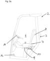
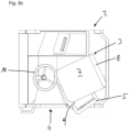
- shows a top view with respect to
Fig. 3a . - Fig. 4a
- shows the
cabin 2 in side view with theseat 3 in forward driving position. - Fig. 4b
- shows a top view with respect to
Fig. 4a . - Fig. 5a
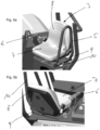
- shows the
seat 3 in an isolated view from the front of theforklift 1. - Fig. 5b
- shows the
seat 3 in an isolated view from the rear of theforklift 1. - The figures show a truck-mounted
forklift 1 having acabin 2 and aseat 3 for use by a driver arranged in thecabin 2. - The
cabin 2 has alateral opening 4 to enter and exit thecabin 2. Theseat 3 is mounted rotatably relative to thecabin 2. - There is provided a
safety bracket 5 for preventing a driver from involuntarily exiting saidcabin 2 through thelateral opening 4 and for providing lateral impact protection. According to the invention thesafety bracket 5 is mechanically connected to theseat 3 to be rotatable together with theseat 3. Thesafety bracket 5 can be used as a handgrab by the driver when entering thecabin 2. - The
safety bracket 5 rotates together with theseat 3 in an upright position. Thesafety bracket 5 extends from the sittingsurface 7 of theseat 3, or more specifically from theseat mounting frame 9 under theseat 3, to an upper end of thebackrest 8 of saidseat 3 and in the shown embodiment extends for a distance beyond the upper end of thebackrest 8. - In the shown embodiment mechanical coupling is being done by rigidly mounting both the
seat 3 and thesafety bracket 5 on a mounting frame 9 (with the possible exception of slidably moving theseat 3 along the mountingframe 9 in order to adjust distance betweenseat 3 and a forward end of thecabin 2 where driving controls are arranged, however thesafety bracket 5 does not have to be slidably mounted to the mounting frame 9). The mountingframe 9 is rotatable relative to thecabin 2 and can be releasably locked by a locking mechanism in two different positions: - a first position in which entry and exit of the
cabin 2 is facilitated - a second position in which the
seat 3 is oriented substantially in a forward driving position looking towards adriving wheel 11 and pedals 12 (note that in the shown embodiment the forward driving position theseat 2 is oriented with an angle about 5° relative to the forward driving direction of the forklift 1). - It would also be feasible to provide a third position in which the
seat 3 is oriented suitable for rearward driving. - In an alternative embodiment, the
seat 3 and thesafety bracket 5, which are mechanically connected, part rotatably to the mountingframe 9. - In the shown embodiment the
seat 3 has to be rotated by the driver without support by a rotation drive except for a spring device which biases the mountingframe 9 in rotation direction from the second to the first position. Arelease lever 10 releases a locking mechanism which locks rotation of the mountingframe 9 in the first and second position. The locking mechanism can comprise a cam that can be swivelled against the force of a spring by therelease lever 10. In the shown embodiment therelease lever 10 is arranged on the left side of the seat 3 (cf.Fig. 5a ) although it could be positioned elsewhere. The shown placement minimizes danger of accidentally opening the locking mechanism. By way of example, to release theseat 3 in the second position it has to be pushed rearward to be rotatable into the first position (rearward motion to enable outward rotation is a natural movement for a driver). A release of theseat 3 in the second position by pushing therelease lever 10 in the opposite, forward position for theseat 3 to be rotatable into the first position can also be envisioned. - To increase comfort for the driver there is provided an
arm rest 6 for the seat 3 (cf.Fig. 5b ). Thearm rest 6 is pivotally mounted to theseat 3. InFig. 5b rotation of theseat 3 into a third position for rearward driving is permitted by pivoting the arm rest 6 (in the shown embodiment by pushing thearm rest 6 outward, i. e. away from the sittingsurface 7 of the seat 3). - As shown in
Figs. 5a and 5b theseat 3 can be provided with a seat belt. - There might be provided a sensor detecting the swivel position of the
seat 3 in order to only allow driving of theforklift 1 if theseat 3 is in forward driving position. -
- 1
- forklift
- 2
- cabin
- 3
- seat
- 4
- lateral opening
- 5
- safety bracket
- 6
- arm rest
- 7
- sitting surface of seat
- 8
- backrest of seat
- 9
- mounting platform of seat
- 10
- release lever
- 11
- driving wheel
- 12
- pedal
Claims (14)
- Forklift (1) having a cabin (2) and a seat (3) for use by a driver arranged in said cabin (2), said cabin (2) having a lateral opening (4) to enter and exit said cabin (2), wherein said seat (3) is mounted rotatably relative to the cabin (2) and wherein there is provided a safety bracket (5) for preventing said driver from involuntarily exiting said cabin (2) through said lateral opening (4) and for providing lateral impact protection, characterized in that said safety bracket (5) extends at least from a sitting surface (7) of said seat (3) to an upper end of a backrest (8) of said seat (3), said safety bracket (5) is mechanically connected to said seat (3) to be rotatable together with said seat (3), wherein the seat (3) and the safety bracket (5) are jointly rotatable with respect to a substantially vertical axis, wherein said seat (3) is rotatable between a first position in which entry and exit of said cabin (2) is facilitated and a second position in which said seat (2) is oriented substantially in a forward driving position.
- Forklift according to the preceding claim, wherein in said forward driving position said seat (2) is oriented with an angle between 3° and 9°, preferably about 5°, relative to the forward driving direction of said forklift (1).
- Forklift according to the preceding claim, wherein said seat (3) is additionally rotatable into a third position suitable for rearward driving.
- Forklift according to at least one of the preceding claims, wherein there is provided at least one arm rest (6) for said seat (3).
- Forklift according to claims 3 and 4, wherein said arm rest (6) is pivotally mounted to said seat (3) and rotation of said seat (3) into said third position is permitted by pivoting said arm rest (6).
- Forklift according to at least one of the preceding claims, wherein there is provided a locking mechanism for releasably locking rotation of said seat (3) in at least one position.
- Forklift according to the preceding claim, wherein there is provided a release device for releasing said locking mechanism and allowing rotation of said seat (3).
- Forklift according to at least one of the preceding claims, wherein a sitting surface (7) of said seat (3) tapers in a direction away from a backrest (8) of said seat (3).
- Forklift according to at least one of the preceding claims, wherein there is provided another safety bracket (5) on the other side of said seat (3).
- Forklift according to at least one of the preceding claims, wherein there is provided a rotation drive for rotating said seat (3).
- Forklift according to at least one of the preceding claims, wherein said safety bracket (5) is rigidly mounted to a mounting platform (9) of said seat (3).
- Forklift according to at least one of the preceding claims, wherein said safety bracket (5) is pivotably mounted relative to said seat (3).
- Forklift according to at least one of the preceding claims, wherein rotation of said seat (3) is mechanically biased by way of a spring device in one of the rotational directions of said seat (3).
- Forklift according to at least one of the preceding claims, wherein said forklift (1) is a truck-mounted forklift.
Priority Applications (5)
| Application Number | Priority Date | Filing Date | Title |
|---|---|---|---|
| EP17189038.7A EP3450386B1 (en) | 2017-09-01 | 2017-09-01 | Forklift |
| PL17189038.7T PL3450386T3 (en) | 2017-09-01 | 2017-09-01 | Forklift |
| PCT/EP2018/073211 WO2019043048A1 (en) | 2017-09-01 | 2018-08-29 | Forklift |
| US16/804,609 US11603299B2 (en) | 2017-09-01 | 2020-02-28 | Forklift |
| US18/104,542 US11827501B2 (en) | 2017-09-01 | 2023-02-01 | Forklift |
Applications Claiming Priority (1)
| Application Number | Priority Date | Filing Date | Title |
|---|---|---|---|
| EP17189038.7A EP3450386B1 (en) | 2017-09-01 | 2017-09-01 | Forklift |
Publications (3)
| Publication Number | Publication Date |
|---|---|
| EP3450386A1 EP3450386A1 (en) | 2019-03-06 |
| EP3450386B1 true EP3450386B1 (en) | 2024-11-13 |
| EP3450386C0 EP3450386C0 (en) | 2024-11-13 |
Family
ID=59761848
Family Applications (1)
| Application Number | Title | Priority Date | Filing Date |
|---|---|---|---|
| EP17189038.7A Active EP3450386B1 (en) | 2017-09-01 | 2017-09-01 | Forklift |
Country Status (4)
| Country | Link |
|---|---|
| US (2) | US11603299B2 (en) |
| EP (1) | EP3450386B1 (en) |
| PL (1) | PL3450386T3 (en) |
| WO (1) | WO2019043048A1 (en) |
Families Citing this family (4)
| Publication number | Priority date | Publication date | Assignee | Title |
|---|---|---|---|---|
| PL3450386T3 (en) * | 2017-09-01 | 2025-03-17 | Palfinger Ag | Forklift |
| EP3904273A4 (en) * | 2018-12-27 | 2022-08-17 | Mitsubishi Logisnext Co., Ltd. | Forklift |
| CN110734010B (en) * | 2019-10-31 | 2021-12-24 | 安徽高品塑胶科技有限公司 | Forklift canopy |
| EP4711198A1 (en) | 2024-09-13 | 2026-03-18 | Palfinger AG | Slave stacker |
Citations (2)
| Publication number | Priority date | Publication date | Assignee | Title |
|---|---|---|---|---|
| US20070261908A1 (en) * | 2006-05-12 | 2007-11-15 | Crown Equipment Corporation | Seat deck assembly or compartment cover for a materials handling vehicle |
| US8444212B2 (en) * | 2008-05-15 | 2013-05-21 | Iws Ingenieurgesellschaft Weiner & Schroeter Mbh | Driver protection system for a vehicle |
Family Cites Families (27)
| Publication number | Priority date | Publication date | Assignee | Title |
|---|---|---|---|---|
| DE1753009C3 (en) * | 1968-03-13 | 1979-11-29 | Recaro Gmbh & Co, 7000 Stuttgart | Backrest for a vehicle seat |
| US4241893A (en) * | 1979-05-11 | 1980-12-30 | Sears Manufacturing Co. | Adjustable seat assembly |
| US4262958A (en) * | 1979-09-07 | 1981-04-21 | Eaton Corporation | Adjustable seat for an industrial vehicle |
| US4537446A (en) | 1983-08-04 | 1985-08-27 | Clark Equipment Company | Safety seat |
| US4623196A (en) * | 1983-09-14 | 1986-11-18 | Clark Equipment Company | Safety seat assembly for industrial vehicles |
| US5050700A (en) * | 1989-06-05 | 1991-09-24 | Daewoo Heavy Industries Ltd. | Safety apparatus for a skid-steer loader |
| US5938237A (en) * | 1994-10-20 | 1999-08-17 | Linde Aktiengesellschaft | Driver restraint device for an industrial truck |
| DE19615591A1 (en) * | 1996-04-19 | 1997-10-23 | Linde Ag | Fork-lift driver safety restraint |
| DE19932256B4 (en) * | 1999-07-10 | 2005-03-31 | Hans Klaus Wallburg | Industrial truck with a safety cell for a driver |
| KR100655191B1 (en) * | 2000-03-01 | 2006-12-08 | 티씨엠 가부시키가이샤 | Industrial vehicle |
| EP1145919B1 (en) * | 2000-04-14 | 2005-06-29 | Hans Sauermann | Safety device for a driver of a handling vehicle, in particular |
| DE10119770A1 (en) * | 2001-04-23 | 2002-11-07 | Trw Repa Gmbh | Inflatable side airbag |
| US6732829B2 (en) * | 2002-01-04 | 2004-05-11 | Clark Equipment Company | Load absorbing operator restraint bar |
| DE20202522U1 (en) * | 2002-02-18 | 2002-07-04 | Sauermann, Hans, 85119 Ernsgaden | Restraint system for a driver of a vehicle |
| US6679349B1 (en) * | 2002-02-20 | 2004-01-20 | Robert W. Pollish, Jr. | Fork lift apparatus |
| US6902024B2 (en) * | 2002-11-27 | 2005-06-07 | Clark Equipment Company | Lateral operator restraint system and position sensor for material handler |
| US7059680B2 (en) * | 2004-09-23 | 2006-06-13 | Crown Equipment Corporation | Seat repositioning device with release on control handle |
| US7121608B2 (en) | 2004-09-23 | 2006-10-17 | Crown Equipment Corporation | Rotating and/or swiveling seat |
| US7520567B2 (en) * | 2004-09-23 | 2009-04-21 | Crown Equipment Corporation | Systems and methods for seat repositioning |
| JP4595897B2 (en) * | 2006-07-24 | 2010-12-08 | 株式会社豊田自動織機 | Rotating seat for vehicle |
| JP4595908B2 (en) * | 2006-08-11 | 2010-12-08 | 株式会社豊田自動織機 | Rotating seat locking mechanism |
| US7677647B2 (en) * | 2008-01-31 | 2010-03-16 | Cnh America Llc | Adjustable mounting restraint device |
| US8210613B2 (en) * | 2008-09-22 | 2012-07-03 | Crown Equipment Corporation | Swivel seat with adjustable swivel resistance |
| US7971677B2 (en) * | 2009-01-27 | 2011-07-05 | Clark Equipment Company | Work machine vehicle having seat mounted controls with nested seatbar |
| RU2556802C2 (en) * | 2010-11-05 | 2015-07-20 | Вольво Констракшн Эквипмент Аб | Construction machine with improved ergonomics of control organs |
| CA3046808A1 (en) * | 2016-12-16 | 2018-06-21 | Clark Equipment Company | Loader with telescopic lift arm |
| PL3450386T3 (en) * | 2017-09-01 | 2025-03-17 | Palfinger Ag | Forklift |
-
2017
- 2017-09-01 PL PL17189038.7T patent/PL3450386T3/en unknown
- 2017-09-01 EP EP17189038.7A patent/EP3450386B1/en active Active
-
2018
- 2018-08-29 WO PCT/EP2018/073211 patent/WO2019043048A1/en not_active Ceased
-
2020
- 2020-02-28 US US16/804,609 patent/US11603299B2/en active Active
-
2023
- 2023-02-01 US US18/104,542 patent/US11827501B2/en active Active
Patent Citations (2)
| Publication number | Priority date | Publication date | Assignee | Title |
|---|---|---|---|---|
| US20070261908A1 (en) * | 2006-05-12 | 2007-11-15 | Crown Equipment Corporation | Seat deck assembly or compartment cover for a materials handling vehicle |
| US8444212B2 (en) * | 2008-05-15 | 2013-05-21 | Iws Ingenieurgesellschaft Weiner & Schroeter Mbh | Driver protection system for a vehicle |
Also Published As
| Publication number | Publication date |
|---|---|
| US11603299B2 (en) | 2023-03-14 |
| US11827501B2 (en) | 2023-11-28 |
| PL3450386T3 (en) | 2025-03-17 |
| WO2019043048A1 (en) | 2019-03-07 |
| US20200198949A1 (en) | 2020-06-25 |
| EP3450386A1 (en) | 2019-03-06 |
| EP3450386C0 (en) | 2024-11-13 |
| US20230174360A1 (en) | 2023-06-08 |
Similar Documents
| Publication | Publication Date | Title |
|---|---|---|
| US11827501B2 (en) | Forklift | |
| JP5961754B2 (en) | Adjustable vehicle seat | |
| KR101256557B1 (en) | Foldable armrest | |
| EP2057055B1 (en) | Chair-lift chair safety device with a crossbar lock-release control device | |
| US7740319B2 (en) | Headrests for vehicle seats | |
| US7472963B2 (en) | Recliner lever assembly for a front seat of a vehicle | |
| JP2003291710A (en) | Industrial vehicle | |
| JP4658582B2 (en) | Safety lever operating structure of the hood latch assembly | |
| GB2144323A (en) | Safety seat assembly | |
| CN104411538B (en) | adjustable vehicle seat | |
| EP2105346A2 (en) | Seat apparatus for vehicle | |
| US20210339657A1 (en) | Reactive and dissipative recliner system for a vehicle seat | |
| JP2016179722A (en) | Bicycle parking equipment | |
| JP2015503481A (en) | Release device for vehicle seat with easy-to-ride function and method for operating the release device | |
| EP4408785A1 (en) | Machine for handling a load or a person | |
| US10315540B2 (en) | Inertia stop link for stadium style seat cushion stowed positioning | |
| JP2006503746A (en) | Limiting device for a vehicle seat, in particular for pivotable elements | |
| JP3766658B2 (en) | Locking device for seat structure | |
| JP5577861B2 (en) | Vehicle seat | |
| JP7072533B2 (en) | Driver's seat rotation lock mechanism | |
| JP3614130B2 (en) | Vehicle seat device | |
| JP2008528076A5 (en) | ||
| JP3517138B2 (en) | Variable position and attitude device for automotive seats | |
| JPH05147463A (en) | Seat device | |
| TH53714A (en) | Folding stroller |
Legal Events
| Date | Code | Title | Description |
|---|---|---|---|
| PUAI | Public reference made under article 153(3) epc to a published international application that has entered the european phase |
Free format text: ORIGINAL CODE: 0009012 |
|
| STAA | Information on the status of an ep patent application or granted ep patent |
Free format text: STATUS: THE APPLICATION HAS BEEN PUBLISHED |
|
| AK | Designated contracting states |
Kind code of ref document: A1 Designated state(s): AL AT BE BG CH CY CZ DE DK EE ES FI FR GB GR HR HU IE IS IT LI LT LU LV MC MK MT NL NO PL PT RO RS SE SI SK SM TR |
|
| AX | Request for extension of the european patent |
Extension state: BA ME |
|
| STAA | Information on the status of an ep patent application or granted ep patent |
Free format text: STATUS: REQUEST FOR EXAMINATION WAS MADE |
|
| 17P | Request for examination filed |
Effective date: 20190904 |
|
| RBV | Designated contracting states (corrected) |
Designated state(s): AL AT BE BG CH CY CZ DE DK EE ES FI FR GB GR HR HU IE IS IT LI LT LU LV MC MK MT NL NO PL PT RO RS SE SI SK SM TR |
|
| STAA | Information on the status of an ep patent application or granted ep patent |
Free format text: STATUS: EXAMINATION IS IN PROGRESS |
|
| 17Q | First examination report despatched |
Effective date: 20221208 |
|
| P01 | Opt-out of the competence of the unified patent court (upc) registered |
Effective date: 20230530 |
|
| RIC1 | Information provided on ipc code assigned before grant |
Ipc: B60R 21/00 20060101ALI20240422BHEP Ipc: B60N 2/14 20060101ALI20240422BHEP Ipc: B66F 17/00 20060101ALI20240422BHEP Ipc: B66F 9/075 20060101AFI20240422BHEP Ipc: B60N 2/28 20060101ALI20240422BHEP Ipc: B60N 2/24 20060101ALI20240422BHEP Ipc: B60R 21/02 20060101ALI20240422BHEP |
|
| GRAP | Despatch of communication of intention to grant a patent |
Free format text: ORIGINAL CODE: EPIDOSNIGR1 |
|
| STAA | Information on the status of an ep patent application or granted ep patent |
Free format text: STATUS: GRANT OF PATENT IS INTENDED |
|
| INTG | Intention to grant announced |
Effective date: 20240611 |
|
| RIN1 | Information on inventor provided before grant (corrected) |
Inventor name: KALIN, MATTHIAS Inventor name: KEENAN, PATRICK Inventor name: O'KEEFFE, ERIC |
|
| GRAS | Grant fee paid |
Free format text: ORIGINAL CODE: EPIDOSNIGR3 |
|
| GRAA | (expected) grant |
Free format text: ORIGINAL CODE: 0009210 |
|
| STAA | Information on the status of an ep patent application or granted ep patent |
Free format text: STATUS: THE PATENT HAS BEEN GRANTED |
|
| AK | Designated contracting states |
Kind code of ref document: B1 Designated state(s): AL AT BE BG CH CY CZ DE DK EE ES FI FR GB GR HR HU IE IS IT LI LT LU LV MC MK MT NL NO PL PT RO RS SE SI SK SM TR |
|
| REG | Reference to a national code |
Ref country code: GB Ref legal event code: FG4D |
|
| REG | Reference to a national code |
Ref country code: CH Ref legal event code: EP |
|
| REG | Reference to a national code |
Ref country code: IE Ref legal event code: FG4D |
|
| REG | Reference to a national code |
Ref country code: DE Ref legal event code: R096 Ref document number: 602017086071 Country of ref document: DE |
|
| U01 | Request for unitary effect filed |
Effective date: 20241205 |
|
| U07 | Unitary effect registered |
Designated state(s): AT BE BG DE DK EE FI FR IT LT LU LV MT NL PT RO SE SI Effective date: 20241216 |
|
| P04 | Withdrawal of opt-out of the competence of the unified patent court (upc) registered |
Free format text: CASE NUMBER: APP_65529/2024 Effective date: 20241212 |
|
| PG25 | Lapsed in a contracting state [announced via postgrant information from national office to epo] |
Ref country code: HR Free format text: LAPSE BECAUSE OF FAILURE TO SUBMIT A TRANSLATION OF THE DESCRIPTION OR TO PAY THE FEE WITHIN THE PRESCRIBED TIME-LIMIT Effective date: 20241113 Ref country code: IS Free format text: LAPSE BECAUSE OF FAILURE TO SUBMIT A TRANSLATION OF THE DESCRIPTION OR TO PAY THE FEE WITHIN THE PRESCRIBED TIME-LIMIT Effective date: 20250313 |
|
| PG25 | Lapsed in a contracting state [announced via postgrant information from national office to epo] |
Ref country code: ES Free format text: LAPSE BECAUSE OF FAILURE TO SUBMIT A TRANSLATION OF THE DESCRIPTION OR TO PAY THE FEE WITHIN THE PRESCRIBED TIME-LIMIT Effective date: 20241113 |
|
| PG25 | Lapsed in a contracting state [announced via postgrant information from national office to epo] |
Ref country code: NO Free format text: LAPSE BECAUSE OF FAILURE TO SUBMIT A TRANSLATION OF THE DESCRIPTION OR TO PAY THE FEE WITHIN THE PRESCRIBED TIME-LIMIT Effective date: 20250213 |
|
| PG25 | Lapsed in a contracting state [announced via postgrant information from national office to epo] |
Ref country code: GR Free format text: LAPSE BECAUSE OF FAILURE TO SUBMIT A TRANSLATION OF THE DESCRIPTION OR TO PAY THE FEE WITHIN THE PRESCRIBED TIME-LIMIT Effective date: 20250214 |
|
| PG25 | Lapsed in a contracting state [announced via postgrant information from national office to epo] |
Ref country code: RS Free format text: LAPSE BECAUSE OF FAILURE TO SUBMIT A TRANSLATION OF THE DESCRIPTION OR TO PAY THE FEE WITHIN THE PRESCRIBED TIME-LIMIT Effective date: 20250213 |
|
| PG25 | Lapsed in a contracting state [announced via postgrant information from national office to epo] |
Ref country code: SM Free format text: LAPSE BECAUSE OF FAILURE TO SUBMIT A TRANSLATION OF THE DESCRIPTION OR TO PAY THE FEE WITHIN THE PRESCRIBED TIME-LIMIT Effective date: 20241113 |
|
| PG25 | Lapsed in a contracting state [announced via postgrant information from national office to epo] |
Ref country code: SK Free format text: LAPSE BECAUSE OF FAILURE TO SUBMIT A TRANSLATION OF THE DESCRIPTION OR TO PAY THE FEE WITHIN THE PRESCRIBED TIME-LIMIT Effective date: 20241113 |
|
| PG25 | Lapsed in a contracting state [announced via postgrant information from national office to epo] |
Ref country code: CZ Free format text: LAPSE BECAUSE OF FAILURE TO SUBMIT A TRANSLATION OF THE DESCRIPTION OR TO PAY THE FEE WITHIN THE PRESCRIBED TIME-LIMIT Effective date: 20241113 |
|
| PLBE | No opposition filed within time limit |
Free format text: ORIGINAL CODE: 0009261 |
|
| STAA | Information on the status of an ep patent application or granted ep patent |
Free format text: STATUS: NO OPPOSITION FILED WITHIN TIME LIMIT |
|
| PGFP | Annual fee paid to national office [announced via postgrant information from national office to epo] |
Ref country code: PL Payment date: 20250820 Year of fee payment: 9 |
|
| PGFP | Annual fee paid to national office [announced via postgrant information from national office to epo] |
Ref country code: GB Payment date: 20250923 Year of fee payment: 9 |
|
| 26N | No opposition filed |
Effective date: 20250814 |
|
| PGFP | Annual fee paid to national office [announced via postgrant information from national office to epo] |
Ref country code: IE Payment date: 20250917 Year of fee payment: 9 |
|
| U20 | Renewal fee for the european patent with unitary effect paid |
Year of fee payment: 9 Effective date: 20250924 |
|
| REG | Reference to a national code |
Ref country code: CH Ref legal event code: H13 Free format text: ST27 STATUS EVENT CODE: U-0-0-H10-H13 (AS PROVIDED BY THE NATIONAL OFFICE) Effective date: 20260425 |