EP3450377A1 - Sheave for belt with profile tracking features - Google Patents
Sheave for belt with profile tracking features Download PDFInfo
- Publication number
- EP3450377A1 EP3450377A1 EP18190835.1A EP18190835A EP3450377A1 EP 3450377 A1 EP3450377 A1 EP 3450377A1 EP 18190835 A EP18190835 A EP 18190835A EP 3450377 A1 EP3450377 A1 EP 3450377A1
- Authority
- EP
- European Patent Office
- Prior art keywords
- tracking
- sheave
- belt
- grooves
- assembly
- Prior art date
- Legal status (The legal status is an assumption and is not a legal conclusion. Google has not performed a legal analysis and makes no representation as to the accuracy of the status listed.)
- Granted
Links
Images




Classifications
-
- B—PERFORMING OPERATIONS; TRANSPORTING
- B66—HOISTING; LIFTING; HAULING
- B66B—ELEVATORS; ESCALATORS OR MOVING WALKWAYS
- B66B11/00—Main component parts of lifts in, or associated with, buildings or other structures
- B66B11/04—Driving gear ; Details thereof, e.g. seals
- B66B11/08—Driving gear ; Details thereof, e.g. seals with hoisting rope or cable operated by frictional engagement with a winding drum or sheave
-
- B—PERFORMING OPERATIONS; TRANSPORTING
- B66—HOISTING; LIFTING; HAULING
- B66B—ELEVATORS; ESCALATORS OR MOVING WALKWAYS
- B66B15/00—Main component parts of mining-hoist winding devices
- B66B15/02—Rope or cable carriers
- B66B15/04—Friction sheaves; "Koepe" pulleys
-
- B—PERFORMING OPERATIONS; TRANSPORTING
- B66—HOISTING; LIFTING; HAULING
- B66B—ELEVATORS; ESCALATORS OR MOVING WALKWAYS
- B66B7/00—Other common features of elevators
- B66B7/06—Arrangements of ropes or cables
- B66B7/062—Belts
-
- F—MECHANICAL ENGINEERING; LIGHTING; HEATING; WEAPONS; BLASTING
- F16—ENGINEERING ELEMENTS AND UNITS; GENERAL MEASURES FOR PRODUCING AND MAINTAINING EFFECTIVE FUNCTIONING OF MACHINES OR INSTALLATIONS; THERMAL INSULATION IN GENERAL
- F16G—BELTS, CABLES, OR ROPES, PREDOMINANTLY USED FOR DRIVING PURPOSES; CHAINS; FITTINGS PREDOMINANTLY USED THEREFOR
- F16G1/00—Driving-belts
- F16G1/14—Driving-belts made of plastics
- F16G1/16—Driving-belts made of plastics with reinforcement bonded by the plastic material
-
- F—MECHANICAL ENGINEERING; LIGHTING; HEATING; WEAPONS; BLASTING
- F16—ENGINEERING ELEMENTS AND UNITS; GENERAL MEASURES FOR PRODUCING AND MAINTAINING EFFECTIVE FUNCTIONING OF MACHINES OR INSTALLATIONS; THERMAL INSULATION IN GENERAL
- F16H—GEARING
- F16H55/00—Elements with teeth or friction surfaces for conveying motion; Worms, pulleys or sheaves for gearing mechanisms
- F16H55/32—Friction members
- F16H55/36—Pulleys
- F16H55/50—Features essential to rope pulleys
-
- D—TEXTILES; PAPER
- D07—ROPES; CABLES OTHER THAN ELECTRIC
- D07B—ROPES OR CABLES IN GENERAL
- D07B1/00—Constructional features of ropes or cables
- D07B1/22—Flat or flat-sided ropes; Sets of ropes consisting of a series of parallel ropes
-
- D—TEXTILES; PAPER
- D07—ROPES; CABLES OTHER THAN ELECTRIC
- D07B—ROPES OR CABLES IN GENERAL
- D07B2501/00—Application field
- D07B2501/20—Application field related to ropes or cables
- D07B2501/2007—Elevators
-
- D—TEXTILES; PAPER
- D07—ROPES; CABLES OTHER THAN ELECTRIC
- D07B—ROPES OR CABLES IN GENERAL
- D07B5/00—Making ropes or cables from special materials or of particular form
- D07B5/005—Making ropes or cables from special materials or of particular form characterised by their outer shape or surface properties
- D07B5/006—Making ropes or cables from special materials or of particular form characterised by their outer shape or surface properties by the properties of an outer surface polymeric coating
Definitions
- Embodiments disclosed herein relate to elevator systems, and more particularly to load bearing members to suspend and/or drive elevator cars of an elevator system.
- Elevator systems are useful for carrying passengers, cargo, or both, between various levels in a building.
- Some elevators are traction based and utilize load bearing members such as belts for supporting the elevator car and achieving the desired movement and positioning of the elevator car.
- a plurality of tension members are embedded in a common jacket.
- the jacket retains the tension members in desired positions and provides a frictional load path.
- a machine drives a traction sheave with which the belts interact to drive the elevator car along a hoistway.
- Belts typically utilize tension members formed from steel elements, but alternatively may utilize tension members formed from synthetic fibers or other materials, such as carbon fiber composites.
- belts are utilized as load bearing members, and are routed laterally adjacently over the traction sheave.
- One challenge is providing enough strength and stiffness per sheave width for the system, and an important element of this is how closely the belts can be positioned.
- the belt positioning is affected by the accuracy of belt tracking which can be affected not only by machine sheave alignment but also by hoistway rail positioning and building sway or drift.
- a belt and sheave assembly for an elevator system includes a sheave having a plurality of tracking grooves laterally spaced across a sheave width, and a debris channel located in a tracking groove of the plurality of tracking grooves defining a radially inwardmost extent of the tracking groove.
- the assembly further includes a belt having a plurality of tension members arranged along a belt width and extending longitudinally along a length of the belt, a jacket at least partially enclosing the plurality of tension members, the jacket defining a side of the belt configured to interface with the sheave, and a plurality of tracking features extending from the side of the belt.
- the plurality of tracking features are laterally spaced across the belt width. Each tracking feature is configured to be received in a tracking groove of the plurality of tracking grooves, and each tension member is laterally offset from each of the tracking features of the plurality of tracking features.
- a sheave surface is defined between adjacent tracking grooves of the plurality of tracking grooves, and a tracking feature gap is defined between adjacent tracking features .
- each tension member of the plurality of tension members is located over a sheave surface of the plurality of sheave surfaces.
- the debris channel is positioned radially inward of the radial extent of the corresponding tracking feature.
- the tracking groove is substantially triangular in cross-sectional shape.
- the tracking feature is substantially triangular in cross-sectional shape.
- the plurality of tracking features are formed from a first material, and the jacket is formed from a second material different from the first material.
- the first material has a lower coefficient of friction than the second material.
- a tracking groove of the plurality of tracking grooves has a lower coefficient of friction than the sheave surface.
- a cleaning element is insertable into the debris channel configured to remove accumulated debris from the debris channel.
- an elevator system in another embodiment, includes a hoistway, an elevator car located in the hoistway and movable therein, a sheave including a plurality of tracking grooves laterally spaced across a sheave width, and a debris channel located in a tracking groove of the plurality of tracking grooves, defining a radially inwardmost extent of the tracking groove.
- a belt is operably connected to the elevator car to suspend and/or drive the elevator car along the hoistway, the belt including a plurality of tension members arranged along a belt width and extending longitudinally along a length of the belt, a jacket at least partially enclosing the plurality of tension members, the jacket defining a side of the belt configured to interface with the sheave, and a plurality of tracking features extending from the side of the belt, the plurality of tracking features laterally spaced across the belt width.
- Each tracking feature is configured to be received in a tracking groove of the plurality of tracking grooves, and each tension member is laterally offset from each of the tracking features of the plurality of tracking features.
- a sheave surface is defined between adjacent tracking grooves of the plurality of tracking grooves, and a tracking feature gap is defined between adjacent tracking features.
- each tension member of the plurality of tension members is located over a sheave surface of the plurality of sheave surfaces.
- the debris channel is located radially inward of the radial extent of the corresponding tracking feature.
- the tracking groove is substantially triangular in cross-sectional shape.
- the tracking feature is substantially triangular in cross-sectional shape.
- the plurality of tracking features are formed from a first material, and the jacket is formed from a second material different from the first material, the first material having a lower coefficient of friction than the second material.
- a cleaning element is insertable into the debris channel configured to remove accumulated debris from the debris channel.
- a sheave for an elevator system includes a plurality of tracking grooves laterally spaced across a sheave width and a debris channel located in a tracking groove of the plurality of tracking grooves, defining a radially inwardmost extent of the tracking groove.
- Each tracking groove of the plurality of tracking grooves is configured to receive a corresponding tracking feature of a belt of an elevator system.
- a sheave surface is defined between adjacent tracking grooves of the plurality of tracking grooves.
- FIG. 1 Shown in FIG. 1 is a schematic view of an exemplary traction elevator system 10.
- the elevator system 10 includes an elevator car 14 operatively suspended or supported in a hoistway 12 with one or more belts 16.
- the one or more belts 16 interact with sheaves 18 and 52 to be routed around various components of the elevator system 10.
- Sheave 18 is configured as a diverter, deflector or idler sheave and sheave 52 is configured as a traction sheave 52, driven by a machine 50.
- Movement of the traction sheave 52 by the machine 50 drives, moves and/or propels (through traction) the one or more belts 16 that are routed around the traction sheave 52.
- Diverter, deflector or idler sheaves 18 are not driven by a machine 50, but help guide the one or more belts 16 around the various components of the elevator system 10.
- the one or more belts 16 could also be connected to a counterweight 22, which is used to help balance the elevator system 10 and reduce the difference in belt tension on both sides of the traction sheave during operation.
- the sheaves 18 and 52 each have a diameter, which may be the same or different from each other.
- the elevator system 10 could use two or more belts 16 for suspending and/or driving the elevator car 14
- the elevator system 10 could have various configurations such that either both sides of the one or more belts 16 engage the sheaves 18, 52 or only one side of the one or more belts 16 engages the sheaves 18, 52.
- the embodiment of FIG 1 shows a 1:1 roping arrangement in which the one or more belts 16 terminate at the car 14 and counterweight 22, while other embodiments may utilize other roping arrangements.
- the belts 16 are constructed to meet belt life requirements and have smooth operation, while being sufficiently strong to be capable of meeting strength requirements for suspending and/or driving the elevator car 14 and counterweight 22.
- FIG. 2 provides a cross-sectional schematic of an exemplary belt 16 construction or design.
- the belt 16 includes a plurality of tension members 24 extending longitudinally along the belt 16 and arranged across a belt width 26.
- the tension members 24 are at least partially enclosed in a jacket material 28 to restrain movement of the tension members 24 in the belt 16 and to protect the tension members 24.
- the jacket material 28 defines a traction side 30 configured to interact with a corresponding surface of the traction sheave 52.
- Exemplary materials for the jacket material 28 include the elastomers of thermoplastic and thermosetting polyurethanes, thermoplastic polyester elastomers, ethylene propylene diene elastomer, chloroprene, chlorosulfonyl polyethylene, ethylene vinyl acetate, polyamide, polypropylene, butyl rubber, acrylonitrile butadiene rubber, styrene butadiene rubber, acrylic elastomer, fluoroelastomer, silicone elastomer, polyolefin elastomer, styrene block and diene elastomer, natural rubber, or combinations thereof.
- Other materials may be used to form the jacket material 28 if they are adequate to meet the required functions of the belt 16.
- a primary function of the jacket material 28 is to provide a sufficient coefficient of friction between the belt 16 and the traction sheave 52 to produce a desired amount of traction therebetween.
- the jacket material 28 should also transmit the traction loads to the tension members 24.
- the jacket material 28 should be wear resistant and protect the tension members 24 from impact damage, exposure to environmental factors, such as chemicals, for example.
- the belt 16 has a belt width 26 and a belt thickness 32, with an aspect ratio of belt width 26 to belt thickness 32 greater than one.
- the belt 16 further includes a back side 34 opposite the traction side 30 and belt edges 36 extending between the traction side 30 and the back side 34. While five tension members 24 are illustrated in the embodiment of FIG. 2 , other embodiments may include other numbers of tension members 24, for example, 6, 10 or 12 tension members 24. Further, while the tension members 24 of the embodiment of FIG. 2 are substantially identical, in other embodiments, the tension members 24 may differ from one another.
- the tension member 24 may be a plurality of wires 38, for example, steel wires 38, which in some embodiments are formed into one or more strands 40.
- the tension member 24 may include a plurality of fibers 42, such as carbon fiber, glass fiber or aramid fiber, disposed in a matrix material 44. Materials such as polyurethane, vinylester, or epoxy may be utilized as the matrix material.
- the belt 16 includes one or more tracking features 46 at the traction side 30.
- the tracking features 46 are protrusions from the traction side 30, and may be triangular in shape as shown. It is to be appreciated, however, that while triangular-shaped tracking features are shown in FIG. 2 , other shapes such as, for example, semi-circular or trapezoidal may be utilized. Further, while in the embodiment shown the tracking features 46 are located at the traction side 30, in other embodiments the tracking features 46 are alternatively or additionally located at the back side 34.
- the tracking features 46 may be formed with the jacket material 28 from the same material via, for example, an extrusion process.
- the tracking features 46 may be formed from a material different from that of the jacket material 28 for, for example, improved wear resistance, stiffness or durability.
- the tracking features 46 may be formed from material having a lower coefficient of friction than a coefficient of friction of the jacket material 28.
- the tracking features 46 may be coextruded with the jacket material 28, or may alternatively formed separately and adhered or otherwise secured to the traction side 30.
- the tracking features 46 are arrayed across the belt width 26, and are spaced apart by a tracking feature gap 54, defined as a distance along the traction side 30 between adjacent tracking features 46.
- the tracking features 46 and tension members 24 are positioned such that the tracking features are 46 are located laterally between adjacent tension members 24 and over the tracking feature gaps 54, with the tension member 24 centered over its corresponding tracking feature gap 54. Further, the tracking features 46 may be evenly spaced across the belt width 26, or in some embodiments may have unequal lateral spacing to provide improved tracking at certain portions of the belt 16, such as nearer the lateral ends of the belt 16. In other embodiments, the tension members 24 are located over the tracking features 46, rather than over the tracking feature gaps 54.
- the traction sheave 52 includes complimentary tracking grooves 56 to receive the tracking features 46 of the belt 16.
- tracking grooves 56 may be disposed at another sheave 18 of the elevator system 10, such as a deflector and/or idler sheave 18.
- the tracking grooves 56 each include a V-shaped groove portion 58 in which the tracking features 46 are positioned.
- the tracking grooves 56 may be otherwise shaped to receive tracking features 46 of shapes other than triangular.
- the tracking grooves 56 each further include a debris channel 60 located at a radially inwardmost extent of the tracking groove 56.
- the debris channel 60 is configured to collect wear debris and external debris such as deposited dust from the belt 16, and in particular from the tracking features 46 and the traction side 30 as they pass over the traction sheave 52.
- the debris channel 60 has a rectangular cross-sectional shape, but in other embodiments other cross-sectional shapes such as triangular or circular may be utilized.
- a cleaning element 68 such as a brush, rod, finger or other element, is inserted into the debris channel 60, at a sheave position away from the belt 16 to remove accumulated debris from the debris channel 60. Such debris removal
- the tracking grooves 56 are laterally spaced across the traction sheave 52 with a sheave surface 62 defined between adjacent tracking grooves 56.
- the sheave surfaces 62 are positioned below the tension members 24 of the belt 16, and in some embodiments have a surface width 64 smaller than a tension member width 66. Further, in some embodiments, the surface width 64 is between 1 ⁇ 4 and 3 ⁇ 4 of the tension member width 66.
- the sheave surface 62 may be substantially flat, or alternatively may be shaped to match an outer surface of the tension member 24. Further, in some embodiments, the tracking grooves 46 may have a lower coefficient of friction than the sheave surface 62. This may be achieved through, for example, the use of coatings or other surface finishes.
- the sheave surface 62 may extend continuously under two or more tension members 24, such as at a centermost section of the traction sheave 52, while tracking grooves 56 are located at an edge portion laterally outboard of the centermost section.
- tension members 24 may be unequal in effective diameter.
- tension members 24 located at the centermost section may have a greater effective diameter than tension members 24 located at the edge portion.
- laterally adjacent tracking features 46 substantially abut one another such that the belt 16 does not include a tracking feature gap 54 between the adjacent tracking features 46.
- the traction sheave 52, and/or deflector and/or idler sheave 18 includes adjacent tracking grooves 56, which substantially abut one another, such that the sheave 18/52 is absent a sheave surface 62 between the adjacent tracking grooves 56.
- the tension members 24 are arranged such that a lateral center of each tension member 24 is laterally offset from a lateral center of each of the tracking features 46 in a belt width 26 direction.
- the arrangements disclosed herein ensure tight spacing of the belts 16 on the traction sheave 52 in elevator systems 10 where multiple belts 16 are utilized, and reduces an overall drive sheave 52 width. Further, since the tension members 24 are well supported by the sheave surfaces 62, loading of the tracking features 46 of the belt 16 is reduced, improving wear performance of the belt 16 and reducing a susceptibility to belt split between the tension members 24.
Landscapes
- Engineering & Computer Science (AREA)
- General Engineering & Computer Science (AREA)
- Mechanical Engineering (AREA)
- Civil Engineering (AREA)
- Structural Engineering (AREA)
- Lift-Guide Devices, And Elevator Ropes And Cables (AREA)
- Cage And Drive Apparatuses For Elevators (AREA)
Abstract
Description
- Embodiments disclosed herein relate to elevator systems, and more particularly to load bearing members to suspend and/or drive elevator cars of an elevator system.
- Elevator systems are useful for carrying passengers, cargo, or both, between various levels in a building. Some elevators are traction based and utilize load bearing members such as belts for supporting the elevator car and achieving the desired movement and positioning of the elevator car.
- Where a belt is used as a load bearing member, a plurality of tension members are embedded in a common jacket. The jacket retains the tension members in desired positions and provides a frictional load path. In an exemplary traction elevator system, a machine drives a traction sheave with which the belts interact to drive the elevator car along a hoistway. Belts typically utilize tension members formed from steel elements, but alternatively may utilize tension members formed from synthetic fibers or other materials, such as carbon fiber composites.
- In many elevator systems, multiple belts are utilized as load bearing members, and are routed laterally adjacently over the traction sheave. One challenge is providing enough strength and stiffness per sheave width for the system, and an important element of this is how closely the belts can be positioned. The belt positioning is affected by the accuracy of belt tracking which can be affected not only by machine sheave alignment but also by hoistway rail positioning and building sway or drift.
- In one embodiment, a belt and sheave assembly for an elevator system includes a sheave having a plurality of tracking grooves laterally spaced across a sheave width, and a debris channel located in a tracking groove of the plurality of tracking grooves defining a radially inwardmost extent of the tracking groove. The assembly further includes a belt having a plurality of tension members arranged along a belt width and extending longitudinally along a length of the belt, a jacket at least partially enclosing the plurality of tension members, the jacket defining a side of the belt configured to interface with the sheave, and a plurality of tracking features extending from the side of the belt. The plurality of tracking features are laterally spaced across the belt width. Each tracking feature is configured to be received in a tracking groove of the plurality of tracking grooves, and each tension member is laterally offset from each of the tracking features of the plurality of tracking features.
- Additionally or alternatively, in this or other embodiments a sheave surface is defined between adjacent tracking grooves of the plurality of tracking grooves, and a tracking feature gap is defined between adjacent tracking features .
- Additionally or alternatively, in this or other embodiments each tension member of the plurality of tension members is located over a sheave surface of the plurality of sheave surfaces.
- Additionally or alternatively, in this or other embodiments the debris channel is positioned radially inward of the radial extent of the corresponding tracking feature.
- Additionally or alternatively, in this or other embodiments the tracking groove is substantially triangular in cross-sectional shape.
- Additionally or alternatively, in this or other embodiments the tracking feature is substantially triangular in cross-sectional shape.
- Additionally or alternatively, in this or other embodiments the plurality of tracking features are formed from a first material, and the jacket is formed from a second material different from the first material.
- Additionally or alternatively, in this or other embodiments the first material has a lower coefficient of friction than the second material.
- Additionally or alternatively, in this or other embodiments a tracking groove of the plurality of tracking grooves has a lower coefficient of friction than the sheave surface.
- Additionally or alternatively, in this or other embodiments a cleaning element is insertable into the debris channel configured to remove accumulated debris from the debris channel.
- In another embodiment, an elevator system includes a hoistway, an elevator car located in the hoistway and movable therein, a sheave including a plurality of tracking grooves laterally spaced across a sheave width, and a debris channel located in a tracking groove of the plurality of tracking grooves, defining a radially inwardmost extent of the tracking groove. A belt is operably connected to the elevator car to suspend and/or drive the elevator car along the hoistway, the belt including a plurality of tension members arranged along a belt width and extending longitudinally along a length of the belt, a jacket at least partially enclosing the plurality of tension members, the jacket defining a side of the belt configured to interface with the sheave, and a plurality of tracking features extending from the side of the belt, the plurality of tracking features laterally spaced across the belt width. Each tracking feature is configured to be received in a tracking groove of the plurality of tracking grooves, and each tension member is laterally offset from each of the tracking features of the plurality of tracking features.
- Additionally or alternatively, in this or other embodiments a sheave surface is defined between adjacent tracking grooves of the plurality of tracking grooves, and a tracking feature gap is defined between adjacent tracking features.
- Additionally or alternatively, in this or other embodiments each tension member of the plurality of tension members is located over a sheave surface of the plurality of sheave surfaces.
- Additionally or alternatively, in this or other embodiments the debris channel is located radially inward of the radial extent of the corresponding tracking feature.
- Additionally or alternatively, in this or other embodiments the tracking groove is substantially triangular in cross-sectional shape.
- Additionally or alternatively, in this or other embodiments the tracking feature is substantially triangular in cross-sectional shape.
- Additionally or alternatively, in this or other embodiments the plurality of tracking features are formed from a first material, and the jacket is formed from a second material different from the first material, the first material having a lower coefficient of friction than the second material.
- Additionally or alternatively, in this or other embodiments a cleaning element is insertable into the debris channel configured to remove accumulated debris from the debris channel.
- In yet another embodiment, a sheave for an elevator system includes a plurality of tracking grooves laterally spaced across a sheave width and a debris channel located in a tracking groove of the plurality of tracking grooves, defining a radially inwardmost extent of the tracking groove. Each tracking groove of the plurality of tracking grooves is configured to receive a corresponding tracking feature of a belt of an elevator system.
- Additionally or alternatively, in this or other embodiments a sheave surface is defined between adjacent tracking grooves of the plurality of tracking grooves.
- The following descriptions should not be considered limiting in any way. With reference to the accompanying drawings, like elements are numbered alike:
-
FIG. 1 is a schematic illustration of an embodiment of an elevator system; -
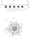
FIG. 2 is cross-sectional view of an embodiment of a belt for an elevator system; -
FIG. 3A is a cross-sectional view of an embodiment of a tension member of a belt; -
FIG. 3B is a cross-sectional view of another embodiment of a tension member of a belt; -
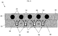
FIG. 4 is a cross-sectional view of an embodiment of an elevator belt and sheave interface at the sheave; -
FIG. 5 is a cross-sectional view of another embodiment of an elevator belt and sheave interface at the sheave; and -
FIG. 6 is a cross-sectional view of yet another embodiment of an elevator belt and sheave interface at the sheave. - A detailed description of one or more embodiments of the disclosed apparatus and method are presented herein by way of exemplification and not limitation with reference to the Figures.
- Shown in
FIG. 1 is a schematic view of an exemplarytraction elevator system 10. Features of theelevator system 10 that are not required for an understanding of the present invention (such as the guide rails, safeties, etc.) are not discussed herein. Theelevator system 10 includes anelevator car 14 operatively suspended or supported in ahoistway 12 with one ormore belts 16. The one ormore belts 16 interact withsheaves elevator system 10. Sheave 18 is configured as a diverter, deflector or idler sheave andsheave 52 is configured as atraction sheave 52, driven by amachine 50. Movement of thetraction sheave 52 by themachine 50 drives, moves and/or propels (through traction) the one ormore belts 16 that are routed around thetraction sheave 52. Diverter, deflector oridler sheaves 18 are not driven by amachine 50, but help guide the one ormore belts 16 around the various components of theelevator system 10. The one ormore belts 16 could also be connected to acounterweight 22, which is used to help balance theelevator system 10 and reduce the difference in belt tension on both sides of the traction sheave during operation. Thesheaves - In some embodiments, the
elevator system 10 could use two ormore belts 16 for suspending and/or driving theelevator car 14 In addition, theelevator system 10 could have various configurations such that either both sides of the one ormore belts 16 engage thesheaves more belts 16 engages thesheaves FIG 1 shows a 1:1 roping arrangement in which the one ormore belts 16 terminate at thecar 14 andcounterweight 22, while other embodiments may utilize other roping arrangements. - The
belts 16 are constructed to meet belt life requirements and have smooth operation, while being sufficiently strong to be capable of meeting strength requirements for suspending and/or driving theelevator car 14 andcounterweight 22. -
FIG. 2 provides a cross-sectional schematic of anexemplary belt 16 construction or design. Thebelt 16 includes a plurality oftension members 24 extending longitudinally along thebelt 16 and arranged across abelt width 26. Thetension members 24 are at least partially enclosed in ajacket material 28 to restrain movement of thetension members 24 in thebelt 16 and to protect thetension members 24. Thejacket material 28 defines atraction side 30 configured to interact with a corresponding surface of thetraction sheave 52. Exemplary materials for thejacket material 28 include the elastomers of thermoplastic and thermosetting polyurethanes, thermoplastic polyester elastomers, ethylene propylene diene elastomer, chloroprene, chlorosulfonyl polyethylene, ethylene vinyl acetate, polyamide, polypropylene, butyl rubber, acrylonitrile butadiene rubber, styrene butadiene rubber, acrylic elastomer, fluoroelastomer, silicone elastomer, polyolefin elastomer, styrene block and diene elastomer, natural rubber, or combinations thereof. Other materials may be used to form thejacket material 28 if they are adequate to meet the required functions of thebelt 16. For example, a primary function of thejacket material 28 is to provide a sufficient coefficient of friction between thebelt 16 and thetraction sheave 52 to produce a desired amount of traction therebetween. Thejacket material 28 should also transmit the traction loads to thetension members 24. In addition, thejacket material 28 should be wear resistant and protect thetension members 24 from impact damage, exposure to environmental factors, such as chemicals, for example. - The
belt 16 has abelt width 26 and abelt thickness 32, with an aspect ratio ofbelt width 26 tobelt thickness 32 greater than one. Thebelt 16 further includes aback side 34 opposite thetraction side 30 and belt edges 36 extending between thetraction side 30 and theback side 34. While fivetension members 24 are illustrated in the embodiment ofFIG. 2 , other embodiments may include other numbers oftension members 24, for example, 6, 10 or 12tension members 24. Further, while thetension members 24 of the embodiment ofFIG. 2 are substantially identical, in other embodiments, thetension members 24 may differ from one another. - Referring now to
FIG. 3A , thetension member 24 may be a plurality ofwires 38, for example,steel wires 38, which in some embodiments are formed into one ormore strands 40. In other embodiments, such as shown inFIG. 3B , thetension member 24 may include a plurality offibers 42, such as carbon fiber, glass fiber or aramid fiber, disposed in amatrix material 44. Materials such as polyurethane, vinylester, or epoxy may be utilized as the matrix material. - Referring again to
FIG. 2 , thebelt 16 includes one or more tracking features 46 at thetraction side 30. In some embodiments, such as shown inFIG. 2 , the tracking features 46 are protrusions from thetraction side 30, and may be triangular in shape as shown. It is to be appreciated, however, that while triangular-shaped tracking features are shown inFIG. 2 , other shapes such as, for example, semi-circular or trapezoidal may be utilized. Further, while in the embodiment shown the tracking features 46 are located at thetraction side 30, in other embodiments the tracking features 46 are alternatively or additionally located at theback side 34. The tracking features 46 may be formed with thejacket material 28 from the same material via, for example, an extrusion process. In other embodiments, the tracking features 46 may be formed from a material different from that of thejacket material 28 for, for example, improved wear resistance, stiffness or durability. For example, the tracking features 46 may be formed from material having a lower coefficient of friction than a coefficient of friction of thejacket material 28. The tracking features 46 may be coextruded with thejacket material 28, or may alternatively formed separately and adhered or otherwise secured to thetraction side 30. The tracking features 46 are arrayed across thebelt width 26, and are spaced apart by atracking feature gap 54, defined as a distance along thetraction side 30 between adjacent tracking features 46. In some embodiments, the tracking features 46 andtension members 24 are positioned such that the tracking features are 46 are located laterally betweenadjacent tension members 24 and over thetracking feature gaps 54, with thetension member 24 centered over its correspondingtracking feature gap 54. Further, the tracking features 46 may be evenly spaced across thebelt width 26, or in some embodiments may have unequal lateral spacing to provide improved tracking at certain portions of thebelt 16, such as nearer the lateral ends of thebelt 16. In other embodiments, thetension members 24 are located over the tracking features 46, rather than over thetracking feature gaps 54. - Referring now to
FIG. 4 , thetraction sheave 52 includescomplimentary tracking grooves 56 to receive the tracking features 46 of thebelt 16. In other embodiments, trackinggrooves 56 may be disposed at anothersheave 18 of theelevator system 10, such as a deflector and/oridler sheave 18. In the embodiment ofFIG. 4 , the trackinggrooves 56 each include a V-shapedgroove portion 58 in which the tracking features 46 are positioned. One skilled in the art will appreciate, however, that the trackinggrooves 56 may be otherwise shaped to receive tracking features 46 of shapes other than triangular. The trackinggrooves 56 each further include adebris channel 60 located at a radially inwardmost extent of the trackinggroove 56. Thedebris channel 60 is configured to collect wear debris and external debris such as deposited dust from thebelt 16, and in particular from the tracking features 46 and thetraction side 30 as they pass over thetraction sheave 52. In some embodiments thedebris channel 60 has a rectangular cross-sectional shape, but in other embodiments other cross-sectional shapes such as triangular or circular may be utilized. Referring toFIG. 1 , acleaning element 68, such as a brush, rod, finger or other element, is inserted into thedebris channel 60, at a sheave position away from thebelt 16 to remove accumulated debris from thedebris channel 60. Such debris removal - As can be seen in
FIG. 4 , the trackinggrooves 56 are laterally spaced across thetraction sheave 52 with asheave surface 62 defined between adjacent trackinggrooves 56. The sheave surfaces 62 are positioned below thetension members 24 of thebelt 16, and in some embodiments have asurface width 64 smaller than atension member width 66. Further, in some embodiments, thesurface width 64 is between ¼ and ¾ of thetension member width 66. Thesheave surface 62 may be substantially flat, or alternatively may be shaped to match an outer surface of thetension member 24. Further, in some embodiments, the trackinggrooves 46 may have a lower coefficient of friction than thesheave surface 62. This may be achieved through, for example, the use of coatings or other surface finishes. - In another embodiment, shown in
FIG. 5 , thesheave surface 62 may extend continuously under two ormore tension members 24, such as at a centermost section of thetraction sheave 52, while trackinggrooves 56 are located at an edge portion laterally outboard of the centermost section. In some embodiments,tension members 24 may be unequal in effective diameter. For example,tension members 24 located at the centermost section may have a greater effective diameter thantension members 24 located at the edge portion. - In yet another embodiment, illustrated in
FIG. 6 , laterally adjacent tracking features 46 substantially abut one another such that thebelt 16 does not include atracking feature gap 54 between the adjacent tracking features 46. Likewise, thetraction sheave 52, and/or deflector and/oridler sheave 18, includesadjacent tracking grooves 56, which substantially abut one another, such that thesheave 18/52 is absent asheave surface 62 between theadjacent tracking grooves 56. In the embodiment ofFIG. 6 , thetension members 24 are arranged such that a lateral center of eachtension member 24 is laterally offset from a lateral center of each of the tracking features 46 in abelt width 26 direction. - The arrangements disclosed herein ensure tight spacing of the
belts 16 on thetraction sheave 52 inelevator systems 10 wheremultiple belts 16 are utilized, and reduces anoverall drive sheave 52 width. Further, since thetension members 24 are well supported by the sheave surfaces 62, loading of the tracking features 46 of thebelt 16 is reduced, improving wear performance of thebelt 16 and reducing a susceptibility to belt split between thetension members 24. - The term "about" is intended to include the degree of error associated with measurement of the particular quantity based upon the equipment available at the time of filing the application. For example, "about" can include a range of ± 8% or 5%, or 2% of a given value.
- The terminology used herein is for the purpose of describing particular embodiments only and is not intended to be limiting of the present disclosure. As used herein, the singular forms "a", "an" and "the" are intended to include the plural forms as well, unless the context clearly indicates otherwise. It will be further understood that the terms "comprises" and/or "comprising," when used in this specification, specify the presence of stated features, integers, steps, operations, elements, and/or components, but do not preclude the presence or addition of one or more other features, integers, steps, operations, element components, and/or groups thereof.
- While the present disclosure has been described with reference to an exemplary embodiment or embodiments, it will be understood by those skilled in the art that various changes may be made and equivalents may be substituted for elements thereof without departing from the scope of the present disclosure. In addition, many modifications may be made to adapt a particular situation or material to the teachings of the present disclosure without departing from the essential scope thereof. Therefore, it is intended that the present disclosure not be limited to the particular embodiment disclosed as the best mode contemplated for carrying out this present disclosure, but that the present disclosure will include all embodiments falling within the scope of the claims.
Claims (13)
- A belt and sheave assembly for an elevator system, comprising:a sheave including:a plurality of tracking grooves laterally spaced across a sheave width;anda debris channel disposed in a tracking groove of the plurality of tracking grooves, defining a radially inwardmost extent of the tracking groove; anda belt including:a plurality of tension members arranged along a belt width and extending longitudinally along a length of the belt;a jacket at least partially enclosing the plurality of tension members, the jacket defining a side of the belt configured to interface with the sheave; anda plurality of tracking features extending from the side of the belt, the plurality of tracking features laterally spaced across the belt width;wherein each tracking feature is configured to be received in a tracking groove of the plurality of tracking grooves; andwherein each tension member is laterally offset from each of the tracking features of the plurality of tracking features.
- The assembly of claim 1, wherein:a sheave surface is defined between adjacent tracking grooves of the plurality of tracking grooves; anda tracking feature gap is defined between adjacent tracking features.
- The assembly of claim 2, wherein each tension member of the plurality of tension members is located over a sheave surface of the plurality of sheave surfaces.
- The assembly of claim 1, 2 or 3, wherein the debris channel is disposed radially inward of the radial extent of the corresponding tracking feature.
- The assembly of any preceding claim, wherein the tracking groove is substantially triangular in cross-sectional shape.
- The assembly of claim 5, wherein the tracking feature is substantially triangular in cross-sectional shape.
- The assembly of any preceding claim, wherein the plurality of tracking features are formed from a first material, and the jacket is formed from a second material different from the first material.
- The assembly of claim 7, wherein the first material has a lower coefficient of friction than the second material.
- The assembly of any preceding claim, wherein a tracking groove of the plurality of tracking grooves has a lower coefficient of friction than the sheave surface.
- The assembly of any preceding claim, further comprising a cleaning element insertable into the debris channel configured to remove accumulated debris from the debris channel.
- An elevator system, comprising:a hoistway;an elevator car disposed in the hoistway and movable therein; anda belt and sheave assembly as claimed in any preceding claim;wherein the belt operably connected to the elevator car to suspend and/or drive the elevator car along the hoistway.
- A sheave for an elevator system comprising:a plurality of tracking grooves laterally spaced across a sheave width; anda debris channel disposed in a tracking groove of the plurality of tracking grooves, defining a radially inwardmost extent of the tracking groove;wherein each tracking groove of the plurality of tracking grooves is configured to receive a corresponding tracking feature of a belt of an elevator system.
- The sheave of claim 12, wherein a sheave surface is defined between adjacent tracking grooves of the plurality of tracking grooves.
Applications Claiming Priority (1)
| Application Number | Priority Date | Filing Date | Title |
|---|---|---|---|
| US15/687,805 US10941021B2 (en) | 2017-08-28 | 2017-08-28 | Sheave for belt with profile tracking features |
Publications (2)
| Publication Number | Publication Date |
|---|---|
| EP3450377A1 true EP3450377A1 (en) | 2019-03-06 |
| EP3450377B1 EP3450377B1 (en) | 2023-03-08 |
Family
ID=63405113
Family Applications (1)
| Application Number | Title | Priority Date | Filing Date |
|---|---|---|---|
| EP18190835.1A Active EP3450377B1 (en) | 2017-08-28 | 2018-08-24 | Sheave for belt with profile tracking features |
Country Status (3)
| Country | Link |
|---|---|
| US (1) | US10941021B2 (en) |
| EP (1) | EP3450377B1 (en) |
| CN (1) | CN109422181A (en) |
Families Citing this family (1)
| Publication number | Priority date | Publication date | Assignee | Title |
|---|---|---|---|---|
| US11718501B2 (en) * | 2020-04-06 | 2023-08-08 | Otis Elevator Company | Elevator sheave wear detection |
Citations (8)
| Publication number | Priority date | Publication date | Assignee | Title |
|---|---|---|---|---|
| WO2006042427A1 (en) * | 2004-10-18 | 2006-04-27 | Inventio Ag | Lift comprising a flat belt as a tractive element |
| EP1777189A1 (en) * | 2005-10-21 | 2007-04-25 | Inventio Ag | Carrying means device comprising a traction sheave and carrying means as well as an elevator comprising said carrying means device |
| EP1886957A1 (en) * | 2006-08-11 | 2008-02-13 | Inventio Ag | Lift belt for a lift system and method for manufacturing such a lift belt |
| DE202008001786U1 (en) * | 2007-03-12 | 2008-12-24 | Inventio Ag | Elevator installation, suspension element for an elevator installation and device for producing a suspension element |
| US20120211310A1 (en) * | 2009-10-14 | 2012-08-23 | Danilo Peric | Elevator system and load bearing member for such a system |
| WO2013110853A1 (en) * | 2012-01-24 | 2013-08-01 | Kone Corporation | A rope of a lifting device, a rope arrangement, an elevator and a condition monitoring method for the rope of a lifting device |
| US20150101888A1 (en) * | 2013-10-10 | 2015-04-16 | Kone Corporation | Rope for a hoisting device and elevator |
| CN106081793A (en) * | 2016-07-12 | 2016-11-09 | 江南嘉捷电梯股份有限公司 | A kind of Elevator traction system |
Family Cites Families (30)
| Publication number | Priority date | Publication date | Assignee | Title |
|---|---|---|---|---|
| GB1184997A (en) | 1968-03-22 | 1970-03-18 | Gates Rubber Co | Power Transmission Belt |
| US3948113A (en) * | 1974-11-29 | 1976-04-06 | The Goodyear Tire & Rubber Company | Multi-ribbed power transmission belt and method of making said belt |
| KR890002052B1 (en) | 1983-09-21 | 1989-06-15 | 미쓰비시전기주식회사 | Traction type elevator system |
| US4840607A (en) | 1987-06-26 | 1989-06-20 | Dyneer Corporation | Pulley for poly-v belt |
| US5055090A (en) * | 1988-02-05 | 1991-10-08 | Dayco Products, Inc. | Endless power transmission belt construction and method of making the same |
| US5308291A (en) | 1992-10-16 | 1994-05-03 | Dayco Products, Inc. | Belt construction, the combination of the belt construction and a pulley and methods of making the same |
| JP2562112B2 (en) | 1993-07-07 | 1996-12-11 | 三ツ星ベルト株式会社 | V-ribbed belt and grinder wheel for V-ribbed belt |
| DK1555234T3 (en) * | 2004-01-06 | 2006-08-21 | Inventio Ag | Elevator |
| DE102005030255B4 (en) | 2005-06-29 | 2016-08-18 | Bayerische Motoren Werke Aktiengesellschaft | V-ribbed disc for a V-ribbed belt drive |
| JP4580828B2 (en) | 2005-06-30 | 2010-11-17 | 株式会社日立製作所 | Elevator equipment |
| US20070060430A1 (en) | 2005-09-09 | 2007-03-15 | Mitchell Reedy | Multiple ribbed pulley and system |
| US7882935B2 (en) * | 2005-10-21 | 2011-02-08 | Inventio Ag | Support means system with drive pulley and support means as well as elevator installation with such a support means system |
| FI20051340L (en) | 2005-12-29 | 2007-06-30 | Kone Corp | Elevator traction wheel and elevator |
| US20080116014A1 (en) * | 2006-08-11 | 2008-05-22 | Ernst Ach | Elevator installation with a belt, belt for such an elevator installation, method of producing such a belt, composite of such belts and method for assembly of such a composite in an elevator installation |
| US20080135343A1 (en) * | 2006-08-11 | 2008-06-12 | Ernst Ach | Elevator support means for an elevator system, elevator system with such an elevator support means and method for assembling such an elevator system |
| JP2008069008A (en) | 2006-08-11 | 2008-03-27 | Inventio Ag | Belt of elevator device, method of manufacturing the belt, and elevator device having the belt |
| US8057337B2 (en) * | 2009-01-20 | 2011-11-15 | The Gates Corporation | Debris ejecting sprocket and system |
| CN201567140U (en) | 2009-12-16 | 2010-09-01 | 大连恩泽电扶梯部件有限公司 | Staircase roller capable of preventing transverse motion and gap operation |
| WO2012162853A1 (en) | 2011-05-27 | 2012-12-06 | Otis Elevator Company | Sheave monitor |
| JP2013086887A (en) | 2011-10-14 | 2013-05-13 | Tsubakimoto Chain Co | Belt for moving elevator up and down |
| CN203333120U (en) | 2013-05-28 | 2013-12-11 | 日立电梯(中国)有限公司 | Elevator driving device with automatic cleaning function |
| EP2829498A1 (en) | 2013-07-26 | 2015-01-28 | Kone Corporation | Traction sheave arrangement |
| CN104930120A (en) | 2015-06-26 | 2015-09-23 | 苏州莱茵电梯制造有限公司 | Offset prevention steel belt of elevator traction machine and traction wheel applied to same |
| US11091353B2 (en) | 2015-08-21 | 2021-08-17 | Inventio Ag | Belt roller for an elevator system |
| CN205602902U (en) | 2016-02-17 | 2016-09-28 | 杭州崇沾精密机械制造有限公司 | Elevator cab wheel |
| CN205472184U (en) | 2016-02-20 | 2016-08-17 | 杭州崇沾精密机械制造有限公司 | Over -and -under type elevator driving sheave with grooving |
| CN108883902B (en) * | 2016-04-04 | 2021-05-28 | 因温特奥股份公司 | Belt and sheave arrangement with linear guidance for elevators |
| EP3243785B1 (en) * | 2016-05-11 | 2021-04-07 | KONE Corporation | Rope, elevator arrangement and elevator |
| CN105923503A (en) | 2016-06-30 | 2016-09-07 | 江南嘉捷电梯股份有限公司 | Elevator traction hanging device and elevator |
| ES2828441T3 (en) * | 2016-12-29 | 2021-05-26 | Kone Corp | Cable arrangement and lifting device |
-
2017
- 2017-08-28 US US15/687,805 patent/US10941021B2/en active Active
-
2018
- 2018-08-24 EP EP18190835.1A patent/EP3450377B1/en active Active
- 2018-08-27 CN CN201810984381.XA patent/CN109422181A/en active Pending
Patent Citations (8)
| Publication number | Priority date | Publication date | Assignee | Title |
|---|---|---|---|---|
| WO2006042427A1 (en) * | 2004-10-18 | 2006-04-27 | Inventio Ag | Lift comprising a flat belt as a tractive element |
| EP1777189A1 (en) * | 2005-10-21 | 2007-04-25 | Inventio Ag | Carrying means device comprising a traction sheave and carrying means as well as an elevator comprising said carrying means device |
| EP1886957A1 (en) * | 2006-08-11 | 2008-02-13 | Inventio Ag | Lift belt for a lift system and method for manufacturing such a lift belt |
| DE202008001786U1 (en) * | 2007-03-12 | 2008-12-24 | Inventio Ag | Elevator installation, suspension element for an elevator installation and device for producing a suspension element |
| US20120211310A1 (en) * | 2009-10-14 | 2012-08-23 | Danilo Peric | Elevator system and load bearing member for such a system |
| WO2013110853A1 (en) * | 2012-01-24 | 2013-08-01 | Kone Corporation | A rope of a lifting device, a rope arrangement, an elevator and a condition monitoring method for the rope of a lifting device |
| US20150101888A1 (en) * | 2013-10-10 | 2015-04-16 | Kone Corporation | Rope for a hoisting device and elevator |
| CN106081793A (en) * | 2016-07-12 | 2016-11-09 | 江南嘉捷电梯股份有限公司 | A kind of Elevator traction system |
Also Published As
| Publication number | Publication date |
|---|---|
| CN109422181A (en) | 2019-03-05 |
| US20190062120A1 (en) | 2019-02-28 |
| US10941021B2 (en) | 2021-03-09 |
| EP3450377B1 (en) | 2023-03-08 |
Similar Documents
| Publication | Publication Date | Title |
|---|---|---|
| CN108726321B (en) | Hybrid fiber tension member for elevator system belt | |
| AU2018202605B2 (en) | Tension member for elevator system belt | |
| US10604379B2 (en) | Elevator system belt with fabric tension member | |
| CN108726319B (en) | Tension member for elevator system belt | |
| US11274017B2 (en) | Belt with self-extinguishing layer and method of making | |
| US11078046B2 (en) | Elevator system suspension member termination with containment | |
| CN109384125B (en) | Load bearing member for a lifting system | |
| US20240262655A1 (en) | Elevator system belt | |
| EP3450378A1 (en) | Fiber belt for elevator system | |
| US20220356045A1 (en) | Elevator belt surface protection for installation | |
| EP3450377B1 (en) | Sheave for belt with profile tracking features | |
| US20070093334A1 (en) | Support Means System with Drive Pulley and Support Means as well as Elevator Installation with such a Support Means System | |
| US10926975B2 (en) | Grooved belt for elevator system | |
| US20190322488A1 (en) | Health monitoring of elevator tension member |
Legal Events
| Date | Code | Title | Description |
|---|---|---|---|
| PUAI | Public reference made under article 153(3) epc to a published international application that has entered the european phase |
Free format text: ORIGINAL CODE: 0009012 |
|
| STAA | Information on the status of an ep patent application or granted ep patent |
Free format text: STATUS: THE APPLICATION HAS BEEN PUBLISHED |
|
| AK | Designated contracting states |
Kind code of ref document: A1 Designated state(s): AL AT BE BG CH CY CZ DE DK EE ES FI FR GB GR HR HU IE IS IT LI LT LU LV MC MK MT NL NO PL PT RO RS SE SI SK SM TR |
|
| AX | Request for extension of the european patent |
Extension state: BA ME |
|
| STAA | Information on the status of an ep patent application or granted ep patent |
Free format text: STATUS: REQUEST FOR EXAMINATION WAS MADE |
|
| 17P | Request for examination filed |
Effective date: 20190905 |
|
| RBV | Designated contracting states (corrected) |
Designated state(s): AL AT BE BG CH CY CZ DE DK EE ES FI FR GB GR HR HU IE IS IT LI LT LU LV MC MK MT NL NO PL PT RO RS SE SI SK SM TR |
|
| STAA | Information on the status of an ep patent application or granted ep patent |
Free format text: STATUS: EXAMINATION IS IN PROGRESS |
|
| 17Q | First examination report despatched |
Effective date: 20201204 |
|
| GRAP | Despatch of communication of intention to grant a patent |
Free format text: ORIGINAL CODE: EPIDOSNIGR1 |
|
| STAA | Information on the status of an ep patent application or granted ep patent |
Free format text: STATUS: GRANT OF PATENT IS INTENDED |
|
| RAP3 | Party data changed (applicant data changed or rights of an application transferred) |
Owner name: OTIS ELEVATOR COMPANY |
|
| INTG | Intention to grant announced |
Effective date: 20220913 |
|
| GRAS | Grant fee paid |
Free format text: ORIGINAL CODE: EPIDOSNIGR3 |
|
| GRAA | (expected) grant |
Free format text: ORIGINAL CODE: 0009210 |
|
| STAA | Information on the status of an ep patent application or granted ep patent |
Free format text: STATUS: THE PATENT HAS BEEN GRANTED |
|
| AK | Designated contracting states |
Kind code of ref document: B1 Designated state(s): AL AT BE BG CH CY CZ DE DK EE ES FI FR GB GR HR HU IE IS IT LI LT LU LV MC MK MT NL NO PL PT RO RS SE SI SK SM TR |
|
| REG | Reference to a national code |
Ref country code: CH Ref legal event code: EP Ref country code: AT Ref legal event code: REF Ref document number: 1552471 Country of ref document: AT Kind code of ref document: T Effective date: 20230315 |
|
| REG | Reference to a national code |
Ref country code: IE Ref legal event code: FG4D |
|
| REG | Reference to a national code |
Ref country code: DE Ref legal event code: R096 Ref document number: 602018046895 Country of ref document: DE |
|
| REG | Reference to a national code |
Ref country code: LT Ref legal event code: MG9D |
|
| REG | Reference to a national code |
Ref country code: NL Ref legal event code: MP Effective date: 20230308 |
|
| PG25 | Lapsed in a contracting state [announced via postgrant information from national office to epo] |
Ref country code: RS Free format text: LAPSE BECAUSE OF FAILURE TO SUBMIT A TRANSLATION OF THE DESCRIPTION OR TO PAY THE FEE WITHIN THE PRESCRIBED TIME-LIMIT Effective date: 20230308 Ref country code: NO Free format text: LAPSE BECAUSE OF FAILURE TO SUBMIT A TRANSLATION OF THE DESCRIPTION OR TO PAY THE FEE WITHIN THE PRESCRIBED TIME-LIMIT Effective date: 20230608 Ref country code: LV Free format text: LAPSE BECAUSE OF FAILURE TO SUBMIT A TRANSLATION OF THE DESCRIPTION OR TO PAY THE FEE WITHIN THE PRESCRIBED TIME-LIMIT Effective date: 20230308 Ref country code: LT Free format text: LAPSE BECAUSE OF FAILURE TO SUBMIT A TRANSLATION OF THE DESCRIPTION OR TO PAY THE FEE WITHIN THE PRESCRIBED TIME-LIMIT Effective date: 20230308 Ref country code: HR Free format text: LAPSE BECAUSE OF FAILURE TO SUBMIT A TRANSLATION OF THE DESCRIPTION OR TO PAY THE FEE WITHIN THE PRESCRIBED TIME-LIMIT Effective date: 20230308 Ref country code: ES Free format text: LAPSE BECAUSE OF FAILURE TO SUBMIT A TRANSLATION OF THE DESCRIPTION OR TO PAY THE FEE WITHIN THE PRESCRIBED TIME-LIMIT Effective date: 20230308 |
|
| REG | Reference to a national code |
Ref country code: AT Ref legal event code: MK05 Ref document number: 1552471 Country of ref document: AT Kind code of ref document: T Effective date: 20230308 |
|
| PG25 | Lapsed in a contracting state [announced via postgrant information from national office to epo] |
Ref country code: SE Free format text: LAPSE BECAUSE OF FAILURE TO SUBMIT A TRANSLATION OF THE DESCRIPTION OR TO PAY THE FEE WITHIN THE PRESCRIBED TIME-LIMIT Effective date: 20230308 Ref country code: NL Free format text: LAPSE BECAUSE OF FAILURE TO SUBMIT A TRANSLATION OF THE DESCRIPTION OR TO PAY THE FEE WITHIN THE PRESCRIBED TIME-LIMIT Effective date: 20230308 Ref country code: GR Free format text: LAPSE BECAUSE OF FAILURE TO SUBMIT A TRANSLATION OF THE DESCRIPTION OR TO PAY THE FEE WITHIN THE PRESCRIBED TIME-LIMIT Effective date: 20230609 Ref country code: FI Free format text: LAPSE BECAUSE OF FAILURE TO SUBMIT A TRANSLATION OF THE DESCRIPTION OR TO PAY THE FEE WITHIN THE PRESCRIBED TIME-LIMIT Effective date: 20230308 |
|
| PG25 | Lapsed in a contracting state [announced via postgrant information from national office to epo] |
Ref country code: SM Free format text: LAPSE BECAUSE OF FAILURE TO SUBMIT A TRANSLATION OF THE DESCRIPTION OR TO PAY THE FEE WITHIN THE PRESCRIBED TIME-LIMIT Effective date: 20230308 Ref country code: RO Free format text: LAPSE BECAUSE OF FAILURE TO SUBMIT A TRANSLATION OF THE DESCRIPTION OR TO PAY THE FEE WITHIN THE PRESCRIBED TIME-LIMIT Effective date: 20230308 Ref country code: PT Free format text: LAPSE BECAUSE OF FAILURE TO SUBMIT A TRANSLATION OF THE DESCRIPTION OR TO PAY THE FEE WITHIN THE PRESCRIBED TIME-LIMIT Effective date: 20230710 Ref country code: EE Free format text: LAPSE BECAUSE OF FAILURE TO SUBMIT A TRANSLATION OF THE DESCRIPTION OR TO PAY THE FEE WITHIN THE PRESCRIBED TIME-LIMIT Effective date: 20230308 Ref country code: CZ Free format text: LAPSE BECAUSE OF FAILURE TO SUBMIT A TRANSLATION OF THE DESCRIPTION OR TO PAY THE FEE WITHIN THE PRESCRIBED TIME-LIMIT Effective date: 20230308 Ref country code: AT Free format text: LAPSE BECAUSE OF FAILURE TO SUBMIT A TRANSLATION OF THE DESCRIPTION OR TO PAY THE FEE WITHIN THE PRESCRIBED TIME-LIMIT Effective date: 20230308 |
|
| PG25 | Lapsed in a contracting state [announced via postgrant information from national office to epo] |
Ref country code: SK Free format text: LAPSE BECAUSE OF FAILURE TO SUBMIT A TRANSLATION OF THE DESCRIPTION OR TO PAY THE FEE WITHIN THE PRESCRIBED TIME-LIMIT Effective date: 20230308 Ref country code: PL Free format text: LAPSE BECAUSE OF FAILURE TO SUBMIT A TRANSLATION OF THE DESCRIPTION OR TO PAY THE FEE WITHIN THE PRESCRIBED TIME-LIMIT Effective date: 20230308 Ref country code: IS Free format text: LAPSE BECAUSE OF FAILURE TO SUBMIT A TRANSLATION OF THE DESCRIPTION OR TO PAY THE FEE WITHIN THE PRESCRIBED TIME-LIMIT Effective date: 20230708 |
|
| REG | Reference to a national code |
Ref country code: DE Ref legal event code: R097 Ref document number: 602018046895 Country of ref document: DE |
|
| PLBE | No opposition filed within time limit |
Free format text: ORIGINAL CODE: 0009261 |
|
| STAA | Information on the status of an ep patent application or granted ep patent |
Free format text: STATUS: NO OPPOSITION FILED WITHIN TIME LIMIT |
|
| PG25 | Lapsed in a contracting state [announced via postgrant information from national office to epo] |
Ref country code: SI Free format text: LAPSE BECAUSE OF FAILURE TO SUBMIT A TRANSLATION OF THE DESCRIPTION OR TO PAY THE FEE WITHIN THE PRESCRIBED TIME-LIMIT Effective date: 20230308 Ref country code: DK Free format text: LAPSE BECAUSE OF FAILURE TO SUBMIT A TRANSLATION OF THE DESCRIPTION OR TO PAY THE FEE WITHIN THE PRESCRIBED TIME-LIMIT Effective date: 20230308 |
|
| 26N | No opposition filed |
Effective date: 20231211 |
|
| PG25 | Lapsed in a contracting state [announced via postgrant information from national office to epo] |
Ref country code: MC Free format text: LAPSE BECAUSE OF FAILURE TO SUBMIT A TRANSLATION OF THE DESCRIPTION OR TO PAY THE FEE WITHIN THE PRESCRIBED TIME-LIMIT Effective date: 20230308 |
|
| REG | Reference to a national code |
Ref country code: CH Ref legal event code: PL |
|
| PG25 | Lapsed in a contracting state [announced via postgrant information from national office to epo] |
Ref country code: MC Free format text: LAPSE BECAUSE OF FAILURE TO SUBMIT A TRANSLATION OF THE DESCRIPTION OR TO PAY THE FEE WITHIN THE PRESCRIBED TIME-LIMIT Effective date: 20230308 |
|
| PG25 | Lapsed in a contracting state [announced via postgrant information from national office to epo] |
Ref country code: LU Free format text: LAPSE BECAUSE OF NON-PAYMENT OF DUE FEES Effective date: 20230824 |
|
| GBPC | Gb: european patent ceased through non-payment of renewal fee |
Effective date: 20230824 |
|
| PG25 | Lapsed in a contracting state [announced via postgrant information from national office to epo] |
Ref country code: LU Free format text: LAPSE BECAUSE OF NON-PAYMENT OF DUE FEES Effective date: 20230824 Ref country code: CH Free format text: LAPSE BECAUSE OF NON-PAYMENT OF DUE FEES Effective date: 20230831 |
|
| REG | Reference to a national code |
Ref country code: BE Ref legal event code: MM Effective date: 20230831 |
|
| REG | Reference to a national code |
Ref country code: IE Ref legal event code: MM4A |
|
| PG25 | Lapsed in a contracting state [announced via postgrant information from national office to epo] |
Ref country code: IT Free format text: LAPSE BECAUSE OF FAILURE TO SUBMIT A TRANSLATION OF THE DESCRIPTION OR TO PAY THE FEE WITHIN THE PRESCRIBED TIME-LIMIT Effective date: 20230308 |
|
| PG25 | Lapsed in a contracting state [announced via postgrant information from national office to epo] |
Ref country code: IE Free format text: LAPSE BECAUSE OF NON-PAYMENT OF DUE FEES Effective date: 20230824 |
|
| PG25 | Lapsed in a contracting state [announced via postgrant information from national office to epo] |
Ref country code: GB Free format text: LAPSE BECAUSE OF NON-PAYMENT OF DUE FEES Effective date: 20230824 |
|
| PG25 | Lapsed in a contracting state [announced via postgrant information from national office to epo] |
Ref country code: IE Free format text: LAPSE BECAUSE OF NON-PAYMENT OF DUE FEES Effective date: 20230824 Ref country code: GB Free format text: LAPSE BECAUSE OF NON-PAYMENT OF DUE FEES Effective date: 20230824 |
|
| PG25 | Lapsed in a contracting state [announced via postgrant information from national office to epo] |
Ref country code: BE Free format text: LAPSE BECAUSE OF NON-PAYMENT OF DUE FEES Effective date: 20230831 |
|
| PG25 | Lapsed in a contracting state [announced via postgrant information from national office to epo] |
Ref country code: BG Free format text: LAPSE BECAUSE OF FAILURE TO SUBMIT A TRANSLATION OF THE DESCRIPTION OR TO PAY THE FEE WITHIN THE PRESCRIBED TIME-LIMIT Effective date: 20230308 |
|
| PG25 | Lapsed in a contracting state [announced via postgrant information from national office to epo] |
Ref country code: BG Free format text: LAPSE BECAUSE OF FAILURE TO SUBMIT A TRANSLATION OF THE DESCRIPTION OR TO PAY THE FEE WITHIN THE PRESCRIBED TIME-LIMIT Effective date: 20230308 |
|
| PG25 | Lapsed in a contracting state [announced via postgrant information from national office to epo] |
Ref country code: CY Free format text: LAPSE BECAUSE OF FAILURE TO SUBMIT A TRANSLATION OF THE DESCRIPTION OR TO PAY THE FEE WITHIN THE PRESCRIBED TIME-LIMIT; INVALID AB INITIO Effective date: 20180824 |
|
| PG25 | Lapsed in a contracting state [announced via postgrant information from national office to epo] |
Ref country code: HU Free format text: LAPSE BECAUSE OF FAILURE TO SUBMIT A TRANSLATION OF THE DESCRIPTION OR TO PAY THE FEE WITHIN THE PRESCRIBED TIME-LIMIT; INVALID AB INITIO Effective date: 20180824 |
|
| PGFP | Annual fee paid to national office [announced via postgrant information from national office to epo] |
Ref country code: DE Payment date: 20250724 Year of fee payment: 8 |
|
| PGFP | Annual fee paid to national office [announced via postgrant information from national office to epo] |
Ref country code: FR Payment date: 20250723 Year of fee payment: 8 |
|
| PG25 | Lapsed in a contracting state [announced via postgrant information from national office to epo] |
Ref country code: TR Free format text: LAPSE BECAUSE OF FAILURE TO SUBMIT A TRANSLATION OF THE DESCRIPTION OR TO PAY THE FEE WITHIN THE PRESCRIBED TIME-LIMIT Effective date: 20230308 |