EP3450338A1 - Device for applying labels for machine tools - Google Patents
Device for applying labels for machine tools Download PDFInfo
- Publication number
- EP3450338A1 EP3450338A1 EP18189654.9A EP18189654A EP3450338A1 EP 3450338 A1 EP3450338 A1 EP 3450338A1 EP 18189654 A EP18189654 A EP 18189654A EP 3450338 A1 EP3450338 A1 EP 3450338A1
- Authority
- EP
- European Patent Office
- Prior art keywords
- passage
- opening
- applying labels
- main body
- rotor
- Prior art date
- Legal status (The legal status is an assumption and is not a legal conclusion. Google has not performed a legal analysis and makes no representation as to the accuracy of the status listed.)
- Granted
Links
Images




Classifications
-
- B—PERFORMING OPERATIONS; TRANSPORTING
- B65—CONVEYING; PACKING; STORING; HANDLING THIN OR FILAMENTARY MATERIAL
- B65C—LABELLING OR TAGGING MACHINES, APPARATUS, OR PROCESSES
- B65C9/00—Details of labelling machines or apparatus
- B65C9/26—Devices for applying labels
- B65C9/36—Wipers; Pressers
-
- B—PERFORMING OPERATIONS; TRANSPORTING
- B65—CONVEYING; PACKING; STORING; HANDLING THIN OR FILAMENTARY MATERIAL
- B65C—LABELLING OR TAGGING MACHINES, APPARATUS, OR PROCESSES
- B65C9/00—Details of labelling machines or apparatus
- B65C9/0015—Preparing the labels or articles, e.g. smoothing, removing air bubbles
-
- B—PERFORMING OPERATIONS; TRANSPORTING
- B65—CONVEYING; PACKING; STORING; HANDLING THIN OR FILAMENTARY MATERIAL
- B65C—LABELLING OR TAGGING MACHINES, APPARATUS, OR PROCESSES
- B65C9/00—Details of labelling machines or apparatus
- B65C9/0015—Preparing the labels or articles, e.g. smoothing, removing air bubbles
- B65C2009/0059—Preparing the articles
Definitions
- This invention relates to a device for applying labels, for machine tools.
- the invention relates to a device for applying labels, for machine tools for the machining of panels made of wood or other material.
- the device can be advantageously applied in combination with machine tools comprising a work surface on which the panels to be machined are positioned, at least one operating head movable above the work surface in such a way as to carry out on the panel, automatically, a predetermined sequence of mechanical machining operations which comprise, in particular, the cutting of the panels in such a way as to obtain from them a predetermined number of workpieces of, obviously, smaller dimensions, which, in turn, must normally be identified by means of the relative application of labels before the subsequent operations.
- machine tools comprising a work surface on which the panels to be machined are positioned, at least one operating head movable above the work surface in such a way as to carry out on the panel, automatically, a predetermined sequence of mechanical machining operations which comprise, in particular, the cutting of the panels in such a way as to obtain from them a predetermined number of workpieces of, obviously, smaller dimensions, which, in turn, must normally be identified by means of the relative application of labels before the subsequent operations.
- machine tools equipped with a printer for generating labels, mounted on an operating head movable above the work surface, for generating and applying labels on the workpieces being machined, moving above the latter.
- machine tools equipped with a printer for generating labels, mounted in a fixed fashion on the machine itself, and a device integral with the operating head movable above the working surface, for picking up the label from the printer and applying it on the piece to be identified.
- This movable device is normally connected to a system for generating a vacuum, to allow the label to be retained until the relative application on the piece, and also an external system for generating compressed air for cleaning the piece before applying the label.
- the aim of the invention is therefore to provide a device for applying labels for machine tools which is multi-purpose.
- Another aim of the invention is to provide a device for applying labels for machine tools which allows labels of different shapes and sizes to be applied.
- a further aim of the invention is to provide a device for applying labels for machine tools which is efficient and reliable to use.
- Another aim of the invention is to provide a device for applying labels for machine tools which is easy to use.
- Another aim of the invention is to provide a device for applying labels for machine tools which is able to offer a high level of flexibility in use.
- a further aim of the invention is to provide a device for applying labels for machine tools which uses as much as possible, for its operation, the sources of energy with which the operating heads of machine tools are normally provided.
- a specific object of this invention is therefore a device for applying labels on panels or other workpieces configured for being mounted in an operating head of a machine tool, equipped with a rotatable gripping element, said device for applying labels comprising: a movable body comprising coupling means for the coupling, in use, to said rotatable gripping element and a rotor; a main body in which is formed a cavity in which is housed said rotor, said cavity being in communication with at least one expelling member for expelling air and, through a first passage, with an opening open towards the exterior of said main body; and a first pressure reducing element connected to said main body and in communication with said first passage at a zone between said rotor and said opening; wherein said rotor is configured in such a way that, when it is rotated, it draws air from said first passage, allowing the picking up and retaining of a label at said opening, and expels air from said at least one expelling member allowing, in use, the cleaning of a panel or another
- said rotor may be a rotor with an axial inlet flow and a radial outlet flow.
- said opening is formed in a base zone of said main body.
- said device for applying labels may comprise a positioning element for allowing, in use, the positioning of said main body with respect to said operating head.
- a second passage communicating with said opening for placing, in use, said opening in communication with a pressure sensor for measuring the pressure in said opening, in such a way as to check, on the basis of the pressure measured, the presence of a label at said opening.
- said device for applying labels may comprise a second pressure reducing element connected to said main body and communicating with said rotor and with the exterior of said device for applying labels in such a way as to allow the escape of air from said main body when said rotor is rotating and said at least one expelling member is closed.
- a specific object of this invention is also a device for applying labels on panels or other workpieces configured for being mounted in an operating head of a machine tool, equipped with a compressed air system, said device for applying labels comprising: coupling means for coupling, in use, said device for applying labels to said operating head; and a main body in which is formed a first passage which opens to the exterior of said main body though a connecting element for the connection to said compressed air system and through at least one expelling member for expelling air, in said first passage there being a Venturi meter, in said main body being formed a second passage communicating with an opening formed in said main body and open towards the exterior of said main body and with a zone of said first passage located upstream of said Venturi meter, in such a way that when, in use, compressed air is introduced in said first passage through said compressed air system, a flow of air escapes from said at least one expelling member for cleaning a panel or another piece and a negative pressure is generated, in said second passage, such as to allow said device for applying labels to pick
- said opening is provided in a base zone of said main body.
- a third passage communicating with said opening for placing, in use, said opening in communication with a pressure sensor for measuring the pressure in said opening, in such a way as to check, on the basis of the pressure measured, the presence of a label at said opening.
- At least an end stretch of said third passage may comprise an annular passage positioned around at least an end stretch of said first passage.
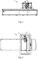
- the numeral 1 denotes a machine tool for cutting panels.
- a printer 2' for printing labels and an operating head 2 on which can be mounted various types of machine tools and devices of other types, also including the devices for the application of labels described below.
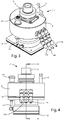
- FIG. 3-8 A first example of a device for applying labels 3 according to the invention is shown in Figures 3-8 .
- the device for applying labels 3 comprises an outer body 4 internally hollow, in which is housed a rotor 5 with axial inlet flow and radial outlet flow.
- the hub of the rotor 5 is rigidly connected to the lower end of a coupling element 6, which is in turn connected, in a rotatable fashion, to the upper part of the outer body 4 by means of bearings 7.
- the coupling element 6 has, in the relative upper part, a portion in the shape of a truncated cone so as to be able to couple to the spindle of the operating head 2, so that the rotation of the spindle rotates the coupling element 6 and the relative rotor 5.
- the coupling element 6 and the rotor 5 are therefore part of a single movable body 6' rotatable relative to the outer body 4.
- a positioning pin 8 designed to engage in a corresponding cavity made in the operating head 2, to allow the positioning of the outer body 4 with respect to the operating head 2.
- the device for applying labels 3 there may be, between the latter and the operating head 2, and intermediate element provided with one or more cavities for the housing of the positioning pin 8 and configured in such a way as to be able to adopt various angular positions with respect to the operating head 2.
- an axial passage 9 is formed which extends from the zone in which is housed the rotor 5 up to a lower chamber 10 made in the lower part of the above-mentioned outer body 4, beneath the rotor 5, and leading to the exterior through an opening 11, around which there is a seal 12.
- first radial passage 13 which puts in communication the rotor 5 with three directional nozzles 14a, 14b, 14c, that is, three expelling members with a variable configuration, positioned one alongside the other.
- a second radial passage 15 which intercepts the axial passage 9 at a zone between the rotor 5 and the lower chamber 10, leading to the exterior through a first filter 16 which performs the function of reducing the air pressure when this passes through the first filter 16 from the exterior to the interior of the outer body 4.
- a third passage 17 which places in communication the rotor 5 with the exterior through an opening where a second filter 18 is installed having the purpose of allowing the escape of the radial flow of air produced by the rotation of the rotor 5 in the case of simultaneous blockage of the directional nozzles 14a, 14b, 14c.
- a conduit 19 with the relative ends communicating with the lower chamber 10 and a connector 20 for the connection to a vacuum meter (not illustrated) for checking the pressure in the lower chamber 10.
- the vacuum meter performs a control function for checking any presence of a label on the bottom of the outer body 4 by measuring the pressure existing in the lower chamber 10.
- the operating head 2 picks up the device for applying labels 3, normally housed in a tool store, in such a way that the relative spindle couples with the coupling element 6 and the positioning pin 8 inserts in the corresponding cavity of the operating head 2, and the connector 20 connects to an outlet end (not illustrated) of the compressed air system of the tool machine 1.
- the rotations of the rotor 5 determines an axial flow of entering air in the underlying axial passage 9 and, simultaneously, a radial flow of exiting air from the rotor 5 and, therefore, from the directional nozzles 14a, 14b, 14c.
- the device for applying labels 3 approaches the label produced by the above-mentioned printer 2', the label is picked up by the lower part of the outer body 4 thanks to the negative pressure which is created in the axial passage 9 and in the lower chamber 10 by the effect of the rotation of the rotor 5.
- the retaining of the label picked up on the bottom of the outer body 4 during the rotation of the rotor 5 is made possible thanks to the first filter 16 which allows the device for applying labels 3 to draw air from the exterior to its interior, reducing the pressure and therefore generating a negative pressure condition in the lower chamber 10 such as to attract the label towards the outer body 4.
- the operating head 2 with the device for applying labels 3 moves above the panel or portion of panel to be identified, in this way allowing the cleaning of the upper surface of the panel, through the flow of air exiting from the directional nozzles 14a, 14b, 14c, before lowering onto the panel so that the underlying adhesive part of the label adheres on the surface of the piece previously cleaned.
- the operating head 2 and the device for applying labels 3 operate according to the same methods described above.
- the numeral 21 denotes a second device for applying labels according to the invention.
- the device for applying labels 21 comprises an outer body 22 internally hollow, from the upper part of which protrudes upwards a coupling element 23 with a truncated cone shaped end part configured for coupling with the spindle of the operating head 2 of the machine tool 1.
- a positioning pin 24 shaped in such a way as to be able to be inserted in a corresponding cavity made in the operating head 2 when the coupling element 23 couples with the relative spindle.
- the operating head 2 there can be several cavities made along a circular trajectory and sized in such a way as to each be able to receive the positioning pin 24.
- the device for applying labels 21 there may be, between the latter and the operating head 2, and intermediate element provided with one or more cavities for the housing of the positioning pin 24 and configured in such a way as to be able to adopt various angular positions with respect to the operating head 2.
- a vertical passage 25 which leads, above, through a first connector 26 for the connection to the compressed air system of the machine tool 1 and, below, through a directional nozzle 27 with a variable configuration with an outlet opening 28 to the relative end.
- Venturi tube or Venturi meter 29 In the vertical passage 25 there is also a Venturi tube or Venturi meter 29.
- a second passage 30 consisting of a first horizontal section 31 and a second vertical section 32 leading to a lower chamber 33 formed on the lower part of the outer body 22 and communicating with the exterior through an opening 34, around which there is a seal 35.
- the vacuum meter performs a control function for checking any presence of a label on the bottom of the outer body 22 by measuring the pressure existing in the lower chamber 33.
- the spindle of the operating head 2 grips the coupling element 23 of the device for applying labels 21.
- the first connector 26 engages with a corresponding connecting element of the compressed air system of the machine tool 1, whilst the second connector 37, if present together with the relative third passage 36, connects with the above-mentioned vacuum meter.
- the compressed air passes through the Venturi tube 29, generating, in this way, a flow of air under pressure exiting from the outlet opening 28 and a negative pressure upstream of the Venturi tube 29.
- the flow of air exiting from the outlet opening 28 cleans away, before applying the label, any dust and impurities present on the zone of the underlying panel which is to receive the label.
- the negative pressure which is created in the zone upstream of the Venturi tube 29 propagates, that is, extends, along the entire second passage 30 up to the lower chamber 33, allowing, in this way, the device for applying labels 21 to pick up, at the seal 35, the label generated by the above-mentioned printer 2' thanks to the suction action of the negative pressure present in the lower chamber 33.
- the operating head 2 with the relative device for applying labels 21 moves above the panel to be identified, cleaned previously by the flow of air exiting from the directional nozzle 27, and then lowers on the panel until resting on it the lower adhesive surface of the label, which, in this way, will remain attached to the panel.
- the numeral 38 denotes a device for applying labels according to a third embodiment of the invention.
- the device for applying labels 38 comprises an outer body 39 internally hollow, from the upper part of which protrudes upwards a coupling element 40 with a truncated cone shaped end part configured for coupling with the spindle of the operating head 2 of the machine tool 1.
- a positioning pin 41 shaped in such a way as to be able to be inserted in a corresponding cavity made in the operating head 2 when the coupling element 40 couples with the relative spindle.
- the operating head 2 there can be several cavities made along a circular trajectory and sized in such a way as to each be able to receive the positioning pin 41.
- a vertical passage 42 which leads, above, through a first connector 43 for the connection to the compressed air system of the machine tool 1 and, below, through a directional nozzle 44 with a variable configuration with an outlet opening 45 to the relative end.
- Venturi tube or Venturi meter 46 In the vertical passage 42 there is also a Venturi tube or Venturi meter 46.
- the vertical passage 42 Upstream of the Venturi tube 46, that is, between the connector 43 and the Venturi tube 46, the vertical passage 42 is intercepted by a second passage 47 consisting of a first horizontal section 48 and a second vertical section 49 leading to a lower chamber 50 formed on the lower part of the outer body 39 and communicating with the exterior through an opening 51, around which there is a seal 52.
- the annular passage 54 may in turn be connected to a vacuum meter (not illustrated) for checking the pressure in the lower chamber 50.
- the vacuum meter performs a control function for checking any presence of a label on the bottom of the outer body 39 by measuring the pressure existing in the lower chamber 50.
- the operation of the device for applying labels 38 is identical to that of the device for applying labels 21 described above.
- the devices for applying labels described above are therefore configured in such a way as to allow the application, in an economic and efficient manner, of any type of adhesive label on panels or portions of panels, using in the best possible manner the resources normally present in the machine tools in which these devices are designed to be mounted.
Landscapes
- Labeling Devices (AREA)
Abstract
Description
- This invention relates to a device for applying labels, for machine tools.
- More specifically, the invention relates to a device for applying labels, for machine tools for the machining of panels made of wood or other material.
- In particular, the device can be advantageously applied in combination with machine tools comprising a work surface on which the panels to be machined are positioned, at least one operating head movable above the work surface in such a way as to carry out on the panel, automatically, a predetermined sequence of mechanical machining operations which comprise, in particular, the cutting of the panels in such a way as to obtain from them a predetermined number of workpieces of, obviously, smaller dimensions, which, in turn, must normally be identified by means of the relative application of labels before the subsequent operations.
- The following description will be aimed at a device for applying labels mounted on a machine tool for cutting wooden panels, but it is clear that it must not be considered to be limited to this specific use.
- There are various prior art devices for the application of labels for use in machine tools.
- There are, in fact, machine tools equipped with a printer for generating labels, mounted on an operating head movable above the work surface, for generating and applying labels on the workpieces being machined, moving above the latter.
- There are also machine tools equipped with a printer for generating labels, mounted in a fixed fashion on the machine itself, and a device integral with the operating head movable above the working surface, for picking up the label from the printer and applying it on the piece to be identified.
- This movable device is normally connected to a system for generating a vacuum, to allow the label to be retained until the relative application on the piece, and also an external system for generating compressed air for cleaning the piece before applying the label.
- In light of the above, the aim of the invention is therefore to provide a device for applying labels for machine tools which is multi-purpose.
- Another aim of the invention is to provide a device for applying labels for machine tools which allows labels of different shapes and sizes to be applied.
- A further aim of the invention is to provide a device for applying labels for machine tools which is efficient and reliable to use.
- Another aim of the invention is to provide a device for applying labels for machine tools which is easy to use.
- Another aim of the invention is to provide a device for applying labels for machine tools which is able to offer a high level of flexibility in use.
- A further aim of the invention is to provide a device for applying labels for machine tools which uses as much as possible, for its operation, the sources of energy with which the operating heads of machine tools are normally provided.
- A specific object of this invention is therefore a device for applying labels on panels or other workpieces configured for being mounted in an operating head of a machine tool, equipped with a rotatable gripping element, said device for applying labels comprising: a movable body comprising coupling means for the coupling, in use, to said rotatable gripping element and a rotor; a main body in which is formed a cavity in which is housed said rotor, said cavity being in communication with at least one expelling member for expelling air and, through a first passage, with an opening open towards the exterior of said main body; and a first pressure reducing element connected to said main body and in communication with said first passage at a zone between said rotor and said opening; wherein said rotor is configured in such a way that, when it is rotated, it draws air from said first passage, allowing the picking up and retaining of a label at said opening, and expels air from said at least one expelling member allowing, in use, the cleaning of a panel or another piece which is to receive said label.
- Advantageously, according to the invention, said rotor may be a rotor with an axial inlet flow and a radial outlet flow.
- Preferably, according to this invention, said opening is formed in a base zone of said main body.
- Further, according to the invention, said device for applying labels may comprise a positioning element for allowing, in use, the positioning of said main body with respect to said operating head.
- Optionally, according to the invention, in said main body there may be formed a second passage communicating with said opening for placing, in use, said opening in communication with a pressure sensor for measuring the pressure in said opening, in such a way as to check, on the basis of the pressure measured, the presence of a label at said opening.
- Further, according to the invention, said device for applying labels may comprise a second pressure reducing element connected to said main body and communicating with said rotor and with the exterior of said device for applying labels in such a way as to allow the escape of air from said main body when said rotor is rotating and said at least one expelling member is closed.
- A specific object of this invention is also a device for applying labels on panels or other workpieces configured for being mounted in an operating head of a machine tool, equipped with a compressed air system, said device for applying labels comprising: coupling means for coupling, in use, said device for applying labels to said operating head; and a main body in which is formed a first passage which opens to the exterior of said main body though a connecting element for the connection to said compressed air system and through at least one expelling member for expelling air, in said first passage there being a Venturi meter, in said main body being formed a second passage communicating with an opening formed in said main body and open towards the exterior of said main body and with a zone of said first passage located upstream of said Venturi meter, in such a way that when, in use, compressed air is introduced in said first passage through said compressed air system, a flow of air escapes from said at least one expelling member for cleaning a panel or another piece and a negative pressure is generated, in said second passage, such as to allow said device for applying labels to pick up and retain a label at said opening.
- Preferably, according to this invention, said opening is provided in a base zone of said main body.
- Optionally, according to the invention, in said main body there may be formed a third passage communicating with said opening for placing, in use, said opening in communication with a pressure sensor for measuring the pressure in said opening, in such a way as to check, on the basis of the pressure measured, the presence of a label at said opening.
- Further, according to the invention, at least an end stretch of said third passage may comprise an annular passage positioned around at least an end stretch of said first passage.
- The present invention is now described, by way of example and without limiting the scope of the invention, with reference to the accompanying drawings which illustrate preferred embodiments of it, in which:
-
Figure 1 is a side view of a machine tool on which there is an operating head movable above the relative work surface, on which it is possible to automatically attach a device for applying labels for machine tools according to the invention; -
Figure 2 is a top plan view of the machine tool ofFigure 1 ; -
Figure 3 is an axonometric view of a device for applying labels for machine tools according to a first embodiment of the invention; -
Figure 4 is a side view of the device ofFigure 3 ; -
Figure 5 is a cross section view through the line H-H ofFigure 4 ; -
Figure 6 is a further side view of the device ofFigure 3 ; -
Figure 7 is a cross section view through the line G-G ofFigure 6 ; -
Figure 8 is a cutaway view of the device ofFigure 3 ; -
Figure 9 is an axonometric view of a device for applying labels for machine tools according to a second embodiment of the invention; -
Figure 10 is a side view of the device ofFigure 9 , also showing, with dashed lines, hidden internal parts; -
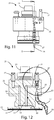
Figure 11 is a further side view of the device ofFigure 9 ; -
Figure 12 is a cross section view through the line B-B ofFigure 11 ; -
Figure 13 is a view of a detail ofFigure 12 ; -
Figure 14 is an axonometric view of a device for applying labels for machine tools according to a third embodiment of the invention; -
Figure 15 is a side view of the device ofFigure 14 ; -
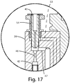
Figure 16 is a cross section view through the line C-C ofFigure 15 ; and -
Figure 17 is a view of a detail ofFigure 16 . - Similar parts will be indicated in the various drawing with the same reference numerals.
- With reference to
Figures 1 and 2 , thenumeral 1 denotes a machine tool for cutting panels. - In the
machine tool 1 there is a printer 2' for printing labels and anoperating head 2, on which can be mounted various types of machine tools and devices of other types, also including the devices for the application of labels described below. - A first example of a device for applying
labels 3 according to the invention is shown inFigures 3-8 . - The device for applying
labels 3 comprises anouter body 4 internally hollow, in which is housed arotor 5 with axial inlet flow and radial outlet flow. - The hub of the
rotor 5 is rigidly connected to the lower end of acoupling element 6, which is in turn connected, in a rotatable fashion, to the upper part of theouter body 4 by means ofbearings 7. - The
coupling element 6 has, in the relative upper part, a portion in the shape of a truncated cone so as to be able to couple to the spindle of theoperating head 2, so that the rotation of the spindle rotates thecoupling element 6 and therelative rotor 5. - The
coupling element 6 and therotor 5 are therefore part of a single movable body 6' rotatable relative to theouter body 4. - From the upper part of the
outer body 4 extends, upwards, apositioning pin 8 designed to engage in a corresponding cavity made in theoperating head 2, to allow the positioning of theouter body 4 with respect to theoperating head 2. - On the
operating head 2 there can be several cavities made along a circular trajectory and sized in such a way as to each be able to receive the above-mentionedpositioning pin 8. - The provision of these cavities for housing the
positioning pin 8 allows the variation, during assembly, of the orientation of the device for applyinglabels 3 and therefore also the orientation of the labels to be applied on the underlying panel. - Alternatively, according to a variant of the invention, in order to allow the variation of the orientation of the device for applying
labels 3, there may be, between the latter and theoperating head 2, and intermediate element provided with one or more cavities for the housing of thepositioning pin 8 and configured in such a way as to be able to adopt various angular positions with respect to theoperating head 2. - Inside the
outer body 4 anaxial passage 9 is formed which extends from the zone in which is housed therotor 5 up to alower chamber 10 made in the lower part of the above-mentionedouter body 4, beneath therotor 5, and leading to the exterior through anopening 11, around which there is aseal 12. - In the
outer body 4 is also made a firstradial passage 13 which puts in communication therotor 5 with threedirectional nozzles - In the
outer body 4 is also formed a secondradial passage 15 which intercepts theaxial passage 9 at a zone between therotor 5 and thelower chamber 10, leading to the exterior through afirst filter 16 which performs the function of reducing the air pressure when this passes through thefirst filter 16 from the exterior to the interior of theouter body 4. - Optionally, there may also be a
third passage 17 which places in communication therotor 5 with the exterior through an opening where asecond filter 18 is installed having the purpose of allowing the escape of the radial flow of air produced by the rotation of therotor 5 in the case of simultaneous blockage of thedirectional nozzles - Again optionally, in the device for applying
labels 3 there may also be aconduit 19 with the relative ends communicating with thelower chamber 10 and aconnector 20 for the connection to a vacuum meter (not illustrated) for checking the pressure in thelower chamber 10. - The vacuum meter performs a control function for checking any presence of a label on the bottom of the
outer body 4 by measuring the pressure existing in thelower chamber 10. - When the
machine tool 1 requires the application of labels to the panels being machined, theoperating head 2 picks up the device for applyinglabels 3, normally housed in a tool store, in such a way that the relative spindle couples with thecoupling element 6 and thepositioning pin 8 inserts in the corresponding cavity of theoperating head 2, and theconnector 20 connects to an outlet end (not illustrated) of the compressed air system of thetool machine 1. - After performing the coupling between the
coupling element 6 and the spindle of theoperating head 2, the latter is put into operation, thus rotating also thecoupling element 6 and therelative rotor 5. - The rotations of the
rotor 5 determines an axial flow of entering air in the underlyingaxial passage 9 and, simultaneously, a radial flow of exiting air from therotor 5 and, therefore, from thedirectional nozzles - Therefore, when the device for applying
labels 3 approaches the label produced by the above-mentioned printer 2', the label is picked up by the lower part of theouter body 4 thanks to the negative pressure which is created in theaxial passage 9 and in thelower chamber 10 by the effect of the rotation of therotor 5. - The retaining of the label picked up on the bottom of the
outer body 4 during the rotation of therotor 5 is made possible thanks to thefirst filter 16 which allows the device for applyinglabels 3 to draw air from the exterior to its interior, reducing the pressure and therefore generating a negative pressure condition in thelower chamber 10 such as to attract the label towards theouter body 4. - After having picked up the label, the operating
head 2 with the device for applyinglabels 3 moves above the panel or portion of panel to be identified, in this way allowing the cleaning of the upper surface of the panel, through the flow of air exiting from thedirectional nozzles - More specifically, when the label is rested on the piece, this remains attached to the piece due to the fact that the force of adhesion of the adhesive surface of the label exceeds the force of attraction produced by the
rotor 5 when rotating. - For the application of the subsequent labels produced by the printer 2', the operating
head 2 and the device for applyinglabels 3 operate according to the same methods described above. - With reference, on the other hand, to
Figures 9-13 , the numeral 21 denotes a second device for applying labels according to the invention. - The device for applying
labels 21 comprises anouter body 22 internally hollow, from the upper part of which protrudes upwards acoupling element 23 with a truncated cone shaped end part configured for coupling with the spindle of the operatinghead 2 of themachine tool 1. - Also in this case, on the top part of the
outer body 22 there is apositioning pin 24 shaped in such a way as to be able to be inserted in a corresponding cavity made in the operatinghead 2 when thecoupling element 23 couples with the relative spindle. - On the operating
head 2 there can be several cavities made along a circular trajectory and sized in such a way as to each be able to receive thepositioning pin 24. - The provision of these cavities for housing the
positioning pin 24 allows the variation, during assembly, of the orientation of the device for applyinglabels 21 and therefore also the orientation of the labels to be applied on the underlying panel. - Alternatively, according to a variant of the invention, in order to allow the variation of the orientation of the device for applying
labels 21, there may be, between the latter and the operatinghead 2, and intermediate element provided with one or more cavities for the housing of thepositioning pin 24 and configured in such a way as to be able to adopt various angular positions with respect to the operatinghead 2. - Inside the
outer body 22 there is avertical passage 25 which leads, above, through afirst connector 26 for the connection to the compressed air system of themachine tool 1 and, below, through adirectional nozzle 27 with a variable configuration with anoutlet opening 28 to the relative end. - In the
vertical passage 25 there is also a Venturi tube orVenturi meter 29. - Upstream of the
Venturi tube 29, that is, between thefirst connector 26 and theVenturi tube 29, thevertical passage 25 is intercepted by asecond passage 30 consisting of a firsthorizontal section 31 and a secondvertical section 32 leading to alower chamber 33 formed on the lower part of theouter body 22 and communicating with the exterior through anopening 34, around which there is aseal 35. - Optionally, in the
outer body 22 there may be athird passage 36 leading, below, in thelower chamber 33 and also connected, at the opposite end, to asecond connector 37 for the connection to a vacuum meter (not illustrated) for checking the pressure in thelower chamber 33. - The vacuum meter performs a control function for checking any presence of a label on the bottom of the
outer body 22 by measuring the pressure existing in thelower chamber 33. - If the
machine tool 1 is equipped with a device for applyinglabels 21 as described above and it is necessary to apply labels on panels and portions of them being processed, the spindle of the operatinghead 2 grips thecoupling element 23 of the device for applyinglabels 21. - When the above-mentioned spindle couples with the
coupling element 23, thefirst connector 26 engages with a corresponding connecting element of the compressed air system of themachine tool 1, whilst thesecond connector 37, if present together with the relativethird passage 36, connects with the above-mentioned vacuum meter. - By activating the above-mentioned compressed air system, the compressed air passes through the
Venturi tube 29, generating, in this way, a flow of air under pressure exiting from theoutlet opening 28 and a negative pressure upstream of theVenturi tube 29. - The flow of air exiting from the
outlet opening 28 cleans away, before applying the label, any dust and impurities present on the zone of the underlying panel which is to receive the label. - The negative pressure which is created in the zone upstream of the
Venturi tube 29 propagates, that is, extends, along the entiresecond passage 30 up to thelower chamber 33, allowing, in this way, the device for applyinglabels 21 to pick up, at theseal 35, the label generated by the above-mentioned printer 2' thanks to the suction action of the negative pressure present in thelower chamber 33. - After having picked up the label, the operating
head 2 with the relative device for applyinglabels 21 moves above the panel to be identified, cleaned previously by the flow of air exiting from thedirectional nozzle 27, and then lowers on the panel until resting on it the lower adhesive surface of the label, which, in this way, will remain attached to the panel. - With reference to
Figures 14-17 , the numeral 38 denotes a device for applying labels according to a third embodiment of the invention. - The device for applying
labels 38 comprises anouter body 39 internally hollow, from the upper part of which protrudes upwards acoupling element 40 with a truncated cone shaped end part configured for coupling with the spindle of the operatinghead 2 of themachine tool 1. - Also in this case, on the top part of the
outer body 39 there is apositioning pin 41 shaped in such a way as to be able to be inserted in a corresponding cavity made in the operatinghead 2 when thecoupling element 40 couples with the relative spindle. - On the operating
head 2 there can be several cavities made along a circular trajectory and sized in such a way as to each be able to receive thepositioning pin 41. - The provision of these cavities for housing the
positioning pin 41 allows the variation, during assembly, of the orientation of the device for applyinglabels 38 and therefore also the orientation of the labels to be applied on the underlying panel. - Alternatively, according to a variant of the invention, in order to allow the variation of the orientation of the device for applying
labels 38, there may be, between the latter and the operatinghead 2, and intermediate element provided with one or more cavities for the housing of thepositioning pin 41 and configured in such a way as to be able to adopt various angular positions with respect to the operatinghead 2. - Inside the
outer body 39 there is avertical passage 42 which leads, above, through afirst connector 43 for the connection to the compressed air system of themachine tool 1 and, below, through adirectional nozzle 44 with a variable configuration with anoutlet opening 45 to the relative end. - In the
vertical passage 42 there is also a Venturi tube orVenturi meter 46. - Upstream of the
Venturi tube 46, that is, between theconnector 43 and theVenturi tube 46, thevertical passage 42 is intercepted by asecond passage 47 consisting of a firsthorizontal section 48 and a secondvertical section 49 leading to alower chamber 50 formed on the lower part of theouter body 39 and communicating with the exterior through anopening 51, around which there is aseal 52. - Optionally, in the
outer body 39 there may also be athird passage 53 leading, below, into thelower chamber 50 and communicating, in its upper part, with anannular passage 54 made in theconnector 43 externally and concentrically with respect to an upper end section of thevertical passage 42. - The
annular passage 54 may in turn be connected to a vacuum meter (not illustrated) for checking the pressure in thelower chamber 50. - Also in this case, the vacuum meter performs a control function for checking any presence of a label on the bottom of the
outer body 39 by measuring the pressure existing in thelower chamber 50. - The operation of the device for applying
labels 38 is identical to that of the device for applyinglabels 21 described above. - The devices for applying labels described above are therefore configured in such a way as to allow the application, in an economic and efficient manner, of any type of adhesive label on panels or portions of panels, using in the best possible manner the resources normally present in the machine tools in which these devices are designed to be mounted.
- The present invention is described by way of example only, without limiting the scope of application, according to its preferred embodiments, but it shall be understood that the invention may be modified and/or adapted by experts in the field without thereby departing from the scope of the inventive concept, as defined in the claims herein.
Claims (10)
- Device for applying labels (3) on panels or other workpieces, which is configured to be mounted on an operating head (2) of a machine tool (1), which is provided with a rotatable holding member, said device for applying labels (3) comprising:a movable body (6') comprising coupling means (6) for coupling, when in use, to said rotatable holding member, and a rotor (5);a main body (4) where a cavity is formed where said rotor (5) is housed, said cavity being in communication with at least one expelling member (14a, 14b, 14c) for expelling air and with an opening (11) opened to the exterior of said main body (4) through a first passage (9); anda first pressure reducing member (16) which is connected with said main body (4) and in communication with said first passage (9) at a zone between said rotor (5) and said opening (11);wherein said rotor (5) is configured such that the rotor (5), when rotating, intakes air from said first passage (9), while allowing taking and holding a label at said opening (11), and expels air from said at least one expelling member (14a, 14b, 14c) while allowing, in use, the cleaning of a panel or another workpiece intended to receive said label.
- Device for applying labels (3) according to claim 1, characterized in that said rotor (5) is a rotor having an entering axial flow and an exiting radial flow.
- Device for applying labels (3) according to claim 1 or 2, characterized in that said opening (11) is formed in a bottom region of said main body (4).
- Device for applying labels (3) according to any one of the preceding claims, characterized in that it comprises a positioning member (8) to allow positioning said main body (4) with respect to said operating head (2), when in use.
- Device for applying labels (3) according to any one of the preceding claims, characterized in that a second passage (19) is formed in said main body (4), wherein the second passage (19) is in communication with said opening (11) to put, when in use, said opening (11) in communication with a pressure sensor for measuring the pressure in said opening (11), such as to check the presence of a label at said opening (11) based on the measured pressure.
- Device for applying labels (3) according to any one of the preceding claims, characterized in that it comprises a second pressure reducing member (18) which is connected with said main body (4) and in communication with said rotor (5) and the exterior of said device for applying labels (3) such as to allow air to exit from said main body (4) when said rotor (5) rotates and said at least one expelling member (14a, 14b, 14c) is closed.
- Device for applying labels (21, 38) on panels or other workpieces, which is configured to be mounted on a operating head (2) of a machine tool (1) which is provided with a compressed air system, said device for applying labels (21, 38) comprising:coupling means (23, 40) for coupling, in use, said device for applying labels (21, 38) with said operating head (2); anda main body (22, 39) where a first passage (25, 42) is formed which is open to the exterior of said main body (22, 39) through a connecting member (26, 43) for connecting to said compressed air system and through at least one expelling member (27, 44) for expelling air, a venturi tube (29, 46) being provided in said first passage (25, 42), in said main body (22, 39) there being formed a second passage (31, 48) which is in communication with an opening (34, 51), which is formed in said main body (22, 39) and open to the exterior of said main body (22, 39), and with a zone of said first passage (25, 42), which is placed upstream to said venturi tube (29, 46), such that when, in use, compressed air is inlet into said first passage (25, 42) through said compressed air system, an air flow exits from said at least one expelling member (27, 44) to clean a panel or another workpiece and a depression is generated in said second passage (31, 48) such as to allow said device for applying labels (21, 38) to take and hold a label at said opening (34, 51).
- Device for applying labels (21, 38) according to claim 7, characterized in that said opening (34, 51) is provided in a bottom region of said main body (22, 39).
- Device for applying labels (21, 38) according to claim 7 or 8, characterized in that a third passage (36; 53, 54) is formed in said main body (22, 39), wherein the third passage (36; 53, 54) is in communication with said opening (34, 51) to put, when in use, said opening (34, 51) in communication with a pressure sensor for measuring the pressure in said opening (34, 51), such as to check the presence of a label at said opening (34, 51) based on the measured pressure.
- Device for applying labels (38) according to claim 9, characterized in that at least an end part of said third passage comprises an annular passage (54) located around at least an end part of said first passage (42).
Applications Claiming Priority (1)
| Application Number | Priority Date | Filing Date | Title |
|---|---|---|---|
| IT102017000096344A IT201700096344A1 (en) | 2017-08-28 | 2017-08-28 | Device for applying labels for machine tools. |
Publications (2)
| Publication Number | Publication Date |
|---|---|
| EP3450338A1 true EP3450338A1 (en) | 2019-03-06 |
| EP3450338B1 EP3450338B1 (en) | 2020-05-27 |
Family
ID=60991222
Family Applications (1)
| Application Number | Title | Priority Date | Filing Date |
|---|---|---|---|
| EP18189654.9A Active EP3450338B1 (en) | 2017-08-28 | 2018-08-20 | Device for applying labels for machine tools |
Country Status (2)
| Country | Link |
|---|---|
| EP (1) | EP3450338B1 (en) |
| IT (1) | IT201700096344A1 (en) |
Cited By (2)
| Publication number | Priority date | Publication date | Assignee | Title |
|---|---|---|---|---|
| CN118701448A (en) * | 2024-08-02 | 2024-09-27 | 无锡市爱维丝科技有限公司 | Automatic outer box labeling machine |
| IT202300009618A1 (en) * | 2023-05-12 | 2024-11-12 | Scm Group Spa | Label application device and associated process |
Citations (5)
| Publication number | Priority date | Publication date | Assignee | Title |
|---|---|---|---|---|
| US4595447A (en) * | 1984-12-10 | 1986-06-17 | Hi-Speed Checkweigher Co., Inc. | Article labeling machine |
| JPH06298235A (en) * | 1993-04-16 | 1994-10-25 | Nippon Denshi Kagaku Kk | Label applying device |
| GB2355973A (en) * | 1999-10-29 | 2001-05-09 | Sovereign Labelling Sys Ltd | Labelling apparatus using suction to hold label |
| US20050263535A1 (en) * | 2004-05-28 | 2005-12-01 | United Parcel Service Of America, Inc. | Method and application for applying labels on surfaces of selected surfaces of varying orientations |
| WO2008149392A1 (en) * | 2007-06-06 | 2008-12-11 | Victrix Group S.R.L. | Method and unit for applying a flexible adhesive film or label on a product |
-
2017
- 2017-08-28 IT IT102017000096344A patent/IT201700096344A1/en unknown
-
2018
- 2018-08-20 EP EP18189654.9A patent/EP3450338B1/en active Active
Patent Citations (5)
| Publication number | Priority date | Publication date | Assignee | Title |
|---|---|---|---|---|
| US4595447A (en) * | 1984-12-10 | 1986-06-17 | Hi-Speed Checkweigher Co., Inc. | Article labeling machine |
| JPH06298235A (en) * | 1993-04-16 | 1994-10-25 | Nippon Denshi Kagaku Kk | Label applying device |
| GB2355973A (en) * | 1999-10-29 | 2001-05-09 | Sovereign Labelling Sys Ltd | Labelling apparatus using suction to hold label |
| US20050263535A1 (en) * | 2004-05-28 | 2005-12-01 | United Parcel Service Of America, Inc. | Method and application for applying labels on surfaces of selected surfaces of varying orientations |
| WO2008149392A1 (en) * | 2007-06-06 | 2008-12-11 | Victrix Group S.R.L. | Method and unit for applying a flexible adhesive film or label on a product |
Cited By (2)
| Publication number | Priority date | Publication date | Assignee | Title |
|---|---|---|---|---|
| IT202300009618A1 (en) * | 2023-05-12 | 2024-11-12 | Scm Group Spa | Label application device and associated process |
| CN118701448A (en) * | 2024-08-02 | 2024-09-27 | 无锡市爱维丝科技有限公司 | Automatic outer box labeling machine |
Also Published As
| Publication number | Publication date |
|---|---|
| EP3450338B1 (en) | 2020-05-27 |
| IT201700096344A1 (en) | 2019-02-28 |
Similar Documents
| Publication | Publication Date | Title |
|---|---|---|
| EP2149517A3 (en) | Area vacuum gripper operated with pressurised air | |
| EP3450338B1 (en) | Device for applying labels for machine tools | |
| JP5693050B2 (en) | Air gun with suction recovery and blow-off function, and cleaning method using it | |
| GB2025295A (en) | Apparatus for collectingbroken-off mandrels of blind rivets | |
| EP2335868B1 (en) | Dust extractor for drilling machine | |
| CN207104669U (en) | Fixed denture production system sand-blasting machine | |
| CN207534929U (en) | A kind of milling side dust-extraction unit | |
| EP2335871B1 (en) | Dust extractor for drilling machine | |
| SE1451622A1 (en) | Pneumatic drilling tool with disposal collector | |
| CN114193258A (en) | Hole detection rear deburring device for rear shell ring and operation method of hole detection rear deburring device | |
| KR101600315B1 (en) | Apparatus For Eliminating Cutting Chips | |
| JPH11170104A (en) | Drilling machine tool cleaning device and cleaning method | |
| JP3187294U (en) | Air cleaning device | |
| CN209938048U (en) | Laser printing equipment capable of fully automatically absorbing dust | |
| CN108095300A (en) | Lipbrush bar automatic assembling | |
| JP3637877B2 (en) | Foreign matter removal method and foreign matter removal nozzle | |
| US20080171495A1 (en) | Micro-Sanding Machine With A Sanding Effect By Air Disc-Abrasive | |
| CN210938399U (en) | Automobile steering shell processing line | |
| CN202607672U (en) | Automatic production line manipulator | |
| JP3181044U (en) | Chip collection device | |
| CN109772606B (en) | Iron handicraft paint spraying device | |
| KR101998127B1 (en) | Robot hand for taping and taping robot having the same | |
| JPH0335058B2 (en) | ||
| EP2335870A1 (en) | Dust extractor for drilling machine | |
| CN202185838U (en) | Sand blasting position control device |
Legal Events
| Date | Code | Title | Description |
|---|---|---|---|
| PUAI | Public reference made under article 153(3) epc to a published international application that has entered the european phase |
Free format text: ORIGINAL CODE: 0009012 |
|
| STAA | Information on the status of an ep patent application or granted ep patent |
Free format text: STATUS: THE APPLICATION HAS BEEN PUBLISHED |
|
| AK | Designated contracting states |
Kind code of ref document: A1 Designated state(s): AL AT BE BG CH CY CZ DE DK EE ES FI FR GB GR HR HU IE IS IT LI LT LU LV MC MK MT NL NO PL PT RO RS SE SI SK SM TR |
|
| AX | Request for extension of the european patent |
Extension state: BA ME |
|
| STAA | Information on the status of an ep patent application or granted ep patent |
Free format text: STATUS: REQUEST FOR EXAMINATION WAS MADE |
|
| 17P | Request for examination filed |
Effective date: 20190902 |
|
| RBV | Designated contracting states (corrected) |
Designated state(s): AL AT BE BG CH CY CZ DE DK EE ES FI FR GB GR HR HU IE IS IT LI LT LU LV MC MK MT NL NO PL PT RO RS SE SI SK SM TR |
|
| GRAP | Despatch of communication of intention to grant a patent |
Free format text: ORIGINAL CODE: EPIDOSNIGR1 |
|
| STAA | Information on the status of an ep patent application or granted ep patent |
Free format text: STATUS: GRANT OF PATENT IS INTENDED |
|
| INTG | Intention to grant announced |
Effective date: 20191018 |
|
| GRAJ | Information related to disapproval of communication of intention to grant by the applicant or resumption of examination proceedings by the epo deleted |
Free format text: ORIGINAL CODE: EPIDOSDIGR1 |
|
| STAA | Information on the status of an ep patent application or granted ep patent |
Free format text: STATUS: REQUEST FOR EXAMINATION WAS MADE |
|
| GRAP | Despatch of communication of intention to grant a patent |
Free format text: ORIGINAL CODE: EPIDOSNIGR1 |
|
| STAA | Information on the status of an ep patent application or granted ep patent |
Free format text: STATUS: GRANT OF PATENT IS INTENDED |
|
| INTC | Intention to grant announced (deleted) | ||
| INTG | Intention to grant announced |
Effective date: 20200312 |
|
| GRAS | Grant fee paid |
Free format text: ORIGINAL CODE: EPIDOSNIGR3 |
|
| GRAA | (expected) grant |
Free format text: ORIGINAL CODE: 0009210 |
|
| STAA | Information on the status of an ep patent application or granted ep patent |
Free format text: STATUS: THE PATENT HAS BEEN GRANTED |
|
| AK | Designated contracting states |
Kind code of ref document: B1 Designated state(s): AL AT BE BG CH CY CZ DE DK EE ES FI FR GB GR HR HU IE IS IT LI LT LU LV MC MK MT NL NO PL PT RO RS SE SI SK SM TR |
|
| REG | Reference to a national code |
Ref country code: GB Ref legal event code: FG4D |
|
| REG | Reference to a national code |
Ref country code: CH Ref legal event code: EP |
|
| REG | Reference to a national code |
Ref country code: AT Ref legal event code: REF Ref document number: 1274325 Country of ref document: AT Kind code of ref document: T Effective date: 20200615 |
|
| REG | Reference to a national code |
Ref country code: DE Ref legal event code: R096 Ref document number: 602018004863 Country of ref document: DE |
|
| REG | Reference to a national code |
Ref country code: LT Ref legal event code: MG4D |
|
| PG25 | Lapsed in a contracting state [announced via postgrant information from national office to epo] |
Ref country code: SE Free format text: LAPSE BECAUSE OF FAILURE TO SUBMIT A TRANSLATION OF THE DESCRIPTION OR TO PAY THE FEE WITHIN THE PRESCRIBED TIME-LIMIT Effective date: 20200527 Ref country code: IS Free format text: LAPSE BECAUSE OF FAILURE TO SUBMIT A TRANSLATION OF THE DESCRIPTION OR TO PAY THE FEE WITHIN THE PRESCRIBED TIME-LIMIT Effective date: 20200927 Ref country code: FI Free format text: LAPSE BECAUSE OF FAILURE TO SUBMIT A TRANSLATION OF THE DESCRIPTION OR TO PAY THE FEE WITHIN THE PRESCRIBED TIME-LIMIT Effective date: 20200527 Ref country code: NO Free format text: LAPSE BECAUSE OF FAILURE TO SUBMIT A TRANSLATION OF THE DESCRIPTION OR TO PAY THE FEE WITHIN THE PRESCRIBED TIME-LIMIT Effective date: 20200827 Ref country code: PT Free format text: LAPSE BECAUSE OF FAILURE TO SUBMIT A TRANSLATION OF THE DESCRIPTION OR TO PAY THE FEE WITHIN THE PRESCRIBED TIME-LIMIT Effective date: 20200928 Ref country code: GR Free format text: LAPSE BECAUSE OF FAILURE TO SUBMIT A TRANSLATION OF THE DESCRIPTION OR TO PAY THE FEE WITHIN THE PRESCRIBED TIME-LIMIT Effective date: 20200828 Ref country code: LT Free format text: LAPSE BECAUSE OF FAILURE TO SUBMIT A TRANSLATION OF THE DESCRIPTION OR TO PAY THE FEE WITHIN THE PRESCRIBED TIME-LIMIT Effective date: 20200527 |
|
| REG | Reference to a national code |
Ref country code: NL Ref legal event code: MP Effective date: 20200527 |
|
| PG25 | Lapsed in a contracting state [announced via postgrant information from national office to epo] |
Ref country code: RS Free format text: LAPSE BECAUSE OF FAILURE TO SUBMIT A TRANSLATION OF THE DESCRIPTION OR TO PAY THE FEE WITHIN THE PRESCRIBED TIME-LIMIT Effective date: 20200527 Ref country code: LV Free format text: LAPSE BECAUSE OF FAILURE TO SUBMIT A TRANSLATION OF THE DESCRIPTION OR TO PAY THE FEE WITHIN THE PRESCRIBED TIME-LIMIT Effective date: 20200527 Ref country code: BG Free format text: LAPSE BECAUSE OF FAILURE TO SUBMIT A TRANSLATION OF THE DESCRIPTION OR TO PAY THE FEE WITHIN THE PRESCRIBED TIME-LIMIT Effective date: 20200827 Ref country code: HR Free format text: LAPSE BECAUSE OF FAILURE TO SUBMIT A TRANSLATION OF THE DESCRIPTION OR TO PAY THE FEE WITHIN THE PRESCRIBED TIME-LIMIT Effective date: 20200527 |
|
| PG25 | Lapsed in a contracting state [announced via postgrant information from national office to epo] |
Ref country code: NL Free format text: LAPSE BECAUSE OF FAILURE TO SUBMIT A TRANSLATION OF THE DESCRIPTION OR TO PAY THE FEE WITHIN THE PRESCRIBED TIME-LIMIT Effective date: 20200527 Ref country code: AL Free format text: LAPSE BECAUSE OF FAILURE TO SUBMIT A TRANSLATION OF THE DESCRIPTION OR TO PAY THE FEE WITHIN THE PRESCRIBED TIME-LIMIT Effective date: 20200527 |
|
| PG25 | Lapsed in a contracting state [announced via postgrant information from national office to epo] |
Ref country code: RO Free format text: LAPSE BECAUSE OF FAILURE TO SUBMIT A TRANSLATION OF THE DESCRIPTION OR TO PAY THE FEE WITHIN THE PRESCRIBED TIME-LIMIT Effective date: 20200527 Ref country code: EE Free format text: LAPSE BECAUSE OF FAILURE TO SUBMIT A TRANSLATION OF THE DESCRIPTION OR TO PAY THE FEE WITHIN THE PRESCRIBED TIME-LIMIT Effective date: 20200527 Ref country code: SM Free format text: LAPSE BECAUSE OF FAILURE TO SUBMIT A TRANSLATION OF THE DESCRIPTION OR TO PAY THE FEE WITHIN THE PRESCRIBED TIME-LIMIT Effective date: 20200527 Ref country code: DK Free format text: LAPSE BECAUSE OF FAILURE TO SUBMIT A TRANSLATION OF THE DESCRIPTION OR TO PAY THE FEE WITHIN THE PRESCRIBED TIME-LIMIT Effective date: 20200527 Ref country code: CZ Free format text: LAPSE BECAUSE OF FAILURE TO SUBMIT A TRANSLATION OF THE DESCRIPTION OR TO PAY THE FEE WITHIN THE PRESCRIBED TIME-LIMIT Effective date: 20200527 Ref country code: ES Free format text: LAPSE BECAUSE OF FAILURE TO SUBMIT A TRANSLATION OF THE DESCRIPTION OR TO PAY THE FEE WITHIN THE PRESCRIBED TIME-LIMIT Effective date: 20200527 |
|
| PG25 | Lapsed in a contracting state [announced via postgrant information from national office to epo] |
Ref country code: SK Free format text: LAPSE BECAUSE OF FAILURE TO SUBMIT A TRANSLATION OF THE DESCRIPTION OR TO PAY THE FEE WITHIN THE PRESCRIBED TIME-LIMIT Effective date: 20200527 Ref country code: PL Free format text: LAPSE BECAUSE OF FAILURE TO SUBMIT A TRANSLATION OF THE DESCRIPTION OR TO PAY THE FEE WITHIN THE PRESCRIBED TIME-LIMIT Effective date: 20200527 |
|
| REG | Reference to a national code |
Ref country code: DE Ref legal event code: R097 Ref document number: 602018004863 Country of ref document: DE |
|
| PG25 | Lapsed in a contracting state [announced via postgrant information from national office to epo] |
Ref country code: MC Free format text: LAPSE BECAUSE OF FAILURE TO SUBMIT A TRANSLATION OF THE DESCRIPTION OR TO PAY THE FEE WITHIN THE PRESCRIBED TIME-LIMIT Effective date: 20200527 |
|
| PLBE | No opposition filed within time limit |
Free format text: ORIGINAL CODE: 0009261 |
|
| STAA | Information on the status of an ep patent application or granted ep patent |
Free format text: STATUS: NO OPPOSITION FILED WITHIN TIME LIMIT |
|
| PG25 | Lapsed in a contracting state [announced via postgrant information from national office to epo] |
Ref country code: LU Free format text: LAPSE BECAUSE OF NON-PAYMENT OF DUE FEES Effective date: 20200820 |
|
| 26N | No opposition filed |
Effective date: 20210302 |
|
| REG | Reference to a national code |
Ref country code: BE Ref legal event code: MM Effective date: 20200831 |
|
| PG25 | Lapsed in a contracting state [announced via postgrant information from national office to epo] |
Ref country code: SI Free format text: LAPSE BECAUSE OF FAILURE TO SUBMIT A TRANSLATION OF THE DESCRIPTION OR TO PAY THE FEE WITHIN THE PRESCRIBED TIME-LIMIT Effective date: 20200527 |
|
| PG25 | Lapsed in a contracting state [announced via postgrant information from national office to epo] |
Ref country code: FR Free format text: LAPSE BECAUSE OF NON-PAYMENT OF DUE FEES Effective date: 20200831 |
|
| PG25 | Lapsed in a contracting state [announced via postgrant information from national office to epo] |
Ref country code: IE Free format text: LAPSE BECAUSE OF NON-PAYMENT OF DUE FEES Effective date: 20200820 Ref country code: BE Free format text: LAPSE BECAUSE OF NON-PAYMENT OF DUE FEES Effective date: 20200831 |
|
| REG | Reference to a national code |
Ref country code: AT Ref legal event code: UEP Ref document number: 1274325 Country of ref document: AT Kind code of ref document: T Effective date: 20200527 |
|
| REG | Reference to a national code |
Ref country code: CH Ref legal event code: PL |
|
| PG25 | Lapsed in a contracting state [announced via postgrant information from national office to epo] |
Ref country code: LI Free format text: LAPSE BECAUSE OF NON-PAYMENT OF DUE FEES Effective date: 20210831 Ref country code: CH Free format text: LAPSE BECAUSE OF NON-PAYMENT OF DUE FEES Effective date: 20210831 |
|
| PG25 | Lapsed in a contracting state [announced via postgrant information from national office to epo] |
Ref country code: TR Free format text: LAPSE BECAUSE OF FAILURE TO SUBMIT A TRANSLATION OF THE DESCRIPTION OR TO PAY THE FEE WITHIN THE PRESCRIBED TIME-LIMIT Effective date: 20200527 Ref country code: MT Free format text: LAPSE BECAUSE OF FAILURE TO SUBMIT A TRANSLATION OF THE DESCRIPTION OR TO PAY THE FEE WITHIN THE PRESCRIBED TIME-LIMIT Effective date: 20200527 Ref country code: CY Free format text: LAPSE BECAUSE OF FAILURE TO SUBMIT A TRANSLATION OF THE DESCRIPTION OR TO PAY THE FEE WITHIN THE PRESCRIBED TIME-LIMIT Effective date: 20200527 |
|
| PG25 | Lapsed in a contracting state [announced via postgrant information from national office to epo] |
Ref country code: MK Free format text: LAPSE BECAUSE OF FAILURE TO SUBMIT A TRANSLATION OF THE DESCRIPTION OR TO PAY THE FEE WITHIN THE PRESCRIBED TIME-LIMIT Effective date: 20200527 |
|
| GBPC | Gb: european patent ceased through non-payment of renewal fee |
Effective date: 20220820 |
|
| P01 | Opt-out of the competence of the unified patent court (upc) registered |
Effective date: 20230518 |
|
| PG25 | Lapsed in a contracting state [announced via postgrant information from national office to epo] |
Ref country code: GB Free format text: LAPSE BECAUSE OF NON-PAYMENT OF DUE FEES Effective date: 20220820 |
|
| PGFP | Annual fee paid to national office [announced via postgrant information from national office to epo] |
Ref country code: DE Payment date: 20250819 Year of fee payment: 8 |
|
| PGFP | Annual fee paid to national office [announced via postgrant information from national office to epo] |
Ref country code: IT Payment date: 20250708 Year of fee payment: 8 |
|
| PGFP | Annual fee paid to national office [announced via postgrant information from national office to epo] |
Ref country code: AT Payment date: 20250819 Year of fee payment: 8 |