EP3450243A1 - Vorrichtung zur mechanischen betätigung einer elektrischen oder elektronischen eingabeeinheit - Google Patents
Vorrichtung zur mechanischen betätigung einer elektrischen oder elektronischen eingabeeinheit Download PDFInfo
- Publication number
- EP3450243A1 EP3450243A1 EP18189883.4A EP18189883A EP3450243A1 EP 3450243 A1 EP3450243 A1 EP 3450243A1 EP 18189883 A EP18189883 A EP 18189883A EP 3450243 A1 EP3450243 A1 EP 3450243A1
- Authority
- EP
- European Patent Office
- Prior art keywords
- stop
- actuating
- gap
- stop element
- fixing
- Prior art date
- Legal status (The legal status is an assumption and is not a legal conclusion. Google has not performed a legal analysis and makes no representation as to the accuracy of the status listed.)
- Granted
Links
Images


Classifications
-
- G—PHYSICS
- G05—CONTROLLING; REGULATING
- G05G—CONTROL DEVICES OR SYSTEMS INSOFAR AS CHARACTERISED BY MECHANICAL FEATURES ONLY
- G05G1/00—Controlling members, e.g. knobs or handles; Assemblies or arrangements thereof; Indicating position of controlling members
- G05G1/02—Controlling members for hand actuation by linear movement, e.g. push buttons
-
- B—PERFORMING OPERATIONS; TRANSPORTING
- B60—VEHICLES IN GENERAL
- B60K—ARRANGEMENT OR MOUNTING OF PROPULSION UNITS OR OF TRANSMISSIONS IN VEHICLES; ARRANGEMENT OR MOUNTING OF PLURAL DIVERSE PRIME-MOVERS IN VEHICLES; AUXILIARY DRIVES FOR VEHICLES; INSTRUMENTATION OR DASHBOARDS FOR VEHICLES; ARRANGEMENTS IN CONNECTION WITH COOLING, AIR INTAKE, GAS EXHAUST OR FUEL SUPPLY OF PROPULSION UNITS IN VEHICLES
- B60K35/00—Instruments specially adapted for vehicles; Arrangement of instruments in or on vehicles
- B60K35/10—Input arrangements, i.e. from user to vehicle, associated with vehicle functions or specially adapted therefor
-
- B—PERFORMING OPERATIONS; TRANSPORTING
- B60—VEHICLES IN GENERAL
- B60K—ARRANGEMENT OR MOUNTING OF PROPULSION UNITS OR OF TRANSMISSIONS IN VEHICLES; ARRANGEMENT OR MOUNTING OF PLURAL DIVERSE PRIME-MOVERS IN VEHICLES; AUXILIARY DRIVES FOR VEHICLES; INSTRUMENTATION OR DASHBOARDS FOR VEHICLES; ARRANGEMENTS IN CONNECTION WITH COOLING, AIR INTAKE, GAS EXHAUST OR FUEL SUPPLY OF PROPULSION UNITS IN VEHICLES
- B60K35/00—Instruments specially adapted for vehicles; Arrangement of instruments in or on vehicles
- B60K35/50—Instruments characterised by their means of attachment to or integration in the vehicle
-
- B—PERFORMING OPERATIONS; TRANSPORTING
- B60—VEHICLES IN GENERAL
- B60K—ARRANGEMENT OR MOUNTING OF PROPULSION UNITS OR OF TRANSMISSIONS IN VEHICLES; ARRANGEMENT OR MOUNTING OF PLURAL DIVERSE PRIME-MOVERS IN VEHICLES; AUXILIARY DRIVES FOR VEHICLES; INSTRUMENTATION OR DASHBOARDS FOR VEHICLES; ARRANGEMENTS IN CONNECTION WITH COOLING, AIR INTAKE, GAS EXHAUST OR FUEL SUPPLY OF PROPULSION UNITS IN VEHICLES
- B60K2360/00—Indexing scheme associated with groups B60K35/00 or B60K37/00 relating to details of instruments or dashboards
- B60K2360/128—Axially displaceable input devices for instruments
-
- B—PERFORMING OPERATIONS; TRANSPORTING
- B60—VEHICLES IN GENERAL
- B60K—ARRANGEMENT OR MOUNTING OF PROPULSION UNITS OR OF TRANSMISSIONS IN VEHICLES; ARRANGEMENT OR MOUNTING OF PLURAL DIVERSE PRIME-MOVERS IN VEHICLES; AUXILIARY DRIVES FOR VEHICLES; INSTRUMENTATION OR DASHBOARDS FOR VEHICLES; ARRANGEMENTS IN CONNECTION WITH COOLING, AIR INTAKE, GAS EXHAUST OR FUEL SUPPLY OF PROPULSION UNITS IN VEHICLES
- B60K2360/00—Indexing scheme associated with groups B60K35/00 or B60K37/00 relating to details of instruments or dashboards
- B60K2360/822—Adjustment of instruments during mounting
-
- B—PERFORMING OPERATIONS; TRANSPORTING
- B60—VEHICLES IN GENERAL
- B60K—ARRANGEMENT OR MOUNTING OF PROPULSION UNITS OR OF TRANSMISSIONS IN VEHICLES; ARRANGEMENT OR MOUNTING OF PLURAL DIVERSE PRIME-MOVERS IN VEHICLES; AUXILIARY DRIVES FOR VEHICLES; INSTRUMENTATION OR DASHBOARDS FOR VEHICLES; ARRANGEMENTS IN CONNECTION WITH COOLING, AIR INTAKE, GAS EXHAUST OR FUEL SUPPLY OF PROPULSION UNITS IN VEHICLES
- B60K2360/00—Indexing scheme associated with groups B60K35/00 or B60K37/00 relating to details of instruments or dashboards
- B60K2360/92—Manufacturing of instruments
- B60K2360/96—Manufacturing of instruments by assembling
Definitions
- the invention relates to a device for the mechanical actuation of an electrical or electronic input unit according to the preamble of claim 1.
- input units are in use which are to be actuated by pressing with minimal actuation travel. This raises the problem of creating a feel that causes a reliable input with good feedback to the operator.
- rotary elements are in use, wherein a data selection in a display for an operator is made possible by rotating the rotary element. This is often the case in connection with central multimedia units, with such input elements serving, for example, the navigation device, the radio, the telephone set, etc. After selecting a specific input date, such as a letter, a number or even a menu content, this entry can be made by confirmation.
- the immediate vicinity of the rotary element is also used as the input surface, so that the above-mentioned case is used. Haptic is desired for such an environmental area.
- the object of the invention is to enable the pressure actuation of such a control surface with a provision for the smallest actuation path and improved feel.
- a device according to the invention of the aforementioned type is characterized in that a stop element is provided which limits the path of movement of the probe element to a predetermined gap by positioning and fixing on the base member during assembly.
- the invention therefore to some extent proposes the tolerance compensation in the manufacturing tolerance of the components in that the desired accuracy of the gap dimension is set during assembly.
- the positioning can be done for example via an exact working mounting device, such as a mounting robot or the like.
- a gauge in order to produce a technically exact gap gap, is conceivable according to the invention.
- After positioning the Stop element this can be permanently adjusted by a fixing element which is fixed to the stop element and / or the base part.
- the stop element is designed as a tension element, which is provided with a stationary relative to the base member stop and with a force acting on an actuating plunger stop.
- a trained stop element can be used over the two stops as a travel limit for the actuation path. As already mentioned above, this travel limit is formed more precisely by positioning and fixing the fixing element on the stop element, as the individual components are manufactured on the basis of the manufacturing tolerance.
- the actuating tappet is designed so that it surrounds the stop element and a return element. This design allows a compact mechanical unit consisting of actuating plunger, stop element and return element.
- the reset is clamped in this case between a stop formed in a stationary manner relative to the base element and a stop acting on the actuating tappet.
- the restoring force on the actuating plunger is also adjustable.
- This embodiment is particularly advantageous for example by using a coil spring as a return element, in particular when the actuating plunger has an interior for receiving such a coil spring.
- an extension element for example, an extension sleeve provided for transmitting the spring force following the coil spring.
- this extension element is arranged as an extension sleeve in a space between the stop element and the actuating element.
- a shorter spiral spring can be used as a result, and on the other hand, over the length of the extension sleeve there is once again a possibility for adjusting the preload.
- the stop element and / or the actuating element is formed elastically deformable transversely to the actuating direction. This has the consequence that when pressing the probe element not only in the context of the preset gap dimension takes place a movement in the direction of actuation, but at the same time the probe element in a transverse, for example orthogonal thereto extending direction is movable. This results in an advantageous feel for the user.
- the feedback for the user that the operation has been carried out, is improved by such an additional transverse mobility in particular in the desired minimum short operating distances.
- An actuating device is completed by one or more sensor units or one or more actuator units in order to detect the actuation of the probe element electrically or electronically and / or to trigger desired events.
- the fixing element can on the stop element For example, screwed, welded, glued or jammed.
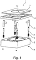
- the device 1 comprises a base element 2 designed as a housing in the form of a cuboid. In the corners of the base member 2 not shown passages for receiving a respective coil spring 3 of a stop element 4 and an actuating tappet 5 are provided. A guide frame 6 and a probe element 7 complete the device 1 to the top. On the bottom fixing elements 8 are shown, which are connected during assembly with the stop elements 4.
- FIG. 1 a device is shown which centrally has a circular receptacle 9 for further operating units, for example, rotary elements or corresponding units.
- FIG. 2 is a closed variant of a device 1 shown, but otherwise the device according to FIG. 1 equivalent.
- the coil spring 3 and an extension sleeve 11 are arranged in the intermediate space 10 between actuating plunger 5 and stop element 4.
- the coil spring 3 presses via a stop 12 on the base member 2 and the extension sleeve 11 and the actuating plunger 5 upwards in the direction of arrow R.
- an annular, inwardly projecting projection 13 is brought into abutment with an upper stop 14 of the stop element 4.
- a lower stop 15 is attached to the stop element 4, which is supported on an outer stop surface 16 of the base part 2.
- the sections A1 and A2 are in the FIGS. 3A , B and 4A, B are shown enlarged.
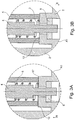
- FIG. 3A shows a lower image section A1 FIG. 2 In the unactuated position of the device 1.
- the actuating plunger 5 is lifted upwards in the direction R, so that a gap 17 between the actuating plunger 5 and an inner stop surface 12 of the base element 2 results.
- the gap that is, the width of this gap is determined by the distance between the stops of the stop element 4 and is set by exact positioning of the fixing element 8 during assembly with subsequent fixation on the stop element more accurate than would be feasible by the manufacturing tolerance of the components involved.
- FIG. 3B the same image section A1 is shown in the actuated position.
- the gap 17 is closed and the actuating plunger 5 abuts against the inner stop surface 12 of the base element 2. Since the stopper member 4 is movable relative to the actuating tappet, the stopper member 4 in the position according to FIG. 3A remain as in FIG. 3B is shown.
- the gap 18 results between the stop member 4 and the actuating plunger 5 in the actuated position according to FIG. 4B while this gap in the unactuated position according to FIG. 4A closed is.
- the invention includes a further improvement by the elastic configuration of the stop element 4 and / or the actuating plunger 5 in the transverse direction Q transverse to the actuation direction.
- the scanning element can also be moved in the transverse direction Q during operation, resulting in a better feel in the sense of improved feedback on the actuation of the feeler element for the user, in particular for very small actuation paths.
Landscapes
- Engineering & Computer Science (AREA)
- Chemical & Material Sciences (AREA)
- Combustion & Propulsion (AREA)
- Transportation (AREA)
- Mechanical Engineering (AREA)
- Physics & Mathematics (AREA)
- General Physics & Mathematics (AREA)
- Automation & Control Theory (AREA)
- Mechanical Control Devices (AREA)
Abstract
Description
- Die Erfindung betrifft eine Vorrichtung zur mechanischen Betätigung einer elektrischen oder elektronischen Eingabeeinheit nach dem Oberbegriff des Anspruchs 1.
- In vielen handelsüblichen Eingabeeinheiten, insbesondere in Mittelkonsoleneinheiten von Kraftfahrzeugen sind Eingabeeinheiten im Einsatz, die durch Drücken mit minimalem Betätigungsweg zu betätigen sind. Hierbei stellt sich das Problem, eine Haptik zu erzeugen, die eine zuverlässige Eingabe mit guter Rückmeldung an den Bediener bewirkt.
- Oftmals sind zusätzliche drehbar gelagerte Drehelemente im Einsatz, wobei durch Drehen des Drehelementes eine Datenauswahl in einem Display für eine Bedienperson ermöglicht wird. Dies ist häufig in Verbindung mit zentralen Multimediaeinheiten der Fall, wobei über derartige Eingabeelemente beispielsweise das Navigationsgerät, das Radiogerät, das Telefongerät, usw. zu bedienen sind. Nach Auswahl eines bestimmten Eingabedatums, beispielsweise eines Buchstabens, einer Zahl oder aber auch eines Menüinhaltes, kann diese Eingabe durch Bestätigung vollzogen werden.
- In dem o.a. genannten Fall wird gegebenenfalls auch die unmittelbare Umgebung des Drehelementes als Eingabefläche verwendet, so dass die o.a. Haptik auch für eine solche Umgebungsfläche gewünscht wird.
- Aufgabe der Erfindung ist es, die Druckbetätigung einer solchen Bedienfläche mit einer Rückstellung bei kleinstem Betätigungsweg und verbesserter Haptik zu ermöglichen.
- Diese Aufgabe wird ausgehend von einer Vorrichtung gemäß dem Oberbegriff der Ansprüche 1 und 10 durch deren kennzeichnende Merkmale gelöst.
- Dementsprechend zeichnet sich eine erfindungsgemäße Vorrichtung der einleitend genannten Art dadurch aus, dass ein Anschlagelement vorgesehen ist, das durch Positionierung und Fixierung am Basiselement im Zuge der Montage den Bewegungsweg des Tastelementes auf ein vorbestimmtes Spaltmaß begrenzt.
- Auf diese Weise sind Spaltmaße auf ein vorgegebenes Maß einstellbar, das im Herstellungsprozess der Bauteile mittels der Bauteiltoleranzen nicht erreichbar ist. Um das Spaltmaß auf einen minimalen Spalt mit vertretbarem Aufwand präzise einzuhalten, schlägt die Erfindung daher gewissermaßen den Toleranzausgleich in der Fertigungstoleranz der Bauteile dadurch vor, dass die gewünschte Genauigkeit des Spaltmaßes während der Montage eingestellt wird.
- Die Positionierung kann dabei beispielsweise über eine exakte arbeitende Montagevorrichtung, wie einen Montageroboter oder dergleichen vorgenommen werden. Auch die Verwendung einer Maßlehre, um fügetechnisch ein genaues Spaltmaß zu erzeugen, ist erfindungsgemäß denkbar. Nach der Positionierung des Anschlagelementes kann dieses durch ein Fixierelement, das am Anschlagelement und/oder am Basisteil fixiert wird, dauerhaft eingestellt werden.
- In einer besonderen Ausführungsform der Erfindung wird das Anschlagelement als Zugelement ausgebildet, das mit einem gegenüber dem Basiselement ortsfesten Anschlag und mit einem auf einen Betätigungsstößel wirkenden Anschlag versehen ist. Ein derart ausgebildetes Anschlagelement kann über die beiden Anschläge als Wegbegrenzung für den Betätigungsweg eingesetzt werden. Diese Wegbegrenzung wird, wie bereits oben erwähnt, durch Positionierung und Fixierung des Fixierelementes am Anschlagelement präziser ausgebildet, als die einzelnen Bauteile aufgrund der Fertigungstoleranz gefertigt sind.
- In einer Weiterbildung dieser Ausführungsform wird der Betätigungsstößel so ausgebildet, dass er das Anschlagelement und ein Rückstellelement umgibt. Diese Bauform ermöglicht eine kompakt mechanische Einheit bestehend aus Betätigungsstößel, Anschlagelement und Rückstellelement.
- Bevorzugt wird das zurückstellen hierbei zwischen einem ortsfest zum Basiselement ausgebildeten Anschlag und einem auf den Betätigungsstößel wirkenden Anschlag eingespannt. Durch diese Vorspannung ist die Rückstellkraft auf den Betätigungsstößel ebenfalls einstellbar.
- Diese Ausführung ist beispielsweise durch Verwendung einer Spiralfeder als Rückstellungelement besonders vorteilhaft, insbesondere dann, wenn der Betätigungsstößel einen Innenraum zur Aufnahme einer solchen Spiralfeder aufweist.
- In einer Weiterbildung der Erfindung wird ein Verlängerungselement, beispielsweise eine Verlängerungshülse zur Übertragung der Federkraft im Anschluss an die Spiralfeder vorgesehen. In einer besonderen Ausführung der Erfindung wird dieses Verlängerungselement als Verlängerungshülse in einem Zwischenraum zwischen dem Anschlagelement und dem Betätigungselement angeordnet. Zum einen kann hierdurch eine kürzere Spiralfeder verwendet werden, zum anderen ist über die Länge der Verlängerungshülse wiederum eine Möglichkeit zur Einstellung der Vorspannung gegeben.
- In einer besonders vorteilhaften Weiterbildung der Erfindung wird das Anschlagelement und/oder das Betätigungselement quer zur Betätigungsrichtung elastisch verformbar ausgebildet. Dies hat zur Folge, dass beim Drücken des Tastelementes nicht nur im Rahmen des voreingestellten Spaltmaßes eine Bewegung in Betätigungsrichtung stattfindet, sondern das zugleich das Tastelement auch in eine quer, beispielsweise orthogonal hierzu verlaufende Richtung beweglich ist. Hieraus ergibt sich eine vorteilhafte Haptik für den Benutzer. Die Rückmeldung für den Benutzer, dass die Betätigung erfolgt ist, wird durch eine solche zusätzlich quer verlaufende Beweglichkeit insbesondere bei den angestrebten minimal kurzen Betätigungswegen verbessert.
- Eine erfindungsgemäße Betätigungsvorrichtung wird durch ein oder mehrere Sensoreinheiten bzw. ein oder mehrere Aktoreinheiten vervollständigt, um die Betätigung des Tastelementes elektrisch oder elektronisch zu erfassen und/oder gewünschte Ereignisse auszulösen.
- Für die erfindungsgemäße Fixierung des Fixierelementes am Anschlagelement kommen verschiedene Befestigungsvarianten infrage. Das Fixierelement kann am Anschlagelement beispielsweise verschraubt, verschweißt, verklebt oder verklemmt werden.
- Ein Ausführungsbeispiel der Erfindung ist in der Zeichnung dargestellt und wird anhand der Figuren nachfolgend näher erläutert.
- Im Einzelnen zeigen
-
Figur 1 eine Explosivdarstellung einer erfindungsgemäßen Vorrichtung in perspektivischer Ansicht, -
Figur 2 einen Querschnitt durch eine weitere Ausführungsform der Erfindung, -
Figuren 3A und 3B jeweils eine Ausschnittvergrößerung aus - Figur zwei in verschiedenen Betätigungsstellungen und
-
Figuren 4A und 4B eine weitere Ausschnittvergrößerung aus -
Figur 2 in den Betätigungsstellungen gemäß denFiguren 3A und 3B . - Die Vorrichtung 1 gemäß
Figur 1 umfasst ein als Gehäuse ausgebildetes Basiselement 2 in Form eines Quaders. In den Ecken des Basiselementes 2 sind nicht näher dargestellte Durchlässe zur Aufnahme jeweils einer Spiralfeder 3 eines Anschlagelementes 4 sowie eine Betätigungsstößels 5 vorgesehen. Ein Führungsrahmen 6 sowie ein Tastelement 7 vervollständigen die Vorrichtung 1 zur Oberseite hin. Auf der Unterseite sind Fixierelemente 8 eingezeichnet, die während der Montage mit den Anschlagelementen 4 verbunden werden. - In
Figur 1 ist eine Vorrichtung dargestellt, die zentral eine kreisrunde Aufnahme 9 für weitere Betätigungseinheiten, beispielsweise Drehelemente oder entsprechende Baueinheiten aufweist. - In
Figur 2 ist eine geschlossene Variante einer Vorrichtung 1 dargestellt, die aber ansonsten der Vorrichtung gemäßFigur 1 entspricht. - Hier ist insbesondere erkennbar, dass im Zwischenraum 10 zwischen Betätigungsstößel 5 und Anschlagelement 4 die Spiralfeder 3 sowie eine Verlängerungshülse 11 angeordnet sind. Die Spiralfeder 3 drückt über einen Anschlag 12 am Basiselement 2 sowie die Verlängerungshülse 11 und den Betätigungsstößel 5 nach oben in Richtung des Pfeils R. Dabei wird ein ringförmiger, nach innen stehender Vorsprung 13 mit einem oberen Anschlag 14 des Anschlagelementes 4 in Anschlag gebracht.
- Über die Positionierung und Fixierung des Fixierelementes 8 auf der Unterseite des Anschlagelementes 4 wird ein unterer Anschlag 15 am Anschlagelement 4 angebracht, der sich an einer äußeren Anschlagfläche 16 des Basisteils 2 abstützt.
- Die Ausschnitte A1 und A2 sind in den
Figuren 3A , B und 4A, B vergrößert dargestellt. -
Figur 3A zeigt einen unteren Bildausschnitt A1 ausFigur 2 in der unbetätigten Stellung der Vorrichtung 1. Durch die Rückstellkraft der Spiralfeder 3 ist der Betätigungsstößel 5 nach oben in Richtung R gehoben, so dass sich ein Spalt 17 zwischen dem Betätigungsstößel 5 und einer inneren Anschlagfläche 12 des Basiselementes 2 ergibt. Das Spaltmaß, d.h. die Breite dieses Spaltes ist, wird durch den Abstand der Anschläge des Anschlagelementes 4 bestimmt und ist durch exakte Positionierung des Fixierelementes 8 während der Montage mit anschließender Fixierung am Anschlagelement exakter eingestellt als dies durch die Fertigungstoleranz der beteiligten Bauelemente realisierbar wäre. - In
Figur 3B ist der gleiche Bildausschnitt A1 in der betätigten Stellung dargestellt. Der Spalt 17 ist geschlossen und der Betätigungsstößel 5 liegt an der inneren Anschlagfläche 12 des Basiselementes 2 an. Da das Anschlagelement 4 gegenüber dem Betätigungsstößel beweglich ist, kann das Anschlagelement 4 in der Position gemäßFigur 3A verbleiben, so wie dies inFigur 3B dargestellt ist. - Im Bildausschnitt A2 gemäß den
Figuren 4A und 4B liegt eine entsprechende Spaltbildung vor. Hier ergibt sich der Spalt 18 zwischen dem Anschlagelement 4 und dem Betätigungsstößel 5 in der betätigten Stellung gemäßFigur 4B , während dieser Spalt in der unbetätigten Stellung gemäßFigur 4A geschlossen ist. - Ergänzend zum genauen Spaltmaß durch die erfindungsgemäße Verwendung des Fixierelementes 8 beinhaltet die Erfindung noch eine weitere Verbesserung durch die elastische Ausgestaltung des Anschlagelementes 4 und/oder des Betätigungsstößels 5 in Querrichtung Q quer zur Betätigungsrichtung. Hierdurch kann das Tastelement bei Bedienung auch in Querrichtung Q bewegt werden, wodurch sich insbesondere bei sehr kleinen Betätigungswegen eine bessere Haptik im Sinne einer verbesserten Rückmeldung über die Betätigung des Tastelementes für den Benutzer ergibt.
-
- 1.
- Vorrichtung
- 2.
- Basiselement
- 3.
- Spiralfeder
- 4.
- Anschlagelement
- 5.
- Betätigungsstößel
- 6.
- Führungsrahmen
- 7.
- Tastelement
- 8.
- Fixierelement
- 9.
- Aufnahme
- 10.
- Zwischenraum
- 11.
- Verlängerungshülse
- 12.
- Innere Anschlagfläche
- 13.
- Vorsprung
- 14.
- Anschlag
- 15.
- Anschlag
- 16.
- Äußere Anschlagfläche
- 17.
- Spalt
- 18.
- Spalt
- R
- Rückstellrichtung
- B
- Betätigungsrichtung
- Q
- Querrichtung
- A1
- Bildausschnitt
- A2
- Bildausschnitt
Claims (10)
- Vorrichtung 1 zur mechanischen Betätigung einer elektrischen oder elektronischen Eingabeeinheit, insbesondere für Mittelkonsoleinheiten von Kfz, wobei ein Tastelement 7 zur Betätigung einer Sensoreinheit und/oder einer Aktoreinheit in einer Betätigungsrichtung gegenüber einem Basiselement 2 gegen eine Rückstellkraft bewegbar ist, dadurch gekennzeichnet, dass ein Anschlagelement 4 vorgesehen ist, das durch Positionierung und Fixierung am Basiselement 2 im Zuge der Montage den Bewegungsweg des Tastelementes 7 auf ein vorbestimmtes Spaltmaß begrenzt.
- Vorrichtung nach Anspruch 1, dadurch gekennzeichnet, dass das Anschlagelement 4 als Zugelement mit einem gegenüber dem Basiselement 2 wirkenden Anschlag 15 und mit einem auf ein Betätigungselement 5 wirkenden Anschlag 14 ausgebildet ist.
- Vorrichtung nach einem der Ansprüche 1 oder 2 dadurch gekennzeichnet, dass das Betätigungselement 5 das Anschlagelement 4 und ein Rückstellelement 3 umgibt.
- Vorrichtung nach einem der vorgenannten Ansprüche, dadurch gekennzeichnet, dass das Rückstellelement 3 zwischen einer ortsfest zum Basiselement ausgebildeten Anschlagfläche 12 und einem auf das Betätigungselement 5 wirkenden Anschlag 13 eingespannt ist.
- Vorrichtung nach einem der vorgenannten Ansprüche dadurch gekennzeichnet, dass das Rückstellelement 3 eine Spiralfeder ist.
- Vorrichtung nach einem der vorgenannten Ansprüche, dadurch gekennzeichnet, dass eine Verlängerungshülse 11 zur Übertragung der Federkraft im Anschluss an die Spiralfeder 3 in einem Zwischenraum 10 zwischen dem Anschlagelement 4 und dem Betätigungselement 5 angeordnet ist.
- Vorrichtung nach einem der vorgenannten Ansprüche dadurch gekennzeichnet, dass das Anschlagelement 4 und/oder das Betätigungselement 5 quer zur Betätigungsrichtung elastisch verformbar sind.
- Vorrichtung nach einem der vorgenannten Ansprüche, dass ein oder mehrere Sensoreinheiten und /oder ein oder mehrere Aktoreinheiten zur elektrischen oder elektronischen Erfassung der Betätigung und/oder Auslösung eines Ereignisses vorgesehen sind.
- Verfahren zur Montage einer Vorrichtung nach einem der vorgenannten Ansprüche, dadurch gekennzeichnet, dass das Anschlagelement 4 oder das mit dem Anschlagelement 5 in Wirkverbindung stehende Betätigungselement 5 in einer vorbestimmten Position mit einem definierten Spaltmaß zu einem Gegenanschlag angeordnet und gehalten wird, wobei anschließend ein Fixierelement 8 mit einer Anschlagfläche zur dauerhaften Einstellung des Spaltmaßes fest mit dem Anschlagelement 4 verbunden wird.
- Verfahren nach Anspruch 9, dadurch gekennzeichnet, dass das Fixierelement 8 am Anschlagelement 4 verschraubt und/oder verschweißt und/oder verklebt und/oder verklemmt wird.
Applications Claiming Priority (1)
| Application Number | Priority Date | Filing Date | Title |
|---|---|---|---|
| DE102017120411.3A DE102017120411A1 (de) | 2017-09-05 | 2017-09-05 | Vorrichtung zur mechanischen Betätigung einer elektrischen oder elektronischen Eingabeeinheit |
Publications (2)
| Publication Number | Publication Date |
|---|---|
| EP3450243A1 true EP3450243A1 (de) | 2019-03-06 |
| EP3450243B1 EP3450243B1 (de) | 2020-11-25 |
Family
ID=63350377
Family Applications (1)
| Application Number | Title | Priority Date | Filing Date |
|---|---|---|---|
| EP18189883.4A Active EP3450243B1 (de) | 2017-09-05 | 2018-08-21 | Vorrichtung zur mechanischen betätigung einer elektrischen oder elektronischen eingabeeinheit |
Country Status (2)
| Country | Link |
|---|---|
| EP (1) | EP3450243B1 (de) |
| DE (1) | DE102017120411A1 (de) |
Citations (3)
| Publication number | Priority date | Publication date | Assignee | Title |
|---|---|---|---|---|
| JPS59154738U (ja) * | 1983-04-04 | 1984-10-17 | サンデン株式会社 | 押しボタンスイツチ部の構造 |
| DE102015008573A1 (de) * | 2015-07-02 | 2017-01-05 | Audi Ag | Kraftfahrzeug-Bedienvorrichtung mit zentriertem Betätigungselement |
| WO2017001033A1 (de) * | 2015-07-02 | 2017-01-05 | Audi Ag | Kraftfahrzeug-bedienvorrichtung mit haptischer rückmeldung |
Family Cites Families (2)
| Publication number | Priority date | Publication date | Assignee | Title |
|---|---|---|---|---|
| DE19507607C2 (de) * | 1995-03-04 | 1998-12-10 | Kaercher Gmbh & Co Alfred | Fahrbare Kehrvorrichtung |
| EP2680438B1 (de) * | 2012-06-29 | 2018-10-10 | Dav | Berührungssteuerungsmodul |
-
2017
- 2017-09-05 DE DE102017120411.3A patent/DE102017120411A1/de not_active Withdrawn
-
2018
- 2018-08-21 EP EP18189883.4A patent/EP3450243B1/de active Active
Patent Citations (3)
| Publication number | Priority date | Publication date | Assignee | Title |
|---|---|---|---|---|
| JPS59154738U (ja) * | 1983-04-04 | 1984-10-17 | サンデン株式会社 | 押しボタンスイツチ部の構造 |
| DE102015008573A1 (de) * | 2015-07-02 | 2017-01-05 | Audi Ag | Kraftfahrzeug-Bedienvorrichtung mit zentriertem Betätigungselement |
| WO2017001033A1 (de) * | 2015-07-02 | 2017-01-05 | Audi Ag | Kraftfahrzeug-bedienvorrichtung mit haptischer rückmeldung |
Also Published As
| Publication number | Publication date |
|---|---|
| DE102017120411A1 (de) | 2019-03-21 |
| EP3450243B1 (de) | 2020-11-25 |
Similar Documents
| Publication | Publication Date | Title |
|---|---|---|
| EP2920665B1 (de) | Bedienvorrichtung für eine fahrzeugkomponente | |
| EP2761385B1 (de) | Dreh-/drück-bedienvorrichtung für ein mensch-maschine-interface | |
| EP3008741B1 (de) | Schaltbedienanordnung | |
| WO2014167076A1 (de) | Vorrichtung zur bedienung mehrerer funktionen in einem kraftfahrzeug | |
| DE102010034552A1 (de) | Drückschalter mit Kapazitätssensor und damit ausgestattete Eingabevorrichtung | |
| DE102021208150A1 (de) | Bedienvorrichtung und Bedienoberfläche für ein Fahrzeug | |
| WO2014167075A1 (de) | Vorrichtung zur bedienung mehrerer funktionen in einem kraftfahrzeug | |
| DE10241048B4 (de) | Schalteinrichtung für eine Fahrzeughupe | |
| EP4360215A1 (de) | Schaltbedienanordnung | |
| EP1907916A1 (de) | Bedienelement mit zentralem taster | |
| EP3388276B1 (de) | Bedienanordnung zum bedienen von zumindest einem elektrischen gerät mit einem kraftsensor, fahrerassistenzsystem, kraftfahrzeug sowie verfahren zum bedienen einer bedienanordnung | |
| EP3450243B1 (de) | Vorrichtung zur mechanischen betätigung einer elektrischen oder elektronischen eingabeeinheit | |
| WO2016131848A1 (de) | Schaltbedienanordnung | |
| DE102015015073A1 (de) | Bedienvorrichtung für ein Kraftfahrzeug und Verfahren zum Betreiben einer Bedienvorrichtung | |
| EP3834957B1 (de) | Verfahren zum fügen zweier bleche mit einer variablen gesamtdicke | |
| DE102012018910A1 (de) | Schaltvorrichtung zum Schalten eines elektronischen Geräts eines Kraftwagens | |
| EP2920553B1 (de) | Kapazitiver sensor zur erfassung einer relativbewegung zweier benachbarter körper | |
| DE102023206332B3 (de) | Auslösevorrichtung zum Auslösen eines Öffnungsvorgangs eines Fahrzeugteils eines Fahrzeugs und Fahrzeug | |
| DE102015008939A1 (de) | Positioniervorrichtung für ein Umformwerkzeug | |
| EP2487699B1 (de) | Kurzhubtaster | |
| DE102018128170A1 (de) | Elektrischer Schalter und Verfahren zum Herstellen eines elektrischen Schalters | |
| DE202022101792U1 (de) | Schaltbedienanordnung | |
| EP3413465B1 (de) | Bedienvorrichtung zum bedienen von zumindest einem gerät eines kraftfahrzeugs, mit einem separaten federelement als erdungsverbindung sowie kraftfahrzeug | |
| EP3450780A1 (de) | Vorrichtung zur mechanischen betätigung einer elektrischen oder elektronischen eingabeeinheit | |
| DE102016223666B4 (de) | Schalteranordnung |
Legal Events
| Date | Code | Title | Description |
|---|---|---|---|
| PUAI | Public reference made under article 153(3) epc to a published international application that has entered the european phase |
Free format text: ORIGINAL CODE: 0009012 |
|
| STAA | Information on the status of an ep patent application or granted ep patent |
Free format text: STATUS: THE APPLICATION HAS BEEN PUBLISHED |
|
| AK | Designated contracting states |
Kind code of ref document: A1 Designated state(s): AL AT BE BG CH CY CZ DE DK EE ES FI FR GB GR HR HU IE IS IT LI LT LU LV MC MK MT NL NO PL PT RO RS SE SI SK SM TR |
|
| AX | Request for extension of the european patent |
Extension state: BA ME |
|
| STAA | Information on the status of an ep patent application or granted ep patent |
Free format text: STATUS: REQUEST FOR EXAMINATION WAS MADE |
|
| 17P | Request for examination filed |
Effective date: 20190520 |
|
| RBV | Designated contracting states (corrected) |
Designated state(s): AL AT BE BG CH CY CZ DE DK EE ES FI FR GB GR HR HU IE IS IT LI LT LU LV MC MK MT NL NO PL PT RO RS SE SI SK SM TR |
|
| GRAP | Despatch of communication of intention to grant a patent |
Free format text: ORIGINAL CODE: EPIDOSNIGR1 |
|
| STAA | Information on the status of an ep patent application or granted ep patent |
Free format text: STATUS: GRANT OF PATENT IS INTENDED |
|
| INTG | Intention to grant announced |
Effective date: 20200710 |
|
| GRAS | Grant fee paid |
Free format text: ORIGINAL CODE: EPIDOSNIGR3 |
|
| GRAA | (expected) grant |
Free format text: ORIGINAL CODE: 0009210 |
|
| STAA | Information on the status of an ep patent application or granted ep patent |
Free format text: STATUS: THE PATENT HAS BEEN GRANTED |
|
| AK | Designated contracting states |
Kind code of ref document: B1 Designated state(s): AL AT BE BG CH CY CZ DE DK EE ES FI FR GB GR HR HU IE IS IT LI LT LU LV MC MK MT NL NO PL PT RO RS SE SI SK SM TR |
|
| REG | Reference to a national code |
Ref country code: GB Ref legal event code: FG4D Free format text: NOT ENGLISH |
|
| REG | Reference to a national code |
Ref country code: CH Ref legal event code: EP |
|
| REG | Reference to a national code |
Ref country code: DE Ref legal event code: R096 Ref document number: 502018003105 Country of ref document: DE |
|
| REG | Reference to a national code |
Ref country code: AT Ref legal event code: REF Ref document number: 1337904 Country of ref document: AT Kind code of ref document: T Effective date: 20201215 |
|
| REG | Reference to a national code |
Ref country code: IE Ref legal event code: FG4D Free format text: LANGUAGE OF EP DOCUMENT: GERMAN |
|
| REG | Reference to a national code |
Ref country code: NL Ref legal event code: MP Effective date: 20201125 |
|
| PG25 | Lapsed in a contracting state [announced via postgrant information from national office to epo] |
Ref country code: PT Free format text: LAPSE BECAUSE OF FAILURE TO SUBMIT A TRANSLATION OF THE DESCRIPTION OR TO PAY THE FEE WITHIN THE PRESCRIBED TIME-LIMIT Effective date: 20210325 Ref country code: RS Free format text: LAPSE BECAUSE OF FAILURE TO SUBMIT A TRANSLATION OF THE DESCRIPTION OR TO PAY THE FEE WITHIN THE PRESCRIBED TIME-LIMIT Effective date: 20201125 Ref country code: FI Free format text: LAPSE BECAUSE OF FAILURE TO SUBMIT A TRANSLATION OF THE DESCRIPTION OR TO PAY THE FEE WITHIN THE PRESCRIBED TIME-LIMIT Effective date: 20201125 Ref country code: NO Free format text: LAPSE BECAUSE OF FAILURE TO SUBMIT A TRANSLATION OF THE DESCRIPTION OR TO PAY THE FEE WITHIN THE PRESCRIBED TIME-LIMIT Effective date: 20210225 Ref country code: GR Free format text: LAPSE BECAUSE OF FAILURE TO SUBMIT A TRANSLATION OF THE DESCRIPTION OR TO PAY THE FEE WITHIN THE PRESCRIBED TIME-LIMIT Effective date: 20210226 |
|
| PG25 | Lapsed in a contracting state [announced via postgrant information from national office to epo] |
Ref country code: LV Free format text: LAPSE BECAUSE OF FAILURE TO SUBMIT A TRANSLATION OF THE DESCRIPTION OR TO PAY THE FEE WITHIN THE PRESCRIBED TIME-LIMIT Effective date: 20201125 Ref country code: IS Free format text: LAPSE BECAUSE OF FAILURE TO SUBMIT A TRANSLATION OF THE DESCRIPTION OR TO PAY THE FEE WITHIN THE PRESCRIBED TIME-LIMIT Effective date: 20210325 Ref country code: PL Free format text: LAPSE BECAUSE OF FAILURE TO SUBMIT A TRANSLATION OF THE DESCRIPTION OR TO PAY THE FEE WITHIN THE PRESCRIBED TIME-LIMIT Effective date: 20201125 Ref country code: SE Free format text: LAPSE BECAUSE OF FAILURE TO SUBMIT A TRANSLATION OF THE DESCRIPTION OR TO PAY THE FEE WITHIN THE PRESCRIBED TIME-LIMIT Effective date: 20201125 Ref country code: BG Free format text: LAPSE BECAUSE OF FAILURE TO SUBMIT A TRANSLATION OF THE DESCRIPTION OR TO PAY THE FEE WITHIN THE PRESCRIBED TIME-LIMIT Effective date: 20210225 |
|
| REG | Reference to a national code |
Ref country code: LT Ref legal event code: MG9D |
|
| PG25 | Lapsed in a contracting state [announced via postgrant information from national office to epo] |
Ref country code: HR Free format text: LAPSE BECAUSE OF FAILURE TO SUBMIT A TRANSLATION OF THE DESCRIPTION OR TO PAY THE FEE WITHIN THE PRESCRIBED TIME-LIMIT Effective date: 20201125 |
|
| PG25 | Lapsed in a contracting state [announced via postgrant information from national office to epo] |
Ref country code: LT Free format text: LAPSE BECAUSE OF FAILURE TO SUBMIT A TRANSLATION OF THE DESCRIPTION OR TO PAY THE FEE WITHIN THE PRESCRIBED TIME-LIMIT Effective date: 20201125 Ref country code: RO Free format text: LAPSE BECAUSE OF FAILURE TO SUBMIT A TRANSLATION OF THE DESCRIPTION OR TO PAY THE FEE WITHIN THE PRESCRIBED TIME-LIMIT Effective date: 20201125 Ref country code: SK Free format text: LAPSE BECAUSE OF FAILURE TO SUBMIT A TRANSLATION OF THE DESCRIPTION OR TO PAY THE FEE WITHIN THE PRESCRIBED TIME-LIMIT Effective date: 20201125 Ref country code: EE Free format text: LAPSE BECAUSE OF FAILURE TO SUBMIT A TRANSLATION OF THE DESCRIPTION OR TO PAY THE FEE WITHIN THE PRESCRIBED TIME-LIMIT Effective date: 20201125 Ref country code: CZ Free format text: LAPSE BECAUSE OF FAILURE TO SUBMIT A TRANSLATION OF THE DESCRIPTION OR TO PAY THE FEE WITHIN THE PRESCRIBED TIME-LIMIT Effective date: 20201125 Ref country code: SM Free format text: LAPSE BECAUSE OF FAILURE TO SUBMIT A TRANSLATION OF THE DESCRIPTION OR TO PAY THE FEE WITHIN THE PRESCRIBED TIME-LIMIT Effective date: 20201125 |
|
| REG | Reference to a national code |
Ref country code: DE Ref legal event code: R097 Ref document number: 502018003105 Country of ref document: DE |
|
| PG25 | Lapsed in a contracting state [announced via postgrant information from national office to epo] |
Ref country code: DK Free format text: LAPSE BECAUSE OF FAILURE TO SUBMIT A TRANSLATION OF THE DESCRIPTION OR TO PAY THE FEE WITHIN THE PRESCRIBED TIME-LIMIT Effective date: 20201125 |
|
| PLBE | No opposition filed within time limit |
Free format text: ORIGINAL CODE: 0009261 |
|
| STAA | Information on the status of an ep patent application or granted ep patent |
Free format text: STATUS: NO OPPOSITION FILED WITHIN TIME LIMIT |
|
| PG25 | Lapsed in a contracting state [announced via postgrant information from national office to epo] |
Ref country code: IT Free format text: LAPSE BECAUSE OF FAILURE TO SUBMIT A TRANSLATION OF THE DESCRIPTION OR TO PAY THE FEE WITHIN THE PRESCRIBED TIME-LIMIT Effective date: 20201125 Ref country code: NL Free format text: LAPSE BECAUSE OF FAILURE TO SUBMIT A TRANSLATION OF THE DESCRIPTION OR TO PAY THE FEE WITHIN THE PRESCRIBED TIME-LIMIT Effective date: 20201125 Ref country code: AL Free format text: LAPSE BECAUSE OF FAILURE TO SUBMIT A TRANSLATION OF THE DESCRIPTION OR TO PAY THE FEE WITHIN THE PRESCRIBED TIME-LIMIT Effective date: 20201125 |
|
| 26N | No opposition filed |
Effective date: 20210826 |
|
| PG25 | Lapsed in a contracting state [announced via postgrant information from national office to epo] |
Ref country code: SI Free format text: LAPSE BECAUSE OF FAILURE TO SUBMIT A TRANSLATION OF THE DESCRIPTION OR TO PAY THE FEE WITHIN THE PRESCRIBED TIME-LIMIT Effective date: 20201125 |
|
| PG25 | Lapsed in a contracting state [announced via postgrant information from national office to epo] |
Ref country code: ES Free format text: LAPSE BECAUSE OF FAILURE TO SUBMIT A TRANSLATION OF THE DESCRIPTION OR TO PAY THE FEE WITHIN THE PRESCRIBED TIME-LIMIT Effective date: 20201125 |
|
| REG | Reference to a national code |
Ref country code: CH Ref legal event code: PL |
|
| PG25 | Lapsed in a contracting state [announced via postgrant information from national office to epo] |
Ref country code: MC Free format text: LAPSE BECAUSE OF FAILURE TO SUBMIT A TRANSLATION OF THE DESCRIPTION OR TO PAY THE FEE WITHIN THE PRESCRIBED TIME-LIMIT Effective date: 20201125 |
|
| REG | Reference to a national code |
Ref country code: BE Ref legal event code: MM Effective date: 20210831 |
|
| PG25 | Lapsed in a contracting state [announced via postgrant information from national office to epo] |
Ref country code: LI Free format text: LAPSE BECAUSE OF NON-PAYMENT OF DUE FEES Effective date: 20210831 Ref country code: CH Free format text: LAPSE BECAUSE OF NON-PAYMENT OF DUE FEES Effective date: 20210831 |
|
| PG25 | Lapsed in a contracting state [announced via postgrant information from national office to epo] |
Ref country code: IS Free format text: LAPSE BECAUSE OF FAILURE TO SUBMIT A TRANSLATION OF THE DESCRIPTION OR TO PAY THE FEE WITHIN THE PRESCRIBED TIME-LIMIT Effective date: 20210325 Ref country code: LU Free format text: LAPSE BECAUSE OF NON-PAYMENT OF DUE FEES Effective date: 20210821 |
|
| PG25 | Lapsed in a contracting state [announced via postgrant information from national office to epo] |
Ref country code: IE Free format text: LAPSE BECAUSE OF NON-PAYMENT OF DUE FEES Effective date: 20210821 Ref country code: BE Free format text: LAPSE BECAUSE OF NON-PAYMENT OF DUE FEES Effective date: 20210831 |
|
| REG | Reference to a national code |
Ref legal event code: R082 Country of ref document: DE Ref country code: DE Ref legal event code: R082 Ref document number: 502018003105 Country of ref document: DE Representative=s name: PATENTANWAELTE STAEGER & SPERLING PARTNERSCHAF, DE |
|
| REG | Reference to a national code |
Ref country code: DE Ref legal event code: R082 Ref document number: 502018003105 Country of ref document: DE Representative=s name: PATENTANWAELTE STAEGER & SPERLING PARTNERSCHAF, DE |
|
| P01 | Opt-out of the competence of the unified patent court (upc) registered |
Effective date: 20230522 |
|
| PG25 | Lapsed in a contracting state [announced via postgrant information from national office to epo] |
Ref country code: CY Free format text: LAPSE BECAUSE OF FAILURE TO SUBMIT A TRANSLATION OF THE DESCRIPTION OR TO PAY THE FEE WITHIN THE PRESCRIBED TIME-LIMIT Effective date: 20201125 |
|
| PG25 | Lapsed in a contracting state [announced via postgrant information from national office to epo] |
Ref country code: HU Free format text: LAPSE BECAUSE OF FAILURE TO SUBMIT A TRANSLATION OF THE DESCRIPTION OR TO PAY THE FEE WITHIN THE PRESCRIBED TIME-LIMIT; INVALID AB INITIO Effective date: 20180821 |
|
| REG | Reference to a national code |
Ref country code: DE Ref legal event code: R079 Ref document number: 502018003105 Country of ref document: DE Free format text: PREVIOUS MAIN CLASS: B60K0037060000 Ipc: B60K0035100000 |
|
| PG25 | Lapsed in a contracting state [announced via postgrant information from national office to epo] |
Ref country code: MK Free format text: LAPSE BECAUSE OF FAILURE TO SUBMIT A TRANSLATION OF THE DESCRIPTION OR TO PAY THE FEE WITHIN THE PRESCRIBED TIME-LIMIT Effective date: 20201125 |
|
| PG25 | Lapsed in a contracting state [announced via postgrant information from national office to epo] |
Ref country code: TR Free format text: LAPSE BECAUSE OF FAILURE TO SUBMIT A TRANSLATION OF THE DESCRIPTION OR TO PAY THE FEE WITHIN THE PRESCRIBED TIME-LIMIT Effective date: 20201125 |
|
| PG25 | Lapsed in a contracting state [announced via postgrant information from national office to epo] |
Ref country code: MT Free format text: LAPSE BECAUSE OF FAILURE TO SUBMIT A TRANSLATION OF THE DESCRIPTION OR TO PAY THE FEE WITHIN THE PRESCRIBED TIME-LIMIT Effective date: 20201125 |
|
| REG | Reference to a national code |
Ref country code: AT Ref legal event code: MM01 Ref document number: 1337904 Country of ref document: AT Kind code of ref document: T Effective date: 20230821 |
|
| PG25 | Lapsed in a contracting state [announced via postgrant information from national office to epo] |
Ref country code: AT Free format text: LAPSE BECAUSE OF NON-PAYMENT OF DUE FEES Effective date: 20230821 |
|
| PG25 | Lapsed in a contracting state [announced via postgrant information from national office to epo] |
Ref country code: AT Free format text: LAPSE BECAUSE OF NON-PAYMENT OF DUE FEES Effective date: 20230821 |
|
| PGFP | Annual fee paid to national office [announced via postgrant information from national office to epo] |
Ref country code: DE Payment date: 20250819 Year of fee payment: 8 |
|
| PGFP | Annual fee paid to national office [announced via postgrant information from national office to epo] |
Ref country code: GB Payment date: 20250822 Year of fee payment: 8 |
|
| PGFP | Annual fee paid to national office [announced via postgrant information from national office to epo] |
Ref country code: FR Payment date: 20250821 Year of fee payment: 8 |
|
| PGFP | Annual fee paid to national office [announced via postgrant information from national office to epo] |
Ref country code: AT Payment date: 20260410 Year of fee payment: 5 |