EP3450228B1 - Conditioning system for a gas vehicle - Google Patents
Conditioning system for a gas vehicle Download PDFInfo
- Publication number
- EP3450228B1 EP3450228B1 EP18192673.4A EP18192673A EP3450228B1 EP 3450228 B1 EP3450228 B1 EP 3450228B1 EP 18192673 A EP18192673 A EP 18192673A EP 3450228 B1 EP3450228 B1 EP 3450228B1
- Authority
- EP
- European Patent Office
- Prior art keywords
- heat exchanger
- conditioning
- engine
- conduit
- fluid
- Prior art date
- Legal status (The legal status is an assumption and is not a legal conclusion. Google has not performed a legal analysis and makes no representation as to the accuracy of the status listed.)
- Active
Links
Images






Classifications
-
- B—PERFORMING OPERATIONS; TRANSPORTING
- B60—VEHICLES IN GENERAL
- B60H—ARRANGEMENTS OF HEATING, COOLING, VENTILATING OR OTHER AIR-TREATING DEVICES SPECIALLY ADAPTED FOR PASSENGER OR GOODS SPACES OF VEHICLES
- B60H1/00—Heating, cooling or ventilating devices
- B60H1/32—Cooling devices
- B60H1/3202—Cooling devices using evaporation, i.e. not including a compressor, e.g. involving fuel or water evaporation
Definitions
- the present invention concerns a conditioning system for a gas vehicle, in particular a conditioning system of a liquid natural gas (LNG) for conditioning an inner volume/object of the gas vehicle.
- LNG liquid natural gas
- Traditional conditioning systems usually comprise four elements, namely a compressor, an evaporator, an expansion valve and a condenser, which are connected to create a so-called "refrigerant cycle”.
- the energy used to allow the operation of a refrigerant cycle i.e. essentially the energy to be provided to the compressor to its operation, is high and therefore the fuel consumption of a vehicle comprising a conditioning system is considerably greater than that of a vehicle, which is devoid of the latter.
- a traditional conditioning system comprises at least the above described four elements, the costs and the space needed to house these latter and the related conduits in the vehicle are not negligible.
- An aim of the present invention is to satisfy at least one of the above mentioned needs.
- first or second are not used in a limitative way but only for sake of clarity, i.e. the presence of a “first” element does not consequently need the presence of a “second” element.
- the reference 1 globally indicates an AC system for a gas vehicle (not shown) according to an embodiment not making part of the present invention, but useful to its understanding..
- the gas vehicle comprises at least a tank 2, e.g. one or more bottles, configured to contain a compressed gas in liquid state, e.g. liquid natural gas, suitable for being used for the operation of the gas vehicle.
- a compressed gas in liquid state e.g. liquid natural gas
- the gas vehicle further comprises a gas engine 3 and a conduit 4 fluidly connecting the tank 2 to the gas engine 3.
- the gas is injected into the engine 3 from the tank 2 via conduit 4 through an injection valve 5.
- the gas which is in liquid state, is expanded to be gaseous in order to be usable for the engine 3.
- the AC system 1 comprises a main heat exchanger 7 configured to condition the air of an inner volume of the vehicle, thanks to the passage of a conditioning fluid through it.
- the main heat exchanger 7 may be a radiator realized as a single pass, counter-flow or crossflow as known in the art.
- the AC system comprises a first heat exchanger 10 placed on conduit 4 and fluidly connected to the main heat exchanger 7 via a first supply conduit 11 and a first return conduit 12, defining in this way a first sub-circuit 13 where a first conditioning fluid, i.e. a refrigerant fluid, may circulate in the heat exchanger 7, the conduits 11 and 12 and the first heat exchanger 10.
- a first conditioning fluid i.e. a refrigerant fluid
- the AC system 1 may preferably comprise a pump 15 configured to allow the circulation of the refrigerant fluid in the first circuit 13. More preferably, the pump 15 may be an electric pump.
- the first heat exchanger 10 is placed on the conduit 4 in such a way that between an inlet 10a and an outlet 10b of said heat exchanger the compressed gas of tank 2 in conduit 4 passes from liquid state to gaseous state.
- the transformation from liquid to gaseous states absorbs thermal energy from the environment, therefore cooling the refrigerant fluid circulating in the first heat exchanger 10.
- the AC system 1 may further comprise a second heat exchanger 18 placed on conduit 4 downstream with respect the first heat exchanger 10 according to the direction of the gas from the tank 2 to the engine 3.
- the second heat exchanger 18 is fluidly connected to the engine 3 via a second supply conduit 19 and a second return conduit 20.
- the second heat exchanger 18 is moreover fluidly connected to the main heat exchanger 7 thanks to a couple of auxiliary conduits 23, 24 respectively fluidly connecting the heat exchanger 7 with the second supply conduit 19 and a second return conduit 20.
- a second conditioning fluid i.e. the engine cooling fluid
- the heat exchanger 7 may circulate between the heat exchanger 7, the conduits 19, 20, 23 and 24 and the second heat exchanger 18.
- the AC system 1 may preferably comprise a pump 27 configured to allow the circulation of the engine cooling fluid in the second circuit 25. More preferably, the pump 27 may be a mechanical pump.
- the second heat exchanger 18 is placed on the conduit 4 in such a way that between an inlet 18a and an outlet 18b of said heat exchanger the expanded gas coming from the outlet 10b of the first heat exchanger in conduit 4 overheats by absorbing the thermal energy of the engine coolant fluid.
- the expanded gas is overheated to a predefined temperature in order to guarantee a correct temperature of injection in the engine 3.
- the AC system may further comprise a valve 30 configured to regulate the fluxes of the first and second fluids from conduits 11, 12, 23 and 24 with the main heat exchanger 7.
- the valve 30 is configured to fluidly connect the conduits 11, 12, 23 and 24 with a third supply conduit 31 and a second supply conduit 32 connected respectively to an inlet 7a and an outlet 7b of the heat exchanger 7.
- the valve 30 may be a six ways-two positions valve allowing, in a first position, the circulation of the refrigerant fluid of circuit 13 in the main heat exchanger 7 and, in a second position, the circulation of said engine cooling fluid of circuit 25 in the main heat exchanger 7.
- the AC system 1 may further comprise a throttle valve 35 placed upstream the second heat exchanger 18 but downstream with respect to the auxiliary conduit 23.
- the throttle valve 35 is configured to regulate the flow of engine cooling fluid into the second heat exchanger 18 and consequently the flow of the same into the auxiliary conduits 23, 24.
- the described actuated elements i.e. the valve 30, the throttle valve 35 or the pumps 15, 27 are operated electronically thanks to a control unit, e.g. the ECU of the vehicle, in a known way.
- a control unit e.g. the ECU of the vehicle
- valve 30 is positioned in order to allow the circulation of the refrigerant fluid of circuit 13 into the heat exchanger 7 to cool the inner volume of the vehicle.
- the refrigerant fluid flows through the first heat exchanger 10 and is cooled by the thermal absorption due to liquid compressed gas expansion to gaseous phase.
- the cooled refrigerant fluid flows in the first supply conduit 11, through valve 30 into the exchanger 7 where it is overheated by the thermal change with the air of the inner volume of the vehicle.
- the heated refrigerant fluid therefore come back to the first heat exchanger 10 passing through valve 30 and the first return conduit 12.
- valve 30 is positioned in order to allow the circulation of the engine coolant fluid of circuit 25 into the heat exchanger 7 to heat the inner volume of the vehicle; the throttle valve 35 is open.
- the engine coolant fluid heated by the passage in the engine 3 to cool it, flows through conduit 19 and the throttle valve 35, into the second heat exchanger 18 in order to overheat the expanded gas in conduit 4 before the injection into the engine 3.
- the cooled engine cooling fluid comes back to the engine 3 to cool this latter.
- part of the heated engine cooling fluid flows from the second supply conduit 19 to conduit 23 through the valve 31 to the heat exchanger 7 where it is cooled by the thermal exchange with the air of the inner volume of the vehicle.
- the engine cooling fluid comes back through the valve 30 through conduit 24 and mix with the engine cooling fluid coming from the second heat exchanger 18 and therefore flows to the engine 3.
- valve 30 is positioned in order to allow the circulation of the engine coolant fluid of circuit 25 into the heat exchanger 7 to heat the inner volume of the vehicle, but the throttle valve 35 is closed.
- the reference 100 globally indicates an AC system for a gas vehicle (not shown) according to an embodiment not making part of the present invention, but useful to its understanding..
- valve 30 is a four ways-two positions valve, conduit 12 fluidly connects directly the outlet 7b of the heat exchanger 7 to the outlet 10b of the first heat exchanger 10 and the conduit 24 fluidly connects an outlet of the valve 30 to conduit 20.
- the AC system 100 moreover comprises a further valve 101, fluidly connected in parallel to pump 15 on conduit 11, preferably realized as a non-return valve.
- valve 30 is positioned in order to allow the circulation of the engine coolant fluid of circuit 25 into the heat exchanger 7 to heat the inner volume of the vehicle.
- the engine coolant fluid heated by the passage in the engine 3 to cool it, flows through the conduit 19 thanks to the operation of the pump 27. Thanks to the throttle valve 35, a portion of the flow flows from conduit 23 to the valve 30 and thereby to the inlet 7a of the heat exchanger 7.
- the heated engine cooling fluid flows therefore through the valve 31 to the heat exchanger 7 where it is cooled by the thermal change with the air of the inner volume of the vehicle.
- the engine cooling fluid comes back directly to the first heat exchanger 10 where it is cooled by the thermal absorption due to liquid compressed gas expansion to gaseous phase.
- the fluid Once passed through the first heat exchanger 10, the fluid flows through the non-return valve 101, which is opened, to the valve 30 and comes back via conduit 24 to conduit 20 and therefore to the engine to cool it.
- valve 30 is positioned in order to allow the circulation of the refrigerant fluid of circuit 13 into the heat exchanger 7 to cool the inner volume of the vehicle.
- the engine cooling fluid flows through the first heat exchanger 10 and is cooled by the thermal absorption due to liquid compressed gas expansion to gaseous phase.
- the cooled engine cooling fluid flows in the first supply conduit 11, thanks to the operation of pump 15, through valve 30 into the exchanger 7 where it is overheated by the thermal change with the air of the inner volume of the vehicle.
- the heated engine cooling fluid therefore come back to the first heat exchanger 10 passing through valve 30 and the conduit 12.
- the non-return valve 101 is closed and the valve 30 is positioned so that the engine cooling fluid does not flow in conduits 23 and 24. In this way, the engine cooling fluid simply flows in circuit 25 through the second heat exchanger 18 overheating the gas flowing in conduit 14 as already described.
- the reference 200 globally indicates an AC system for a gas vehicle (not shown) according to the present invention.
- Circuit 13 therefore essentially comprises conduit 11 which fluidly connect the first heat exchanger with the heat exchanger 7, conduit 12 which is fluidly connected to conduit 19, a portion of conduit 19 and conduit 24 which fluidly connect the heat exchanger 7 with conduit 19.
- the AC system 200 moreover comprises a valve 201, fluidly interposed between conduit 19 and conduit 12, preferably realized as an electronic controlled volume flow valve.
- AC system 200 comprises moreover a sensor 202 placed on conduit 11 and configured to detect a physical entity of the fluid flowing in conduit 11.
- sensor 202 may be a temperature sensor configured to detect the temperature of the fluid flowing in the latter.
- the pump 27 may be positioned on conduit 20 instead of conduit 19.
- the electronic controlled volume flow valve 201 is configured to allow the passage of the majority of the engine cooling fluid in circuit 25 and only a few portion in conduit 12 and therefore in circuit 13.
- the engine cooling fluid flows from engine 3 to the second heat exchanger 18 via conduit 20 and overheat the gas flowing in conduit 14 and therefore flows through valve 201 for its majority directly back to engine 3.
- a few portion of the engine cooling fluid is spilled by valve 201 and flows via conduit 12 to the first heat exchanger 10 where it is cooled by the gas phase transformation. From the first heat exchanger 10 the cooled fluid flows through the exchanger 7 where it is overheated by the thermal change with the air of the inner volume of the vehicle.
- the heated engine cooling fluid therefore comes back via conduit 24 directly to the engine 3 together with the majority of the flow coming from the valve 201 via conduit 19.
- the electronic controlled volume flow valve 201 is configured to allow the passage of the majority of the engine cooling fluid in circuit 13 via conduit 12 and only a few portion in the remaining portion of conduit 19 and therefore in circuit 25.
- the engine cooling fluid flows from engine 3 to the second heat exchanger 18 via conduit 20 and overheat the gas flowing in conduit 14.
- the fluid coming from second heat exchanger is spilled by valve 201 and flows via conduit 12 to the first heat exchanger 10 where it is cooled by the gas phase transformation. From the first heat exchanger 10 the cooled fluid flows through the exchanger 7 where it is again cooled by the thermal change with the air of the inner volume of the vehicle.
- the cooled engine cooling fluid therefore comes back via conduit 24 directly to the engine 3 together with the few portion of the flow coming from the valve 201 via conduit 19.
- the temperature sensor 202 may be advantageously electronically connected to the valve 201 in order to regulate the flow of the fluid in conduits 12 and 19 in order regulate the temperature of the fluid passing through exchanger 7. In this way the user can select between various values of temperature both in the cooling phase, when the fluid flowing in circuit 13 is less than the fluid flowing in circuit 25, and in heating phase, when the fluid flowing in circuit 13 is more than the fluid flowing in circuit 25.
- the reference 300 globally indicates an AC system for a gas vehicle (not shown) according to an embodiment not making part of the present invention, but useful to its understanding.
- the AC system 300 comprises, instead of first and second heat exchangers 10, 18, a single heat exchanger 301 comprising an inlet 301a and an outlet 301b for the gas flowing through it via conduit 14.
- Circuit 13 of AC system 300 therefore essentially comprises conduit 11 which fluidly connect heat exchanger 301 with the heat exchanger 7, and conduit 24 which fluidly connect the heat exchanger 7 with conduit 19.
- Circuit 25 of AC system 300 consequently comprises conduits 19 and 20 which fluidly connects the engine 3 to the heat exchanger 301.
- the AC system 300 moreover comprises the throttle valve 35 placed preferably on conduit 19 downstream with respect the heat exchanger 301 according to circuit 25.
- AC system 300 further comprises the temperature sensor 202 placed on conduit 11 and configured to detect the temperature of the fluid flowing in the latter.
- the pump 27 is positioned on conduit 20 instead of conduit 19.
- the throttle valve 35 is configured to allow the passage of the majority of the engine cooling fluid in circuit 25 and only a few portion in conduit 11 and therefore in circuit 13.
- the engine cooling fluid flows from engine 3 to the heat exchanger 301 via conduit 20 and overheat the gas flowing in conduit 14; a majority of such fluid flows directly back to engine 3 via conduit 19 thanks to the opening of throttle valve 35.
- a few portion of the engine cooling fluid continues to flow through the exchanger 301 becoming increasingly cooled by the gas phase transformation and flows via conduit 11 to the exchanger 7 where it is overheated by the thermal change with the air of the inner volume of the vehicle.
- the heated engine cooling fluid therefore comes back via conduit 24 directly to the engine 3 together with the majority of the flow coming from the valve 35 via conduit 19.
- the throttle valve 35 is configured to allow the passage of the majority of the engine cooling fluid in circuit 13 via conduit 11 and only a few portion in the remaining portion of conduit 19 and therefore in circuit 25.
- the engine cooling fluid flows from engine 3 to the heat exchanger 301 via conduit 20 and overheat the gas flowing in conduit 14. Only a few portion of the cooling engine fluid is spilled by throttle valve 35 via conduit 19, the majority continues to flow through the exchanger 301 and is cooled by the gas change transformation. This cooled, but still hot, fluid flows through the exchanger 7 where it is again cooled by the thermal change with the air of the inner volume of the vehicle. The cooled cooling fluid therefore comes back via conduit 24 directly to the engine 3 together with the few portion of the flow coming from the valve 35 via conduit 19.
- the temperature sensor 202 may be advantageously electronically connected to the valve 35 in order to regulate the flow of the fluid in conduits 12 and 19 in order regulate the temperature of the fluid passing through exchanger 7. In this way the user can select between various values of temperature both in the cooling phase, when the fluid flowing in circuit 13 is less than the fluid flowing in circuit 25, and in heating phase, when the fluid flowing in circuit 13 is more than the fluid flowing in circuit 25.
- Figures 14 and 15 discloses further two alternative embodiments of the fourth embodiment of figure 11 where the position of throttle valve 35 and pump 27 are varied on conduits 11, 19 or 20. Since the operation of these two alternative embodiments is analogous to the operation of the fourth embodiment, it will be not repeated for sake of brevity being evident to one skilled in the art in the light of aforementioned fourth embodiment.
- the energy which is usually consumed by the compressor is not used in the conditioning system of the present invention, since the cooling is realized by profiting of the thermal expansion of an already compressed gas, i.e. the compressed liquid gas.
- valves in sub-circuits 13 and 25 it is possible to manage the engine cooling fluid and use the latter both for cooling and for heating through main heat exchanger 7.
- the conditioning system of the present invention may be used for different conditioning necessities of a gas vehicle, i.e. conditioning of electric equipment, not only for conditioning of the inner volume of the vehicle.
- valves 30, 35 may be realized in a different way, or the pumps 15, 27, 35 may be substituted by equivalent devices. Obviously, other topography of circuits may be used.
Landscapes
- Physics & Mathematics (AREA)
- Thermal Sciences (AREA)
- Engineering & Computer Science (AREA)
- Mechanical Engineering (AREA)
- Air-Conditioning For Vehicles (AREA)
Description
- The present invention concerns a conditioning system for a gas vehicle, in particular a conditioning system of a liquid natural gas (LNG) for conditioning an inner volume/object of the gas vehicle.
- Traditional conditioning systems use the change of phase of a fluid, called the refrigerant, from a compressed liquid state to a gaseous state, or vice-versa, for exchanging thermal energy with the object of the conditioning, e.g. the air or an electronic equipment.
- Traditional conditioning systems usually comprise four elements, namely a compressor, an evaporator, an expansion valve and a condenser, which are connected to create a so-called "refrigerant cycle".
- However, the energy used to allow the operation of a refrigerant cycle, i.e. essentially the energy to be provided to the compressor to its operation, is high and therefore the fuel consumption of a vehicle comprising a conditioning system is considerably greater than that of a vehicle, which is devoid of the latter.
- Moreover, since a traditional conditioning system comprises at least the above described four elements, the costs and the space needed to house these latter and the related conduits in the vehicle are not negligible.
- Examples of traditional known condition systems are disclosed in documents
WG2002060710 A1 ,US5560212 A orUS3640337 A . - Therefore, the need is felt to improve existing conditioning systems in order to decrease the fuel consumption of the vehicles comprising such systems and to reduce their encumbrance and their costs.
- An aim of the present invention is to satisfy at least one of the above mentioned needs.
- The aforementioned aim is reached by a system for a vehicle and a vehicle comprising this latter according to the appended set of claims.
- For a better understanding of the present invention, a preferred embodiment is described in the following, by way of a non-limiting example, with reference to the attached drawings wherein:
-
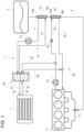
Figure 1 is a schematic representation of a conditioning system according to an embodiment not making part of the present invention, but useful to its understanding; -
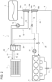
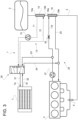
Figures 2 to 4 are schematic representations of different phases of the operation of the system offigure 1 ; -
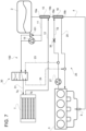
Figure 5 is a schematic representation of a conditioning system according to an embodiment not making part of the present invention, but useful to its understanding;Figures 6 and7 are schematic representations of different phases of the operation of the system offigure 5 ; -
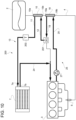
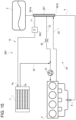
Figure 8 is a schematic representation of a conditioning system according to the present invention; -
Figures 9 and10 are schematic representations of different phases of the operation of the system offigure 8 ; -
Figure 11 is a schematic representation of a conditioning system according to an embodiment not making part of the present invention, but useful to its understanding; -
Figures 12 to 13 are schematic representations of different phases of the operation of the system offigure 11 ; and -
Figure 14 and15 are a schematic representation of a conditioning system according to further variation of the system offigure 11 . - In the annexed figures, the same reference numbers identify the same element through different embodiments. The term "first" or "second" are not used in a limitative way but only for sake of clarity, i.e. the presence of a "first" element does not consequently need the presence of a "second" element.
- For sake of simplicity the following description is related to an AC system, however it is clear that it can be applied for conditioning other elements, i.e. electronic equipment or battery packs of the vehicle.
- In
figure 1 thereference 1 globally indicates an AC system for a gas vehicle (not shown) according to an embodiment not making part of the present invention, but useful to its understanding.. - The gas vehicle comprises at least a
tank 2, e.g. one or more bottles, configured to contain a compressed gas in liquid state, e.g. liquid natural gas, suitable for being used for the operation of the gas vehicle. - In more detail, the gas vehicle further comprises a
gas engine 3 and aconduit 4 fluidly connecting thetank 2 to thegas engine 3. As known, the gas is injected into theengine 3 from thetank 2 viaconduit 4 through aninjection valve 5. During the passage in theconduit 4, the gas, which is in liquid state, is expanded to be gaseous in order to be usable for theengine 3. - The
AC system 1 comprises amain heat exchanger 7 configured to condition the air of an inner volume of the vehicle, thanks to the passage of a conditioning fluid through it. In particular, themain heat exchanger 7 may be a radiator realized as a single pass, counter-flow or crossflow as known in the art. - Advantageously the AC system comprises a
first heat exchanger 10 placed onconduit 4 and fluidly connected to themain heat exchanger 7 via afirst supply conduit 11 and afirst return conduit 12, defining in this way afirst sub-circuit 13 where a first conditioning fluid, i.e. a refrigerant fluid, may circulate in theheat exchanger 7, theconduits first heat exchanger 10. - The
AC system 1 may preferably comprise apump 15 configured to allow the circulation of the refrigerant fluid in thefirst circuit 13. More preferably, thepump 15 may be an electric pump. - The
first heat exchanger 10 is placed on theconduit 4 in such a way that between aninlet 10a and anoutlet 10b of said heat exchanger the compressed gas oftank 2 inconduit 4 passes from liquid state to gaseous state. The transformation from liquid to gaseous states absorbs thermal energy from the environment, therefore cooling the refrigerant fluid circulating in thefirst heat exchanger 10. - Advantageously the
AC system 1 may further comprise asecond heat exchanger 18 placed onconduit 4 downstream with respect thefirst heat exchanger 10 according to the direction of the gas from thetank 2 to theengine 3. Thesecond heat exchanger 18 is fluidly connected to theengine 3 via asecond supply conduit 19 and asecond return conduit 20. Thesecond heat exchanger 18 is moreover fluidly connected to themain heat exchanger 7 thanks to a couple ofauxiliary conduits heat exchanger 7 with thesecond supply conduit 19 and asecond return conduit 20. - The above described configuration defines a
sub-second circuit 25 where a second conditioning fluid, i.e. the engine cooling fluid, may circulate between theheat exchanger 7, theconduits second heat exchanger 18. - The
AC system 1 may preferably comprise apump 27 configured to allow the circulation of the engine cooling fluid in thesecond circuit 25. More preferably, thepump 27 may be a mechanical pump. - The
second heat exchanger 18 is placed on theconduit 4 in such a way that between aninlet 18a and anoutlet 18b of said heat exchanger the expanded gas coming from theoutlet 10b of the first heat exchanger inconduit 4 overheats by absorbing the thermal energy of the engine coolant fluid. The expanded gas is overheated to a predefined temperature in order to guarantee a correct temperature of injection in theengine 3. - The AC system may further comprise a
valve 30 configured to regulate the fluxes of the first and second fluids fromconduits main heat exchanger 7. In particular thevalve 30 is configured to fluidly connect theconduits third supply conduit 31 and asecond supply conduit 32 connected respectively to aninlet 7a and anoutlet 7b of theheat exchanger 7. - The
valve 30 may be a six ways-two positions valve allowing, in a first position, the circulation of the refrigerant fluid ofcircuit 13 in themain heat exchanger 7 and, in a second position, the circulation of said engine cooling fluid ofcircuit 25 in themain heat exchanger 7. - The
AC system 1 may further comprise athrottle valve 35 placed upstream thesecond heat exchanger 18 but downstream with respect to theauxiliary conduit 23. Thethrottle valve 35 is configured to regulate the flow of engine cooling fluid into thesecond heat exchanger 18 and consequently the flow of the same into theauxiliary conduits - Preferably, the described actuated elements, i.e. the
valve 30, thethrottle valve 35 or thepumps - The operation of the above described embodiment of the
AC system 1 is the following. - In a first phase of operation of the above described AC system 1 (
figure 2 ), thevalve 30 is positioned in order to allow the circulation of the refrigerant fluid ofcircuit 13 into theheat exchanger 7 to cool the inner volume of the vehicle. - In such configuration, the refrigerant fluid flows through the
first heat exchanger 10 and is cooled by the thermal absorption due to liquid compressed gas expansion to gaseous phase. The cooled refrigerant fluid flows in thefirst supply conduit 11, throughvalve 30 into theexchanger 7 where it is overheated by the thermal change with the air of the inner volume of the vehicle. The heated refrigerant fluid therefore come back to thefirst heat exchanger 10 passing throughvalve 30 and thefirst return conduit 12. - In a second phase of operation of the above described AC system 1 (
figure 3 ), thevalve 30 is positioned in order to allow the circulation of the engine coolant fluid ofcircuit 25 into theheat exchanger 7 to heat the inner volume of the vehicle; thethrottle valve 35 is open. - In such configuration the engine coolant fluid, heated by the passage in the
engine 3 to cool it, flows throughconduit 19 and thethrottle valve 35, into thesecond heat exchanger 18 in order to overheat the expanded gas inconduit 4 before the injection into theengine 3. When cooled by transferring thermal energy to the expanded gas ofconduit 4, the cooled engine cooling fluid comes back to theengine 3 to cool this latter. In the meanwhile, part of the heated engine cooling fluid flows from thesecond supply conduit 19 to conduit 23 through thevalve 31 to theheat exchanger 7 where it is cooled by the thermal exchange with the air of the inner volume of the vehicle. When cooled, the engine cooling fluid comes back through thevalve 30 throughconduit 24 and mix with the engine cooling fluid coming from thesecond heat exchanger 18 and therefore flows to theengine 3. - In a third phase of operation of the above described AC system 1 (
figure 4 ), thevalve 30 is positioned in order to allow the circulation of the engine coolant fluid ofcircuit 25 into theheat exchanger 7 to heat the inner volume of the vehicle, but thethrottle valve 35 is closed. - In such configuration the engine coolant fluid, heated by the passage in the
engine 3 to cool it flows directly intoconduit 23, since thethrottle valve 35, being closed, does not allow the passage of the cooling engine fluid in thesecond heat exchanger 18. The heated engine cooling fluid flows therefore through thevalve 31 to theheat exchanger 7 where it is cooled by the thermal change with the air of the inner volume of the vehicle. When cooled, the engine cooling fluid comes back through thevalve 30 throughconduit 24 directly toengine 3. - In
figure 5 thereference 100 globally indicates an AC system for a gas vehicle (not shown) according to an embodiment not making part of the present invention, but useful to its understanding.. - With respect the AC system of the embodiment of
figure 1 , thevalve 30 is a four ways-two positions valve,conduit 12 fluidly connects directly theoutlet 7b of theheat exchanger 7 to theoutlet 10b of thefirst heat exchanger 10 and theconduit 24 fluidly connects an outlet of thevalve 30 toconduit 20. - The
AC system 100 moreover comprises afurther valve 101, fluidly connected in parallel to pump 15 onconduit 11, preferably realized as a non-return valve. - The operation of the above described embodiment of the AC system is the following.
- In a first phase of operation of the above described AC system 100 (
figure 6 ), thevalve 30 is positioned in order to allow the circulation of the engine coolant fluid ofcircuit 25 into theheat exchanger 7 to heat the inner volume of the vehicle. - In such configuration, the engine coolant fluid, heated by the passage in the
engine 3 to cool it, flows through theconduit 19 thanks to the operation of thepump 27. Thanks to thethrottle valve 35, a portion of the flow flows fromconduit 23 to thevalve 30 and thereby to theinlet 7a of theheat exchanger 7. The heated engine cooling fluid flows therefore through thevalve 31 to theheat exchanger 7 where it is cooled by the thermal change with the air of the inner volume of the vehicle. When cooled, the engine cooling fluid comes back directly to thefirst heat exchanger 10 where it is cooled by the thermal absorption due to liquid compressed gas expansion to gaseous phase. Once passed through thefirst heat exchanger 10, the fluid flows through thenon-return valve 101, which is opened, to thevalve 30 and comes back viaconduit 24 toconduit 20 and therefore to the engine to cool it. - In a second phase of operation of the above described AC system 100 (
figure 7 ), thevalve 30 is positioned in order to allow the circulation of the refrigerant fluid ofcircuit 13 into theheat exchanger 7 to cool the inner volume of the vehicle. - In such configuration, the engine cooling fluid flows through the
first heat exchanger 10 and is cooled by the thermal absorption due to liquid compressed gas expansion to gaseous phase. The cooled engine cooling fluid flows in thefirst supply conduit 11, thanks to the operation ofpump 15, throughvalve 30 into theexchanger 7 where it is overheated by the thermal change with the air of the inner volume of the vehicle. The heated engine cooling fluid therefore come back to thefirst heat exchanger 10 passing throughvalve 30 and theconduit 12. Moreover, thenon-return valve 101 is closed and thevalve 30 is positioned so that the engine cooling fluid does not flow inconduits circuit 25 through thesecond heat exchanger 18 overheating the gas flowing in conduit 14 as already described. - In
figure 8 thereference 200 globally indicates an AC system for a gas vehicle (not shown) according to the present invention. - With respect the AC system of the embodiment of
figure 1 , thevalve 30, thepump 15 and theconduit 23 are absent.Circuit 13 therefore essentially comprisesconduit 11 which fluidly connect the first heat exchanger with theheat exchanger 7,conduit 12 which is fluidly connected toconduit 19, a portion ofconduit 19 andconduit 24 which fluidly connect theheat exchanger 7 withconduit 19. - The
AC system 200 moreover comprises avalve 201, fluidly interposed betweenconduit 19 andconduit 12, preferably realized as an electronic controlled volume flow valve.AC system 200 comprises moreover asensor 202 placed onconduit 11 and configured to detect a physical entity of the fluid flowing inconduit 11. In particular,sensor 202 may be a temperature sensor configured to detect the temperature of the fluid flowing in the latter. Finally, thepump 27 may be positioned onconduit 20 instead ofconduit 19. - The operation of the above described embodiment of the AC system according to the invention is the following.
- In a first phase of operation of the above described AC system 200 (
figure 9 ), the electronic controlledvolume flow valve 201 is configured to allow the passage of the majority of the engine cooling fluid incircuit 25 and only a few portion inconduit 12 and therefore incircuit 13. In particular, the engine cooling fluid flows fromengine 3 to thesecond heat exchanger 18 viaconduit 20 and overheat the gas flowing in conduit 14 and therefore flows throughvalve 201 for its majority directly back toengine 3. A few portion of the engine cooling fluid is spilled byvalve 201 and flows viaconduit 12 to thefirst heat exchanger 10 where it is cooled by the gas phase transformation. From thefirst heat exchanger 10 the cooled fluid flows through theexchanger 7 where it is overheated by the thermal change with the air of the inner volume of the vehicle. The heated engine cooling fluid therefore comes back viaconduit 24 directly to theengine 3 together with the majority of the flow coming from thevalve 201 viaconduit 19. - In a second phase of operation of the above described AC system 200 (
figure 10 ), the electronic controlledvolume flow valve 201 is configured to allow the passage of the majority of the engine cooling fluid incircuit 13 viaconduit 12 and only a few portion in the remaining portion ofconduit 19 and therefore incircuit 25. In particular, the engine cooling fluid flows fromengine 3 to thesecond heat exchanger 18 viaconduit 20 and overheat the gas flowing in conduit 14. The fluid coming from second heat exchanger is spilled byvalve 201 and flows viaconduit 12 to thefirst heat exchanger 10 where it is cooled by the gas phase transformation. From thefirst heat exchanger 10 the cooled fluid flows through theexchanger 7 where it is again cooled by the thermal change with the air of the inner volume of the vehicle. The cooled engine cooling fluid therefore comes back viaconduit 24 directly to theengine 3 together with the few portion of the flow coming from thevalve 201 viaconduit 19. - The
temperature sensor 202 may be advantageously electronically connected to thevalve 201 in order to regulate the flow of the fluid inconduits exchanger 7. In this way the user can select between various values of temperature both in the cooling phase, when the fluid flowing incircuit 13 is less than the fluid flowing incircuit 25, and in heating phase, when the fluid flowing incircuit 13 is more than the fluid flowing incircuit 25. - In
figure 11 thereference 300 globally indicates an AC system for a gas vehicle (not shown) according to an embodiment not making part of the present invention, but useful to its understanding. - With respect the AC system of the embodiment of
figure 1 , thevalve 30, thepump 15, theconduit 23, the first andsecond heat exchangers conduit 12 are absent. TheAC system 300 comprises, instead of first andsecond heat exchangers single heat exchanger 301 comprising aninlet 301a and anoutlet 301b for the gas flowing through it via conduit 14.Circuit 13 ofAC system 300 therefore essentially comprisesconduit 11 which fluidly connectheat exchanger 301 with theheat exchanger 7, andconduit 24 which fluidly connect theheat exchanger 7 withconduit 19.Circuit 25 ofAC system 300 consequently comprisesconduits engine 3 to theheat exchanger 301. - The
AC system 300 moreover comprises thethrottle valve 35 placed preferably onconduit 19 downstream with respect theheat exchanger 301 according tocircuit 25.AC system 300 further comprises thetemperature sensor 202 placed onconduit 11 and configured to detect the temperature of the fluid flowing in the latter. Finally, thepump 27 is positioned onconduit 20 instead ofconduit 19. - The operation of the above described embodiment of the AC system is the following.
- In a first phase of operation of the above described AC system 300 (
figure 12 ), thethrottle valve 35 is configured to allow the passage of the majority of the engine cooling fluid incircuit 25 and only a few portion inconduit 11 and therefore incircuit 13. In particular, the engine cooling fluid flows fromengine 3 to theheat exchanger 301 viaconduit 20 and overheat the gas flowing in conduit 14; a majority of such fluid flows directly back toengine 3 viaconduit 19 thanks to the opening ofthrottle valve 35. A few portion of the engine cooling fluid continues to flow through theexchanger 301 becoming increasingly cooled by the gas phase transformation and flows viaconduit 11 to theexchanger 7 where it is overheated by the thermal change with the air of the inner volume of the vehicle. The heated engine cooling fluid therefore comes back viaconduit 24 directly to theengine 3 together with the majority of the flow coming from thevalve 35 viaconduit 19. - In a second phase of operation of the above described AC system 300 (
figure 13 ), thethrottle valve 35 is configured to allow the passage of the majority of the engine cooling fluid incircuit 13 viaconduit 11 and only a few portion in the remaining portion ofconduit 19 and therefore incircuit 25. In particular, the engine cooling fluid flows fromengine 3 to theheat exchanger 301 viaconduit 20 and overheat the gas flowing in conduit 14. Only a few portion of the cooling engine fluid is spilled bythrottle valve 35 viaconduit 19, the majority continues to flow through theexchanger 301 and is cooled by the gas change transformation. This cooled, but still hot, fluid flows through theexchanger 7 where it is again cooled by the thermal change with the air of the inner volume of the vehicle. The cooled cooling fluid therefore comes back viaconduit 24 directly to theengine 3 together with the few portion of the flow coming from thevalve 35 viaconduit 19. - The
temperature sensor 202 may be advantageously electronically connected to thevalve 35 in order to regulate the flow of the fluid inconduits exchanger 7. In this way the user can select between various values of temperature both in the cooling phase, when the fluid flowing incircuit 13 is less than the fluid flowing incircuit 25, and in heating phase, when the fluid flowing incircuit 13 is more than the fluid flowing incircuit 25. -
Figures 14 and15 discloses further two alternative embodiments of the fourth embodiment offigure 11 where the position ofthrottle valve 35 and pump 27 are varied onconduits - In all the aforementioned embodiments all the operable elements, i.e. valves or sensors, may be controlled by an electronic unit as already described for the first embodiment of the present invention.
- In view of the foregoing, the advantages of a conditioning system according to the invention are apparent.
- The use of the thermal absorption due to the expansion of the compressed liquid gas into gaseous phase allows to cool a refrigerant fluid without the use of the traditional elements of a refrigerant cycle such as the compressor or the evaporator.
- In view of the above, the energy which is usually consumed by the compressor is not used in the conditioning system of the present invention, since the cooling is realized by profiting of the thermal expansion of an already compressed gas, i.e. the compressed liquid gas.
- Moreover, since the aforementioned traditional elements are not present, the encumbrance and the costs of a conditioning system according to the present invention is lower with respect to a traditional conditioning system.
- Further, modifying the positioning and typologies of valves in
sub-circuits main heat exchanger 7. - It is clear that modifications can be made to the described AC system, which do not extend beyond the scope of protection defined by the claims.
- First, is clear that the conditioning system of the present invention may be used for different conditioning necessities of a gas vehicle, i.e. conditioning of electric equipment, not only for conditioning of the inner volume of the vehicle.
- Moreover, the
valves pumps
Claims (8)
- A conditioning system (1) for a gas vehicle comprising a source (2) of a gas in a compressed state, said gas being used for the operation of an engine (3) of said gas vehicle, said system (1) comprising a main heat exchanger (7) configured to use a first conditioning fluid for conditioning an inner volume/object of said gas vehicle and a first heat exchanger (10) positioned on a conduit (4) connecting said source (2) of said gas in said compressed state to said engine (3), said first heat exchanger (10) being fluidly connected to said main heat exchanger (7) and being configured to cool said first conditioning fluid thanks to the transition of said gas from said compressed state to an expanded state between an inlet (10a) and an outlet (10b) of said first heat exchanger (10);said conditioning system further comprising a second heat exchanger (18) positioned on said conduit (4) downstream with respect to said first heat exchanger (10) and being fluidly connected to said main heat exchanger (7) and to said engine (3) in order to allow the passage of a second conditioning fluid inside said main heat exchanger (7) and said second heat exchanger (18), said second heat exchanger (18) being configured to overheat said gas in said expanded state in conduit (4) thanks to the passage of said second conditioning fluid flowing from said engine (3) between an inlet (18a) and an outlet (18b) of said second heat exchanger (18);said first conditioning fluid and said second conditioning fluid being the same fluid;characterized in that said conditioning system further comprises an electronic controlled volume flow valve (201), which is directly fluidly connected to said first heat exchanger (10), said second heat exchanger (18) and said engine (3);said valve (201) being configured to receive said second conditioning fluid from said second heat exchanger (18), to allow the passage of said second conditioning fluid to said first heat exchanger (10) and to allow the passage of said second conditioning fluid to said engine (3);said valve (201) being settable in a first configuration, in which it allows the passage of the majority of the engine cooling fluid in circuit (25) and said second conditioning fluid from said second heat exchanger (18) in circuit (25) to said engine (3) to cool it and only a few portion in conduit (12) to said first heat exchanger (10) to cool said inner volume/object of said gas vehicle;said valve (201) being further settable in a second configuration, in which it allows the passage of only a few portion of said second conditioning fluid in the remaining portion of conduit (19) and therefore in circuit (25) from said second heat exchanger (18) to said engine (3) to cool it and the majority of the engine cooling fluid in circuit (13) via circuit (12)to said first heat exchanger (10) to heat said inner volume/object of said gas vehicle.
- Conditioning system according to claim 1, wherein the circulation of said first and second conditioning fluids in the respective circuits is operated by a dedicated pump (15; 27).
- Conditioning system according to claim 1 or 2, wherein said operable elements (30; 15; 27; 35) are controlled by a control unit.
- Conditioning system according to any of claims 1 to 3, further comprising a sensor (202) configured to measure a physical entity of at least one of said conditioning fluids.
- Conditioning system according to claim 4, wherein said sensor (202) is a temperature sensor.
- Vehicle comprising a conditioning system (1) according any of the preceding claims.
- Vehicle according to claim 6, wherein said control unit of said conditioning system (1) is an ECU of said vehicle.
- Vehicle according to claims 6 or 7, wherein said first and second conditioning fluids are the cooling fluid of an engine of said vehicle.
Applications Claiming Priority (1)
| Application Number | Priority Date | Filing Date | Title |
|---|---|---|---|
| IT102017000099422A IT201700099422A1 (en) | 2017-09-05 | 2017-09-05 | AIR-CONDITIONING SYSTEM FOR A GAS VEHICLE |
Publications (2)
| Publication Number | Publication Date |
|---|---|
| EP3450228A1 EP3450228A1 (en) | 2019-03-06 |
| EP3450228B1 true EP3450228B1 (en) | 2023-04-19 |
Family
ID=60766079
Family Applications (1)
| Application Number | Title | Priority Date | Filing Date |
|---|---|---|---|
| EP18192673.4A Active EP3450228B1 (en) | 2017-09-05 | 2018-09-05 | Conditioning system for a gas vehicle |
Country Status (2)
| Country | Link |
|---|---|
| EP (1) | EP3450228B1 (en) |
| IT (1) | IT201700099422A1 (en) |
Family Cites Families (3)
| Publication number | Priority date | Publication date | Assignee | Title |
|---|---|---|---|---|
| US3640337A (en) * | 1970-03-13 | 1972-02-08 | Robert W Mcjones | Use of the heat of vaporization of a fuel as an air-conditioning medium for a vehicle |
| US5560212A (en) * | 1995-06-26 | 1996-10-01 | Hansen; William L. | Vehicle air conditioning system using liquid gas |
| BG105182A (en) * | 2001-01-25 | 2002-07-31 | МИТЕВ Ганчо | System and method for air cooling in transport vehicles using liquefied or compressed gas for fuel |
-
2017
- 2017-09-05 IT IT102017000099422A patent/IT201700099422A1/en unknown
-
2018
- 2018-09-05 EP EP18192673.4A patent/EP3450228B1/en active Active
Also Published As
| Publication number | Publication date |
|---|---|
| IT201700099422A1 (en) | 2019-03-05 |
| EP3450228A1 (en) | 2019-03-06 |
Similar Documents
| Publication | Publication Date | Title |
|---|---|---|
| US12240290B2 (en) | Heat pump system for vehicle | |
| EP2634020B1 (en) | Electric vehicle and thermal management system therefor | |
| JP6134129B2 (en) | Vehicle heat exchanger | |
| KR101283591B1 (en) | Heat exchanger for vehicle | |
| CN109641507A (en) | Vehicular hot pipe manages system | |
| CN107639992B (en) | Thermal management system | |
| WO2010109632A1 (en) | Temperature regulator, fluid supply system, heating system, method of fixing temperature regulator, and fluid supply method | |
| US11472261B2 (en) | Vehicle heat treatment system | |
| JP2011173543A (en) | Battery cooling/heating device | |
| EP3469199A1 (en) | A cooling system for an electric power unit in a vehicle | |
| CN113815382B (en) | Electric vehicle and its heat pump air conditioning system | |
| JPWO2015072126A1 (en) | Air conditioner for vehicle and component unit thereof | |
| EP3666565B1 (en) | Automotive air conditioning system | |
| KR102657255B1 (en) | Heat pump system for vehicle | |
| KR20180049018A (en) | Cooling device for electric power unit in vehicle | |
| CN110657018A (en) | Multi-channel thermal management system and method for gasoline engine | |
| US11413930B2 (en) | Heat treatment system for a vehicle | |
| US20220258569A1 (en) | Method for managing a thermal management device for a motor vehicle | |
| KR20060093329A (en) | Heat pump type water heater using heat energy in air | |
| KR101274247B1 (en) | Heat exchanger for vehicle | |
| EP3450228A1 (en) | Conditioning system for a gas vehicle | |
| US20100043465A1 (en) | Heat pump system and method of controlling the same | |
| CN109733182A (en) | A kind of heat management system of extended-range electric vehicle | |
| WO2023111291A1 (en) | Heating network with heating and cooling applicability | |
| JP5730237B2 (en) | Integrated cooling system |
Legal Events
| Date | Code | Title | Description |
|---|---|---|---|
| PUAI | Public reference made under article 153(3) epc to a published international application that has entered the european phase |
Free format text: ORIGINAL CODE: 0009012 |
|
| STAA | Information on the status of an ep patent application or granted ep patent |
Free format text: STATUS: THE APPLICATION HAS BEEN PUBLISHED |
|
| AK | Designated contracting states |
Kind code of ref document: A1 Designated state(s): AL AT BE BG CH CY CZ DE DK EE ES FI FR GB GR HR HU IE IS IT LI LT LU LV MC MK MT NL NO PL PT RO RS SE SI SK SM TR |
|
| AX | Request for extension of the european patent |
Extension state: BA ME |
|
| STAA | Information on the status of an ep patent application or granted ep patent |
Free format text: STATUS: REQUEST FOR EXAMINATION WAS MADE |
|
| 17P | Request for examination filed |
Effective date: 20190905 |
|
| RBV | Designated contracting states (corrected) |
Designated state(s): AL AT BE BG CH CY CZ DE DK EE ES FI FR GB GR HR HU IE IS IT LI LT LU LV MC MK MT NL NO PL PT RO RS SE SI SK SM TR |
|
| STAA | Information on the status of an ep patent application or granted ep patent |
Free format text: STATUS: EXAMINATION IS IN PROGRESS |
|
| 17Q | First examination report despatched |
Effective date: 20200724 |
|
| GRAP | Despatch of communication of intention to grant a patent |
Free format text: ORIGINAL CODE: EPIDOSNIGR1 |
|
| STAA | Information on the status of an ep patent application or granted ep patent |
Free format text: STATUS: GRANT OF PATENT IS INTENDED |
|
| INTG | Intention to grant announced |
Effective date: 20221110 |
|
| GRAS | Grant fee paid |
Free format text: ORIGINAL CODE: EPIDOSNIGR3 |
|
| GRAA | (expected) grant |
Free format text: ORIGINAL CODE: 0009210 |
|
| STAA | Information on the status of an ep patent application or granted ep patent |
Free format text: STATUS: THE PATENT HAS BEEN GRANTED |
|
| AK | Designated contracting states |
Kind code of ref document: B1 Designated state(s): AL AT BE BG CH CY CZ DE DK EE ES FI FR GB GR HR HU IE IS IT LI LT LU LV MC MK MT NL NO PL PT RO RS SE SI SK SM TR |
|
| REG | Reference to a national code |
Ref country code: GB Ref legal event code: FG4D |
|
| REG | Reference to a national code |
Ref country code: DE Ref legal event code: R082 Ref document number: 602018048505 Country of ref document: DE Representative=s name: TER MEER STEINMEISTER & PARTNER PATENTANWAELTE, DE |
|
| REG | Reference to a national code |
Ref country code: CH Ref legal event code: EP |
|
| REG | Reference to a national code |
Ref country code: DE Ref legal event code: R096 Ref document number: 602018048505 Country of ref document: DE |
|
| REG | Reference to a national code |
Ref country code: IE Ref legal event code: FG4D |
|
| REG | Reference to a national code |
Ref country code: AT Ref legal event code: REF Ref document number: 1560932 Country of ref document: AT Kind code of ref document: T Effective date: 20230515 |
|
| P01 | Opt-out of the competence of the unified patent court (upc) registered |
Effective date: 20230522 |
|
| REG | Reference to a national code |
Ref country code: LT Ref legal event code: MG9D |
|
| REG | Reference to a national code |
Ref country code: NL Ref legal event code: MP Effective date: 20230419 |
|
| REG | Reference to a national code |
Ref country code: AT Ref legal event code: MK05 Ref document number: 1560932 Country of ref document: AT Kind code of ref document: T Effective date: 20230419 |
|
| PG25 | Lapsed in a contracting state [announced via postgrant information from national office to epo] |
Ref country code: NL Free format text: LAPSE BECAUSE OF FAILURE TO SUBMIT A TRANSLATION OF THE DESCRIPTION OR TO PAY THE FEE WITHIN THE PRESCRIBED TIME-LIMIT Effective date: 20230419 |
|
| PG25 | Lapsed in a contracting state [announced via postgrant information from national office to epo] |
Ref country code: SE Free format text: LAPSE BECAUSE OF FAILURE TO SUBMIT A TRANSLATION OF THE DESCRIPTION OR TO PAY THE FEE WITHIN THE PRESCRIBED TIME-LIMIT Effective date: 20230419 Ref country code: PT Free format text: LAPSE BECAUSE OF FAILURE TO SUBMIT A TRANSLATION OF THE DESCRIPTION OR TO PAY THE FEE WITHIN THE PRESCRIBED TIME-LIMIT Effective date: 20230821 Ref country code: NO Free format text: LAPSE BECAUSE OF FAILURE TO SUBMIT A TRANSLATION OF THE DESCRIPTION OR TO PAY THE FEE WITHIN THE PRESCRIBED TIME-LIMIT Effective date: 20230719 Ref country code: ES Free format text: LAPSE BECAUSE OF FAILURE TO SUBMIT A TRANSLATION OF THE DESCRIPTION OR TO PAY THE FEE WITHIN THE PRESCRIBED TIME-LIMIT Effective date: 20230419 Ref country code: AT Free format text: LAPSE BECAUSE OF FAILURE TO SUBMIT A TRANSLATION OF THE DESCRIPTION OR TO PAY THE FEE WITHIN THE PRESCRIBED TIME-LIMIT Effective date: 20230419 |
|
| PG25 | Lapsed in a contracting state [announced via postgrant information from national office to epo] |
Ref country code: RS Free format text: LAPSE BECAUSE OF FAILURE TO SUBMIT A TRANSLATION OF THE DESCRIPTION OR TO PAY THE FEE WITHIN THE PRESCRIBED TIME-LIMIT Effective date: 20230419 Ref country code: PL Free format text: LAPSE BECAUSE OF FAILURE TO SUBMIT A TRANSLATION OF THE DESCRIPTION OR TO PAY THE FEE WITHIN THE PRESCRIBED TIME-LIMIT Effective date: 20230419 Ref country code: LV Free format text: LAPSE BECAUSE OF FAILURE TO SUBMIT A TRANSLATION OF THE DESCRIPTION OR TO PAY THE FEE WITHIN THE PRESCRIBED TIME-LIMIT Effective date: 20230419 Ref country code: LT Free format text: LAPSE BECAUSE OF FAILURE TO SUBMIT A TRANSLATION OF THE DESCRIPTION OR TO PAY THE FEE WITHIN THE PRESCRIBED TIME-LIMIT Effective date: 20230419 Ref country code: IS Free format text: LAPSE BECAUSE OF FAILURE TO SUBMIT A TRANSLATION OF THE DESCRIPTION OR TO PAY THE FEE WITHIN THE PRESCRIBED TIME-LIMIT Effective date: 20230819 Ref country code: HR Free format text: LAPSE BECAUSE OF FAILURE TO SUBMIT A TRANSLATION OF THE DESCRIPTION OR TO PAY THE FEE WITHIN THE PRESCRIBED TIME-LIMIT Effective date: 20230419 Ref country code: GR Free format text: LAPSE BECAUSE OF FAILURE TO SUBMIT A TRANSLATION OF THE DESCRIPTION OR TO PAY THE FEE WITHIN THE PRESCRIBED TIME-LIMIT Effective date: 20230720 Ref country code: AL Free format text: LAPSE BECAUSE OF FAILURE TO SUBMIT A TRANSLATION OF THE DESCRIPTION OR TO PAY THE FEE WITHIN THE PRESCRIBED TIME-LIMIT Effective date: 20230419 |
|
| PG25 | Lapsed in a contracting state [announced via postgrant information from national office to epo] |
Ref country code: FI Free format text: LAPSE BECAUSE OF FAILURE TO SUBMIT A TRANSLATION OF THE DESCRIPTION OR TO PAY THE FEE WITHIN THE PRESCRIBED TIME-LIMIT Effective date: 20230419 |
|
| PG25 | Lapsed in a contracting state [announced via postgrant information from national office to epo] |
Ref country code: SK Free format text: LAPSE BECAUSE OF FAILURE TO SUBMIT A TRANSLATION OF THE DESCRIPTION OR TO PAY THE FEE WITHIN THE PRESCRIBED TIME-LIMIT Effective date: 20230419 |
|
| REG | Reference to a national code |
Ref country code: DE Ref legal event code: R097 Ref document number: 602018048505 Country of ref document: DE |
|
| PG25 | Lapsed in a contracting state [announced via postgrant information from national office to epo] |
Ref country code: SM Free format text: LAPSE BECAUSE OF FAILURE TO SUBMIT A TRANSLATION OF THE DESCRIPTION OR TO PAY THE FEE WITHIN THE PRESCRIBED TIME-LIMIT Effective date: 20230419 Ref country code: SK Free format text: LAPSE BECAUSE OF FAILURE TO SUBMIT A TRANSLATION OF THE DESCRIPTION OR TO PAY THE FEE WITHIN THE PRESCRIBED TIME-LIMIT Effective date: 20230419 Ref country code: RO Free format text: LAPSE BECAUSE OF FAILURE TO SUBMIT A TRANSLATION OF THE DESCRIPTION OR TO PAY THE FEE WITHIN THE PRESCRIBED TIME-LIMIT Effective date: 20230419 Ref country code: EE Free format text: LAPSE BECAUSE OF FAILURE TO SUBMIT A TRANSLATION OF THE DESCRIPTION OR TO PAY THE FEE WITHIN THE PRESCRIBED TIME-LIMIT Effective date: 20230419 Ref country code: DK Free format text: LAPSE BECAUSE OF FAILURE TO SUBMIT A TRANSLATION OF THE DESCRIPTION OR TO PAY THE FEE WITHIN THE PRESCRIBED TIME-LIMIT Effective date: 20230419 Ref country code: CZ Free format text: LAPSE BECAUSE OF FAILURE TO SUBMIT A TRANSLATION OF THE DESCRIPTION OR TO PAY THE FEE WITHIN THE PRESCRIBED TIME-LIMIT Effective date: 20230419 |
|
| PLBE | No opposition filed within time limit |
Free format text: ORIGINAL CODE: 0009261 |
|
| STAA | Information on the status of an ep patent application or granted ep patent |
Free format text: STATUS: NO OPPOSITION FILED WITHIN TIME LIMIT |
|
| 26N | No opposition filed |
Effective date: 20240122 |
|
| REG | Reference to a national code |
Ref country code: CH Ref legal event code: PL |
|
| PG25 | Lapsed in a contracting state [announced via postgrant information from national office to epo] |
Ref country code: SI Free format text: LAPSE BECAUSE OF FAILURE TO SUBMIT A TRANSLATION OF THE DESCRIPTION OR TO PAY THE FEE WITHIN THE PRESCRIBED TIME-LIMIT Effective date: 20230419 |
|
| PG25 | Lapsed in a contracting state [announced via postgrant information from national office to epo] |
Ref country code: LU Free format text: LAPSE BECAUSE OF NON-PAYMENT OF DUE FEES Effective date: 20230905 |
|
| REG | Reference to a national code |
Ref country code: BE Ref legal event code: MM Effective date: 20230930 |
|
| GBPC | Gb: european patent ceased through non-payment of renewal fee |
Effective date: 20230905 |
|
| PG25 | Lapsed in a contracting state [announced via postgrant information from national office to epo] |
Ref country code: SI Free format text: LAPSE BECAUSE OF FAILURE TO SUBMIT A TRANSLATION OF THE DESCRIPTION OR TO PAY THE FEE WITHIN THE PRESCRIBED TIME-LIMIT Effective date: 20230419 Ref country code: LU Free format text: LAPSE BECAUSE OF NON-PAYMENT OF DUE FEES Effective date: 20230905 Ref country code: MC Free format text: LAPSE BECAUSE OF FAILURE TO SUBMIT A TRANSLATION OF THE DESCRIPTION OR TO PAY THE FEE WITHIN THE PRESCRIBED TIME-LIMIT Effective date: 20230419 |
|
| REG | Reference to a national code |
Ref country code: IE Ref legal event code: MM4A |
|
| PG25 | Lapsed in a contracting state [announced via postgrant information from national office to epo] |
Ref country code: IE Free format text: LAPSE BECAUSE OF NON-PAYMENT OF DUE FEES Effective date: 20230905 |
|
| PG25 | Lapsed in a contracting state [announced via postgrant information from national office to epo] |
Ref country code: GB Free format text: LAPSE BECAUSE OF NON-PAYMENT OF DUE FEES Effective date: 20230905 |
|
| PG25 | Lapsed in a contracting state [announced via postgrant information from national office to epo] |
Ref country code: CH Free format text: LAPSE BECAUSE OF NON-PAYMENT OF DUE FEES Effective date: 20230930 |
|
| PG25 | Lapsed in a contracting state [announced via postgrant information from national office to epo] |
Ref country code: IE Free format text: LAPSE BECAUSE OF NON-PAYMENT OF DUE FEES Effective date: 20230905 Ref country code: GB Free format text: LAPSE BECAUSE OF NON-PAYMENT OF DUE FEES Effective date: 20230905 Ref country code: CH Free format text: LAPSE BECAUSE OF NON-PAYMENT OF DUE FEES Effective date: 20230930 |
|
| PG25 | Lapsed in a contracting state [announced via postgrant information from national office to epo] |
Ref country code: BE Free format text: LAPSE BECAUSE OF NON-PAYMENT OF DUE FEES Effective date: 20230930 |
|
| PG25 | Lapsed in a contracting state [announced via postgrant information from national office to epo] |
Ref country code: BG Free format text: LAPSE BECAUSE OF FAILURE TO SUBMIT A TRANSLATION OF THE DESCRIPTION OR TO PAY THE FEE WITHIN THE PRESCRIBED TIME-LIMIT Effective date: 20230419 |
|
| PG25 | Lapsed in a contracting state [announced via postgrant information from national office to epo] |
Ref country code: BG Free format text: LAPSE BECAUSE OF FAILURE TO SUBMIT A TRANSLATION OF THE DESCRIPTION OR TO PAY THE FEE WITHIN THE PRESCRIBED TIME-LIMIT Effective date: 20230419 |
|
| PG25 | Lapsed in a contracting state [announced via postgrant information from national office to epo] |
Ref country code: CY Free format text: LAPSE BECAUSE OF FAILURE TO SUBMIT A TRANSLATION OF THE DESCRIPTION OR TO PAY THE FEE WITHIN THE PRESCRIBED TIME-LIMIT; INVALID AB INITIO Effective date: 20180905 |
|
| PG25 | Lapsed in a contracting state [announced via postgrant information from national office to epo] |
Ref country code: HU Free format text: LAPSE BECAUSE OF FAILURE TO SUBMIT A TRANSLATION OF THE DESCRIPTION OR TO PAY THE FEE WITHIN THE PRESCRIBED TIME-LIMIT; INVALID AB INITIO Effective date: 20180905 |
|
| PGFP | Annual fee paid to national office [announced via postgrant information from national office to epo] |
Ref country code: DE Payment date: 20250926 Year of fee payment: 8 |
|
| PGFP | Annual fee paid to national office [announced via postgrant information from national office to epo] |
Ref country code: IT Payment date: 20250909 Year of fee payment: 8 |
|
| PGFP | Annual fee paid to national office [announced via postgrant information from national office to epo] |
Ref country code: FR Payment date: 20250925 Year of fee payment: 8 |
|
| PG25 | Lapsed in a contracting state [announced via postgrant information from national office to epo] |
Ref country code: TR Free format text: LAPSE BECAUSE OF FAILURE TO SUBMIT A TRANSLATION OF THE DESCRIPTION OR TO PAY THE FEE WITHIN THE PRESCRIBED TIME-LIMIT Effective date: 20230419 |