EP3450144A1 - Member joining method - Google Patents
Member joining method Download PDFInfo
- Publication number
- EP3450144A1 EP3450144A1 EP16900472.8A EP16900472A EP3450144A1 EP 3450144 A1 EP3450144 A1 EP 3450144A1 EP 16900472 A EP16900472 A EP 16900472A EP 3450144 A1 EP3450144 A1 EP 3450144A1
- Authority
- EP
- European Patent Office
- Prior art keywords
- foamable
- resin
- joining
- joined
- pillar
- Prior art date
- Legal status (The legal status is an assumption and is not a legal conclusion. Google has not performed a legal analysis and makes no representation as to the accuracy of the status listed.)
- Granted
Links
Images






Classifications
-
- F—MECHANICAL ENGINEERING; LIGHTING; HEATING; WEAPONS; BLASTING
- F16—ENGINEERING ELEMENTS AND UNITS; GENERAL MEASURES FOR PRODUCING AND MAINTAINING EFFECTIVE FUNCTIONING OF MACHINES OR INSTALLATIONS; THERMAL INSULATION IN GENERAL
- F16B—DEVICES FOR FASTENING OR SECURING CONSTRUCTIONAL ELEMENTS OR MACHINE PARTS TOGETHER, e.g. NAILS, BOLTS, CIRCLIPS, CLAMPS, CLIPS OR WEDGES; JOINTS OR JOINTING
- F16B11/00—Connecting constructional elements or machine parts by sticking or pressing them together, e.g. cold pressure welding
- F16B11/006—Connecting constructional elements or machine parts by sticking or pressing them together, e.g. cold pressure welding by gluing
-
- B—PERFORMING OPERATIONS; TRANSPORTING
- B29—WORKING OF PLASTICS; WORKING OF SUBSTANCES IN A PLASTIC STATE IN GENERAL
- B29C—SHAPING OR JOINING OF PLASTICS; SHAPING OF MATERIAL IN A PLASTIC STATE, NOT OTHERWISE PROVIDED FOR; AFTER-TREATMENT OF THE SHAPED PRODUCTS, e.g. REPAIRING
- B29C65/00—Joining or sealing of preformed parts, e.g. welding of plastics materials; Apparatus therefor
- B29C65/02—Joining or sealing of preformed parts, e.g. welding of plastics materials; Apparatus therefor by heating, with or without pressure
-
- B—PERFORMING OPERATIONS; TRANSPORTING
- B29—WORKING OF PLASTICS; WORKING OF SUBSTANCES IN A PLASTIC STATE IN GENERAL
- B29C—SHAPING OR JOINING OF PLASTICS; SHAPING OF MATERIAL IN A PLASTIC STATE, NOT OTHERWISE PROVIDED FOR; AFTER-TREATMENT OF THE SHAPED PRODUCTS, e.g. REPAIRING
- B29C44/00—Shaping by internal pressure generated in the material, e.g. swelling or foaming ; Producing porous or cellular expanded plastics articles
- B29C44/02—Shaping by internal pressure generated in the material, e.g. swelling or foaming ; Producing porous or cellular expanded plastics articles for articles of definite length, i.e. discrete articles
- B29C44/12—Incorporating or moulding on preformed parts, e.g. inserts or reinforcements
- B29C44/128—Internally reinforcing constructional elements, e.g. beams
-
- B—PERFORMING OPERATIONS; TRANSPORTING
- B29—WORKING OF PLASTICS; WORKING OF SUBSTANCES IN A PLASTIC STATE IN GENERAL
- B29C—SHAPING OR JOINING OF PLASTICS; SHAPING OF MATERIAL IN A PLASTIC STATE, NOT OTHERWISE PROVIDED FOR; AFTER-TREATMENT OF THE SHAPED PRODUCTS, e.g. REPAIRING
- B29C44/00—Shaping by internal pressure generated in the material, e.g. swelling or foaming ; Producing porous or cellular expanded plastics articles
- B29C44/02—Shaping by internal pressure generated in the material, e.g. swelling or foaming ; Producing porous or cellular expanded plastics articles for articles of definite length, i.e. discrete articles
- B29C44/12—Incorporating or moulding on preformed parts, e.g. inserts or reinforcements
- B29C44/18—Filling preformed cavities
-
- B—PERFORMING OPERATIONS; TRANSPORTING
- B29—WORKING OF PLASTICS; WORKING OF SUBSTANCES IN A PLASTIC STATE IN GENERAL
- B29C—SHAPING OR JOINING OF PLASTICS; SHAPING OF MATERIAL IN A PLASTIC STATE, NOT OTHERWISE PROVIDED FOR; AFTER-TREATMENT OF THE SHAPED PRODUCTS, e.g. REPAIRING
- B29C66/00—General aspects of processes or apparatus for joining preformed parts
- B29C66/50—General aspects of joining tubular articles; General aspects of joining long products, i.e. bars or profiled elements; General aspects of joining single elements to tubular articles, hollow articles or bars; General aspects of joining several hollow-preforms to form hollow or tubular articles
- B29C66/51—Joining tubular articles, profiled elements or bars; Joining single elements to tubular articles, hollow articles or bars; Joining several hollow-preforms to form hollow or tubular articles
- B29C66/52—Joining tubular articles, bars or profiled elements
- B29C66/522—Joining tubular articles
- B29C66/5221—Joining tubular articles for forming coaxial connections, i.e. the tubular articles to be joined forming a zero angle relative to each other
-
- B—PERFORMING OPERATIONS; TRANSPORTING
- B29—WORKING OF PLASTICS; WORKING OF SUBSTANCES IN A PLASTIC STATE IN GENERAL
- B29C—SHAPING OR JOINING OF PLASTICS; SHAPING OF MATERIAL IN A PLASTIC STATE, NOT OTHERWISE PROVIDED FOR; AFTER-TREATMENT OF THE SHAPED PRODUCTS, e.g. REPAIRING
- B29C69/00—Combinations of shaping techniques not provided for in a single one of main groups B29C39/00 - B29C67/00, e.g. associations of moulding and joining techniques; Apparatus therefore
-
- B—PERFORMING OPERATIONS; TRANSPORTING
- B62—LAND VEHICLES FOR TRAVELLING OTHERWISE THAN ON RAILS
- B62D—MOTOR VEHICLES; TRAILERS
- B62D25/00—Superstructure or monocoque structure sub-units; Parts or details thereof not otherwise provided for
- B62D25/04—Door pillars ; windshield pillars
-
- B—PERFORMING OPERATIONS; TRANSPORTING
- B62—LAND VEHICLES FOR TRAVELLING OTHERWISE THAN ON RAILS
- B62D—MOTOR VEHICLES; TRAILERS
- B62D27/00—Connections between superstructure or understructure sub-units
- B62D27/02—Connections between superstructure or understructure sub-units rigid
- B62D27/023—Assembly of structural joints
-
- B—PERFORMING OPERATIONS; TRANSPORTING
- B62—LAND VEHICLES FOR TRAVELLING OTHERWISE THAN ON RAILS
- B62D—MOTOR VEHICLES; TRAILERS
- B62D27/00—Connections between superstructure or understructure sub-units
- B62D27/02—Connections between superstructure or understructure sub-units rigid
- B62D27/026—Connections by glue bonding
-
- B—PERFORMING OPERATIONS; TRANSPORTING
- B62—LAND VEHICLES FOR TRAVELLING OTHERWISE THAN ON RAILS
- B62D—MOTOR VEHICLES; TRAILERS
- B62D29/00—Superstructures, understructures, or sub-units thereof, characterised by the material thereof
- B62D29/001—Superstructures, understructures, or sub-units thereof, characterised by the material thereof characterised by combining metal and synthetic material
- B62D29/002—Superstructures, understructures, or sub-units thereof, characterised by the material thereof characterised by combining metal and synthetic material a foamable synthetic material or metal being added in situ
-
- B—PERFORMING OPERATIONS; TRANSPORTING
- B62—LAND VEHICLES FOR TRAVELLING OTHERWISE THAN ON RAILS
- B62D—MOTOR VEHICLES; TRAILERS
- B62D29/00—Superstructures, understructures, or sub-units thereof, characterised by the material thereof
- B62D29/001—Superstructures, understructures, or sub-units thereof, characterised by the material thereof characterised by combining metal and synthetic material
- B62D29/005—Superstructures, understructures, or sub-units thereof, characterised by the material thereof characterised by combining metal and synthetic material preformed metal and synthetic material elements being joined together, e.g. by adhesives
Definitions
- the present invention relates to a member joining method for joining members to each other.
- Patent Document 1 discloses filling a pillar with a foam by injecting a foamed polyurethane into a pillar of an automobile body.
- Patent Document 1 Japanese Laid Open Patent Application No. Sho 61(1986)-116509
- Patent Document 1 provides a vibration proofing and soundproofing effect by filling a pillar with a foam, but does not consider improving the joining strength between the members.
- an object of the present invention is to improve the joining strength between members.
- first member and a second member are joined to each other, and a first resin member and a second resin member inside the first member and the second member are integrated by means of heat deformation when coated onto the first member and the second member.
- the first member and the second member whose end portions are joined to each other, are integrated by the first resin member and the second resin member being joined; therefore, the joining strength between the two is improved.
- the first member 1 and the second member 3 shown in Figure 1 are integrated by the end portions thereof being joined to each other, as illustrated in Figure 3 .
- the first member 1 is made of metal and is composed of a bent member 5 having a hat-shaped cross section, and a rectangular plate member 7.
- the bent member 5 has an open portion 5a on one side surface, and forms a rectangular closed cross-sectional space 9 with the plate member 7 by welding and securing the plate member 7 so as to close the open portion 5a.
- the second member 3 is also made of metal and is composed of a bent member 11 having a hat-shaped cross section, and a rectangular plate member 13.
- the bent member 11 has an open portion 11a on one side surface, and forms a rectangular closed cross-sectional space 15 with the plate member 13 by securing the plate member 13 by welding so as to close the open portion 11a.
- the first member 1 accommodates a foamable epoxy 17 prior to foaming as a first resin member adjacent an opening 9a corresponding to one end portion of the closed cross-sectional space 9 inside the bent member 5, before the plate member 7 is secured by welding to the bent member 5.
- the foamable epoxy 17 has a cross-sectional shape consisting of a cube or a rectangular parallelepiped equivalent to that of the closed cross-sectional space 9, and the outer surface thereof is substantially in close contact with the inner surfaces of the bent member 5 and the plate member 7.
- a positioning hole 5b1 is formed on the surface 5b on the opposite side of the open portion 5a of the bent member 5.
- a positioning protrusion 17a is provided on a side of the foamable epoxy 17 opposite the open portion 5a. By pushing and inserting the foamable epoxy 17 from the open portion 5a of the bent member 5, the protrusion 17a is inserted and positioned in the positioning hole 5b1.
- the bent member 11 of the second member 3 has an expanded portion 19 that is formed by bending an opening 15a side, corresponding to one end portion of the closed cross-sectional space 15 inside the bent member 11, so as to expand outward over the entire perimeter.
- the end portion of the first member 1 on the opening 9a side is inserted into the expanded portion 19, as illustrated in Figures 2 and 3 .
- the plate member 13 has a bent portion 13a corresponding to the expanded portion 19, which is bent in a direction away from the expanded portion 19.
- the second member 3 accommodates a foamable epoxy 21 prior to foaming as a second resin member adjacent an opening 15a corresponding to one end portion of the closed cross-sectional space 15 inside the bent member 11, in a position interfering with the expanded portion 19, before the plate member 13 is joined and secured to the bent member 11.
- the foamable epoxy 21 has a cross-sectional shape consisting of a cube or a rectangular parallelepiped equivalent to that of the closed cross-sectional space 15, and the outer surface thereof is substantially in close contact with the inner surfaces of the bent member 11 and the plate member 13.
- a positioning hole 11b1 is formed on the surface 11b on the opposite side of the open portion 11a of the bent member 11.
- a positioning protrusion 21a is provided on a side of the foamable epoxy 21 opposite the open portion 11a. By pushing and inserting the foamable epoxy 21 from the open portion 11a of the bent member 11, the protrusion 21a is inserted and positioned in the positioning hole 11b1.
- the end portion of the first member 1 on the side of the opening 9a is inserted and disposed inside the expanded portion 19 of the bent member 11, and secured by welding, as illustrated in Figure 2 .
- the flanges 11c, 11d of the bent member 11 and the plate member 13 are joined and secured by welding, as illustrated in Figure 3 .
- the bent portion 13a of the plate member 13 is positioned overlapping the plate member 7 in a position corresponding to the expanded portion 19, and then secured by welding.
- a gap 23 is formed between the foamable epoxy 17 and the foamable epoxy 21.
- the foamable epoxy 21 is disposed at a position that is slightly separated from the expanded portion 19.
- a joined member 25 which is obtained by welding and joining the first member 1 and the second member 3, is heated at the time of coating, for example, in a curing step, and the foamable epoxies 17, 21 therein are also heated.
- the foamable epoxies 17, 21 foam and expand when heated, and the mutually opposing portions approach each other so as to fill the gap 23, and, in due time, come into contact and adhere to each other.
- the foamable epoxies 17, 21 are deformed by receiving heat, and the areas adjacent the end portions of on the sides of the openings 9a, 15a mix together and harden, thereby enabling joining and integration.
- FIG. 4 illustrates a joined foam 27 obtained when the foamable epoxies 17, 21 are joined and integrated inside the joined member 25.
- the foamable epoxies 17, 21 disposed inside the closed cross-sectional spaces 9, 15, respectively, are joined to each other and integrated to form the joined foam 27. Consequently, in addition to the joining force due to welding, the joining strength between the first member 1 and the second member 3 resulting from the member joining method described above is further improved by the joining force that is generated due to the integration of the resin.
- the foamable epoxies 17, 21 are heated by the heat that is generated when coating the first member 1 and the second member 3, which are joined to each other. Accordingly, it is unnecessary to provide additional equipment such as a dedicated heating furnace, thus contributing to cost reduction.
- foamable epoxy 17, 21 is extremely effective for increasing the joining strength between the first member 1 and the second member 3.
- the foamable epoxies 17, 21 expand smoothly due to foaming after heating, thanks to the gap 23 provided therebetween, as illustrated in Figures 2 and 3 . As a result, it becomes easy for the foamable epoxies 17, 21 to mix at the time of foaming, which further improves the joining strength.
- the foamable epoxy 21 when forming the gap 23, the foamable epoxy 21 is disposed in a position separated from the expanded portion 19.
- the foamable epoxy 17 can be shifted from the end portion of the first member 1 on the opening 9a side so as to be positioned inside the closed cross-sectional space 9.
- the bent member 11 is joined to the first member 1 before the plate member 13 is joined, as illustrated in Figure 2 .
- the end portion of the first member 1 can be inserted in a space surrounded by the bent portion 13a and the expanded portion 19 of the second member 3 and joined, after the plate member 13 has been joined to the bent member 11.
- the bent members 5, 11 can be joined to each other first before the plate members 7, 13 are respectively joined to the corresponding bent members 5, 11, and then the plate members 7, 13 can be sequentially joined.
- the foamable epoxies 17, 21 can be inserted and disposed inside the bent members 5, 11 either before or after the bent members 5, 11 are joined to each other, as long as it is before the plate members 7, 13 are respectively joined to the corresponding bent members 5, 11.
- the foamable epoxies 17, 21 can be pushed and inserted into the closed cross-sectional spaces 9, 15 from, for example, the openings 9a, 15a, after the plate members 7, 13 are respectively joined to the corresponding bent members 5, 11 to form the closed cross-sectional spaces 9, 15.
- the foamable epoxies 17, 21 can be secured to the inner surfaces of the first member 1 and the second member 3 by an adhesive. Positioning protrusions 17a, 21a and an adhesive can both be used.
- Figures 5-7 illustrate a state in which the joined member 25 obtained by joining the first member 1 and the second member 3 shown in Figure 4 by means of welding is applied to a body member of an automobile, corresponding to a state after the joining of Figure 4 .
- the body member here is a front pillar 31 of a body 29 of an automobile, and the front pillar 31 includes a first member and a second member.
- the direction indicated by the arrow FR is the front of the body
- the direction indicated by the arrow UP is the upper direction of the body.
- Figure 5 is a side view of the inner side of the vehicle as seen from the outside of the vehicle
- Figure 7 is a side view of the outside of the vehicle as seen from the inner side of the vehicle, in contrast with Figure 5 .
- the front pillar 31 includes a pillar base portion 33 positioned on the lower front fender side, and a pillar body 35 positioned on the upper roof side.
- the front pillar 31 is configured by joining the end portions of the pillar base portion 33 and the pillar body 35 to each other.
- the foamable epoxy 37 on the pillar base portion 33 side and the foamable epoxy 39 on the pillar body 35 side are joined, in a state in which the pillar base portion 33 and the pillar body 35 are joined, to form a joined foam 41 that is similar to the joined foam 27 of Figure 4 .
- Either one of the foamable epoxies 37, 39 constitutes the first resin member, while the other constitutes the second resin member.
- the pillar base portion 33 includes an outer member 43 on the vehicle exterior OUT side, and an inner member 45 on the vehicle interior IN side (dash side), as illustrated in Figure 8 , which is a cross-sectional view taken along line A-A in Figure 7 .
- the outer member 43 When bent so as to protrude to the vehicle exterior OUT side, the outer member 43 forms a closed cross-sectional space 47 with the inner member 45.
- a reinforcing member 49 is provided on the inner surface of a portion of the outer member 43 corresponding to the closed cross-sectional space 47.
- the bracket 51 is joined and secured to the outer member 43 at the joint portions 51a, 51b, as illustrated in Figures 10 and 11 , which are described later, and is substantially in contact with the inner surface of the inner member 45, as illustrated in Figure 8 .
- Vehicle parts which are disposed on the vehicle interior IN side, and which are not shown, are attached to the bracket 51.
- a portion of the joined foam 41 corresponding to the foamable epoxy 37 after foaming is disposed in the closed cross-sectional space 47 illustrated in Figure 8 .
- a gap is formed between the foamable epoxy 37 after foaming and the inner wall of the closed cross-sectional space 47, but actually there is almost no gap, and the epoxy and the inner wall are in close contact.
- a positioning hole 53 is provided by forming through-holes 43a and 49a in the outer member 43 and the reinforcing member 49, respectively, as illustrated in Figure 8 .
- a positioning protrusion 37a which is inserted into the positioning hole 53, is provided on the foamable epoxy 37.
- the through-hole 49a is smaller than the through-hole 43a, and when the positioning protrusion 37a has been inserted into the positioning hole 53, the positioning protrusion is locked in the through-hole 49a, and is prevented from falling out.
- the lower positioning structure including the positioning protrusion 37a and the positioning hole 53 is set in two locations adjacent the two end portions of the foamable epoxy 37, in the longitudinal direction, as illustrated in Figure 5 .
- the pillar body 35 includes an outer member 55 on the vehicle exterior OUT side, and an inner member 57 on the vehicle interior IN side, as illustrated in Figure 9 , which is a cross-sectional view taken along line B-B in Figure 7 .
- the outer member 55 When bent so as to protrude to the vehicle exterior OUT side, the outer member 55 forms a closed cross-sectional space 59 with the inner member 57.
- a portion of the joined foam 41 corresponding to the foamable epoxy 39 after foaming is disposed in the closed cross-sectional space 59.
- a gap is formed between the foamable epoxy 39 after foaming and the inner wall of the closed cross-sectional space 59, but actually there is almost no gap, and the epoxy and the inner wall are in close contact.
- the outer member 55 is provided with a positioning hole 55a, and the foamable epoxy 39 is provided with a positioning protrusion 39a, as illustrated in Figure 5 .
- the foamable epoxy 39 is positioned on the outer member 55 by inserting the positioning protrusion 39a into the positioning hole 55a.
- the upper positioning structure including the positioning protrusion 39a and the positioning hole 55a is set in one location adjacent the end portion of the foamable epoxy 39 on the far side from the foamable epoxy 37.
- Figure 10 illustrates a state in which the foamable epoxy 37 and the foamable epoxy 39 before foaming are respectively disposed on the outer member 43 of the pillar base portion 33 and the outer member 55 of the pillar body 35.
- the positioning protrusion 37a of the foamable epoxy 37 is inserted into the positioning hole 53 and the positioning protrusion 39a of the foamable epoxy 39 is inserted into the positioning hole 55a, to thereby position the foamable epoxies 37, 39, as illustrated in Figure 8 .
- a portion of the foamable epoxy 37 is covered and held from the vehicle interior IN side by an upper end portion of the bracket 51, as illustrated in Figure 10 .
- the foamable epoxy 37 When being positioned on the outer member 43, the foamable epoxy 37 is disposed in a position retracted inwardly from a joint end portion 43b of the outer member 43, as illustrated in Figure 10 . Conversely, when being positioned on the outer member 55, the foamable epoxy 39 is disposed in a position protruding outwardly from a joint end portion 55b of the outer member 55.
- the foamable epoxy 37 is provided with a protruding portion 37b at an end portion on the joint end portion 43b side, which protrudes toward the joint end portion 43b side on the lower side.
- the foamable epoxy 39 is provided with a recessed portion 39b on the vehicle exterior OUT side on the lower side of an end portion on the side that protrudes outward.
- the protruding portion 37b is inserted and disposed in the recessed portion 39b.
- the outer member 43 of the pillar base portion 33 and the outer member 55 of the pillar body 35 are joined by means of welding, by bringing the joint end portions 43b, 55b close to each other in the state shown in Figure 11 .
- the respective end portions of the outer members 43, 55 overlap each other such that the outer member 43 of the pillar base portion 33 is positioned closer to the vehicle interior IN side (the front side of the page in Figure 11 ) than the outer member 55 of the pillar body 35. That is, the outer member 43 of the pillar base portion 33 is inserted between the foamable epoxy 39 and the outer member 55 of the pillar body 35.
- the protruding portion 37b of the foamable epoxy 37 is inserted and disposed in the recessed portion 39b of the foamable epoxy 39, as illustrated in Figure 11 .
- a lower surface 39b1 of the recessed portion 39b rests on an upper surface 37b1 of the protruding portion 37b.
- a distal end surface 37b2 of the protruding portion 37b is separated from a recess inner-end surface 39b2 of the recessed portion 39b, thus forming a lower gap 61 therebetween.
- an end surface 39c of the foamable epoxy 39 on the side that protrudes outward is separated from an end surface 37c of the foamable epoxy 37, thus forming an upper gap 63 therebetween.
- the foamable resin is provided with the positioning structures at two locations configured by the two positioning protrusions 37a with respect to the outer member 43, the position of the foamable epoxy 37 is substantially fixed, as illustrated in Figure 5 .
- the positioning structure at one location configured by one positioning protrusion 39a, on a side away from the foamable epoxy 37, as illustrated in Figure 5 it becomes possible for the foamable epoxy 39 to be somewhat swingably displaced in the vertical direction, with the positioning protrusion 39a as the fulcrum.
- the inner member 45 and the inner member 57 shown in Figure 12 are placed on the outer member 43 and the outer member 55, respectively, as shown in Figure 11 , so as to overlap each other, as illustrated in Figure 13 , and the abutting portions are joined to each other by means of welding.
- the end portion of the inner member 57 is closer to the front surface side of the page in Figure 13 (vehicle interior IN side) than the end portion of the inner member 45.
- the vehicle interior IN side of the foamable epoxies 37, 39 are covered by the inner members 45, 57, and will be housed and disposed inside the closed cross-sectional spaces 47, 59.
- the foamable epoxies 37, 39 before foaming are substantially in contact with, or form slight gaps with, the inner wall surfaces of the respective closed cross-sectional spaces 47, 59, when accommodated and disposed in the closed cross-sectional spaces 47, 59.
- the body 29 including the front pillar 31 is heated at the time of coating, for example, in a curing step, and the foamable epoxies 37, 39 therein are also heated.
- the foamable epoxies 37, 39 foam and expand when heated, and the mutually opposing portions approach each other so as to fill the lower gap 61 and the upper gap 63, as illustrated in Figure 11 , and, in due time, come into contact and adhere to each other.
- the foamable epoxies 37, 39 are deformed by receiving heat, and the areas in the vicinities of the end portions of the sides opposing each other, including the protruding portion 37b and the recessed portion 39b, mix together and harden, thereby enabling joining and integration to form a joined foam 41.
- the outer peripheral surfaces of the foamable epoxies 37, 39 are respectively pushed against, and thereby brought into close contact with and joined to, the inner wall surfaces of the closed cross-sectional spaces 47, 59.
- the foamable epoxies 37, 39 disposed inside the closed cross-sectional spaces 47, 59 are joined to each other and integrated so as to form the joined foam 41. Consequently, in addition to the joining force due to welding, the joining strength between the pillar base portion 33 and the pillar body 35 is further improved by the joining force that is generated due to the integration of the resin.
- the first member and the second member whose end portions are joined to each other are included in the front pillar 31 of the body member.
- the crushing strength against a downward load received by the roof of the body from above is increased.
- the foamable epoxies 37, 39 are disposed on the outer members 43, 55, respectively, before the end portions are joined to each other. Thereafter, when the end portions of the outer members 43, 55 are joined to each other, the inner members 45, 57 are joined to the outer members 43, 55, respectively. As a result, it becomes possible to dispose the foamable epoxies 37, 39 in the closed cross-sectional spaces 47, 59, which are formed between the outer members 43, 55 and the inner members 45, 57. The end portions of the foamable epoxies 37, 39 are reliably joined to each when heated and foamed inside the closed cross-sectional spaces 47, 59 described above.
- foamable epoxy is used as the first resin member and the second resin member
- the foam material is not limited to a foamable epoxy.
- the foam material can be foamable urethane.
- a resin member that is joined by means of heating and glass transition or melting can be used, for example nylon 66, which is a synthetic polyamide fiber.
- nylon 66 Since nylon 66 has flowability at the melting point, it becomes necessary to provide a flow stopping member for preventing outflow of molten resin on the opposite side of the joining surface of the two resin members.
- the shapes of the end portions of the foamable epoxies 37, 39 on the sides to be joined are not limited to the shapes illustrated in Figures 10 , 11 .
- the foamable epoxies 37, 39 may simply be respectively provided with flat joining surfaces, with a gap therebetween, and without the protruding portion 37b and the recessed portion 39b.
- the present invention is applied to a member joining method for joining members provided with closed cross-sectional spaces.
Landscapes
- Engineering & Computer Science (AREA)
- Mechanical Engineering (AREA)
- Chemical & Material Sciences (AREA)
- Combustion & Propulsion (AREA)
- Transportation (AREA)
- Architecture (AREA)
- Structural Engineering (AREA)
- General Engineering & Computer Science (AREA)
- Body Structure For Vehicles (AREA)
Abstract
Description
- The present invention relates to a member joining method for joining members to each other.
-
Patent Document 1 discloses filling a pillar with a foam by injecting a foamed polyurethane into a pillar of an automobile body. - Patent Document 1: Japanese Laid Open Patent Application No.
Sho 61(1986)-116509 - The technique disclosed in
Patent Document 1 provides a vibration proofing and soundproofing effect by filling a pillar with a foam, but does not consider improving the joining strength between the members. - Therefore, an object of the present invention is to improve the joining strength between members.
- In the present invention, the end portions of a first member and a second member are joined to each other, and a first resin member and a second resin member inside the first member and the second member are integrated by means of heat deformation when coated onto the first member and the second member.
- According to the present invention, the first member and the second member, whose end portions are joined to each other, are integrated by the first resin member and the second resin member being joined; therefore, the joining strength between the two is improved.
-
-
Figure 1 is an exploded perspective view before joining a first member and a second member according to the member joining method of one embodiment of the present invention. -
Figure 2 is a perspective view illustrating a state after the first member and the second member ofFigure 1 have been joined. -
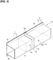
Figure 3 is a perspective view illustrating a state in which a plate member of the second member ofFigure 2 is joined to a bent member. -
Figure 4 is a perspective view illustrating a state in which foamable epoxies inside the first member and the second member receive heat and are foamed and integrated. -
Figure 5 is a side view illustrating an example in which the member joining method of the present invention is applied to a front pillar of an automobile as seen from the outside of the vehicle body. -
Figure 6 is a perspective view of the periphery of the front pillar ofFigure 5 as seen from the front of the vehicle body. -
Figure 7 is a perspective view of the periphery of the front pillar ofFigure 5 as seen from the inside of the vehicle body. -
Figure 8 is a cross-sectional view taken along line A-A inFigure 7 . -
Figure 9 is a cross-sectional view taken along line B-B inFigure 7 . -
Figure 10 is an assembly process view, illustrating a state in which foamable epoxy is disposed on a pillar base portion of the front pillar and on each outer member of a pillar body. -
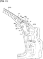
Figure 11 is an assembly process view, illustrating a state in which the pillar base portion and the outer members of the pillar body are joined to each other by means of welding from the state ofFigure 10 . -
Figure 12 is a side view illustrating each inner member that is joined to each outer member ofFigure 11 from the inner side of the vehicle. -
Figure 13 is an assembly process view, illustrating a state in which each inner member ofFigure 12 is joined to each outer member of the pillar body and the pillar base portion illustrated inFigure 11 by means of welding. - Embodiments for implementing the present invention are described in detail below with reference to the drawings.
- The
first member 1 and thesecond member 3 shown inFigure 1 are integrated by the end portions thereof being joined to each other, as illustrated inFigure 3 . Thefirst member 1 is made of metal and is composed of abent member 5 having a hat-shaped cross section, and arectangular plate member 7. Thebent member 5 has anopen portion 5a on one side surface, and forms a rectangular closedcross-sectional space 9 with theplate member 7 by welding and securing theplate member 7 so as to close theopen portion 5a. - In the same manner, the
second member 3 is also made of metal and is composed of abent member 11 having a hat-shaped cross section, and arectangular plate member 13. Thebent member 11 has anopen portion 11a on one side surface, and forms a rectangular closedcross-sectional space 15 with theplate member 13 by securing theplate member 13 by welding so as to close theopen portion 11a. - As illustrated in
Figure 1 , thefirst member 1 accommodates afoamable epoxy 17 prior to foaming as a first resin member adjacent an opening 9a corresponding to one end portion of the closedcross-sectional space 9 inside thebent member 5, before theplate member 7 is secured by welding to thebent member 5. Thefoamable epoxy 17 has a cross-sectional shape consisting of a cube or a rectangular parallelepiped equivalent to that of the closedcross-sectional space 9, and the outer surface thereof is substantially in close contact with the inner surfaces of thebent member 5 and theplate member 7. - A positioning hole 5b1 is formed on the
surface 5b on the opposite side of theopen portion 5a of thebent member 5. On the other hand, apositioning protrusion 17a is provided on a side of thefoamable epoxy 17 opposite theopen portion 5a. By pushing and inserting thefoamable epoxy 17 from theopen portion 5a of thebent member 5, theprotrusion 17a is inserted and positioned in the positioning hole 5b1. - Then,
flanges bent member 5 and theplate member 7 are joined and secured by welding. At this time, the opening 9a side end portions of thebent member 5 and theplate member 7 are in the same surface position, and these end portions and the end surface of thefoamable epoxy 17 are substantially matched to be in substantially the same surface position. - As illustrated in
Figure 1 , thebent member 11 of thesecond member 3 has an expandedportion 19 that is formed by bending an opening 15a side, corresponding to one end portion of the closedcross-sectional space 15 inside thebent member 11, so as to expand outward over the entire perimeter. The end portion of thefirst member 1 on the opening 9a side is inserted into the expandedportion 19, as illustrated inFigures 2 and3 . Theplate member 13 has abent portion 13a corresponding to the expandedportion 19, which is bent in a direction away from the expandedportion 19. - The
second member 3 accommodates afoamable epoxy 21 prior to foaming as a second resin member adjacent an opening 15a corresponding to one end portion of the closedcross-sectional space 15 inside thebent member 11, in a position interfering with the expandedportion 19, before theplate member 13 is joined and secured to thebent member 11. Thefoamable epoxy 21 has a cross-sectional shape consisting of a cube or a rectangular parallelepiped equivalent to that of the closedcross-sectional space 15, and the outer surface thereof is substantially in close contact with the inner surfaces of thebent member 11 and theplate member 13. - A positioning hole 11b1 is formed on the
surface 11b on the opposite side of theopen portion 11a of thebent member 11. On the other hand, apositioning protrusion 21a is provided on a side of thefoamable epoxy 21 opposite theopen portion 11a. By pushing and inserting thefoamable epoxy 21 from theopen portion 11a of thebent member 11, theprotrusion 21a is inserted and positioned in the positioning hole 11b1. - Then, the end portion of the
first member 1 on the side of the opening 9a is inserted and disposed inside the expandedportion 19 of thebent member 11, and secured by welding, as illustrated inFigure 2 . In as state in which the first member and thebent member 11 of thesecond member 3 are secured by welding as illustrated inFigure 2 , theflanges bent member 11 and theplate member 13 are joined and secured by welding, as illustrated inFigure 3 . At this time thebent portion 13a of theplate member 13 is positioned overlapping theplate member 7 in a position corresponding to the expandedportion 19, and then secured by welding. - In the state shown in
Figure 3 , agap 23 is formed between thefoamable epoxy 17 and thefoamable epoxy 21. In order to form thegap 23, thefoamable epoxy 21 is disposed at a position that is slightly separated from the expandedportion 19. - In the state shown in
Figure 3 , a joinedmember 25, which is obtained by welding and joining thefirst member 1 and thesecond member 3, is heated at the time of coating, for example, in a curing step, and thefoamable epoxies foamable epoxies gap 23, and, in due time, come into contact and adhere to each other. At this time thefoamable epoxies openings - Due to expansion at the time of foaming, the outer peripheral surfaces of the
foamable epoxies first member 1 and thesecond member 3.Figure 4 illustrates a joinedfoam 27 obtained when thefoamable epoxies member 25. - Thus, in a state in which the
first member 1 and thesecond member 3 are joined by means of welding, thefoamable epoxies cross-sectional spaces foam 27. Consequently, in addition to the joining force due to welding, the joining strength between thefirst member 1 and thesecond member 3 resulting from the member joining method described above is further improved by the joining force that is generated due to the integration of the resin. - In the present embodiment, the
foamable epoxies first member 1 and thesecond member 3, which are joined to each other. Accordingly, it is unnecessary to provide additional equipment such as a dedicated heating furnace, thus contributing to cost reduction. - Because the strength after curing is higher compared to other foam materials, such as foamable urethane,
foamable epoxy first member 1 and thesecond member 3. - The foamable epoxies 17, 21 expand smoothly due to foaming after heating, thanks to the
gap 23 provided therebetween, as illustrated inFigures 2 and3 . As a result, it becomes easy for thefoamable epoxies - In addition, by providing the
gap 23, it becomes possible to prevent thefoamable epoxies first member 1 and thesecond member 3, in the state shown inFigure 1 , are abutted to achieve the state shown inFigure 2 . Accordingly, it becomes easy to insert and dispose the end portion of thefirst member 1 in a specified position inside the expandedportion 19 of thesecond member 3, and to reliably join thefirst member 1 and thesecond member 3. - In the embodiment described above, when forming the
gap 23, thefoamable epoxy 21 is disposed in a position separated from the expandedportion 19. Alternatively, thefoamable epoxy 17 can be shifted from the end portion of thefirst member 1 on theopening 9a side so as to be positioned inside the closedcross-sectional space 9. - Additionally, with regard to the
second member 3 in the embodiment described above thebent member 11 is joined to thefirst member 1 before theplate member 13 is joined, as illustrated inFigure 2 . Alternatively, the end portion of thefirst member 1 can be inserted in a space surrounded by thebent portion 13a and the expandedportion 19 of thesecond member 3 and joined, after theplate member 13 has been joined to thebent member 11. Alternatively, thebent members plate members bent members plate members - The foamable epoxies 17, 21 can be inserted and disposed inside the
bent members bent members plate members bent members foamable epoxies cross-sectional spaces openings plate members bent members cross-sectional spaces positioning protrusions foamable epoxies first member 1 and thesecond member 3 by an adhesive. Positioningprotrusions -
Figures 5-7 illustrate a state in which the joinedmember 25 obtained by joining thefirst member 1 and thesecond member 3 shown inFigure 4 by means of welding is applied to a body member of an automobile, corresponding to a state after the joining ofFigure 4 . The body member here is afront pillar 31 of abody 29 of an automobile, and thefront pillar 31 includes a first member and a second member. In the figure, the direction indicated by the arrow FR is the front of the body, and the direction indicated by the arrow UP is the upper direction of the body.Figure 5 is a side view of the inner side of the vehicle as seen from the outside of the vehicle, andFigure 7 is a side view of the outside of the vehicle as seen from the inner side of the vehicle, in contrast withFigure 5 . - The
front pillar 31 includes apillar base portion 33 positioned on the lower front fender side, and apillar body 35 positioned on the upper roof side. Thefront pillar 31 is configured by joining the end portions of thepillar base portion 33 and thepillar body 35 to each other. Thefoamable epoxy 37 on thepillar base portion 33 side and thefoamable epoxy 39 on thepillar body 35 side are joined, in a state in which thepillar base portion 33 and thepillar body 35 are joined, to form a joinedfoam 41 that is similar to the joinedfoam 27 ofFigure 4 . Either one of thefoamable epoxies - The
pillar base portion 33 includes anouter member 43 on the vehicle exterior OUT side, and aninner member 45 on the vehicle interior IN side (dash side), as illustrated inFigure 8 , which is a cross-sectional view taken along line A-A inFigure 7 . When bent so as to protrude to the vehicle exterior OUT side, theouter member 43 forms a closedcross-sectional space 47 with theinner member 45. A reinforcingmember 49 is provided on the inner surface of a portion of theouter member 43 corresponding to the closedcross-sectional space 47. Thebracket 51 is joined and secured to theouter member 43 at thejoint portions Figures 10 and11 , which are described later, and is substantially in contact with the inner surface of theinner member 45, as illustrated inFigure 8 . Vehicle parts, which are disposed on the vehicle interior IN side, and which are not shown, are attached to thebracket 51. - A portion of the joined
foam 41 corresponding to thefoamable epoxy 37 after foaming is disposed in the closedcross-sectional space 47 illustrated inFigure 8 . InFigure 8 , a gap is formed between thefoamable epoxy 37 after foaming and the inner wall of the closedcross-sectional space 47, but actually there is almost no gap, and the epoxy and the inner wall are in close contact. - A positioning hole 53 is provided by forming through-
holes 43a and 49a in theouter member 43 and the reinforcingmember 49, respectively, as illustrated inFigure 8 . Apositioning protrusion 37a, which is inserted into the positioning hole 53, is provided on thefoamable epoxy 37. The through-hole 49a is smaller than the through-hole 43a, and when thepositioning protrusion 37a has been inserted into the positioning hole 53, the positioning protrusion is locked in the through-hole 49a, and is prevented from falling out. The lower positioning structure including thepositioning protrusion 37a and the positioning hole 53 is set in two locations adjacent the two end portions of thefoamable epoxy 37, in the longitudinal direction, as illustrated inFigure 5 . - The
pillar body 35 includes anouter member 55 on the vehicle exterior OUT side, and aninner member 57 on the vehicle interior IN side, as illustrated inFigure 9 , which is a cross-sectional view taken along line B-B inFigure 7 . When bent so as to protrude to the vehicle exterior OUT side, theouter member 55 forms a closedcross-sectional space 59 with theinner member 57. A portion of the joinedfoam 41 corresponding to thefoamable epoxy 39 after foaming is disposed in the closedcross-sectional space 59. InFigure 9 , a gap is formed between thefoamable epoxy 39 after foaming and the inner wall of the closedcross-sectional space 59, but actually there is almost no gap, and the epoxy and the inner wall are in close contact. - The
outer member 55 is provided with apositioning hole 55a, and thefoamable epoxy 39 is provided with apositioning protrusion 39a, as illustrated inFigure 5 . Thefoamable epoxy 39 is positioned on theouter member 55 by inserting thepositioning protrusion 39a into thepositioning hole 55a. The upper positioning structure including thepositioning protrusion 39a and thepositioning hole 55a is set in one location adjacent the end portion of thefoamable epoxy 39 on the far side from thefoamable epoxy 37. - Next, the assembly procedure will be described with reference to
Figures 10-13 . -
Figure 10 illustrates a state in which thefoamable epoxy 37 and thefoamable epoxy 39 before foaming are respectively disposed on theouter member 43 of thepillar base portion 33 and theouter member 55 of thepillar body 35. At this time, thepositioning protrusion 37a of thefoamable epoxy 37 is inserted into the positioning hole 53 and thepositioning protrusion 39a of thefoamable epoxy 39 is inserted into thepositioning hole 55a, to thereby position thefoamable epoxies Figure 8 . When carrying out the positioning described above, a portion of thefoamable epoxy 37 is covered and held from the vehicle interior IN side by an upper end portion of thebracket 51, as illustrated inFigure 10 . - When being positioned on the
outer member 43, thefoamable epoxy 37 is disposed in a position retracted inwardly from ajoint end portion 43b of theouter member 43, as illustrated inFigure 10 . Conversely, when being positioned on theouter member 55, thefoamable epoxy 39 is disposed in a position protruding outwardly from ajoint end portion 55b of theouter member 55. - The
foamable epoxy 37 is provided with a protrudingportion 37b at an end portion on thejoint end portion 43b side, which protrudes toward thejoint end portion 43b side on the lower side. On the other hand, thefoamable epoxy 39 is provided with a recessedportion 39b on the vehicle exterior OUT side on the lower side of an end portion on the side that protrudes outward. The protrudingportion 37b is inserted and disposed in the recessedportion 39b. - From the state shown in
Figure 10 , theouter member 43 of thepillar base portion 33 and theouter member 55 of thepillar body 35 are joined by means of welding, by bringing thejoint end portions Figure 11 . At this time, the respective end portions of theouter members outer member 43 of thepillar base portion 33 is positioned closer to the vehicle interior IN side (the front side of the page inFigure 11 ) than theouter member 55 of thepillar body 35. That is, theouter member 43 of thepillar base portion 33 is inserted between thefoamable epoxy 39 and theouter member 55 of thepillar body 35. - In a state in which the end portions of the
outer members portion 37b of thefoamable epoxy 37 is inserted and disposed in the recessedportion 39b of thefoamable epoxy 39, as illustrated inFigure 11 . When the protrudingportion 37b is inserted and disposed in the recessedportion 39b, a lower surface 39b1 of the recessedportion 39b rests on an upper surface 37b1 of the protrudingportion 37b. - Additionally, in the state shown in
Figure 11 a distal end surface 37b2 of the protrudingportion 37b is separated from a recess inner-end surface 39b2 of the recessedportion 39b, thus forming alower gap 61 therebetween. Furthermore, anend surface 39c of thefoamable epoxy 39 on the side that protrudes outward is separated from anend surface 37c of thefoamable epoxy 37, thus forming anupper gap 63 therebetween. - Because the foamable resin is provided with the positioning structures at two locations configured by the two
positioning protrusions 37a with respect to theouter member 43, the position of thefoamable epoxy 37 is substantially fixed, as illustrated inFigure 5 . However, by provided the positioning structure at one location configured by onepositioning protrusion 39a, on a side away from thefoamable epoxy 37, as illustrated inFigure 5 , it becomes possible for the foamable epoxy 39 to be somewhat swingably displaced in the vertical direction, with thepositioning protrusion 39a as the fulcrum. - As a result, the operation to place the lower surface 39b1 of the recessed
portion 39b of thefoamable epoxy 39 on the upper surface 37b1 of the protrudingportion 37b of thefoamable epoxy 37 becomes easy, when joining the end portions of theouter member 43 of thepillar base portion 33 and theouter member 55 of thepillar body 35 to each other. - Next, the
inner member 45 and theinner member 57 shown inFigure 12 are placed on theouter member 43 and theouter member 55, respectively, as shown inFigure 11 , so as to overlap each other, as illustrated inFigure 13 , and the abutting portions are joined to each other by means of welding. At this time, the end portion of theinner member 57 is closer to the front surface side of the page inFigure 13 (vehicle interior IN side) than the end portion of theinner member 45. As a result, the vehicle interior IN side of thefoamable epoxies inner members cross-sectional spaces cross-sectional spaces cross-sectional spaces - In the state shown in
Figure 13 thebody 29 including thefront pillar 31 is heated at the time of coating, for example, in a curing step, and thefoamable epoxies lower gap 61 and theupper gap 63, as illustrated inFigure 11 , and, in due time, come into contact and adhere to each other. At this time, thefoamable epoxies portion 37b and the recessedportion 39b, mix together and harden, thereby enabling joining and integration to form a joinedfoam 41. - Additionally, due to expansion at the time of foaming, the outer peripheral surfaces of the
foamable epoxies cross-sectional spaces - Thus, in a state in which the
pillar base portion 33 and thepillar body 35 of thefront pillar 31 are joined by means of welding, thefoamable epoxies cross-sectional spaces foam 41. Consequently, in addition to the joining force due to welding, the joining strength between thepillar base portion 33 and thepillar body 35 is further improved by the joining force that is generated due to the integration of the resin. - The first member and the second member whose end portions are joined to each other are included in the
front pillar 31 of the body member. In this case, by increasing the joining strength between thepillar base portion 33 and thepillar body 35 of thefront pillar 31, the crushing strength against a downward load received by the roof of the body from above is increased. - In the member joining method for joining the
pillar base portion 33 and thepillar body 35 of thefront pillar 31 described above, thefoamable epoxies outer members outer members inner members outer members foamable epoxies cross-sectional spaces outer members inner members foamable epoxies cross-sectional spaces - Embodiments of the present invention were described above, but these embodiments are described in order to facilitate understanding of the present invention, and the present invention is not limited to the embodiments. The technical scope of the present invention is not limited to the specific technical matters disclosed in the above-described embodiments, and includes various modifications, changes, and alternatives that can be easily derived therefrom.
- In the above-described embodiment, an example was described in which foamable epoxy is used as the first resin member and the second resin member, but the foam material is not limited to a foamable epoxy. For example, the foam material can be foamable urethane. In addition to a foam material, a resin member that is joined by means of heating and glass transition or melting can be used, for example nylon 66, which is a synthetic polyamide fiber.
- Since nylon 66 has flowability at the melting point, it becomes necessary to provide a flow stopping member for preventing outflow of molten resin on the opposite side of the joining surface of the two resin members.
- In the embodiment illustrated in
Figures 5-11 , the shapes of the end portions of thefoamable epoxies Figures 10 ,11 . For example, in the state shown inFigure 11 , thefoamable epoxies portion 37b and the recessedportion 39b. - The present invention is applied to a member joining method for joining members provided with closed cross-sectional spaces.
-
- 1
- First member
- 3
- Second member
- 9
- Closed cross-sectional space of first member
- 15
- Closed cross-sectional space of second member
- 17
- Foamable epoxy (first resin member)
- 21
- Foamable epoxy (second resin member)
- 31
- Front pillar
- 33
- Pillar base portion of front pillar
- 35
- Pillar body of front pillar
- 37, 39
- Foamable epoxy
- 43
- Outer member of pillar base portion
- 45
- Inner member of pillar base portion
- 47
- Closed cross-sectional space of pillar base portion
- 55
- Outer member of pillar body
- 57
- Inner member of pillar body
- 59
- Closed cross-sectional space of pillar body
Claims (4)
- A member joining method comprising:a step of arranging a first resin member inside a first member;a step of arranging a second resin member inside a second member;a step of joining respective end portions of the first member and the second member to each other; anda step of integrally joining the first resin member inside the first member and the second resin member inside the second member to join the first member and the second member by heat deformation to mix and cure areas adjacent the end portions thereof at a time of coating.
- The member joining method according to claim 1, wherein the first resin member and the second resin member are foamable epoxies that foam when heated.
- The member joining method according to claim 1 or 2, wherein the first member and the second member are included in a front pillar of an automobile.
- The member joining method according to claim 3, wherein
each of the first member and the second member includes an outer member and an inner member forming a closed cross-sectional space, and
the method further comprises: a step of arranging the first resin member on the outer member of the first member;
a step of arranging the second resin member on the outer member of the second member;
a step of joining end portions of the outer member of the first member on which the first resin member is disposed and the outer member of the second member on which the second resin member is disposed to each other;
a step of joining the inner member of the first member to the outer member of the first member so as to cover the first resin member;
a step of joining the inner member of the second member to the outer member of the second member so as to cover the second resin member; and
a step of integrally joining of the first resin member positioned in the closed cross-sectional space of the first member and the second resin member positioned in the closed cross-sectional space of the second member by applying heat to deform at a time of coating so as areas adjacent end portions thereof are mixed and cured.
Applications Claiming Priority (1)
| Application Number | Priority Date | Filing Date | Title |
|---|---|---|---|
| PCT/JP2016/063364 WO2017187602A1 (en) | 2016-04-28 | 2016-04-28 | Member joining method |
Publications (3)
| Publication Number | Publication Date |
|---|---|
| EP3450144A1 true EP3450144A1 (en) | 2019-03-06 |
| EP3450144A4 EP3450144A4 (en) | 2019-04-24 |
| EP3450144B1 EP3450144B1 (en) | 2020-06-03 |
Family
ID=60161418
Family Applications (1)
| Application Number | Title | Priority Date | Filing Date |
|---|---|---|---|
| EP16900472.8A Active EP3450144B1 (en) | 2016-04-28 | 2016-04-28 | Member joining method |
Country Status (5)
| Country | Link |
|---|---|
| US (1) | US10480556B1 (en) |
| EP (1) | EP3450144B1 (en) |
| JP (1) | JP6555415B2 (en) |
| CN (1) | CN109070492B (en) |
| WO (1) | WO2017187602A1 (en) |
Families Citing this family (3)
| Publication number | Priority date | Publication date | Assignee | Title |
|---|---|---|---|---|
| CN116833695B (en) * | 2022-03-23 | 2025-11-28 | 北京小米移动软件有限公司 | Fitting assembling device, fitting assembling method, fitting assembling device, terminal device and medium |
| CN116699781B (en) * | 2023-05-15 | 2024-01-30 | 北京创思工贸有限公司 | Processing method of optical glued piece |
| CN119820250A (en) * | 2023-10-13 | 2025-04-15 | 浙江极氪智能科技有限公司 | Processing method of foamed aluminum and car body cavity structure applying processing method |
Family Cites Families (19)
| Publication number | Priority date | Publication date | Assignee | Title |
|---|---|---|---|---|
| JPS6141537A (en) * | 1984-08-02 | 1986-02-27 | 日東電工株式会社 | Method of bonding metallic plate |
| JPS61116509A (en) | 1984-11-13 | 1986-06-04 | Toyota Motor Corp | Filling method of car body with foam |
| JPH02255883A (en) | 1988-09-21 | 1990-10-16 | Nitto Denko Corp | Spot-weldable adhesive sheet |
| US5213391A (en) * | 1990-10-25 | 1993-05-25 | Nissan Motor Co., Ltd. | Body skeleton element of vehicle and manufacturing method thereof |
| JP3954119B2 (en) * | 1995-01-21 | 2007-08-08 | イイダ産業株式会社 | Heated foam filling reinforcement and closed cross-section structural member reinforcement structure using the same heated foam filling reinforcement |
| JPH10181634A (en) | 1996-12-27 | 1998-07-07 | Nissan Motor Co Ltd | Box-shaped structural member for vehicle body with improved rigidity and method of manufacturing the same |
| JPH10203404A (en) | 1997-01-21 | 1998-08-04 | Nissan Motor Co Ltd | Method of improving rigidity of vehicle body of automobile and method of manufacturing box-shaped structural member of vehicle body |
| JPH10273069A (en) | 1997-03-31 | 1998-10-13 | Sunstar Eng Inc | Reinforcing method of vehicle body |
| US6247287B1 (en) * | 1998-08-05 | 2001-06-19 | Neo-Ex Lab, Inc. | Structure and method for closing and reinforcing hollow structural members |
| JP3428545B2 (en) * | 2000-01-07 | 2003-07-22 | 本田技研工業株式会社 | Body reinforcement structure |
| US6378933B1 (en) * | 2000-11-06 | 2002-04-30 | Daimlerchrysler Corporation | Reinforced vehicle framing |
| JP4052566B2 (en) * | 2002-09-05 | 2008-02-27 | 本田技研工業株式会社 | Frame coupling structure and coupling method |
| KR20050092021A (en) | 2002-12-27 | 2005-09-16 | 다우 글로벌 테크놀로지스 인크. | Heat activated epoxy adhesive and use in a structural foam insert |
| DE102004016134A1 (en) * | 2004-04-01 | 2005-11-03 | Bayerische Motoren Werke Ag | Motor vehicle with a roof |
| TWI353303B (en) * | 2004-09-07 | 2011-12-01 | Toray Industries | Sandwich structure and integrated molding using th |
| JP4545079B2 (en) | 2005-10-19 | 2010-09-15 | トヨタ自動車株式会社 | Laser welding method and laser welding apparatus for thermoplastic resin member |
| DE102007038659A1 (en) * | 2007-08-15 | 2009-02-19 | Henkel Ag & Co. Kgaa | Expandable filler insert for filling hollow spaces, comprises self-supporting continuous structure including polymer matrix containing polymer(s) or polymer precursor and latent blowing agent(s), and spacer and/or fixing element |
| US20080296164A1 (en) * | 2007-06-02 | 2008-12-04 | Lanxess Deutschland Gmbh | Reinforcement Element for a Vehicle Hollow Body |
| JP6010641B2 (en) | 2015-01-28 | 2016-10-19 | 富士重工業株式会社 | Resin member and joining method of resin member |
-
2016
- 2016-04-28 CN CN201680084566.4A patent/CN109070492B/en active Active
- 2016-04-28 JP JP2018514056A patent/JP6555415B2/en active Active
- 2016-04-28 US US16/089,413 patent/US10480556B1/en active Active
- 2016-04-28 EP EP16900472.8A patent/EP3450144B1/en active Active
- 2016-04-28 WO PCT/JP2016/063364 patent/WO2017187602A1/en not_active Ceased
Also Published As
| Publication number | Publication date |
|---|---|
| JP6555415B2 (en) | 2019-08-07 |
| EP3450144B1 (en) | 2020-06-03 |
| WO2017187602A1 (en) | 2017-11-02 |
| CN109070492A (en) | 2018-12-21 |
| US20190338795A1 (en) | 2019-11-07 |
| CN109070492B (en) | 2020-07-03 |
| EP3450144A4 (en) | 2019-04-24 |
| JPWO2017187602A1 (en) | 2019-03-07 |
| US10480556B1 (en) | 2019-11-19 |
Similar Documents
| Publication | Publication Date | Title |
|---|---|---|
| US6896320B2 (en) | Reinforced structural body | |
| EP1731284B1 (en) | Noise reduction member and system | |
| US9688125B2 (en) | Vehicle back door assembling method and vehicle back door | |
| JPH02175475A (en) | Resin filling and reinforcing method for car body structure member and dam structure of filling resin | |
| EP3450144B1 (en) | Member joining method | |
| US8366181B2 (en) | Structural reinforcer applied to cut-out area of structural member | |
| KR20090048574A (en) | Structural reinforcement | |
| CA2419843A1 (en) | Lightweight constructional element with external ribbing | |
| EP4678513A2 (en) | Reinforcement devices | |
| CN102470734A (en) | Reinforced door frame construction for vehicle | |
| CN106004765A (en) | Method for manufacturing a vehicle interior trim part intended for covering an airbag | |
| US12304562B2 (en) | Hollow chamber support assembly for a vehicle | |
| JP2003226261A (en) | Reinforcement structure and method for hollow structure | |
| JP4916019B2 (en) | Vibration welding structure of resin molded products | |
| EP3805078B1 (en) | Vehicle body structure and method for manufacturing vehicle body | |
| JP2003040138A (en) | Structure of foaming and filling hollow panel and its foaming and filling tool | |
| CN101909975A (en) | vehicle coupler | |
| KR970706990A (en) | INTERIOR TRIM COMPONENT FOR MOTOR VEHICLES | |
| JP4064341B2 (en) | Hot air shielding structure | |
| JPH04110280A (en) | Fixation of formed member in closed sectional surface part | |
| WO2011131334A1 (en) | Improvements in or relating to automobile components | |
| US20070200047A1 (en) | Expandable reinforcing member | |
| JPH07117713A (en) | Body structure reinforced by foam filling and method of reinforcing the body | |
| CN113165698A (en) | Reinforcement with integrated stop | |
| JP7359606B2 (en) | Vehicle panel structure and its manufacturing method |
Legal Events
| Date | Code | Title | Description |
|---|---|---|---|
| STAA | Information on the status of an ep patent application or granted ep patent |
Free format text: STATUS: THE INTERNATIONAL PUBLICATION HAS BEEN MADE |
|
| PUAI | Public reference made under article 153(3) epc to a published international application that has entered the european phase |
Free format text: ORIGINAL CODE: 0009012 |
|
| STAA | Information on the status of an ep patent application or granted ep patent |
Free format text: STATUS: REQUEST FOR EXAMINATION WAS MADE |
|
| 17P | Request for examination filed |
Effective date: 20181119 |
|
| AK | Designated contracting states |
Kind code of ref document: A1 Designated state(s): AL AT BE BG CH CY CZ DE DK EE ES FI FR GB GR HR HU IE IS IT LI LT LU LV MC MK MT NL NO PL PT RO RS SE SI SK SM TR |
|
| AX | Request for extension of the european patent |
Extension state: BA ME |
|
| A4 | Supplementary search report drawn up and despatched |
Effective date: 20190325 |
|
| RIC1 | Information provided on ipc code assigned before grant |
Ipc: B62D 29/00 20060101ALI20190319BHEP Ipc: B29C 69/00 20060101ALI20190319BHEP Ipc: B62D 25/04 20060101AFI20190319BHEP Ipc: B29C 65/02 20060101ALI20190319BHEP |
|
| DAV | Request for validation of the european patent (deleted) | ||
| DAX | Request for extension of the european patent (deleted) | ||
| REG | Reference to a national code |
Ref country code: DE Ref legal event code: R079 Ref document number: 602016037750 Country of ref document: DE Free format text: PREVIOUS MAIN CLASS: B29C0069000000 Ipc: B62D0025040000 |
|
| GRAP | Despatch of communication of intention to grant a patent |
Free format text: ORIGINAL CODE: EPIDOSNIGR1 |
|
| STAA | Information on the status of an ep patent application or granted ep patent |
Free format text: STATUS: GRANT OF PATENT IS INTENDED |
|
| RIC1 | Information provided on ipc code assigned before grant |
Ipc: B62D 29/00 20060101ALI20200130BHEP Ipc: B62D 25/04 20060101AFI20200130BHEP Ipc: B29C 65/02 20060101ALI20200130BHEP Ipc: B29C 69/00 20060101ALI20200130BHEP |
|
| INTG | Intention to grant announced |
Effective date: 20200226 |
|
| GRAS | Grant fee paid |
Free format text: ORIGINAL CODE: EPIDOSNIGR3 |
|
| GRAA | (expected) grant |
Free format text: ORIGINAL CODE: 0009210 |
|
| STAA | Information on the status of an ep patent application or granted ep patent |
Free format text: STATUS: THE PATENT HAS BEEN GRANTED |
|
| AK | Designated contracting states |
Kind code of ref document: B1 Designated state(s): AL AT BE BG CH CY CZ DE DK EE ES FI FR GB GR HR HU IE IS IT LI LT LU LV MC MK MT NL NO PL PT RO RS SE SI SK SM TR |
|
| REG | Reference to a national code |
Ref country code: GB Ref legal event code: FG4D |
|
| REG | Reference to a national code |
Ref country code: CH Ref legal event code: EP Ref country code: AT Ref legal event code: REF Ref document number: 1276731 Country of ref document: AT Kind code of ref document: T Effective date: 20200615 |
|
| REG | Reference to a national code |
Ref country code: DE Ref legal event code: R096 Ref document number: 602016037750 Country of ref document: DE |
|
| REG | Reference to a national code |
Ref country code: LT Ref legal event code: MG4D |
|
| PG25 | Lapsed in a contracting state [announced via postgrant information from national office to epo] |
Ref country code: NO Free format text: LAPSE BECAUSE OF FAILURE TO SUBMIT A TRANSLATION OF THE DESCRIPTION OR TO PAY THE FEE WITHIN THE PRESCRIBED TIME-LIMIT Effective date: 20200903 Ref country code: GR Free format text: LAPSE BECAUSE OF FAILURE TO SUBMIT A TRANSLATION OF THE DESCRIPTION OR TO PAY THE FEE WITHIN THE PRESCRIBED TIME-LIMIT Effective date: 20200904 Ref country code: FI Free format text: LAPSE BECAUSE OF FAILURE TO SUBMIT A TRANSLATION OF THE DESCRIPTION OR TO PAY THE FEE WITHIN THE PRESCRIBED TIME-LIMIT Effective date: 20200603 Ref country code: SE Free format text: LAPSE BECAUSE OF FAILURE TO SUBMIT A TRANSLATION OF THE DESCRIPTION OR TO PAY THE FEE WITHIN THE PRESCRIBED TIME-LIMIT Effective date: 20200603 Ref country code: LT Free format text: LAPSE BECAUSE OF FAILURE TO SUBMIT A TRANSLATION OF THE DESCRIPTION OR TO PAY THE FEE WITHIN THE PRESCRIBED TIME-LIMIT Effective date: 20200603 |
|
| REG | Reference to a national code |
Ref country code: NL Ref legal event code: MP Effective date: 20200603 |
|
| PG25 | Lapsed in a contracting state [announced via postgrant information from national office to epo] |
Ref country code: BG Free format text: LAPSE BECAUSE OF FAILURE TO SUBMIT A TRANSLATION OF THE DESCRIPTION OR TO PAY THE FEE WITHIN THE PRESCRIBED TIME-LIMIT Effective date: 20200903 Ref country code: RS Free format text: LAPSE BECAUSE OF FAILURE TO SUBMIT A TRANSLATION OF THE DESCRIPTION OR TO PAY THE FEE WITHIN THE PRESCRIBED TIME-LIMIT Effective date: 20200603 Ref country code: LV Free format text: LAPSE BECAUSE OF FAILURE TO SUBMIT A TRANSLATION OF THE DESCRIPTION OR TO PAY THE FEE WITHIN THE PRESCRIBED TIME-LIMIT Effective date: 20200603 Ref country code: HR Free format text: LAPSE BECAUSE OF FAILURE TO SUBMIT A TRANSLATION OF THE DESCRIPTION OR TO PAY THE FEE WITHIN THE PRESCRIBED TIME-LIMIT Effective date: 20200603 |
|
| REG | Reference to a national code |
Ref country code: AT Ref legal event code: MK05 Ref document number: 1276731 Country of ref document: AT Kind code of ref document: T Effective date: 20200603 |
|
| PG25 | Lapsed in a contracting state [announced via postgrant information from national office to epo] |
Ref country code: NL Free format text: LAPSE BECAUSE OF FAILURE TO SUBMIT A TRANSLATION OF THE DESCRIPTION OR TO PAY THE FEE WITHIN THE PRESCRIBED TIME-LIMIT Effective date: 20200603 Ref country code: AL Free format text: LAPSE BECAUSE OF FAILURE TO SUBMIT A TRANSLATION OF THE DESCRIPTION OR TO PAY THE FEE WITHIN THE PRESCRIBED TIME-LIMIT Effective date: 20200603 |
|
| PG25 | Lapsed in a contracting state [announced via postgrant information from national office to epo] |
Ref country code: AT Free format text: LAPSE BECAUSE OF FAILURE TO SUBMIT A TRANSLATION OF THE DESCRIPTION OR TO PAY THE FEE WITHIN THE PRESCRIBED TIME-LIMIT Effective date: 20200603 Ref country code: EE Free format text: LAPSE BECAUSE OF FAILURE TO SUBMIT A TRANSLATION OF THE DESCRIPTION OR TO PAY THE FEE WITHIN THE PRESCRIBED TIME-LIMIT Effective date: 20200603 Ref country code: SM Free format text: LAPSE BECAUSE OF FAILURE TO SUBMIT A TRANSLATION OF THE DESCRIPTION OR TO PAY THE FEE WITHIN THE PRESCRIBED TIME-LIMIT Effective date: 20200603 Ref country code: RO Free format text: LAPSE BECAUSE OF FAILURE TO SUBMIT A TRANSLATION OF THE DESCRIPTION OR TO PAY THE FEE WITHIN THE PRESCRIBED TIME-LIMIT Effective date: 20200603 Ref country code: IT Free format text: LAPSE BECAUSE OF FAILURE TO SUBMIT A TRANSLATION OF THE DESCRIPTION OR TO PAY THE FEE WITHIN THE PRESCRIBED TIME-LIMIT Effective date: 20200603 Ref country code: PT Free format text: LAPSE BECAUSE OF FAILURE TO SUBMIT A TRANSLATION OF THE DESCRIPTION OR TO PAY THE FEE WITHIN THE PRESCRIBED TIME-LIMIT Effective date: 20201006 Ref country code: CZ Free format text: LAPSE BECAUSE OF FAILURE TO SUBMIT A TRANSLATION OF THE DESCRIPTION OR TO PAY THE FEE WITHIN THE PRESCRIBED TIME-LIMIT Effective date: 20200603 Ref country code: ES Free format text: LAPSE BECAUSE OF FAILURE TO SUBMIT A TRANSLATION OF THE DESCRIPTION OR TO PAY THE FEE WITHIN THE PRESCRIBED TIME-LIMIT Effective date: 20200603 |
|
| PG25 | Lapsed in a contracting state [announced via postgrant information from national office to epo] |
Ref country code: PL Free format text: LAPSE BECAUSE OF FAILURE TO SUBMIT A TRANSLATION OF THE DESCRIPTION OR TO PAY THE FEE WITHIN THE PRESCRIBED TIME-LIMIT Effective date: 20200603 Ref country code: SK Free format text: LAPSE BECAUSE OF FAILURE TO SUBMIT A TRANSLATION OF THE DESCRIPTION OR TO PAY THE FEE WITHIN THE PRESCRIBED TIME-LIMIT Effective date: 20200603 Ref country code: IS Free format text: LAPSE BECAUSE OF FAILURE TO SUBMIT A TRANSLATION OF THE DESCRIPTION OR TO PAY THE FEE WITHIN THE PRESCRIBED TIME-LIMIT Effective date: 20201003 |
|
| REG | Reference to a national code |
Ref country code: DE Ref legal event code: R097 Ref document number: 602016037750 Country of ref document: DE |
|
| PLBE | No opposition filed within time limit |
Free format text: ORIGINAL CODE: 0009261 |
|
| STAA | Information on the status of an ep patent application or granted ep patent |
Free format text: STATUS: NO OPPOSITION FILED WITHIN TIME LIMIT |
|
| PG25 | Lapsed in a contracting state [announced via postgrant information from national office to epo] |
Ref country code: DK Free format text: LAPSE BECAUSE OF FAILURE TO SUBMIT A TRANSLATION OF THE DESCRIPTION OR TO PAY THE FEE WITHIN THE PRESCRIBED TIME-LIMIT Effective date: 20200603 |
|
| 26N | No opposition filed |
Effective date: 20210304 |
|
| PG25 | Lapsed in a contracting state [announced via postgrant information from national office to epo] |
Ref country code: SI Free format text: LAPSE BECAUSE OF FAILURE TO SUBMIT A TRANSLATION OF THE DESCRIPTION OR TO PAY THE FEE WITHIN THE PRESCRIBED TIME-LIMIT Effective date: 20200603 |
|
| PG25 | Lapsed in a contracting state [announced via postgrant information from national office to epo] |
Ref country code: MC Free format text: LAPSE BECAUSE OF FAILURE TO SUBMIT A TRANSLATION OF THE DESCRIPTION OR TO PAY THE FEE WITHIN THE PRESCRIBED TIME-LIMIT Effective date: 20200603 |
|
| PG25 | Lapsed in a contracting state [announced via postgrant information from national office to epo] |
Ref country code: LU Free format text: LAPSE BECAUSE OF NON-PAYMENT OF DUE FEES Effective date: 20210428 |
|
| REG | Reference to a national code |
Ref country code: BE Ref legal event code: MM Effective date: 20210430 |
|
| PG25 | Lapsed in a contracting state [announced via postgrant information from national office to epo] |
Ref country code: LI Free format text: LAPSE BECAUSE OF NON-PAYMENT OF DUE FEES Effective date: 20210430 Ref country code: CH Free format text: LAPSE BECAUSE OF NON-PAYMENT OF DUE FEES Effective date: 20210430 |
|
| PG25 | Lapsed in a contracting state [announced via postgrant information from national office to epo] |
Ref country code: IE Free format text: LAPSE BECAUSE OF NON-PAYMENT OF DUE FEES Effective date: 20210428 |
|
| PG25 | Lapsed in a contracting state [announced via postgrant information from national office to epo] |
Ref country code: IS Free format text: LAPSE BECAUSE OF FAILURE TO SUBMIT A TRANSLATION OF THE DESCRIPTION OR TO PAY THE FEE WITHIN THE PRESCRIBED TIME-LIMIT Effective date: 20201003 |
|
| PG25 | Lapsed in a contracting state [announced via postgrant information from national office to epo] |
Ref country code: BE Free format text: LAPSE BECAUSE OF NON-PAYMENT OF DUE FEES Effective date: 20210430 |
|
| PG25 | Lapsed in a contracting state [announced via postgrant information from national office to epo] |
Ref country code: CY Free format text: LAPSE BECAUSE OF FAILURE TO SUBMIT A TRANSLATION OF THE DESCRIPTION OR TO PAY THE FEE WITHIN THE PRESCRIBED TIME-LIMIT Effective date: 20200603 |
|
| PG25 | Lapsed in a contracting state [announced via postgrant information from national office to epo] |
Ref country code: HU Free format text: LAPSE BECAUSE OF FAILURE TO SUBMIT A TRANSLATION OF THE DESCRIPTION OR TO PAY THE FEE WITHIN THE PRESCRIBED TIME-LIMIT; INVALID AB INITIO Effective date: 20160428 |
|
| REG | Reference to a national code |
Ref country code: DE Ref legal event code: R084 Ref document number: 602016037750 Country of ref document: DE |
|
| REG | Reference to a national code |
Ref country code: GB Ref legal event code: 746 Effective date: 20230925 |
|
| PG25 | Lapsed in a contracting state [announced via postgrant information from national office to epo] |
Ref country code: MK Free format text: LAPSE BECAUSE OF FAILURE TO SUBMIT A TRANSLATION OF THE DESCRIPTION OR TO PAY THE FEE WITHIN THE PRESCRIBED TIME-LIMIT Effective date: 20200603 |
|
| PG25 | Lapsed in a contracting state [announced via postgrant information from national office to epo] |
Ref country code: TR Free format text: LAPSE BECAUSE OF FAILURE TO SUBMIT A TRANSLATION OF THE DESCRIPTION OR TO PAY THE FEE WITHIN THE PRESCRIBED TIME-LIMIT Effective date: 20200603 |
|
| PG25 | Lapsed in a contracting state [announced via postgrant information from national office to epo] |
Ref country code: MT Free format text: LAPSE BECAUSE OF FAILURE TO SUBMIT A TRANSLATION OF THE DESCRIPTION OR TO PAY THE FEE WITHIN THE PRESCRIBED TIME-LIMIT Effective date: 20200603 |
|
| PGFP | Annual fee paid to national office [announced via postgrant information from national office to epo] |
Ref country code: DE Payment date: 20250319 Year of fee payment: 10 |
|
| PGFP | Annual fee paid to national office [announced via postgrant information from national office to epo] |
Ref country code: GB Payment date: 20260319 Year of fee payment: 11 |
|
| PGFP | Annual fee paid to national office [announced via postgrant information from national office to epo] |
Ref country code: FR Payment date: 20260319 Year of fee payment: 11 |