EP3450122B1 - Station for cutting aa-type, d-type and/or c-type batteries, method for separating and recovering components of said batteries and system for implementing such a method - Google Patents
Station for cutting aa-type, d-type and/or c-type batteries, method for separating and recovering components of said batteries and system for implementing such a method Download PDFInfo
- Publication number
- EP3450122B1 EP3450122B1 EP17189197.1A EP17189197A EP3450122B1 EP 3450122 B1 EP3450122 B1 EP 3450122B1 EP 17189197 A EP17189197 A EP 17189197A EP 3450122 B1 EP3450122 B1 EP 3450122B1
- Authority
- EP
- European Patent Office
- Prior art keywords
- battery
- fraction
- cutting
- fragments
- station
- Prior art date
- Legal status (The legal status is an assumption and is not a legal conclusion. Google has not performed a legal analysis and makes no representation as to the accuracy of the status listed.)
- Not-in-force
Links
Images




Classifications
-
- B—PERFORMING OPERATIONS; TRANSPORTING
- B26—HAND CUTTING TOOLS; CUTTING; SEVERING
- B26D—CUTTING; DETAILS COMMON TO MACHINES FOR PERFORATING, PUNCHING, CUTTING-OUT, STAMPING-OUT OR SEVERING
- B26D3/00—Cutting work characterised by the nature of the cut made; Apparatus therefor
- B26D3/30—Halving devices, e.g. for halving buns
-
- B—PERFORMING OPERATIONS; TRANSPORTING
- B07—SEPARATING SOLIDS FROM SOLIDS; SORTING
- B07B—SEPARATING SOLIDS FROM SOLIDS BY SIEVING, SCREENING, SIFTING OR BY USING GAS CURRENTS; SEPARATING BY OTHER DRY METHODS APPLICABLE TO BULK MATERIAL, e.g. LOOSE ARTICLES FIT TO BE HANDLED LIKE BULK MATERIAL
- B07B9/00—Combinations of apparatus for screening or sifting or for separating solids from solids using gas currents; General arrangement of plant, e.g. flow sheets
-
- B—PERFORMING OPERATIONS; TRANSPORTING
- B26—HAND CUTTING TOOLS; CUTTING; SEVERING
- B26D—CUTTING; DETAILS COMMON TO MACHINES FOR PERFORATING, PUNCHING, CUTTING-OUT, STAMPING-OUT OR SEVERING
- B26D1/00—Cutting through work characterised by the nature or movement of the cutting member or particular materials not otherwise provided for; Apparatus or machines therefor; Cutting members therefor
- B26D1/0006—Cutting members therefor
-
- B—PERFORMING OPERATIONS; TRANSPORTING
- B26—HAND CUTTING TOOLS; CUTTING; SEVERING
- B26D—CUTTING; DETAILS COMMON TO MACHINES FOR PERFORATING, PUNCHING, CUTTING-OUT, STAMPING-OUT OR SEVERING
- B26D1/00—Cutting through work characterised by the nature or movement of the cutting member or particular materials not otherwise provided for; Apparatus or machines therefor; Cutting members therefor
- B26D1/01—Cutting through work characterised by the nature or movement of the cutting member or particular materials not otherwise provided for; Apparatus or machines therefor; Cutting members therefor involving a cutting member which does not travel with the work
- B26D1/02—Cutting through work characterised by the nature or movement of the cutting member or particular materials not otherwise provided for; Apparatus or machines therefor; Cutting members therefor involving a cutting member which does not travel with the work having a stationary cutting member
-
- B—PERFORMING OPERATIONS; TRANSPORTING
- B26—HAND CUTTING TOOLS; CUTTING; SEVERING
- B26D—CUTTING; DETAILS COMMON TO MACHINES FOR PERFORATING, PUNCHING, CUTTING-OUT, STAMPING-OUT OR SEVERING
- B26D3/00—Cutting work characterised by the nature of the cut made; Apparatus therefor
- B26D3/001—Cutting tubes longitudinally
-
- B—PERFORMING OPERATIONS; TRANSPORTING
- B26—HAND CUTTING TOOLS; CUTTING; SEVERING
- B26D—CUTTING; DETAILS COMMON TO MACHINES FOR PERFORATING, PUNCHING, CUTTING-OUT, STAMPING-OUT OR SEVERING
- B26D7/00—Details of apparatus for cutting, cutting-out, stamping-out, punching, perforating, or severing by means other than cutting
- B26D7/06—Arrangements for feeding or delivering work of other than sheet, web, or filamentary form
- B26D7/0625—Arrangements for feeding or delivering work of other than sheet, web, or filamentary form by endless conveyors, e.g. belts
-
- H—ELECTRICITY
- H01—ELECTRIC ELEMENTS
- H01M—PROCESSES OR MEANS, e.g. BATTERIES, FOR THE DIRECT CONVERSION OF CHEMICAL ENERGY INTO ELECTRICAL ENERGY
- H01M6/00—Primary cells; Manufacture thereof
- H01M6/02—Details
-
- H—ELECTRICITY
- H01—ELECTRIC ELEMENTS
- H01M—PROCESSES OR MEANS, e.g. BATTERIES, FOR THE DIRECT CONVERSION OF CHEMICAL ENERGY INTO ELECTRICAL ENERGY
- H01M6/00—Primary cells; Manufacture thereof
- H01M6/04—Cells with aqueous electrolyte
- H01M6/06—Dry cells, i.e. cells wherein the electrolyte is rendered non-fluid
-
- H—ELECTRICITY
- H01—ELECTRIC ELEMENTS
- H01M—PROCESSES OR MEANS, e.g. BATTERIES, FOR THE DIRECT CONVERSION OF CHEMICAL ENERGY INTO ELECTRICAL ENERGY
- H01M6/00—Primary cells; Manufacture thereof
- H01M6/52—Reclaiming serviceable parts of waste cells or batteries, e.g. recycling
-
- B—PERFORMING OPERATIONS; TRANSPORTING
- B26—HAND CUTTING TOOLS; CUTTING; SEVERING
- B26D—CUTTING; DETAILS COMMON TO MACHINES FOR PERFORATING, PUNCHING, CUTTING-OUT, STAMPING-OUT OR SEVERING
- B26D1/00—Cutting through work characterised by the nature or movement of the cutting member or particular materials not otherwise provided for; Apparatus or machines therefor; Cutting members therefor
- B26D1/0006—Cutting members therefor
- B26D2001/006—Cutting members therefor the cutting blade having a special shape, e.g. a special outline, serrations
-
- Y—GENERAL TAGGING OF NEW TECHNOLOGICAL DEVELOPMENTS; GENERAL TAGGING OF CROSS-SECTIONAL TECHNOLOGIES SPANNING OVER SEVERAL SECTIONS OF THE IPC; TECHNICAL SUBJECTS COVERED BY FORMER USPC CROSS-REFERENCE ART COLLECTIONS [XRACs] AND DIGESTS
- Y02—TECHNOLOGIES OR APPLICATIONS FOR MITIGATION OR ADAPTATION AGAINST CLIMATE CHANGE
- Y02W—CLIMATE CHANGE MITIGATION TECHNOLOGIES RELATED TO WASTEWATER TREATMENT OR WASTE MANAGEMENT
- Y02W30/00—Technologies for solid waste management
- Y02W30/50—Reuse, recycling or recovery technologies
- Y02W30/84—Recycling of batteries or fuel cells
Definitions
- the present invention relates to the field of plants and methods for the disposal and recovery of constituent components of alkaline-type and zinc-carbon-type batteries.
- the present invention relates to a cutting station for cutting AA-type and/or D-type or C-type batteries and to a method for the dry separation and the recovery of the components of said batteries.
- the invention further relates to a system for implementing such a method.
- These discreet current sources mainly consist of primary batteries and secondary batteries, or accumulators.
- Secondary batteries are instead rechargeable accumulators (e.g. the very common lithium batteries).
- alkaline batteries Although there are many types of batteries based on different oxide-reduction processes, the vast majority of them (nearly 90% of the market) are of the zinc-carbon and of the alkaline type, which is an evolution of the zinc-carbon battery; in particular, alkaline batteries currently account for about 75-80% of the market, while zinc-carbon batteries account for 10-15%. These batteries are used in applications such as electric torches, toys, electrical instruments and miscellaneous electronics.
- the generation of the electron flow is determined by a reduction reaction of manganese dioxide (IV), MnO 2 , and concurrent oxidation of the metal zinc ion Zn 2+ .
- the zinc (anode) forms the base and the cylindrical wall of the casing, while the manganese dioxide is immersed in a gelatinous paste also comprising ammonium chloride and carbon powder.
- the zinc is instead present in the form of power around an anode consisting of a metal bar; Zn and MnO 2 powders are immersed in a gelatinous paste of potassium hydroxide (KOH), which acts as an electrolyte and from which the name "alkaline” of these batteries derives.
- KOH potassium hydroxide
- the paste present in these batteries is also called “black paste” in the sector.
- Zn-C batteries and alkaline batteries The recovery and recycling of the components of zinc-carbon (hereinafter also indicated as Zn-C) batteries and alkaline batteries is the subject of very many studies and publications.
- the recycling procedures of the batteries imply a series of operations.
- the batteries must be separated by type.
- the first separation is of dimensional type and allows a first, very coarse, separation of the batteries according to the chemical component type, because the smaller batteries are not generally of the Zn-C or alkaline type; for example, they may be silver or mercury batteries, although the latter type has been nearly entirely phased out following the introduction of standards in most countries.
- This first separation may consist of a simple passage on vibrating belts or tables with openings of appropriate sizes increasing along the direction of transport of the batteries.
- a second separation is more specifically related to the chemical type of the batteries. This type of separation may occur as a function of their density, as described for example in international patent application WO 00/08700 A1 .
- the most common method is however based on X-ray imaging techniques which recognize the structure inside the battery (e.g. the arrangement of the electrodes, which may vary according to the battery type), as described, for example, in patents EP 795919 B1 and EP 1132992 B1 ; some recycling systems also include a manual separation, performed by human operators, for the batteries that the automated systems cannot safely assign to a specific type.
- the black paste components must be extracted from them.
- the batteries are grinded in some cases, or alternatively they may be opened in mechanized cutting stations; then, the particulate obtained from the grinding or the parts obtained by cutting are either washed or immersed in water or in aqueous based solutions, which leads to the dissolution or suspension of the black paste components in the liquid phase.
- the components which are not part of the black paste such as the steel which forms the battery casing or the plastic materials which form the lining or seals thereof, must be separated from the solution.
- the materials are washed in various manners to detach the black paste residues.
- the liquid phase thus obtained, containing the black paste components in solution or suspension, must then be subjected to chemical recovery processes of said components, in the same form in which they were present in the black paste or after appropriate chemical transformations, into a more manageable or useful form to be sent to the successive steps of recycling or direct reuse.
- the cutting of the batteries by means of mechanized stations promotes the separation of the black paste from the metal part and from the plastic part, because the cut parts have larger sizes than the grinded products.
- the batteries are cut by means of a steel blade which is preventively subjected to specific thermal treatments for its hardness and durability. Such treatments are established as a function of the materials which form the batteries.
- cutting blades are used with straight cutting edge which is developed along a reference direction which, during the step of cutting, is orthogonal to the axis of the battery.
- the methods currently used for separating and recovering the parts which form a battery include one or more steps of washing and/or one or more passes in treatment tank. Such methods thus have strong limits in terms of eco-sustainability.
- FR-1 082 614 A defines the preamble of claim 1.
- the main task of the present invention is to provide a new station for cutting a battery and a new method for separating and recovering the constituent parts of the battery itself.
- the present invention thus relates to a cutting station for cutting cylindrical batteries, i.e. batteries which have a substantially cylindrical body, which develops about a central axis between a first surface and second surface, which is transversal to said central axis.
- the cutting station comprises a substantially two-dimensional cutting blade, which identifies a cutting plane and a positioning device, which defines a seat for a battery to be cut, so that the central axis of the battery is substantially coplanar with the cutting plane identified by the two-dimensional blade.
- the cutting station further comprises pushing and moving means which determine a relative motion between the blade and the battery to be cut, along a direction of advancement parallel to the cutting plane. Following such a relative motion, the battery is cut into two halves by the blade.
- the blade comprises a cutting edge which defines at least one V-shaped notch.
- a notch faces one of the transversal surfaces of the battery when it is housed in the aforesaid seat and during the relative motion determined by the pushing and moving means.
- the battery impacts, at least partially, against the V-shaped notch following the relative motion determined by the pushing and moving means.
- the present invention also relates to a method for the dry separation of the components of cylindrical type batteries. More precisely, such a method has the purpose of separating the inner black paste from the metal part and from the plastic part present in the structure of the batteries.
- the method according to the invention is characterized in that it comprises at least the following steps:
- the method according to the invention allows to recover the black paste contained in the batteries without any passage in washing stations, with huge advantages in terms of eco-sustainability.
- nearly all the black paste is recovered by means of a relatively low number of steps which can be easily performed at absolutely competitive costs with respect to the traditional processes which include the use of washing stations and/or treatment baths.
- the present invention further relates to a system for implementing the method shown above.
- a cutting station for cutting a pelight type and/or a flashlight and/or a R14-type battery 2.
- a battery of each type has a substantially cylindrical body, which develops about a central axis 100 between a first transversal surface and a second transversal surface opposite to the first transversal surface.
- Such surfaces are substantially “transversal" to the central axis 100 of the battery 2 and correspond to the surfaces on which the electrodes for the operation of the battery itself are defined.
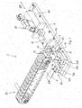
- the cutting station 1 comprises a cutting device 50 provided with a blade 5 through which the cutting of the battery 2 is achieved.
- the blade 5 displays a substantially two-dimensional conformation which identifies a cutting plane 200. Substantially, the blade 5 develops between two parallel planes, the distance of which corresponds to the thickness S 1 of the blade itself. Given the two-dimensional configuration, such a thickness is thus much lower than the other sizes of the blade.
- the cutting station 1 further comprises a positioning device 60 which defines a seat 61 for the battery 2.
- the blade 61 is shaped so that the central axis 100 of the battery 2 is substantially coplanar with the cutting plane 200 and one of the two transversal surfaces faces the blade 5.
- the cutting station 1 further comprises pushing and moving means 40 which determine a relative motion between the blade 5 and the battery 2 along a direction of advancement 400, which is substantially parallel to said cutting plane 200.
- Such pushing and moving means 40 also provide the force/energy needed to allow the blade 5 to penetrate into the battery 2 i.e. to cut the blade itself.
- the battery 2 is cut by the blade 5 into two halves 2A,2B along a diametrical plane containing the central axis 100 of the battery 2.
- the cutting station 1 is characterized in that the blade 5 comprises a cutting edge 51 which includes at least one V-shaped notch 55 which faces one of the transversal surfaces of the battery 2 when it is housed in the seat 61 defined above.
- the battery 2 impacts the blade 5 precisely at the notch 55, which cuts the battery 2 into two halves 2A,2B (see Figure 12 ). More precisely, the stretches 55A,55B of the notch 55 cut the battery 2 over its entire length, measured along the central axis 100.
- the V-shape advantageously increases the durability of the blade, i.e. the numbers of batteries which may be cut between two machine stops. In particular, it has been found that up to 2000 batteries can be cut with the same notch 55. The other sizes of the blade and of the batteries being equal, a blade with straight cutting edge can cut one hundred or so batteries at most.
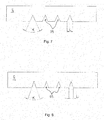
- FIGS. 4 to 8 show possible embodiments of the blade 5 according to the invention.
- the V-shaped of the notch 55 can be observed.
- the latter is defined by two cutting stretches 55A,55B, which are inclined by an angle ⁇ which substantially represents the opening angle of the notch.
- the two stretches 55A,55B intersect defining an "innermost" vertex (indicated by X in Figure 4 ) and are symmetric with respect to a reference axis 201. The latter is aligned with the central axis of the battery 2 during the step of cutting.
- Each of the two stretches 55A,55B of the blade 55 ends at an "outermost" vertex (indicated by Y in Figure 4 ) which represents an intersection point with a rectilinear portion of the cutting edge 51 which develops along a reference direction orthogonal to the axis 201.
- the shape of the notch 55 is identified by the values of the opening angle ⁇ and by its width L, meaning the distance between the two outermost vertexes Y defined above.
- the opening angle ⁇ is chosen from a range of values comprised between 30° and 80°, while the value of the width L is comprised in a range between 10 and 45 mm.
- the thickness S 1 of the blade 5 (indicated in figure 5 ) is comprised in a range between 1 and 4 mm.
- the blade is preferably made of harmonic steel.
- the shape of the notch 55 is chosen as a function of the size, i.e. of the dimensions, of the cylindrical-ype batteries to be cut.
- a classification of the cylindrical batteries is universally used according to their sizes.
- Mini batteries are indicated by the letters AAA, and penlight batteries are indicated by the letters AA.
- R14 batteries are indicated by the letter C and flashlight batteries are indicated by letter D.
- Figure 4 shows an embodiment of the blade 5 which has been found to perform particularly well in the cutting of D-type battery blades.
- Figures 6 and 7 show blades which are found to perform particularly well in the cutting of C-type and AA-type batteries, respectively.
- Figure 8 shows a blade 5 which is particularly adapted to cutting AAA-type batteries.
- the table shows the value of the opening angle ⁇ and of the width L of the notch 55. It is worth noting that for each size indicated in the table, the corresponding values of the opening angle ⁇ and of the width L are to be considered preferred, and therefore not exclusive.
- the edge 51 of the blade 5 comprises a plurality of notches 55, each of which is V-shaped. Even more preferably, all the notches 55 of said plurality have the same shape in terms of width L and of opening angle ⁇ .
- the notches 55 are arranged at a given distance D, measured as the distance between the innermost vertexes X of two adjacent notches.
- the presence of multiple notches 55 allows a greater operative versatility. Indeed, after a given number of batteries cut consecutively by means of the first V-shaped notch, the same blade 5 may be positioned in the cutting device 50 so that the second V-shaped notch, different from the first one, is used to cut another number of batteries.
- the cutting device 50 comprises locking means for locking the cutting blade 5 in a fixed position.
- the pushing and moving means 40 move the battery 2 between a first position, in which the battery 2 is in the seat 61 of the positioning device 60, and a second position having reached which the battery 2 is cut into two halves 2A,2B.
- the cutting station 1 also comprises guiding means for guiding the movement the battery 2 along a direction of advancement which is parallel to the cutting plane 200 defined above and thus parallel to the central axis 100 of the battery 2.
- the cutting device 50 comprises a pair of supporting elements 53A,53B of the blade 5 installed on a base 4 of the cutting station 1.
- the supporting elements 53A,53B are distanced and positioned symmetrically with respect to a reference plane 300 which is substantially vertical and parallel to the direction of advancement 400 along which the battery 2 is moved by the pushing and moving means 40.
- the locking means of the blade 5 comprise a corresponding locking element 52A,52B. The latter is fixed in removable manner to the corresponding supporting element 53A, 53B and in position distanced from the other locking element. The blade 5 thus remains locked between the supporting elements 53A,53B and the corresponding locking elements 52A,52B.
- the blade 5 is arranged so that the V-shaped notch 55 is arranged in the space comprised between the supporting elements 53A,53B and between the corresponding locking elements 52A,52B.
- the amplitude of such a space i.e. the width measured orthogonally to the reference plane 300, is such as to allow the passage of the battery 2 during the step of cutting it.
- the pushing and moving means 40 preferably comprise a hydrodynamic actuator 41 installed on the base 4 in a position substantially opposite to the cutting device 50, in position evaluated with respect to that of the positioning device 60.
- the hydrodynamic actuator 41 comprises a rod 42, the end 42A of which is configured to act on the battery 2.
- the end 42A can act directly on the transversal surface of the battery 2 opposite to that which the blade 5 faces.
- the end 42A could act indirectly on such a transversal surface, e.g. providing a pusher element connected to the end 42A itself and acting directly on the transversal surface.
- the rod 42 can be actuated between the minimum extension position, in which the end 42A does not interact with the battery 2, and a maximum extension position, having reached which the battery 2 is cut due to the blade 5.
- the minimum extension condition of the rod 42 is such that the end 42A does not interact with the battery 2.
- the latter condition substantially corresponds to a condition of deactivation of the hydrodynamic actuator 41 and thus to a condition in which the battery 2 to be cut can be loaded into the seat 61 of the positioning device 60.
- the travel of the rod 42 between the two conditions defined above identifies the direction of advancement 400 of the battery 2 defined above.
- the rod 42 moves starting from the minimum extension condition.
- the end of the rod 42 starts pushing the battery 2 towards the blade 5 along the direction of advancement 400. Such a push continues until the cutting of the battery 2 is completed due to the cutting blade 5.
- the cutting station 1 preferably comprises guiding means of the rod 42.
- such means are defined by a wall 46 fixed to the base 4 and interposed between the positioning device 60 and the actuator 41.
- a wall 46 comprises a through hole crossed by the rod 42 during its travel between the two conditions defined above.
- the guiding station comprises guiding means of the battery 2 to guide it along the direction of advancement 400, between the first position and the second position.
- Such means have the purpose of maintaining the central axis 100 of the battery 2 in position coplanar with the cutting plane 200 during the step of cutting the battery itself.
- such guiding means comprise a chamber 70 defined by a lower half-shell 71 installed on the base 4 and by an upper half-shell 72 fixed to the lower half-shell 71 by means of removable fixing means. Following their union, the two half-shells 71, 72 configure a cylindrical passage, the axis of which is aligned with that of the battery 2 thus remaining coplanar with the cutting plane 200 identified by the blade 5.
- the two half-shells 71,72 maintain such a coplanar condition during the step of cutting so as to ensure the cutting along the diametrical plane.
- the cutting station 1 is preferably provided also with a loading device 80 for automatically loading/positioning the battery 2 in the seat 61 of the positioning device 60.
- a loading device 80 which loads according to a substantially "revolver" principle.
- the loading device 80 comprises a belt element 81 installed between two pulleys 82A,82B supported by a supporting frame (not shown in the figures).
- a first one 82A of these pulleys is a drive pulley because it is actuated by a motor, preferably electric.
- the other pulley 82B is only used for transmission of the belt 81.
- a plurality of battery-holder elements 85 are arranged each of which defines a seat 86 in which a battery 2 can be positioned so that its axis remains parallel to that of rotation of the pulleys 82A,82B.
- a battery 2 intended to be cut by the blade 5 is loaded into each seat 86.
- the battery 2 may be loaded manually or alternatively automatically, exploiting for example a conveyor belt (not shown) as conveying and loading element.
- the loading device 80 is positioned so that the axis of the pulleys is parallel to the direction of advancement 200 and so that one of the pulleys is arranged near the loading device 60 of the cutting station 1. Following the rotation of the belt 81, the battery 2 housed in a seat 86 of one battery-holder element 85 reaches an unloading end of the loading device 80. At each unloading end, the rotation of the battery-holder element 85, determined by the curvature of the belt 81, determines the release of the battery 2 from the seat 86.
- the belt 81 is arranged so that the battery 2, exiting from the seat 86 of the belt 81, is positioned autonomously inside the seat 61 configured by the positioning device 60.
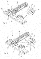
- Figures from 9 to 12 show the operating principle of the cutting station 1 shown in the figures.
- Figure 9 shows the station during the step of automatically loading the battery 2.
- the battery 2 is still housed in the seat 86 of a corresponding battery-holder element 85 of the battery 81.
- the battery 2 is positioned in the seat 61 of the positioning device 60 and its central axis 100 is coplanar with the cutting plane 200. Substantially, the battery 2 is ready to be pushed, by the action of the hydraulic actuator 41, against the blade 5.
- Figure 11 refers to the step of cutting, i.e. in which the battery 2 is pushed against the blade 5 by means of the rod 42 of the hydraulic actuator 41.
- the battery 2 remains, due to the guiding chamber 70, a position such that the central axis 100 remains coplanar with the cutting plane 200 of the blade 2.
- the battery 2 is split into two halves 2A, 2B, as apparent from the enlargement shown in Figure 12 .
- the rod 42 has reached it maximum extension condition which substantially coincides with the completion of the step of cutting.
- the present invention also refers to the method for the dry separation of the components of AA-type batteries 1.
- the purpose of such a method is to separate the black paste, inside the batteries, from the metal part, forming the casing of the batteries themselves, and from any plastic materials which form linings or seals of the batteries.
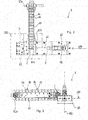
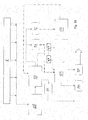
- Figure 14 diagrammatically shows a plant according to the invention which allows the implementation of such a method.
- the method according to the invention comprises a first step which envisage of cutting each battery 2 in two halves 2A,2B along a diametrical plane containing the central axis 100 of the battery itself, in particular the cutting of the battery 2 is preferably performed by means of a blade 5, which identifies a cutting plane 200 and which is provided with a V-shaped notch.
- each battery 2 is cut by generating a relative motion between the battery 2 and the blade 5, so that the central axis 100 of the battery 2 remains coplanar with the cutting plane 200 and so that the battery 2 impacts against the blade 5 at the V-shaped notch 55.
- the step of cutting is preceded by a first preliminary step of dimensionally separating the batteries and by a second preliminary step of separating (following said first step) in which the batteries are separated as a function of their chemical structure.
- the separating method of the components according to the invention comprises a second step, following the first, which includes mechanically striking the two halves 2A,2B of each battery 2 so as to promote the detachment of the black paste from the metal part forming the metal casing defining the battery itself.
- the disaggregation unit 110 comprises a casing defined by a base 111 from which a side containing wall 112 develops so as to generate a volume closed on top, i.e. in position opposite to the base 111, by a lid 113.
- the latter defines an opening 114 through which the halves 2A,2B of the previously cut battery 2 are loaded.
- halves 2A,2B deriving from batteries of different size e.g.
- the disaggregation unit 110 comprises a central pin 116 which emerges internally.
- One or more disaggregation chains 117 made of metal material are connected to such a central pin 116.
- the disaggregation unit 110 is further provided with a motor assembly 118 connected to the central pin 116 to rotate it together with the chain or chains 117. Due to their rotation, in a few seconds the chains 117 strike the cut batteries determining the detachment of the black paste in a substantially granular form.
- the disaggregation unit 110 also comprises an unloading section 115 of the material struck and disaggregated by means of the chains 117. Even more preferably, the disaggregation unit 110 is provided with closing means 119 of said unloading section. Such closing means 119 are activated during the rotation of the chains 117 and then deactivated at the end of said rotation to promote the evacuation of the fragments which are generated.
- the fragments generated in this second step may be structurally homogeneous, i.e. consisting of a single component ( black paste, metal or plastic) or heterogeneous, i.e. consisting of multiple components (e.g. black paste combined with metal and/or with plastic). In all cases, such fragments have different sizes.
- the method according to the invention includes a third step which consists in separating, by means of vibration-sieving, the fragments according to their size.
- the fragments are separated at least into a first fraction F1 and at least into a second fraction F2, wherein such fragments have a maximum size which is respectively higher and lower than a predetermined value.
- a predetermined value is approximately 1 mm.
- the separation into two fractions is preferably performed in a vibration-sieving station 120 comprising at least first sieving means comprising a first vibrating sieve defining openings of amplitude corresponding to said predetermined value.
- the first fraction F1 will consist of fragments which cross the first sieve, while the second fraction F2 will consist of fragments which remain over said sieve.
- the first fraction F1 will consist mainly of black paste granules. In such a first fraction F1 there may also be small fragments of metal and plastic.
- the method according to the invention includes at least a fourth step consisting in the step of magnetically separating the first fraction F1, i.e. separating, by magnetic attraction, the metal part PM from the black paste BP.
- the latter may thus be collected and then subjected to a chemical treatment in order to retrieve its constituent components.
- the metal part PM can be collected and reused or in all cases disposed of independently from the black paste BP.
- the step of magnetically separating may be performed in a magnetic separation unit 125 (or magnetic separator 125) comprising magnetic means adapted to attract the fragments of the metal part related to the casing and/or to the electrodes of the batteries.
- the black paste separated by means of the magnetic separation 125 there may be small fragments of plastic which can be disposed of in the field of the chemical treatment indicated above.
- the large size plastic fragments tend to collect over the vibrating sieve in a different position from the metal fragments and/or the heterogeneous fragments having size higher than the predetermined value in all cases. So, the larger size plastic fragments may be advantageously collected and separated from the second fraction F2.
- the plastic part (indicated by PP) may be thus recovered and recycled in one of the many known processes adapted for the purpose.
- the second fraction F2 of fragments may also undergo a step of magnetic separation or alternatively be disposed of, e.g. in a foundry or more generally in the field of a fusion process in which the presence of elements such as zinc-carbon-manganese is acceptable.
- the second fraction F2 may undergo further steps of dry treatment.
- a step of crushing the second fraction F2 is included having the purpose of detaching the metal fragments from the hardened black paste on them.
- a crushing is made in a crushing unit 130 (or crushing mill 130) as indicated in the system diagrammatically shown in Figure 15 .
- the crushing determines, at least in part, an advantageous reduction in size of the fragments.
- the product deriving from the crushing is subjected to a further step of vibration-sieving.
- This crushing product is broken down into a further first fraction F1* and into a further second fraction F2*, the fragments of which have a diameter lower and higher than the first predetermined value, respectively.
- Said further fraction F1* is then subjected to the step of magnetic separation according to that shown above for the first fraction F1 defined to comment Figure 14 .
- the second fraction F2* obtained by means of the second passage in the vibration sieve 120, will mainly consist of metal fragments which may be possibly separated by means of the further step of magnetic separation.
- the metal fragments may then be reused, e.g. in the field of a metal casting process.
- the second fraction F2* may be reused directly, e.g. in a foundry for the production of manganese steel, without the further step of magnetic separation indicated above.
- a plastic part PP separated from the second fraction F2* indicated above, may collect over the sieve of the vibration-sieving 120 and can thus be recovered and recycled.
- the step of vibration-sieving is performed so as to separate the fragments into a first fraction F1, into a second fraction F2 and into a third fraction F3.
- the maximum size of the fragments is lower than a first predetermined value
- in the second fraction F2 is higher than said first predetermined value and lower than a second predetermined value
- the third fraction F3 the maximum size of the fragments is higher than the second predetermined value.
- the first predetermined value is about 1 mm and wherein said second predetermined value is about 5 mm.
- the vibration-sieving station 120 comprises at least a first vibrating sieve, which defines openings of size corresponding respectively to the first predetermined value, and at least a second vibrating sieve, which defines opening of size corresponding to the second predetermined value.
- the third fraction F3 of fragments (having maximum size higher than said second predetermined value) is defined by the fragments of the second vibrating sieve which were not sieved.
- the first fraction F1 and the second fraction F2 are processed according to the same methods described above with reference to Figure 15 , to which reference is made. Substantially, the first fraction F1 is subjected to magnetic separation, while the second fraction F2 is crushed and then the respective crushing products are subjected to a successive vibration-sieving. The latter step determines the separation into two fractions F1*-F2*, not indicated in Figure 16 only for the sake of clarity.
- the third fraction F3 will mainly consist of metal fragments, the maximum size of which is higher than the second predetermined value.
- a third fraction F3 may also comprise heterogeneous elements made of plastic and hardened black paste, i.e. in the form of clumps.
- the third fraction F3 is magnetically separated in order to separate the fragments of the mixed part PM consisting of homogeneous fragments of plastic or hardened black paste or of heterogeneous fragments consisting of black paste and plastic.
- Such a mixed part PM is then subjected to the same steps of treating provided for the second fraction F2. More precisely, the mixed part PM undergoes a step of crushing in the crushing station 130 the main purpose of which is to crush the black paste clumps.
- the products of such a crushing are sent directly to the vibration-sieving station 120.
- the crushed products could be sent firstly to the disaggregation station 110 and only later to the vibrating sieving station 120.
- the preventive passage in the disaggregation station 110 further promotes the separation of the fragments of black paste from those of plastic material.
- the passage of the crushed products in the vibration-sieving station allows to collect a further plastic part PP consisting of plastic fragments of maximum size higher than the second predetermined value.
- a passage determines at least one further first fraction F1-3 and at least a second fraction F2-3 of fragments having a maximum size lower and higher than the first predetermined value.
- the first fraction F1-3 and/or the second fraction F2-3 deriving from the second passage in the vibration-sieving station 120 may be subjected to a further step of magnetic separation to separate the metal part PM from the black paste BP.
- the second fraction F2-3 could be directly recycled.
- the present invention further relates to a system for implementing the method shown above.
- a system further comprises at least one cutting station 1, preferably having the peculiarities described above, a disaggregation station 110, operatively downstream of the cutting station 1, a vibrating sieving station 120 and at least one magnetic separation station 125.
- the system further comprises a grinding station 130 with the purposes described above.
Landscapes
- Engineering & Computer Science (AREA)
- Life Sciences & Earth Sciences (AREA)
- Forests & Forestry (AREA)
- Mechanical Engineering (AREA)
- Manufacturing & Machinery (AREA)
- Chemical & Material Sciences (AREA)
- Chemical Kinetics & Catalysis (AREA)
- Electrochemistry (AREA)
- General Chemical & Material Sciences (AREA)
- Sustainable Development (AREA)
- Secondary Cells (AREA)
- Processing Of Solid Wastes (AREA)
Priority Applications (5)
| Application Number | Priority Date | Filing Date | Title |
|---|---|---|---|
| EP17189197.1A EP3450122B1 (en) | 2017-09-04 | 2017-09-04 | Station for cutting aa-type, d-type and/or c-type batteries, method for separating and recovering components of said batteries and system for implementing such a method |
| PL17189197T PL3450122T3 (pl) | 2017-09-04 | 2017-09-04 | Stanowisko do cięcia baterii typu AA, typu D i/lub typu C, sposób rozdzielania i odzyskiwania składników wspomnianych baterii i układ do realizacji takiego sposobu |
| PCT/EP2018/073689 WO2019043242A1 (en) | 2017-09-04 | 2018-09-04 | AA, TYPE D AND / OR TYPE C BATTERY STATION, METHOD FOR SEPARATING AND RECOVERING COMPONENTS THEREOF, AND SYSTEM FOR IMPLEMENTING SUCH A METHOD |
| CA3074624A CA3074624A1 (en) | 2017-09-04 | 2018-09-04 | Station for cutting aa-type, d-type and/or c-type batteries, method for separating and recovering components of said batteries and system for implementing such a method |
| US16/644,043 US20210162617A1 (en) | 2017-09-04 | 2018-09-04 | Station for cutting aa-type, d-type and/or c-type batteries, method for separating and recovering components of said batteries and system for implementing such method |
Applications Claiming Priority (1)
| Application Number | Priority Date | Filing Date | Title |
|---|---|---|---|
| EP17189197.1A EP3450122B1 (en) | 2017-09-04 | 2017-09-04 | Station for cutting aa-type, d-type and/or c-type batteries, method for separating and recovering components of said batteries and system for implementing such a method |
Publications (2)
| Publication Number | Publication Date |
|---|---|
| EP3450122A1 EP3450122A1 (en) | 2019-03-06 |
| EP3450122B1 true EP3450122B1 (en) | 2021-12-01 |
Family
ID=60190532
Family Applications (1)
| Application Number | Title | Priority Date | Filing Date |
|---|---|---|---|
| EP17189197.1A Not-in-force EP3450122B1 (en) | 2017-09-04 | 2017-09-04 | Station for cutting aa-type, d-type and/or c-type batteries, method for separating and recovering components of said batteries and system for implementing such a method |
Country Status (5)
| Country | Link |
|---|---|
| US (1) | US20210162617A1 (pl) |
| EP (1) | EP3450122B1 (pl) |
| CA (1) | CA3074624A1 (pl) |
| PL (1) | PL3450122T3 (pl) |
| WO (1) | WO2019043242A1 (pl) |
Families Citing this family (4)
| Publication number | Priority date | Publication date | Assignee | Title |
|---|---|---|---|---|
| EP3450578B1 (en) * | 2017-09-04 | 2021-05-12 | Evh S.R.L. In Liquidazione | Chemical process for the recovery of alkaline and zinc-carbon battery components |
| CN111416171B (zh) * | 2020-04-26 | 2024-07-30 | 河北中化锂电科技有限公司 | 动力电池分离装置 |
| US20240399603A1 (en) * | 2023-06-01 | 2024-12-05 | GM Global Technology Operations LLC | Method and system for energy cell disassembly |
| CN118455649A (zh) * | 2024-07-12 | 2024-08-09 | 宁德时代新能源科技股份有限公司 | 一种切割装置及切割方法、电池加工设备 |
Family Cites Families (14)
| Publication number | Priority date | Publication date | Assignee | Title |
|---|---|---|---|---|
| US1374278A (en) * | 1919-08-25 | 1921-04-12 | Burch Julius Gordon | Device for cutting wire cable |
| US1798106A (en) * | 1928-10-13 | 1931-03-24 | Pels Henry | Shears for cutting profiled material |
| FR1082614A (fr) * | 1951-12-14 | 1954-12-30 | Procédé de récupération de produits emballés, notamment applicable à la récupération du zinc des piles électriques et appareillage permettant sa mise en oeuvre | |
| US3152504A (en) * | 1961-12-06 | 1964-10-13 | Robert T Brown | Apparatus for recovering lead from storage batteries |
| US3269870A (en) * | 1964-04-15 | 1966-08-30 | Abramson Jack | Method of removing lead plates from batteries |
| US3771401A (en) * | 1972-01-10 | 1973-11-13 | D Jasinski | Sheetmetal shearing apparatus |
| JPS588472Y2 (ja) * | 1980-04-26 | 1983-02-15 | 留一 塩田 | 午「ぼう」等の分割切断カツタ− |
| JPS61277168A (ja) * | 1985-05-31 | 1986-12-08 | Yasuo Nakatsuji | 使用済乾電池の解体処理装置並びにこれを用いて行なう使用済乾電池の解体処理方法 |
| DE19610093A1 (de) | 1996-03-15 | 1997-09-18 | Bsbg Bremer Sonderabfall Berat | Verfahren zum Sortieren von Altbatterien und/oder Altakkumulatoren sowie Vorrichtung zur Durchführung des Verfahrens |
| AU5619699A (en) | 1998-08-06 | 2000-02-28 | Tredi | Automatic sorting of battery power packs |
| DE10010556A1 (de) | 2000-03-08 | 2001-09-13 | Bremer Sonderabfall Beratungsg | Detektor zum Messen der Dosisleistung sowie Vorrichtung zum Sortieren von Altbatterien oder Altakkumulatoren nach ihrem Typ |
| US8505870B2 (en) * | 2011-02-02 | 2013-08-13 | Hydril Usa Manufacturing Llc | Shear blade geometry and method |
| KR101231893B1 (ko) * | 2011-03-22 | 2013-02-08 | 주식회사 익스톨 | 폐리튬 전지 재활용 장치 |
| US20140182441A1 (en) * | 2012-03-23 | 2014-07-03 | Philip J Pisczak | Cutter dies |
-
2017
- 2017-09-04 PL PL17189197T patent/PL3450122T3/pl unknown
- 2017-09-04 EP EP17189197.1A patent/EP3450122B1/en not_active Not-in-force
-
2018
- 2018-09-04 CA CA3074624A patent/CA3074624A1/en active Pending
- 2018-09-04 WO PCT/EP2018/073689 patent/WO2019043242A1/en not_active Ceased
- 2018-09-04 US US16/644,043 patent/US20210162617A1/en not_active Abandoned
Non-Patent Citations (1)
| Title |
|---|
| None * |
Also Published As
| Publication number | Publication date |
|---|---|
| WO2019043242A1 (en) | 2019-03-07 |
| PL3450122T3 (pl) | 2022-05-30 |
| EP3450122A1 (en) | 2019-03-06 |
| US20210162617A1 (en) | 2021-06-03 |
| CA3074624A1 (en) | 2019-03-07 |
Similar Documents
| Publication | Publication Date | Title |
|---|---|---|
| US20210162617A1 (en) | Station for cutting aa-type, d-type and/or c-type batteries, method for separating and recovering components of said batteries and system for implementing such method | |
| KR102407105B1 (ko) | 폐배터리 모듈 절단장치 및 이를 이용한 폐배터리 재활용 전처리 방법 | |
| CN108711651B (zh) | 一种废旧电池的资源化回收利用工艺和系统 | |
| CN111162338B (zh) | 一种废旧锂电池组拆解回收设备 | |
| KR100637680B1 (ko) | 폐리튬 이차전지로부터 코발트 파우더의 회수장치 및회수방법 | |
| US20230055166A1 (en) | Electrode separation by sonication | |
| CN107086334A (zh) | 一种废旧动力锂电池自动化拆分全组分洁净回收方法 | |
| JP2013004299A (ja) | リチウムイオン二次電池のリサイクル方法 | |
| EP2182569B1 (de) | Verfahren und Vorrichtung zum Verwerten eines elektrochemischen Energiespeichers | |
| JP5767806B2 (ja) | 廃電池分別機 | |
| KR20230110485A (ko) | 리튬 이온 배터리 재활용 방법, 장치 및 시스템 | |
| EP4447194A1 (en) | Storage battery recycling device | |
| WO2023086884A1 (en) | Li-ion battery recycling process and system for black mass fractionation and recovery of specific materials | |
| CN108461855A (zh) | 一种废旧锂电池的拆解回收系统及拆解回收方法 | |
| Islam et al. | Review on the recycling of anode graphite from waste lithium-ion batteries | |
| CN110299576B (zh) | 一种电池拆解装置 | |
| CN111801840A (zh) | 回收锂离子蓄电池的方法 | |
| JP6994418B2 (ja) | 廃リチウムイオン電池の処理装置及び処理方法 | |
| US20240165633A1 (en) | Crushing and classifying device and method for crushing and classifying electrode material | |
| US20240058897A1 (en) | Method for processing rechargeable batteries | |
| EP3450578B1 (en) | Chemical process for the recovery of alkaline and zinc-carbon battery components | |
| KR102910593B1 (ko) | 폐전지 처리 장치 | |
| US20250070296A1 (en) | Lithium-ion battery recycling method | |
| WO2022263812A1 (en) | Battery recycling | |
| KR102723419B1 (ko) | 폐배터리 재활용 방법 |
Legal Events
| Date | Code | Title | Description |
|---|---|---|---|
| PUAI | Public reference made under article 153(3) epc to a published international application that has entered the european phase |
Free format text: ORIGINAL CODE: 0009012 |
|
| STAA | Information on the status of an ep patent application or granted ep patent |
Free format text: STATUS: THE APPLICATION HAS BEEN PUBLISHED |
|
| AK | Designated contracting states |
Kind code of ref document: A1 Designated state(s): AL AT BE BG CH CY CZ DE DK EE ES FI FR GB GR HR HU IE IS IT LI LT LU LV MC MK MT NL NO PL PT RO RS SE SI SK SM TR |
|
| AX | Request for extension of the european patent |
Extension state: BA ME |
|
| STAA | Information on the status of an ep patent application or granted ep patent |
Free format text: STATUS: REQUEST FOR EXAMINATION WAS MADE |
|
| 17P | Request for examination filed |
Effective date: 20190905 |
|
| RBV | Designated contracting states (corrected) |
Designated state(s): AL AT BE BG CH CY CZ DE DK EE ES FI FR GB GR HR HU IE IS IT LI LT LU LV MC MK MT NL NO PL PT RO RS SE SI SK SM TR |
|
| RIC1 | Information provided on ipc code assigned before grant |
Ipc: H01M 6/06 20060101ALI20200304BHEP Ipc: B26D 1/02 20060101AFI20200304BHEP Ipc: B26D 3/30 20060101ALI20200304BHEP Ipc: B26D 3/00 20060101ALI20200304BHEP Ipc: B26D 7/06 20060101ALI20200304BHEP Ipc: B26D 1/00 20060101ALN20200304BHEP Ipc: H01M 6/52 20060101ALI20200304BHEP |
|
| GRAP | Despatch of communication of intention to grant a patent |
Free format text: ORIGINAL CODE: EPIDOSNIGR1 |
|
| STAA | Information on the status of an ep patent application or granted ep patent |
Free format text: STATUS: GRANT OF PATENT IS INTENDED |
|
| RIC1 | Information provided on ipc code assigned before grant |
Ipc: H01M 6/06 20060101ALI20200309BHEP Ipc: H01M 6/52 20060101ALI20200309BHEP Ipc: B26D 1/00 20060101ALN20200309BHEP Ipc: B26D 7/06 20060101ALI20200309BHEP Ipc: B26D 3/00 20060101ALI20200309BHEP Ipc: B26D 3/30 20060101ALI20200309BHEP Ipc: B26D 1/02 20060101AFI20200309BHEP |
|
| RIC1 | Information provided on ipc code assigned before grant |
Ipc: H01M 6/52 20060101ALI20200319BHEP Ipc: B26D 7/06 20060101ALI20200319BHEP Ipc: B26D 3/00 20060101ALI20200319BHEP Ipc: B26D 3/30 20060101ALI20200319BHEP Ipc: B26D 1/02 20060101AFI20200319BHEP Ipc: H01M 6/06 20060101ALI20200319BHEP Ipc: B26D 1/00 20060101ALN20200319BHEP |
|
| INTG | Intention to grant announced |
Effective date: 20200415 |
|
| GRAJ | Information related to disapproval of communication of intention to grant by the applicant or resumption of examination proceedings by the epo deleted |
Free format text: ORIGINAL CODE: EPIDOSDIGR1 |
|
| STAA | Information on the status of an ep patent application or granted ep patent |
Free format text: STATUS: REQUEST FOR EXAMINATION WAS MADE |
|
| INTC | Intention to grant announced (deleted) | ||
| GRAS | Grant fee paid |
Free format text: ORIGINAL CODE: EPIDOSNIGR3 |
|
| STAA | Information on the status of an ep patent application or granted ep patent |
Free format text: STATUS: GRANT OF PATENT IS INTENDED |
|
| GRAP | Despatch of communication of intention to grant a patent |
Free format text: ORIGINAL CODE: EPIDOSNIGR1 |
|
| RAP3 | Party data changed (applicant data changed or rights of an application transferred) |
Owner name: EVH S.R.L. IN LIQUIDAZIONE |
|
| RIC1 | Information provided on ipc code assigned before grant |
Ipc: B26D 1/02 20060101AFI20210630BHEP Ipc: B26D 3/00 20060101ALI20210630BHEP Ipc: B26D 7/06 20060101ALI20210630BHEP Ipc: B26D 3/30 20060101ALI20210630BHEP Ipc: H01M 6/06 20060101ALI20210630BHEP Ipc: H01M 6/52 20060101ALI20210630BHEP Ipc: B26D 1/00 20060101ALN20210630BHEP |
|
| INTG | Intention to grant announced |
Effective date: 20210721 |
|
| GRAA | (expected) grant |
Free format text: ORIGINAL CODE: 0009210 |
|
| STAA | Information on the status of an ep patent application or granted ep patent |
Free format text: STATUS: THE PATENT HAS BEEN GRANTED |
|
| AK | Designated contracting states |
Kind code of ref document: B1 Designated state(s): AL AT BE BG CH CY CZ DE DK EE ES FI FR GB GR HR HU IE IS IT LI LT LU LV MC MK MT NL NO PL PT RO RS SE SI SK SM TR |
|
| REG | Reference to a national code |
Ref country code: GB Ref legal event code: FG4D |
|
| REG | Reference to a national code |
Ref country code: AT Ref legal event code: REF Ref document number: 1451318 Country of ref document: AT Kind code of ref document: T Effective date: 20211215 Ref country code: CH Ref legal event code: EP |
|
| REG | Reference to a national code |
Ref country code: IE Ref legal event code: FG4D |
|
| REG | Reference to a national code |
Ref country code: DE Ref legal event code: R096 Ref document number: 602017050071 Country of ref document: DE |
|
| REG | Reference to a national code |
Ref country code: NL Ref legal event code: FP |
|
| REG | Reference to a national code |
Ref country code: LT Ref legal event code: MG9D |
|
| REG | Reference to a national code |
Ref country code: AT Ref legal event code: MK05 Ref document number: 1451318 Country of ref document: AT Kind code of ref document: T Effective date: 20211201 |
|
| PG25 | Lapsed in a contracting state [announced via postgrant information from national office to epo] |
Ref country code: RS Free format text: LAPSE BECAUSE OF FAILURE TO SUBMIT A TRANSLATION OF THE DESCRIPTION OR TO PAY THE FEE WITHIN THE PRESCRIBED TIME-LIMIT Effective date: 20211201 Ref country code: LT Free format text: LAPSE BECAUSE OF FAILURE TO SUBMIT A TRANSLATION OF THE DESCRIPTION OR TO PAY THE FEE WITHIN THE PRESCRIBED TIME-LIMIT Effective date: 20211201 Ref country code: FI Free format text: LAPSE BECAUSE OF FAILURE TO SUBMIT A TRANSLATION OF THE DESCRIPTION OR TO PAY THE FEE WITHIN THE PRESCRIBED TIME-LIMIT Effective date: 20211201 Ref country code: BG Free format text: LAPSE BECAUSE OF FAILURE TO SUBMIT A TRANSLATION OF THE DESCRIPTION OR TO PAY THE FEE WITHIN THE PRESCRIBED TIME-LIMIT Effective date: 20220301 Ref country code: AT Free format text: LAPSE BECAUSE OF FAILURE TO SUBMIT A TRANSLATION OF THE DESCRIPTION OR TO PAY THE FEE WITHIN THE PRESCRIBED TIME-LIMIT Effective date: 20211201 |
|
| PG25 | Lapsed in a contracting state [announced via postgrant information from national office to epo] |
Ref country code: SE Free format text: LAPSE BECAUSE OF FAILURE TO SUBMIT A TRANSLATION OF THE DESCRIPTION OR TO PAY THE FEE WITHIN THE PRESCRIBED TIME-LIMIT Effective date: 20211201 Ref country code: NO Free format text: LAPSE BECAUSE OF FAILURE TO SUBMIT A TRANSLATION OF THE DESCRIPTION OR TO PAY THE FEE WITHIN THE PRESCRIBED TIME-LIMIT Effective date: 20220301 Ref country code: LV Free format text: LAPSE BECAUSE OF FAILURE TO SUBMIT A TRANSLATION OF THE DESCRIPTION OR TO PAY THE FEE WITHIN THE PRESCRIBED TIME-LIMIT Effective date: 20211201 Ref country code: HR Free format text: LAPSE BECAUSE OF FAILURE TO SUBMIT A TRANSLATION OF THE DESCRIPTION OR TO PAY THE FEE WITHIN THE PRESCRIBED TIME-LIMIT Effective date: 20211201 Ref country code: GR Free format text: LAPSE BECAUSE OF FAILURE TO SUBMIT A TRANSLATION OF THE DESCRIPTION OR TO PAY THE FEE WITHIN THE PRESCRIBED TIME-LIMIT Effective date: 20220302 Ref country code: ES Free format text: LAPSE BECAUSE OF FAILURE TO SUBMIT A TRANSLATION OF THE DESCRIPTION OR TO PAY THE FEE WITHIN THE PRESCRIBED TIME-LIMIT Effective date: 20211201 |
|
| PG25 | Lapsed in a contracting state [announced via postgrant information from national office to epo] |
Ref country code: SM Free format text: LAPSE BECAUSE OF FAILURE TO SUBMIT A TRANSLATION OF THE DESCRIPTION OR TO PAY THE FEE WITHIN THE PRESCRIBED TIME-LIMIT Effective date: 20211201 Ref country code: SK Free format text: LAPSE BECAUSE OF FAILURE TO SUBMIT A TRANSLATION OF THE DESCRIPTION OR TO PAY THE FEE WITHIN THE PRESCRIBED TIME-LIMIT Effective date: 20211201 Ref country code: RO Free format text: LAPSE BECAUSE OF FAILURE TO SUBMIT A TRANSLATION OF THE DESCRIPTION OR TO PAY THE FEE WITHIN THE PRESCRIBED TIME-LIMIT Effective date: 20211201 Ref country code: PT Free format text: LAPSE BECAUSE OF FAILURE TO SUBMIT A TRANSLATION OF THE DESCRIPTION OR TO PAY THE FEE WITHIN THE PRESCRIBED TIME-LIMIT Effective date: 20220401 Ref country code: EE Free format text: LAPSE BECAUSE OF FAILURE TO SUBMIT A TRANSLATION OF THE DESCRIPTION OR TO PAY THE FEE WITHIN THE PRESCRIBED TIME-LIMIT Effective date: 20211201 Ref country code: CZ Free format text: LAPSE BECAUSE OF FAILURE TO SUBMIT A TRANSLATION OF THE DESCRIPTION OR TO PAY THE FEE WITHIN THE PRESCRIBED TIME-LIMIT Effective date: 20211201 |
|
| REG | Reference to a national code |
Ref country code: DE Ref legal event code: R097 Ref document number: 602017050071 Country of ref document: DE |
|
| PG25 | Lapsed in a contracting state [announced via postgrant information from national office to epo] |
Ref country code: IS Free format text: LAPSE BECAUSE OF FAILURE TO SUBMIT A TRANSLATION OF THE DESCRIPTION OR TO PAY THE FEE WITHIN THE PRESCRIBED TIME-LIMIT Effective date: 20220401 |
|
| PLBE | No opposition filed within time limit |
Free format text: ORIGINAL CODE: 0009261 |
|
| STAA | Information on the status of an ep patent application or granted ep patent |
Free format text: STATUS: NO OPPOSITION FILED WITHIN TIME LIMIT |
|
| PG25 | Lapsed in a contracting state [announced via postgrant information from national office to epo] |
Ref country code: DK Free format text: LAPSE BECAUSE OF FAILURE TO SUBMIT A TRANSLATION OF THE DESCRIPTION OR TO PAY THE FEE WITHIN THE PRESCRIBED TIME-LIMIT Effective date: 20211201 Ref country code: AL Free format text: LAPSE BECAUSE OF FAILURE TO SUBMIT A TRANSLATION OF THE DESCRIPTION OR TO PAY THE FEE WITHIN THE PRESCRIBED TIME-LIMIT Effective date: 20211201 |
|
| 26N | No opposition filed |
Effective date: 20220902 |
|
| PG25 | Lapsed in a contracting state [announced via postgrant information from national office to epo] |
Ref country code: SI Free format text: LAPSE BECAUSE OF FAILURE TO SUBMIT A TRANSLATION OF THE DESCRIPTION OR TO PAY THE FEE WITHIN THE PRESCRIBED TIME-LIMIT Effective date: 20211201 |
|
| PG25 | Lapsed in a contracting state [announced via postgrant information from national office to epo] |
Ref country code: MC Free format text: LAPSE BECAUSE OF FAILURE TO SUBMIT A TRANSLATION OF THE DESCRIPTION OR TO PAY THE FEE WITHIN THE PRESCRIBED TIME-LIMIT Effective date: 20211201 |
|
| REG | Reference to a national code |
Ref country code: CH Ref legal event code: PL |
|
| PG25 | Lapsed in a contracting state [announced via postgrant information from national office to epo] |
Ref country code: LU Free format text: LAPSE BECAUSE OF NON-PAYMENT OF DUE FEES Effective date: 20220904 |
|
| PG25 | Lapsed in a contracting state [announced via postgrant information from national office to epo] |
Ref country code: LI Free format text: LAPSE BECAUSE OF NON-PAYMENT OF DUE FEES Effective date: 20220930 Ref country code: IE Free format text: LAPSE BECAUSE OF NON-PAYMENT OF DUE FEES Effective date: 20220904 Ref country code: CH Free format text: LAPSE BECAUSE OF NON-PAYMENT OF DUE FEES Effective date: 20220930 |
|
| PGFP | Annual fee paid to national office [announced via postgrant information from national office to epo] |
Ref country code: NL Payment date: 20231016 Year of fee payment: 7 |
|
| PGFP | Annual fee paid to national office [announced via postgrant information from national office to epo] |
Ref country code: GB Payment date: 20231006 Year of fee payment: 7 |
|
| PGFP | Annual fee paid to national office [announced via postgrant information from national office to epo] |
Ref country code: IT Payment date: 20231025 Year of fee payment: 7 Ref country code: FR Payment date: 20231016 Year of fee payment: 7 Ref country code: DE Payment date: 20231010 Year of fee payment: 7 |
|
| PGFP | Annual fee paid to national office [announced via postgrant information from national office to epo] |
Ref country code: PL Payment date: 20231016 Year of fee payment: 7 Ref country code: BE Payment date: 20231016 Year of fee payment: 7 |
|
| PG25 | Lapsed in a contracting state [announced via postgrant information from national office to epo] |
Ref country code: HU Free format text: LAPSE BECAUSE OF FAILURE TO SUBMIT A TRANSLATION OF THE DESCRIPTION OR TO PAY THE FEE WITHIN THE PRESCRIBED TIME-LIMIT; INVALID AB INITIO Effective date: 20170904 |
|
| PG25 | Lapsed in a contracting state [announced via postgrant information from national office to epo] |
Ref country code: CY Free format text: LAPSE BECAUSE OF FAILURE TO SUBMIT A TRANSLATION OF THE DESCRIPTION OR TO PAY THE FEE WITHIN THE PRESCRIBED TIME-LIMIT Effective date: 20211201 |
|
| PG25 | Lapsed in a contracting state [announced via postgrant information from national office to epo] |
Ref country code: MK Free format text: LAPSE BECAUSE OF FAILURE TO SUBMIT A TRANSLATION OF THE DESCRIPTION OR TO PAY THE FEE WITHIN THE PRESCRIBED TIME-LIMIT Effective date: 20211201 |
|
| PG25 | Lapsed in a contracting state [announced via postgrant information from national office to epo] |
Ref country code: MT Free format text: LAPSE BECAUSE OF FAILURE TO SUBMIT A TRANSLATION OF THE DESCRIPTION OR TO PAY THE FEE WITHIN THE PRESCRIBED TIME-LIMIT Effective date: 20211201 |
|
| REG | Reference to a national code |
Ref country code: DE Ref legal event code: R119 Ref document number: 602017050071 Country of ref document: DE |
|
| REG | Reference to a national code |
Ref country code: NL Ref legal event code: MM Effective date: 20241001 |
|
| GBPC | Gb: european patent ceased through non-payment of renewal fee |
Effective date: 20240904 |
|
| PG25 | Lapsed in a contracting state [announced via postgrant information from national office to epo] |
Ref country code: NL Free format text: LAPSE BECAUSE OF NON-PAYMENT OF DUE FEES Effective date: 20241001 |
|
| PG25 | Lapsed in a contracting state [announced via postgrant information from national office to epo] |
Ref country code: DE Free format text: LAPSE BECAUSE OF NON-PAYMENT OF DUE FEES Effective date: 20250401 |
|
| PG25 | Lapsed in a contracting state [announced via postgrant information from national office to epo] |
Ref country code: GB Free format text: LAPSE BECAUSE OF NON-PAYMENT OF DUE FEES Effective date: 20240904 |
|
| REG | Reference to a national code |
Ref country code: BE Ref legal event code: MM Effective date: 20240930 |
|
| PG25 | Lapsed in a contracting state [announced via postgrant information from national office to epo] |
Ref country code: IT Free format text: LAPSE BECAUSE OF NON-PAYMENT OF DUE FEES Effective date: 20240904 Ref country code: BE Free format text: LAPSE BECAUSE OF NON-PAYMENT OF DUE FEES Effective date: 20240930 |
|
| PG25 | Lapsed in a contracting state [announced via postgrant information from national office to epo] |
Ref country code: FR Free format text: LAPSE BECAUSE OF NON-PAYMENT OF DUE FEES Effective date: 20240930 |
|
| PG25 | Lapsed in a contracting state [announced via postgrant information from national office to epo] |
Ref country code: TR Free format text: LAPSE BECAUSE OF FAILURE TO SUBMIT A TRANSLATION OF THE DESCRIPTION OR TO PAY THE FEE WITHIN THE PRESCRIBED TIME-LIMIT Effective date: 20211201 |
|
| PG25 | Lapsed in a contracting state [announced via postgrant information from national office to epo] |
Ref country code: PL Free format text: LAPSE BECAUSE OF NON-PAYMENT OF DUE FEES Effective date: 20240904 |