EP3450080A1 - Spot welding device, spot welding method, and joint structure - Google Patents
Spot welding device, spot welding method, and joint structure Download PDFInfo
- Publication number
- EP3450080A1 EP3450080A1 EP17789680.0A EP17789680A EP3450080A1 EP 3450080 A1 EP3450080 A1 EP 3450080A1 EP 17789680 A EP17789680 A EP 17789680A EP 3450080 A1 EP3450080 A1 EP 3450080A1
- Authority
- EP
- European Patent Office
- Prior art keywords
- welding
- friction stir
- spot
- plate materials
- resistance spot
- Prior art date
- Legal status (The legal status is an assumption and is not a legal conclusion. Google has not performed a legal analysis and makes no representation as to the accuracy of the status listed.)
- Granted
Links
Images


Classifications
-
- B—PERFORMING OPERATIONS; TRANSPORTING
- B23—MACHINE TOOLS; METAL-WORKING NOT OTHERWISE PROVIDED FOR
- B23K—SOLDERING OR UNSOLDERING; WELDING; CLADDING OR PLATING BY SOLDERING OR WELDING; CUTTING BY APPLYING HEAT LOCALLY, e.g. FLAME CUTTING; WORKING BY LASER BEAM
- B23K11/00—Resistance welding; Severing by resistance heating
- B23K11/10—Spot welding; Stitch welding
- B23K11/11—Spot welding
-
- B—PERFORMING OPERATIONS; TRANSPORTING
- B23—MACHINE TOOLS; METAL-WORKING NOT OTHERWISE PROVIDED FOR
- B23K—SOLDERING OR UNSOLDERING; WELDING; CLADDING OR PLATING BY SOLDERING OR WELDING; CUTTING BY APPLYING HEAT LOCALLY, e.g. FLAME CUTTING; WORKING BY LASER BEAM
- B23K11/00—Resistance welding; Severing by resistance heating
- B23K11/10—Spot welding; Stitch welding
- B23K11/11—Spot welding
- B23K11/115—Spot welding by means of two electrodes placed opposite one another on both sides of the welded parts
-
- B—PERFORMING OPERATIONS; TRANSPORTING
- B23—MACHINE TOOLS; METAL-WORKING NOT OTHERWISE PROVIDED FOR
- B23K—SOLDERING OR UNSOLDERING; WELDING; CLADDING OR PLATING BY SOLDERING OR WELDING; CUTTING BY APPLYING HEAT LOCALLY, e.g. FLAME CUTTING; WORKING BY LASER BEAM
- B23K11/00—Resistance welding; Severing by resistance heating
- B23K11/16—Resistance welding; Severing by resistance heating taking account of the properties of the material to be welded
-
- B—PERFORMING OPERATIONS; TRANSPORTING
- B23—MACHINE TOOLS; METAL-WORKING NOT OTHERWISE PROVIDED FOR
- B23K—SOLDERING OR UNSOLDERING; WELDING; CLADDING OR PLATING BY SOLDERING OR WELDING; CUTTING BY APPLYING HEAT LOCALLY, e.g. FLAME CUTTING; WORKING BY LASER BEAM
- B23K20/00—Non-electric welding by applying impact or other pressure, with or without the application of heat, e.g. cladding or plating
- B23K20/12—Non-electric welding by applying impact or other pressure, with or without the application of heat, e.g. cladding or plating the heat being generated by friction; Friction welding
-
- B—PERFORMING OPERATIONS; TRANSPORTING
- B23—MACHINE TOOLS; METAL-WORKING NOT OTHERWISE PROVIDED FOR
- B23K—SOLDERING OR UNSOLDERING; WELDING; CLADDING OR PLATING BY SOLDERING OR WELDING; CUTTING BY APPLYING HEAT LOCALLY, e.g. FLAME CUTTING; WORKING BY LASER BEAM
- B23K20/00—Non-electric welding by applying impact or other pressure, with or without the application of heat, e.g. cladding or plating
- B23K20/12—Non-electric welding by applying impact or other pressure, with or without the application of heat, e.g. cladding or plating the heat being generated by friction; Friction welding
- B23K20/122—Non-electric welding by applying impact or other pressure, with or without the application of heat, e.g. cladding or plating the heat being generated by friction; Friction welding using a non-consumable tool, e.g. friction stir welding
- B23K20/123—Controlling or monitoring the welding process
-
- B—PERFORMING OPERATIONS; TRANSPORTING
- B23—MACHINE TOOLS; METAL-WORKING NOT OTHERWISE PROVIDED FOR
- B23K—SOLDERING OR UNSOLDERING; WELDING; CLADDING OR PLATING BY SOLDERING OR WELDING; CUTTING BY APPLYING HEAT LOCALLY, e.g. FLAME CUTTING; WORKING BY LASER BEAM
- B23K20/00—Non-electric welding by applying impact or other pressure, with or without the application of heat, e.g. cladding or plating
- B23K20/12—Non-electric welding by applying impact or other pressure, with or without the application of heat, e.g. cladding or plating the heat being generated by friction; Friction welding
- B23K20/122—Non-electric welding by applying impact or other pressure, with or without the application of heat, e.g. cladding or plating the heat being generated by friction; Friction welding using a non-consumable tool, e.g. friction stir welding
- B23K20/1245—Non-electric welding by applying impact or other pressure, with or without the application of heat, e.g. cladding or plating the heat being generated by friction; Friction welding using a non-consumable tool, e.g. friction stir welding characterised by the apparatus
-
- B—PERFORMING OPERATIONS; TRANSPORTING
- B23—MACHINE TOOLS; METAL-WORKING NOT OTHERWISE PROVIDED FOR
- B23K—SOLDERING OR UNSOLDERING; WELDING; CLADDING OR PLATING BY SOLDERING OR WELDING; CUTTING BY APPLYING HEAT LOCALLY, e.g. FLAME CUTTING; WORKING BY LASER BEAM
- B23K20/00—Non-electric welding by applying impact or other pressure, with or without the application of heat, e.g. cladding or plating
- B23K20/12—Non-electric welding by applying impact or other pressure, with or without the application of heat, e.g. cladding or plating the heat being generated by friction; Friction welding
- B23K20/122—Non-electric welding by applying impact or other pressure, with or without the application of heat, e.g. cladding or plating the heat being generated by friction; Friction welding using a non-consumable tool, e.g. friction stir welding
- B23K20/1245—Non-electric welding by applying impact or other pressure, with or without the application of heat, e.g. cladding or plating the heat being generated by friction; Friction welding using a non-consumable tool, e.g. friction stir welding characterised by the apparatus
- B23K20/125—Rotary tool drive mechanism
-
- B—PERFORMING OPERATIONS; TRANSPORTING
- B23—MACHINE TOOLS; METAL-WORKING NOT OTHERWISE PROVIDED FOR
- B23K—SOLDERING OR UNSOLDERING; WELDING; CLADDING OR PLATING BY SOLDERING OR WELDING; CUTTING BY APPLYING HEAT LOCALLY, e.g. FLAME CUTTING; WORKING BY LASER BEAM
- B23K20/00—Non-electric welding by applying impact or other pressure, with or without the application of heat, e.g. cladding or plating
- B23K20/12—Non-electric welding by applying impact or other pressure, with or without the application of heat, e.g. cladding or plating the heat being generated by friction; Friction welding
- B23K20/122—Non-electric welding by applying impact or other pressure, with or without the application of heat, e.g. cladding or plating the heat being generated by friction; Friction welding using a non-consumable tool, e.g. friction stir welding
- B23K20/1265—Non-butt welded joints, e.g. overlap-joints, T-joints or spot welds
-
- B—PERFORMING OPERATIONS; TRANSPORTING
- B23—MACHINE TOOLS; METAL-WORKING NOT OTHERWISE PROVIDED FOR
- B23K—SOLDERING OR UNSOLDERING; WELDING; CLADDING OR PLATING BY SOLDERING OR WELDING; CUTTING BY APPLYING HEAT LOCALLY, e.g. FLAME CUTTING; WORKING BY LASER BEAM
- B23K28/00—Welding or cutting not covered by groups B23K5/00 - B23K26/00
- B23K28/02—Combined welding or cutting procedures or apparatus
-
- B—PERFORMING OPERATIONS; TRANSPORTING
- B23—MACHINE TOOLS; METAL-WORKING NOT OTHERWISE PROVIDED FOR
- B23K—SOLDERING OR UNSOLDERING; WELDING; CLADDING OR PLATING BY SOLDERING OR WELDING; CUTTING BY APPLYING HEAT LOCALLY, e.g. FLAME CUTTING; WORKING BY LASER BEAM
- B23K2101/00—Articles made by soldering, welding or cutting
- B23K2101/006—Vehicles
-
- B—PERFORMING OPERATIONS; TRANSPORTING
- B23—MACHINE TOOLS; METAL-WORKING NOT OTHERWISE PROVIDED FOR
- B23K—SOLDERING OR UNSOLDERING; WELDING; CLADDING OR PLATING BY SOLDERING OR WELDING; CUTTING BY APPLYING HEAT LOCALLY, e.g. FLAME CUTTING; WORKING BY LASER BEAM
- B23K2103/00—Materials to be soldered, welded or cut
- B23K2103/02—Iron or ferrous alloys
- B23K2103/04—Steel or steel alloys
Definitions
- the present invention relates to a spot welding apparatus, a spot welding method, and a joint structure, in which a plurality of plate materials are lapped to each other and spot welded to each other.
- a plurality of plate materials are lapped to each other, and welded (joined) to each other by resistance spot welding, to manufacture a joint structure.
- a welding (joining) pitch of resistance spot welds may be reduced, and the number of welding spots (welding spotting points) may be increased.
- spacing between the resistance spot welds is small in a case where the resistance spot welding is performed, a part of a welding current from a welding electrode flows to an adjacent resistance spot weld, and a reactive current is generated.
- Patent Literature 1 discloses that the reactive current is reduced by forming a slit to make discontinuity in at least a part of a region connecting a pair of resistance spot welds, of a pair of plate materials.
- Patent Literature 1 Japanese Patent No. 5605405
- the method disclosed in Patent Literature 1 has a problem that a plate material strength of a region that is in the vicinity of the slit is reduced, and the stiffness of the joint structure is reduced, although the welding strength of the resistance spot welds is high.
- the welding current may be set to be higher in view of the reactive current.
- a frequency at which the reactive current is generated depends on the diameter of the resistance spot weld, or a contact state of the lapped plate materials (gap between the lapped plate materials). For this reason, if the welding pitch is reduced, non-uniformity of the welding strength occurs.
- an object of the present invention is to provide a high joint strength and a stable quality while suppressing a reactive current in resistance spot welding.
- a spot welding apparatus which performs spot welding of a plurality of plate materials which are lapped to each other, the spot welding apparatus comprising: a displacement driving unit which displaces lapped portions of the plurality of plate materials and a tool relatively to each other; a rotation driving unit which rotates the tool; and a controller which controls the displacement driving unit and the rotation driving unit so that the tool is plunged into the lapped portions in a state in which the tool is rotated to perform friction stir spot welding, wherein the controller controls the displacement driving unit so that at least one friction stir spot weld is formed in a region of the lapped portions which is between a plurality of resistance spot welds formed by resistance spot welding.
- a welding pitch between the spot welds (the resistance spot weld and the friction stir spot weld) can be reduced as a whole, while keeping a long distance between the resistance spot welds. Since a distance between the resistance spot welds is made long and thereby a reactive current is suppressed, it becomes possible to prevent reduction of a welding (joining) strength, degradation of an external appearance quality, and non-uniformity of the welding strength. In addition, since the welding pitch between the spot welds can be reduced as a whole, a high joint strength can be obtained.
- the controller may set a welding pitch between the at least one friction stir spot weld and each of the plurality of resistance spot welds to a welding pitch with which a tensile shear strength in a case where a pair of friction stir spot weld and resistance spot weld are formed in a pair of plate materials is higher than a tensile shear strength in a case where a pair of resistance spot welds are formed in the pair of plate materials.
- the plurality of plate materials may be steel materials, and in a case where a welding pitch between the at least one friction stir spot weld and each of the plurality of resistance spot welds is Y and a thickness of each of a pair of plate materials is X, the controller may set the welding pitch to meet Y ⁇ - 1.4X 2 + 18.6X + 0.6 in a case where the pair of plate materials are low-carbon steel, and the controller may set the welding pitch to meet Y ⁇ - 1.9X 2 + 25.5X + 2.1 in a case where the pair of plate materials are medium-carbon steel or low-alloy steel.
- the controller may set a welding pitch between the at least one friction stir spot weld and each of the plurality of resistance spot welds to a value which is larger than a sum of a radius of each of the plurality of resistance spot welds and a radius of the at least one friction stir spot weld.
- a spot welding method which performs spot welding of a pair of plate materials which are lapped to each other, the spot welding method comprising: performing resistance spot welding of lapped portions of the pair of plate materials to form a plurality of resistance spot welds; and performing friction stir spot welding of a region of the lapped portions which is between the plurality of resistance spot welds to form at least one friction stir spot weld.
- a joint structure formed by performing spot welding of a pair of plate materials which are lapped to each other, the joint structure comprising: a plurality of resistance spot welds formed in lapped portions of the pair of plate materials; and at least one friction stir spot weld formed in a region of the lapped portions which is between the plurality of resistance spot welds.
- Fig. 1 is a view schematically showing the configuration of a friction stir spot welding device 2 of a spot welding apparatus 1 according to the embodiment.
- a workpiece 50 includes a pair of plate materials 51, 52 which are lapped to each other.
- the friction stir spot welding device 2 is configured to perform spot welding of lapped portions 50a of the pair of plate materials 51, 52.
- the friction stir spot welding device 2 includes a base 11, a movable member 12 mounted on the base 11, and a tool retaining member 13 protruding from the movable member 12 toward the workpiece 50.
- the movable member 12 is mounted on the base 11 so that the movable member 12 is slidable along the axis line of the tool retaining member 13.
- the tool retaining member 13 is rotatable around its axis line.
- a tool 10 is detachably mounted on the tip end portion of the tool retaining member 13.
- a curved frame 14 which is curved in a substantially-L shape is secured to the base 11. The curved frame 14 extends to a location at which its tip end portion faces the tool 10.
- a support base 15 is provided at the tip end portion of the curved frame 14 to support the workpiece 50.
- the base 11 is provided with a linear motion driving unit 16 which slides the movable member 12 in the axial direction of the tool retaining member 13.
- the linear motion driving unit 16 slides the movable member 12 to advance and retract the tool 10 with respect to the workpiece 50.
- the movable member 12 is provided with a rotation driving unit 17 which rotates the tool retaining member 13 around the axis line of the tool retaining member 13.
- the rotation driving unit 17 rotates the tool retaining member 13 to rotate the tool 10.
- An articulated (multi-joint) robot 18 is mounted on the base 11.
- the articulated robot 18 displaces the base 11 to displace the tool 10 to a desired position with respect to the workpiece 50.
- the linear motion driving unit 16 and the articulated robot 18 serve as a displacement driving unit 19 which displaces the workpiece 50 and the tool 10 relatively to each other.
- the friction stir spot welding device 2 includes a controller 20 which controls the linear motion driving unit 16, the rotation driving unit 17, and the articulated robot 18.
- the controller 20 may be a single control unit with an integrated function, or a plurality of control units with distributed functions.
- the controller 20 includes a processor, a volatile memory, a non-volatile memory, an I/O interface, or the like.
- the processor of the controller 12 performs calculations (computations) by use of the volatile memory based on an operation program stored in the non-volatile memory, and the controller 12 communicates with the rotation driving unit 17 and the displacement driving unit 19 via the I/O interface.
- the friction stir spot welding device 2 performs friction stir spot welding in such a way that the controller 20 controls the rotation driving unit 17 and the displacement driving unit 19 to plunge the tool 10 into the lapped portions 50a of the pair of plate materials 51, 52 in a state in which the tool 10 is rotated, and to stir and plasticize a portion softened by friction heat, of the lapped portions 50a.
- Fig. 2 is a cross-sectional view for explaining a resistance spot welding step.
- the spot welding apparatus 1 of the present embodiment further includes a resistance spot welding device 3.
- the resistance spot welding device 3 includes a pair of welding electrodes 31, 32, an actuator (not shown) which displaces the welding electrodes 31, 32, and a controller (not shown) which controls the actuator.
- the resistance spot welding device 3 performs resistance welding of the lapped portions 50a of the pair of plate materials 51, 52 by applying an electric current, in a state in which the lapped portions 50a are sandwiched between the pair of welding electrodes 31, 32, to form a plurality of resistance spot welds (resistance spot welded portions) W1, W2 (nuggets) in the lapped portions 50a, with a predetermined gap between the resistance spot welds W1, W2. In this way, the pair of plate materials 51, 52 are spot welded (joined) to each other.
- Fig. 3 is a cross-sectional view for explaining a friction stir spot welding step.
- the friction stir spot welding device 2 forms at least one friction stir spot weld (friction stir welded portion) J in a region R which is between the plurality of resistance spot welds W1, W2, of the lapped portions 50a of the pair of plate materials 51, 52 so that the pair of plate materials 51, 52 are spot welded (joined) to each other.
- the tool 10 includes a tool body 10a, and a pin 10b protruding from the center of the tool body 10a toward the workpiece 50 and having a diameter smaller than that of the tool body 10a.
- the controller 20 controls the rotation driving unit 17 so that the rotation speed of the tool 10 reaches a target rotation speed. In this state, the controller 20 controls the linear motion driving unit 16 to displace the tool 10 so that the pin 10b presses the lapped portions 50a of the workpiece 50. Then, the pin 10b of the tool 10 softens the lapped portions 50a of the workpiece 50 by friction heat. The pin 10b stirs and plasticizes a softened portion 50b. After passage of a predetermined welding time (plunge time of the pin 10b), the controller 20 causes the linear motion driving unit 16 to displace the tool 10 in a direction in which the tool 10 is pulled out (drawn out) of the workpiece 50.
- the softened portion 50b is cooled and cured (hardened), and thus the friction stir spot weld J is formed.
- the friction stir spot welding no electric current is applied to the plate materials 51, 52, and therefore, the problem associated with the reactive current does not arise.
- the lapped portions 50a of the pair of plate materials 51, 52 are welded (joined) to each other by use of both of the resistance spot welding and the friction stir spot welding, and thus a joint structure 100 is formed.
- Fig. 4 is a plan view of major constituents of the joint structure 100.
- the joint structure 100 is formed by performing spot welding of the pair of plate materials 51, 52 which are lapped to each other.
- the joint structure 100 is used in a structure body such as an automobile, an aircraft, a railway vehicle, or the like.
- the joint structure 100 includes the pair of resistance spot welds W1, W2 formed in the lapped portions 50a of the pair of plate materials 51, 52, and one friction stir spot weld J formed in the region R which is between the pair of resistance spot welds W1, W2.
- a welding (joining) pitch L between the friction stir spot weld J and each of the resistance spot welds W1, W2, i.e., a distance L between the center of the friction stir spot weld J and the center of each of the resistance spot welds W1, W2, is preferably set to a value within a predetermined range.
- a suitable range of the welding pitch L will be described.
- Fig. 5 is a graph showing a relation between the welding pitch and a tensile shear strength in a tensile shear test.
- a tensile shear test as a pair of plate materials constituting the joint structure, DP 980 steel plates (tensile strength 980MPa) which were low-carbon steel were used, and the thickness of each of the plate materials was set to 1.2mm.
- Black plots of Fig. 5 indicate results (hereinafter will be referred to as "resistance spot welding + friction stir spot welding”) of the tensile shear test conducted for the joint structure including one resistance spot weld and one friction stir spot weld. A solid line is an approximate line of these black plots.
- White plots of Fig. 5 indicate results (hereinafter will be referred to as "resistance spot welding + resistance spot welding”) of the tensile shear test conducted for the joint structure including two resistance spot welds. A broken line is an approximate line of these white plots.
- the tensile shear strength of the "resistance spot welding + friction stir spot welding” is higher than that of the "resistance spot welding + resistance spot welding".
- a welding pitch between the resistance spot weld and the friction stir spot weld is shorter than a sum of a radius of the resistance spot weld and a radius of the friction stir spot weld, the resistance spot weld and the friction stir spot weld overlap with each other, and thereby a total welding (joining) area is reduced.
- the welding pitch is preferably set to 6mm or more to prevent the resistance spot weld and the friction stir spot weld from overlapping with each other.
- a lower limit value of the welding pitch with which the tensile shear strength of the "resistance spot welding + friction stir spot welding" is higher than that of the "resistance spot welding + resistance spot welding” depends on the radius of the resistance spot weld and the radius of the friction stir spot weld.
- each of the plots at which the welding pitch is 0mm indicates the tensile shear strength at a single point. In this case, the tensile shear strength at one point of the resistance spot weld is higher than that of the friction stir spot weld.
- the reactive current generated by flow dividing of the welding current, during the resistance spot welding is reduced.
- the tensile shear strength of the "resistance spot welding + resistance spot welding” is higher than that of the "resistance spot welding + friction stir spot welding".
- the reactive current is increased in the "resistance spot welding + resistance spot welding”.
- the tensile shear strength of the "resistance spot welding + friction stir spot welding” is higher than that of the "resistance spot welding + resistance spot welding”.
- the welding pitch between the friction stir spot weld and the resistance spot weld is preferably set to a value that is 20mm or less.
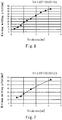
- Fig. 6 is a graph showing a relation between the thickness of the plate material and the minimum welding pitch in a case where the resistance spot welding of the low-carbon steel (e.g., S10C) is performed.
- Fig. 7 is a graph showing a relation between the thickness of the plate material and the minimum welding pitch in a case where the resistance spot welding of medium-carbon steel (e.g., S20C, S35C, S45C) or low-alloy steel (e.g., SNCM439, SCM435) is performed.
- the low-carbon steel is defined as steel with a carbon content (mass percentage concentration) that is less than 0.20%.
- the medium-carbon steel is defined as steel with a carbon content that is equal to or more than 0.20% and equal to or less than 0.6%.
- the low-alloy steel is defined as steel containing alloy elements with a content (mass percentage concentration) that is equal to or less than 5%, the alloy elements being other than iron and carbon.
- the minimum welding pitch means the lower limit value of the welding pitch which is required in a case where the pair of plate materials are welded (joined) to each other by only the resistance spot welding.
- the minimum welding pitch required in a case where the pair of plate materials are welded (joined) to each other by only the resistance spot welding is longer as the thickness of the plate material is increased.
- the minimum welding pitch required in a case where the pair of plate materials are welded (joined) to each other by only the resistance spot welding is shorter in a case where the plate materials are the low-carbon steel than in a case where the plate materials are the medium-carbon steel or the low-alloy steel.
- the reactive current is more easily generated as the thickness of the plate material is increased, and is less easily generated in the low-carbon steel than in the medium-carbon steel or the low-alloy steel.
- the upper limit value of the welding pitch is set to meet Y ⁇ - 1.4X 2 + 18.6X + 0.6 in a case where the plate materials are the low-carbon steel, and is set to meet Y ⁇ - 1.9X 2 + 25.5X + 2.1 in a case where the plate materials are the medium-carbon steel or the low-alloy steel.
- the controller 20 sets the welding pitch L between the friction stir spot weld J and each of the resistance spot welds W1, W2 to meet Y ⁇ - 1.4X 2 + 18.6X + 0.6 in a case where the plate materials 51, 52 are the low-carbon steel. Also, the controller 20 sets the welding pitch L between the friction stir spot weld J and each of the resistance spot welds W1, W2 to meet Y ⁇ - 1.9X 2 + 25.5X + 2.1 in a case where the plate materials 51, 52 are the medium-carbon steel or the low-alloy steel.
- the controller 20 sets the welding pitch L between the friction stir spot weld J and each of the resistance spot welds W1, W2 to a value which is larger than the sum of the radius of the resistance spot weld J and the radius of the friction stir spot weld W1(W2).
- the controller 20 sets the welding pitch L between the friction stir spot weld J and each of the resistance spot welds W1, W2 to a welding pitch with which the tensile shear strength in a case where a pair of friction stir spot weld and resistance spot weld are formed in the pair of plate materials is higher than that in a case where a pair of resistance spot welds are formed in the pair of plate materials.
- the welding pitch L between the spot welds (the resistance spot weld and the friction stir spot weld) can be reduced as a whole, while keeping a long distance between the resistance spot welds W1, W2. Since the distance between the resistance spot welds W1, W2 is made long and thereby the reactive current is suppressed, it becomes possible to prevent reduction of the welding strength, degradation of the external appearance quality, and non-uniformity of the welding strength. In addition, since the welding pitch L between the spot welds can be reduced as a whole, the joint strength and the stiffness of the joint structure 100 can be improved.
- the controller 20 sets the welding pitch L between the friction stir spot weld J and each of the resistance spot welds W1, W2 so that the tensile shear strength of the "resistance spot welding + friction stir spot welding" is higher than that of the "resistance spot welding + resistance spot welding". Therefore, it becomes possible to suitably prevent reduction of the welding strength due to the reactive current and improve the welding strength by reduction of the welding pitch, in the resistance spot welding. Further, the controller 20 sets the welding pitch L between the friction stir spot weld J and each of the resistance spot welds W1, W2 to a value which is larger than the sum of the radius of the resistance spot weld W1(W2) and the radius of the friction stir spot weld J.
- the present invention is not limited to the above-described embodiment, and its configurations may be changed, added or deleted.
- the welding pitch L between the friction stir spot weld J and the resistance spot weld W1 may be different from the welding pitch L between the friction stir spot weld J and the resistance spot weld W2.
- the friction stir spot weld J is provided on a straight line connecting the pair of resistance spot welds W1, W2 to each other, the friction stir spot weld J may be provided at a location that is between the pair of resistance spot welds, on a curved line extending in the extending direction of curved portions in a case where the lapped portions of the plate materials have the curved portions in a top plan view (when viewed from above).
- the displacement driving unit may move the workpiece with respect to the tool. Further the number of plate materials which are lapped to each other and are spot welded may be set to three or more.
Landscapes
- Engineering & Computer Science (AREA)
- Mechanical Engineering (AREA)
- Pressure Welding/Diffusion-Bonding (AREA)
- Resistance Welding (AREA)
Abstract
Description
- The present invention relates to a spot welding apparatus, a spot welding method, and a joint structure, in which a plurality of plate materials are lapped to each other and spot welded to each other.
- In assembly steps of an automobile, an aircraft, a railway vehicle, or the like, a plurality of plate materials are lapped to each other, and welded (joined) to each other by resistance spot welding, to manufacture a joint structure. To increase a stiffness of the joint structure, a welding (joining) pitch of resistance spot welds (resistance spot welded portions) may be reduced, and the number of welding spots (welding spotting points) may be increased. However, if spacing between the resistance spot welds is small in a case where the resistance spot welding is performed, a part of a welding current from a welding electrode flows to an adjacent resistance spot weld, and a reactive current is generated. If this reactive current is increased, the welding current flowing through portions to be spot welded is reduced, so that a desired welding (joining) strength cannot be obtained in some cases. In view of this,
Patent Literature 1 discloses that the reactive current is reduced by forming a slit to make discontinuity in at least a part of a region connecting a pair of resistance spot welds, of a pair of plate materials. - Patent Literature 1: Japanese Patent No.
5605405 - However, the method disclosed in
Patent Literature 1 has a problem that a plate material strength of a region that is in the vicinity of the slit is reduced, and the stiffness of the joint structure is reduced, although the welding strength of the resistance spot welds is high. Also, in methods other than the method disclosed inPatent Literature 1, the welding current may be set to be higher in view of the reactive current. However, if the welding current is increased, a rapid welding phenomenon occurs, and the material is scattered due to a pressure applied by the welding electrode. This may result in a reduced welding strength and a degraded external appearance quality. A frequency at which the reactive current is generated depends on the diameter of the resistance spot weld, or a contact state of the lapped plate materials (gap between the lapped plate materials). For this reason, if the welding pitch is reduced, non-uniformity of the welding strength occurs. - In view of the above-described circumstances, an object of the present invention is to provide a high joint strength and a stable quality while suppressing a reactive current in resistance spot welding.
- According to an aspect of the present invention, there is provided a spot welding apparatus which performs spot welding of a plurality of plate materials which are lapped to each other, the spot welding apparatus comprising: a displacement driving unit which displaces lapped portions of the plurality of plate materials and a tool relatively to each other; a rotation driving unit which rotates the tool; and a controller which controls the displacement driving unit and the rotation driving unit so that the tool is plunged into the lapped portions in a state in which the tool is rotated to perform friction stir spot welding, wherein the controller controls the displacement driving unit so that at least one friction stir spot weld is formed in a region of the lapped portions which is between a plurality of resistance spot welds formed by resistance spot welding.
- In accordance with this configuration, by forming the friction stir spot weld (friction stir spot welded portion) in the region which is between the plurality of resistance spot welds (resistance spot welded portions), a welding pitch between the spot welds (the resistance spot weld and the friction stir spot weld) can be reduced as a whole, while keeping a long distance between the resistance spot welds. Since a distance between the resistance spot welds is made long and thereby a reactive current is suppressed, it becomes possible to prevent reduction of a welding (joining) strength, degradation of an external appearance quality, and non-uniformity of the welding strength. In addition, since the welding pitch between the spot welds can be reduced as a whole, a high joint strength can be obtained.
- The controller may set a welding pitch between the at least one friction stir spot weld and each of the plurality of resistance spot welds to a welding pitch with which a tensile shear strength in a case where a pair of friction stir spot weld and resistance spot weld are formed in a pair of plate materials is higher than a tensile shear strength in a case where a pair of resistance spot welds are formed in the pair of plate materials.
- In accordance with this configuration, it becomes possible to suitably prevent reduction of the welding strength due to the reactive current and improve the welding strength by reduction of the welding pitch, in the resistance spot welding.
- The plurality of plate materials may be steel materials, and in a case where a welding pitch between the at least one friction stir spot weld and each of the plurality of resistance spot welds is Y and a thickness of each of a pair of plate materials is X, the controller may set the welding pitch to meet Y ≦ - 1.4X2 + 18.6X + 0.6 in a case where the pair of plate materials are low-carbon steel, and the controller may set the welding pitch to meet Y ≦ - 1.9X2 + 25.5X + 2.1 in a case where the pair of plate materials are medium-carbon steel or low-alloy steel.
- In accordance with this configuration, it becomes possible to suitably prevent reduction of the welding strength due to the reactive current and improve the welding strength by reduction of the welding pitch, in the resistance spot welding.
- The controller may set a welding pitch between the at least one friction stir spot weld and each of the plurality of resistance spot welds to a value which is larger than a sum of a radius of each of the plurality of resistance spot welds and a radius of the at least one friction stir spot weld.
- In accordance with this configuration, it becomes possible to prevent a situation in which the friction stir spot weld and the resistance spot weld overlap with each other, and thereby a total welding (joining) area is reduced. As a result, the welding strength can be effectively improved.
- According to another aspect of the present invention, there is provided a spot welding method which performs spot welding of a pair of plate materials which are lapped to each other, the spot welding method comprising: performing resistance spot welding of lapped portions of the pair of plate materials to form a plurality of resistance spot welds; and performing friction stir spot welding of a region of the lapped portions which is between the plurality of resistance spot welds to form at least one friction stir spot weld.
- According to a further aspect of the present invention, there is provided a joint structure formed by performing spot welding of a pair of plate materials which are lapped to each other, the joint structure comprising: a plurality of resistance spot welds formed in lapped portions of the pair of plate materials; and at least one friction stir spot weld formed in a region of the lapped portions which is between the plurality of resistance spot welds.
- In accordance with the present invention, it becomes possible to provide a high joint strength and a stable quality while suppressing a reactive current in resistance spot welding.
-
-
Fig. 1 is a view schematically showing the configuration of a friction stir spot welding device of a spot welding apparatus according to an embodiment. -
Fig. 2 is a cross-sectional view for explaining a resistance spot welding step. -
Fig. 3 is a cross-sectional view for explaining a friction stir spot welding step. -
Fig. 4 is a plan view of major constituents of a joint structure. -
Fig. 5 is a graph showing a relation between a welding pitch and a tensile shear strength in a tensile shear test. -
Fig. 6 is a graph showing a relation between a thickness of a plate material and a minimum welding pitch in a case where resistance spot welding of low-carbon steel is performed. -
Fig. 7 is a graph showing a relation between the thickness of the plate material and the minimum welding pitch in a case where resistance spot welding of medium-carbon steel or low-alloy steel is performed. - Hereinafter, the embodiment will be described with reference to the drawings.
-
Fig. 1 is a view schematically showing the configuration of a friction stirspot welding device 2 of aspot welding apparatus 1 according to the embodiment. As shown inFig. 1 , aworkpiece 50 includes a pair ofplate materials spot welding device 2 is configured to perform spot welding oflapped portions 50a of the pair ofplate materials spot welding device 2 includes abase 11, amovable member 12 mounted on thebase 11, and atool retaining member 13 protruding from themovable member 12 toward theworkpiece 50. Themovable member 12 is mounted on thebase 11 so that themovable member 12 is slidable along the axis line of thetool retaining member 13. Thetool retaining member 13 is rotatable around its axis line. Atool 10 is detachably mounted on the tip end portion of thetool retaining member 13. Acurved frame 14 which is curved in a substantially-L shape is secured to thebase 11. Thecurved frame 14 extends to a location at which its tip end portion faces thetool 10. Asupport base 15 is provided at the tip end portion of thecurved frame 14 to support theworkpiece 50. - The
base 11 is provided with a linearmotion driving unit 16 which slides themovable member 12 in the axial direction of thetool retaining member 13. The linearmotion driving unit 16 slides themovable member 12 to advance and retract thetool 10 with respect to theworkpiece 50. Themovable member 12 is provided with arotation driving unit 17 which rotates thetool retaining member 13 around the axis line of thetool retaining member 13. Therotation driving unit 17 rotates thetool retaining member 13 to rotate thetool 10. An articulated (multi-joint)robot 18 is mounted on thebase 11. The articulatedrobot 18 displaces thebase 11 to displace thetool 10 to a desired position with respect to theworkpiece 50. In brief, the linearmotion driving unit 16 and thearticulated robot 18 serve as adisplacement driving unit 19 which displaces theworkpiece 50 and thetool 10 relatively to each other. - The friction stir
spot welding device 2 includes acontroller 20 which controls the linearmotion driving unit 16, therotation driving unit 17, and the articulatedrobot 18. Thecontroller 20 may be a single control unit with an integrated function, or a plurality of control units with distributed functions. Thecontroller 20 includes a processor, a volatile memory, a non-volatile memory, an I/O interface, or the like. In response to a command input via the I/O interface by an input device (e.g., computer or teaching pendant) which is not shown, the processor of thecontroller 12 performs calculations (computations) by use of the volatile memory based on an operation program stored in the non-volatile memory, and thecontroller 12 communicates with therotation driving unit 17 and thedisplacement driving unit 19 via the I/O interface. The friction stirspot welding device 2 performs friction stir spot welding in such a way that thecontroller 20 controls therotation driving unit 17 and thedisplacement driving unit 19 to plunge thetool 10 into thelapped portions 50a of the pair ofplate materials tool 10 is rotated, and to stir and plasticize a portion softened by friction heat, of thelapped portions 50a. -
Fig. 2 is a cross-sectional view for explaining a resistance spot welding step. As shown inFig. 2 , thespot welding apparatus 1 of the present embodiment further includes a resistancespot welding device 3. The resistancespot welding device 3 includes a pair ofwelding electrodes welding electrodes spot welding device 3 performs resistance welding of thelapped portions 50a of the pair ofplate materials portions 50a are sandwiched between the pair ofwelding electrodes lapped portions 50a, with a predetermined gap between the resistance spot welds W1, W2. In this way, the pair ofplate materials -
Fig. 3 is a cross-sectional view for explaining a friction stir spot welding step. As shown inFig. 3 , the friction stirspot welding device 2 forms at least one friction stir spot weld (friction stir welded portion) J in a region R which is between the plurality of resistance spot welds W1, W2, of thelapped portions 50a of the pair ofplate materials plate materials tool 10 includes atool body 10a, and apin 10b protruding from the center of thetool body 10a toward theworkpiece 50 and having a diameter smaller than that of thetool body 10a. - In the friction stir spot welding, the controller 20 (see
Fig. 1 ) controls therotation driving unit 17 so that the rotation speed of thetool 10 reaches a target rotation speed. In this state, thecontroller 20 controls the linearmotion driving unit 16 to displace thetool 10 so that thepin 10b presses thelapped portions 50a of theworkpiece 50. Then, thepin 10b of thetool 10 softens the lappedportions 50a of theworkpiece 50 by friction heat. Thepin 10b stirs and plasticizes a softenedportion 50b. After passage of a predetermined welding time (plunge time of thepin 10b), thecontroller 20 causes the linearmotion driving unit 16 to displace thetool 10 in a direction in which thetool 10 is pulled out (drawn out) of theworkpiece 50. After thetool 10 is pulled out of theworkpiece 50, the softenedportion 50b is cooled and cured (hardened), and thus the friction stir spot weld J is formed. In the friction stir spot welding, no electric current is applied to theplate materials lapped portions 50a of the pair ofplate materials joint structure 100 is formed. -
Fig. 4 is a plan view of major constituents of thejoint structure 100. As shown inFigs. 3 and4 , thejoint structure 100 is formed by performing spot welding of the pair ofplate materials joint structure 100 is used in a structure body such as an automobile, an aircraft, a railway vehicle, or the like. Thejoint structure 100 includes the pair of resistance spot welds W1, W2 formed in thelapped portions 50a of the pair ofplate materials -
Fig. 5 is a graph showing a relation between the welding pitch and a tensile shear strength in a tensile shear test. In this tensile shear test, as a pair of plate materials constituting the joint structure, DP 980 steel plates (tensile strength 980MPa) which were low-carbon steel were used, and the thickness of each of the plate materials was set to 1.2mm. Black plots ofFig. 5 indicate results (hereinafter will be referred to as "resistance spot welding + friction stir spot welding") of the tensile shear test conducted for the joint structure including one resistance spot weld and one friction stir spot weld. A solid line is an approximate line of these black plots. White plots ofFig. 5 indicate results (hereinafter will be referred to as "resistance spot welding + resistance spot welding") of the tensile shear test conducted for the joint structure including two resistance spot welds. A broken line is an approximate line of these white plots. - As can be seen from
Fig. 5 , in a case where the welding pitch is in a range of 6mm to 20mm (the welding pitch is 6mm or more and 20mm or less), the tensile shear strength of the "resistance spot welding + friction stir spot welding" is higher than that of the "resistance spot welding + resistance spot welding". In a case where the welding pitch is excessively short, a welding pitch between the resistance spot weld and the friction stir spot weld is shorter than a sum of a radius of the resistance spot weld and a radius of the friction stir spot weld, the resistance spot weld and the friction stir spot weld overlap with each other, and thereby a total welding (joining) area is reduced. As a result, the effect of improving the joint strength is reduced. In view of this, the welding pitch is preferably set to 6mm or more to prevent the resistance spot weld and the friction stir spot weld from overlapping with each other. Specifically, a lower limit value of the welding pitch with which the tensile shear strength of the "resistance spot welding + friction stir spot welding" is higher than that of the "resistance spot welding + resistance spot welding" depends on the radius of the resistance spot weld and the radius of the friction stir spot weld. InFig. 5 , each of the plots at which the welding pitch is 0mm indicates the tensile shear strength at a single point. In this case, the tensile shear strength at one point of the resistance spot weld is higher than that of the friction stir spot weld. - In a case where the welding pitch is long, the reactive current generated by flow dividing of the welding current, during the resistance spot welding, is reduced. For this reason, in this case, the tensile shear strength of the "resistance spot welding + resistance spot welding" is higher than that of the "resistance spot welding + friction stir spot welding". However, in a case where the welding pitch is 20mm or less, the reactive current is increased in the "resistance spot welding + resistance spot welding". For this reason, in this case, the tensile shear strength of the "resistance spot welding + friction stir spot welding" is higher than that of the "resistance spot welding + resistance spot welding". For example, in a comparison of a fracture state after the tensile shear test in a case where the welding pitch was 10mm, it was observed that in the "resistance spot welding + resistance spot welding", the resistance spot weld at a second spotting point had a diameter smaller than that of the resistance spot weld at a first spotting point, and an interface fracture was formed, while it was observed that in the "resistance spot welding + friction stir spot welding", a base material (base metal) fracture was formed. In view of this, in the joint structure comprising the plate materials formed by the low-carbon steel and each having a thickness of 1.2mm, the welding pitch between the friction stir spot weld and the resistance spot weld is preferably set to a value that is 20mm or less. An upper limit value of the welding pitch with which the tensile shear strength of the "resistance spot welding + friction stir spot welding" is higher than that of the "resistance spot welding + resistance spot welding" is varied depending on the material quality and thickness of the plate materials. This will be described below.
-
Fig. 6 is a graph showing a relation between the thickness of the plate material and the minimum welding pitch in a case where the resistance spot welding of the low-carbon steel (e.g., S10C) is performed.Fig. 7 is a graph showing a relation between the thickness of the plate material and the minimum welding pitch in a case where the resistance spot welding of medium-carbon steel (e.g., S20C, S35C, S45C) or low-alloy steel (e.g., SNCM439, SCM435) is performed. The low-carbon steel is defined as steel with a carbon content (mass percentage concentration) that is less than 0.20%. The medium-carbon steel is defined as steel with a carbon content that is equal to or more than 0.20% and equal to or less than 0.6%. The low-alloy steel is defined as steel containing alloy elements with a content (mass percentage concentration) that is equal to or less than 5%, the alloy elements being other than iron and carbon. The minimum welding pitch means the lower limit value of the welding pitch which is required in a case where the pair of plate materials are welded (joined) to each other by only the resistance spot welding. InFig. 6 , a solid line is an approximate line of black plots. This solid line is represented by Y = - 1.4X2 + 18.6X + 0.6 in a case where the welding pitch is Y(mm) and the thickness is X (mm). InFig. 7 , a solid line is an approximate line of black plots. This solid line is represented by Y = - 1.9X2 + 25.5X + 2.1 in a case where the welding pitch is Y(mm) and the thickness is X (mm). - As shown in
Figs. 6 and 7 , the minimum welding pitch required in a case where the pair of plate materials are welded (joined) to each other by only the resistance spot welding is longer as the thickness of the plate material is increased. The minimum welding pitch required in a case where the pair of plate materials are welded (joined) to each other by only the resistance spot welding is shorter in a case where the plate materials are the low-carbon steel than in a case where the plate materials are the medium-carbon steel or the low-alloy steel. In summary, the reactive current is more easily generated as the thickness of the plate material is increased, and is less easily generated in the low-carbon steel than in the medium-carbon steel or the low-alloy steel. - A white plot indicating the upper limit value (20mm) of the welding pitch with which the tensile shear strength of the "resistance spot welding + friction stir spot welding" was higher than that of the "resistance spot welding + resistance spot welding" in the test result (low-carbon steel; thickness 1.2mm) of
Fig. 5 is added toFig. 6 . This white plot is roughly located on the solid line (Y = - 1.4X2 + 18.6X + 0.6) of the graph. Therefore, in the joint structure in which the resistance spot weld and the friction stir spot weld are adjacent to each other, preferably, the upper limit value of the welding pitch is set to meet Y ≦ - 1.4X2 + 18.6X + 0.6 in a case where the plate materials are the low-carbon steel, and is set to meet Y ≦ - 1.9X2 + 25.5X + 2.1 in a case where the plate materials are the medium-carbon steel or the low-alloy steel. - From the above fact, the
controller 20 sets the welding pitch L between the friction stir spot weld J and each of the resistance spot welds W1, W2 to meet Y ≦ - 1.4X2 + 18.6X + 0.6 in a case where theplate materials controller 20 sets the welding pitch L between the friction stir spot weld J and each of the resistance spot welds W1, W2 to meet Y ≦ - 1.9X2 + 25.5X + 2.1 in a case where theplate materials controller 20 sets the welding pitch L between the friction stir spot weld J and each of the resistance spot welds W1, W2 to a value which is larger than the sum of the radius of the resistance spot weld J and the radius of the friction stir spot weld W1(W2). Thecontroller 20 sets the welding pitch L between the friction stir spot weld J and each of the resistance spot welds W1, W2 to a welding pitch with which the tensile shear strength in a case where a pair of friction stir spot weld and resistance spot weld are formed in the pair of plate materials is higher than that in a case where a pair of resistance spot welds are formed in the pair of plate materials. - In accordance with the above-described configuration, by forming the friction stir spot weld J in the region R which is between the resistance spot welds W1, W2, the welding pitch L between the spot welds (the resistance spot weld and the friction stir spot weld) can be reduced as a whole, while keeping a long distance between the resistance spot welds W1, W2. Since the distance between the resistance spot welds W1, W2 is made long and thereby the reactive current is suppressed, it becomes possible to prevent reduction of the welding strength, degradation of the external appearance quality, and non-uniformity of the welding strength. In addition, since the welding pitch L between the spot welds can be reduced as a whole, the joint strength and the stiffness of the
joint structure 100 can be improved. - The
controller 20 sets the welding pitch L between the friction stir spot weld J and each of the resistance spot welds W1, W2 so that the tensile shear strength of the "resistance spot welding + friction stir spot welding" is higher than that of the "resistance spot welding + resistance spot welding". Therefore, it becomes possible to suitably prevent reduction of the welding strength due to the reactive current and improve the welding strength by reduction of the welding pitch, in the resistance spot welding. Further, thecontroller 20 sets the welding pitch L between the friction stir spot weld J and each of the resistance spot welds W1, W2 to a value which is larger than the sum of the radius of the resistance spot weld W1(W2) and the radius of the friction stir spot weld J. This makes it possible to prevent a situation in which the friction stir spot weld J and each of the resistance spot welds W1, W2 overlap with each other, and thereby a total welding (joining) area is reduced. As a result, the welding strength can be effectively improved. - The present invention is not limited to the above-described embodiment, and its configurations may be changed, added or deleted. For example, the welding pitch L between the friction stir spot weld J and the resistance spot weld W1 may be different from the welding pitch L between the friction stir spot weld J and the resistance spot weld W2. Although in the example of
Fig. 4 , the friction stir spot weld J is provided on a straight line connecting the pair of resistance spot welds W1, W2 to each other, the friction stir spot weld J may be provided at a location that is between the pair of resistance spot welds, on a curved line extending in the extending direction of curved portions in a case where the lapped portions of the plate materials have the curved portions in a top plan view (when viewed from above). The displacement driving unit may move the workpiece with respect to the tool. Further the number of plate materials which are lapped to each other and are spot welded may be set to three or more. -
- 1
- spot welding apparatus
- 2
- friction stir spot welding device
- 3
- resistance spot welding device
- 10
- tool
- 17
- rotation driving unit
- 19
- displacement driving unit
- 20
- controller
- 50a
- lapped portions
- 51, 52
- plate materials
- 100
- joint structure
- J
- friction stir spot weld
- L
- welding pitch
- W1, W2
- resistance spot welds
Claims (9)
- A spot welding apparatus which performs spot welding of a plurality of plate materials which are lapped to each other, the spot welding apparatus comprising:a displacement driving unit which displaces lapped portions of the plurality of plate materials and a tool relatively to each other;a rotation driving unit which rotates the tool; anda controller which controls the displacement driving unit and the rotation driving unit so that the tool is plunged into the lapped portions in a state in which the tool is rotated to perform friction stir spot welding,wherein the controller controls the displacement driving unit so that at least one friction stir spot weld is formed in a region of the lapped portions which is between a plurality of resistance spot welds formed by resistance spot welding.
- The spot welding apparatus according to claim 1,
wherein the controller sets a welding pitch between the at least one friction stir spot weld and each of the plurality of resistance spot welds to a welding pitch with which a tensile shear strength in a case where a pair of friction stir spot weld and resistance spot weld are formed in the plurality of plate materials is higher than a tensile shear strength in a case where a pair of resistance spot welds are formed in the plurality of plate materials. - The spot welding apparatus according to claim 1 or 2,
wherein the plurality of plate materials are steel materials,
wherein in a case where a welding pitch between the at least one friction stir spot weld and each of the plurality of resistance spot welds is Y and a thickness of each of a pair of plate materials is X,
the controller sets the welding pitch to meet Y ≦ - 1.4X2 + 18.6X + 0.6 in a case where the plate materials are low-carbon steel, and
the controller sets the welding pitch to meet Y ≦ - 1.9X2 + 25.5X + 2.1 in a case where the plate materials are medium-carbon steel or low-alloy steel. - The spot welding apparatus according to any one of claims 1 to 3,
wherein the controller sets a welding pitch between the at least one friction stir spot weld and each of the plurality of resistance spot welds to a value which is larger than a sum of a radius of each of the plurality of resistance spot welds and a radius of the at least one friction stir spot weld. - A spot welding method which performs spot welding of a plurality of plate materials which are lapped to each other, the spot welding method comprising:performing resistance spot welding of lapped portions of the plurality of plate materials to form a plurality of resistance spot welds; andperforming friction stir spot welding of a region of the lapped portions which is between the plurality of resistance spot welds to form at least one friction stir spot weld.
- The spot welding method according to claim 5,
wherein a welding pitch between the at least one friction stir spot weld and each of the plurality of resistance spot welds is set to a welding pitch with which a tensile shear strength in a case where a pair of friction stir spot weld and resistance spot weld are formed in the plurality of plate materials is higher than a tensile shear strength in a case where a pair of resistance spot welds are formed in the plurality of plate materials. - The spot welding method according to claim 5 or 6,
wherein the plurality of plate materials are steel materials,
wherein in a case where a welding pitch between the at least one friction stir spot weld and each of the plurality of resistance spot welds is Y and a thickness of each of a pair of plate materials is X,
the welding pitch is set to meet Y ≦ - 1.4X2 + 18.6X + 0.6 in a case where the plate materials are low-carbon steel, and
the welding pitch is set to meet Y ≦ - 1.9X2 + 25.5X + 2.1 in a case where the plate materials are medium-carbon steel or low-alloy steel. - The spot welding method according to any one of claims 5 to 7,
wherein a welding pitch between the at least one friction stir spot weld and each of the plurality of resistance spot welds is set to a value which is larger than a sum of a radius of each of the plurality of resistance spot welds and a radius of the at least one friction stir spot weld. - A joint structure formed by performing spot welding of a plurality of plate materials which are lapped to each other, the joint structure comprising:a plurality of resistance spot welds formed in lapped portions of the plurality of plate materials; andat least one friction stir spot weld formed in a region of the lapped portions which is between the plurality of resistance spot welds.
Applications Claiming Priority (2)
| Application Number | Priority Date | Filing Date | Title |
|---|---|---|---|
| JP2016090611A JP6393707B2 (en) | 2016-04-28 | 2016-04-28 | Spot joining apparatus, spot joining method and joint structure |
| PCT/JP2017/016816 WO2017188399A1 (en) | 2016-04-28 | 2017-04-27 | Spot welding device, spot welding method, and joint structure |
Publications (3)
| Publication Number | Publication Date |
|---|---|
| EP3450080A1 true EP3450080A1 (en) | 2019-03-06 |
| EP3450080A4 EP3450080A4 (en) | 2019-12-04 |
| EP3450080B1 EP3450080B1 (en) | 2023-10-04 |
Family
ID=60160780
Family Applications (1)
| Application Number | Title | Priority Date | Filing Date |
|---|---|---|---|
| EP17789680.0A Active EP3450080B1 (en) | 2016-04-28 | 2017-04-27 | Spot welding device and spot welding method |
Country Status (6)
| Country | Link |
|---|---|
| US (1) | US11040413B2 (en) |
| EP (1) | EP3450080B1 (en) |
| JP (1) | JP6393707B2 (en) |
| KR (1) | KR102207831B1 (en) |
| CN (1) | CN109070264B (en) |
| WO (1) | WO2017188399A1 (en) |
Families Citing this family (13)
| Publication number | Priority date | Publication date | Assignee | Title |
|---|---|---|---|---|
| EP3981537B1 (en) * | 2017-09-04 | 2025-03-12 | Kawasaki Jukogyo Kabushiki Kaisha | Method for operating double-action friction stir welding device, and double-action friction stir welding device |
| KR102477654B1 (en) | 2018-10-11 | 2022-12-14 | 카와사키 주코교 카부시키 카이샤 | Friction stir welding device, its operation method and joint structure |
| US10442029B1 (en) * | 2019-04-10 | 2019-10-15 | King Saud University | Method of friction stir spot welding |
| JP7223651B2 (en) | 2019-07-01 | 2023-02-16 | 川崎重工業株式会社 | Welding system and its operation method |
| KR102230872B1 (en) * | 2019-12-19 | 2021-03-24 | 주식회사 포스코 | Manufacturing method of titanium ring for electro-deposition drum and titanium ring manufactured thereof |
| CN111468849B (en) * | 2020-04-15 | 2021-07-13 | 广东省资源综合利用研究所 | Rare earth magnetic disk welding process |
| US11958126B2 (en) * | 2020-10-06 | 2024-04-16 | GE Precision Healthcare LLC | Containers for retaining anesthetic agent and manufacturing methods thereof |
| WO2022145382A1 (en) * | 2020-12-28 | 2022-07-07 | 川崎重工業株式会社 | Joining method, joined body, and joining device |
| JP7524122B2 (en) * | 2021-03-30 | 2024-07-29 | 川崎重工業株式会社 | Joined structure and joining method |
| KR20240000449A (en) * | 2021-04-28 | 2024-01-02 | 도요 고한 가부시키가이샤 | Surface treatment foil for current collector and method of manufacturing same |
| US12454024B2 (en) * | 2021-05-14 | 2025-10-28 | Kawasaki Jukogyo Kabushiki Kaisha | Joining method and joined body |
| JP7353329B2 (en) * | 2021-07-16 | 2023-09-29 | 本田技研工業株式会社 | Welding device and method for friction stir welding and resistance welding |
| US12599987B2 (en) * | 2021-08-31 | 2026-04-14 | Jfe Steel Corporation | Friction stir spot welded joint and production method therefor, and friction stir spot welding method |
Family Cites Families (18)
| Publication number | Priority date | Publication date | Assignee | Title |
|---|---|---|---|---|
| JPS5285278A (en) | 1976-01-09 | 1977-07-15 | Nippon Oil Co Ltd | Production of polyolefin |
| JP2580029B2 (en) * | 1989-03-20 | 1997-02-12 | ファナック株式会社 | Variable-pitch spot welding gun device for welding robot |
| EP1346792A1 (en) * | 2002-03-21 | 2003-09-24 | H.A. Schlatter Ag | Welding unit |
| JP2004276724A (en) * | 2003-03-14 | 2004-10-07 | Tokyu Car Corp | Car body for rolling stock and its manufacturing method |
| JP3860153B2 (en) * | 2003-09-12 | 2006-12-20 | 川崎重工業株式会社 | Joint structure |
| JP2006167747A (en) * | 2004-12-15 | 2006-06-29 | Honda Motor Co Ltd | Welding apparatus and processing method |
| DE102005001341B3 (en) * | 2005-01-11 | 2006-10-05 | Kuka Schweissanlagen Gmbh | Method and device for electric spot welding |
| JP5044162B2 (en) * | 2006-07-31 | 2012-10-10 | トヨタ自動車株式会社 | Dissimilar metal joint structure and dissimilar metal joining method |
| US20080149687A1 (en) * | 2006-12-22 | 2008-06-26 | Garnett Mark D | Weld Inspection Optimizer |
| JP2009202828A (en) * | 2008-02-29 | 2009-09-10 | Mazda Motor Corp | Manufacturing method and manufacturing line of vehicle body |
| JP5521421B2 (en) * | 2009-07-21 | 2014-06-11 | スズキ株式会社 | Double welding gun structure |
| JP5391046B2 (en) * | 2009-12-07 | 2014-01-15 | 川崎重工業株式会社 | Friction stir welding apparatus and joining method thereof |
| US8052029B1 (en) * | 2010-09-01 | 2011-11-08 | GM Global Technology Operations LLC | Method of calibrating a friction stir spot welding system |
| JP5605405B2 (en) | 2012-08-07 | 2014-10-15 | 新日鐵住金株式会社 | Resistance welded joint |
| KR101382319B1 (en) * | 2012-12-17 | 2014-04-08 | 현대자동차 주식회사 | Twin spot welding apparatus |
| CN103170752A (en) * | 2013-04-09 | 2013-06-26 | 上海电机学院 | Friction stir spot welding (FSSW) device of resistor and method thereof |
| JP5960655B2 (en) * | 2013-08-08 | 2016-08-02 | 株式会社神戸製鋼所 | Spot laser combined weld joint |
| DE102016206759A1 (en) * | 2015-07-21 | 2017-01-26 | Ford Global Technologies, Llc | A method for joining at least two metal workpieces lying on each other |
-
2016
- 2016-04-28 JP JP2016090611A patent/JP6393707B2/en not_active Expired - Fee Related
-
2017
- 2017-04-27 KR KR1020187033701A patent/KR102207831B1/en not_active Expired - Fee Related
- 2017-04-27 WO PCT/JP2017/016816 patent/WO2017188399A1/en not_active Ceased
- 2017-04-27 CN CN201780025929.1A patent/CN109070264B/en not_active Expired - Fee Related
- 2017-04-27 EP EP17789680.0A patent/EP3450080B1/en active Active
- 2017-04-27 US US16/097,496 patent/US11040413B2/en not_active Expired - Fee Related
Also Published As
| Publication number | Publication date |
|---|---|
| EP3450080B1 (en) | 2023-10-04 |
| KR102207831B1 (en) | 2021-01-26 |
| CN109070264A (en) | 2018-12-21 |
| US20190143442A1 (en) | 2019-05-16 |
| US11040413B2 (en) | 2021-06-22 |
| CN109070264B (en) | 2021-08-20 |
| WO2017188399A1 (en) | 2017-11-02 |
| EP3450080A4 (en) | 2019-12-04 |
| JP6393707B2 (en) | 2018-09-19 |
| KR20180132154A (en) | 2018-12-11 |
| JP2017196649A (en) | 2017-11-02 |
Similar Documents
| Publication | Publication Date | Title |
|---|---|---|
| EP3450080B1 (en) | Spot welding device and spot welding method | |
| US12064831B2 (en) | Joining system, and method for operating same | |
| JP5261984B2 (en) | Resistance spot welding method | |
| US20090261146A1 (en) | Donor material technology for friction stir welding | |
| JP2019136748A (en) | Resistance spot welding method | |
| JP5045238B2 (en) | Resistance spot welding method | |
| JP7278300B2 (en) | FRICTION STIR WELDING APPARATUS, OPERATION METHOD THEREOF, AND JOINT STRUCTURE | |
| WO2015037652A1 (en) | Resistance spot welding method and welded structure | |
| JP2007268604A (en) | Resistance spot welding method | |
| JP5609966B2 (en) | Resistance spot welding method | |
| JP2005193298A (en) | Resistance welding electrode, resistance welding method and welded structure | |
| KR102747977B1 (en) | Friction stir spot welding device and method for operating same | |
| JP5906618B2 (en) | Resistance spot welding method | |
| JP2007029981A (en) | Method for suppressing propagation of crack, and welded joint structure | |
| Chou et al. | Application of robotic welding technology to the continuity plate weld within a steel built-up box column in buildings | |
| CN109475969B (en) | Resistance spot welding electrode and use of the electrode | |
| JP6794945B2 (en) | Joining method | |
| EP4706862A1 (en) | Friction stir spot welding tool | |
| Saeheaw | Regression Modeling and Process Analysis of Plug and Spot Welds Used in Automotive Body Panel Assembly | |
| JP2020121334A (en) | Resistance spot welding method | |
| De Backer | Robotic friction stir welding for flexible production | |
| WO2025253900A1 (en) | Friction stir spot-welding device and friction stir spot-welding method | |
| WO2023243151A1 (en) | Method for predicting resistance spot welding spatter generation, resistance spot welding method, and method for manufacturing welded member | |
| WO2025075060A1 (en) | Friction stir spot welding method and friction stir spot welding device | |
| JP2008142731A (en) | Laser welding method, laser welding apparatus, and laser lap weld joint |
Legal Events
| Date | Code | Title | Description |
|---|---|---|---|
| STAA | Information on the status of an ep patent application or granted ep patent |
Free format text: STATUS: THE INTERNATIONAL PUBLICATION HAS BEEN MADE |
|
| PUAI | Public reference made under article 153(3) epc to a published international application that has entered the european phase |
Free format text: ORIGINAL CODE: 0009012 |
|
| STAA | Information on the status of an ep patent application or granted ep patent |
Free format text: STATUS: REQUEST FOR EXAMINATION WAS MADE |
|
| 17P | Request for examination filed |
Effective date: 20181128 |
|
| AK | Designated contracting states |
Kind code of ref document: A1 Designated state(s): AL AT BE BG CH CY CZ DE DK EE ES FI FR GB GR HR HU IE IS IT LI LT LU LV MC MK MT NL NO PL PT RO RS SE SI SK SM TR |
|
| AX | Request for extension of the european patent |
Extension state: BA ME |
|
| DAV | Request for validation of the european patent (deleted) | ||
| DAX | Request for extension of the european patent (deleted) | ||
| A4 | Supplementary search report drawn up and despatched |
Effective date: 20191107 |
|
| RIC1 | Information provided on ipc code assigned before grant |
Ipc: B23K 103/04 20060101ALN20191031BHEP Ipc: B23K 11/11 20060101ALI20191031BHEP Ipc: B23K 28/02 20140101ALI20191031BHEP Ipc: B23K 11/16 20060101ALI20191031BHEP Ipc: B23K 101/00 20060101ALN20191031BHEP Ipc: B23K 20/12 20060101AFI20191031BHEP |
|
| STAA | Information on the status of an ep patent application or granted ep patent |
Free format text: STATUS: EXAMINATION IS IN PROGRESS |
|
| 17Q | First examination report despatched |
Effective date: 20220302 |
|
| GRAP | Despatch of communication of intention to grant a patent |
Free format text: ORIGINAL CODE: EPIDOSNIGR1 |
|
| RIC1 | Information provided on ipc code assigned before grant |
Ipc: B23K 103/04 20060101ALN20230327BHEP Ipc: B23K 101/00 20060101ALN20230327BHEP Ipc: B23K 11/16 20060101ALI20230327BHEP Ipc: B23K 28/02 20140101ALI20230327BHEP Ipc: B23K 11/11 20060101ALI20230327BHEP Ipc: B23K 20/12 20060101AFI20230327BHEP |
|
| STAA | Information on the status of an ep patent application or granted ep patent |
Free format text: STATUS: GRANT OF PATENT IS INTENDED |
|
| RIC1 | Information provided on ipc code assigned before grant |
Ipc: B23K 103/04 20060101ALN20230404BHEP Ipc: B23K 101/00 20060101ALN20230404BHEP Ipc: B23K 11/16 20060101ALI20230404BHEP Ipc: B23K 28/02 20140101ALI20230404BHEP Ipc: B23K 11/11 20060101ALI20230404BHEP Ipc: B23K 20/12 20060101AFI20230404BHEP |
|
| INTG | Intention to grant announced |
Effective date: 20230504 |
|
| GRAS | Grant fee paid |
Free format text: ORIGINAL CODE: EPIDOSNIGR3 |
|
| GRAA | (expected) grant |
Free format text: ORIGINAL CODE: 0009210 |
|
| STAA | Information on the status of an ep patent application or granted ep patent |
Free format text: STATUS: THE PATENT HAS BEEN GRANTED |
|
| AK | Designated contracting states |
Kind code of ref document: B1 Designated state(s): AL AT BE BG CH CY CZ DE DK EE ES FI FR GB GR HR HU IE IS IT LI LT LU LV MC MK MT NL NO PL PT RO RS SE SI SK SM TR |
|
| REG | Reference to a national code |
Ref country code: GB Ref legal event code: FG4D |
|
| REG | Reference to a national code |
Ref country code: CH Ref legal event code: EP |
|
| REG | Reference to a national code |
Ref country code: IE Ref legal event code: FG4D |
|
| REG | Reference to a national code |
Ref country code: DE Ref legal event code: R096 Ref document number: 602017074936 Country of ref document: DE |
|
| REG | Reference to a national code |
Ref country code: LT Ref legal event code: MG9D |
|
| REG | Reference to a national code |
Ref country code: NL Ref legal event code: MP Effective date: 20231004 |
|
| REG | Reference to a national code |
Ref country code: AT Ref legal event code: MK05 Ref document number: 1617252 Country of ref document: AT Kind code of ref document: T Effective date: 20231004 |
|
| PG25 | Lapsed in a contracting state [announced via postgrant information from national office to epo] |
Ref country code: NL Free format text: LAPSE BECAUSE OF FAILURE TO SUBMIT A TRANSLATION OF THE DESCRIPTION OR TO PAY THE FEE WITHIN THE PRESCRIBED TIME-LIMIT Effective date: 20231004 |
|
| PG25 | Lapsed in a contracting state [announced via postgrant information from national office to epo] |
Ref country code: GR Free format text: LAPSE BECAUSE OF FAILURE TO SUBMIT A TRANSLATION OF THE DESCRIPTION OR TO PAY THE FEE WITHIN THE PRESCRIBED TIME-LIMIT Effective date: 20240105 |
|
| PG25 | Lapsed in a contracting state [announced via postgrant information from national office to epo] |
Ref country code: IS Free format text: LAPSE BECAUSE OF FAILURE TO SUBMIT A TRANSLATION OF THE DESCRIPTION OR TO PAY THE FEE WITHIN THE PRESCRIBED TIME-LIMIT Effective date: 20240204 |
|
| PG25 | Lapsed in a contracting state [announced via postgrant information from national office to epo] |
Ref country code: LT Free format text: LAPSE BECAUSE OF FAILURE TO SUBMIT A TRANSLATION OF THE DESCRIPTION OR TO PAY THE FEE WITHIN THE PRESCRIBED TIME-LIMIT Effective date: 20231004 |
|
| PG25 | Lapsed in a contracting state [announced via postgrant information from national office to epo] |
Ref country code: AT Free format text: LAPSE BECAUSE OF FAILURE TO SUBMIT A TRANSLATION OF THE DESCRIPTION OR TO PAY THE FEE WITHIN THE PRESCRIBED TIME-LIMIT Effective date: 20231004 |
|
| PG25 | Lapsed in a contracting state [announced via postgrant information from national office to epo] |
Ref country code: ES Free format text: LAPSE BECAUSE OF FAILURE TO SUBMIT A TRANSLATION OF THE DESCRIPTION OR TO PAY THE FEE WITHIN THE PRESCRIBED TIME-LIMIT Effective date: 20231004 |
|
| PG25 | Lapsed in a contracting state [announced via postgrant information from national office to epo] |
Ref country code: LT Free format text: LAPSE BECAUSE OF FAILURE TO SUBMIT A TRANSLATION OF THE DESCRIPTION OR TO PAY THE FEE WITHIN THE PRESCRIBED TIME-LIMIT Effective date: 20231004 Ref country code: IS Free format text: LAPSE BECAUSE OF FAILURE TO SUBMIT A TRANSLATION OF THE DESCRIPTION OR TO PAY THE FEE WITHIN THE PRESCRIBED TIME-LIMIT Effective date: 20240204 Ref country code: GR Free format text: LAPSE BECAUSE OF FAILURE TO SUBMIT A TRANSLATION OF THE DESCRIPTION OR TO PAY THE FEE WITHIN THE PRESCRIBED TIME-LIMIT Effective date: 20240105 Ref country code: ES Free format text: LAPSE BECAUSE OF FAILURE TO SUBMIT A TRANSLATION OF THE DESCRIPTION OR TO PAY THE FEE WITHIN THE PRESCRIBED TIME-LIMIT Effective date: 20231004 Ref country code: BG Free format text: LAPSE BECAUSE OF FAILURE TO SUBMIT A TRANSLATION OF THE DESCRIPTION OR TO PAY THE FEE WITHIN THE PRESCRIBED TIME-LIMIT Effective date: 20240104 Ref country code: AT Free format text: LAPSE BECAUSE OF FAILURE TO SUBMIT A TRANSLATION OF THE DESCRIPTION OR TO PAY THE FEE WITHIN THE PRESCRIBED TIME-LIMIT Effective date: 20231004 Ref country code: PT Free format text: LAPSE BECAUSE OF FAILURE TO SUBMIT A TRANSLATION OF THE DESCRIPTION OR TO PAY THE FEE WITHIN THE PRESCRIBED TIME-LIMIT Effective date: 20240205 |
|
| PG25 | Lapsed in a contracting state [announced via postgrant information from national office to epo] |
Ref country code: SE Free format text: LAPSE BECAUSE OF FAILURE TO SUBMIT A TRANSLATION OF THE DESCRIPTION OR TO PAY THE FEE WITHIN THE PRESCRIBED TIME-LIMIT Effective date: 20231004 Ref country code: RS Free format text: LAPSE BECAUSE OF FAILURE TO SUBMIT A TRANSLATION OF THE DESCRIPTION OR TO PAY THE FEE WITHIN THE PRESCRIBED TIME-LIMIT Effective date: 20231004 Ref country code: PL Free format text: LAPSE BECAUSE OF FAILURE TO SUBMIT A TRANSLATION OF THE DESCRIPTION OR TO PAY THE FEE WITHIN THE PRESCRIBED TIME-LIMIT Effective date: 20231004 Ref country code: NO Free format text: LAPSE BECAUSE OF FAILURE TO SUBMIT A TRANSLATION OF THE DESCRIPTION OR TO PAY THE FEE WITHIN THE PRESCRIBED TIME-LIMIT Effective date: 20240104 Ref country code: LV Free format text: LAPSE BECAUSE OF FAILURE TO SUBMIT A TRANSLATION OF THE DESCRIPTION OR TO PAY THE FEE WITHIN THE PRESCRIBED TIME-LIMIT Effective date: 20231004 Ref country code: HR Free format text: LAPSE BECAUSE OF FAILURE TO SUBMIT A TRANSLATION OF THE DESCRIPTION OR TO PAY THE FEE WITHIN THE PRESCRIBED TIME-LIMIT Effective date: 20231004 |
|
| REG | Reference to a national code |
Ref country code: DE Ref legal event code: R097 Ref document number: 602017074936 Country of ref document: DE |
|
| PG25 | Lapsed in a contracting state [announced via postgrant information from national office to epo] |
Ref country code: DK Free format text: LAPSE BECAUSE OF FAILURE TO SUBMIT A TRANSLATION OF THE DESCRIPTION OR TO PAY THE FEE WITHIN THE PRESCRIBED TIME-LIMIT Effective date: 20231004 |
|
| PG25 | Lapsed in a contracting state [announced via postgrant information from national office to epo] |
Ref country code: CZ Free format text: LAPSE BECAUSE OF FAILURE TO SUBMIT A TRANSLATION OF THE DESCRIPTION OR TO PAY THE FEE WITHIN THE PRESCRIBED TIME-LIMIT Effective date: 20231004 |
|
| PG25 | Lapsed in a contracting state [announced via postgrant information from national office to epo] |
Ref country code: SK Free format text: LAPSE BECAUSE OF FAILURE TO SUBMIT A TRANSLATION OF THE DESCRIPTION OR TO PAY THE FEE WITHIN THE PRESCRIBED TIME-LIMIT Effective date: 20231004 |
|
| PG25 | Lapsed in a contracting state [announced via postgrant information from national office to epo] |
Ref country code: SM Free format text: LAPSE BECAUSE OF FAILURE TO SUBMIT A TRANSLATION OF THE DESCRIPTION OR TO PAY THE FEE WITHIN THE PRESCRIBED TIME-LIMIT Effective date: 20231004 Ref country code: SK Free format text: LAPSE BECAUSE OF FAILURE TO SUBMIT A TRANSLATION OF THE DESCRIPTION OR TO PAY THE FEE WITHIN THE PRESCRIBED TIME-LIMIT Effective date: 20231004 Ref country code: RO Free format text: LAPSE BECAUSE OF FAILURE TO SUBMIT A TRANSLATION OF THE DESCRIPTION OR TO PAY THE FEE WITHIN THE PRESCRIBED TIME-LIMIT Effective date: 20231004 Ref country code: IT Free format text: LAPSE BECAUSE OF FAILURE TO SUBMIT A TRANSLATION OF THE DESCRIPTION OR TO PAY THE FEE WITHIN THE PRESCRIBED TIME-LIMIT Effective date: 20231004 Ref country code: EE Free format text: LAPSE BECAUSE OF FAILURE TO SUBMIT A TRANSLATION OF THE DESCRIPTION OR TO PAY THE FEE WITHIN THE PRESCRIBED TIME-LIMIT Effective date: 20231004 Ref country code: DK Free format text: LAPSE BECAUSE OF FAILURE TO SUBMIT A TRANSLATION OF THE DESCRIPTION OR TO PAY THE FEE WITHIN THE PRESCRIBED TIME-LIMIT Effective date: 20231004 Ref country code: CZ Free format text: LAPSE BECAUSE OF FAILURE TO SUBMIT A TRANSLATION OF THE DESCRIPTION OR TO PAY THE FEE WITHIN THE PRESCRIBED TIME-LIMIT Effective date: 20231004 |
|
| PLBE | No opposition filed within time limit |
Free format text: ORIGINAL CODE: 0009261 |
|
| STAA | Information on the status of an ep patent application or granted ep patent |
Free format text: STATUS: NO OPPOSITION FILED WITHIN TIME LIMIT |
|
| 26N | No opposition filed |
Effective date: 20240705 |
|
| PG25 | Lapsed in a contracting state [announced via postgrant information from national office to epo] |
Ref country code: SI Free format text: LAPSE BECAUSE OF FAILURE TO SUBMIT A TRANSLATION OF THE DESCRIPTION OR TO PAY THE FEE WITHIN THE PRESCRIBED TIME-LIMIT Effective date: 20231004 |
|
| PG25 | Lapsed in a contracting state [announced via postgrant information from national office to epo] |
Ref country code: SI Free format text: LAPSE BECAUSE OF FAILURE TO SUBMIT A TRANSLATION OF THE DESCRIPTION OR TO PAY THE FEE WITHIN THE PRESCRIBED TIME-LIMIT Effective date: 20231004 |
|
| REG | Reference to a national code |
Ref country code: DE Ref legal event code: R119 Ref document number: 602017074936 Country of ref document: DE |
|
| PG25 | Lapsed in a contracting state [announced via postgrant information from national office to epo] |
Ref country code: MC Free format text: LAPSE BECAUSE OF FAILURE TO SUBMIT A TRANSLATION OF THE DESCRIPTION OR TO PAY THE FEE WITHIN THE PRESCRIBED TIME-LIMIT Effective date: 20231004 |
|
| PG25 | Lapsed in a contracting state [announced via postgrant information from national office to epo] |
Ref country code: MC Free format text: LAPSE BECAUSE OF FAILURE TO SUBMIT A TRANSLATION OF THE DESCRIPTION OR TO PAY THE FEE WITHIN THE PRESCRIBED TIME-LIMIT Effective date: 20231004 |
|
| REG | Reference to a national code |
Ref country code: CH Ref legal event code: PL |
|
| PG25 | Lapsed in a contracting state [announced via postgrant information from national office to epo] |
Ref country code: LU Free format text: LAPSE BECAUSE OF NON-PAYMENT OF DUE FEES Effective date: 20240427 |
|
| GBPC | Gb: european patent ceased through non-payment of renewal fee |
Effective date: 20240427 |
|
| REG | Reference to a national code |
Ref country code: BE Ref legal event code: MM Effective date: 20240430 |
|
| PG25 | Lapsed in a contracting state [announced via postgrant information from national office to epo] |
Ref country code: LU Free format text: LAPSE BECAUSE OF NON-PAYMENT OF DUE FEES Effective date: 20240427 |
|
| PG25 | Lapsed in a contracting state [announced via postgrant information from national office to epo] |
Ref country code: DE Free format text: LAPSE BECAUSE OF NON-PAYMENT OF DUE FEES Effective date: 20241105 |
|
| PG25 | Lapsed in a contracting state [announced via postgrant information from national office to epo] |
Ref country code: BE Free format text: LAPSE BECAUSE OF NON-PAYMENT OF DUE FEES Effective date: 20240430 |
|
| PG25 | Lapsed in a contracting state [announced via postgrant information from national office to epo] |
Ref country code: GB Free format text: LAPSE BECAUSE OF NON-PAYMENT OF DUE FEES Effective date: 20240427 |
|
| PG25 | Lapsed in a contracting state [announced via postgrant information from national office to epo] |
Ref country code: FR Free format text: LAPSE BECAUSE OF NON-PAYMENT OF DUE FEES Effective date: 20240430 |
|
| PG25 | Lapsed in a contracting state [announced via postgrant information from national office to epo] |
Ref country code: GB Free format text: LAPSE BECAUSE OF NON-PAYMENT OF DUE FEES Effective date: 20240427 Ref country code: FR Free format text: LAPSE BECAUSE OF NON-PAYMENT OF DUE FEES Effective date: 20240430 Ref country code: DE Free format text: LAPSE BECAUSE OF NON-PAYMENT OF DUE FEES Effective date: 20241105 Ref country code: BE Free format text: LAPSE BECAUSE OF NON-PAYMENT OF DUE FEES Effective date: 20240430 Ref country code: CH Free format text: LAPSE BECAUSE OF NON-PAYMENT OF DUE FEES Effective date: 20240430 |
|
| PG25 | Lapsed in a contracting state [announced via postgrant information from national office to epo] |
Ref country code: IE Free format text: LAPSE BECAUSE OF NON-PAYMENT OF DUE FEES Effective date: 20240427 |
|
| PG25 | Lapsed in a contracting state [announced via postgrant information from national office to epo] |
Ref country code: CY Free format text: LAPSE BECAUSE OF FAILURE TO SUBMIT A TRANSLATION OF THE DESCRIPTION OR TO PAY THE FEE WITHIN THE PRESCRIBED TIME-LIMIT; INVALID AB INITIO Effective date: 20170427 |
|
| PG25 | Lapsed in a contracting state [announced via postgrant information from national office to epo] |
Ref country code: HU Free format text: LAPSE BECAUSE OF FAILURE TO SUBMIT A TRANSLATION OF THE DESCRIPTION OR TO PAY THE FEE WITHIN THE PRESCRIBED TIME-LIMIT; INVALID AB INITIO Effective date: 20170427 |
|
| PG25 | Lapsed in a contracting state [announced via postgrant information from national office to epo] |
Ref country code: FI Free format text: LAPSE BECAUSE OF FAILURE TO SUBMIT A TRANSLATION OF THE DESCRIPTION OR TO PAY THE FEE WITHIN THE PRESCRIBED TIME-LIMIT Effective date: 20231004 |
|
| PG25 | Lapsed in a contracting state [announced via postgrant information from national office to epo] |
Ref country code: TR Free format text: LAPSE BECAUSE OF FAILURE TO SUBMIT A TRANSLATION OF THE DESCRIPTION OR TO PAY THE FEE WITHIN THE PRESCRIBED TIME-LIMIT Effective date: 20231004 |