EP3450040A1 - Cooler tube, method for producing this cooler tube and mould wheel for use in this method - Google Patents
Cooler tube, method for producing this cooler tube and mould wheel for use in this method Download PDFInfo
- Publication number
- EP3450040A1 EP3450040A1 EP17188451.3A EP17188451A EP3450040A1 EP 3450040 A1 EP3450040 A1 EP 3450040A1 EP 17188451 A EP17188451 A EP 17188451A EP 3450040 A1 EP3450040 A1 EP 3450040A1
- Authority
- EP
- European Patent Office
- Prior art keywords
- strip material
- flat strip
- wavy
- cooler tube
- openings
- Prior art date
- Legal status (The legal status is an assumption and is not a legal conclusion. Google has not performed a legal analysis and makes no representation as to the accuracy of the status listed.)
- Withdrawn
Links
Images



Classifications
-
- B—PERFORMING OPERATIONS; TRANSPORTING
- B21—MECHANICAL METAL-WORKING WITHOUT ESSENTIALLY REMOVING MATERIAL; PUNCHING METAL
- B21C—MANUFACTURE OF METAL SHEETS, WIRE, RODS, TUBES, PROFILES OR LIKE SEMI-MANUFACTURED PRODUCTS OTHERWISE THAN BY ROLLING; AUXILIARY OPERATIONS USED IN CONNECTION WITH METAL-WORKING WITHOUT ESSENTIALLY REMOVING MATERIAL
- B21C37/00—Manufacture of metal sheets, rods, wire, tubes, profiles or like semi-manufactured products, not otherwise provided for; Manufacture of tubes of special shape
- B21C37/06—Manufacture of metal sheets, rods, wire, tubes, profiles or like semi-manufactured products, not otherwise provided for; Manufacture of tubes of special shape of tubes or metal hoses; Combined procedures for making tubes, e.g. for making multi-wall tubes
- B21C37/15—Making tubes of special shape; Making tube fittings
- B21C37/151—Making tubes with multiple passages
-
- B—PERFORMING OPERATIONS; TRANSPORTING
- B21—MECHANICAL METAL-WORKING WITHOUT ESSENTIALLY REMOVING MATERIAL; PUNCHING METAL
- B21C—MANUFACTURE OF METAL SHEETS, WIRE, RODS, TUBES, PROFILES OR LIKE SEMI-MANUFACTURED PRODUCTS OTHERWISE THAN BY ROLLING; AUXILIARY OPERATIONS USED IN CONNECTION WITH METAL-WORKING WITHOUT ESSENTIALLY REMOVING MATERIAL
- B21C37/00—Manufacture of metal sheets, rods, wire, tubes, profiles or like semi-manufactured products, not otherwise provided for; Manufacture of tubes of special shape
- B21C37/06—Manufacture of metal sheets, rods, wire, tubes, profiles or like semi-manufactured products, not otherwise provided for; Manufacture of tubes of special shape of tubes or metal hoses; Combined procedures for making tubes, e.g. for making multi-wall tubes
- B21C37/065—Manufacture of metal sheets, rods, wire, tubes, profiles or like semi-manufactured products, not otherwise provided for; Manufacture of tubes of special shape of tubes or metal hoses; Combined procedures for making tubes, e.g. for making multi-wall tubes starting from a specific blank, e.g. tailored blank
-
- B—PERFORMING OPERATIONS; TRANSPORTING
- B21—MECHANICAL METAL-WORKING WITHOUT ESSENTIALLY REMOVING MATERIAL; PUNCHING METAL
- B21D—WORKING OR PROCESSING OF SHEET METAL OR METAL TUBES, RODS OR PROFILES WITHOUT ESSENTIALLY REMOVING MATERIAL; PUNCHING METAL
- B21D53/00—Making other particular articles
- B21D53/02—Making other particular articles heat exchangers or parts thereof, e.g. radiators, condensers fins, headers
-
- B—PERFORMING OPERATIONS; TRANSPORTING
- B21—MECHANICAL METAL-WORKING WITHOUT ESSENTIALLY REMOVING MATERIAL; PUNCHING METAL
- B21D—WORKING OR PROCESSING OF SHEET METAL OR METAL TUBES, RODS OR PROFILES WITHOUT ESSENTIALLY REMOVING MATERIAL; PUNCHING METAL
- B21D53/00—Making other particular articles
- B21D53/02—Making other particular articles heat exchangers or parts thereof, e.g. radiators, condensers fins, headers
- B21D53/06—Making other particular articles heat exchangers or parts thereof, e.g. radiators, condensers fins, headers of metal tubes
-
- F—MECHANICAL ENGINEERING; LIGHTING; HEATING; WEAPONS; BLASTING
- F28—HEAT EXCHANGE IN GENERAL
- F28D—HEAT-EXCHANGE APPARATUS, NOT PROVIDED FOR IN ANOTHER SUBCLASS, IN WHICH THE HEAT-EXCHANGE MEDIA DO NOT COME INTO DIRECT CONTACT
- F28D1/00—Heat-exchange apparatus having stationary conduit assemblies for one heat-exchange medium only, the media being in contact with different sides of the conduit wall, in which the other heat-exchange medium is a large body of fluid, e.g. domestic or motor car radiators
- F28D1/02—Heat-exchange apparatus having stationary conduit assemblies for one heat-exchange medium only, the media being in contact with different sides of the conduit wall, in which the other heat-exchange medium is a large body of fluid, e.g. domestic or motor car radiators with heat-exchange conduits immersed in the body of fluid
- F28D1/03—Heat-exchange apparatus having stationary conduit assemblies for one heat-exchange medium only, the media being in contact with different sides of the conduit wall, in which the other heat-exchange medium is a large body of fluid, e.g. domestic or motor car radiators with heat-exchange conduits immersed in the body of fluid with plate-like or laminated conduits
- F28D1/0391—Heat-exchange apparatus having stationary conduit assemblies for one heat-exchange medium only, the media being in contact with different sides of the conduit wall, in which the other heat-exchange medium is a large body of fluid, e.g. domestic or motor car radiators with heat-exchange conduits immersed in the body of fluid with plate-like or laminated conduits a single plate being bent to form one or more conduits
-
- F—MECHANICAL ENGINEERING; LIGHTING; HEATING; WEAPONS; BLASTING
- F28—HEAT EXCHANGE IN GENERAL
- F28F—DETAILS OF HEAT-EXCHANGE AND HEAT-TRANSFER APPARATUS, OF GENERAL APPLICATION
- F28F1/00—Tubular elements; Assemblies of tubular elements
- F28F1/02—Tubular elements of cross-section which is non-circular
- F28F1/022—Tubular elements of cross-section which is non-circular with multiple channels
-
- F—MECHANICAL ENGINEERING; LIGHTING; HEATING; WEAPONS; BLASTING
- F28—HEAT EXCHANGE IN GENERAL
- F28F—DETAILS OF HEAT-EXCHANGE AND HEAT-TRANSFER APPARATUS, OF GENERAL APPLICATION
- F28F1/00—Tubular elements; Assemblies of tubular elements
- F28F1/10—Tubular elements and assemblies thereof with means for increasing heat-transfer area, e.g. with fins, with projections, with recesses
- F28F1/40—Tubular elements and assemblies thereof with means for increasing heat-transfer area, e.g. with fins, with projections, with recesses the means being only inside the tubular element
-
- F—MECHANICAL ENGINEERING; LIGHTING; HEATING; WEAPONS; BLASTING
- F28—HEAT EXCHANGE IN GENERAL
- F28F—DETAILS OF HEAT-EXCHANGE AND HEAT-TRANSFER APPARATUS, OF GENERAL APPLICATION
- F28F1/00—Tubular elements; Assemblies of tubular elements
- F28F1/10—Tubular elements and assemblies thereof with means for increasing heat-transfer area, e.g. with fins, with projections, with recesses
- F28F1/12—Tubular elements and assemblies thereof with means for increasing heat-transfer area, e.g. with fins, with projections, with recesses the means being only outside the tubular element
- F28F1/126—Tubular elements and assemblies thereof with means for increasing heat-transfer area, e.g. with fins, with projections, with recesses the means being only outside the tubular element consisting of zig-zag shaped fins
- F28F1/128—Fins with openings, e.g. louvered fins
-
- F—MECHANICAL ENGINEERING; LIGHTING; HEATING; WEAPONS; BLASTING
- F28—HEAT EXCHANGE IN GENERAL
- F28F—DETAILS OF HEAT-EXCHANGE AND HEAT-TRANSFER APPARATUS, OF GENERAL APPLICATION
- F28F3/00—Plate-like or laminated elements; Assemblies of plate-like or laminated elements
- F28F3/02—Elements or assemblies thereof with means for increasing heat-transfer area, e.g. with fins, with recesses, with corrugations
- F28F3/025—Elements or assemblies thereof with means for increasing heat-transfer area, e.g. with fins, with recesses, with corrugations the means being corrugated, plate-like elements
- F28F3/027—Elements or assemblies thereof with means for increasing heat-transfer area, e.g. with fins, with recesses, with corrugations the means being corrugated, plate-like elements with openings, e.g. louvered corrugated fins; Assemblies of corrugated strips
Definitions
- the present invention relates to a cooler tube according to the preamble of claim 1, a method for producing such a cooler tube according to claim 5, a mould wheel for use in this method according to claim 9 and a preferred use of the cooler tube according to claim 14.
- a charge air cooler tube requires a suitable balance between high heat transfer coefficient, compressive strength and jacket and turbulator surface. These specifications determine the present design and manufacture of a charge air cooler tube in which the cooler jacket is manufactured separately from the turbulator made of a 'thicker' material or conversely the turbulator is manufactured separately from the cooler jacket made of 'thinner' material and both components are joined together subsequently.
- a heat exchanger constructed of two components allows no reduction in the fabrication time and in addition no reduction in the material thickness of each of the components so that no weight reduction is achieved.
- German Patent Application DE 10 205 043 093 A1 for example is a cooler tube in which two flat strip materials of different thickness are used for the separate construction of cooler jacket and turbulator (swirler)
- the Japanese Patent Application JPH 10 193 085 A and also the European Patent Application EP 2 388 656 A2 disclose a cooler tube whose cooler jacket and also turbulator is folded from a single continuous flat strip material.
- these only use smooth turbulators which are not suitable for a higher heat dissipation over a shorter distance.
- Differently designed turbulators are known for example from the Japanese Patent Applications JP 6 313 691 A and JP 11 101 586 A .
- a cooler tube is made of a continuous flat strip material which is folded into at least one elongated loop, which surrounds a closed cavity and which runs in the cavity in a wavy manner, wherein individual cooling channels are formed by contacting the loop and a wavy portion is formed from a respective edge region of the flat strip material and the loop is formed from the interposed centre region of the flat strip material.
- the loop of the flat strip material has a higher material thickness than a wavy portion.
- a cooler tube designed in such a manner can be produced in a particularly simple manner from a single continuous flat-strip material and is also particularly light as a result of the weight-reduced turbulator. As a result of its reduced material thickness, this can additionally have more corrugations so that the capacity of the cooler tube is overall improved.
- this alternatively or additionally has alternative or additional openings, preferably regularly arranged opening patterns.
- the capacity of the cooler tube is also increased by the turbulence-generating openings which act like a standard offset panel in a turbulator.
- the material thickness of the flat strip material can be achieved in this case in a simple manner in the moulding process of the cooler tube by stretching and/or perforation of the edge zones.
- the openings are designed to be polygonal and/or slot-like and are preferably arranged spatially offset with respect to one another.
- a polygonal design of the openings allows a particularly good turbulence of the fluid stream not only at the edges of an opening however formed, but also at the corners thereof which provide for a secure flow separation.
- Slot-like openings are particularly strong on turbulence as a result of the separation length of their edges.
- the slot-like openings preferably in this case run in the longitudinal and/or transverse direction of at least one cooling channel so that a particularly efficient turbulence is obtained which is required for better contact of the cooling channel walls.
- the flat strip material has lamellae in the wavy portion which allows the specific guiding of the fluid stream beyond the pure openings and increases the turbulence.
- the cooler tube here preferably has regularly arranged lamella patterns so that a wide-area turbulence is ensured.
- the preceding object is also solved by a method for producing the described cooler tube in which respective edge zones of a continuous flat strip material are folded in a wavy manner and an interposed centre region of the flat strip material is folded in an elongated loop shape around a wavy portion so that these form individual cooling channels by contacting the loop, characterized in that the edge zones of the flat strip material are stretched before or during the wavy folding so that these have a smaller material thickness than the centre region thereof and/or are previously provided with openings, preferably with opening patterns.
- the advantage of this method can in particular be seen in that by means of a skilful selection and ordering of the process steps, only a single workpiece is required to obtained the cooler tube according to the invention.
- the method according to the invention is particularly simple and efficient and the manufacture of a cooler tube is extremely cost-effective.
- a significant weight reduction of the cooler tube fabricated therefrom can be achieved.
- a portion to be folded in a wavy manner is previously provided with lamellae, preferably with lamella patterns in order to enable a specific and preferably wide-area guiding of the fluid stream.
- the lamellae can be attached in this process step for example by stamping rollers or dies known per se.
- the flat strip material is provided with notches to form fold edges, in particular in its centre region, with the result that the folding process is significantly simplified without making the method of manufacture itself more complicated. This is because these notches can be produced by stamping rollers or dies known per se, ideally together with the openings in the flat band material.
- a wavy portion is formed with a mould wheel which is pressed into the flat strip material and rolled therein.
- a mould wheel can in particular be rolled in a running flat material strand, which enables a particularly efficient and simple processing of the strand before cutting into individual cooler tubes to be folded.
- openings and/or lamellae can be produced simultaneously in the flat band material.
- a stretching of the material can be performed by using the mould wheel.
- a mould wheel for use in a method of manufacture described for a cooler tube, having a cross-sectional profile configured to be wavy when viewed in the circumferential direction and projections and /or recesses arranged regularly along the circumference thereof for pressing correspondingly moulded openings and/or lamellae into the flat strip material.
- the mould wheel or wheels of a last moulding station before the folding process of the flat strip material can in this case for example hav side teeth which attach the openings in the flat strip material and/or produce offsets in the material which are suitable for making the fluid stream turbulent.
- the projections and/or recesses are arranged on at least one of the bilateral flanks of the wavy cross-sectional profile. It is thus possible to process both flanks of one corrugation at the same time which additionally allows a matched shaping and arrangement of embossings which ensures particularly good turbulence.
- the projections and/or recesses are designed to be polygonal and/or elongated and are preferably arranged spatially offset with respect to one another with the result that correspondingly shaped openings can be produced with or without lamellae positioned thereon, which ensure a flow separation at their edges and in particular at their corners.
- the elongated projections and/or recesses are aligned in the running direction or transversely to the running direction of the mould wheel, with the result that particularly efficient turbulence is achieved with the consequence of higher heat transfer at a cooling channel wall.
- the elongated projections and/or recesses are formed for pressing lamella-reinforced openings which enables a simultaneous turbulence as a result of flow separation edges and also specific guiding of the fluid stream.
- opening-free embossings in the flat strip material such as, for example, spherical or cubic offsets which bring about a flow separation.
- a cooler tube fabricated in such a manner should preferably be used as a cooler or condenser, in particular a charge air cooler for an internal combustion engine of a vehicle.
- cooler tube of the previously described type as or in a cooler or condenser, in particular as a charge air cooler for an internal combustion engine of a vehicle.
- FIG. 1a shows a perspective view of a part of the cooler tube 1 according to the invention.
- the cooler tube 1 is produced from a flat strip material 2, the edge zones of which on both sides are formed into wavy portions 6, 6' and run in a cavity 4 which is formed by a loop 3 of the flat strip material 2 which in turn is produced from the centre region 8 thereof. Together with the inner walls of the loop 3, the wavy portions 6, 6' form individual cooling channels 5 in which a fluid can flow.
- the wavy portions 6, 6' are provided with openings 9 arranged in a pattern, which in this embodiment of the cooler tube 1 are designed to be square. The acute-angled position and offset arrangement of these openings 9 in the inflow direction provides for sufficient turbulence of the fluid stream in the individual cooling channels 5.
- the cooler tube 1 consists of precisely one single piece of continuous flat strip material 2 which can be produced by skilful stretching, perforating and folding, rapidly, simply and cost-effectively.
- the number, arrangement and shape of the openings 9 can be selected as required.
- a cooler tube 1 having a low weight is produced since the portions 6, 6' running in a wavy manner have a reduced material thickness, here due to stretching and perforating than the loop 3 which borders them.
- Figure 1b shows a perspective view of the cooler tube 1 of Figure 1a with folded edge zones 7, 7'. Between these edge zones 7, 7' the flat strip material 2 has a centre region 8 which provides longitudinally running notches on the edges to be folded subsequently in order to make the folding process of the loop 3 simpler.
- FIG 1c shows a perspective view of the left edge zone 7 of the cooler tube 1 of Figure 1b .
- the openings 9 arranged in a pattern can again be seen, which openings serve on the one hand to produce turbulence of the fluid stream but on the other hand reduce the material thickness of this portion once again, this being already reduced by corresponding stretching, for example by flat rolling of the flat strip material 2 in the region to the left of the dot-dash line.
- a cooler tube 1 which is at the same time light and highly efficient can be produced by extremely simple processing of the flat strip material 2.
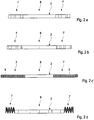
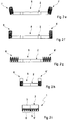
- Figures 2a to 2i show a sequence of the method for producing the cooler tube 1 of Figure 1a .
- Figure 2a initially shows the flat strip material 2 with its two edge zones 7, 7' and an interposed centre region 8.
- Figure 2b the edge zones 7, 7' are stretched, wherein the centre region 8 remains approximately the same.
- edge zones 7, 7' are perforated in Figure 2c , that is provided with openings 9 arranged in patterns before, in Figure 2d , these regions are folded in a wavy manner before being finally folded in the direction of the centre region 8 of the future cooler tube 1 in Figure 2e .
- the longitudinally running notches are applied in Figure 2d which supports the folding of the future edges.
- Figure 2f finally shows the future wavy portions 6, 6' folded towards the centre of the flat strip material 2, which are folded further towards the centre of the flat strip material 2 in Figures 2g and 2h , and finally received completely in the loop 3 thereby formed which together with this forms individual cooling channels 5.
- the method of manufacture is thus reasonably simple, efficient and cost-effective and results in a cooling tube 1 that is reduced in weight and additionally extremely effective.
- Figure 3a shows a perspective view of a cooler tube 1 according to the invention with slot-like openings 9' and lamellae 10 which are attached spatially offset with respect to one another in an already-folded edge zone 7 of a flat strip material 2.
- the combination of slot-like openings 9' and lamellae 10 produced at the same time allows particularly efficient turbulence of the fluid flowing in the subsequent cooling channels.
- the openings 9' and the relevant lamellae 10 in each case can be produced in a single fabrication step and for example applied by means of a mould wheel according to the invention over the length of the flat strip material 2.
- Figure 3b shows the section A-A through a corrugation of the future cooler tube of Figure 3a .
- the lamellae 10 are formed from the material of the slot-like openings 9' which is possible for example as a result of a corresponding stamping process.
- the arrangement of opening 9' and lamella 10 can be arranged on both flanks of a corrugation of the folded edge zone 7 in order to achieve the highest possible turbulence density of the fluid with thus increased heat exchange.
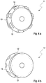
- Figure 4a shows a first mould wheel 11 according to the invention for use in the previously described method of manufacture of Figures 2a to 2i .
- the mould wheel 11 has projections 12 which are arranged offset with respect to one another on its bilateral flanks 13 and produces the combination of slot-like opening 9 and appurtenant lamella 10 of Figure 3b when it is rolled in the flat strip material 2.
- the cross-sectional profile of the rolling surface of the mould wheel 11 can be selected in precisely the same way as the projections 12 so that a specifically desired wave shape and therefore configuration of the cooling channels with openings and/or lamellae is produced.
- the cooling channels 5 can for example have a box-shaped, triangular or different wave form.
- the projections 12 of the mould wheel 11 must not necessarily form openings 9' but can merely be designed to produce spherical or cubic embossings which also produce turbulence.
- Figure 4b shows a second mould wheel 11' according to the invention for use in the method of manufacture of Figures 2a to 2i .
- this has a cross-sectional profile of its rolling surface provided with interior flanks 13 and is provided with recesses 12' arranged offset thereon, which for example produce the previously described embossings in the flat strip material 2 of the cooler tube of Figure 3b to be folded.
- These embossings are also conducive to the turbulence of a fluid flowing in the cooling channels and can be attached to the bilateral flanks of a corrugation of the edge zone 7.
- mould wheel 12, 12' allows a particularly simple and rapid as well as cost-effective folding and perforation of the edge zones 7, 7' of a flat strip material 2, which can be simultaneously stretched by the use of the mould wheel 12, 12'.
- the method of manufacture therefore only consists of the use of the mould wheel 12, 12' on the edge zones 7, 7' of the flat strip material 2, alternatively the application of notches to facilitate edge formation and the subsequent folding of the wavy portions 6, 6' into a loop 3 in order to produce a light and at the same time efficient cooler tube 1.
- Such a cooler tube 1 is characterized in particular by a high heat exchange capacity over shortest distances which mean that it can preferably be used as cooler and condenser, in particular as a charge air cooler for a small and high-performance internal combustion engine of a vehicle.
Landscapes
- Engineering & Computer Science (AREA)
- Mechanical Engineering (AREA)
- Physics & Mathematics (AREA)
- Thermal Sciences (AREA)
- General Engineering & Computer Science (AREA)
- Geometry (AREA)
- Heat-Exchange Devices With Radiators And Conduit Assemblies (AREA)
Abstract
Description
- The present invention relates to a cooler tube according to the preamble of
claim 1, a method for producing such a cooler tube according toclaim 5, a mould wheel for use in this method according toclaim 9 and a preferred use of the cooler tube according to claim 14. - Light and efficient heat exchangers which merely incur low investment costs are usually required. For example, a charge air cooler tube requires a suitable balance between high heat transfer coefficient, compressive strength and jacket and turbulator surface. These specifications determine the present design and manufacture of a charge air cooler tube in which the cooler jacket is manufactured separately from the turbulator made of a 'thicker' material or conversely the turbulator is manufactured separately from the cooler jacket made of 'thinner' material and both components are joined together subsequently.
- However, a heat exchanger constructed of two components allows no reduction in the fabrication time and in addition no reduction in the material thickness of each of the components so that no weight reduction is achieved. Known from the German
Patent Application DE 10 205 043 093 A1 for example is a cooler tube in which two flat strip materials of different thickness are used for the separate construction of cooler jacket and turbulator (swirler) - The Japanese Patent Application
JPH 10 193 085 A Patent Application EP 2 388 656 A2 on the other hand disclose a cooler tube whose cooler jacket and also turbulator is folded from a single continuous flat strip material. In addition to the lack of weight saving, it is also disadvantageous that these only use smooth turbulators which are not suitable for a higher heat dissipation over a shorter distance. Differently designed turbulators are known for example from the Japanese Patent ApplicationsJP 6 313 691 A JP 11 101 586 A - Specifically smaller, lighter and at the same time more powerful motors will require turbo- instead of water-cooled charge air coolers which also deliver the necessary cooling. Primarily a weight reduction and increase in efficiency of the cooler tubes is required for this.
- This problem is solved according to the invention by the subject matters of the
independent claims - The present invention is based on the general idea of producing a cooler tube from a single component instead of from two components as hitherto, the material thickness of which is suitably varied in the moulding process. The material thickness should be understood here as the material mass per unit volume. To this end, a cooler tube is made of a continuous flat strip material which is folded into at least one elongated loop, which surrounds a closed cavity and which runs in the cavity in a wavy manner, wherein individual cooling channels are formed by contacting the loop and a wavy portion is formed from a respective edge region of the flat strip material and the loop is formed from the interposed centre region of the flat strip material. According to the invention it is provided that the loop of the flat strip material has a higher material thickness than a wavy portion. A cooler tube designed in such a manner can be produced in a particularly simple manner from a single continuous flat-strip material and is also particularly light as a result of the weight-reduced turbulator. As a result of its reduced material thickness, this can additionally have more corrugations so that the capacity of the cooler tube is overall improved. According to the invention, in the wavy portion this alternatively or additionally has alternative or additional openings, preferably regularly arranged opening patterns. The capacity of the cooler tube is also increased by the turbulence-generating openings which act like a standard offset panel in a turbulator. The material thickness of the flat strip material can be achieved in this case in a simple manner in the moulding process of the cooler tube by stretching and/or perforation of the edge zones.
- In a preferred embodiment of the cooler tube it is provided in this case that the openings are designed to be polygonal and/or slot-like and are preferably arranged spatially offset with respect to one another. A polygonal design of the openings allows a particularly good turbulence of the fluid stream not only at the edges of an opening however formed, but also at the corners thereof which provide for a secure flow separation. Slot-like openings on the other hand are particularly strong on turbulence as a result of the separation length of their edges. As a result of the spatial offset thereof, ultimately a wide-area turbulence of the fluid can be accomplished in the cooler tube in a simple and effective manner. As required, the slot-like openings preferably in this case run in the longitudinal and/or transverse direction of at least one cooling channel so that a particularly efficient turbulence is obtained which is required for better contact of the cooling channel walls.
- In a further preferred embodiment of the cooler tube according to the invention, the flat strip material has lamellae in the wavy portion which allows the specific guiding of the fluid stream beyond the pure openings and increases the turbulence. The cooler tube here preferably has regularly arranged lamella patterns so that a wide-area turbulence is ensured.
- The preceding object is also solved by a method for producing the described cooler tube in which respective edge zones of a continuous flat strip material are folded in a wavy manner and an interposed centre region of the flat strip material is folded in an elongated loop shape around a wavy portion so that these form individual cooling channels by contacting the loop, characterized in that the edge zones of the flat strip material are stretched before or during the wavy folding so that these have a smaller material thickness than the centre region thereof and/or are previously provided with openings, preferably with opening patterns. The advantage of this method can in particular be seen in that by means of a skilful selection and ordering of the process steps, only a single workpiece is required to obtained the cooler tube according to the invention. As a result, the method according to the invention is particularly simple and efficient and the manufacture of a cooler tube is extremely cost-effective. At the same time, specifically due to the stretching and/or interruption of the flat strip material in its edge zones, a significant weight reduction of the cooler tube fabricated therefrom can be achieved.
- In a preferred configuration of the method according to the invention, it is provided that a portion to be folded in a wavy manner is previously provided with lamellae, preferably with lamella patterns in order to enable a specific and preferably wide-area guiding of the fluid stream. The lamellae can be attached in this process step for example by stamping rollers or dies known per se.
- In a further preferred embodiment of the method, it is provided that the flat strip material is provided with notches to form fold edges, in particular in its centre region, with the result that the folding process is significantly simplified without making the method of manufacture itself more complicated. This is because these notches can be produced by stamping rollers or dies known per se, ideally together with the openings in the flat band material.
- In a particularly preferred embodiment of the method according to the invention, it is provided that a wavy portion is formed with a mould wheel which is pressed into the flat strip material and rolled therein. Such a mould wheel can in particular be rolled in a running flat material strand, which enables a particularly efficient and simple processing of the strand before cutting into individual cooler tubes to be folded. In principle, it is naturally also possible to use entire series of mould wheels in order to produce the wavy portions. Depending on the configuration of the rolling surface of the mould wheel with projections and/or recesses, openings and/or lamellae can be produced simultaneously in the flat band material. Additionally or alternatively to stretching the edge zones for example by flat rolling, in the step of producing wavy sections, a stretching of the material can be performed by using the mould wheel.
- The preceding object is also solved by a mould wheel for use in a method of manufacture described for a cooler tube, having a cross-sectional profile configured to be wavy when viewed in the circumferential direction and projections and /or recesses arranged regularly along the circumference thereof for pressing correspondingly moulded openings and/or lamellae into the flat strip material. The mould wheel or wheels of a last moulding station before the folding process of the flat strip material can in this case for example hav side teeth which attach the openings in the flat strip material and/or produce offsets in the material which are suitable for making the fluid stream turbulent.
- In a preferred embodiment of the mould wheel according to the invention, it is provided that the projections and/or recesses are arranged on at least one of the bilateral flanks of the wavy cross-sectional profile. It is thus possible to process both flanks of one corrugation at the same time which additionally allows a matched shaping and arrangement of embossings which ensures particularly good turbulence.
- In a further particularly preferred embodiment of the mould wheel according to the invention, the projections and/or recesses are designed to be polygonal and/or elongated and are preferably arranged spatially offset with respect to one another with the result that correspondingly shaped openings can be produced with or without lamellae positioned thereon, which ensure a flow separation at their edges and in particular at their corners.
- In yet another preferred embodiment of the mould wheel according to the invention, it is additionally provided that the elongated projections and/or recesses are aligned in the running direction or transversely to the running direction of the mould wheel, with the result that particularly efficient turbulence is achieved with the consequence of higher heat transfer at a cooling channel wall.
- In yet another preferred embodiment of the mould wheel according to the invention, it is also provided that the elongated projections and/or recesses are formed for pressing lamella-reinforced openings which enables a simultaneous turbulence as a result of flow separation edges and also specific guiding of the fluid stream. In principle, however it is also possible to attach opening-free embossings in the flat strip material such as, for example, spherical or cubic offsets which bring about a flow separation.
- As a result of its comparatively low weight and its particularly high heat transmission capacity with low manufacturing costs at the same time, a cooler tube fabricated in such a manner should preferably be used as a cooler or condenser, in particular a charge air cooler for an internal combustion engine of a vehicle.
- Finally, the basic problem is also solved by the use of a cooler tube of the previously described type as or in a cooler or condenser, in particular as a charge air cooler for an internal combustion engine of a vehicle.
- Further important features and advantages of the invention are obtained from the subclaims, from the drawings and from the relevant description of the figures with reference to the drawings.
- It is understood that the features mentioned previously and to be explained further hereinafter can be used not only in the respectively given combination but also in other combinations or alone without departing from the scope of the present invention.
- Preferred exemplary embodiments of the invention are presented in the drawings and are explained in detail in the following description, where the same reference numbers relate to the same or similar or functionally the same components.
- In the figures, in each case schematically
- Fig. 1a
- shows a perspective view of a part of a cooler tube according to the invention;
- Fig. 1b
- shows a perspective view of the cooler tube of
Figure 1a with folded edge zones; - Fig. 1c
- shows a perspective view of the left edge zone of the cooler tube of
Figure 1b ; - Figs. 2a-2i
- shows a sequence of the process for producing the cooler tube of
Figure 1a ; - Fig. 3a
- shows a perspective view of a cooler tube to be folded according to the invention, with openings and lamellae;
- Fig. 3b
- shows the section A-A through a corrugation of the future cooler tube of
Figure 3a ; - Fig. 4a
- shows a first mould wheel according to the invention for use in the method of manufacture of
Figures 2a-2i ; - Fig. 4b
- shows a second mould wheel according to the invention for use in the method of manufacture of
Figures 2a-2i ; -
Figure 1a shows a perspective view of a part of thecooler tube 1 according to the invention. Thecooler tube 1 is produced from aflat strip material 2, the edge zones of which on both sides are formed intowavy portions 6, 6' and run in a cavity 4 which is formed by aloop 3 of theflat strip material 2 which in turn is produced from thecentre region 8 thereof. Together with the inner walls of theloop 3, thewavy portions 6, 6' formindividual cooling channels 5 in which a fluid can flow. Thewavy portions 6, 6' are provided withopenings 9 arranged in a pattern, which in this embodiment of thecooler tube 1 are designed to be square. The acute-angled position and offset arrangement of theseopenings 9 in the inflow direction provides for sufficient turbulence of the fluid stream in theindividual cooling channels 5. Thesections 6, 6' running in a wavy manner have a smaller material thickness than theloop 3 placed therearound since these were stretched before or during the folding whilst the material thickness of thecentre region 8 of theflat strip material 2 remains the same. Thus, thecooler tube 1 consists of precisely one single piece of continuousflat strip material 2 which can be produced by skilful stretching, perforating and folding, rapidly, simply and cost-effectively. The number, arrangement and shape of theopenings 9 can be selected as required. At the same time, acooler tube 1 having a low weight is produced since theportions 6, 6' running in a wavy manner have a reduced material thickness, here due to stretching and perforating than theloop 3 which borders them. -
Figure 1b shows a perspective view of thecooler tube 1 ofFigure 1a with foldededge zones 7, 7'. Between theseedge zones 7, 7' theflat strip material 2 has acentre region 8 which provides longitudinally running notches on the edges to be folded subsequently in order to make the folding process of theloop 3 simpler. -
Figure 1c shows a perspective view of theleft edge zone 7 of thecooler tube 1 ofFigure 1b . Here theopenings 9 arranged in a pattern can again be seen, which openings serve on the one hand to produce turbulence of the fluid stream but on the other hand reduce the material thickness of this portion once again, this being already reduced by corresponding stretching, for example by flat rolling of theflat strip material 2 in the region to the left of the dot-dash line. As a mirror image, the same applies to the right-hand edge zone 7' of theflat strip material 2. In this way, acooler tube 1 which is at the same time light and highly efficient can be produced by extremely simple processing of theflat strip material 2. -
Figures 2a to 2i show a sequence of the method for producing thecooler tube 1 ofFigure 1a .Figure 2a initially shows theflat strip material 2 with its twoedge zones 7, 7' and an interposedcentre region 8. InFigure 2b theedge zones 7, 7' are stretched, wherein thecentre region 8 remains approximately the same. - Finally the
edge zones 7, 7' are perforated inFigure 2c , that is provided withopenings 9 arranged in patterns before, inFigure 2d , these regions are folded in a wavy manner before being finally folded in the direction of thecentre region 8 of the futurecooler tube 1 inFigure 2e . The longitudinally running notches are applied inFigure 2d which supports the folding of the future edges.Figure 2f finally shows the futurewavy portions 6, 6' folded towards the centre of theflat strip material 2, which are folded further towards the centre of theflat strip material 2 inFigures 2g and 2h , and finally received completely in theloop 3 thereby formed which together with this formsindividual cooling channels 5. The method of manufacture is thus reasonably simple, efficient and cost-effective and results in acooling tube 1 that is reduced in weight and additionally extremely effective. -
Figure 3a shows a perspective view of acooler tube 1 according to the invention with slot-like openings 9' andlamellae 10 which are attached spatially offset with respect to one another in an already-foldededge zone 7 of aflat strip material 2. The combination of slot-like openings 9' andlamellae 10 produced at the same time allows particularly efficient turbulence of the fluid flowing in the subsequent cooling channels. In addition, the openings 9' and therelevant lamellae 10 in each case can be produced in a single fabrication step and for example applied by means of a mould wheel according to the invention over the length of theflat strip material 2. -
Figure 3b shows the section A-A through a corrugation of the future cooler tube ofFigure 3a . It can be seen here that thelamellae 10 are formed from the material of the slot-like openings 9' which is possible for example as a result of a corresponding stamping process. The arrangement of opening 9' andlamella 10 can be arranged on both flanks of a corrugation of the foldededge zone 7 in order to achieve the highest possible turbulence density of the fluid with thus increased heat exchange. -
Figure 4a shows afirst mould wheel 11 according to the invention for use in the previously described method of manufacture ofFigures 2a to 2i . Themould wheel 11 hasprojections 12 which are arranged offset with respect to one another on itsbilateral flanks 13 and produces the combination of slot-like opening 9 andappurtenant lamella 10 ofFigure 3b when it is rolled in theflat strip material 2. The cross-sectional profile of the rolling surface of themould wheel 11 can be selected in precisely the same way as theprojections 12 so that a specifically desired wave shape and therefore configuration of the cooling channels with openings and/or lamellae is produced. Thus, thecooling channels 5 can for example have a box-shaped, triangular or different wave form. Theprojections 12 of themould wheel 11 must not necessarily form openings 9' but can merely be designed to produce spherical or cubic embossings which also produce turbulence. -
Figure 4b shows a second mould wheel 11' according to the invention for use in the method of manufacture ofFigures 2a to 2i . Unlike themould wheel 11 ofFigure 4a , this has a cross-sectional profile of its rolling surface provided withinterior flanks 13 and is provided with recesses 12' arranged offset thereon, which for example produce the previously described embossings in theflat strip material 2 of the cooler tube ofFigure 3b to be folded. These embossings are also conducive to the turbulence of a fluid flowing in the cooling channels and can be attached to the bilateral flanks of a corrugation of theedge zone 7. - In principle, not only a parallel guidance of a mould wheel in the
flat strip material 2 is possible but also any combined use of different mould wheels which can be rolled parallel or arranged one behind the other in theflat strip material 2. The use of the previously describedmould wheel 12, 12' allows a particularly simple and rapid as well as cost-effective folding and perforation of theedge zones 7, 7' of aflat strip material 2, which can be simultaneously stretched by the use of themould wheel 12, 12'. In the simplest case, the method of manufacture therefore only consists of the use of themould wheel 12, 12' on theedge zones 7, 7' of theflat strip material 2, alternatively the application of notches to facilitate edge formation and the subsequent folding of thewavy portions 6, 6' into aloop 3 in order to produce a light and at the same time efficientcooler tube 1. - Such a
cooler tube 1 is characterized in particular by a high heat exchange capacity over shortest distances which mean that it can preferably be used as cooler and condenser, in particular as a charge air cooler for a small and high-performance internal combustion engine of a vehicle.
Claims (14)
- A cooler tube (1) made of a continuous flat strip material (2) which is folded into at least one elongated loop (3), which surrounds a closed cavity (4) and which runs in the cavity (4) in a wavy manner, wherein individual cooling channels (5) are formed by contacting the loop (3) and a wavy portion (6, 6') is formed from a respective edge region (7, 7') of the flat strip material (2) and the loop (3) is formed from the interposed centre region (8) of the flat strip material (2), characterized in that the loop (3) of the flat strip material (2) has a higher material thickness than a wavy portion (6, 6') and/or the flat strip material (2) in the wavy portion (6, 6') has openings (8), preferably regularly arranged opening patterns.
- The cooler tube (1) according to claim 1, characterized in that the openings (8) are designed to be polygonal and/or slot-like and are preferably arranged spatially offset with respect to one another.
- The cooler tube (1) according to claim 2,
characterized in that the slot-like openings (9') run in the longitudinal and/or transverse direction of at least one cooling channel (5). - The cooler tube (1) according to any one of the preceding claims, characterized in that the flat strip material (2) has lamellae (10), preferably regularly arranged lamella patterns in the wavy portion (6, 6').
- A method for producing a cooler tube (1) according to any one of the preceding claims in which respective edge zones (7, 7') of a continuous flat strip material (2) is folded in a wavy manner and an interposed centre region (8) of the flat strip material (2) is folded in an elongated loop shape around a wavy portion (6, 6') so that these form individual cooling channels (5) by contacting the loop (3), characterized in that the edge zones (7, 7') of the flat strip material (2) are stretched before or during the wavy folding so that these have a smaller material thickness than the centre region (8) thereof and/or are previously provided with openings (9, 9'), preferably with opening patterns.
- The method according to claim 5, characterized in that a portion (6, 6') to be folded in a wavy manner is previously provided with lamellae (10), preferably with lamella patterns.
- The method according to claim 5 or 6,
characterized in that the flat strip material (2) is provided with notches to form fold edges, in particular in its centre region (8). - The method according to any one of claims 5 to 7,
characterized in that a wavy portion (6, 6') is formed with a mould wheel (11) which is pressed into the flat strip material (2) and rolled therein. - A mould wheel (11, 11') for use in a method according to any one of claims 6 to 9, having a cross-sectional profile (2) configured to be wavy when viewed in the circumferential direction and projections and /or recesses (12, 12') arranged regularly along the circumference thereof for pressing correspondingly moulded openings (9') and/or lamellae (10) into the flat strip material (2).
- The mould wheel (11, 11') according to claim 9,
characterized in that the projections and/or recesses (12, 12') are arranged on at least one of the bilateral flanks (13) of the wavy cross-sectional profile. - The mould wheel (11, 11') according to claim 9 or 10,
characterized in that the projections and/or recesses (12, 12') are designed to be polygonal and/or elongated and are preferably arranged spatially offset with respect to one another. - The mould wheel (11, 11') according to any one of claims 9 to 11, characterized in that the elongated projections and/or recesses (12, 12') are aligned in the running direction or transversely to the running direction of the mould wheel (11, 11').
- The mould wheel (11, 11') according to any one of claims 9 to 12, characterized in the elongated projections and/or recesses (12, 12') are formed for pressing lamella-reinforced openings (9', 10).
- Use of a cooler tube (1) according to any one of claims 1 to 4 as a cooler or condenser, in particular as a charge air cooler for an internal combustion engine of a vehicle.
Priority Applications (1)
| Application Number | Priority Date | Filing Date | Title |
|---|---|---|---|
| EP17188451.3A EP3450040A1 (en) | 2017-08-30 | 2017-08-30 | Cooler tube, method for producing this cooler tube and mould wheel for use in this method |
Applications Claiming Priority (1)
| Application Number | Priority Date | Filing Date | Title |
|---|---|---|---|
| EP17188451.3A EP3450040A1 (en) | 2017-08-30 | 2017-08-30 | Cooler tube, method for producing this cooler tube and mould wheel for use in this method |
Publications (1)
| Publication Number | Publication Date |
|---|---|
| EP3450040A1 true EP3450040A1 (en) | 2019-03-06 |
Family
ID=59829154
Family Applications (1)
| Application Number | Title | Priority Date | Filing Date |
|---|---|---|---|
| EP17188451.3A Withdrawn EP3450040A1 (en) | 2017-08-30 | 2017-08-30 | Cooler tube, method for producing this cooler tube and mould wheel for use in this method |
Country Status (1)
| Country | Link |
|---|---|
| EP (1) | EP3450040A1 (en) |
Cited By (2)
| Publication number | Priority date | Publication date | Assignee | Title |
|---|---|---|---|---|
| PL131902U1 (en) * | 2023-12-28 | 2025-06-30 | Politechnika Poznańska | Exhaust gas turbulator |
| CN121162756A (en) * | 2025-11-18 | 2025-12-19 | 山东省水利工程局有限公司 | Cooling pipeline and process for reducing temperature cracks generated by gravity dam concrete |
Citations (13)
| Publication number | Priority date | Publication date | Assignee | Title |
|---|---|---|---|---|
| JPS5049784A (en) * | 1973-09-05 | 1975-05-02 | ||
| JPS5249960A (en) * | 1975-10-17 | 1977-04-21 | Itaya Seisakusho | Roll mold for producing fin for heat exchanging |
| US4562630A (en) * | 1980-10-21 | 1986-01-07 | Gunnar Larsson | Method for the manufacture of heat exchanger elements |
| DE3725602A1 (en) * | 1987-08-01 | 1989-02-09 | Sueddeutsche Kuehler Behr | FLAT TUBE FOR A HEAT EXCHANGER |
| JPH06313691A (en) | 1993-04-27 | 1994-11-08 | Calsonic Corp | Manufacture of flat heat transfer tube of heat exchanger |
| JPH10193085A (en) | 1997-01-13 | 1998-07-28 | Shinko Alcoa Yuso Kizai Kk | Flat pipe for heat exchanger |
| JPH11101586A (en) | 1997-09-26 | 1999-04-13 | Toyo Radiator Co Ltd | Flat tube for heat exchanger |
| US20020038500A1 (en) * | 2000-07-25 | 2002-04-04 | Mando Climate Control Corporation | Method and apparatus for manufacturing coolant tube of heat exchanger |
| EP1439921A1 (en) * | 2001-10-25 | 2004-07-28 | Sundhagen, Lena | Method and tool for providing convexities |
| DE102005043093A1 (en) | 2005-09-10 | 2007-03-15 | Modine Manufacturing Co., Racine | Flat aluminum tube used in vehicle heat exchanger to cool supercharged air or alternatively in air heater, is made from single metal strip and contains wavy insert extending across full width |
| EP2388656A1 (en) | 2010-05-17 | 2011-11-23 | Brother Kogyo Kabushiki Kaisha | Toner box having shutter and developing device equipped with the toner box |
| DE102014200708A1 (en) * | 2014-01-16 | 2015-07-16 | MAHLE Behr GmbH & Co. KG | flat tube |
| EP3184948A1 (en) * | 2015-12-21 | 2017-06-28 | Mahle International GmbH | Tube body and production method |
-
2017
- 2017-08-30 EP EP17188451.3A patent/EP3450040A1/en not_active Withdrawn
Patent Citations (13)
| Publication number | Priority date | Publication date | Assignee | Title |
|---|---|---|---|---|
| JPS5049784A (en) * | 1973-09-05 | 1975-05-02 | ||
| JPS5249960A (en) * | 1975-10-17 | 1977-04-21 | Itaya Seisakusho | Roll mold for producing fin for heat exchanging |
| US4562630A (en) * | 1980-10-21 | 1986-01-07 | Gunnar Larsson | Method for the manufacture of heat exchanger elements |
| DE3725602A1 (en) * | 1987-08-01 | 1989-02-09 | Sueddeutsche Kuehler Behr | FLAT TUBE FOR A HEAT EXCHANGER |
| JPH06313691A (en) | 1993-04-27 | 1994-11-08 | Calsonic Corp | Manufacture of flat heat transfer tube of heat exchanger |
| JPH10193085A (en) | 1997-01-13 | 1998-07-28 | Shinko Alcoa Yuso Kizai Kk | Flat pipe for heat exchanger |
| JPH11101586A (en) | 1997-09-26 | 1999-04-13 | Toyo Radiator Co Ltd | Flat tube for heat exchanger |
| US20020038500A1 (en) * | 2000-07-25 | 2002-04-04 | Mando Climate Control Corporation | Method and apparatus for manufacturing coolant tube of heat exchanger |
| EP1439921A1 (en) * | 2001-10-25 | 2004-07-28 | Sundhagen, Lena | Method and tool for providing convexities |
| DE102005043093A1 (en) | 2005-09-10 | 2007-03-15 | Modine Manufacturing Co., Racine | Flat aluminum tube used in vehicle heat exchanger to cool supercharged air or alternatively in air heater, is made from single metal strip and contains wavy insert extending across full width |
| EP2388656A1 (en) | 2010-05-17 | 2011-11-23 | Brother Kogyo Kabushiki Kaisha | Toner box having shutter and developing device equipped with the toner box |
| DE102014200708A1 (en) * | 2014-01-16 | 2015-07-16 | MAHLE Behr GmbH & Co. KG | flat tube |
| EP3184948A1 (en) * | 2015-12-21 | 2017-06-28 | Mahle International GmbH | Tube body and production method |
Cited By (3)
| Publication number | Priority date | Publication date | Assignee | Title |
|---|---|---|---|---|
| PL131902U1 (en) * | 2023-12-28 | 2025-06-30 | Politechnika Poznańska | Exhaust gas turbulator |
| PL74228Y1 (en) * | 2023-12-28 | 2026-01-05 | Politechnika Poznanska | Exhaust gas turbulator |
| CN121162756A (en) * | 2025-11-18 | 2025-12-19 | 山东省水利工程局有限公司 | Cooling pipeline and process for reducing temperature cracks generated by gravity dam concrete |
Similar Documents
| Publication | Publication Date | Title |
|---|---|---|
| KR100478056B1 (en) | Manufacturing Method of Flat Heat Exchanger Tube | |
| US8561451B2 (en) | Tubes and method and apparatus for producing tubes | |
| JP5539742B2 (en) | Heat exchange insert for heat exchanger | |
| JP2000111290A (en) | Multiway flat tube | |
| JP6290415B2 (en) | Heat exchanger and method for manufacturing the heat exchanger | |
| JPS62272096A (en) | Hollow section for heat exchanger and manufacture thereof | |
| US6594897B2 (en) | Method for manufacturing coolant tube of heat exchanger | |
| US20160361749A1 (en) | Heat exchanger manufacturing method and diameter enlargement tool | |
| JPH07190661A (en) | Heat exchanger | |
| CN100475380C (en) | Heat exchanger plates and methods for manufacturing heat exchanger plates | |
| JPH03251688A (en) | Manufacture of tube member for heat exchanger | |
| US20030066635A1 (en) | Turbulator with offset louvers and method of making same | |
| US20080179048A1 (en) | Louver Fin and Corrugation Cutter | |
| US20070151714A1 (en) | Heat exchanger | |
| JP2005265356A (en) | Heat exchanger | |
| US10677530B2 (en) | Tube body and production method | |
| JP2927051B2 (en) | Heat exchanger | |
| JP2014001867A (en) | Heat exchanger | |
| JP2004534930A (en) | Heat exchanger tube bundle with improved exchange surface | |
| JP3305429B2 (en) | Perforated tube material for heat exchanger, extrusion die for producing the tube material, and method for producing the tube material | |
| JPH08178568A (en) | Metal tube material for heat exchanger and manufacturing method thereof | |
| JP3066366B2 (en) | Method of manufacturing radial cross-section tube | |
| JP3947833B2 (en) | Heat exchanger | |
| WO1999030098A1 (en) | Fin structure for unitary type heat exchanger | |
| CN1938554A (en) | Heat exchanger |
Legal Events
| Date | Code | Title | Description |
|---|---|---|---|
| PUAI | Public reference made under article 153(3) epc to a published international application that has entered the european phase |
Free format text: ORIGINAL CODE: 0009012 |
|
| AK | Designated contracting states |
Kind code of ref document: A1 Designated state(s): AL AT BE BG CH CY CZ DE DK EE ES FI FR GB GR HR HU IE IS IT LI LT LU LV MC MK MT NL NO PL PT RO RS SE SI SK SM TR |
|
| AX | Request for extension of the european patent |
Extension state: BA ME |
|
| 17P | Request for examination filed |
Effective date: 20190705 |
|
| RBV | Designated contracting states (corrected) |
Designated state(s): AL AT BE BG CH CY CZ DE DK EE ES FI FR GB GR HR HU IE IS IT LI LT LU LV MC MK MT NL NO PL PT RO RS SE SI SK SM TR |
|
| 17Q | First examination report despatched |
Effective date: 20200511 |
|
| STAA | Information on the status of an ep patent application or granted ep patent |
Free format text: STATUS: THE APPLICATION IS DEEMED TO BE WITHDRAWN |
|
| 18D | Application deemed to be withdrawn |
Effective date: 20200922 |