EP3449969A1 - System for deploying a device to a distal location across a diseased vessel - Google Patents
System for deploying a device to a distal location across a diseased vessel Download PDFInfo
- Publication number
- EP3449969A1 EP3449969A1 EP18201608.9A EP18201608A EP3449969A1 EP 3449969 A1 EP3449969 A1 EP 3449969A1 EP 18201608 A EP18201608 A EP 18201608A EP 3449969 A1 EP3449969 A1 EP 3449969A1
- Authority
- EP
- European Patent Office
- Prior art keywords
- sheath
- assembly
- configuration
- distal
- lumen
- Prior art date
- Legal status (The legal status is an assumption and is not a legal conclusion. Google has not performed a legal analysis and makes no representation as to the accuracy of the status listed.)
- Granted
Links
- 230000003073 embolic effect Effects 0.000 claims abstract description 17
- 239000002245 particle Substances 0.000 claims abstract description 15
- 210000003484 anatomy Anatomy 0.000 claims description 20
- 239000000463 material Substances 0.000 claims description 15
- 229910001000 nickel titanium Inorganic materials 0.000 claims description 6
- HLXZNVUGXRDIFK-UHFFFAOYSA-N nickel titanium Chemical compound [Ti].[Ti].[Ti].[Ti].[Ti].[Ti].[Ti].[Ti].[Ti].[Ti].[Ti].[Ni].[Ni].[Ni].[Ni].[Ni].[Ni].[Ni].[Ni].[Ni].[Ni].[Ni].[Ni].[Ni].[Ni] HLXZNVUGXRDIFK-UHFFFAOYSA-N 0.000 claims description 5
- 230000008878 coupling Effects 0.000 claims description 4
- 238000010168 coupling process Methods 0.000 claims description 4
- 238000005859 coupling reaction Methods 0.000 claims description 4
- 230000004308 accommodation Effects 0.000 claims description 2
- 238000000034 method Methods 0.000 description 39
- 239000000523 sample Substances 0.000 description 17
- 210000000709 aorta Anatomy 0.000 description 13
- 230000002792 vascular Effects 0.000 description 12
- 238000001914 filtration Methods 0.000 description 11
- -1 polyethylene Polymers 0.000 description 10
- 210000001519 tissue Anatomy 0.000 description 10
- 238000003780 insertion Methods 0.000 description 9
- 230000037431 insertion Effects 0.000 description 9
- 230000005291 magnetic effect Effects 0.000 description 8
- 210000001765 aortic valve Anatomy 0.000 description 6
- 238000002405 diagnostic procedure Methods 0.000 description 6
- 238000013152 interventional procedure Methods 0.000 description 6
- 230000001681 protective effect Effects 0.000 description 6
- 238000007790 scraping Methods 0.000 description 6
- 238000005452 bending Methods 0.000 description 5
- 210000004369 blood Anatomy 0.000 description 5
- 239000008280 blood Substances 0.000 description 5
- 239000004698 Polyethylene Substances 0.000 description 4
- 210000004556 brain Anatomy 0.000 description 4
- 229920001577 copolymer Polymers 0.000 description 4
- 238000002594 fluoroscopy Methods 0.000 description 4
- 229920000573 polyethylene Polymers 0.000 description 4
- 229920001343 polytetrafluoroethylene Polymers 0.000 description 4
- 239000004810 polytetrafluoroethylene Substances 0.000 description 4
- 230000000717 retained effect Effects 0.000 description 4
- 210000002376 aorta thoracic Anatomy 0.000 description 3
- 210000001367 artery Anatomy 0.000 description 3
- 238000000576 coating method Methods 0.000 description 3
- 230000037361 pathway Effects 0.000 description 3
- 229920000642 polymer Polymers 0.000 description 3
- 230000008569 process Effects 0.000 description 3
- 229910000601 superalloy Inorganic materials 0.000 description 3
- 210000005166 vasculature Anatomy 0.000 description 3
- 229930040373 Paraformaldehyde Natural products 0.000 description 2
- 239000004699 Ultra-high molecular weight polyethylene Substances 0.000 description 2
- 229910045601 alloy Inorganic materials 0.000 description 2
- 239000000956 alloy Substances 0.000 description 2
- 238000013459 approach Methods 0.000 description 2
- 230000008901 benefit Effects 0.000 description 2
- 238000013131 cardiovascular procedure Methods 0.000 description 2
- 239000011248 coating agent Substances 0.000 description 2
- 239000002872 contrast media Substances 0.000 description 2
- 230000003247 decreasing effect Effects 0.000 description 2
- 230000002526 effect on cardiovascular system Effects 0.000 description 2
- 230000005294 ferromagnetic effect Effects 0.000 description 2
- 210000003090 iliac artery Anatomy 0.000 description 2
- 238000003384 imaging method Methods 0.000 description 2
- 230000003993 interaction Effects 0.000 description 2
- 239000010410 layer Substances 0.000 description 2
- 210000005240 left ventricle Anatomy 0.000 description 2
- 230000014759 maintenance of location Effects 0.000 description 2
- 239000000203 mixture Substances 0.000 description 2
- 230000004048 modification Effects 0.000 description 2
- 238000012986 modification Methods 0.000 description 2
- 229920000139 polyethylene terephthalate Polymers 0.000 description 2
- 229920006324 polyoxymethylene Polymers 0.000 description 2
- 229920000785 ultra high molecular weight polyethylene Polymers 0.000 description 2
- 208000003017 Aortic Valve Stenosis Diseases 0.000 description 1
- 206010065558 Aortic arteriosclerosis Diseases 0.000 description 1
- RTAQQCXQSZGOHL-UHFFFAOYSA-N Titanium Chemical compound [Ti] RTAQQCXQSZGOHL-UHFFFAOYSA-N 0.000 description 1
- HZEWFHLRYVTOIW-UHFFFAOYSA-N [Ti].[Ni] Chemical compound [Ti].[Ni] HZEWFHLRYVTOIW-UHFFFAOYSA-N 0.000 description 1
- 238000005299 abrasion Methods 0.000 description 1
- 230000009471 action Effects 0.000 description 1
- 230000004913 activation Effects 0.000 description 1
- 239000000853 adhesive Substances 0.000 description 1
- 230000001070 adhesive effect Effects 0.000 description 1
- 201000001962 aortic atherosclerosis Diseases 0.000 description 1
- 206010002906 aortic stenosis Diseases 0.000 description 1
- 230000004888 barrier function Effects 0.000 description 1
- 229920000249 biocompatible polymer Polymers 0.000 description 1
- 230000015572 biosynthetic process Effects 0.000 description 1
- 230000017531 blood circulation Effects 0.000 description 1
- 210000002168 brachiocephalic trunk Anatomy 0.000 description 1
- 239000013590 bulk material Substances 0.000 description 1
- 210000001715 carotid artery Anatomy 0.000 description 1
- 230000008859 change Effects 0.000 description 1
- 230000006835 compression Effects 0.000 description 1
- 238000007906 compression Methods 0.000 description 1
- 239000012141 concentrate Substances 0.000 description 1
- 238000012790 confirmation Methods 0.000 description 1
- 230000010339 dilation Effects 0.000 description 1
- 201000010099 disease Diseases 0.000 description 1
- 208000037265 diseases, disorders, signs and symptoms Diseases 0.000 description 1
- 239000003814 drug Substances 0.000 description 1
- 210000003743 erythrocyte Anatomy 0.000 description 1
- 210000001105 femoral artery Anatomy 0.000 description 1
- 239000003302 ferromagnetic material Substances 0.000 description 1
- 239000012530 fluid Substances 0.000 description 1
- 229920002313 fluoropolymer Polymers 0.000 description 1
- 239000004811 fluoropolymer Substances 0.000 description 1
- 230000006870 function Effects 0.000 description 1
- 210000003709 heart valve Anatomy 0.000 description 1
- 229920001477 hydrophilic polymer Polymers 0.000 description 1
- 238000011065 in-situ storage Methods 0.000 description 1
- 238000002347 injection Methods 0.000 description 1
- 239000007924 injection Substances 0.000 description 1
- 238000009434 installation Methods 0.000 description 1
- 230000002452 interceptive effect Effects 0.000 description 1
- 238000002608 intravascular ultrasound Methods 0.000 description 1
- 238000005304 joining Methods 0.000 description 1
- 230000000670 limiting effect Effects 0.000 description 1
- 238000004519 manufacturing process Methods 0.000 description 1
- 229910052751 metal Inorganic materials 0.000 description 1
- 239000002184 metal Substances 0.000 description 1
- 150000002739 metals Chemical class 0.000 description 1
- 230000000116 mitigating effect Effects 0.000 description 1
- 238000000059 patterning Methods 0.000 description 1
- 210000002381 plasma Anatomy 0.000 description 1
- 229920001296 polysiloxane Polymers 0.000 description 1
- 229920000036 polyvinylpyrrolidone Polymers 0.000 description 1
- 235000013855 polyvinylpyrrolidone Nutrition 0.000 description 1
- 239000001267 polyvinylpyrrolidone Substances 0.000 description 1
- 239000011148 porous material Substances 0.000 description 1
- 239000011241 protective layer Substances 0.000 description 1
- 230000000452 restraining effect Effects 0.000 description 1
- 238000004513 sizing Methods 0.000 description 1
- 239000000758 substrate Substances 0.000 description 1
- BFKJFAAPBSQJPD-UHFFFAOYSA-N tetrafluoroethene Chemical group FC(F)=C(F)F BFKJFAAPBSQJPD-UHFFFAOYSA-N 0.000 description 1
- 229910052719 titanium Inorganic materials 0.000 description 1
- 239000010936 titanium Substances 0.000 description 1
- 230000001131 transforming effect Effects 0.000 description 1
- 230000007704 transition Effects 0.000 description 1
- 238000002604 ultrasonography Methods 0.000 description 1
- 238000012285 ultrasound imaging Methods 0.000 description 1
- 238000003466 welding Methods 0.000 description 1
Images


Classifications
-
- A—HUMAN NECESSITIES
- A61—MEDICAL OR VETERINARY SCIENCE; HYGIENE
- A61F—FILTERS IMPLANTABLE INTO BLOOD VESSELS; PROSTHESES; DEVICES PROVIDING PATENCY TO, OR PREVENTING COLLAPSING OF, TUBULAR STRUCTURES OF THE BODY, e.g. STENTS; ORTHOPAEDIC, NURSING OR CONTRACEPTIVE DEVICES; FOMENTATION; TREATMENT OR PROTECTION OF EYES OR EARS; BANDAGES, DRESSINGS OR ABSORBENT PADS; FIRST-AID KITS
- A61F2/00—Filters implantable into blood vessels; Prostheses, i.e. artificial substitutes or replacements for parts of the body; Appliances for connecting them with the body; Devices providing patency to, or preventing collapsing of, tubular structures of the body, e.g. stents
- A61F2/01—Filters implantable into blood vessels
- A61F2/013—Distal protection devices, i.e. devices placed distally in combination with another endovascular procedure, e.g. angioplasty or stenting
- A61F2/014—Retrograde blood flow filters, i.e. device inserted against the blood flow direction
-
- A—HUMAN NECESSITIES
- A61—MEDICAL OR VETERINARY SCIENCE; HYGIENE
- A61F—FILTERS IMPLANTABLE INTO BLOOD VESSELS; PROSTHESES; DEVICES PROVIDING PATENCY TO, OR PREVENTING COLLAPSING OF, TUBULAR STRUCTURES OF THE BODY, e.g. STENTS; ORTHOPAEDIC, NURSING OR CONTRACEPTIVE DEVICES; FOMENTATION; TREATMENT OR PROTECTION OF EYES OR EARS; BANDAGES, DRESSINGS OR ABSORBENT PADS; FIRST-AID KITS
- A61F2/00—Filters implantable into blood vessels; Prostheses, i.e. artificial substitutes or replacements for parts of the body; Appliances for connecting them with the body; Devices providing patency to, or preventing collapsing of, tubular structures of the body, e.g. stents
- A61F2/02—Prostheses implantable into the body
- A61F2/24—Heart valves ; Vascular valves, e.g. venous valves; Heart implants, e.g. passive devices for improving the function of the native valve or the heart muscle; Transmyocardial revascularisation [TMR] devices; Valves implantable in the body
- A61F2/2427—Devices for manipulating or deploying heart valves during implantation
- A61F2/243—Deployment by mechanical expansion
- A61F2/2433—Deployment by mechanical expansion using balloon catheter
-
- A—HUMAN NECESSITIES
- A61—MEDICAL OR VETERINARY SCIENCE; HYGIENE
- A61B—DIAGNOSIS; SURGERY; IDENTIFICATION
- A61B5/00—Measuring for diagnostic purposes; Identification of persons
- A61B5/06—Devices, other than using radiation, for detecting or locating foreign bodies ; determining position of probes within or on the body of the patient
- A61B5/065—Determining position of the probe employing exclusively positioning means located on or in the probe, e.g. using position sensors arranged on the probe
-
- A—HUMAN NECESSITIES
- A61—MEDICAL OR VETERINARY SCIENCE; HYGIENE
- A61B—DIAGNOSIS; SURGERY; IDENTIFICATION
- A61B8/00—Diagnosis using ultrasonic, sonic or infrasonic waves
- A61B8/06—Measuring blood flow
-
- A—HUMAN NECESSITIES
- A61—MEDICAL OR VETERINARY SCIENCE; HYGIENE
- A61F—FILTERS IMPLANTABLE INTO BLOOD VESSELS; PROSTHESES; DEVICES PROVIDING PATENCY TO, OR PREVENTING COLLAPSING OF, TUBULAR STRUCTURES OF THE BODY, e.g. STENTS; ORTHOPAEDIC, NURSING OR CONTRACEPTIVE DEVICES; FOMENTATION; TREATMENT OR PROTECTION OF EYES OR EARS; BANDAGES, DRESSINGS OR ABSORBENT PADS; FIRST-AID KITS
- A61F2/00—Filters implantable into blood vessels; Prostheses, i.e. artificial substitutes or replacements for parts of the body; Appliances for connecting them with the body; Devices providing patency to, or preventing collapsing of, tubular structures of the body, e.g. stents
- A61F2/01—Filters implantable into blood vessels
- A61F2/011—Instruments for their placement or removal
-
- A—HUMAN NECESSITIES
- A61—MEDICAL OR VETERINARY SCIENCE; HYGIENE
- A61F—FILTERS IMPLANTABLE INTO BLOOD VESSELS; PROSTHESES; DEVICES PROVIDING PATENCY TO, OR PREVENTING COLLAPSING OF, TUBULAR STRUCTURES OF THE BODY, e.g. STENTS; ORTHOPAEDIC, NURSING OR CONTRACEPTIVE DEVICES; FOMENTATION; TREATMENT OR PROTECTION OF EYES OR EARS; BANDAGES, DRESSINGS OR ABSORBENT PADS; FIRST-AID KITS
- A61F2/00—Filters implantable into blood vessels; Prostheses, i.e. artificial substitutes or replacements for parts of the body; Appliances for connecting them with the body; Devices providing patency to, or preventing collapsing of, tubular structures of the body, e.g. stents
- A61F2/01—Filters implantable into blood vessels
- A61F2/012—Multiple filtering units
-
- A—HUMAN NECESSITIES
- A61—MEDICAL OR VETERINARY SCIENCE; HYGIENE
- A61F—FILTERS IMPLANTABLE INTO BLOOD VESSELS; PROSTHESES; DEVICES PROVIDING PATENCY TO, OR PREVENTING COLLAPSING OF, TUBULAR STRUCTURES OF THE BODY, e.g. STENTS; ORTHOPAEDIC, NURSING OR CONTRACEPTIVE DEVICES; FOMENTATION; TREATMENT OR PROTECTION OF EYES OR EARS; BANDAGES, DRESSINGS OR ABSORBENT PADS; FIRST-AID KITS
- A61F2/00—Filters implantable into blood vessels; Prostheses, i.e. artificial substitutes or replacements for parts of the body; Appliances for connecting them with the body; Devices providing patency to, or preventing collapsing of, tubular structures of the body, e.g. stents
- A61F2/02—Prostheses implantable into the body
- A61F2/24—Heart valves ; Vascular valves, e.g. venous valves; Heart implants, e.g. passive devices for improving the function of the native valve or the heart muscle; Transmyocardial revascularisation [TMR] devices; Valves implantable in the body
- A61F2/2427—Devices for manipulating or deploying heart valves during implantation
- A61F2/2436—Deployment by retracting a sheath
-
- A—HUMAN NECESSITIES
- A61—MEDICAL OR VETERINARY SCIENCE; HYGIENE
- A61F—FILTERS IMPLANTABLE INTO BLOOD VESSELS; PROSTHESES; DEVICES PROVIDING PATENCY TO, OR PREVENTING COLLAPSING OF, TUBULAR STRUCTURES OF THE BODY, e.g. STENTS; ORTHOPAEDIC, NURSING OR CONTRACEPTIVE DEVICES; FOMENTATION; TREATMENT OR PROTECTION OF EYES OR EARS; BANDAGES, DRESSINGS OR ABSORBENT PADS; FIRST-AID KITS
- A61F2/00—Filters implantable into blood vessels; Prostheses, i.e. artificial substitutes or replacements for parts of the body; Appliances for connecting them with the body; Devices providing patency to, or preventing collapsing of, tubular structures of the body, e.g. stents
- A61F2/95—Instruments specially adapted for placement or removal of stents or stent-grafts
-
- A—HUMAN NECESSITIES
- A61—MEDICAL OR VETERINARY SCIENCE; HYGIENE
- A61M—DEVICES FOR INTRODUCING MEDIA INTO, OR ONTO, THE BODY; DEVICES FOR TRANSDUCING BODY MEDIA OR FOR TAKING MEDIA FROM THE BODY; DEVICES FOR PRODUCING OR ENDING SLEEP OR STUPOR
- A61M25/00—Catheters; Hollow probes
- A61M25/0021—Catheters; Hollow probes characterised by the form of the tubing
- A61M25/0023—Catheters; Hollow probes characterised by the form of the tubing by the form of the lumen, e.g. cross-section, variable diameter
-
- A—HUMAN NECESSITIES
- A61—MEDICAL OR VETERINARY SCIENCE; HYGIENE
- A61M—DEVICES FOR INTRODUCING MEDIA INTO, OR ONTO, THE BODY; DEVICES FOR TRANSDUCING BODY MEDIA OR FOR TAKING MEDIA FROM THE BODY; DEVICES FOR PRODUCING OR ENDING SLEEP OR STUPOR
- A61M25/00—Catheters; Hollow probes
- A61M25/10—Balloon catheters
- A61M25/1002—Balloon catheters characterised by balloon shape
-
- A—HUMAN NECESSITIES
- A61—MEDICAL OR VETERINARY SCIENCE; HYGIENE
- A61B—DIAGNOSIS; SURGERY; IDENTIFICATION
- A61B90/00—Instruments, implements or accessories specially adapted for surgery or diagnosis and not covered by any of the groups A61B1/00 - A61B50/00, e.g. for luxation treatment or for protecting wound edges
- A61B90/39—Markers, e.g. radio-opaque or breast lesions markers
- A61B2090/3966—Radiopaque markers visible in an X-ray image
-
- A—HUMAN NECESSITIES
- A61—MEDICAL OR VETERINARY SCIENCE; HYGIENE
- A61F—FILTERS IMPLANTABLE INTO BLOOD VESSELS; PROSTHESES; DEVICES PROVIDING PATENCY TO, OR PREVENTING COLLAPSING OF, TUBULAR STRUCTURES OF THE BODY, e.g. STENTS; ORTHOPAEDIC, NURSING OR CONTRACEPTIVE DEVICES; FOMENTATION; TREATMENT OR PROTECTION OF EYES OR EARS; BANDAGES, DRESSINGS OR ABSORBENT PADS; FIRST-AID KITS
- A61F2/00—Filters implantable into blood vessels; Prostheses, i.e. artificial substitutes or replacements for parts of the body; Appliances for connecting them with the body; Devices providing patency to, or preventing collapsing of, tubular structures of the body, e.g. stents
- A61F2/01—Filters implantable into blood vessels
- A61F2002/018—Filters implantable into blood vessels made from tubes or sheets of material, e.g. by etching or laser-cutting
-
- A—HUMAN NECESSITIES
- A61—MEDICAL OR VETERINARY SCIENCE; HYGIENE
- A61F—FILTERS IMPLANTABLE INTO BLOOD VESSELS; PROSTHESES; DEVICES PROVIDING PATENCY TO, OR PREVENTING COLLAPSING OF, TUBULAR STRUCTURES OF THE BODY, e.g. STENTS; ORTHOPAEDIC, NURSING OR CONTRACEPTIVE DEVICES; FOMENTATION; TREATMENT OR PROTECTION OF EYES OR EARS; BANDAGES, DRESSINGS OR ABSORBENT PADS; FIRST-AID KITS
- A61F2/00—Filters implantable into blood vessels; Prostheses, i.e. artificial substitutes or replacements for parts of the body; Appliances for connecting them with the body; Devices providing patency to, or preventing collapsing of, tubular structures of the body, e.g. stents
- A61F2/02—Prostheses implantable into the body
- A61F2/04—Hollow or tubular parts of organs, e.g. bladders, tracheae, bronchi or bile ducts
- A61F2/06—Blood vessels
- A61F2002/061—Blood vessels provided with means for allowing access to secondary lumens
-
- A—HUMAN NECESSITIES
- A61—MEDICAL OR VETERINARY SCIENCE; HYGIENE
- A61F—FILTERS IMPLANTABLE INTO BLOOD VESSELS; PROSTHESES; DEVICES PROVIDING PATENCY TO, OR PREVENTING COLLAPSING OF, TUBULAR STRUCTURES OF THE BODY, e.g. STENTS; ORTHOPAEDIC, NURSING OR CONTRACEPTIVE DEVICES; FOMENTATION; TREATMENT OR PROTECTION OF EYES OR EARS; BANDAGES, DRESSINGS OR ABSORBENT PADS; FIRST-AID KITS
- A61F2210/00—Particular material properties of prostheses classified in groups A61F2/00 - A61F2/26 or A61F2/82 or A61F9/00 or A61F11/00 or subgroups thereof
- A61F2210/0057—Particular material properties of prostheses classified in groups A61F2/00 - A61F2/26 or A61F2/82 or A61F9/00 or A61F11/00 or subgroups thereof stretchable
-
- A—HUMAN NECESSITIES
- A61—MEDICAL OR VETERINARY SCIENCE; HYGIENE
- A61F—FILTERS IMPLANTABLE INTO BLOOD VESSELS; PROSTHESES; DEVICES PROVIDING PATENCY TO, OR PREVENTING COLLAPSING OF, TUBULAR STRUCTURES OF THE BODY, e.g. STENTS; ORTHOPAEDIC, NURSING OR CONTRACEPTIVE DEVICES; FOMENTATION; TREATMENT OR PROTECTION OF EYES OR EARS; BANDAGES, DRESSINGS OR ABSORBENT PADS; FIRST-AID KITS
- A61F2210/00—Particular material properties of prostheses classified in groups A61F2/00 - A61F2/26 or A61F2/82 or A61F9/00 or A61F11/00 or subgroups thereof
- A61F2210/0061—Particular material properties of prostheses classified in groups A61F2/00 - A61F2/26 or A61F2/82 or A61F9/00 or A61F11/00 or subgroups thereof swellable
-
- A—HUMAN NECESSITIES
- A61—MEDICAL OR VETERINARY SCIENCE; HYGIENE
- A61F—FILTERS IMPLANTABLE INTO BLOOD VESSELS; PROSTHESES; DEVICES PROVIDING PATENCY TO, OR PREVENTING COLLAPSING OF, TUBULAR STRUCTURES OF THE BODY, e.g. STENTS; ORTHOPAEDIC, NURSING OR CONTRACEPTIVE DEVICES; FOMENTATION; TREATMENT OR PROTECTION OF EYES OR EARS; BANDAGES, DRESSINGS OR ABSORBENT PADS; FIRST-AID KITS
- A61F2230/00—Geometry of prostheses classified in groups A61F2/00 - A61F2/26 or A61F2/82 or A61F9/00 or A61F11/00 or subgroups thereof
- A61F2230/0002—Two-dimensional shapes, e.g. cross-sections
- A61F2230/0017—Angular shapes
- A61F2230/0021—Angular shapes square
-
- A—HUMAN NECESSITIES
- A61—MEDICAL OR VETERINARY SCIENCE; HYGIENE
- A61F—FILTERS IMPLANTABLE INTO BLOOD VESSELS; PROSTHESES; DEVICES PROVIDING PATENCY TO, OR PREVENTING COLLAPSING OF, TUBULAR STRUCTURES OF THE BODY, e.g. STENTS; ORTHOPAEDIC, NURSING OR CONTRACEPTIVE DEVICES; FOMENTATION; TREATMENT OR PROTECTION OF EYES OR EARS; BANDAGES, DRESSINGS OR ABSORBENT PADS; FIRST-AID KITS
- A61F2250/00—Special features of prostheses classified in groups A61F2/00 - A61F2/26 or A61F2/82 or A61F9/00 or A61F11/00 or subgroups thereof
- A61F2250/0004—Special features of prostheses classified in groups A61F2/00 - A61F2/26 or A61F2/82 or A61F9/00 or A61F11/00 or subgroups thereof adjustable
- A61F2250/001—Special features of prostheses classified in groups A61F2/00 - A61F2/26 or A61F2/82 or A61F9/00 or A61F11/00 or subgroups thereof adjustable for adjusting a diameter
-
- A—HUMAN NECESSITIES
- A61—MEDICAL OR VETERINARY SCIENCE; HYGIENE
- A61F—FILTERS IMPLANTABLE INTO BLOOD VESSELS; PROSTHESES; DEVICES PROVIDING PATENCY TO, OR PREVENTING COLLAPSING OF, TUBULAR STRUCTURES OF THE BODY, e.g. STENTS; ORTHOPAEDIC, NURSING OR CONTRACEPTIVE DEVICES; FOMENTATION; TREATMENT OR PROTECTION OF EYES OR EARS; BANDAGES, DRESSINGS OR ABSORBENT PADS; FIRST-AID KITS
- A61F2250/00—Special features of prostheses classified in groups A61F2/00 - A61F2/26 or A61F2/82 or A61F9/00 or A61F11/00 or subgroups thereof
- A61F2250/0014—Special features of prostheses classified in groups A61F2/00 - A61F2/26 or A61F2/82 or A61F9/00 or A61F11/00 or subgroups thereof having different values of a given property or geometrical feature, e.g. mechanical property or material property, at different locations within the same prosthesis
- A61F2250/0039—Special features of prostheses classified in groups A61F2/00 - A61F2/26 or A61F2/82 or A61F9/00 or A61F11/00 or subgroups thereof having different values of a given property or geometrical feature, e.g. mechanical property or material property, at different locations within the same prosthesis differing in diameter
-
- A—HUMAN NECESSITIES
- A61—MEDICAL OR VETERINARY SCIENCE; HYGIENE
- A61M—DEVICES FOR INTRODUCING MEDIA INTO, OR ONTO, THE BODY; DEVICES FOR TRANSDUCING BODY MEDIA OR FOR TAKING MEDIA FROM THE BODY; DEVICES FOR PRODUCING OR ENDING SLEEP OR STUPOR
- A61M25/00—Catheters; Hollow probes
- A61M25/0021—Catheters; Hollow probes characterised by the form of the tubing
- A61M25/0023—Catheters; Hollow probes characterised by the form of the tubing by the form of the lumen, e.g. cross-section, variable diameter
- A61M2025/0024—Expandable catheters or sheaths
-
- A—HUMAN NECESSITIES
- A61—MEDICAL OR VETERINARY SCIENCE; HYGIENE
- A61M—DEVICES FOR INTRODUCING MEDIA INTO, OR ONTO, THE BODY; DEVICES FOR TRANSDUCING BODY MEDIA OR FOR TAKING MEDIA FROM THE BODY; DEVICES FOR PRODUCING OR ENDING SLEEP OR STUPOR
- A61M25/00—Catheters; Hollow probes
- A61M25/01—Introducing, guiding, advancing, emplacing or holding catheters
- A61M25/06—Body-piercing guide needles or the like
- A61M25/0662—Guide tubes
Definitions
- the present invention relates generally to medical interventions conducted through vessels such as the major arteries, and more particularly to access and deployment configurations for conducting percutaneous procedures such as percutaneous valve replacement.
- the un-expanded delivery size of a CoreValve (RTM) aortic valve prosthesis available from Medtronic, Inc. is approximately 18 French; the un-expanded delivery size of a Sapien (RTM) valve available from Edwards Lifesciences , Inc. is between 18 and 24 French, depending upon which size is utilized.
- RTM CoreValve
- Sapien Sapien
- Such outer sizes do not allow for a conventional guide catheter to be inserted as a protective layer between the tools and the tissue, and therefore the standard of care has become direct insertion of the valve instrumentation through the diseased vessels to reach the target location within or adjacent to the heart.
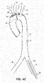
- FIGS. 1A and 1B illustrate a typical diseased aorta (2) with deposits (4) clinging to almost all interior surfaces.
- Patent document published US 2009/0182278 A1 discloses a system for deploying a device to a distal location across a diseased vessel, according to the preamble of claim 1.
- One embodiment is directed to a system for deploying a device to a distal location across a diseased vessel, comprising a railed expandable sheath defining a lumen therethrough and comprising two or more longitudinal rail structures coupled to a sheetlike member, the sheath having a collapsed configuration, wherein the sheath has a first cross sectional outer diameter and a first lumen inner diameter, and an expanded configuration, wherein the sheath has a second cross sectional outer diameter and a second lumen inner diameter; wherein in the collapsed configuration, the sheath is configured to be advanced across at least a portion of the diseased vessel to a position adjacent the distal location without substantial size interference between the first cross sectional outer diameter of the sheath and an inner diameter profile of a lumen of the diseased vessel; and wherein upon positioning the collapsed configuration to the desired position relative to the distal location, the sheath may be expanded to the expanded configuration with incremental pushing of a device longitudinally through the lumen such that loads imparted upon the sheath by
- the rail structures and sheetlike member may comprise the same material.
- the rail structures and sheetlike member may be co-formed.
- the rail structures may be coupled to an inside surface of the sheetlike member.
- the rail structures may be coupled to an outside surface of the sheetlike member.
- the rail structures may be at least partially encapsulated by the sheetlike member.
- the rail structures may be substantially longitudinally homogeneous in shape.
- the rail structures may be longitudinally inhomogeneous in shape.
- the two or more rail structures may be substantially homogeneous relative to each other. At least one of the two or more rail structures may be substantially inhomogeneous relative to at least one of the others.
- At least one of the two or more rail structures may comprise a cross sectional shape selected from the group consisting of: an elliptical shape; a rectangular shape; and a circular shape.
- the sheetlike structure may be substantially cylindrical when the sheath is in the expanded configuration.
- the sheetlike structure may be folded relative to the rail structures to form the collapsed configuration.
- the rail structures may be coupled to sheetlike structure in a manner in which they are exposed to the lumen.
- a longitudinal axis of at least one of the rail structures may be parallel to a longitudinal axis of the sheath.
- the at least one of the rail structures may have a configuration such that a longitudinal axis of said at least one rail structure is not parallel to a longitudinal axis of the sheath.
- the sheath may comprise two diametrically opposed rail structures coupled to the sheetlike member.
- the sheath may comprise three rail structures distributed circumferentially equidistantly.
- the sheath may comprise four rail structures distributed circumferentially equidistantly.
- the first lumen inner diameter may be equal to between about 0 mm and about 3 mm.
- the second lumen inner diameter may be equal to between about 6 mm and about 8 mm.
- the system may further comprise one or more radioopaque markers coupled to the sheath and configured to assist an operator observing fluoroscopy with positioning of the sheath relative to the diseased artery.
- the sheetlike member may comprise a material generally impermeable to blood.
- the sheetlike member may comprise one or more porous regions configured to allow blood to flow from a position within the lumen to a position across the sheetlike member and outside of the sheath.
- the one or more porous regions may comprise a porosity flow rate selected to support flow of blood into the carotid arteries.
- the porous regions may comprise one or more holes created across the sheetlike member. In one embodiment the holes may have a diameter of about 100 microns.
- the one or more porous regions may be configured to filter blood flowing through them to prevent passage of emboli that may be present within the lumen.
- the sheath may comprise one or more radioopaque markers located adjacent the one or more porous regions and being configured to allow an operator to visualize relative positioning of the one or more porous regions relative to one or more anatomical features using fluoroscopy.
- the rail structures may comprise a material selected from the group consisting of: polyethylene, ultra-high-molecular weight polyethylene, polyethylene terepthalate, polyoxymethylene, polytetrafluoroethylene, and co-polymers thereof.
- the rail structures may comprise nitinol alloy.
- the rail structures may be coated with a lubricious coating.
- the sheetlike member may comprise a material selected from the group consisting of: polyethylene, polytetrafluoroethylene, and co-polymers thereof.
- the system may further comprise a guidewire inserted through at least a portion of the lumen and configured to assist with guidance of the sheath through the diseased vessel.
- the system may further comprise a filtering device positioned within the diseased vessel in a configuration selected to prevent the passage of emboli to a tributary vessel of the diseased vessel.
- the system may further comprise a filtering device positioned within the diseased vessel at a location proximal to an access point wherein the sheath is inserted into the diseased vessel, the filtering device configured to prevent the passage of emboli to positions proximal of the location of the sheath.
- the system may further comprise a balloon dilation probe configured to complete the reconfiguration of the railed expandable sheath from the collapsed configuration to the expanded configuration.
- the railed expandable sheath may be self-expanding from the collapsed configuration to the expanded configuration.
- the system may further comprise a removable expansion retention member configured to retain the railed expandable sheath in the collapsed configuration.
- the expansion retention member may comprise a corset and tensile member assembly wherein the tensile member may be tensioned proximally to release the corset and allow expansion to the expanded configuration.
- One or more portions of the rail structures may comprise a ferromagnetic material.
- the system may further comprise a magnetic collapsing probe which may be passed through the lumen of the expanded configuration to assist with affirmative collapsing of the sheath back to the collapsed configuration.
- the system may further comprise a magnetic collapsing probe which may be positioned through the lumen of the expanded configuration to assist with maintaining the collapsed configuration until a reconfiguration to the expanded configuration is desired, at which point the probe may be withdrawn.
- the device may comprise an implantable prosthesis selected to be passed through the railed expandable sheath to the distal location across the diseased vessel.
- the implantable prosthesis may comprise a cardiac valve prosthesis.
- the railed expandable sheath may be configured to be twisted longitudinally to form the collapsed configuration, and untwisted longitudinally to form the expanded configuration.
- FIG. 1B an illustrative representation of a diseased aorta (2) is shown with deposits (4) distributed in several locations, including adjacent or within the left (6) and right (8) iliac arteries, and adjacent the junctions of the aortic arch with the left subclavian (10), left common carotid (12), and innominate artery (14). Navigating a diseased aorta (2) such as that depicted is indeed a challenge with conventional intravascular diagnostic and/or interventional hardware. For example, referring to Figures 2A-2F , a conventional instrument deployment is illustrated to demonstrate the disease-related challenges.
- the elongate instrument (46) is advanced in a retrograde direction through the aorta (2) distal tip (50) first.
- the instrument (46) may be a valve deployment member or probe, a catheter or conduit for conducting various interventions, etc.
- the distal end (50) may become a scraping interface (48) as it is urged past and against the tissue comprising the diseased aorta (2), and may accidentally and undesirably cause one or more pieces of the deposit material (4) to become loose and thereby flowing distally - perhaps into the brain or another undesirable deposit flow location.
- FIG. 2C shows that at the relatively extreme turning portions of the aortic arch, a conventional instrument may find itself located immediately adjacent or within the takeoff junctions of the joining arteries (10, 12, 14), where plaques and other deposits may be particularly mechanically vulnerable.
- Figures 2D-2F illustrate further advancement of the instrument (46) until the distal tip (50) is in the desired location for the planned diagnostic or interventional procedure.
- FIG. 3A a collapsed configuration (16) of a railed sheath is being inserted (80) distal tip (52) first.
- This collapsed configuration (16) may be inserted over a guidewire using conventional "over-the-wire" technique to assist in guiding the collapsed sheath configuration.
- the collapsed configuration (16) leaves much more room in the diseased aorta (2), thereby decreasing the likelihood of a scraping type mechanical interface relationship as described in reference to Figures 2A- 2F above.
- the railed sheath may comprise one or more pullwires to facilitate steering by an operator as the collapsed railed sheath (16) is advanced through the diseased aorta (2) using imaging modalities such as transcutaneous ultrasound and/or fluoroscopy to assist with the interactive steering of such configuration through the diseased vessel.
- the distal tip (52) of the collapsed configuration (16) has reached the desired interventional location (here the aortic outflow tract of the left ventricle cavity of the heart) in a minimally invasive way taking advantage of the relatively small cross sectional size of the collapsed configuration (16).
- the railed sheath indeed comprises a plurality of elongate rail structures (20; in the depicted embodiment 4 independent rail structures) coupled together by a sheet or sheetlike member (22) which, in the depicted collapsed configuration (16) is folded in between the elongate rail structures (20).
- a lumen (24) is defined through the railed sheath, and remains relatively small in diameter with the collapsed configuration (16).
- FIGS. 3E-3Q various configurations of railed sheath embodiments are illustrated in cross sectional views.
- One key core functionality of each of the illustrative embodiments described herein is the notion of protecting surrounding vascular and other anatomy by providing an intermediate surface between relatively large items to be moved through the vasculature (i.e., such as elongate tools, collapsed prostheses, etc) and the vasculature itself.
- the intermediate surface, or protective sheath generally comprises a sheetlike member that is reinforced by a plurality of generally longitudinal rail members that are configured to de-concentrate loads applied from the inside of the sheath toward the nearby vascular anatomy - in a manner somewhat akin to the manner in which point loads from train wheels on a railroad track are de- concentrated by the rails of the railroad track and absorbed over a large surface provided by the substrate underlying the railroad track.
- FIG. 3E an expanded form (26) of a railed sheath embodiment is shown having four elongate rail members distributed approximately equidistantly about the circumference of the expanded form (26).
- the expanded form has an approximately circular outer shape and defines an approximately circular inner lumen.
- FIG. 3F illustrates one configuration of the same hardware as shown in Figure 3E , but in the compressed or collapsed (16) format, with the sheetlike member (22) folded in both directions (i.e., partially folded onto each of the immediately adjacent rail structures 20).
- Figure 3G illustrates another configuration wherein the sheetlike member (22) is folded in one direction (i.e., to find mechanical support for slack portions on the next adjacent rail structure 20 in one direction as shown).
- Either of the collapsed configurations illustrated in Figures 3F and 3G may be suitable for deployment as in Figures 3A and 3B .
- Figures 3H-3M various expanded configuration (26) embodiments are depicted to illustrate that a great variety of combinations and permutations of hardware subcomponentry is within the scope of the invention.
- four elliptical rail structures (20) are coupled to the outer aspect of a substantially tubular sheetlike member (22), for example, with polymer welding, adhesive, suturing, or other coupling configuration.
- elongate rail structures of circular cross section (32) may be utilized for a more uniform bending modulus configuration
- elongate rail structures of rectangular or square cross section (34) may be utilized to present preferred bending axes to the overall structure of the railed sheath.
- FIG. 3K-3M embodiments similar to those illustrated in Figures 3H-3J are depicted, with exception that the embodiments of Figures 3K-3M have the elongate rail structures (20, 32, 34, respectively) more tightly integrated into the outer and inner shape of the overall structure (i.e., the outer aspects of the rail structures don't protrude out as much) .
- This may be accomplished, for example, by co-forming the rails (20, 32, 34, respectively) from the same bulk material as the sheetlike members (22), or at least partially encapsulating the rails (20, 32, 34, respectively) with the sheetlike member (22) material.
- various embodiments may be created to have a substantially smooth outer shape in the expanded state, and to have the elongate rail structures (20) protrude more into the inner lumen of the overall structure, which may be desired for mechanically guiding various portions of the diagnostic and/or interventional hardware that may be passed through the working lumen for the medical procedure.
- FIG. 3N one expanded configuration (26) is shown wherein a sheet like member (22) couples two elliptical rail structures (20) and two circular rail structures (32).
- a less cross sectionally homogeneous configuration is shown having two elliptical rail structures (20) coupled to the sheetlike member (22) diametrically across from each other, and a circular rail structure (32) diametrically opposed from a rectangular (34) rail structure at an angle so that the four depicted rail structures are not uniformly distributed about the circumference of the depicted cross section.
- three rectangular rail structures (34) are equidistantly circumferentially distributed about the cross section.
- a group of triangular (36), elliptical (20), and rectangular (34) rail structures is not equidistantly circumferentially distributed about the cross section.
- the various cross sectional permutations and combinations may be selected to improve deliverability, to have selected overall shape bending moduli, and to improve utility of the working lumen for passing through diagnostic and/or interventional tools during a medical procedure.
- the mechanical performance of the collapsible railed sheath may be customized and modified by changing the shapes, materials, and positions/orientations of various portions longitudinally (i.e., relative to the length of the overall catheter structure).
- a longitudinally uniform configuration has the same cross sectional configuration of rail structures (20) and sheetlike member (22) all along its length.
- Figure 3S an embodiment is shown wherein the outer shape of the overall structure does not change longitudinally, but wherein one or more of the rail structures (20) are tapered in shape (38) longitudinally, to provide greater overall bending modulus for the catheter at the end with the more tapered rail structures.
- FIG. 3T an embodiment is depicted which has not only one or more tapered (38) rail structures (20), but also a tapered (40) overall outer shape.
- the rail structures may be angularly oriented relative to the longitudinal axis of the overall shape.
- one or more of the rail structures (20) have a spiral orientation (42).
- Figure 3V shows that the same embodiment as shown in Figure 3U may be collapsed into a collapsed configuration (16), with the spiral orientation (42) of the one or more rail structures retained, but to a lesser spiraling angle relative to the longitudinal axis of the overall shape.
- the transition between collapsed configuration (16) and expanded configuration (26) may be accomplished by advancing a diagnostic and/or interventional instrument (44) through the lumen of the railed sheath.
- a diagnostic and/or interventional instrument (44) As shown in Figure 3W , the proximal portion of the railed sheath through which the instrument (44) has been advanced are in the expanded configuration (26), while the distal portion which has not yet been reached by the instrument (44) remains in the collapsed configuration (16) .
- the rails are specifically configured to assist in maintaining the orientation of the instrument (44) relative to the railed sheath and associated tubular anatomy as the instrument (44) is advanced through the railed sheath, to ensure that a predictable orientation is maintained when the instrument (44) reaches the desired diagnostic and/or interventional tissue theater.
- a percutaneous valve replacement procedure it is highly desirable to make sure that the valve prosthesis gets to the desired location, such as in the aortic outflow tract, in a predictable orientation relative to the structural tissue of the outflow tract, but also that damage is not caused to the patient during the deployment; the subject configurations are designed with such priorities in mind.
- the railed sheath may be a self-expanding sheath that is affirmatively retained in a collapsed configuration (16) until a desired time upon which it may be controllably converted to the expanded configuration (26).
- a corset-style collapse-retention member with a releasable (i.e., by proximal tension) tensile member may be utilized to retain the collapsed configuration, as in International PCT Publication No. WO 97/21403 , which is incorporated by reference herein in its entirety.
- an expanded configuration of a railed sheath (26) may comprise one or more porous regions (132) configured to be positioned adjacent tributary vessels to maintain flow through such vessels when the expanded railed sheath is in place.
- a porous region (132) is configured in this embodiment to ensure that flow coming into the distal tip (52) of the expanded railed sheath (26) is at least partially diverted up the associated tributary vessels (10, 12, 14) to supply with brain of the patient with blood during the procedure.
- the margins of the porous region may be marked with radioopaque markers to facilitate confirmation of placement of the porous region in a desired configuration relative to the anatomy, and transcutaneous and/or intravascular ultrasound and/or fluoroscopy with contrast agent may be utilized to confirm flow out of the aorta and into important tributary vessels during placement of the railed sheath.
- the porous region functions not only as a flow bypass, but also as a filter to capture any deposits or emboli that are being routed through the railed sheath; this may be accomplished by sizing the pores of the porous region to be large enough to pass blood plasma and red blood cells, but small enough to not pass typical emboli and deposits.
- the distal end of the railed sheath comprises a trumpet orfrustoconical shape (140) configured to maximize the likelihood that emboli or deposits that exit the adjacent anatomy (here the aortic outflow tract of the left ventricle cavity of the heart 138) by providing a more contoured fit of the adjacent anatomy.
- a trumpet orfrustoconical shape 140
- the flared distal frustoconical portion (140) may be retained in a compressed form by a movable or slideable cuff member (142), which, as shown in Figure 17C , may be retracted (144) proximally to allow the flared distal frustoconical portion (140) to be expandable or expanded (146) into the adjacent anatomy.
- an elongate insertion device (56) is shown inserting a diagnostic and/or interventional device (54), such as a collapsed aortic valve prosthesis, toward the desired anatomical location using the subject railed sheath.
- a diagnostic and/or interventional device such as a collapsed aortic valve prosthesis
- the elongate insertion device (56) may be safely retracted (58) back out through the expanded configuration (26) of the railed sheath.
- the railed sheath may be removed by pulling proximally (60) on the sheath and retracting it out, as shown in Figures 3-Z3 and 3-Z4 .
- the sheath may be forcibly converted from expanded configuration (26) to collapsed configuration (16) for removal, using, for example, an electromagnetic collapsing device. With all of the instrumentation removed, the access wound (for example, to one of the femoral arteries) may be closed and the procedure completed .
- a separate filtering device such as that sold under the tradename Embrella (RTM) by Edwards Lifesciences , Inc., may be utilized to assist in preventing unwanted particles or emboli from entering certain tributary vessels.
- a collapsed filtering device (68) may be advanced (62) with an elongate deployment member (66).
- the filtering device may be converted to an expanded configuration (70) wherein one or more wings (72, 74) form filtrating barriers across one or more tributary vessels (12, 14) and are temporarily retained in place by a retainer member (76).
- the deployment member (66) may be retracted (78), and as shown in Figure 4D , a collapsed railed sheath configuration (16) may be advanced (80).
- the collapsed railed sheath configuration (16) may be utilized as in reference to Figures 3A to 3Z-4 above, but with the temporary filter device in place.
- an elongate recapture device (56) may be inserted (62) to recapture the filtration device (64), as shown in Figures 4F and 4G , followed by retraction (58) and completion of the case.
- a tubular filter may be deployed before installation of a railed sheath to assist with filtering protection at one or more tributary vessel junctions.
- an elongate deployment member (88) removably coupled to a collapsed tubular filter (84) may be advanced (90) toward the anatomic location of interest, using, for example, fluoroscopic and/or ultrasound imaging guidance, which may be assisted by radioopaque markers on the filter (84) and/or deployment member (88), and/or the injection of imaging contrast agent.
- the tubular filter may be converted to the expanded configuration depicted in Figure 5C , using, for example, a balloon expansion element of the deployment member, or a release of a constraining member that retains a self-expanding configuration of the tubular filter until expansion is desired, after which the restraint is released and expansion ensues to the expanded configuration (86) of the tubular filter, which is configured to screen emboli and/or unwanted particles from entering the associated tributary vessels (10, 12, 14 in the depicted example).
- the deployment member (88) may be removed (92), as shown in Figure 5D , and a collapsed railed sheath configuration (16) may be inserted (80) through the expanded tubular filter (86), as shown in Figures 5E and 5F , to conduct a procedure in similar fashion as described above in reference to Figures 3A to 3-Z4 (in one embodiment the porosity of the porous portion (132) may be increased to maximize flow, since an additional filter is already in place; in another embodiment the porous portion (132) may simply comprise an open window section of the railed sheath).
- the railed sheath (26) may be removed (60), and as shown in Figure 5H , the filter deployment member (88) may be advanced to recapture the filter and pull it proximally out (92), causing it to slightly collapse and become mobile relative to the anatomy.
- two or more pullwires (94, 96) may be coupled to the tubular filter (either intraoperatively, or preoperatively and left in place during the procedure with leads to a proximal manual access point) and utilized to forcibly dislodge the tubular filter for withdrawal by causing radial collapse of at least a proximal portion (98) of the tubular filter (86) as it is pulled toward the small aperture of the deployment member (88) through which the pullwires or tether lines (94, 96) exit to couple to the filter.
- a distal portion of an electromagnetic deployment probe (100) may be configured to controllably attract ferromagnetic portions of the tubular filter to draw the filter back into a collapsed state when a voltage source (104) provides electromagnetic attraction toward one or more electromagnets coupled to the distal portion (102) of the electromagnetic deployment probe (100).
- a voltage source (104) provides electromagnetic attraction toward one or more electromagnets coupled to the distal portion (102) of the electromagnetic deployment probe (100).
- the tubular filter may be retracted and removed.
- a deployment probe (106) with a longer electromagnetic portion than that of Figure 5K may be utilized to assist in the affirmative re-collapsing of a railed sheath embodiment that comprises ferromagnetic portions which may be controllably attracted toward the electromagnetic deployment probe (106) using an operatively coupled voltage controller (108) .
- the voltage controller (108) may be configured to activate all of the electromagnets on the probe (106) simultaneously to re-collapse the associated length of the railed sheath simultaneously.
- the controller (108) may be configured to sequentially activate (and retain activation until release is desired) the various electromagnets comprising the probe to provide for a sequential longitudinal collapsing of the associated railed sheath (i.e., from the most proximal portion to the most distal portion, vice versa, etc).
- a deployment probe (106) similar to that depicted in Figure 6 may be utilized to forcibly retain a collapse configuration until sequential or simultaneous expansion of all portions of the railed sheath is desired.
- the magnet controller (108) may be configured to retain the collapsed state of the entire exposed length of the railed sheath during insertion.
- the magnet controller may be configured to either simultaneously or sequentially release portions of the railed sheath to allow for expansion to the expanded form (26) .
- Completion of expansion to the expanded form (26) may be completed as a result of a self-expanding infrastructure of the railed sheath, with the help of an expandable balloon, etc.
- a proximal filter may be placed proximal to the access point for the aforementioned hardware embodiments to prevent particles or emboli from flowing distally.
- a close up view of an access point (110, such as an arteriotomy) and associated vessels (6, 8) and deposits (4) is shown with a collapsed filtration device (112) being advanced (116) with a deployment member (114) through the access point (110).
- the deployment member (114) may be shaped such that the collapsed filtration device (112) can be tucked immediately proximal of the access point (110).
- the filtration device may be self-expanding or expandable (i.e., with a balloon) to be controllably converted into an expanded/deployed configuration (120) wherein blood flow (124) is directed across a filter mesh (112) portion of the expanded filter (120) to prevent passage of emboli, particles, and the like.
- the filter (120) has a tether member (126) which may be extended out of the access point (110) and used subsequently for recapture and removal of the filter.
- a collapsed railed sheath (16) may be advanced and utilized as in the embodiments described in reference to Figures 3A to 3Z-4 , with the further benefit of the distal protection filter in place.
- the railed sheath (26) may be retracted (60) past the still-deployed filter (120), as shown in Figure 8F , after which the tether member (126) may be utilized to assist in retraction (128) of the filter member out of the access point (110) and completion of the procedure.
- a railed sheath may be utilized to only partially protect a route to a targeted anatomical position for a diagnostic and/or interventional instrument.
- a railed sheath (26) may be deployed only across this length, and the instrumentation (56, 54) may be advanced across this length through the railed sheath (26), and then across the remainder of the length of the vessel to the targeted anatomy without the protection and/or mechanical guidance of the railed sheath.
- a guidewire and/or introducer sheath may be advanced across the access location to provide for guidance and support of additional instrumentation which may be advanced (306).
- a compressed configuration of a railed sheath may be advanced - for example, over-the-guidewire and through the introducer sheath - in a compressed configuration (308).
- the railed sheath may be expanded or allowed to expand to, for example, accommodate passage of an advancing interventional device (such as a percutaneous valve deployment assembly) across the railed sheath to the anatomical location of interest (312).
- an advancing interventional device such as a percutaneous valve deployment assembly
- the procedure may be conducted (314), after which the tools may be retracted (316), the railed sheath returned to a collapsed or partially collapsed configuration (for example, by simple proximal tensioning to partially collapse the railed sheath, by electromagnet-induced forced to fully collapse the railed sheath, etc) (318), and vascular access closed (320) to complete the procedure.
- the tools may be retracted (316)
- the railed sheath returned to a collapsed or partially collapsed configuration (for example, by simple proximal tensioning to partially collapse the railed sheath, by electromagnet-induced forced to fully collapse the railed sheath, etc) (318), and vascular access closed (320) to complete the procedure.
- a folding embolic filter may be advanced (322) and deployed (324) prior to introduction of the railed sheath (308); this filter may be reconfigured into a collapsed transport configuration (326) and retracted (328) before final closing of the vascular access (320).
- a tubular embolic filter may be advanced (330) and deployed (332) prior to introduction of the railed sheath (308); this filter may be reconfigured into a collapsed transport configuration (334) and retracted (336) before final closing of the vascular access (320).
- the railed sheath may be returned to a compressed configuration with the help of magnet- induced loads from a magnetic probe or portion of a probe (338) before retraction using the probe (340).
- FIG 14 an embodiment similar to that of Figure 10 is illustrated, with the exception that for railed sheath introduction, the collapsed configuration is actively maintained using magnetic loads (342), and expansion (344) to the expanded configuration after appropriate longitudinal advancement (310) is controllably facilitated by controllably decreasing or removing the magnetic loads, followed by retraction of the magnetic tool (346) and advancement of the interventional or diagnostic tools through the railed sheath (348).
- a proximal filter or "distal protection device” is installed (350) proximally; this filter may be removed (352) after ultimate removal of the railed sheath (318).
- distal protection device an embodiment similar to that of Figure 10 is illustrated, with the exception that the railed sheath may be only partially positioned across the length of the vascular route to the targeted anatomy (i.e., rather than protecting the entire length with a railed sheath, only a portion, such as a proximal portion, may be protected) (354).
- the rail structures may comprise various bio-compatible metals, such as titanium, alloys thereof such as Nitinol superalloy, and/or polymers such as polyethylene, ultra-high- molecular weight polyethylene, polyethylene terepthalate, polyoxymethylene, polytetrafluoroethylene, and co-polymers thereof.
- bio-compatible metals such as titanium, alloys thereof such as Nitinol superalloy
- polymers such as polyethylene, ultra-high- molecular weight polyethylene, polyethylene terepthalate, polyoxymethylene, polytetrafluoroethylene, and co-polymers thereof.
- the sheetlike member may comprise a material such as polyethylene, polytetrafluoroethylene, or co-polymers thereof.
- a vacuum device such as a syringe may be operatively coupled to the configuration (for example, coupled to or integrated into a proximal handle that forms a manual interface for inserting a railed sheath catheter), and may have an elongate distal portion that may be inserted into a deployed railed sheath catheter to vacuum away emboli that may be present.
- FIGS. 18A-18J various aspects of another embodiment of an intervention protection configuration are shown, wherein a distal portion of the delivery configuration is allowed to expand relative to a more proximal portion which may remain substantially more contracted or collapsed.
- a railed sheath in a collapsed configuration (16) has been inserted through a diseased vessel such as aorta (2), starting with transvascular access through a portion of the associated vasculature such as the left iliac artery (6), followed by insertion of the instrument assembly into a position as shown wherein the distal tip is located in a preferred location, such as adjacent an aortic valve of the patient.
- a proximal portion of the instrumentation, including a proximal control assembly (150) remains external to the vascular access for manipulation and control of the procedure, along with optional external drainage or exit of fluids or embolic or other materials which may collect within the instrumentation.
- the depicted embodiment comprises an atraumatic obturator tip (148) selected to reduce the results of impacts that such distal instrumentation may have during insertion and placement.
- the assembly may comprise a collapsed railed sheath portion (16) removably coupled to a distal obturator-jacket assembly (168) which has an atraumatic tip (148).
- the obturator-jacket assembly (168) preferably is coupled, through the lumen of the sheath and proximally out through a valved (154) port (156) defined through the tubular body assembly (164) of the proximal assembly (150), to an elongate obturator coupling member (152) which may be movably positioned through a central working lumen of the sheath (such as that referred to as element 24 above).
- the depicted proximal assembly (150) also comprises a second valved (158) port (160) which may be occupied by a portion of a sheath tip manipulation assembly, which may comprise a proximal manipulation structure or handle (162) which is coupled to a distal portion of the sheath using a movable tension-applying element such as a pullwire.
- a movable tension-applying element such as a pullwire.
- an operator may manually manipulate, or pull, the proximal manipulation structure (162) to tension the movable tension-applying element and cause closure of the distal tip of the sheath using a hoop configuration.
- the obturator-jacket assembly may be configured to assist in temporarily maintaining a collapsed configuration of a distal portion of the sheath, and may be configured to extend the full length of a particularly expandable portion of the sheath which may be expanded outward subsequent to removal of the obturator-jacket assembly (168) from its collapse restraint configuration as shown in Figure 18B .
- the obturator-jacket assembly (168) may be advanced or urged (166) distally relative to the remainder of the sheath assembly (16, 150), causing the obturator-jacket assembly (168), with its atraumatic distal tip (148), to become released from the remainder of the sheath assembly (16, 150) with such advancement.
- such distal advancement causes a thin jacket-like wrapper portion of the obturator-jacket assembly (168) to become torn or fractured along a predetermined pathway (i.e., via preexisting perforations created in the jacket-like wrapper portion) in a manner that substantially releases and decouples the underlying collapsed portions of the railed sheath assembly from the jacket-like wrapper portion (while the jacket-like wrapper portion remains firmly attached to the obturator tip 148), allowing a portion of the sheath to self-expand to an expanded configuration (26) as shown in Figure 18C and the close-up view of Figure 18D .
- the distal portion of the railed sheath may be allowed to become fully expanded (26), and then the obturator assembly (168, 152) may be pulled proximally (170) through the lumen of the sheath (24) and through the proximal assembly (150) where it may be removed.
- this embodiment of the railed sheath is in an expanded configuration wherein a proximal portion of the railed sheath remains in a relatively collapsed or small diameter configuration (16) as compared with the expanded distal portion (26), which features a plurality of structural rail members (32) configured to self-expand and support a tubular or frustoconical porous filter mesh (132) surface configured to capture particles that may enter it, such as clots or plaque particles.
- the expanded distal portion may be selected to have a length approximately equivalent to the arcuate length of the subject aortic arch.
- the embodiment depicted in close-up view in Figures 18G-18H features six elongate structural rail members (32) which may comprise a material such as a nickel titanium Nitinol superalloy; other embodiments may feature 4, 5, 7, 8, 9, 10, 11, 12, or more rail members (32), which may be configured to be prominent either to the inner surface or outer surface of the expanded portion (26), and may be configured to have various cross sectional areas and/or positions, as in the embodiments described above in reference to Figures 3E-3Q .
- six elongate structural rail members (32) which may comprise a material such as a nickel titanium Nitinol superalloy; other embodiments may feature 4, 5, 7, 8, 9, 10, 11, 12, or more rail members (32), which may be configured to be prominent either to the inner surface or outer surface of the expanded portion (26), and may be configured to have various cross sectional areas and/or positions, as in the embodiments described above in reference to Figures 3E-3Q .
- the most distal portion of the expanded sheath portion (26) may comprise a vessel engagement portion (172) selected to maximize physical accommodation of local endovascular geometry and/or terrain, so that particles moving through the pertinent vessel are biased to be captured by the railed sheath, not diverted around it.
- the depicted vessel engagement portion comprises a relatively low- modulus sheetlike material, which may comprise a thin biocompatible polymer, coupled in a cylindrical fashion to a relatively low-modulus zig-zag structure (176) intercoupled between two relatively low-modulus hoops (184, 186).
- These structures (176, 184, 186) may comprise relatively small-diameter Nitinol superalloy material, for example.
- a controllably collapsible hoop (174) may be intercoupled into the distal assembly and movably coupled to the proximal manipulation assembly (element 162 of Figure 18B , for example) to allow an operator to pull upon the proximal manipulation assembly and cause increased hoop tension in the controllably collapsible hoop (174), causing such hoop to controllably collapse and close the distal assembly into a closed-distal configuration (178), as shown in Figure 18I , after which the entire sheath assembly may be proximally (180) removed out of the subject anatomy while safely containing the contents of the sheath assembly which may have been captured during deployment, such as clots and/or plaque particles.
- the entire expanded portion (26), such as illustrated in Figure 18G is a self- expanding structure, in that it is biased to expand to the expanded configuration (26) upon release of mechanical constraint such as the aforementioned obturator jacket.
- only a tip portion is a self-expanding structure, such as a tip portion including the distal engagement portion (172) and a distal subportion of the frustoconical distal portion (140) of the sheath.
- the removable obturator jacket covering and restraining the underlying compressed distal portion of the sheath may be removed directly from the outside using a tensile member coupled to the outer surface of the jacket and configured to tear the jacket away from the underlying compressed distal portion of the sheath to allow such compressed distal portion to self-expand.
- the jacket covering may be pulled off from the outside using a tensile member, such as a pullwire configured to be manually and controllably tensioned from a proximal location using a handle or other tensioning fixture, coupled between the jacket and a proximal location accessible using the proximal assembly (150) and pulled proximally away from the sheath in a tear-away fashion prescribed by predetermined patterning (i.e., through perforated tear-away lines or patterns).
- a combination of release/removal from through the working lumen, and release/removal from the outside aspect of the sheath as described immediately above may be utilized to fully release the sheath distal end and allow self-expansion.
- the inventive protective configurations provide a means for conducting an intervention while also protecting the underlying tissue and related anatomy; further, the railed sheath configurations assist with delivery and alignment of tools and/or prostheses which may be related to the vascular intervention.
- vascular access may be established (304) and a guidewire and/or introducer may be advanced into the subject vessel lumen (306).
- a protective or railed sheath may be introduced (360) and advanced (310) in a compressed configuration to place the distal portion in a desired position relative to the subject anatomy (for example, in an aortic valve prosthesis deployment configuration, the sheath may be positioned to allow for deployment of the valve prosthesis adjacent the aortic outflow tract of the patient, as planned preoperatively).
- the protective or railed sheath may be converted to its expanded configuration, which may comprise advancement and then retraction of an obturator assembly, as described above in reference to Figures 18A-18J , which may remove a wrapper layer or compression layer coupled to the obturator, thereby allowing the underlying sheath portion to self-expand in a manner akin to that of a self-expanding stent prosthesis (362).
- intervention steps may be conducted which involve insertion and/or retraction of one or more devices, tools, or prostheses through the working lumen defined through the sheath, with protection provided to associated tissues by virtue of such sheath deployment (364).
- the tools may be removed (316), and the expanded distal portion of the sheath controllably returned to a safe removal configuration wherein at least a distal portion of the sheath is controllably collapsed or closed, such as by a hoop closure actuated by proximally pulling a tension or pullwire, as described above in reference to Figures 18A-18J (368).
- Vascular access may then be closed after removal of the sheath assembly (320).
- kits may further include instructions for use and be packaged in sterile trays or containers as commonly employed for such purposes.
- the invention includes methods that may be performed using the subject devices.
- the methods may comprise the act of providing such a suitable device. Such provision may be performed by the end user.
- the "providing" act merely requires the end user obtain, access, approach, position, set-up, activate, power-up or otherwise act to provide the requisite device in the subject method.
- Methods recited herein may be carried out in any order of the recited events which is logically possible, as well as in the recited order of events.
- lubricious coatings e.g., hydrophilic polymers such as polyvinylpyrrolidone-based compositions, fluoropolymers such as tetrafluoroethylene, hydrophilic gel or silicones
- hydrophilic polymers such as polyvinylpyrrolidone-based compositions
- fluoropolymers such as tetrafluoroethylene
- hydrophilic gel or silicones may be used in connection with various portions of the devices, such as relatively large interfacial surfaces of movably coupled parts, if desired, for example, to facilitate low friction manipulation or advancement of such objects relative to other portions of the instrumentation or nearby tissue structures.
- additional acts as commonly or logically employed.
- any optional feature of the inventive variations described may be set forth and claimed independently, or in combination with any one or more of the features described herein.
- Reference to a singular item includes the possibility that there are plural of the same items present. More specifically, as used herein and in claims associated hereto, the singular forms “a,” “an,” “said,” and “the” include plural referents unless the specifically stated otherwise.
- use of the articles allow for "at least one" of the subject item in the description above as well as claims associated with this disclosure.
- claims may be drafted to exclude any optional element. As such, this statement is intended to serve as antecedent basis for use of such exclusive terminology as “solely”, “only” and the like in connection with the recitation of claim elements, or use of a “negative” limitation.
Abstract
Description
- The present invention relates generally to medical interventions conducted through vessels such as the major arteries, and more particularly to access and deployment configurations for conducting percutaneous procedures such as percutaneous valve replacement.
- Gaining access to the heart is a continued challenge in cardiovascular medicine. Conventional procedures for accomplishing tasks such as valve replacement generally involve a thoracotomy and/or creation of one or more access ports across the wall of the heart itself, which is relatively highly invasive and therefore undesirable. Recent progress has been made in the area of percutaneous intervention, wherein instrumentation, such as catheters, guidewires, and prostheses, are brought to the heart through the vessels connected to the heart. One of the challenges with percutaneous approaches to procedures such as valve replacement, is that patients with diseased valves often have diseased major vessels, and the instrumentation required to accomplish a procedure such as a percutaneous valve replacement is often fairly large. For example, the un-expanded delivery size of a CoreValve (RTM) aortic valve prosthesis available from Medtronic, Inc. is approximately 18 French; the un-expanded delivery size of a Sapien (RTM) valve available from Edwards Lifesciences , Inc. is between 18 and 24 French, depending upon which size is utilized. Such outer sizes do not allow for a conventional guide catheter to be inserted as a protective layer between the tools and the tissue, and therefore the standard of care has become direct insertion of the valve instrumentation through the diseased vessels to reach the target location within or adjacent to the heart. Another complicating factor with such interventions is the fact that it is likely that the aorta through which the devices will be advanced will be diseased (one recent study concluded that 61% of patients over 65 years of age severe aortic valve stenosis also have severe aortic atherosclerosis; Osranek et al . , American Journal of Cardiology, 2009; 103: 713-717) .
Figures 1A and1B illustrate a typical diseased aorta (2) with deposits (4) clinging to almost all interior surfaces. This complicated surgical paradigm has lead some clinical researchers to believe that elevated stroke rates associated with such procedures may be related to the physical insertion of large interventional tools through diseased vessels and concomitant scaping or microscraping action of the tools against the diseased vessel walls, which is breaking portions of plaque loose and allowing these to flow with the bloodstream into the brain and other undesirable landing places. - Patent document published
US 2009/0182278 A1 discloses a system for deploying a device to a distal location across a diseased vessel, according to the preamble of claim 1. - There is a need for a configuration wherein a relatively thin but protective sheathlike member can be put in place to guide the interventional tools and prosthesis while mitigating load concentrations and/or scraping or abrasion of the interior of the subject vessels. The subject invention is directed to address such need.
- One embodiment is directed to a system for deploying a device to a distal location across a diseased vessel, comprising a railed expandable sheath defining a lumen therethrough and comprising two or more longitudinal rail structures coupled to a sheetlike member, the sheath having a collapsed configuration, wherein the sheath has a first cross sectional outer diameter and a first lumen inner diameter, and an expanded configuration, wherein the sheath has a second cross sectional outer diameter and a second lumen inner diameter; wherein in the collapsed configuration, the sheath is configured to be advanced across at least a portion of the diseased vessel to a position adjacent the distal location without substantial size interference between the first cross sectional outer diameter of the sheath and an inner diameter profile of a lumen of the diseased vessel; and wherein upon positioning the collapsed configuration to the desired position relative to the distal location, the sheath may be expanded to the expanded configuration with incremental pushing of a device longitudinally through the lumen such that loads imparted upon the sheath by the device are transferred to the rails and distributed to nearby portions of the diseased vessel in a deconcentrated and nonabrasive manner. The rail structures and sheetlike member may comprise the same material. The rail structures and sheetlike member may be co-formed. The rail structures may be coupled to an inside surface of the sheetlike member. The rail structures may be coupled to an outside surface of the sheetlike member. The rail structures may be at least partially encapsulated by the sheetlike member. The rail structures may be substantially longitudinally homogeneous in shape. The rail structures may be longitudinally inhomogeneous in shape. The two or more rail structures may be substantially homogeneous relative to each other. At least one of the two or more rail structures may be substantially inhomogeneous relative to at least one of the others. At least one of the two or more rail structures may comprise a cross sectional shape selected from the group consisting of: an elliptical shape; a rectangular shape; and a circular shape. The sheetlike structure may be substantially cylindrical when the sheath is in the expanded configuration. The sheetlike structure may be folded relative to the rail structures to form the collapsed configuration. The rail structures may be coupled to sheetlike structure in a manner in which they are exposed to the lumen. A longitudinal axis of at least one of the rail structures may be parallel to a longitudinal axis of the sheath. The at least one of the rail structures may have a configuration such that a longitudinal axis of said at least one rail structure is not parallel to a longitudinal axis of the sheath. The sheath may comprise two diametrically opposed rail structures coupled to the sheetlike member. The sheath may comprise three rail structures distributed circumferentially equidistantly. The sheath may comprise four rail structures distributed circumferentially equidistantly. The first lumen inner diameter may be equal to between about 0 mm and about 3 mm. The second lumen inner diameter may be equal to between about 6 mm and about 8 mm. The system may further comprise one or more radioopaque markers coupled to the sheath and configured to assist an operator observing fluoroscopy with positioning of the sheath relative to the diseased artery. The sheetlike member may comprise a material generally impermeable to blood. The sheetlike member may comprise one or more porous regions configured to allow blood to flow from a position within the lumen to a position across the sheetlike member and outside of the sheath. The one or more porous regions may comprise a porosity flow rate selected to support flow of blood into the carotid arteries. The porous regions may comprise one or more holes created across the sheetlike member. In one embodiment the holes may have a diameter of about 100 microns. The one or more porous regions may be configured to filter blood flowing through them to prevent passage of emboli that may be present within the lumen. The sheath may comprise one or more radioopaque markers located adjacent the one or more porous regions and being configured to allow an operator to visualize relative positioning of the one or more porous regions relative to one or more anatomical features using fluoroscopy. The rail structures may comprise a material selected from the group consisting of: polyethylene, ultra-high-molecular weight polyethylene, polyethylene terepthalate, polyoxymethylene, polytetrafluoroethylene, and co-polymers thereof. The rail structures may comprise nitinol alloy. The rail structures may be coated with a lubricious coating. The sheetlike member may comprise a material selected from the group consisting of: polyethylene, polytetrafluoroethylene, and co-polymers thereof. The system may further comprise a guidewire inserted through at least a portion of the lumen and configured to assist with guidance of the sheath through the diseased vessel. The system may further comprise a filtering device positioned within the diseased vessel in a configuration selected to prevent the passage of emboli to a tributary vessel of the diseased vessel. The system may further comprise a filtering device positioned within the diseased vessel at a location proximal to an access point wherein the sheath is inserted into the diseased vessel, the filtering device configured to prevent the passage of emboli to positions proximal of the location of the sheath. The system may further comprise a balloon dilation probe configured to complete the reconfiguration of the railed expandable sheath from the collapsed configuration to the expanded configuration. The railed expandable sheath may be self-expanding from the collapsed configuration to the expanded configuration. The system may further comprise a removable expansion retention member configured to retain the railed expandable sheath in the collapsed configuration. The expansion retention member may comprise a corset and tensile member assembly wherein the tensile member may be tensioned proximally to release the corset and allow expansion to the expanded configuration. One or more portions of the rail structures may comprise a ferromagnetic material. The system may further comprise a magnetic collapsing probe which may be passed through the lumen of the expanded configuration to assist with affirmative collapsing of the sheath back to the collapsed configuration. The system may further comprise a magnetic collapsing probe which may be positioned through the lumen of the expanded configuration to assist with maintaining the collapsed configuration until a reconfiguration to the expanded configuration is desired, at which point the probe may be withdrawn. The device may comprise an implantable prosthesis selected to be passed through the railed expandable sheath to the distal location across the diseased vessel. The implantable prosthesis may comprise a cardiac valve prosthesis. The railed expandable sheath may be configured to be twisted longitudinally to form the collapsed configuration, and untwisted longitudinally to form the expanded configuration.
-
-
Figures 1A - 1B illustrate various portions of a diseased aorta. -
Figures 2A - 2F illustrate aspects of a conventional interventional device deployment through a diseased aorta. -
Figures 3A - 3Z-4 illustrate various aspects of an inventive expandable railed sheath that may be used in conducting various cardiovascular procedures, such as a percutaneous aortic valve replacement procedure. -
Figures 4A - 4H illustrate aspects of a configuration similar to that ofFigures 3A - 3Z-4 , wherein a branch vessel protection filter is also incorporated. -
Figures 5A - 5K illustrate aspects of a configuration similar to that ofFigures 3A - 3Z-4 , wherein a tubular branch vessel protection filter is also incorporated. -
Figure 6 illustrates a configuration wherein a magnetic probe is utilized to collapse a sheath after an intervention has been conducted through an expanded form of the sheath. -
Figure 7 illustrates a configuration wherein a magnetic probe is utilized to retain a sheath in a collapsed form until an expansion to an expanded form is desired. -
Figures 8A - 8G illustrate aspects of a configuration similar to that ofFigures 3A - 3Z-4 , wherein a distal protection filter is also incorporated. -
Figure 9 illustrate aspects of a configuration similar to that ofFigures 3A - 3Z-4 , wherein only a proximal portion of the main vessel is protected by an embodiment of the inventive sheath. -
Figure 10 illustrates various aspects of a deployment technique in accordance with the present invention. -
Figure 11 illustrates various aspects of a deployment technique in accordance with the present invention. -
Figure 12 illustrates various aspects of a deployment technique in accordance with the present invention. -
Figure 13 illustrates various aspects of a deployment technique in accordance with the present invention. -
Figure 14 illustrates various aspects of a deployment technique in accordance with the present invention. -
Figure 15 illustrates various aspects of a deployment technique in accordance with the present invention. -
Figure 16 illustrates various aspects of a deployment technique in accordance with the present invention. -
Figures 17A-17C illustrate aspects of an embodiment of a railed sheath having a frustoconical distal portion configured to interface with a cardiovascular cavity. -
Figures 18A-18J illustrate various aspects of an inventive expandable railed sheath that may be used in conducting various cardiovascular procedures, such as a percutaneous aortic valve replacement procedure. -
Figure 19 illustrates various aspects of a deployment technique in accordance with the present invention. - Referring to
Figure 1B , an illustrative representation of a diseased aorta (2) is shown with deposits (4) distributed in several locations, including adjacent or within the left (6) and right (8) iliac arteries, and adjacent the junctions of the aortic arch with the left subclavian (10), left common carotid (12), and innominate artery (14). Navigating a diseased aorta (2) such as that depicted is indeed a challenge with conventional intravascular diagnostic and/or interventional hardware. For example, referring toFigures 2A-2F , a conventional instrument deployment is illustrated to demonstrate the disease-related challenges. Referring toFigure 2A , the elongate instrument (46) is advanced in a retrograde direction through the aorta (2) distal tip (50) first. The instrument (46) may be a valve deployment member or probe, a catheter or conduit for conducting various interventions, etc. Referring toFigure 2B , as the instrument (46) is advanced farther toward the targeted anatomy, the distal end (50) may become a scraping interface (48) as it is urged past and against the tissue comprising the diseased aorta (2), and may accidentally and undesirably cause one or more pieces of the deposit material (4) to become loose and thereby flowing distally - perhaps into the brain or another undesirable deposit flow location. Further, the scraping dynamic between the distal tip (50) of the instrument (46) and the aortic tissue may result in the formation of one or more embolic masses, which also may find themselves undesirably drifting with the flow path toward the brain or other tissue.Figure 2C shows that at the relatively extreme turning portions of the aortic arch, a conventional instrument may find itself located immediately adjacent or within the takeoff junctions of the joining arteries (10, 12, 14), where plaques and other deposits may be particularly mechanically vulnerable.Figures 2D-2F illustrate further advancement of the instrument (46) until the distal tip (50) is in the desired location for the planned diagnostic or interventional procedure. Subsequently, the instrumentation is typically retracted, causing yet another scraping interface type of interaction as the instrumentation is pulled proximally in a pathway opposite to that described in reference toFigures 2A- 2F , and additional risks for undesirable complication related to such interaction. - Referring to
Figures 3A - 3Z-4 , various aspects of deployment steps and configurations utilizing embodiments of the inventive expandable railed sheath are illustrated. Referring toFigure 3A , a collapsed configuration (16) of a railed sheath is being inserted (80) distal tip (52) first. This collapsed configuration (16) may be inserted over a guidewire using conventional "over-the-wire" technique to assist in guiding the collapsed sheath configuration. As compared with the insertion scenario of, for example,Figure 2A , the collapsed configuration (16) leaves much more room in the diseased aorta (2), thereby decreasing the likelihood of a scraping type mechanical interface relationship as described in reference toFigures 2A- 2F above. In one embodiment, the railed sheath may comprise one or more pullwires to facilitate steering by an operator as the collapsed railed sheath (16) is advanced through the diseased aorta (2) using imaging modalities such as transcutaneous ultrasound and/or fluoroscopy to assist with the interactive steering of such configuration through the diseased vessel. - Referring to
Figure 3B , the distal tip (52) of the collapsed configuration (16) has reached the desired interventional location (here the aortic outflow tract of the left ventricle cavity of the heart) in a minimally invasive way taking advantage of the relatively small cross sectional size of the collapsed configuration (16). Referring toFigures 3C and 3D , close up views of the collapsed configuration (16) are illustrated to show that the railed sheath indeed comprises a plurality of elongate rail structures (20; in the depictedembodiment 4 independent rail structures) coupled together by a sheet or sheetlike member (22) which, in the depicted collapsed configuration (16) is folded in between the elongate rail structures (20). A lumen (24) is defined through the railed sheath, and remains relatively small in diameter with the collapsed configuration (16). - Referring to
Figures 3E-3Q , various configurations of railed sheath embodiments are illustrated in cross sectional views. One key core functionality of each of the illustrative embodiments described herein is the notion of protecting surrounding vascular and other anatomy by providing an intermediate surface between relatively large items to be moved through the vasculature (i.e., such as elongate tools, collapsed prostheses, etc) and the vasculature itself. The intermediate surface, or protective sheath, generally comprises a sheetlike member that is reinforced by a plurality of generally longitudinal rail members that are configured to de-concentrate loads applied from the inside of the sheath toward the nearby vascular anatomy - in a manner somewhat akin to the manner in which point loads from train wheels on a railroad track are de- concentrated by the rails of the railroad track and absorbed over a large surface provided by the substrate underlying the railroad track. This load deconcentration is believed to provide protection of the underlying anatomy from focused loads that could dislodge plaques or other particles, or create emboli - either from the focused load interface itself, or from any scraping or abrading interfacing that may be related to conventionally pushing a piece of hardware past the unprotected anatomy, as inFigures 2A-2F . Referring toFigure 3E , an expanded form (26) of a railed sheath embodiment is shown having four elongate rail members distributed approximately equidistantly about the circumference of the expanded form (26). The expanded form has an approximately circular outer shape and defines an approximately circular inner lumen. The elongate rail structures themselves have elliptical cross sectional shape profiles (20) configured to atraumatically and easily accommodate sliding of another diagnostic or interventional device through the lumen during a medical procedure such as a percutaneous valve replacement.Figure 3F illustrates one configuration of the same hardware as shown inFigure 3E , but in the compressed or collapsed (16) format, with the sheetlike member (22) folded in both directions (i.e., partially folded onto each of the immediately adjacent rail structures 20). -
Figure 3G illustrates another configuration wherein the sheetlike member (22) is folded in one direction (i.e., to find mechanical support for slack portions on the nextadjacent rail structure 20 in one direction as shown). Either of the collapsed configurations illustrated inFigures 3F and 3G , for example, may be suitable for deployment as inFigures 3A and3B . Referring toFigures 3H-3M , various expanded configuration (26) embodiments are depicted to illustrate that a great variety of combinations and permutations of hardware subcomponentry is within the scope of the invention. Referring toFigure 3H , four elliptical rail structures (20) are coupled to the outer aspect of a substantially tubular sheetlike member (22), for example, with polymer welding, adhesive, suturing, or other coupling configuration. The outer aspects of such configuration may be coated with a lubricious polymer to assist in the ease of sliding such a configuration past nearby tissue structures in a collapsed state; similarly, the inner aspects may be coated with a lubricous coating or surface to assist with slidable engagement between the expanded state of the railed sheath and instruments which may be passed through the working lumen during diagnostic and/or interventional procedure steps. Referring toFigure 3I , in one embodiment, elongate rail structures of circular cross section (32) may be utilized for a more uniform bending modulus configuration, and referring toFigure 3J , elongate rail structures of rectangular or square cross section (34) may be utilized to present preferred bending axes to the overall structure of the railed sheath. Referring toFigures 3K-3M , embodiments similar to those illustrated inFigures 3H-3J are depicted, with exception that the embodiments ofFigures 3K-3M have the elongate rail structures (20, 32, 34, respectively) more tightly integrated into the outer and inner shape of the overall structure (i.e., the outer aspects of the rail structures don't protrude out as much) . This may be accomplished, for example, by co-forming the rails (20, 32, 34, respectively) from the same bulk material as the sheetlike members (22), or at least partially encapsulating the rails (20, 32, 34, respectively) with the sheetlike member (22) material. Referring back to the embodiment ofFigure 3E , various embodiments may be created to have a substantially smooth outer shape in the expanded state, and to have the elongate rail structures (20) protrude more into the inner lumen of the overall structure, which may be desired for mechanically guiding various portions of the diagnostic and/or interventional hardware that may be passed through the working lumen for the medical procedure. - Referring to
Figures 3N-3Q , various configurations are shown to illustrate that cross sectional homogeneity is not only not necessary, but may not be preferred in some scenarios. - Referring to
Figure 3N , one expanded configuration (26) is shown wherein a sheet like member (22) couples two elliptical rail structures (20) and two circular rail structures (32). - Referring to
Figure 3O , a less cross sectionally homogeneous configuration is shown having two elliptical rail structures (20) coupled to the sheetlike member (22) diametrically across from each other, and a circular rail structure (32) diametrically opposed from a rectangular (34) rail structure at an angle so that the four depicted rail structures are not uniformly distributed about the circumference of the depicted cross section. Referring toFigure 3P , three rectangular rail structures (34) are equidistantly circumferentially distributed about the cross section. Referring toFigure 3Q , a group of triangular (36), elliptical (20), and rectangular (34) rail structures is not equidistantly circumferentially distributed about the cross section. The various cross sectional permutations and combinations may be selected to improve deliverability, to have selected overall shape bending moduli, and to improve utility of the working lumen for passing through diagnostic and/or interventional tools during a medical procedure. - Further, the mechanical performance of the collapsible railed sheath may be customized and modified by changing the shapes, materials, and positions/orientations of various portions longitudinally (i.e., relative to the length of the overall catheter structure). Several such configurations are illustrated in
Figures 3R-3V . Referring toFigure 3R , a longitudinally uniform configuration has the same cross sectional configuration of rail structures (20) and sheetlike member (22) all along its length. Referring toFigure 3S , an embodiment is shown wherein the outer shape of the overall structure does not change longitudinally, but wherein one or more of the rail structures (20) are tapered in shape (38) longitudinally, to provide greater overall bending modulus for the catheter at the end with the more tapered rail structures. Referring toFigure 3T , an embodiment is depicted which has not only one or more tapered (38) rail structures (20), but also a tapered (40) overall outer shape. Such a configuration would have inner lumen size limitations, but would provide greater overall bending modulus for the catheter at the end with the more tapered rail structures and overall shape. Referring toFigures 3U and 3V , the rail structures may be angularly oriented relative to the longitudinal axis of the overall shape. As shown in the expanded configuration (26) ofFigure 3U , one or more of the rail structures (20) have a spiral orientation (42).Figure 3V shows that the same embodiment as shown inFigure 3U may be collapsed into a collapsed configuration (16), with the spiral orientation (42) of the one or more rail structures retained, but to a lesser spiraling angle relative to the longitudinal axis of the overall shape. - Referring to
Figures 3W and 3X , the transition between collapsed configuration (16) and expanded configuration (26) may be accomplished by advancing a diagnostic and/or interventional instrument (44) through the lumen of the railed sheath. As shown inFigure 3W , the proximal portion of the railed sheath through which the instrument (44) has been advanced are in the expanded configuration (26), while the distal portion which has not yet been reached by the instrument (44) remains in the collapsed configuration (16) . In one embodiment, the rails are specifically configured to assist in maintaining the orientation of the instrument (44) relative to the railed sheath and associated tubular anatomy as the instrument (44) is advanced through the railed sheath, to ensure that a predictable orientation is maintained when the instrument (44) reaches the desired diagnostic and/or interventional tissue theater. For example, in the case of a percutaneous valve replacement procedure, it is highly desirable to make sure that the valve prosthesis gets to the desired location, such as in the aortic outflow tract, in a predictable orientation relative to the structural tissue of the outflow tract, but also that damage is not caused to the patient during the deployment; the subject configurations are designed with such priorities in mind. In another embodiment, as described in further detail below, the railed sheath may be a self-expanding sheath that is affirmatively retained in a collapsed configuration (16) until a desired time upon which it may be controllably converted to the expanded configuration (26). A corset-style collapse-retention member with a releasable (i.e., by proximal tension) tensile member may be utilized to retain the collapsed configuration, as in InternationalPCT Publication No. WO 97/21403 - Referring to
Figure 3Y , in one embodiment, an expanded configuration of a railed sheath (26) may comprise one or more porous regions (132) configured to be positioned adjacent tributary vessels to maintain flow through such vessels when the expanded railed sheath is in place. As shown inFigure 3Y , a porous region (132) is configured in this embodiment to ensure that flow coming into the distal tip (52) of the expanded railed sheath (26) is at least partially diverted up the associated tributary vessels (10, 12, 14) to supply with brain of the patient with blood during the procedure. The margins of the porous region may be marked with radioopaque markers to facilitate confirmation of placement of the porous region in a desired configuration relative to the anatomy, and transcutaneous and/or intravascular ultrasound and/or fluoroscopy with contrast agent may be utilized to confirm flow out of the aorta and into important tributary vessels during placement of the railed sheath. Preferably the porous region functions not only as a flow bypass, but also as a filter to capture any deposits or emboli that are being routed through the railed sheath; this may be accomplished by sizing the pores of the porous region to be large enough to pass blood plasma and red blood cells, but small enough to not pass typical emboli and deposits. Referring ahead toFigures 17A-17C , an embodiment similar to that ofFigure 3Y is depicted, but in this case the distal end of the railed sheath comprises a trumpet orfrustoconical shape (140) configured to maximize the likelihood that emboli or deposits that exit the adjacent anatomy (here the aortic outflow tract of the left ventricle cavity of the heart 138) by providing a more contoured fit of the adjacent anatomy. Referring toFigure 17B , during deployment, the flared distal frustoconical portion (140) may be retained in a compressed form by a movable or slideable cuff member (142), which, as shown inFigure 17C , may be retracted (144) proximally to allow the flared distal frustoconical portion (140) to be expandable or expanded (146) into the adjacent anatomy. - In both
Figure 17A and3Y , an elongate insertion device (56) is shown inserting a diagnostic and/or interventional device (54), such as a collapsed aortic valve prosthesis, toward the desired anatomical location using the subject railed sheath. Referring toFigures 3Z , and3-Z1 with the device (56) safely deployed into the subject anatomy, the elongate insertion device (56) may be safely retracted (58) back out through the expanded configuration (26) of the railed sheath. Referring toFigure 3-Z2 , with the diagnostic and/or interventional procedure substantially completed, the railed sheath may be removed by pulling proximally (60) on the sheath and retracting it out, as shown inFigures 3-Z3 and3-Z4 . In another embodiment, as described in further detail below, the sheath may be forcibly converted from expanded configuration (26) to collapsed configuration (16) for removal, using, for example, an electromagnetic collapsing device. With all of the instrumentation removed, the access wound (for example, to one of the femoral arteries) may be closed and the procedure completed . - Referring to
Figures 4A-4H , in one embodiment a separate filtering device, such as that sold under the tradename Embrella (RTM) by Edwards Lifesciences , Inc., may be utilized to assist in preventing unwanted particles or emboli from entering certain tributary vessels. Referring toFigure 4A , a collapsed filtering device (68) may be advanced (62) with an elongate deployment member (66). Referring toFigure 4B , the filtering device may be converted to an expanded configuration (70) wherein one or more wings (72, 74) form filtrating barriers across one or more tributary vessels (12, 14) and are temporarily retained in place by a retainer member (76). - Referring to
Figure 4C , the deployment member (66) may be retracted (78), and as shown inFigure 4D , a collapsed railed sheath configuration (16) may be advanced (80). Referring toFigure 4E , the collapsed railed sheath configuration (16) may be utilized as in reference toFigures 3A to 3Z-4 above, but with the temporary filter device in place. After the railed sheath has been utilized for a diagnostic and/or interventional procedure, it may be removed, and an elongate recapture device (56) may be inserted (62) to recapture the filtration device (64), as shown inFigures 4F and4G , followed by retraction (58) and completion of the case. - Referring to
Figures 5A-5K , in another embodiment, a tubular filter may be deployed before installation of a railed sheath to assist with filtering protection at one or more tributary vessel junctions. Referring toFigure 5A , an elongate deployment member (88) removably coupled to a collapsed tubular filter (84) may be advanced (90) toward the anatomic location of interest, using, for example, fluoroscopic and/or ultrasound imaging guidance, which may be assisted by radioopaque markers on the filter (84) and/or deployment member (88), and/or the injection of imaging contrast agent. Referring toFigure 5B , with the collapsed tubular filter (84) in the desired longitudinal position, the tubular filter may be converted to the expanded configuration depicted inFigure 5C , using, for example, a balloon expansion element of the deployment member, or a release of a constraining member that retains a self-expanding configuration of the tubular filter until expansion is desired, after which the restraint is released and expansion ensues to the expanded configuration (86) of the tubular filter, which is configured to screen emboli and/or unwanted particles from entering the associated tributary vessels (10, 12, 14 in the depicted example). The deployment member (88) may be removed (92), as shown inFigure 5D , and a collapsed railed sheath configuration (16) may be inserted (80) through the expanded tubular filter (86), as shown inFigures 5E and5F , to conduct a procedure in similar fashion as described above in reference toFigures 3A to 3-Z4 (in one embodiment the porosity of the porous portion (132) may be increased to maximize flow, since an additional filter is already in place; in another embodiment the porous portion (132) may simply comprise an open window section of the railed sheath). Referring toFigure 5G , with the procedure coming to completion, the railed sheath (26) may be removed (60), and as shown inFigure 5H , the filter deployment member (88) may be advanced to recapture the filter and pull it proximally out (92), causing it to slightly collapse and become mobile relative to the anatomy. Referring toFigure 5I , in another embodiment, two or more pullwires (94, 96) may be coupled to the tubular filter (either intraoperatively, or preoperatively and left in place during the procedure with leads to a proximal manual access point) and utilized to forcibly dislodge the tubular filter for withdrawal by causing radial collapse of at least a proximal portion (98) of the tubular filter (86) as it is pulled toward the small aperture of the deployment member (88) through which the pullwires or tether lines (94, 96) exit to couple to the filter. Referring toFigure 5J , in another embodiment, a distal portion of an electromagnetic deployment probe (100) may be configured to controllably attract ferromagnetic portions of the tubular filter to draw the filter back into a collapsed state when a voltage source (104) provides electromagnetic attraction toward one or more electromagnets coupled to the distal portion (102) of the electromagnetic deployment probe (100). Referring toFigure 5K , the tubular filter may be retracted and removed. - Referring to
Figure 6 , a deployment probe (106) with a longer electromagnetic portion than that ofFigure 5K may be utilized to assist in the affirmative re-collapsing of a railed sheath embodiment that comprises ferromagnetic portions which may be controllably attracted toward the electromagnetic deployment probe (106) using an operatively coupled voltage controller (108) . In one embodiment, the voltage controller (108) may be configured to activate all of the electromagnets on the probe (106) simultaneously to re-collapse the associated length of the railed sheath simultaneously. In another embodiment, the controller (108) may be configured to sequentially activate (and retain activation until release is desired) the various electromagnets comprising the probe to provide for a sequential longitudinal collapsing of the associated railed sheath (i.e., from the most proximal portion to the most distal portion, vice versa, etc). - Referring to
Figure 7 , a deployment probe (106) similar to that depicted inFigure 6 may be utilized to forcibly retain a collapse configuration until sequential or simultaneous expansion of all portions of the railed sheath is desired. In other words, the magnet controller (108) may be configured to retain the collapsed state of the entire exposed length of the railed sheath during insertion. When the desired longitudinal positioning has been accomplished, the magnet controller may be configured to either simultaneously or sequentially release portions of the railed sheath to allow for expansion to the expanded form (26) . Completion of expansion to the expanded form (26) may be completed as a result of a self-expanding infrastructure of the railed sheath, with the help of an expandable balloon, etc. - Referring to
Figures 8A - 8G , a proximal filter, or "distal protection device", may be placed proximal to the access point for the aforementioned hardware embodiments to prevent particles or emboli from flowing distally. Referring toFigure 8A , a close up view of an access point (110, such as an arteriotomy) and associated vessels (6, 8) and deposits (4) is shown with a collapsed filtration device (112) being advanced (116) with a deployment member (114) through the access point (110). - Referring to
Figure 8B , the deployment member (114) may be shaped such that the collapsed filtration device (112) can be tucked immediately proximal of the access point (110). As shown inFigure 8C , the filtration device may be self-expanding or expandable (i.e., with a balloon) to be controllably converted into an expanded/deployed configuration (120) wherein blood flow (124) is directed across a filter mesh (112) portion of the expanded filter (120) to prevent passage of emboli, particles, and the like. Preferably the filter (120) has a tether member (126) which may be extended out of the access point (110) and used subsequently for recapture and removal of the filter. - Referring to
Figures 8D and8E , with the expanded filter (120) in place a collapsed railed sheath (16) may be advanced and utilized as in the embodiments described in reference toFigures 3A to 3Z-4 , with the further benefit of the distal protection filter in place. With the procedure coming to a close, the railed sheath (26) may be retracted (60) past the still-deployed filter (120), as shown inFigure 8F , after which the tether member (126) may be utilized to assist in retraction (128) of the filter member out of the access point (110) and completion of the procedure. - Referring to
Figure 9 , a railed sheath may be utilized to only partially protect a route to a targeted anatomical position for a diagnostic and/or interventional instrument. For example, if the main objective is to protect the subject vessel pathway between the lower ascending aorta (130) and the access point, a railed sheath (26) may be deployed only across this length, and the instrumentation (56, 54) may be advanced across this length through the railed sheath (26), and then across the remainder of the length of the vessel to the targeted anatomy without the protection and/or mechanical guidance of the railed sheath. - Referring to
Figure 10 , a deployment technique is illustrated wherein subsequent to preoperative analysis (302) and establishment of vascular access (304), a guidewire and/or introducer sheath may be advanced across the access location to provide for guidance and support of additional instrumentation which may be advanced (306). A compressed configuration of a railed sheath may be advanced - for example, over-the-guidewire and through the introducer sheath - in a compressed configuration (308). Once the railed sheath has reached a desired longitudinal position (310) for the interventional and/or diagnostic procedure, the railed sheath may be expanded or allowed to expand to, for example, accommodate passage of an advancing interventional device (such as a percutaneous valve deployment assembly) across the railed sheath to the anatomical location of interest (312). With the expanded configuration of the railed sheath remaining in situ, the procedure may be conducted (314), after which the tools may be retracted (316), the railed sheath returned to a collapsed or partially collapsed configuration (for example, by simple proximal tensioning to partially collapse the railed sheath, by electromagnet-induced forced to fully collapse the railed sheath, etc) (318), and vascular access closed (320) to complete the procedure. - Referring to
Figure 11 , an embodiment similar to that ofFigure 10 is illustrated, with the exception that a folding embolic filter may be advanced (322) and deployed (324) prior to introduction of the railed sheath (308); this filter may be reconfigured into a collapsed transport configuration (326) and retracted (328) before final closing of the vascular access (320). - Referring to
Figure 12 , an embodiment similar to that ofFigure 10 is illustrated, with the exception that a tubular embolic filter may be advanced (330) and deployed (332) prior to introduction of the railed sheath (308); this filter may be reconfigured into a collapsed transport configuration (334) and retracted (336) before final closing of the vascular access (320). - Referring to
Figure 13 , an embodiment similar to that ofFigure 10 is illustrated, with the exception that after removal of the interventional tools (316), the railed sheath may be returned to a compressed configuration with the help of magnet- induced loads from a magnetic probe or portion of a probe (338) before retraction using the probe (340). - Referring to
Figure 14 , an embodiment similar to that ofFigure 10 is illustrated, with the exception that for railed sheath introduction, the collapsed configuration is actively maintained using magnetic loads (342), and expansion (344) to the expanded configuration after appropriate longitudinal advancement (310) is controllably facilitated by controllably decreasing or removing the magnetic loads, followed by retraction of the magnetic tool (346) and advancement of the interventional or diagnostic tools through the railed sheath (348). - Referring to
Figure 15 , an embodiment similar to that ofFigure 10 is illustrated, with the exception that after vascular access is established (304), a proximal filter, or "distal protection device" is installed (350) proximally; this filter may be removed (352) after ultimate removal of the railed sheath (318). Referring toFigure 16 , an embodiment similar to that ofFigure 10 is illustrated, with the exception that the railed sheath may be only partially positioned across the length of the vascular route to the targeted anatomy (i.e., rather than protecting the entire length with a railed sheath, only a portion, such as a proximal portion, may be protected) (354). The rail structures may comprise various bio-compatible metals, such as titanium, alloys thereof such as Nitinol superalloy, and/or polymers such as polyethylene, ultra-high- molecular weight polyethylene, polyethylene terepthalate, polyoxymethylene, polytetrafluoroethylene, and co-polymers thereof. - The sheetlike member may comprise a material such as polyethylene, polytetrafluoroethylene, or co-polymers thereof.
- In one embodiment, a vacuum device such as a syringe may be operatively coupled to the configuration (for example, coupled to or integrated into a proximal handle that forms a manual interface for inserting a railed sheath catheter), and may have an elongate distal portion that may be inserted into a deployed railed sheath catheter to vacuum away emboli that may be present.
- Referring to
Figures 18A-18J , various aspects of another embodiment of an intervention protection configuration are shown, wherein a distal portion of the delivery configuration is allowed to expand relative to a more proximal portion which may remain substantially more contracted or collapsed. Referring toFigure 18A , a railed sheath in a collapsed configuration (16) has been inserted through a diseased vessel such as aorta (2), starting with transvascular access through a portion of the associated vasculature such as the left iliac artery (6), followed by insertion of the instrument assembly into a position as shown wherein the distal tip is located in a preferred location, such as adjacent an aortic valve of the patient. A proximal portion of the instrumentation, including a proximal control assembly (150) remains external to the vascular access for manipulation and control of the procedure, along with optional external drainage or exit of fluids or embolic or other materials which may collect within the instrumentation. The depicted embodiment comprises an atraumatic obturator tip (148) selected to reduce the results of impacts that such distal instrumentation may have during insertion and placement. - Referring to
Figure 18B , without the associated anatomy (i.e., from the illustration ofFigure 18A ), the assembly may comprise a collapsed railed sheath portion (16) removably coupled to a distal obturator-jacket assembly (168) which has an atraumatic tip (148). The obturator-jacket assembly (168) preferably is coupled, through the lumen of the sheath and proximally out through a valved (154) port (156) defined through the tubular body assembly (164) of the proximal assembly (150), to an elongate obturator coupling member (152) which may be movably positioned through a central working lumen of the sheath (such as that referred to aselement 24 above). The depicted proximal assembly (150) also comprises a second valved (158) port (160) which may be occupied by a portion of a sheath tip manipulation assembly, which may comprise a proximal manipulation structure or handle (162) which is coupled to a distal portion of the sheath using a movable tension-applying element such as a pullwire. In one embodiment, as described below, an operator may manually manipulate, or pull, the proximal manipulation structure (162) to tension the movable tension-applying element and cause closure of the distal tip of the sheath using a hoop configuration. The obturator-jacket assembly may be configured to assist in temporarily maintaining a collapsed configuration of a distal portion of the sheath, and may be configured to extend the full length of a particularly expandable portion of the sheath which may be expanded outward subsequent to removal of the obturator-jacket assembly (168) from its collapse restraint configuration as shown inFigure 18B . For example, referring toFigure 18C , with the sheath in a desired position relative to the associated anatomy, the obturator-jacket assembly (168) may be advanced or urged (166) distally relative to the remainder of the sheath assembly (16, 150), causing the obturator-jacket assembly (168), with its atraumatic distal tip (148), to become released from the remainder of the sheath assembly (16, 150) with such advancement. In one embodiment, such distal advancement causes a thin jacket-like wrapper portion of the obturator-jacket assembly (168) to become torn or fractured along a predetermined pathway (i.e., via preexisting perforations created in the jacket-like wrapper portion) in a manner that substantially releases and decouples the underlying collapsed portions of the railed sheath assembly from the jacket-like wrapper portion (while the jacket-like wrapper portion remains firmly attached to the obturator tip 148), allowing a portion of the sheath to self-expand to an expanded configuration (26) as shown inFigure 18C and the close-up view ofFigure 18D . Referring toFigure 18E , with full distal advancement of the obturator assembly (168, 152), the distal portion of the railed sheath may be allowed to become fully expanded (26), and then the obturator assembly (168, 152) may be pulled proximally (170) through the lumen of the sheath (24) and through the proximal assembly (150) where it may be removed. - Referring to
Figures 18F-18H , with the obturator assembly removed, this embodiment of the railed sheath is in an expanded configuration wherein a proximal portion of the railed sheath remains in a relatively collapsed or small diameter configuration (16) as compared with the expanded distal portion (26), which features a plurality of structural rail members (32) configured to self-expand and support a tubular or frustoconical porous filter mesh (132) surface configured to capture particles that may enter it, such as clots or plaque particles. In one embodiment wherein the sheath assembly is configured for aortic deployment, the expanded distal portion may be selected to have a length approximately equivalent to the arcuate length of the subject aortic arch. The embodiment depicted in close-up view inFigures 18G-18H features six elongate structural rail members (32) which may comprise a material such as a nickel titanium Nitinol superalloy; other embodiments may feature 4, 5, 7, 8, 9, 10, 11, 12, or more rail members (32), which may be configured to be prominent either to the inner surface or outer surface of the expanded portion (26), and may be configured to have various cross sectional areas and/or positions, as in the embodiments described above in reference toFigures 3E-3Q . - Referring to
Figure 18G , in one embodiment the most distal portion of the expanded sheath portion (26) may comprise a vessel engagement portion (172) selected to maximize physical accommodation of local endovascular geometry and/or terrain, so that particles moving through the pertinent vessel are biased to be captured by the railed sheath, not diverted around it. The depicted vessel engagement portion comprises a relatively low- modulus sheetlike material, which may comprise a thin biocompatible polymer, coupled in a cylindrical fashion to a relatively low-modulus zig-zag structure (176) intercoupled between two relatively low-modulus hoops (184, 186). These structures (176, 184, 186) may comprise relatively small-diameter Nitinol superalloy material, for example. A controllably collapsible hoop (174) may be intercoupled into the distal assembly and movably coupled to the proximal manipulation assembly (element 162 ofFigure 18B , for example) to allow an operator to pull upon the proximal manipulation assembly and cause increased hoop tension in the controllably collapsible hoop (174), causing such hoop to controllably collapse and close the distal assembly into a closed-distal configuration (178), as shown inFigure 18I , after which the entire sheath assembly may be proximally (180) removed out of the subject anatomy while safely containing the contents of the sheath assembly which may have been captured during deployment, such as clots and/or plaque particles. In one embodiment, the entire expanded portion (26), such as illustrated inFigure 18G , is a self- expanding structure, in that it is biased to expand to the expanded configuration (26) upon release of mechanical constraint such as the aforementioned obturator jacket. In another embodiment, only a tip portion is a self-expanding structure, such as a tip portion including the distal engagement portion (172) and a distal subportion of the frustoconical distal portion (140) of the sheath. - In another embodiment, the removable obturator jacket covering and restraining the underlying compressed distal portion of the sheath, such as in the assembly of
Figure 18B , may be removed directly from the outside using a tensile member coupled to the outer surface of the jacket and configured to tear the jacket away from the underlying compressed distal portion of the sheath to allow such compressed distal portion to self-expand. In other words, rather than inserting, then retracting the obturator member to detach and remove the jacket covering from the underlying compressed distal portion of the sheath by pulling the removed jacket out through the working lumen of the sheath, the jacket covering may be pulled off from the outside using a tensile member, such as a pullwire configured to be manually and controllably tensioned from a proximal location using a handle or other tensioning fixture, coupled between the jacket and a proximal location accessible using the proximal assembly (150) and pulled proximally away from the sheath in a tear-away fashion prescribed by predetermined patterning (i.e., through perforated tear-away lines or patterns). In another embodiment, a combination of release/removal from through the working lumen, and release/removal from the outside aspect of the sheath as described immediately above, may be utilized to fully release the sheath distal end and allow self-expansion. - In summary, as described above, the inventive protective configurations provide a means for conducting an intervention while also protecting the underlying tissue and related anatomy; further, the railed sheath configurations assist with delivery and alignment of tools and/or prostheses which may be related to the vascular intervention.
- Referring to the process flow embodiment of
Figure 19 , for example, after preoperative analysis (302), vascular access may be established (304) and a guidewire and/or introducer may be advanced into the subject vessel lumen (306). A protective or railed sheath may be introduced (360) and advanced (310) in a compressed configuration to place the distal portion in a desired position relative to the subject anatomy (for example, in an aortic valve prosthesis deployment configuration, the sheath may be positioned to allow for deployment of the valve prosthesis adjacent the aortic outflow tract of the patient, as planned preoperatively). The protective or railed sheath may be converted to its expanded configuration, which may comprise advancement and then retraction of an obturator assembly, as described above in reference toFigures 18A-18J , which may remove a wrapper layer or compression layer coupled to the obturator, thereby allowing the underlying sheath portion to self-expand in a manner akin to that of a self-expanding stent prosthesis (362). With the protective or railed sheath in the expanded/deployed configuration, intervention steps may be conducted which involve insertion and/or retraction of one or more devices, tools, or prostheses through the working lumen defined through the sheath, with protection provided to associated tissues by virtue of such sheath deployment (364). Subsequently the tools may be removed (316), and the expanded distal portion of the sheath controllably returned to a safe removal configuration wherein at least a distal portion of the sheath is controllably collapsed or closed, such as by a hoop closure actuated by proximally pulling a tension or pullwire, as described above in reference toFigures 18A-18J (368). Vascular access may then be closed after removal of the sheath assembly (320). - Various exemplary embodiments of the invention are described herein. Reference is made to these examples in a non- limiting sense. They are provided to illustrate more broadly applicable aspects of the invention. Various changes may be made to the invention described and equivalents may be substituted without departing from the true spirit and scope of the invention. In addition, many modifications may be made to adapt a particular situation, material, composition of matter, process, process act(s) or step(s) to the objective (s), spirit or scope of the present invention. Further, as will be appreciated by those with skill in the art that each of the individual variations described and illustrated herein has discrete components and features which may be readily separated from or combined with the features of any of the other several embodiments without departing from the scope or spirit of the present inventions. All such modifications are intended to be within the scope of claims associated with this disclosure.
- Any of the devices described for carrying out the subject diagnostic or interventional procedures may be provided in packaged combination for use in executing such interventions. These supply "kits" may further include instructions for use and be packaged in sterile trays or containers as commonly employed for such purposes.
- The invention includes methods that may be performed using the subject devices. The methods may comprise the act of providing such a suitable device. Such provision may be performed by the end user. In other words, the "providing" act merely requires the end user obtain, access, approach, position, set-up, activate, power-up or otherwise act to provide the requisite device in the subject method. Methods recited herein may be carried out in any order of the recited events which is logically possible, as well as in the recited order of events.
- Exemplary aspects of the invention, together with details regarding material selection and manufacture have been set forth above. As for other details of the present invention, these may be appreciated in connection with the above-referenced patents and publications as well as generally known or appreciated by those with skill in the art. For example, one with skill in the art will appreciate that one or more lubricious coatings (e.g., hydrophilic polymers such as polyvinylpyrrolidone-based compositions, fluoropolymers such as tetrafluoroethylene, hydrophilic gel or silicones) may be used in connection with various portions of the devices, such as relatively large interfacial surfaces of movably coupled parts, if desired, for example, to facilitate low friction manipulation or advancement of such objects relative to other portions of the instrumentation or nearby tissue structures. The same may hold true with respect to method-based aspects of the invention in terms of additional acts as commonly or logically employed.
- In addition, though the invention has been described in reference to several examples optionally incorporating various features, the invention is not to be limited to that which is described or indicated as contemplated with respect to each variation of the invention. Various changes may be made to the invention described and equivalents (whether recited herein or not included for the sake of some brevity) may be substituted without departing from the true spirit and scope of the invention. In addition, where a range of values is provided, it is understood that every intervening value, between the upper and lower limit of that range and any other stated or intervening value in that stated range, is encompassed within the invention.
- Also, it is contemplated that any optional feature of the inventive variations described may be set forth and claimed independently, or in combination with any one or more of the features described herein. Reference to a singular item, includes the possibility that there are plural of the same items present. More specifically, as used herein and in claims associated hereto, the singular forms "a," "an," "said," and "the" include plural referents unless the specifically stated otherwise. In other words, use of the articles allow for "at least one" of the subject item in the description above as well as claims associated with this disclosure. It is further noted that such claims may be drafted to exclude any optional element. As such, this statement is intended to serve as antecedent basis for use of such exclusive terminology as "solely", "only" and the like in connection with the recitation of claim elements, or use of a "negative" limitation.
- Without the use of such exclusive terminology, the term "comprising" in claims associated with this disclosure shall allow for the inclusion of any additional element,-- irrespective of whether a given number of elements are enumerated in such claims, or the addition of a feature could be regarded as transforming the nature of an element set forth in such claims. Except as specifically defined herein, all technical and scientific terms used herein are to be given as broad a commonly understood meaning as possible while maintaining claim validity.
- The breadth of the present invention is not to be limited to the examples provided and/or the subject specification, but rather only by the scope of claim language associated with this disclosure.
Claims (11)
- A system for deploying a device to a distal location across a diseased vessel, comprising:an expandable sheath defining a lumen (24) therethrough, the sheath having a collapsed configuration (16), wherein the sheath has a first cross sectional outer diameter and a first lumen inner diameter, and an expanded configuration (26), wherein the sheath has a second cross sectional outer diameter and a second lumen inner diameter;wherein in the collapsed configuration (16), the sheath is configured to be advanced across at least a portion of the diseased vessel to a position adjacent the distal location without substantial size interference between the first cross sectional outer diameter of the sheath and an inner diameter profile of a lumen of the diseased vessel; andwherein upon positioning the collapsed configuration (16) to the desired position relative to the distal location, the sheath is configured to be expanded to the expanded configuration (26), such expanded configuration having a diameter greater than said first inner lumen diameter, with incremental pushing of a device, longitudinally through the lumen (24); andcharacterized in that the system further comprises
an embolic capture assembly (132) at a distal portion (172) of the sheath comprising a proximal portion which remains in a relatively collapsed or small diameter configuration as compared with an expanded distal portion (172), having a hoop structure (174) configured to self-expand and to support a tubular or frustoconical porous filter mesh (132) surface configured to capture particles that may enter it, such as clots or plaque particles, said distal portion (172) being configured to collapse and capture embolic matter contained in said embolic capture assembly. - The system of claim 1, wherein the embolic capture assembly (132) is constrained from expanding prior to being advanced distally from said sheath.
- The system of one of claims 1 and 2, wherein said system is configured such that the embolic capture assembly (172) can be advanced or urged (166) distally relative to the remainder of the sheath, causing the embolic capture assembly (132) to become released from the remainder of the sheath assembly with such advancement.
- The system of claim 3, wherein the embolic capture assembly (132) is coupled, through the lumen of the sheath and proximally out through a valved (154) port (156) defined through a tubular body assembly (164) of a proximal assembly (150), to an elongate coupling member (152).
- The system of claim 4, wherein the coupling member (152) is movably positioned through a central working lumen of the sheath.
- The system of one of claims 4 and 5, wherein said system is configured such that with a full distal advancement (166) of the embolic capture assembly (132), the distal portion of the sheath becomes fully expanded (26).
- The system of any one of claims 3 to 6, wherein the distal portion of the embolic capture assembly (132) comprises a controllably collapsible hoop (174).
- The system of any one of claims 1 to 7, wherein the most distal portion of the expanded sheath portion (26) comprises a vessel engagement portion (172) selected to maximize physical accommodation of local endovascular geometry and/or terrain, so that particles moving through the pertinent vessel are biased to be captured by the embolic capture assembly (132), not diverted around it.
- The system of claim 8, wherein the vessel engagement portion (172) comprises a relatively low- modulus sheetlike material coupled in a cylindrical fashion to a relatively low-modulus zig-zag structure (176) intercoupled between two relatively low-modulus hoops (184, 186).
- The system of claim 9, wherein the hoops (184, 186) and the structure (176) comprise nitinol.
- The system of any one of claims 1 to 10, wherein a controllably collapsible hoop (174) is intercoupled into the distal assembly and movably coupled to a proximal manipulation assembly (162) to allow an operator to pull upon the proximal manipulation assembly and cause increased hoop tension in the controllably collapsible hoop (174), causing such hoop to controllably collapse and close the distal assembly into a closed-distal configuration (178), after which the entire sheath assembly may be proximally (180) removed out of the subject anatomy while safely containing the contents of the sheath assembly which may have been captured during deployment, such as clots and/or plaque particles.
Priority Applications (1)
| Application Number | Priority Date | Filing Date | Title |
|---|---|---|---|
| EP23153606.1A EP4190387A1 (en) | 2011-11-10 | 2012-11-09 | System for deploying a device to a distal location across a diseased vessel |
Applications Claiming Priority (5)
| Application Number | Priority Date | Filing Date | Title |
|---|---|---|---|
| US201161558357P | 2011-11-10 | 2011-11-10 | |
| US201161558397P | 2011-11-10 | 2011-11-10 | |
| US201261717575P | 2012-10-23 | 2012-10-23 | |
| PCT/US2012/064540 WO2013071179A1 (en) | 2011-11-10 | 2012-11-09 | System for deploying a device to a distal location across a diseased vessel |
| EP12847961.5A EP2776114B8 (en) | 2011-11-10 | 2012-11-09 | System for deploying a device to a distal location across a diseased vessel |
Related Parent Applications (2)
| Application Number | Title | Priority Date | Filing Date |
|---|---|---|---|
| EP12847961.5A Division EP2776114B8 (en) | 2011-11-10 | 2012-11-09 | System for deploying a device to a distal location across a diseased vessel |
| EP12847961.5A Division-Into EP2776114B8 (en) | 2011-11-10 | 2012-11-09 | System for deploying a device to a distal location across a diseased vessel |
Related Child Applications (1)
| Application Number | Title | Priority Date | Filing Date |
|---|---|---|---|
| EP23153606.1A Division EP4190387A1 (en) | 2011-11-10 | 2012-11-09 | System for deploying a device to a distal location across a diseased vessel |
Publications (2)
| Publication Number | Publication Date |
|---|---|
| EP3449969A1 true EP3449969A1 (en) | 2019-03-06 |
| EP3449969B1 EP3449969B1 (en) | 2023-02-01 |
Family
ID=48290632
Family Applications (3)
| Application Number | Title | Priority Date | Filing Date |
|---|---|---|---|
| EP23153606.1A Pending EP4190387A1 (en) | 2011-11-10 | 2012-11-09 | System for deploying a device to a distal location across a diseased vessel |
| EP18201608.9A Active EP3449969B1 (en) | 2011-11-10 | 2012-11-09 | System for deploying a device to a distal location across a diseased vessel |
| EP12847961.5A Active EP2776114B8 (en) | 2011-11-10 | 2012-11-09 | System for deploying a device to a distal location across a diseased vessel |
Family Applications Before (1)
| Application Number | Title | Priority Date | Filing Date |
|---|---|---|---|
| EP23153606.1A Pending EP4190387A1 (en) | 2011-11-10 | 2012-11-09 | System for deploying a device to a distal location across a diseased vessel |
Family Applications After (1)
| Application Number | Title | Priority Date | Filing Date |
|---|---|---|---|
| EP12847961.5A Active EP2776114B8 (en) | 2011-11-10 | 2012-11-09 | System for deploying a device to a distal location across a diseased vessel |
Country Status (9)
| Country | Link |
|---|---|
| US (4) | US9370438B2 (en) |
| EP (3) | EP4190387A1 (en) |
| JP (2) | JP2015500681A (en) |
| CN (1) | CN104039381A (en) |
| AU (1) | AU2012335016B2 (en) |
| BR (1) | BR112014012352A2 (en) |
| CA (3) | CA2855387C (en) |
| IL (1) | IL232542B (en) |
| WO (1) | WO2013071179A1 (en) |
Cited By (8)
| Publication number | Priority date | Publication date | Assignee | Title |
|---|---|---|---|---|
| US10729544B2 (en) | 2011-11-10 | 2020-08-04 | Medtronic, Inc. | System for deploying a device to a distal location across a diseased vessel |
| US10874511B2 (en) | 2011-11-10 | 2020-12-29 | Medtronic, Inc. | System for deploying a device to a distal location across a diseased vessel |
| US11213318B2 (en) | 2011-11-10 | 2022-01-04 | Medtronic Vascular, Inc. | Expandable introducer sheath and method |
| US11234845B2 (en) | 2013-05-17 | 2022-02-01 | Medtronic, Inc. | Expandable introducer sheath |
| US11737872B2 (en) | 2018-11-08 | 2023-08-29 | Neovasc Tiara Inc. | Ventricular deployment of a transcatheter mitral valve prosthesis |
| US11779742B2 (en) | 2019-05-20 | 2023-10-10 | Neovasc Tiara Inc. | Introducer with hemostasis mechanism |
| US11793640B2 (en) | 2017-08-25 | 2023-10-24 | Neovasc Tiara Inc. | Sequentially deployed transcatheter mitral valve prosthesis |
| US11931254B2 (en) | 2019-06-20 | 2024-03-19 | Neovasc Tiara Inc. | Low profile prosthetic mitral valve |
Families Citing this family (18)
| Publication number | Priority date | Publication date | Assignee | Title |
|---|---|---|---|---|
| US8579964B2 (en) | 2010-05-05 | 2013-11-12 | Neovasc Inc. | Transcatheter mitral valve prosthesis |
| US9554897B2 (en) | 2011-04-28 | 2017-01-31 | Neovasc Tiara Inc. | Methods and apparatus for engaging a valve prosthesis with tissue |
| US9308087B2 (en) | 2011-04-28 | 2016-04-12 | Neovasc Tiara Inc. | Sequentially deployed transcatheter mitral valve prosthesis |
| US9345573B2 (en) | 2012-05-30 | 2016-05-24 | Neovasc Tiara Inc. | Methods and apparatus for loading a prosthesis onto a delivery system |
| US9572665B2 (en) | 2013-04-04 | 2017-02-21 | Neovasc Tiara Inc. | Methods and apparatus for delivering a prosthetic valve to a beating heart |
| EP3288492A4 (en) * | 2015-04-30 | 2019-01-02 | Groh, Mark | Valve replacement devices and methods |
| US10433952B2 (en) | 2016-01-29 | 2019-10-08 | Neovasc Tiara Inc. | Prosthetic valve for avoiding obstruction of outflow |
| US20190076231A1 (en) | 2016-03-10 | 2019-03-14 | Keystone Heart Ltd. | Intra-Aortic Device |
| WO2018064548A1 (en) * | 2016-09-29 | 2018-04-05 | Innervate Medical, Llc | Uses of minimally invasive systems and methods for neurovascular signal management including endovascular electroencephalography and related techniques foe epilepsy detection and treatment |
| CN113893064A (en) | 2016-11-21 | 2022-01-07 | 内奥瓦斯克迪亚拉公司 | Methods and systems for rapid retrieval of transcatheter heart valve delivery systems |
| AU2018230449B2 (en) | 2017-03-10 | 2023-10-26 | Abiomed, Inc. | Expandable introducer sheath for medical device |
| US11006939B2 (en) | 2017-12-08 | 2021-05-18 | Tendyne Holdings, Inc. | Introducer sheath with seal and methods of using the same |
| CN111902105B (en) | 2017-12-28 | 2023-08-01 | 艾姆斯托普股份有限公司 | Embolic material trapping catheters and related devices and methods |
| WO2020206012A1 (en) | 2019-04-01 | 2020-10-08 | Neovasc Tiara Inc. | Controllably deployable prosthetic valve |
| CN113924065A (en) | 2019-04-10 | 2022-01-11 | 内奥瓦斯克迪亚拉公司 | Prosthetic valve with natural blood flow |
| US11707351B2 (en) | 2019-08-19 | 2023-07-25 | Encompass Technologies, Inc. | Embolic protection and access system |
| US11660434B2 (en) | 2020-02-03 | 2023-05-30 | Abiomed, Inc. | Expandable sheath with interlock dilator |
| US11583426B2 (en) | 2020-03-03 | 2023-02-21 | Teleflex Life Sciences Limited | Vessel lining device and related methods |
Citations (3)
| Publication number | Priority date | Publication date | Assignee | Title |
|---|---|---|---|---|
| WO1997021403A1 (en) | 1995-12-14 | 1997-06-19 | Prograft Medical, Inc. | Kink-resistant stent graft |
| US20090182278A1 (en) | 2002-04-25 | 2009-07-16 | The Board Of Trustees Of The Leland Stanford Junior University | Expandable guide sheath and apparatus and methods for using such sheaths |
| US20100305604A1 (en) * | 2007-11-27 | 2010-12-02 | Gunnar Pah | Device for Filtering Blood |
Family Cites Families (103)
| Publication number | Priority date | Publication date | Assignee | Title |
|---|---|---|---|---|
| SE445884B (en) | 1982-04-30 | 1986-07-28 | Medinvent Sa | DEVICE FOR IMPLANTATION OF A RODFORM PROTECTION |
| SE453258B (en) | 1986-04-21 | 1988-01-25 | Medinvent Sa | ELASTIC, SELF-EXPANDING PROTEST AND PROCEDURE FOR ITS MANUFACTURING |
| US4723549A (en) | 1986-09-18 | 1988-02-09 | Wholey Mark H | Method and apparatus for dilating blood vessels |
| US5064414A (en) | 1989-07-28 | 1991-11-12 | Angeion Corporation | Locking clip with sheath and dilator |
| US5221261A (en) | 1990-04-12 | 1993-06-22 | Schneider (Usa) Inc. | Radially expandable fixation member |
| US5395349A (en) | 1991-12-13 | 1995-03-07 | Endovascular Technologies, Inc. | Dual valve reinforced sheath and method |
| US5290295A (en) | 1992-07-15 | 1994-03-01 | Querals & Fine, Inc. | Insertion tool for an intraluminal graft procedure |
| US6090072A (en) * | 1992-10-15 | 2000-07-18 | Scimed Life Systems, Inc. | Expandable introducer sheath |
| JP3452931B2 (en) | 1994-03-23 | 2003-10-06 | イーストマン コダック カンパニー | Scene color image reproduction by selective color mapping |
| US5415664A (en) | 1994-03-30 | 1995-05-16 | Corvita Corporation | Method and apparatus for introducing a stent or a stent-graft |
| US5527282A (en) | 1994-12-09 | 1996-06-18 | Segal; Jerome | Vascular dilatation device and method |
| US5549626A (en) | 1994-12-23 | 1996-08-27 | New York Society For The Ruptured And Crippled Maintaining The Hospital For Special Surgery | Vena caval filter |
| US5863366A (en) | 1995-06-07 | 1999-01-26 | Heartport, Inc. | Method of manufacture of a cannula for a medical device |
| CN1204242A (en) | 1995-10-13 | 1999-01-06 | 血管转换公司 | Method and apparatus for bypassing arterial obstructions and/or performing other transvascular procedures |
| IL124037A (en) | 1995-10-13 | 2003-01-12 | Transvascular Inc | Device and system for interstitial transvascular intervention |
| US5997508A (en) | 1996-03-28 | 1999-12-07 | Medtronic, Inc. | Expandable percutaneous introducer sheath |
| US5662671A (en) | 1996-07-17 | 1997-09-02 | Embol-X, Inc. | Atherectomy device having trapping and excising means for removal of plaque from the aorta and other arteries |
| IL119189A0 (en) | 1996-09-03 | 1996-12-05 | Lev Shlomo | Annulus catheter |
| US5911734A (en) | 1997-05-08 | 1999-06-15 | Embol-X, Inc. | Percutaneous catheter and guidewire having filter and medical device deployment capabilities |
| US6258120B1 (en) | 1997-12-23 | 2001-07-10 | Embol-X, Inc. | Implantable cerebral protection device and methods of use |
| US5941896A (en) * | 1997-09-08 | 1999-08-24 | Montefiore Hospital And Medical Center | Filter and method for trapping emboli during endovascular procedures |
| US5911702A (en) | 1997-11-06 | 1999-06-15 | Heartport, Inc. | Methods and devices for cannulating a patient's blood vessel |
| JP3439979B2 (en) | 1998-03-13 | 2003-08-25 | 富士通株式会社 | Data reading method, data reading device, and recording medium |
| US6755856B2 (en) | 1998-09-05 | 2004-06-29 | Abbott Laboratories Vascular Enterprises Limited | Methods and apparatus for stenting comprising enhanced embolic protection, coupled with improved protection against restenosis and thrombus formation |
| US6817990B2 (en) | 1998-10-29 | 2004-11-16 | Medtronic Minimed, Inc. | Fluid reservoir piston |
| US6336937B1 (en) | 1998-12-09 | 2002-01-08 | Gore Enterprise Holdings, Inc. | Multi-stage expandable stent-graft |
| EP1600124B1 (en) | 1999-01-22 | 2008-01-02 | Gore Enterprise Holdings, Inc. | Method for compacting an endoprosthesis |
| US6743196B2 (en) | 1999-03-01 | 2004-06-01 | Coaxia, Inc. | Partial aortic occlusion devices and methods for cerebral perfusion augmentation |
| US7014647B2 (en) * | 1999-05-07 | 2006-03-21 | Salviac Limited | Support frame for an embolic protection device |
| US6692462B2 (en) | 1999-05-19 | 2004-02-17 | Mackenzie Andrew J. | System and method for establishing vascular access |
| US6706033B1 (en) | 1999-08-02 | 2004-03-16 | Edwards Lifesciences Corporation | Modular access port for device delivery |
| US6264671B1 (en) | 1999-11-15 | 2001-07-24 | Advanced Cardiovascular Systems, Inc. | Stent delivery catheter and method of use |
| ES2300339T3 (en) | 2000-05-31 | 2008-06-16 | Fox Hollow Technologies, Inc. | PROTECTION SYSTEM AGAINST EMBOLIZATION IN VASCULAR INTERVENTIONS. |
| WO2002056955A1 (en) | 2001-01-18 | 2002-07-25 | Edwards Lifesciences Corporation | Arterial cannula with perforated filter lumen |
| US6899727B2 (en) | 2001-01-22 | 2005-05-31 | Gore Enterprise Holdings, Inc. | Deployment system for intraluminal devices |
| US6866677B2 (en) * | 2001-04-03 | 2005-03-15 | Medtronic Ave, Inc. | Temporary intraluminal filter guidewire and methods of use |
| US6911036B2 (en) * | 2001-04-03 | 2005-06-28 | Medtronic Vascular, Inc. | Guidewire apparatus for temporary distal embolic protection |
| US7678128B2 (en) | 2001-06-29 | 2010-03-16 | Advanced Cardiovascular Systems, Inc. | Delivery and recovery sheaths for medical devices |
| US6719772B2 (en) | 2001-09-13 | 2004-04-13 | Terumo Medical Corporation | Retaining device for axially restraining movement between tubular elements of a medical device |
| JP3647411B2 (en) | 2001-10-25 | 2005-05-11 | キヤノン株式会社 | Image forming apparatus |
| US7871430B2 (en) | 2001-11-29 | 2011-01-18 | Cook Incorporated | Medical device delivery system |
| JP2003309379A (en) | 2002-04-17 | 2003-10-31 | Fujitsu Ten Ltd | Structure of substrate-mounting casing and substrate- mounting structure |
| JP4067353B2 (en) | 2002-07-19 | 2008-03-26 | テルモ株式会社 | Intravascular blood filter |
| US8425549B2 (en) | 2002-07-23 | 2013-04-23 | Reverse Medical Corporation | Systems and methods for removing obstructive matter from body lumens and treating vascular defects |
| AU2003262938A1 (en) | 2002-08-27 | 2004-03-19 | Amir Belson | Embolic protection device |
| US7493154B2 (en) * | 2002-10-23 | 2009-02-17 | Medtronic, Inc. | Methods and apparatus for locating body vessels and occlusions in body vessels |
| WO2004037333A1 (en) | 2002-10-25 | 2004-05-06 | Nmt Medical, Inc. | Expandable sheath tubing |
| US7323001B2 (en) * | 2003-01-30 | 2008-01-29 | Ev3 Inc. | Embolic filters with controlled pore size |
| US20040260331A1 (en) * | 2003-06-20 | 2004-12-23 | D'aquanni Peter | Beta titanium embolic protection frame and guide wire |
| JP3660931B2 (en) | 2003-09-22 | 2005-06-15 | 新 石丸 | Thrombus embolus capture device |
| JP2005173366A (en) | 2003-12-12 | 2005-06-30 | Canon Inc | Image forming apparatus |
| US20050137696A1 (en) * | 2003-12-23 | 2005-06-23 | Sadra Medical | Apparatus and methods for protecting against embolization during endovascular heart valve replacement |
| WO2005068007A2 (en) | 2004-01-16 | 2005-07-28 | Rigshospitalet | Double-wire non-trapping angioplasty catheter |
| JP4938668B2 (en) | 2004-09-09 | 2012-05-23 | オンセット メディカル コーポレイション | Expandable transluminal sheath |
| US7892203B2 (en) | 2004-09-09 | 2011-02-22 | Onset Medical Corporation | Expandable transluminal sheath |
| US20060058837A1 (en) | 2004-09-10 | 2006-03-16 | Arani Bose | System and method for treating ischemic stroke |
| US7993350B2 (en) | 2004-10-04 | 2011-08-09 | Medtronic, Inc. | Shapeable or steerable guide sheaths and methods for making and using them |
| CA2622893A1 (en) | 2004-10-26 | 2006-05-04 | Medical College Of Georgia Research Institute | Devices and methods for aneurysm treatment |
| US20060149363A1 (en) | 2005-01-06 | 2006-07-06 | Scimed Life Systems, Inc. | Optimally expanded, collagen sealed ePTFE graft with improved tissue ingrowth |
| US20060282154A1 (en) | 2005-05-24 | 2006-12-14 | Abbott Laboratories | Bifurcation stent delivery catheter assembly and method |
| US8672990B2 (en) | 2005-05-27 | 2014-03-18 | Boston Scientific Scimed, Inc. | Fiber mesh controlled expansion balloon catheter |
| US20070016280A1 (en) * | 2005-07-14 | 2007-01-18 | Cappella, Inc. | Delivery System And Method Of Use For Deployment Of Self-Expandable Vascular Device |
| US20080188928A1 (en) | 2005-09-16 | 2008-08-07 | Amr Salahieh | Medical device delivery sheath |
| US7225825B1 (en) | 2005-12-15 | 2007-06-05 | Hartman Brian T | Valve seal and method of installing a valve seal |
| US20080243068A1 (en) | 2005-12-29 | 2008-10-02 | Kamal Ramzipoor | Methods and apparatus for treatment of venous insufficiency |
| WO2007106755A1 (en) | 2006-03-10 | 2007-09-20 | Arbor Surgical Technologies, Inc. | Valve introducers and methods for making and using them |
| EP1839600A1 (en) | 2006-03-30 | 2007-10-03 | Levitronix LLC | Expandable conduit-guide |
| US20070244501A1 (en) * | 2006-04-18 | 2007-10-18 | Horn Daniel J | Medical balloons |
| EP2043551B1 (en) | 2006-07-19 | 2018-05-09 | Novate Medical Limited | A vascular filter |
| EP2397108B1 (en) | 2006-09-08 | 2013-08-07 | Edwards Lifesciences Corporation | Apparatus for treating a defective heart valve |
| EP2129425B1 (en) * | 2006-11-29 | 2023-12-27 | Emboline, INC. | Embolic protection device |
| JP4909051B2 (en) | 2006-12-19 | 2012-04-04 | キヤノン株式会社 | Image forming apparatus |
| US20080167705A1 (en) * | 2007-01-10 | 2008-07-10 | Cook Incorporated | Short wire stent delivery system with splittable outer sheath |
| EP2170162B1 (en) * | 2007-06-26 | 2017-08-23 | Vasonova, Inc. | Apparatus for endovascular device guiding and positioning using physiological parameters |
| US8613753B2 (en) * | 2007-08-31 | 2013-12-24 | BiO2 Medical, Inc. | Multi-lumen central access vena cava filter apparatus and method of using same |
| EP2211972B1 (en) | 2007-10-26 | 2015-12-23 | Embolitech, LLC | Intravascular guidewire filter system for pulmonary embolism protection and embolism removal or maceration |
| US8206280B2 (en) | 2007-11-13 | 2012-06-26 | C. R. Bard, Inc. | Adjustable tissue support member |
| WO2009131612A1 (en) | 2008-03-21 | 2009-10-29 | William Joseph Drasler | Expandable introducer sheath |
| US9044305B2 (en) | 2008-04-03 | 2015-06-02 | Cook Medical Technologies Llc | Self cleaning devices, systems and methods of use |
| US8545544B2 (en) * | 2008-04-03 | 2013-10-01 | Gardia Medical Ltd. | Delivery catheter with constraining sheath and methods of deploying medical devices into a body lumen |
| US9440054B2 (en) | 2008-05-14 | 2016-09-13 | Onset Medical Corporation | Expandable transapical sheath and method of use |
| JP5123433B2 (en) * | 2008-07-17 | 2013-01-23 | エヌヴェーテー アーゲー | Prosthetic heart valve system |
| AU2009282525A1 (en) | 2008-08-13 | 2010-02-18 | Wntresearch Ab | The use of Wnt5-a peptide derivates for the treatment of melanoma and gastric cancer |
| US8690936B2 (en) * | 2008-10-10 | 2014-04-08 | Edwards Lifesciences Corporation | Expandable sheath for introducing an endovascular delivery device into a body |
| US8790387B2 (en) | 2008-10-10 | 2014-07-29 | Edwards Lifesciences Corporation | Expandable sheath for introducing an endovascular delivery device into a body |
| US8986361B2 (en) * | 2008-10-17 | 2015-03-24 | Medtronic Corevalve, Inc. | Delivery system for deployment of medical devices |
| BRPI1012599A2 (en) | 2009-03-13 | 2016-03-22 | Bolton Medical Inc | system and method for placing an endoluminal prosthesis in a surgical site |
| US8435282B2 (en) * | 2009-07-15 | 2013-05-07 | W. L. Gore & Associates, Inc. | Tube with reverse necking properties |
| US8974489B2 (en) | 2009-07-27 | 2015-03-10 | Claret Medical, Inc. | Dual endovascular filter and methods of use |
| US20110190697A1 (en) | 2010-02-03 | 2011-08-04 | Circulite, Inc. | Vascular introducers having an expandable section |
| US8545552B2 (en) * | 2010-02-26 | 2013-10-01 | Silk Road Medical, Inc. | Systems and methods for transcatheter aortic valve treatment |
| US9198787B2 (en) | 2010-12-31 | 2015-12-01 | Cook Medical Technologies Llc | Conformable prosthesis delivery system and method for deployment thereof |
| US20120172781A1 (en) | 2011-01-03 | 2012-07-05 | Yanming Wang | Method of resuscitation |
| EP3636312B1 (en) | 2011-01-11 | 2022-06-22 | Boston Scientific Limited | Apparatus useful for transcatheter aortic valve implantation |
| US20120209375A1 (en) | 2011-02-11 | 2012-08-16 | Gilbert Madrid | Stability device for use with percutaneous delivery systems |
| JP5828376B2 (en) | 2011-05-25 | 2015-12-02 | 株式会社リコー | Image forming apparatus |
| DK2713944T3 (en) | 2011-05-26 | 2021-11-15 | Keystone Heart Ltd | EMBOLIC FILTER DEVICE |
| AU2012209013B2 (en) | 2011-08-02 | 2013-11-14 | Cook Medical Technologies Llc | Delivery device having a variable diameter introducer sheath |
| US11213318B2 (en) | 2011-11-10 | 2022-01-04 | Medtronic Vascular, Inc. | Expandable introducer sheath and method |
| CA2855387C (en) | 2011-11-10 | 2020-08-04 | Transaortic Medical, Inc. | System for deploying a device to a distal location across a diseased vessel |
| JP2013105107A (en) | 2011-11-15 | 2013-05-30 | Brother Ind Ltd | Image forming device |
| WO2014183085A1 (en) | 2013-05-10 | 2014-11-13 | Transaortic Medical, Inc. | System for deploying a device to a distal location across a diseased vessel |
| US9555214B2 (en) | 2013-12-12 | 2017-01-31 | RG Innovation, LLC | Expandable introducer sheath and related methods |
-
2012
- 2012-11-09 CA CA2855387A patent/CA2855387C/en active Active
- 2012-11-09 WO PCT/US2012/064540 patent/WO2013071179A1/en active Application Filing
- 2012-11-09 BR BR112014012352A patent/BR112014012352A2/en not_active IP Right Cessation
- 2012-11-09 EP EP23153606.1A patent/EP4190387A1/en active Pending
- 2012-11-09 EP EP18201608.9A patent/EP3449969B1/en active Active
- 2012-11-09 EP EP12847961.5A patent/EP2776114B8/en active Active
- 2012-11-09 CA CA3183330A patent/CA3183330A1/en active Pending
- 2012-11-09 US US13/673,911 patent/US9370438B2/en active Active
- 2012-11-09 US US13/673,898 patent/US10959844B2/en active Active
- 2012-11-09 CN CN201280066517.XA patent/CN104039381A/en active Pending
- 2012-11-09 CA CA3082091A patent/CA3082091C/en active Active
- 2012-11-09 AU AU2012335016A patent/AU2012335016B2/en active Active
- 2012-11-09 JP JP2014541354A patent/JP2015500681A/en not_active Withdrawn
-
2014
- 2014-05-11 IL IL23254214A patent/IL232542B/en active IP Right Grant
-
2016
- 2016-08-04 US US15/228,380 patent/US10874511B2/en active Active
-
2017
- 2017-01-16 JP JP2017005031A patent/JP6324550B2/en active Active
-
2020
- 2020-11-20 US US17/100,724 patent/US11751994B2/en active Active
Patent Citations (3)
| Publication number | Priority date | Publication date | Assignee | Title |
|---|---|---|---|---|
| WO1997021403A1 (en) | 1995-12-14 | 1997-06-19 | Prograft Medical, Inc. | Kink-resistant stent graft |
| US20090182278A1 (en) | 2002-04-25 | 2009-07-16 | The Board Of Trustees Of The Leland Stanford Junior University | Expandable guide sheath and apparatus and methods for using such sheaths |
| US20100305604A1 (en) * | 2007-11-27 | 2010-12-02 | Gunnar Pah | Device for Filtering Blood |
Non-Patent Citations (1)
| Title |
|---|
| OSRANEK ET AL., AMERICAN JOURNAL OF CARDIOLOGY, vol. 103, 2009, pages 713 - 717 |
Cited By (11)
| Publication number | Priority date | Publication date | Assignee | Title |
|---|---|---|---|---|
| US10729544B2 (en) | 2011-11-10 | 2020-08-04 | Medtronic, Inc. | System for deploying a device to a distal location across a diseased vessel |
| US10874511B2 (en) | 2011-11-10 | 2020-12-29 | Medtronic, Inc. | System for deploying a device to a distal location across a diseased vessel |
| US10959844B2 (en) | 2011-11-10 | 2021-03-30 | Medtronic, Inc. | System for deploying a device to a distal location across a diseased vessel |
| US11213318B2 (en) | 2011-11-10 | 2022-01-04 | Medtronic Vascular, Inc. | Expandable introducer sheath and method |
| US11672564B2 (en) | 2011-11-10 | 2023-06-13 | Medtronic, Inc. | Expandable introducer sheath and method |
| US11751994B2 (en) | 2011-11-10 | 2023-09-12 | Medtronic, Inc. | System for deploying a device to a distal location across a diseased vessel |
| US11234845B2 (en) | 2013-05-17 | 2022-02-01 | Medtronic, Inc. | Expandable introducer sheath |
| US11793640B2 (en) | 2017-08-25 | 2023-10-24 | Neovasc Tiara Inc. | Sequentially deployed transcatheter mitral valve prosthesis |
| US11737872B2 (en) | 2018-11-08 | 2023-08-29 | Neovasc Tiara Inc. | Ventricular deployment of a transcatheter mitral valve prosthesis |
| US11779742B2 (en) | 2019-05-20 | 2023-10-10 | Neovasc Tiara Inc. | Introducer with hemostasis mechanism |
| US11931254B2 (en) | 2019-06-20 | 2024-03-19 | Neovasc Tiara Inc. | Low profile prosthetic mitral valve |
Also Published As
| Publication number | Publication date |
|---|---|
| JP2017080514A (en) | 2017-05-18 |
| BR112014012352A2 (en) | 2017-07-18 |
| AU2012335016A1 (en) | 2014-05-29 |
| US20210068953A1 (en) | 2021-03-11 |
| CA3082091A1 (en) | 2013-05-16 |
| CA3183330A1 (en) | 2013-05-16 |
| EP2776114A1 (en) | 2014-09-17 |
| CN104039381A (en) | 2014-09-10 |
| IL232542A0 (en) | 2014-06-30 |
| AU2012335016B2 (en) | 2017-07-20 |
| EP2776114B8 (en) | 2019-04-17 |
| US10874511B2 (en) | 2020-12-29 |
| EP2776114A4 (en) | 2015-06-24 |
| US10959844B2 (en) | 2021-03-30 |
| JP6324550B2 (en) | 2018-05-16 |
| JP2015500681A (en) | 2015-01-08 |
| US9370438B2 (en) | 2016-06-21 |
| WO2013071179A1 (en) | 2013-05-16 |
| EP4190387A1 (en) | 2023-06-07 |
| EP2776114B1 (en) | 2018-10-24 |
| US11751994B2 (en) | 2023-09-12 |
| US20130131787A1 (en) | 2013-05-23 |
| CA2855387C (en) | 2020-08-04 |
| EP3449969B1 (en) | 2023-02-01 |
| IL232542B (en) | 2019-11-28 |
| CA3082091C (en) | 2023-01-31 |
| CA2855387A1 (en) | 2013-05-16 |
| US20130138201A1 (en) | 2013-05-30 |
| US20160338828A1 (en) | 2016-11-24 |
Similar Documents
| Publication | Publication Date | Title |
|---|---|---|
| US20210068953A1 (en) | System for deploying a device to a distal location across a diseased vessel | |
| US20200360140A1 (en) | System for deploying a device to a distal location across a diseased vessel | |
| US20200405469A1 (en) | Methods for providing embolic protection | |
| US11213318B2 (en) | Expandable introducer sheath and method | |
| WO2011132080A2 (en) | Embolic protection devices, vascular delivery catheters, and methods of deploying same | |
| EP3398557A2 (en) | Embolic protection device |
Legal Events
| Date | Code | Title | Description |
|---|---|---|---|
| PUAI | Public reference made under article 153(3) epc to a published international application that has entered the european phase |
Free format text: ORIGINAL CODE: 0009012 |
|
| STAA | Information on the status of an ep patent application or granted ep patent |
Free format text: STATUS: THE APPLICATION HAS BEEN PUBLISHED |
|
| AC | Divisional application: reference to earlier application |
Ref document number: 2776114 Country of ref document: EP Kind code of ref document: P |
|
| AK | Designated contracting states |
Kind code of ref document: A1 Designated state(s): AL AT BE BG CH CY CZ DE DK EE ES FI FR GB GR HR HU IE IS IT LI LT LU LV MC MK MT NL NO PL PT RO RS SE SI SK SM TR |
|
| STAA | Information on the status of an ep patent application or granted ep patent |
Free format text: STATUS: REQUEST FOR EXAMINATION WAS MADE |
|
| 17P | Request for examination filed |
Effective date: 20190905 |
|
| RBV | Designated contracting states (corrected) |
Designated state(s): AL AT BE BG CH CY CZ DE DK EE ES FI FR GB GR HR HU IE IS IT LI LT LU LV MC MK MT NL NO PL PT RO RS SE SI SK SM TR |
|
| STAA | Information on the status of an ep patent application or granted ep patent |
Free format text: STATUS: EXAMINATION IS IN PROGRESS |
|
| 17Q | First examination report despatched |
Effective date: 20210331 |
|
| STAA | Information on the status of an ep patent application or granted ep patent |
Free format text: STATUS: EXAMINATION IS IN PROGRESS |
|
| RIC1 | Information provided on ipc code assigned before grant |
Ipc: A61F 2/24 20060101ALN20220705BHEP Ipc: A61F 2/01 20060101ALN20220705BHEP Ipc: A61M 25/00 20060101ALI20220705BHEP Ipc: A61M 29/00 20060101AFI20220705BHEP |
|
| RIC1 | Information provided on ipc code assigned before grant |
Ipc: A61F 2/24 20060101ALN20220711BHEP Ipc: A61F 2/01 20060101ALN20220711BHEP Ipc: A61M 25/00 20060101ALI20220711BHEP Ipc: A61M 29/00 20060101AFI20220711BHEP |
|
| GRAP | Despatch of communication of intention to grant a patent |
Free format text: ORIGINAL CODE: EPIDOSNIGR1 |
|
| STAA | Information on the status of an ep patent application or granted ep patent |
Free format text: STATUS: GRANT OF PATENT IS INTENDED |
|
| RIC1 | Information provided on ipc code assigned before grant |
Ipc: A61F 2/24 20060101ALN20220718BHEP Ipc: A61F 2/01 20060101ALN20220718BHEP Ipc: A61M 25/00 20060101ALI20220718BHEP Ipc: A61M 29/00 20060101AFI20220718BHEP |
|
| INTG | Intention to grant announced |
Effective date: 20220823 |
|
| GRAS | Grant fee paid |
Free format text: ORIGINAL CODE: EPIDOSNIGR3 |
|
| GRAA | (expected) grant |
Free format text: ORIGINAL CODE: 0009210 |
|
| STAA | Information on the status of an ep patent application or granted ep patent |
Free format text: STATUS: THE PATENT HAS BEEN GRANTED |
|
| AC | Divisional application: reference to earlier application |
Ref document number: 2776114 Country of ref document: EP Kind code of ref document: P |
|
| AK | Designated contracting states |
Kind code of ref document: B1 Designated state(s): AL AT BE BG CH CY CZ DE DK EE ES FI FR GB GR HR HU IE IS IT LI LT LU LV MC MK MT NL NO PL PT RO RS SE SI SK SM TR |
|
| REG | Reference to a national code |
Ref country code: GB Ref legal event code: FG4D |
|
| REG | Reference to a national code |
Ref country code: CH Ref legal event code: EP Ref country code: AT Ref legal event code: REF Ref document number: 1546765 Country of ref document: AT Kind code of ref document: T Effective date: 20230215 |
|
| REG | Reference to a national code |
Ref country code: DE Ref legal event code: R096 Ref document number: 602012079274 Country of ref document: DE |
|
| REG | Reference to a national code |
Ref country code: IE Ref legal event code: FG4D |
|
| REG | Reference to a national code |
Ref country code: LT Ref legal event code: MG9D |
|
| REG | Reference to a national code |
Ref country code: NL Ref legal event code: MP Effective date: 20230201 |
|
| REG | Reference to a national code |
Ref country code: AT Ref legal event code: MK05 Ref document number: 1546765 Country of ref document: AT Kind code of ref document: T Effective date: 20230201 |
|
| PG25 | Lapsed in a contracting state [announced via postgrant information from national office to epo] |
Ref country code: RS Free format text: LAPSE BECAUSE OF FAILURE TO SUBMIT A TRANSLATION OF THE DESCRIPTION OR TO PAY THE FEE WITHIN THE PRESCRIBED TIME-LIMIT Effective date: 20230201 Ref country code: PT Free format text: LAPSE BECAUSE OF FAILURE TO SUBMIT A TRANSLATION OF THE DESCRIPTION OR TO PAY THE FEE WITHIN THE PRESCRIBED TIME-LIMIT Effective date: 20230601 Ref country code: NO Free format text: LAPSE BECAUSE OF FAILURE TO SUBMIT A TRANSLATION OF THE DESCRIPTION OR TO PAY THE FEE WITHIN THE PRESCRIBED TIME-LIMIT Effective date: 20230501 Ref country code: NL Free format text: LAPSE BECAUSE OF FAILURE TO SUBMIT A TRANSLATION OF THE DESCRIPTION OR TO PAY THE FEE WITHIN THE PRESCRIBED TIME-LIMIT Effective date: 20230201 Ref country code: LV Free format text: LAPSE BECAUSE OF FAILURE TO SUBMIT A TRANSLATION OF THE DESCRIPTION OR TO PAY THE FEE WITHIN THE PRESCRIBED TIME-LIMIT Effective date: 20230201 Ref country code: LT Free format text: LAPSE BECAUSE OF FAILURE TO SUBMIT A TRANSLATION OF THE DESCRIPTION OR TO PAY THE FEE WITHIN THE PRESCRIBED TIME-LIMIT Effective date: 20230201 Ref country code: HR Free format text: LAPSE BECAUSE OF FAILURE TO SUBMIT A TRANSLATION OF THE DESCRIPTION OR TO PAY THE FEE WITHIN THE PRESCRIBED TIME-LIMIT Effective date: 20230201 Ref country code: ES Free format text: LAPSE BECAUSE OF FAILURE TO SUBMIT A TRANSLATION OF THE DESCRIPTION OR TO PAY THE FEE WITHIN THE PRESCRIBED TIME-LIMIT Effective date: 20230201 Ref country code: AT Free format text: LAPSE BECAUSE OF FAILURE TO SUBMIT A TRANSLATION OF THE DESCRIPTION OR TO PAY THE FEE WITHIN THE PRESCRIBED TIME-LIMIT Effective date: 20230201 |
|
| PG25 | Lapsed in a contracting state [announced via postgrant information from national office to epo] |
Ref country code: SE Free format text: LAPSE BECAUSE OF FAILURE TO SUBMIT A TRANSLATION OF THE DESCRIPTION OR TO PAY THE FEE WITHIN THE PRESCRIBED TIME-LIMIT Effective date: 20230201 Ref country code: PL Free format text: LAPSE BECAUSE OF FAILURE TO SUBMIT A TRANSLATION OF THE DESCRIPTION OR TO PAY THE FEE WITHIN THE PRESCRIBED TIME-LIMIT Effective date: 20230201 Ref country code: IS Free format text: LAPSE BECAUSE OF FAILURE TO SUBMIT A TRANSLATION OF THE DESCRIPTION OR TO PAY THE FEE WITHIN THE PRESCRIBED TIME-LIMIT Effective date: 20230601 Ref country code: GR Free format text: LAPSE BECAUSE OF FAILURE TO SUBMIT A TRANSLATION OF THE DESCRIPTION OR TO PAY THE FEE WITHIN THE PRESCRIBED TIME-LIMIT Effective date: 20230502 Ref country code: FI Free format text: LAPSE BECAUSE OF FAILURE TO SUBMIT A TRANSLATION OF THE DESCRIPTION OR TO PAY THE FEE WITHIN THE PRESCRIBED TIME-LIMIT Effective date: 20230201 |
|
| PG25 | Lapsed in a contracting state [announced via postgrant information from national office to epo] |
Ref country code: SM Free format text: LAPSE BECAUSE OF FAILURE TO SUBMIT A TRANSLATION OF THE DESCRIPTION OR TO PAY THE FEE WITHIN THE PRESCRIBED TIME-LIMIT Effective date: 20230201 Ref country code: RO Free format text: LAPSE BECAUSE OF FAILURE TO SUBMIT A TRANSLATION OF THE DESCRIPTION OR TO PAY THE FEE WITHIN THE PRESCRIBED TIME-LIMIT Effective date: 20230201 Ref country code: EE Free format text: LAPSE BECAUSE OF FAILURE TO SUBMIT A TRANSLATION OF THE DESCRIPTION OR TO PAY THE FEE WITHIN THE PRESCRIBED TIME-LIMIT Effective date: 20230201 Ref country code: DK Free format text: LAPSE BECAUSE OF FAILURE TO SUBMIT A TRANSLATION OF THE DESCRIPTION OR TO PAY THE FEE WITHIN THE PRESCRIBED TIME-LIMIT Effective date: 20230201 Ref country code: CZ Free format text: LAPSE BECAUSE OF FAILURE TO SUBMIT A TRANSLATION OF THE DESCRIPTION OR TO PAY THE FEE WITHIN THE PRESCRIBED TIME-LIMIT Effective date: 20230201 |
|
| REG | Reference to a national code |
Ref country code: DE Ref legal event code: R097 Ref document number: 602012079274 Country of ref document: DE |
|
| PG25 | Lapsed in a contracting state [announced via postgrant information from national office to epo] |
Ref country code: SK Free format text: LAPSE BECAUSE OF FAILURE TO SUBMIT A TRANSLATION OF THE DESCRIPTION OR TO PAY THE FEE WITHIN THE PRESCRIBED TIME-LIMIT Effective date: 20230201 |
|
| PLBE | No opposition filed within time limit |
Free format text: ORIGINAL CODE: 0009261 |
|
| STAA | Information on the status of an ep patent application or granted ep patent |
Free format text: STATUS: NO OPPOSITION FILED WITHIN TIME LIMIT |
|
| 26N | No opposition filed |
Effective date: 20231103 |
|
| PGFP | Annual fee paid to national office [announced via postgrant information from national office to epo] |
Ref country code: GB Payment date: 20231018 Year of fee payment: 12 |
|
| PG25 | Lapsed in a contracting state [announced via postgrant information from national office to epo] |
Ref country code: SI Free format text: LAPSE BECAUSE OF FAILURE TO SUBMIT A TRANSLATION OF THE DESCRIPTION OR TO PAY THE FEE WITHIN THE PRESCRIBED TIME-LIMIT Effective date: 20230201 |
|
| PGFP | Annual fee paid to national office [announced via postgrant information from national office to epo] |
Ref country code: FR Payment date: 20231019 Year of fee payment: 12 Ref country code: DE Payment date: 20231016 Year of fee payment: 12 |