EP3449888A1 - Head support for a surgical table - Google Patents
Head support for a surgical table Download PDFInfo
- Publication number
- EP3449888A1 EP3449888A1 EP18187953.7A EP18187953A EP3449888A1 EP 3449888 A1 EP3449888 A1 EP 3449888A1 EP 18187953 A EP18187953 A EP 18187953A EP 3449888 A1 EP3449888 A1 EP 3449888A1
- Authority
- EP
- European Patent Office
- Prior art keywords
- patient
- support element
- holding
- headrest
- headrest according
- Prior art date
- Legal status (The legal status is an assumption and is not a legal conclusion. Google has not performed a legal analysis and makes no representation as to the accuracy of the status listed.)
- Granted
Links
- 210000003128 head Anatomy 0.000 claims description 29
- 210000001061 forehead Anatomy 0.000 claims description 3
- 239000013013 elastic material Substances 0.000 claims description 2
- 230000008878 coupling Effects 0.000 description 7
- 238000010168 coupling process Methods 0.000 description 7
- 238000005859 coupling reaction Methods 0.000 description 7
- 230000006978 adaptation Effects 0.000 description 2
- 238000001356 surgical procedure Methods 0.000 description 2
- 206010002091 Anaesthesia Diseases 0.000 description 1
- 230000037005 anaesthesia Effects 0.000 description 1
- 230000005540 biological transmission Effects 0.000 description 1
- 238000010276 construction Methods 0.000 description 1
- 238000005553 drilling Methods 0.000 description 1
- 230000000694 effects Effects 0.000 description 1
- 230000006698 induction Effects 0.000 description 1
- 238000000034 method Methods 0.000 description 1
Images


Classifications
-
- A—HUMAN NECESSITIES
- A61—MEDICAL OR VETERINARY SCIENCE; HYGIENE
- A61G—TRANSPORT, PERSONAL CONVEYANCES, OR ACCOMMODATION SPECIALLY ADAPTED FOR PATIENTS OR DISABLED PERSONS; OPERATING TABLES OR CHAIRS; CHAIRS FOR DENTISTRY; FUNERAL DEVICES
- A61G13/00—Operating tables; Auxiliary appliances therefor
- A61G13/10—Parts, details or accessories
- A61G13/12—Rests specially adapted therefor; Arrangements of patient-supporting surfaces
- A61G13/1205—Rests specially adapted therefor; Arrangements of patient-supporting surfaces for specific parts of the body
- A61G13/121—Head or neck
Definitions
- the invention relates to a headrest for operating tables with an arcuate support member for supporting an occiput of a patient and with a first and a second holding element for lateral contact with the head of the patient, wherein the two holding elements relative to the support element are pivotable, wherein at least one fastening band for connecting the front end portions of the two holding elements and is intended to rest on the front head region of the patient.
- a patient is placed supine on an operating table.
- a head restraint is attached to the operating table by means of which a secure fixation of the head is made during surgery to ensure that the surgery can take place with the least possible risk to the patient.
- Out EP 2 724 701 B1 is a headrest with the features of the preamble of claim 1 is known.
- This headrest has a first holding element mounted around a first axis of rotation for enclosing a first side of a head of a patient which can be received in a receiving area of the headrest and a second holding element mounted about a second axis of rotation for enclosing a second side of the head of the patient, wherein the first holding element and the second holding element in a coupling region with the aid of at least one coupling element are coupled to each other such that upon rotation of one of the holding elements, the coupling element also rotates the other holding element.
- the coupling element preferably consists of a gear transmission, ie, both holding elements each have a gear segment, wherein both gear segments are engaged with each other.
- both retaining elements can be operated only simultaneously and synchronously, so that an exact adaptation to the respective head shape is difficult or impossible, especially if the head of the patient is not exactly in the middle of the receiving area.
- the object of the invention is to provide a headrest for operating tables, which is simple in construction, easy to use and adaptable to the respective head storage situation and the respective head shape.
- first and the second holding element are each pivoted about a first or second axis of rotation individually pivotable on the support element, wherein the Verschwenkweg each holding element in the pivoted position of the same is limited by one arranged on the outside of the support element end stop ,
- the headrest is thus simple, since the two holding elements are individually articulated on the support element and no coupling gear is provided. Since each retaining element can be pivoted individually, an exact adaptation to the head shape or head mounting position is possible, ie both retaining elements can be pivoted individually far to abut each on the respective side of the head of the patient.
- In maximum swung out Location are both holding elements respectively on the end stop of the support element, so that they are in approximately horizontal position and serve the holding elements in this position as a safe support surface for an anesthetist during the induction of anesthesia or other activities. In this case, the head of the patient is held securely in this position due to the arcuate design of the support element.
- the respective stop surface of the respective end stop from the adjacent outer edge of the support element is further spaced than the respective axis of rotation. This arrangement of the end stops ensures that lie in the pivoted position of the two holding elements this approximately horizontal position on the end stop.
- each holding element in each case a displaceable slider is arranged, which is designed so that it does not protrude between a first end position, in which it the support member facing edge of the holding element, and a second end position is displaceable, in which it bears against the stop surface of the associated end stop.
- the operation of the headrest can be much easier.
- the respective holding element is first pivoted into a vertical position and the slider over the edge of the holding element also moved to the associated end stop until it bears against the stop surface of the end stop.
- the respective holding element is secured by the voltage applied to the associated end stop slider against accidental folding down out of the vertical position, it can then be pivoted only further inward against the side of the patient's head.
- the slider is guided on the holding element.
- the slider may on the back have guide pins which engage in guides on Garelemnt.
- the sliding piece has a slot in which a locking screw engages. By tightening the locking screw, the slider can be locked in the respective position, usually in one of the two end positions.
- first fastening strap surrounds the forehead of the patient and the second fastening strap encloses the chin of the patient. This ensures a nearly helmet-like protection of the head.
- the respective fastening strap is formed variable in length and additionally or alternatively consists of an elastic material.
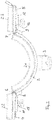
- a headrest for operating tables is generally designated 1.
- This headrest 1 initially has an arcuate support element 2, which serves to support an occiput of a patient.
- This support element 2 has on its rear side a fastening element 3 for fastening a retaining arm, not shown, of an operating table.
- the headrest 1 has a first holding element 4 and a second holding element 5.
- Each of these two holding elements 4, 5 serves for lateral abutment on one side of a head of a patient.
- Both holding elements 4, 5 are hinged relative to the support member 2 pivotally.
- the first holding element 4 is articulated about a first axis of rotation 6 in a first edge region of the support element 2 and the second holding element 5 about a second axis of rotation 7 in the second edge region of the support element individually pivotable on the support element 2.
- each holding element 4, 5 in a pivoted position is in each case bounded by an end stop 8, 9 arranged on the outside of the support element 2.
- These two end stops 8, 9 may be screwed to the support member 2, for example.
- Corresponding fastening screws are designated by 10.
- the respective abutment surface 8a, 9a of the respective end stop 8, 9 is further spaced from the adjacent outer edge 2a or 2b of the support element 2 than the respective axis of rotation 6, 7.
- the exact distance of the respective stop surface 8a, 9a from the associated outer edge 2a, 2b of the support element 2 determines the maximum pivotability of the holding elements 4, 5 in swung-out position.
- the end stops 8, 9 are arranged so that the holding elements 4 and 5 are in the pivoted position approximately in a horizontal position. This position is in Fig. 2 shown. In this maximally pivoted-out position of the two holding elements 4, 5, each holding element 4, 5 can serve as a support surface for an anesthetist or the like before the actual beginning of an operation.
- each retaining element 4, 5 is in each case a displaceable slider 11, 12, which is designed such that it is displaceable between a first end position, in which it does not project beyond the edge of the retaining element 4, 5 facing the support element 2, and a second end position, in which it bears against the abutment surface 8a, 9a the associated end stop 8, 9 is applied.
- the first end position is in Fig. 4 left for the retaining element 4 and the second end position is in Fig. 4 shown right for the second holding element 5.
- the slider 11, 12 is guided on the holding element 4, 5 respectively.
- the slider 11, 12 on the back have guide pins which engage in guides on the retaining element, which is not shown in the drawing.
- the respective slider 11, 12 has a slot 13, 14, in which a locking screw 15, 16 engages.
- This locking screw 15, 16 is screwed into a corresponding bore 17, 18 with internal thread in the holding element 4, 5.
- the headrest 1 also preferably has two fastening straps, namely a first fastening strap 19 for enclosing the forehead of the patient and a second fastening strap 20 for enclosing the chin of the patient. Both straps 19, 20 are preferably variable in length and alternatively or additionally formed elastically.
- Both the arcuate support element 2 and the two holding elements 4 and 5 and possibly the fastening straps 19, 20 are each provided on the inside of the patient facing the head with suitable pads 21, 22, 23, 24 and 25.
- the patient Before starting an operation, in particular a shoulder operation, the patient is placed in a supine position on an operating table, not shown, in such a way that his head or back of the head is on the arcuate support element 2.
- the two holding elements 4 and 5 are fully swung open, ie in the position according to Fig. 2 , so arranged approximately horizontally.
- the patient may be assisted by an anesthetist
- be intubated which can be supported on one of the two holding elements 4 or 5.
- the head is already securely held in the arcuate support element 2.
- the two holding elements 4 and 5 are pivoted vertically upwards and the two sliders 11 and 12 are moved after loosening the fastening screws 17 and 18 down until they abut respectively on the stop surface 8a, 9a of the end stop 8 and 9 respectively , This ensures that the two holding elements 4, 5 can not unintentionally fold down again before the final fixation of the headrest 1 on the head of the patient.
- the two fastening straps 19 and 20 are closed and tightened. In this case, the two holding elements 4 and 5 can pivot further inward until it touches the respective head side of the patient.
- the two end stops 8, 9 may also be an integral part of the arcuate support element 2, so be molded.
- the support element can also be divided symmetrically into two halves in the region of the fastening element 3 and held together by the fastening element 3.
Landscapes
- Health & Medical Sciences (AREA)
- Neurosurgery (AREA)
- Otolaryngology (AREA)
- Engineering & Computer Science (AREA)
- Biomedical Technology (AREA)
- Life Sciences & Earth Sciences (AREA)
- Animal Behavior & Ethology (AREA)
- General Health & Medical Sciences (AREA)
- Public Health (AREA)
- Veterinary Medicine (AREA)
- Accommodation For Nursing Or Treatment Tables (AREA)
Abstract
Die Erfindung betrifft eine Kopfstütze für Operationstische mit einem bogenförmigen Stützelement (2) zur Auflage eines Hinterkopfes eines Patienten und mit einem ersten und einem zweiten Halteelement (4,5) zur seitlichen Anlage am Kopf des Patienten, wobei die beiden Halteelemente (4,5) gegenüber dem Stützelement (2) verschwenkbar sind, wobei wenigstens ein Befestigungsband (19,20) zum Verbinden der vorderseitigen Endbereiche der beiden Halteelemente (4,5) und zur Anlage am vorderen Kopfbereich des Patienten vorgesehen ist.The invention relates to a headrest for operating tables with an arcuate support element (2) for supporting an occiput of a patient and having a first and a second holding element (4,5) for lateral contact with the head of the patient, wherein the two holding elements (4,5) relative to the support element (2) are pivotable, wherein at least one fastening band (19,20) for connecting the front end portions of the two holding elements (4,5) and for abutment on the front head portion of the patient is provided.
Dabei ist vorgesehen, dass das erste und das zweite Halteelement (4,5) jeweils um eine erste bzw. zweite Drehachse (6,7) einzeln verschwenkbar am Stützelement (2) angelenkt sind, wobei der Verschwenkweg jedes Halteelementes (4,5) in aufgeschwenkter Lage desselben durch jeweils einen an der Außenseite des Stützelementes (2) angeordeneten Endanschlag (8,9) begrenzt ist.

Description
Die Erfindung betrifft eine Kopfstütze für Operationstische mit einem bogenförmigen Stützelement zur Auflage eines Hinterkopfes eines Patienten und mit einem ersten und einem zweiten Halteelement zur seitlichen Anlage am Kopf des Patienten, wobei die beiden Halteelemente gegenüber dem Stützelement verschwenkbar sind, wobei wenigstens ein Befestigungsband zum Verbinden der vorderseitigen Endbereiche der beiden Halteelemente und zur Anlage am vorderen Kopfbereich des Patienten vorgesehen ist.The invention relates to a headrest for operating tables with an arcuate support member for supporting an occiput of a patient and with a first and a second holding element for lateral contact with the head of the patient, wherein the two holding elements relative to the support element are pivotable, wherein at least one fastening band for connecting the front end portions of the two holding elements and is intended to rest on the front head region of the patient.
Vor allem bei Operationen im Schulterbereich wird ein Patient in Rückenlage auf einen Operationstisch gelegt. Zur sicheren Abstützung des Kopfes ist eine Kopfstütze am Operationstisch befestigt, mittels welcher einer sichere Fixierung des Kopfes während der Operation erfolgt, um sicherzustellen, dass die Operation mit geringstmöglichem Risiko für den Patienten stattfinden kann.Especially in operations in the shoulder area, a patient is placed supine on an operating table. For secure support of the head, a head restraint is attached to the operating table by means of which a secure fixation of the head is made during surgery to ensure that the surgery can take place with the least possible risk to the patient.
Aus
Der Aufbau der Kopfstütze ist aufgrund des in dieses integrierten Zahnradgetriebes jedoch relativ aufwendig und erfordert einen nicht unbeachtlichen Raumbedarf. Außerdem können beide Halteelemente nur gleichzeitig und synchron bedient werden, so dass eine exakte Anpassung an die jeweilige Kopfform schwierig oder nicht möglich ist, insbesondere dann, wenn sich der Kopf des Patienten nicht genau in der Mitte des Aufnahmebereiches befindet.However, the structure of the headrest is relatively expensive due to the integrated gear in this gear and requires a not inconsiderable space. In addition, both retaining elements can be operated only simultaneously and synchronously, so that an exact adaptation to the respective head shape is difficult or impossible, especially if the head of the patient is not exactly in the middle of the receiving area.
Aufgabe der Erfindung ist es, eine Kopfstütze für Operationstische zu schaffen, die einfach aufgebaut, leicht zu bedienen und an die jeweilige Kopflagerungssituation sowie die jeweilige Kopfform anpassbar ist.The object of the invention is to provide a headrest for operating tables, which is simple in construction, easy to use and adaptable to the respective head storage situation and the respective head shape.
Diese Aufgabe wird erfindungsgemäß dadurch gelöst, dass das erste und das zweite Halteelement jeweils um eine erste bzw. zweite Drehachse einzeln verschwenkbar am Stützelement angelenkt sind, wobei der Verschwenkweg jedes Halteelementes in aufgeschwenkter Lage desselben durch jeweils einen an der Außenseite des Stützelementes angeordneten Endanschlag begrenzt ist.This object is achieved in that the first and the second holding element are each pivoted about a first or second axis of rotation individually pivotable on the support element, wherein the Verschwenkweg each holding element in the pivoted position of the same is limited by one arranged on the outside of the support element end stop ,
Die Kopfstütze ist somit einfach aufgebaut, da die beiden Halteelemente jeweils einzeln am Stützelement angelenkt sind und kein Kopplungsgetriebe vorgesehen ist. Da jedes Halteelement individuell verschwenkt werden kann, ist eine genaue Anpassung an die Kopfform bzw. Kopflagerungsposition möglich, d.h. beide Halteelemente können individuell weit eingeschwenkt werden, um jeweils an der jeweiligen Seite des Kopfes des Patienten anzuliegen. In maximal ausgeschwenkter Lage liegen beide Halteelemente jeweils am Endanschlag des Stützelementes an, so dass sie sich in annähernd waagerechter Position befinden und die Halteelemente in dieser Lage als sichere Abstützfläche für einen Anästhesisten während der Einleitung der Narkose oder bei anderen Aktivitäten dienen. Dabei ist der Kopf des Patienten aufgrund der bogenförmigen Ausbildung des Stützelementes auch in dieser Position sicher gehalten. Durch einfaches individuelles Verschwenken der Halteelemente und Verbindung der Endbereiche der beiden Halteelemente mit wenigstens einem Befestigungsband ist anschließend eine sichere helmartige Abstützung des Kopfes des Patienten in der Kopfstütze gewährleistet bevor die Operation beginnt.The headrest is thus simple, since the two holding elements are individually articulated on the support element and no coupling gear is provided. Since each retaining element can be pivoted individually, an exact adaptation to the head shape or head mounting position is possible, ie both retaining elements can be pivoted individually far to abut each on the respective side of the head of the patient. In maximum swung out Location are both holding elements respectively on the end stop of the support element, so that they are in approximately horizontal position and serve the holding elements in this position as a safe support surface for an anesthetist during the induction of anesthesia or other activities. In this case, the head of the patient is held securely in this position due to the arcuate design of the support element. By simple individual pivoting of the holding elements and connection of the end portions of the two holding elements with at least one fastening band then a secure helmet-like support of the head of the patient is guaranteed in the headrest before the operation begins.
In bevorzugter Ausgestaltung ist vorgesehen, dass die jeweilige Anschlagfläche des jeweiligen Endanschlages vom angrenzenden Außenrand des Stützelementes weiter beabstandet ist als die jeweilige Drehachse. Durch diese Anordnung der Endanschläge ist gewährleistet, dass in aufgeschwenkter Lage der beiden Halteelemente diese in etwa waagerechter Lage am Endanschlag anliegen.In a preferred embodiment, it is provided that the respective stop surface of the respective end stop from the adjacent outer edge of the support element is further spaced than the respective axis of rotation. This arrangement of the end stops ensures that lie in the pivoted position of the two holding elements this approximately horizontal position on the end stop.
In ganz besonders bevorzugter Ausgestaltung ist vorgesehen, dass an der Außenseite jedes Halteelementes jeweils ein verschiebbares Gleitstück angeordnet ist, welches so ausgebildet ist, dass es zwischen einer ersten Endlage, in welcher es den dem Stützelement zugewandten Rand des Halteelementes nicht überragt, und einer zweiten Endlage verschiebbar ist, in welcher es an der Anschlagfläche des zugeordneten Endanschlages anliegt. Durch dieses Gleitstück am jeweiligen Halteelement lässt sich die Bedienung der Kopfstütze wesentlich vereinfachen. Dazu wird das jeweilige Halteelement zunächst in eine vertikale Position verschwenkt und das Gleitstück über den Rand des Halteelementes hinaus bis zum zugeordneten Endanschlag verschoben, bis es an der Anschlagfläche des Endanschlages anliegt. Dadurch ist das jeweilige Halteelement durch das am zugeordneten Endanschlag anliegende Gleitstück gegen ein ungewolltes Herunterklappen nach außen aus der vertikalen Lage gesichert, es kann anschließend nur noch weiter nach innen gegen die Seite des Kopfes des Patienten verschwenkt werden.In a particularly preferred embodiment, it is provided that on the outer side of each holding element in each case a displaceable slider is arranged, which is designed so that it does not protrude between a first end position, in which it the support member facing edge of the holding element, and a second end position is displaceable, in which it bears against the stop surface of the associated end stop. By this slider on the respective holding element, the operation of the headrest can be much easier. For this purpose, the respective holding element is first pivoted into a vertical position and the slider over the edge of the holding element also moved to the associated end stop until it bears against the stop surface of the end stop. As a result, the respective holding element is secured by the voltage applied to the associated end stop slider against accidental folding down out of the vertical position, it can then be pivoted only further inward against the side of the patient's head.
Dabei ist bevorzugt vorgesehen, dass das Gleitstück am Halteelement geführt ist. Dazu kann das Gleitstück rückseitig Führungszapfen aufweisen, die in Führungen am Halteelemnt eingreifen.It is preferably provided that the slider is guided on the holding element. For this purpose, the slider may on the back have guide pins which engage in guides on Halteelemnt.
Bevorzugt ist außerdem vorgesehen, dass das Gleitsück ein Langloch aufweist, in welches eine Feststellschraube eingreift. Durch Anziehen der Feststellschraube kann das Gleitstück in der jeweiligen Position, in der Regel in einer der beiden Endlagen, arretiert werden.Preferably, it is also provided that the sliding piece has a slot in which a locking screw engages. By tightening the locking screw, the slider can be locked in the respective position, usually in one of the two end positions.
In weiterer Ausgestaltung ist vorgesehen, dass zwei Befestigungsbänder vorgesehen sind, wobei das erste Befestigungsband die Stirn des Patienten und das zweite Befestigungsband das Kinn des Patienten umschließt. Dadurch ist eine nahezu helmartige Sicherung des Kopfes gewährleistet.In a further embodiment, it is provided that two fastening straps are provided, wherein the first fastening strap surrounds the forehead of the patient and the second fastening strap encloses the chin of the patient. This ensures a nearly helmet-like protection of the head.
Dabei ist vorteilhaft vorgesehen, dass das jeweilige Befestigungsband längenveränderbar ausgebildet ist und zusätzlich oder alternativ aus einem elastischen Material besteht. Durch diese beiden Ausgestaltungen ist eine unmittelbare Anlage der beiden Halteelemente an den Kopfseiten des Patienten sowie eine sichere Anlage im Kinnbereich des Patienten gewährleistet.It is advantageously provided that the respective fastening strap is formed variable in length and additionally or alternatively consists of an elastic material. These two embodiments ensure a direct contact of the two holding elements on the head sides of the patient as well as a secure abutment in the chin region of the patient.
Die Erfindung ist nachstehend anhand der Zeichnung beispielsweise näher erläutert. Diese zeigt in
-
Fig. 1 eine perspektivische Darstellung einer Kopfstütze in geschlossener Lage, -
Fig. 2 eine Draufsicht auf die Kopfstütze in maximal aufgeschwenkter Lage, -
Fig. 3 eine Seitenansicht der Kopfstütze in geschlossener Lage und -
Fig. 4 einen Schnitt gemäß Linie A-A inFig. 3 .
-
Fig. 1 a perspective view of a headrest in a closed position, -
Fig. 2 a top view of the headrest in maximum pivoted position, -
Fig. 3 a side view of the headrest in a closed position and -
Fig. 4 a section along line AA inFig. 3 ,
Eine Kopfstütze für Operationstische ist allgemein mit 1 bezeichnet. Diese Kopfstütze 1 weist zunächst ein bogenförmiges Stützelement 2 auf, das zur Auflage eines Hinterkopfes eines Patienten dient. Dieses Stützelement 2 weist an seiner Rückseite ein Befestigungselement 3 zur Befestigung eines nicht dargestellten Haltearmes eines Operationstisches auf.A headrest for operating tables is generally designated 1. This headrest 1 initially has an
Neben dem bogenförmigen Stützelement 2 weist die Kopfstütze 1 ein erstes Halteelement 4 und ein zweites Halteelement 5 auf. Jedes dieser beiden Halteelemente 4, 5 dient zur seitlichen Anlage an einer Seite eines Kopfes eines Patienten. Beide Halteelemente 4, 5 sind gegenüber dem Stützelement 2 verschwenkbar angelenkt. Dabei ist das erste Halteelement 4 um eine erste Drehachse 6 in einem ersten Randbereich des Stützelementes 2 und das zweite Halteelement 5 um eine zweite Drehachse 7 im zweiten Randbereich des Stützelementes jeweils individuell schwenkbar am Stützelement 2 angelenkt.In addition to the
Der Verschwenkweg jedes Halteelementes 4, 5 in aufgeschwenkter Lage (
An der Außenseite jedes Halteelementes 4, 5 ist jeweils ein verschiebbares Gleitstück 11, 12 angeordnet, das so ausgebildet ist, dass es zwischen einer ersten Endlage, in welcher es das dem Stützelement 2 zugewandten Rand des Halteelementes 4, 5 nicht überragt, und einer zweiten Endlage verschiebbar ist, in welcher es an der Anschlagfläche 8a, 9a des zugeordneten Endanschlages 8, 9 anliegt. Die erste Endlage ist in
Das jeweilige Gleitstück 11, 12 weist ein Langloch 13, 14 auf, in welches eine Feststellschraube 15, 16 eingreift. Diese Feststellsschraube 15, 16 ist dabei in eine entsprechende Bohrung 17, 18 mit Innengewinde im Halteelement 4, 5 eingeschraubt.The
Die Kopfstütze 1 weist darüber hinaus vorzugsweise zwei Befestigungsbänder auf, nämlich ein erstes Befestigungsband 19 zum Umschließen der Stirn des Patienten und ein zweites Befestigungsband 20 zum Umschließen des Kinns des Patienten. Beide Befestigungsbänder 19, 20 sind vorzugsweise längenveränderbar und alternativ oder zusätzlich elastisch ausgebildet.The headrest 1 also preferably has two fastening straps, namely a
Sowohl das bogenförmige Stützelement 2 als auch die beiden Halteelemente 4 und 5 und ggf. die Befestigungsbänder 19, 20 sind jeweils auf der dem Kopf des Patienten zugewandten Innenseite mit geeigneten Polstern 21, 22, 23, 24 und 25 versehen.Both the
Vor Beginn einer Operation, insbesondere einer Schulteroperation wird der Patient in Rückenlage auf einen nicht dargestellten Operationstisch gelegt, und zwar so, dass sich sein Kopf bzw. Hinterkopf auf dem bogenförmigen Stützelement 2 befindet. In dieser Situation sind die beiden Halteelemente 4 und 5 vollständig aufgeschwenkt, d.h. in der Position gemäß
Im Anschluss daran, werden die beiden Halteelemente 4 und 5 vertikal nach oben geschwenkt und die beiden Gleitstücke 11 und 12 werden nach Lösen der Befestigungsschrauben 17 und 18 nach unten verschoben, bis sie jeweils an der Anschlagfläche 8a, 9a des Endanschlages 8 bzw. 9 anliegen. Dadurch ist gewährleistet, dass die beiden Halteelemente 4, 5 vor der endgültigen Fixierung der Kopfstütze 1 am Kopf des Patienten nicht ungewollt wieder herunterklappen können. Schließlich werden die beiden Befestigungsbänder 19 und 20 geschlossen und angezogen. Dabei können die beiden Halteelemente 4 und 5 noch weiter nach innen bis zur Anlage an die jeweilige Kopfseite des Patienten einschwenken.Following this, the two holding
Je weiter die Gleitstücke 11, 12 nach unten auf die Anschlagflächen 8a, 9a geschoben werden, neigen sich die Halteelemente 4, 5 immer weiter in Richtung des Stützelementes 2, so dass die Kopfstütze 1 immer enger wird.The farther the
Zum Lösen der Kopfstütze 1 wird umgekehrt verfahren: Zunächst werden die Befestigungsbänder 10 und 20 und die Befestigungsschrauben 17 und 18 gelöst und danach werden die Gleitstücke 11, 12 nach oben in die erste Endlage geschoben und dort durch Einschrauben der Befetigungsschrauben17 und 18 arretiert. Die Halteelemente 4 und 5 sind dadurch freigegeben und können in die zweite Endlage verschwenkt (geöffnet) werden.To solve the headrest 1 is reversed procedure: First, the
Die beiden Endanschläge 8, 9 können auch integraler Bestandteil des bogenförmigen Stützelementes 2 sein, also angeformt sein. Das Stützelement kann auch im Bereich des Befestigungselementes 3 symmetrisch in zwei Hälften unterteilt sein und vom Befestigungselement 3 zusammengehalten werden.The two end stops 8, 9 may also be an integral part of the
- 11
- Kopfstützeheadrest
- 22
- Stützelementsupport element
- 2a, 2b2a, 2b
- StützelementaußenrandSupporting element outer edge
- 33
- Befestigungselementfastener
- 4, 54, 5
- Halteelementretaining element
- 66
- erste Drehachsefirst axis of rotation
- 77
- zweite Drehachsesecond axis of rotation
- 8, 98, 9
- Endanschlagend stop
- 8a, 9a8a, 9a
- Anschlagflächestop surface
- 1010
- Befestigungsschraubefixing screw
- 11, 1211, 12
- Gleitstückslide
- 13, 1413, 14
- LanglochLong hole
- 15, 1615, 16
- Feststellschraubelocking screw
- 17, 1817, 18
- Bohrungdrilling
- 19, 2019, 20
- Befestigungsbandfixing tape
- 21 - 2521 - 25
- Polsterpad
Claims (8)
dadurch gekennzeichnet,
dass das erste und das zweite Halteelement (4,5) jeweils um eine erste bzw. zweite Drehachse (6,7) einzeln verschwenkbar am Stützelement (2) angelenkt sind, wobei der Verschwenkweg jedes Halteelementes (4,5) in aufgeschwenkter Lage desselben durch jeweils einen an der Außenseite des Stützelementes (2) angeordeneten Endanschlag (8,9) begrenzt ist.Headrest for operating tables with an arcuate support element (2) for supporting an occiput of a patient and with a first and a second holding element (4,5) for lateral contact with the head of the patient, wherein the two holding elements (4,5) with respect to the support element ( 2) are pivotable, wherein at least one fastening band (19, 20) is provided for connecting the front-side end regions of the two retaining elements (4, 5) and for bearing against the front head region of the patient,
characterized,
in that the first and the second holding element (4, 5) are articulated individually pivotable about a first or second axis of rotation (6, 7) on the support element (2), wherein the pivotal path of each holding element (4, 5) in the pivoted-on position thereof is through each one on the outside of the support element (2) arranged end stop (8,9) is limited.
dadurch gekennzeichnet,
dass die jeweilige Anschlagfläche (8a,9a) des jeweiligen Endanschlages (8,9) vom angrenzenden Außenrand (2a,2b) des Stützelementes (2) weiter beabstandet ist als die jeweilige Drehachse (6,7).Headrest according to claim 1,
characterized,
that the respective stop surface (8a, 9a) of the respective end stop (8,9) from the adjacent outer edge (2a, 2b) of the supporting element (2) is spaced further than the respective axis of rotation (6,7).
dadurch gekennzeichnet,
dass an der Außenseite jedes Halteelementes (4,5) jeweils ein verschiebbares Gleitstück (11,12) angeordnet ist, welches so ausgebildet ist, dass es zwischen einer ersten Endlage, in welcher es den dem Stützelement (2) zugewandten Rand des Halteelementes (4,5) nicht überragt, und einer zweiten Endlage verschiebbar ist, in welcher es an der Anschlagfläche (8a,9a) des zugeordneten Endanschlages (8,9) anliegt.Headrest according to claim 2,
characterized,
that on the outer side of each holding element (4.5) in each case a displaceable slide (11,12) is arranged, which is formed so that between a first end position in which it (the side facing the support element (2) edge of the retaining element 4 , 5) is not projected, and a second end position is displaceable, in which it rests against the stop surface (8a, 9a) of the associated end stop (8,9).
dadurch gekennzeichnet,
dass das Gleitstück (11,12) am Halteelement (4,5) geführt ist.Headrest according to claim 3,
characterized,
that the slider (11,12) is guided on the holding element (4.5).
dadurch gekennzeichnet,
dass das Gleitsück (11,12) ein Langloch (13,14) aufweist, in welches eine Feststellschraube (15,16) eingreift.Headrest according to claim 4,
characterized,
in that the sliding piece (11, 12) has a slot (13, 14) in which a locking screw (15, 16) engages.
dadurch gekennzeichnet,
dass zwei Befestigungsbänder (19,20) vorgesehen sind, wobei das erste Befestigungsband (19) die Stirn des Patienten und das zweite Befestigungsband (20) das Kinn des Patienten umschließt.Headrest according to one of claims 1 to 5,
characterized,
in that two fastening straps (19, 20) are provided, wherein the first fastening strap (19) encloses the forehead of the patient and the second fastening strap (20) encloses the chin of the patient.
dadurch gekennzeichnet,
dass das jeweilige Befestigungsband (19,20) längenveränderbar ausgebildet ist.Headrest according to one of claims 1 to 6,
characterized,
that the respective fastening band (19, 20) is variable in length.
dadurch gekennzeichnet,
dass das jeweilige Befestigungsband (19,20) aus einem elastischen Material besteht.Headrest according to one of claims 1 to 7,
characterized,
that the respective fastening band (19, 20) consists of an elastic material.
Applications Claiming Priority (1)
| Application Number | Priority Date | Filing Date | Title |
|---|---|---|---|
| DE202017105275.3U DE202017105275U1 (en) | 2017-09-01 | 2017-09-01 | Headrest for operating tables |
Publications (2)
| Publication Number | Publication Date |
|---|---|
| EP3449888A1 true EP3449888A1 (en) | 2019-03-06 |
| EP3449888B1 EP3449888B1 (en) | 2020-03-18 |
Family
ID=64745282
Family Applications (1)
| Application Number | Title | Priority Date | Filing Date |
|---|---|---|---|
| EP18187953.7A Active EP3449888B1 (en) | 2017-09-01 | 2018-08-08 | Head support for a surgical table |
Country Status (2)
| Country | Link |
|---|---|
| EP (1) | EP3449888B1 (en) |
| DE (1) | DE202017105275U1 (en) |
Cited By (1)
| Publication number | Priority date | Publication date | Assignee | Title |
|---|---|---|---|---|
| EP3900690A1 (en) * | 2020-04-22 | 2021-10-27 | Warsaw Orthopedic, Inc. | Head support and method for use of the head support for positioning a patient relative to a surgical frame |
Families Citing this family (1)
| Publication number | Priority date | Publication date | Assignee | Title |
|---|---|---|---|---|
| CN113648078B (en) * | 2021-09-27 | 2022-09-27 | 苏州市立医院 | Puncture positioning auxiliary device that blood vessel of brain intervenes |
Citations (4)
| Publication number | Priority date | Publication date | Assignee | Title |
|---|---|---|---|---|
| US4034748A (en) * | 1975-10-28 | 1977-07-12 | Winner Stephen E | Spinal restraint device |
| US20120124747A1 (en) * | 2010-11-18 | 2012-05-24 | Orlando Soto | Padded head support |
| EP2724701B1 (en) | 2012-10-29 | 2015-04-29 | Maquet GmbH | Head support for operating tables |
| CN207627563U (en) * | 2017-04-19 | 2018-07-20 | 曲敬茹 | A kind of ophthalmologic operation head fixing device |
-
2017
- 2017-09-01 DE DE202017105275.3U patent/DE202017105275U1/en active Active
-
2018
- 2018-08-08 EP EP18187953.7A patent/EP3449888B1/en active Active
Patent Citations (4)
| Publication number | Priority date | Publication date | Assignee | Title |
|---|---|---|---|---|
| US4034748A (en) * | 1975-10-28 | 1977-07-12 | Winner Stephen E | Spinal restraint device |
| US20120124747A1 (en) * | 2010-11-18 | 2012-05-24 | Orlando Soto | Padded head support |
| EP2724701B1 (en) | 2012-10-29 | 2015-04-29 | Maquet GmbH | Head support for operating tables |
| CN207627563U (en) * | 2017-04-19 | 2018-07-20 | 曲敬茹 | A kind of ophthalmologic operation head fixing device |
Cited By (1)
| Publication number | Priority date | Publication date | Assignee | Title |
|---|---|---|---|---|
| EP3900690A1 (en) * | 2020-04-22 | 2021-10-27 | Warsaw Orthopedic, Inc. | Head support and method for use of the head support for positioning a patient relative to a surgical frame |
Also Published As
| Publication number | Publication date |
|---|---|
| DE202017105275U1 (en) | 2018-12-06 |
| EP3449888B1 (en) | 2020-03-18 |
Similar Documents
| Publication | Publication Date | Title |
|---|---|---|
| EP3003198B1 (en) | Adapter device for an operating table | |
| DE69633302T2 (en) | REGULATORY POSITIONING SYSTEM FOR BONE | |
| DE69405798T2 (en) | Adapter and closure unit for trocar equipment | |
| AT399018B (en) | FURNITURE HINGE | |
| DE19606092A1 (en) | Joint support, in particular knee support | |
| EP3100681B1 (en) | Radiation protection assembly | |
| DE102014019715A1 (en) | Orthosis with inclination adjustment device | |
| EP3449888B1 (en) | Head support for a surgical table | |
| DE2043679A1 (en) | Closure on ski boots | |
| DE2951664A1 (en) | Medical instrument with two adjustable and lockable arms - has housing on one arm, slidably guided on other arm rail, with spring loaded lock release member | |
| DE102014101009A1 (en) | Bone spreader with twistable valves | |
| EP1464367B1 (en) | Snowboard binding | |
| EP2292112B1 (en) | Helmet with eye protection | |
| EP0372406A2 (en) | Adjustable chin strap for motorcycle protection helmets | |
| EP3421016B1 (en) | Dynamic hand orthosis | |
| DE3516480A1 (en) | FURNITURE HINGE | |
| EP0572474B1 (en) | Constriction device for reducing the blood flow in parts of the body | |
| DE202007000136U1 (en) | Jalousie for opening of e.g. window, has end guide rail pivotable around pivoting axis, and locking mechanism arranged between guide rail and edge pieces, where mechanism holds adjusted pivoting position of guide rail around axis | |
| DE102014101218A1 (en) | fitting assembly | |
| EP2633780A1 (en) | Device for stabilising the running behaviour of a movable furniture part in a furniture body | |
| EP3988049B1 (en) | Distractor device | |
| EP2810576B1 (en) | Fixing system for a helmet shell | |
| DE102016010241B4 (en) | Polycentric swivel-sliding joint and knee orthosis herewith | |
| DE102004004576A1 (en) | Detachable clamp for a helmet strap | |
| DE102015105450A1 (en) | Device with parallel gripping surface |
Legal Events
| Date | Code | Title | Description |
|---|---|---|---|
| PUAI | Public reference made under article 153(3) epc to a published international application that has entered the european phase |
Free format text: ORIGINAL CODE: 0009012 |
|
| STAA | Information on the status of an ep patent application or granted ep patent |
Free format text: STATUS: THE APPLICATION HAS BEEN PUBLISHED |
|
| AK | Designated contracting states |
Kind code of ref document: A1 Designated state(s): AL AT BE BG CH CY CZ DE DK EE ES FI FR GB GR HR HU IE IS IT LI LT LU LV MC MK MT NL NO PL PT RO RS SE SI SK SM TR |
|
| AX | Request for extension of the european patent |
Extension state: BA ME |
|
| STAA | Information on the status of an ep patent application or granted ep patent |
Free format text: STATUS: REQUEST FOR EXAMINATION WAS MADE |
|
| 17P | Request for examination filed |
Effective date: 20190730 |
|
| RBV | Designated contracting states (corrected) |
Designated state(s): AL AT BE BG CH CY CZ DE DK EE ES FI FR GB GR HR HU IE IS IT LI LT LU LV MC MK MT NL NO PL PT RO RS SE SI SK SM TR |
|
| GRAP | Despatch of communication of intention to grant a patent |
Free format text: ORIGINAL CODE: EPIDOSNIGR1 |
|
| STAA | Information on the status of an ep patent application or granted ep patent |
Free format text: STATUS: GRANT OF PATENT IS INTENDED |
|
| INTG | Intention to grant announced |
Effective date: 20191021 |
|
| GRAS | Grant fee paid |
Free format text: ORIGINAL CODE: EPIDOSNIGR3 |
|
| GRAA | (expected) grant |
Free format text: ORIGINAL CODE: 0009210 |
|
| STAA | Information on the status of an ep patent application or granted ep patent |
Free format text: STATUS: THE PATENT HAS BEEN GRANTED |
|
| AK | Designated contracting states |
Kind code of ref document: B1 Designated state(s): AL AT BE BG CH CY CZ DE DK EE ES FI FR GB GR HR HU IE IS IT LI LT LU LV MC MK MT NL NO PL PT RO RS SE SI SK SM TR |
|
| REG | Reference to a national code |
Ref country code: GB Ref legal event code: FG4D Free format text: NOT ENGLISH |
|
| REG | Reference to a national code |
Ref country code: DE Ref legal event code: R096 Ref document number: 502018000977 Country of ref document: DE |
|
| REG | Reference to a national code |
Ref country code: AT Ref legal event code: REF Ref document number: 1245071 Country of ref document: AT Kind code of ref document: T Effective date: 20200415 Ref country code: IE Ref legal event code: FG4D Free format text: LANGUAGE OF EP DOCUMENT: GERMAN |
|
| PG25 | Lapsed in a contracting state [announced via postgrant information from national office to epo] |
Ref country code: RS Free format text: LAPSE BECAUSE OF FAILURE TO SUBMIT A TRANSLATION OF THE DESCRIPTION OR TO PAY THE FEE WITHIN THE PRESCRIBED TIME-LIMIT Effective date: 20200318 Ref country code: FI Free format text: LAPSE BECAUSE OF FAILURE TO SUBMIT A TRANSLATION OF THE DESCRIPTION OR TO PAY THE FEE WITHIN THE PRESCRIBED TIME-LIMIT Effective date: 20200318 Ref country code: NO Free format text: LAPSE BECAUSE OF FAILURE TO SUBMIT A TRANSLATION OF THE DESCRIPTION OR TO PAY THE FEE WITHIN THE PRESCRIBED TIME-LIMIT Effective date: 20200618 |
|
| REG | Reference to a national code |
Ref country code: NL Ref legal event code: MP Effective date: 20200318 |
|
| PG25 | Lapsed in a contracting state [announced via postgrant information from national office to epo] |
Ref country code: BG Free format text: LAPSE BECAUSE OF FAILURE TO SUBMIT A TRANSLATION OF THE DESCRIPTION OR TO PAY THE FEE WITHIN THE PRESCRIBED TIME-LIMIT Effective date: 20200618 Ref country code: HR Free format text: LAPSE BECAUSE OF FAILURE TO SUBMIT A TRANSLATION OF THE DESCRIPTION OR TO PAY THE FEE WITHIN THE PRESCRIBED TIME-LIMIT Effective date: 20200318 Ref country code: GR Free format text: LAPSE BECAUSE OF FAILURE TO SUBMIT A TRANSLATION OF THE DESCRIPTION OR TO PAY THE FEE WITHIN THE PRESCRIBED TIME-LIMIT Effective date: 20200619 Ref country code: LV Free format text: LAPSE BECAUSE OF FAILURE TO SUBMIT A TRANSLATION OF THE DESCRIPTION OR TO PAY THE FEE WITHIN THE PRESCRIBED TIME-LIMIT Effective date: 20200318 Ref country code: SE Free format text: LAPSE BECAUSE OF FAILURE TO SUBMIT A TRANSLATION OF THE DESCRIPTION OR TO PAY THE FEE WITHIN THE PRESCRIBED TIME-LIMIT Effective date: 20200318 |
|
| REG | Reference to a national code |
Ref country code: LT Ref legal event code: MG4D |
|
| PG25 | Lapsed in a contracting state [announced via postgrant information from national office to epo] |
Ref country code: NL Free format text: LAPSE BECAUSE OF FAILURE TO SUBMIT A TRANSLATION OF THE DESCRIPTION OR TO PAY THE FEE WITHIN THE PRESCRIBED TIME-LIMIT Effective date: 20200318 |
|
| PG25 | Lapsed in a contracting state [announced via postgrant information from national office to epo] |
Ref country code: RO Free format text: LAPSE BECAUSE OF FAILURE TO SUBMIT A TRANSLATION OF THE DESCRIPTION OR TO PAY THE FEE WITHIN THE PRESCRIBED TIME-LIMIT Effective date: 20200318 Ref country code: SK Free format text: LAPSE BECAUSE OF FAILURE TO SUBMIT A TRANSLATION OF THE DESCRIPTION OR TO PAY THE FEE WITHIN THE PRESCRIBED TIME-LIMIT Effective date: 20200318 Ref country code: IS Free format text: LAPSE BECAUSE OF FAILURE TO SUBMIT A TRANSLATION OF THE DESCRIPTION OR TO PAY THE FEE WITHIN THE PRESCRIBED TIME-LIMIT Effective date: 20200718 Ref country code: PT Free format text: LAPSE BECAUSE OF FAILURE TO SUBMIT A TRANSLATION OF THE DESCRIPTION OR TO PAY THE FEE WITHIN THE PRESCRIBED TIME-LIMIT Effective date: 20200812 Ref country code: EE Free format text: LAPSE BECAUSE OF FAILURE TO SUBMIT A TRANSLATION OF THE DESCRIPTION OR TO PAY THE FEE WITHIN THE PRESCRIBED TIME-LIMIT Effective date: 20200318 Ref country code: SM Free format text: LAPSE BECAUSE OF FAILURE TO SUBMIT A TRANSLATION OF THE DESCRIPTION OR TO PAY THE FEE WITHIN THE PRESCRIBED TIME-LIMIT Effective date: 20200318 Ref country code: CZ Free format text: LAPSE BECAUSE OF FAILURE TO SUBMIT A TRANSLATION OF THE DESCRIPTION OR TO PAY THE FEE WITHIN THE PRESCRIBED TIME-LIMIT Effective date: 20200318 Ref country code: LT Free format text: LAPSE BECAUSE OF FAILURE TO SUBMIT A TRANSLATION OF THE DESCRIPTION OR TO PAY THE FEE WITHIN THE PRESCRIBED TIME-LIMIT Effective date: 20200318 |
|
| REG | Reference to a national code |
Ref country code: DE Ref legal event code: R097 Ref document number: 502018000977 Country of ref document: DE |
|
| PLBE | No opposition filed within time limit |
Free format text: ORIGINAL CODE: 0009261 |
|
| STAA | Information on the status of an ep patent application or granted ep patent |
Free format text: STATUS: NO OPPOSITION FILED WITHIN TIME LIMIT |
|
| PG25 | Lapsed in a contracting state [announced via postgrant information from national office to epo] |
Ref country code: ES Free format text: LAPSE BECAUSE OF FAILURE TO SUBMIT A TRANSLATION OF THE DESCRIPTION OR TO PAY THE FEE WITHIN THE PRESCRIBED TIME-LIMIT Effective date: 20200318 Ref country code: DK Free format text: LAPSE BECAUSE OF FAILURE TO SUBMIT A TRANSLATION OF THE DESCRIPTION OR TO PAY THE FEE WITHIN THE PRESCRIBED TIME-LIMIT Effective date: 20200318 Ref country code: IT Free format text: LAPSE BECAUSE OF FAILURE TO SUBMIT A TRANSLATION OF THE DESCRIPTION OR TO PAY THE FEE WITHIN THE PRESCRIBED TIME-LIMIT Effective date: 20200318 |
|
| 26N | No opposition filed |
Effective date: 20201221 |
|
| PG25 | Lapsed in a contracting state [announced via postgrant information from national office to epo] |
Ref country code: PL Free format text: LAPSE BECAUSE OF FAILURE TO SUBMIT A TRANSLATION OF THE DESCRIPTION OR TO PAY THE FEE WITHIN THE PRESCRIBED TIME-LIMIT Effective date: 20200318 |
|
| PG25 | Lapsed in a contracting state [announced via postgrant information from national office to epo] |
Ref country code: MC Free format text: LAPSE BECAUSE OF FAILURE TO SUBMIT A TRANSLATION OF THE DESCRIPTION OR TO PAY THE FEE WITHIN THE PRESCRIBED TIME-LIMIT Effective date: 20200318 |
|
| PG25 | Lapsed in a contracting state [announced via postgrant information from national office to epo] |
Ref country code: LU Free format text: LAPSE BECAUSE OF NON-PAYMENT OF DUE FEES Effective date: 20200808 |
|
| REG | Reference to a national code |
Ref country code: BE Ref legal event code: MM Effective date: 20200831 |
|
| PG25 | Lapsed in a contracting state [announced via postgrant information from national office to epo] |
Ref country code: SI Free format text: LAPSE BECAUSE OF FAILURE TO SUBMIT A TRANSLATION OF THE DESCRIPTION OR TO PAY THE FEE WITHIN THE PRESCRIBED TIME-LIMIT Effective date: 20200318 |
|
| PG25 | Lapsed in a contracting state [announced via postgrant information from national office to epo] |
Ref country code: BE Free format text: LAPSE BECAUSE OF NON-PAYMENT OF DUE FEES Effective date: 20200831 Ref country code: IE Free format text: LAPSE BECAUSE OF NON-PAYMENT OF DUE FEES Effective date: 20200808 |
|
| REG | Reference to a national code |
Ref country code: CH Ref legal event code: PL |
|
| PG25 | Lapsed in a contracting state [announced via postgrant information from national office to epo] |
Ref country code: LI Free format text: LAPSE BECAUSE OF NON-PAYMENT OF DUE FEES Effective date: 20210831 Ref country code: CH Free format text: LAPSE BECAUSE OF NON-PAYMENT OF DUE FEES Effective date: 20210831 |
|
| PG25 | Lapsed in a contracting state [announced via postgrant information from national office to epo] |
Ref country code: TR Free format text: LAPSE BECAUSE OF FAILURE TO SUBMIT A TRANSLATION OF THE DESCRIPTION OR TO PAY THE FEE WITHIN THE PRESCRIBED TIME-LIMIT Effective date: 20200318 Ref country code: MT Free format text: LAPSE BECAUSE OF FAILURE TO SUBMIT A TRANSLATION OF THE DESCRIPTION OR TO PAY THE FEE WITHIN THE PRESCRIBED TIME-LIMIT Effective date: 20200318 Ref country code: CY Free format text: LAPSE BECAUSE OF FAILURE TO SUBMIT A TRANSLATION OF THE DESCRIPTION OR TO PAY THE FEE WITHIN THE PRESCRIBED TIME-LIMIT Effective date: 20200318 |
|
| PG25 | Lapsed in a contracting state [announced via postgrant information from national office to epo] |
Ref country code: MK Free format text: LAPSE BECAUSE OF FAILURE TO SUBMIT A TRANSLATION OF THE DESCRIPTION OR TO PAY THE FEE WITHIN THE PRESCRIBED TIME-LIMIT Effective date: 20200318 Ref country code: AL Free format text: LAPSE BECAUSE OF FAILURE TO SUBMIT A TRANSLATION OF THE DESCRIPTION OR TO PAY THE FEE WITHIN THE PRESCRIBED TIME-LIMIT Effective date: 20200318 |
|
| GBPC | Gb: european patent ceased through non-payment of renewal fee |
Effective date: 20220808 |
|
| P01 | Opt-out of the competence of the unified patent court (upc) registered |
Effective date: 20230525 |
|
| PG25 | Lapsed in a contracting state [announced via postgrant information from national office to epo] |
Ref country code: GB Free format text: LAPSE BECAUSE OF NON-PAYMENT OF DUE FEES Effective date: 20220808 |
|
| REG | Reference to a national code |
Ref country code: DE Ref legal event code: R081 Ref document number: 502018000977 Country of ref document: DE Owner name: SCHMITZ MEDICAL GMBH, DE Free format text: FORMER OWNER: SCHMITZ U. SOEHNE GMBH & CO. KOMMANDITGESELLSCHAFT, 58739 WICKEDE, DE |
|
| PGFP | Annual fee paid to national office [announced via postgrant information from national office to epo] |
Ref country code: DE Payment date: 20240515 Year of fee payment: 7 |
|
| REG | Reference to a national code |
Ref country code: AT Ref legal event code: MM01 Ref document number: 1245071 Country of ref document: AT Kind code of ref document: T Effective date: 20230808 |
|
| PGFP | Annual fee paid to national office [announced via postgrant information from national office to epo] |
Ref country code: FR Payment date: 20240823 Year of fee payment: 7 |
|
| PG25 | Lapsed in a contracting state [announced via postgrant information from national office to epo] |
Ref country code: AT Free format text: LAPSE BECAUSE OF NON-PAYMENT OF DUE FEES Effective date: 20230808 |
|
| PG25 | Lapsed in a contracting state [announced via postgrant information from national office to epo] |
Ref country code: AT Free format text: LAPSE BECAUSE OF NON-PAYMENT OF DUE FEES Effective date: 20230808 |