EP3449820B1 - Computerimplementiertes verfahren und system für direkte photoplethysomografie - Google Patents
Computerimplementiertes verfahren und system für direkte photoplethysomografie Download PDFInfo
- Publication number
- EP3449820B1 EP3449820B1 EP17188626.0A EP17188626A EP3449820B1 EP 3449820 B1 EP3449820 B1 EP 3449820B1 EP 17188626 A EP17188626 A EP 17188626A EP 3449820 B1 EP3449820 B1 EP 3449820B1
- Authority
- EP
- European Patent Office
- Prior art keywords
- ppg
- region
- ppg signal
- signals
- signal
- Prior art date
- Legal status (The legal status is an assumption and is not a legal conclusion. Google has not performed a legal analysis and makes no representation as to the accuracy of the status listed.)
- Active
Links
- 238000000034 method Methods 0.000 title claims description 55
- 238000013186 photoplethysmography Methods 0.000 title claims description 10
- 239000003086 colorant Substances 0.000 claims description 38
- 238000012545 processing Methods 0.000 claims description 23
- 238000013528 artificial neural network Methods 0.000 claims description 14
- 230000002123 temporal effect Effects 0.000 claims description 7
- 238000012935 Averaging Methods 0.000 claims description 6
- 206010034960 Photophobia Diseases 0.000 claims description 4
- 208000013469 light sensitivity Diseases 0.000 claims description 4
- 230000001131 transforming effect Effects 0.000 claims description 4
- 238000004590 computer program Methods 0.000 claims description 2
- 238000001303 quality assessment method Methods 0.000 description 27
- 238000004422 calculation algorithm Methods 0.000 description 16
- 238000004458 analytical method Methods 0.000 description 13
- 230000000875 corresponding effect Effects 0.000 description 12
- 230000003068 static effect Effects 0.000 description 12
- 238000001514 detection method Methods 0.000 description 11
- 239000000203 mixture Substances 0.000 description 10
- 238000012544 monitoring process Methods 0.000 description 10
- 238000005259 measurement Methods 0.000 description 9
- 230000008901 benefit Effects 0.000 description 5
- 238000004891 communication Methods 0.000 description 4
- 238000000605 extraction Methods 0.000 description 4
- 238000003384 imaging method Methods 0.000 description 4
- 230000007246 mechanism Effects 0.000 description 4
- 239000008280 blood Substances 0.000 description 3
- 210000004369 blood Anatomy 0.000 description 3
- 238000003745 diagnosis Methods 0.000 description 3
- 239000000284 extract Substances 0.000 description 3
- 230000003287 optical effect Effects 0.000 description 3
- 230000011218 segmentation Effects 0.000 description 3
- 230000001360 synchronised effect Effects 0.000 description 3
- 230000002596 correlated effect Effects 0.000 description 2
- 230000009467 reduction Effects 0.000 description 2
- 230000029058 respiratory gaseous exchange Effects 0.000 description 2
- 230000003595 spectral effect Effects 0.000 description 2
- 230000009466 transformation Effects 0.000 description 2
- 206010003658 Atrial Fibrillation Diseases 0.000 description 1
- QVGXLLKOCUKJST-UHFFFAOYSA-N atomic oxygen Chemical compound [O] QVGXLLKOCUKJST-UHFFFAOYSA-N 0.000 description 1
- 230000002238 attenuated effect Effects 0.000 description 1
- 230000037424 autonomic function Effects 0.000 description 1
- 230000017531 blood circulation Effects 0.000 description 1
- 230000036772 blood pressure Effects 0.000 description 1
- 238000004364 calculation method Methods 0.000 description 1
- 230000000747 cardiac effect Effects 0.000 description 1
- 230000008859 change Effects 0.000 description 1
- 239000004020 conductor Substances 0.000 description 1
- 230000002354 daily effect Effects 0.000 description 1
- 201000010099 disease Diseases 0.000 description 1
- 208000037265 diseases, disorders, signs and symptoms Diseases 0.000 description 1
- 230000002526 effect on cardiovascular system Effects 0.000 description 1
- 230000000694 effects Effects 0.000 description 1
- 238000005516 engineering process Methods 0.000 description 1
- 230000003203 everyday effect Effects 0.000 description 1
- 238000001914 filtration Methods 0.000 description 1
- 230000006870 function Effects 0.000 description 1
- 230000000004 hemodynamic effect Effects 0.000 description 1
- 238000011835 investigation Methods 0.000 description 1
- 230000031700 light absorption Effects 0.000 description 1
- 239000011159 matrix material Substances 0.000 description 1
- 238000012986 modification Methods 0.000 description 1
- 230000004048 modification Effects 0.000 description 1
- 238000002496 oximetry Methods 0.000 description 1
- 229910052760 oxygen Inorganic materials 0.000 description 1
- 239000001301 oxygen Substances 0.000 description 1
- 238000005192 partition Methods 0.000 description 1
- 230000003836 peripheral circulation Effects 0.000 description 1
- 230000010363 phase shift Effects 0.000 description 1
- 230000035479 physiological effects, processes and functions Effects 0.000 description 1
- 238000007781 pre-processing Methods 0.000 description 1
- 230000000717 retained effect Effects 0.000 description 1
- 238000005070 sampling Methods 0.000 description 1
- 239000007787 solid Substances 0.000 description 1
- 230000035882 stress Effects 0.000 description 1
- 238000012360 testing method Methods 0.000 description 1
- 238000012549 training Methods 0.000 description 1
Images


Classifications
-
- A—HUMAN NECESSITIES
- A61—MEDICAL OR VETERINARY SCIENCE; HYGIENE
- A61B—DIAGNOSIS; SURGERY; IDENTIFICATION
- A61B5/00—Measuring for diagnostic purposes; Identification of persons
- A61B5/02—Detecting, measuring or recording pulse, heart rate, blood pressure or blood flow; Combined pulse/heart-rate/blood pressure determination; Evaluating a cardiovascular condition not otherwise provided for, e.g. using combinations of techniques provided for in this group with electrocardiography or electroauscultation; Heart catheters for measuring blood pressure
- A61B5/024—Detecting, measuring or recording pulse rate or heart rate
- A61B5/02416—Detecting, measuring or recording pulse rate or heart rate using photoplethysmograph signals, e.g. generated by infrared radiation
- A61B5/02427—Details of sensor
-
- A—HUMAN NECESSITIES
- A61—MEDICAL OR VETERINARY SCIENCE; HYGIENE
- A61B—DIAGNOSIS; SURGERY; IDENTIFICATION
- A61B5/00—Measuring for diagnostic purposes; Identification of persons
- A61B5/02—Detecting, measuring or recording pulse, heart rate, blood pressure or blood flow; Combined pulse/heart-rate/blood pressure determination; Evaluating a cardiovascular condition not otherwise provided for, e.g. using combinations of techniques provided for in this group with electrocardiography or electroauscultation; Heart catheters for measuring blood pressure
- A61B5/024—Detecting, measuring or recording pulse rate or heart rate
- A61B5/0245—Detecting, measuring or recording pulse rate or heart rate by using sensing means generating electric signals, i.e. ECG signals
-
- A—HUMAN NECESSITIES
- A61—MEDICAL OR VETERINARY SCIENCE; HYGIENE
- A61B—DIAGNOSIS; SURGERY; IDENTIFICATION
- A61B5/00—Measuring for diagnostic purposes; Identification of persons
- A61B5/24—Detecting, measuring or recording bioelectric or biomagnetic signals of the body or parts thereof
- A61B5/316—Modalities, i.e. specific diagnostic methods
- A61B5/318—Heart-related electrical modalities, e.g. electrocardiography [ECG]
- A61B5/346—Analysis of electrocardiograms
- A61B5/349—Detecting specific parameters of the electrocardiograph cycle
- A61B5/361—Detecting fibrillation
-
- A—HUMAN NECESSITIES
- A61—MEDICAL OR VETERINARY SCIENCE; HYGIENE
- A61B—DIAGNOSIS; SURGERY; IDENTIFICATION
- A61B5/00—Measuring for diagnostic purposes; Identification of persons
- A61B5/72—Signal processing specially adapted for physiological signals or for diagnostic purposes
- A61B5/7221—Determining signal validity, reliability or quality
-
- A—HUMAN NECESSITIES
- A61—MEDICAL OR VETERINARY SCIENCE; HYGIENE
- A61B—DIAGNOSIS; SURGERY; IDENTIFICATION
- A61B5/00—Measuring for diagnostic purposes; Identification of persons
- A61B5/72—Signal processing specially adapted for physiological signals or for diagnostic purposes
- A61B5/7235—Details of waveform analysis
- A61B5/7253—Details of waveform analysis characterised by using transforms
- A61B5/726—Details of waveform analysis characterised by using transforms using Wavelet transforms
-
- A—HUMAN NECESSITIES
- A61—MEDICAL OR VETERINARY SCIENCE; HYGIENE
- A61B—DIAGNOSIS; SURGERY; IDENTIFICATION
- A61B5/00—Measuring for diagnostic purposes; Identification of persons
- A61B5/72—Signal processing specially adapted for physiological signals or for diagnostic purposes
- A61B5/7235—Details of waveform analysis
- A61B5/7264—Classification of physiological signals or data, e.g. using neural networks, statistical classifiers, expert systems or fuzzy systems
-
- A—HUMAN NECESSITIES
- A61—MEDICAL OR VETERINARY SCIENCE; HYGIENE
- A61B—DIAGNOSIS; SURGERY; IDENTIFICATION
- A61B5/00—Measuring for diagnostic purposes; Identification of persons
- A61B5/72—Signal processing specially adapted for physiological signals or for diagnostic purposes
- A61B5/7271—Specific aspects of physiological measurement analysis
- A61B5/7275—Determining trends in physiological measurement data; Predicting development of a medical condition based on physiological measurements, e.g. determining a risk factor
-
- A—HUMAN NECESSITIES
- A61—MEDICAL OR VETERINARY SCIENCE; HYGIENE
- A61B—DIAGNOSIS; SURGERY; IDENTIFICATION
- A61B2562/00—Details of sensors; Constructional details of sensor housings or probes; Accessories for sensors
- A61B2562/02—Details of sensors specially adapted for in-vivo measurements
- A61B2562/0233—Special features of optical sensors or probes classified in A61B5/00
-
- A—HUMAN NECESSITIES
- A61—MEDICAL OR VETERINARY SCIENCE; HYGIENE
- A61B—DIAGNOSIS; SURGERY; IDENTIFICATION
- A61B5/00—Measuring for diagnostic purposes; Identification of persons
- A61B5/72—Signal processing specially adapted for physiological signals or for diagnostic purposes
- A61B5/7203—Signal processing specially adapted for physiological signals or for diagnostic purposes for noise prevention, reduction or removal
Definitions
- the present invention generally relates to photoplethysmography or PPG, an optical technique to detect blood volume changes that enables to monitor various physiological parameters.
- the invention more particularly concerns direct PPG or so-called contact PPG wherein the measurement components, i.e. light sources and photodetectors, are in direct contact with the skin of the monitored person.
- the invention generally envisages to improve the signal quality in contact PPG.
- Photoplethysmography or PPG is an optical technique that allows to monitor one or more physiological parameters by detecting blood volume changes in peripheral circulation.
- PPG makes use of light absorption by blood to track these volumetric changes.
- a light source illuminates the skin, the reflected light varies as blood flows.
- a light sensor then converts these variations in light reflection into a digital signal, the so called PPG signal.
- PPG signals are typically recorded using a pulse oximeter or photodetectors, for instance the camera integrated in an electronic device like a person's smartphone or other smart wearable or non-wearable device.
- PPG can be used, among other applications, to monitor cardiovascular and hemodynamic parameters such as heartrate, heartrate variability, blood pressure, or to monitor other physiological variables such as stress, respiration or autonomic functions.
- cardiovascular and hemodynamic parameters such as heartrate, heartrate variability, blood pressure, or to monitor other physiological variables such as stress, respiration or autonomic functions.
- One key part of an accurate monitoring with PPG is to obtain a high-quality, artefact-free signal, as PPG can be affected by various sources of noise.
- EP 3207862 A1 entitled “Methods for Video-Based Monitoring of Vital Signs” concerns non-contact, video-based monitoring of the pulse rate, respiration rate, motion, and oxygen saturation of a person.
- non-contact monitoring represents a new field of patient monitoring, different from contact monitoring that requires physical contact with the patient and consequently restricts patient mobility as indicated in paragraphs [0002]-[0004] of EP 3207862 A1 .
- regions of interest are identified on a patient.
- the regions of interest typically correspond to areas of the exposed skin of a patient that exhibit a physiologic characteristic of the patient (see paragraph [0059]).
- the regions of interest can change over time due to changing physiology, changing noise conditions or patient movement (see paragraphs [0065]-[0068]).
- regions of interest with strong modulations, i.e. modulations above a threshold the pixel signals are combined, for instance by averaging, and the vital sign is measured from the combined pixel signal (see paragraphs [0062] and [0071].
- remote PPG is non-obtrusive for the monitored person, it poses major challenges to signal detection and signal processing. As a consequence, the use of remote PPG remains limited to everyday applications like leisure or fitness as its accuracy and reliability are insufficient for medical applications.
- the present invention concerns contact PPG, wherein the measurement components are in direct contact with the skin in order to obtain a more reliable, more accurate PPG signal that facilitates medical diagnosis.
- PPG waveform inversion This phenomenon is manifested by a signal, or a part of the signal, being inverted in comparison with the usual orientation of the signal. This phenomenon has been observed in adjacent areas of the skin, one area presenting a signal in the usual orientation and the adjacent area presenting a signal in the opposite orientation. This leads to a quality loss of the PPG signal when these two areas are used to extract the signal. Explanations for this phenomenon are still to be validated.
- the article " Detection of the Optimal Region of Interest for Camera Oximetry” from authors Walter Karlen et al. describes yet another algorithm to determine the preferred quadrant or optimal region of interest.
- the proposed algorithm considers only blue channels and extracts beats or pulses from the PPG signal through mean pixel intensity calculation and the incremental-merge segmentation (IMS) algorithm.
- IMS incremental-merge segmentation
- the selected optimal region of interest has the PPG signal with the highest pulses.
- Karlen et al. further also teach to select the incandescent white balance mode as preferable setting for PPG on the Samsung Galaxy Ace mobile phone.
- the known solutions rely on the selection of a single region of interest and extract the PPG signal from this selected region of interest.
- the selected region of interest is static, i.e. the optimal region is a single sub-region of pixels that is considered to be the same for the whole measurement. Useful information in other sub-regions is not used. This can lead to unsatisfying results when the optimal sub-region to extract the PPG signal varies across the measurement.
- the extracted PPG signal may then contain inversions and/or bad quality sections that reduce the accuracy of physiological parameter estimation, e.g. the accuracy of heart rate variability, and consequently the accuracy of any disease diagnosis, for instance AF diagnosis, built thereon.
- contact PPG contact photoplethysmography
- multiple contact PPG signals that are spatially segmented i.e. obtained from different multi-pixel sub-regions of the lens used for contact PPG, are combined into a multi-region PPG signal. Thanks to the combining of PPG signals of multiple sub-regions, good quality PPG information is not eliminated through static upfront selection of a single spatial sub-region and/or static upfront selection of a single color. Good quality portions of the different PPG signal will be present in the multi-region PPG signal, hence increasing the presence of valuable information in the multi-region PPG signal, as well as the accuracy and reliability of any physiological parameter estimation derived therefrom.
- each PPG signal in the method according to the present invention represents a direct PPG signal or contact PPG signal obtained for a spatial segment or sub-region of the lens.
- the spatial segment or sub-region represents multiple pixels. If for instance the lens surface is divided in four sub-regions, each sub-region represents a quadrant of the lens.
- the time interval in the method according to the present invention corresponds to a time interval during which a continuous contact PPG measurement is carried out.
- the time interval shall typically range from a few tens of seconds, e.g. 30 seconds, up to a few minutes, e.g. 3 minutes.
- the time interval may for instance correspond to the length of a video frame of 60 seconds if an AF patient is requested to make a 1 minute PPG measurement twice a day for monitoring purposes.
- the PPG signals obtained during such time interval from different spatial sub-regions may be combined statically into the multi-region PPG signal or they may be combined dynamically into the multi-region PPG signal.
- Statically combining sub-region PPG signals implies that the sub-region PPG signals are combined in the same manner during subsequent time intervals.
- Statically combining the PPG signals of multiple sub-regions may for instance be obtained by averaging the sub-region PPG signals, or by adding or averaging sub-region PPG signals of a particular subset of sub-regions.
- the sub-region PPG signals may be combined in a different manner in subsequent time intervals.
- static multi-region PPG may involve making an assessment and depending on that assessment adding PPG signals of a first subset of sub-regions in a first time interval whereas PPG signals of a second subset of sub-regions, different from the first subset, are added in a second time interval based on a new assessment that was made for the second time interval PPG signals, herewith anticipating inter-measurement differences.
- This may for instance be advantageous if the assessment reveals that the sub-regions that deliver good quality PPG signals vary over time.
- Dynamically combining the PPG signals is realized by combining PPG signals of different subsets of sub-regions in different temporal sub-segments of the time interval, to anticipate intra-measurement differences, as will be explained further below.
- PPG signals obtained for different colors may be selected or combined, and the colors that are selected or combined may vary between spatial sub-regions, as will be further explained below.
- Embodiments of the computer-implemented method for contact PPG according to the present invention, as defined by claim 2, further comprise:
- PPG signals are obtained for plural spatial segments or sub-regions of the lens or video frame. Each of these PPG signals is segmented into time segments with a typical length of a few seconds. If PPG signals are obtained for a time interval of 60 seconds, these PPG signals may for instance be segmented into twelve time segments of 5 seconds each. The segmentation is identical for all PPG signals such that for each segment in a PPG signal, temporally corresponding segments exist in the PPG signals obtained for other sub-regions. Each PPG signal segment is then subjected to a quality assessment. According to some quality measure, a distinction is made between good quality PPG signal segments and bad quality PPG signal segments, i.e.
- PPG signal segments for which the quality assessment exceeds a given quality threshold and PPG signal segments for which the quality assessment stays below the given threshold are eliminated, i.e. they are removed from the respective PPG signals.
- the good quality segments of the different sub-region PPG signals that temporally correspond with each other are combined: such segments are for instance added, or a weighted sum of such segments is made wherein the weights are proportional to the respective quality value determined for such segments, or alternative combinations may be considered as will be appreciated by the person skilled in the art.
- a multi-region PPG signal is composed that performs even better in terms of accuracy and reliability because it combines only the good quality portions of the PPG signals and leaves bad quality portions of the PPG signals out of the multi-region PPG signal.
- the good quality segments may comprise non-inverted segments and inverted segments.
- the processing of each PPG signal further comprises identifying the inverted segments and reverting the inverted segments.
- inverted PPG signals can be maintained as good quality PPG signals after being reversed.
- the quality assessment distinguishes between good quality non-inverted PPG signal segments, inverted PPG signal segments and bad quality PPG signal segments. This may for instance be achieved by inverting each of the PPG signal segments, applying the quality measure and verifying if the quality measure exceeds the given threshold. If this is the case, the PPG signal segment is an inverted PPG signal segment that can be maintained for the multi-region PPG signal composition on the condition it is reverted to become a non-inverted, good quality PPG signal. Reverting the PPG signal segment boils down to changing the sign of the samples. By reverting inverted PPG signal segments and maintaining such PPG signal segments for the composition of the multi-region PPG signal, the accuracy and reliability of the latter multi-region PPG signal is further enhanced.
- the processing of each PPG signal comprises:
- preferred embodiments of the invention wavelet transform the PPG signal segments.
- the wavelet transformed PPG signal segments are then supplied to a neural network that has been trained with sample sets to distinguish good quality signal segments and bad quality signal segments.
- the skilled person however will appreciate that alternative quality measures exist to distinguish good quality PPG signal portions from bad quality PPG signal portions that do not rely on wavelet transformation and/or neural networks.
- the neural network is further trained to identify the inverted segments.
- the neural network is preferably also trained to distinguish inverted PPG signal segments. These inverted PPG signal segments may then be reverted to become good quality PPG signal segments retained for the multi-region PPG signal composition.
- Embodiments of the computer-implemented method for contact PPG according to the present invention, as defined by claim 5, comprise:
- the sub-region PPG signals are obtained for different colors of a color space, for instance red, green and blue in the RGB space or cyan, yellow, and magenta in the CYMK space.
- the sub-region PPG signals obtained for a single color, e.g. green, may then be combined into a multi-region PPG signal for that color. This way, multi-region PPG signals can be generated for the respective colors of the color space.
- the multi-region PPG signal of the color with highest quality may then be selected statically or dynamically as will be explained below.
- Embodiments of the computer-implemented method for contact PPG according to the present invention, as defined by claim 6, further comprise:
- advantageous embodiments of the invention produce multi-region PPG signals for plural colors of a color space, and statically select a single multi-region PPG signal of a single color based on a quality assessment.
- the selected multi-region PPG signal of a single color is then used for physiological parameter estimation.
- the multi-region PPG signal of a different color is selected.
- the multi-region PPG signals of different colors may be combined provided that the phase-shift that is existing between PPG signals obtained for different colors, is compensated for.
- Embodiments of the computer-implemented method for contact PPG according to the invention, as defined by claim 8, further comprise:
- each sub-region PPG signal into time segments with a typical length of a few seconds, e.g. 5 seconds. This is done for each color.
- the individual PPG signal segments are processed to assess the quality thereof. They may for instance be wavelet transformed and fed into a neural network that distinguishes good quality segments, bad quality segments and possibly inverted segments. Bad quality segments are eliminated, and good quality segments that temporally correspond are combined across the sub-regions and across the colors in order to dynamically generate a multi-color multi-region PPG signal wherein each segment may be composed of different colors and different sub-regions.
- the so-obtained multi-color multi-region PPG signal is optimal in terms of accuracy and reliability as it dynamically combines the best of colors with the best of sub-regions while eliminating all PPG signal portions of poor quality.
- Embodiments of the computer-implemented method for contact PPG according to the present invention further comprise locking settings of the lens during the time interval, the settings at least comprising:
- the camera settings are preferably locked during the full PPG video frame time interval.
- the camera settings that are preferably locked at least must include the diaphragm and the light sensitivity or light exposure.
- Other camera settings like for instance the brightness may however also be locked during the complete PPG video frame time interval in order to further reduce noise and further improve the accuracy of PPG measurements. It is noticed that locking the camera settings brings advantages in noise reduction and accuracy independent from the multi-region PPG signal composition.
- Embodiments of the computer-implemented method for contact PPG according to the present invention further comprise detecting peaks in the multi-region PPG signal, and thereto:
- preferred embodiments of the present invention apply a template matching peak detection algorithm to detect peaks in the composed multi-region PPG signal.
- initial amplitude peaks are detected in the multi-region PPG signal.
- Each initial peak is windowed through a window that filters a limited set of samples preceding the detected initial peak and a limited set of samples following the initial peak out of the multi-region PPG signal.
- the so-obtained windowed initial peaks are then averaged to compose a peak template that corresponds to the average initial peak.
- Each one of the detected initial peaks is thereafter compared or correlated with the template peak and initial peaks whose correlation with the template peak stays below a predetermined threshold are eliminated, i.e. they are no longer considered to constitute peaks.
- the template matching peak detection algorithm may be repeated iteratively, possibly with increasing correlation threshold, until all peaks satisfy a final, desired correlation threshold. The final set of peaks may then be used for physiological parameter estimation.
- Embodiments of the computer-implemented method for contact PPG according to the present invention, defined by claim 11, further comprise:
- embodiments of the invention suitable for applications wherein the heartbeat or heartrate is monitored or analysed further may extract an RR-tachogram from the peaks determined in the multi-region PPG signal.
- the timing of the maintained peaks thereto is considered.
- the time difference between each two subsequent peaks is determined to compose the RR-tachogram.
- Embodiments of the computer-implemented method for contact PPG according to the invention, defined by claim 12, further comprise:
- the RR-tachogram may be processed to contain exclusively the RR-tachogram intervals that lie within good quality intervals of the multi-region PPG signal.
- the quality of segments of the multi-region PPG signal must be assessed according to measure to distinguish good quality segments from bad quality segments in the multi-region PPG signal.
- the quality assessment may be identical or similar to the quality assessment used for the individual PPG signals, for instance based on wavelet transforming and neural network analysis, but alternative quality measures may be applied as well, as will be appreciated by the person skilled in the art.
- the quality assessment results in an identification of good quality segments and bad quality segments in the multi-region PPG signal that is thereafter used to eliminate peaks that passed the peak detection algorithm but which are located in a bad quality segment of the multi-region PPG signal from this multi-region PPG signal. Consequently, also the RR-tachogram intervals that are located entirely or partially within such bad quality intervals of the multi-region PPG signal are removed from the RR-tachogram to obtain an RR-tachogram with improved reliability.
- the present invention also concerns a system for contact photoplethysmography, abbreviated contact PPG, as defined by claim 13, comprising:
- Fig. 1 shows the steps subsequently executed in an embodiment 100 of the method for contact PPG or direct PPG according to the present invention.
- a first step 101 plural PPG signals are obtained for respective sub-regions of a canvas.
- the canvas may for instance be a lens of a camera integrated in an electronic device.
- the canvas may be a video frame representing the pixels obtained at a single point in time as a result of some imaging operation.
- Each PPG signal obtained in step 1 represents a sub-region of the canvas, i.e. a subset of plural neighbouring pixels, like for instance a quadrant of the canvas.
- the PPG signals are obtained for a single color, or alternatively PPG signals may be obtained for plural colors, e.g.
- the PPG signals are obtained during a predefined time interval that typically is set from a few tens of seconds up to a few minutes.
- the PPG signals are obtained at an exemplary frequency of 30 Hz, meaning that 30 images per second are taken by the imaging device to serve as basis for the PPG signals.
- Tests have demonstrated that it is of importance that certain settings of the camera or imaging device are locked during the time interval wherein the PPG signals are obtained, because locking the camera settings substantially improves the quality of the PPG signals. These settings at least comprise the diaphragm and the light sensitivity or light exposure.
- the PPG signals are obtained by a wearable device, e.g. the camera integrated in a smartphone, it may therefore be advised to remotely control the camera settings to stay locked during the execution of step 101.
- a second step 102 interpolation is performed between video frames to ensure an equal sampling of all video frames.
- each PPG signal is filtered, typically bandpass filtered to remove noise and obtain PPG signals within the frequency band of interest.
- the frequency band of interest may be determined by the medical application. In case of heartbeat, heartrate or heartrate variation analysis, the frequency band of interest for instance is a frequency band ranging from 30 Hz to 200 Hz. It is noticed that the step 101 of obtaining PPG signals, the interpolation step 102 and the filtering step may jointly form part of pre-processing that is executed remotely, e.g. on the smartphone or other electronic device worn by the person whereon contact PPG is applied.
- steps 104-107 that will be explained in the following paragraphs but generally are more processing intensive, shall typically be executed centrally, i.e. on a server with higher processing capacity, although it is not excluded that certain steps or sub-steps in future embodiments of the invention also may be executed remotely on electronic devices since processing power of such electronic devices continues to grow.
- each PPG signal is processed.
- the processing involves both assessing the quality in sub-step 141 and detecting inversion in sub-step 142. Assessing the quality and detecting inversion may be applied for the entire PPG signal over the entire time interval in static implementations of the invention. Alternatively, the quality assessment and inversion detection is applied on time segments of the PPG signal in dynamic implementations of the invention. As a result good quality portions and bad quality portions are identified in the PPG signal. Portions of the PPG signal that are inverted, are reverted to become good quality portions that remain useful. Bad quality portions are removed from the PPG signal.
- step 105 plural PPG signals obtained for different sub-regions are combined into a multi-region PPG signal, i.e. an artificially composed PPG signal that contains information extracted from plural PPG signals representing plural sub-regions of the image canvas.
- a multi-region PPG signal i.e. an artificially composed PPG signal that contains information extracted from plural PPG signals representing plural sub-regions of the image canvas.
- the good quality portions of plural sub-region PPG signals are combined into a single multi-region PPG signal that performs better in terms of accuracy and reliability for subsequent physiological parameter extraction.
- entire PPG signals of different sub-regions found to have good quality either of a single color or of multiple synchronized colors, are combined into a single multi-region PPG signal.
- temporally corresponding segments of plural PPG signals are combined.
- the set of PPG signal segments that is combined typically varies from segment to segment, i.e. different sub-regions and/or different colors may be represented in different segments of the multi-region PPG signal because the quality of the different colors and the quality of the different sub-regions varies in time.
- a peak detection algorithm is applied in step 106 in order to detect peaks, and the inter-peak distance is determined in step 107 in order to extract an RR-tachogram, useful in analysis of the heartrate variability and AF risk level of a patient.
- steps 106 and 107 may not be executed in embodiments of the invention that implement contact PPG for other purposes than heartbeat, heartrate or heartrate variability analysis.
- Fig. 2 illustrates the operation of step 104, i.e. the quality assessment and inversion detection, as executed in embodiments of the invention.
- Each sub-region PPG signal 201 is wavelet transformed thus resulting in the wavelet transformed sub-region PPG signal 202.
- This wavelet transformed PPG signal 202 is then fed into a neural network 203 that has been trained with sets of training data to distinguish good quality PPG signals, bad quality PPG signals, and inverted PPG signals.
- the outcome of the neural network 203 is that the sub-region PPG signal is either qualified as good quality PPG signal, bad quality PPG signal, or inverted PPG signal. In the latter case, the PPG signal is reverted and the reverted PPG signal is qualified as good quality PPG signal.
- the quality assessment based on wavelet transformation and neural network analysis is performed for each segment of each sub-region PPG signal. As a result thereof, good quality portions are identified in the PPG signal 201 and bad quality portions 241, 242, 243 are identified in the PPG signal 201. The bad quality portions 241, 242, 243 at last are removed from the PPG signal 204.
- 2 may be applied to a single color if an upfront selection is made of a single color for instance as a result of a different quality assessment used for selecting the best color, may be applied for the entire PPG signals of plural colors in order to be able to statically combine good quality colors into a multi-color multi-region PPG signal, or may be applied to segments of plural colors in order to be able to dynamically combine sub-regions and colors into a multi-color multi-region PPG signal.
- Fig. 3 illustrates in more detail step 101 of obtaining plural PPG signals 311, 312, 313 and 314, respectively representing different sub-regions 321, 322, 323 and 324 of a lens 301 of a camera.
- the lens area is subdivided into 4 quadrants: R1 or 321, R2 or 322, R3 or 323 and R4 or 324.
- Each of these quadrants corresponds to a different sub-region representing plural neighbouring pixels in the captured video frames or images.
- the pixels in the upper left quadrant, R1 or 321, of the lens 301 are used to obtain a first PPG signal 311.
- the pixels in the upper right quadrant, R2 or 322, of the lens 301 are used to obtain a second PPG signal 312.
- the pixels in the lower left quadrant, R3 or 323, of the lens 301 are used to obtain a third PPG signal 313.
- the pixels in the lower right quadrant, R4 or 324, of the lens 301 are used to obtain a fourth PPG signal 314.
- the obtained PPG signals 311, 312, 313 and 314 differ because they result from light reflections in different parts of the body, and because of various artefacts like inversions.
- the sub-region PPG signals 311, 312, 313 and 314 will be combined into a single multi-region PPG signal with improved reliability and accurateness over the individual sub-region PPG signals 311, 312, 313 and 314.
- Fig. 4A-4B Fig. 5A-5B , Fig. 6A-6B and Fig. 7A-7B
- the following paragraphs will describe different ways of combining the sub-region PPG signals into a multi-region PPG signal.
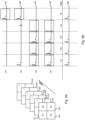
- Fig. 4A shows five video frames 421 ... 422 ... 423 ... 424 ... 425 ... 426, taken at subsequent time moments by a lens similar to lens 301 in Fig. 3 .
- Each video frame 421 is subdivided in four quadrants or sub-regions 431, 432, 433 and 434 respectively corresponding to sub-regions R1, R2, R3 and R4 of the lens.
- a first PPG signal 401 is obtained from the pixels of the first sub-region, 431 or R1.
- the respective segments S1, S2, S3, S4 and S5 of this PPG signal 401 are obtained respectively from the first quadrant pixels in the video frames 421 ... 422 (excluding 422), 422 ... 423 (excluding 423), 423 ...
- a second PPG signal 402 is obtained from the pixels of the second sub-region, 432 or R2.
- the respective segments S1, S2, S3, S4 and S5 of this PPG signal 402 are obtained respectively from the second quadrant pixels in the video frames 421 ... 422 (excluding 422), 422 ... 423 (excluding 423), 423 ... 424 (excluding 424), 424 ... 425 (excluding 425) and 425 ... 426 (excluding 426).
- a third PPG signal 403 is obtained from the pixels of the third sub-region.
- the respective segments S1, S2, S3, S4 and S5 of this PPG signal 403 are obtained respectively from the third quadrant pixels in the video frames 421 ... 422 (excluding 422), 422 ... 423 (excluding 423), 423 ... 424 (excluding 424), 424 ... 425 (excluding 425) and 425 ... 426 (excluding 426).
- a fourth PPG signal 404 is obtained from the pixels of the fourth sub-region, 434 or R4.
- the respective segments S1, S2, S3, S4 and S5 of this PPG signal 404 are obtained respectively from the fourth quadrant pixels in the video frames 421 ... 422 (excluding 422), 422 ... 423 (excluding 423), 423 ... 424 (excluding 424), 424 ...
- a quality assessment is performed for the entire sub-region PPG signals 401, 402, 403 and 404. It is further assumed that the quality assessment reveals that sub-region PPG signals 401 and 402 are of bad quality, whereas sub-region PPG signals 403 and 404 are of good quality. Consequently, the sub-region PPG signals 403 and 404 are combined statically into multi-region PPG signal 405, e.g. through an averaged sum of these signals. The bad quality sub-region PPG signals 401 and 402 are removed and thus not used in the composition of the multi-region PPG signal 405. In the static multi-region PPG embodiment, illustrated by Fig.
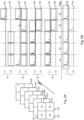
- FIG. 5A shows video frames 521 ... 522 ... 523 ... 524 ... 525 ... 526, taken at subsequent time moments by a lens similar to lens 301 in Fig. 3 .
- Each video frame 521 is subdivided in four quadrants or sub-regions 531, 532, 533 and 534 respectively corresponding to sub-regions R1, R2, R3 and R4 of the lens.
- a first PPG signal 501 is obtained from the pixels of the first sub-region, 531 or R1.
- the respective segments S1, S2, S3, S4 and S5 of this PPG signal 501 are obtained respectively from the first quadrant pixels in the video frames 521 ... 522 (excluding 522), 522 ...
- a second PPG signal 502 is obtained from the pixels of the second sub-region, 532 or R2.
- the respective segments S1, S2, S3, S4 and S5 of this PPG signal 502 are obtained respectively from the second quadrant pixels in the video frames 521 ... 522 (excluding 522), 522 ... 523 (excluding 523), 523 ... 524 (excluding 524), 524 ... 525 (excluding 525) and 525 ... 526 (excluding 526).
- a third PPG signal 503 is obtained from the pixels of the third sub-region.
- the respective segments S1, S2, S3, S4 and S5 of this PPG signal 503 are obtained respectively from the third quadrant pixels in the video frames 521 ... 522 (excluding 522), 522 ... 523 (excluding 523), 523 ... 524 (excluding 524), 524 ... 525 (excluding 525) and 525 ... 526 (excluding 526).
- a fourth PPG signal 504 is obtained from the pixels of the fourth sub-region, 534 or R4.
- the respective segments S1, S2, S3, S4 and S5 of this PPG signal 504 are obtained respectively from the fourth quadrant pixels in the video frames 521 ... 522 (excluding 522), 522 ... 523 (excluding 523), 523 ... 524 (excluding 524), 524 ...
- a quality assessment is performed for the individual segments S1, S2, S3, S4 and S5 of each of the sub-region PPG signals 501, 502, 503 and 504. It is further assumed that the quality assessment reveals that segments S1, S2, S3 and S4 of sub-region PPG signals 503 and 504 are of good quality, and segments S5 of sub-region signals PPG signals 501 and 502 are of good quality. All other segments are supposed to be of bad quality. Consequently, the good quality segments of the sub-region PPG signals 501, 502, 503 and 504 are dynamically combined to compose multi-region PPG signal 505.
- the segments S1 of sub-region PPG signals 503 and 504 are combined into segment S1 of multi-region PPG signal 505, e.g. through an averaged sum of these signals.
- the segments S2 of sub-region PPG signals 503 and 504 are combined into segment S2 of multi-region PPG signal 505
- the segments S3 of sub-region PPG signals 503 and 504 are combined into segment S3 of multi-region PPG signal 505
- the segments S4 of sub-region PPG signals 503 and 504 are combined into segment S4 of multi-region PPG signal 505
- the segments S5 of sub-region PPG signals 501 and 502 are combined into segment S5 of multi-region PPG signal 505.
- the bad quality segments of sub-region PPG signals 501, 502, 503 and 504 are removed and thus not used in the composition of the multi-region PPG signal 505.
- the dynamic multi-region PPG embodiment illustrated by Fig. 5A and Fig. 5B is more processing intensive than the static multi-region PPG composition illustrated by Fig. 4A and Fig. 4B , but brings the advantage that all good quality segments of all sub-region PPG signals are used in order to generate a multi-region PPG signal 505 with enhanced accuracy and reliability.
- multi-region PPG signal 505 for instance contains the additional peak in segment S5, as a result of using the good quality segments S5 of PPG signals 501 and 502.
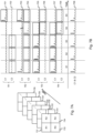
- FIG. 6A shows video frames 621 ... 622 ... 623 ... 624 ... 625 ... 626, taken at subsequent time moments by a lens similar to lens 301 in Fig. 3 .
- Each video frame 621 is subdivided in four quadrants or sub-regions 631, 632, 633 and 634 respectively corresponding to sub-regions R1, R2, R3 and R4 of the lens, and for each of these quadrants 631, 632, 633 and 634 pixels of a first color C1 and pixels of a second color C2 are obtained.
- a first PPG signal 601 is obtained and from the C2 pixels of the first sub-region, 631 or R1, a second PPG signal 602 is obtained.
- the respective segments S1, S2, S3, S4 and S5 of these PPG signals 601 and 602 are obtained respectively from the first quadrant C1 and C2 pixels in the video frames 621 ... 622 (excluding 622), 622 ... 623 (excluding 623), 623 ... 624 (excluding 624), 624 ... 625 (excluding 625) and 625 ... 626 (excluding 626).
- a third PPG signal 603 is obtained from the C1 pixels of the second sub-region, 632 or R2.
- a fourth PPG signal 604 is obtained from the C2 pixels of the second sub-region, 632 or R2.
- the respective segments S1, S2, S3, S4 and S5 of these PPG signals 603 and 604 are obtained respectively from the second quadrant C1 and C2 pixels in the video frames 621 ... 622 (excluding 622), 622 ... 623 (excluding 623), 623 ... 624 (excluding 624), 624 ... 625 (excluding 625) and 625 ... 626 (excluding 626).
- a fifth PPG signal 605 is obtained from the C2 pixels of the third sub-region, 633 or R3, a sixth PPG signal 606 is obtained.
- the respective segments S1, S2, S3, S4 and S5 of these PPG signals 605 and 606 are obtained respectively from the third quadrant C1 and C2 pixels in the video frames 621 ... 622 (excluding 622), 622 ... 623 (excluding 623), 623 ... 624 (excluding 624), 624 ... 625 (excluding 625) and 625 ... 626 (excluding 626).
- a seventh PPG signal 607 is obtained from the C1 pixels of the fourth sub-region, 634 or R4.
- an eight PPG signal 608 is obtained.
- the respective segments S1, S2, S3, S4 and S5 of these PPG signals 607 and 608 are obtained respectively from the fourth quadrant C1 and C2 pixels in the video frames 621 ... 622 (excluding 622), 622 ... 623 (excluding 623), 623 ... 624 (excluding 624), 624 ... 625 (excluding 625) and 625 ... 626 (excluding 626).
- Fig. 6B it is then assumed that a quality assessment is performed for the individual segments S1, S2, S3, S4 and S5 of each of the sub-region PPG signals 601-608.
- the quality assessment reveals that segments S1, S2, S3 and S4 of sub-region PPG signals 605 and 607 are of good quality, and segments S5 of sub-region signals PPG signals 601 and 603 are of good quality. All other segments in the C1 PPG signals 601, 603, 605 and 607 are supposed to be of bad quality. Consequently, the good quality C1 segments of the sub-region PPG signals 601, 603, 605 and 607 are dynamically combined to compose a multi-region PPG signal 609 for the first color C1. The segments S1 of sub-region PPG signals 605 and 607 are combined into segment S1 of multi-region PPG signal 609, e.g. through an averaged sum of these signals.
- the segments S2 of sub-region PPG signals 605 and 607 are combined into segment S2 of multi-region PPG signal 609
- the segments S3 of sub-region PPG signals 605 and 607 are combined into segment S3 of multi-region PPG signal 609
- the segments S4 of sub-region PPG signals 605 and 607 are combined into segment S4 of multi-region PPG signal 609
- the segments S5 of sub-region PPG signals 601 and 603 are combined into segment S5 of multi-region PPG signal 609.
- the bad quality segments of sub-region PPG signals 601, 603, 605 and 607 are removed and thus not used in the composition of the multi-region PPG signal 609 for the first color C1.
- the quality assessment reveals that segments S1, S2 and S3 of sub-region PPG signals 602 and 604 are of good quality, and segments S4 and S5 of sub-region signals PPG signals 604, 606 and 608 are of good quality. All other segments in the C2 PPG signals 602, 604, 606 and 608 are supposed to be of bad quality. Consequently, the good quality C2 segments of the sub-region PPG signals 602, 604, 606 and 608 are dynamically combined to compose a multi-region PPG signal 610 for the second color C2. The segments S1 of sub-region PPG signals 602 and 604 are combined into segment S1 of multi-region PPG signal 610, e.g. through an averaged sum of these signals.
- the segments S2 of sub-region PPG signals 602 and 604 are combined into segment S2 of multi-region PPG signal 610
- the segments S3 of sub-region PPG signals 602 and 604 are combined into segment S3 of multi-region PPG signal 610
- the segments S4 of sub-region PPG signals 604, 606 and 608 are combined into segment S4 of multi-region PPG signal 610
- the segments S5 of sub-region PPG signals 604, 606 and 608 are combined into segment S5 of multi-region PPG signal 610.
- the bad quality segments of sub-region PPG signals 602, 604, 606 and 608 are removed and thus not used in the composition of the multi-region PPG signal 610 for the second color C2.
- a quality assessment is made for the multi-region PPG signals 609 and 610 in order to select the best color, i.e. the color whose multi-region PPG signal has the best quality score according to some quality measure.
- the quality assessment reveals that multi-region PPG signal 609 has a better quality than multi-region PPG signal 610.
- the first color C1 is selected.
- the dynamic multi-region PPG embodiment with color selection illustrated by Fig. 6A and Fig. 6B is even more processing intensive, but brings the advantage that all good quality segments of all sub-region PPG signals are used and this for plural colors.
- the best color is selected in order to optimize the accuracy and reliability of the multi-region PPG signal without requiring the different colors to be synchronized.
- FIG. 7A shows video frames 721 ... 722 ... 723 ... 724 ... 725 ... 726, taken at subsequent time moments by a lens similar to lens 301 in Fig. 3 .
- Each video frame 721 is subdivided in four quadrants or sub-regions 731, 732, 733 and 734 respectively corresponding to sub-regions R1, R2, R3 and R4 of the lens, and for each of these quadrants 731, 732, 733 and 734 pixels of a first color C1 and pixels of a second color C2 are obtained.
- a first PPG signal 701 is obtained and from the C2 pixels of the first sub-region, 731 or R1, a second PPG signal 702 is obtained.
- the respective segments S1, S2, S3, S4 and S5 of these PPG signals 701 and 702 are obtained respectively from the first quadrant C1 and C2 pixels in the video frames 721 ... 722 (excluding 722), 722 ... 723 (excluding 723), 723 ... 724 (excluding 724), 724 ... 725 (excluding 725) and 725 ... 726 (excluding 726).
- a third PPG signal 703 is obtained from the C1 pixels of the second sub-region, 732 or R2.
- a fourth PPG signal 704 is obtained from the C2 pixels of the second sub-region, 732 or R2.
- the respective segments S1, S2, S3, S4 and S5 of these PPG signals 703 and 704 are obtained respectively from the second quadrant C1 and C2 pixels in the video frames 721 ... 722 (excluding 722), 722 ... 723 (excluding 723), 723 ... 724 (excluding 724), 724 ... 725 (excluding 725) and 725 ... 726 (excluding 726).
- a fifth PPG signal 705 is obtained from the C2 pixels of the third sub-region, 733 or R3, a sixth PPG signal 706 is obtained.
- the respective segments S1, S2, S3, S4 and S5 of these PPG signals 705 and 706 are obtained respectively from the third quadrant C1 and C2 pixels in the video frames 721 ... 722 (excluding 722), 722 ... 723 (excluding 723), 723 ... 724 (excluding 724), 724 ... 725 (excluding 725) and 725 ... 726 (excluding 726).
- a seventh PPG signal 707 is obtained from the C1 pixels of the fourth sub-region, 734 or R4.
- an eight PPG signal 708 is obtained.
- the respective segments S1, S2, S3, S4 and S5 of these PPG signals 707 and 708 are obtained respectively from the fourth quadrant C1 and C2 pixels in the video frames 721 ... 722 (excluding 722), 722 ... 723 (excluding 723), 723 ... 724 (excluding 724), 724 ... 725 (excluding 725) and 725 ... 726 (excluding 726).
- Fig. 7B it is then assumed that a quality assessment is performed for the individual segments S1, S2, S3, S4 and S5 of each of the sub-region PPG signals 701-708.
- the quality assessment reveals that segments S1, S2, S3 and S4 of sub-region PPG signals 705 and 707 are of good quality, and segments S5 of sub-region signals PPG signals 701 and 703 are of good quality. All other segments in the C1 PPG signals 701, 703, 705 and 707 are supposed to be of bad quality. It is further assumed that for the second color C2, the quality assessment reveals that segments S1, S2 and S3 of sub-region PPG signals 702 and 704 are of good quality, and segments S4 and S5 of sub-region signals PPG signals 704, 706 and 708 are of good quality. All other segments in the C2 PPG signals 702, 704, 706 and 708 are supposed to be of bad quality.
- the good quality segments of plural colors that are temporarily corresponding and that are supposed to be synchronised are then dynamically combined into a single multi-color multi-region PPG signal 709.
- the segments S1 of sub-region PPG signals 702, 704, 705 and 707 are combined into segment S1 of multi-region PPG signal 709, e.g. through an averaged sum of these signals.
- the segments S2 of sub-region PPG signals 702, 704, 705 and 707 are combined into segment S2 of multi-region PPG signal 709
- the segments S3 of sub-region PPG signals 702, 704, 705 and 707 are combined into segment S3 of multi-region PPG signal 709
- the segments S4 of sub-region PPG signals 704, 705, 706, 707 and 708 are combined into segment S4 of multi-region PPG signal 709
- the segments S5 of sub-region PPG signals 701, 703, 704, 706 and 708 are combined into segment S5 of multi-region PPG signal 709.
- the bad quality segments of sub-region PPG signals 701-708 are removed and thus not used in the composition of the multi-region PPG signal 709.
- the dynamic multi-color multi-region PPG embodiment illustrated by Fig. 7A and Fig. 7B is even more processing intensive and requires synchronization between the colors C1 and C2, but it brings the advantage that all good quality segments of all sub-region PPG signals and all colors are combined. This way, a PPG signal 709 is composed with optimal accuracy and reliability.
- the multi-color multi-region PPG signal 709 obtained through dynamic combination of regions and colors also contains the peak in segment S4, whereas this peak remains absent in the multi-region PPG signal 609 obtained through dynamic combination of regions with color selection.
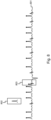
- Fig. 8 illustrates a possible implementation of the peak detection step 106 in Fig. 1 .
- peaks are detected, e.g. by comparing the signal strength with the average signal strength.
- Detected peaks in multi-region PPG signal 801 are marked with a dot.
- These peaks are then windowed and the windowed peaks are averaged to generate a peak template 802, i.e. a model peak.
- each detected peak is correlated with the peak template 802. Peaks for which the correlation exceeds a certain correlation threshold are maintained. Peaks for which the correlation stays below the correlation threshold, like for instance 803 in Fig. 8 , are removed.
- the steps of averaging to generate a peak template, correlating to identify peaks that are kept and peaks that are dropped are iteratively repeated until a stable situation is reached wherein no peaks are dropped anymore.
- Fig. 9 illustrates a possible implementation of the RR-tachogram extraction step 107 in Fig. 1 .
- the RR-tachogram 900 has the time as horizontal axis and the time difference between subsequent peaks in the multi-region PPG signal as vertical axis.
- the RR-tachogram shows the variability in the peak rate, i.e. the variability in the heartrate in case the peaks in the multi-region PPG signal represent heart pulses of a monitored person.
- the reliability of the extracted RR-tachogram may be improved by performing a quality analysis of the multi-region PPG signal. This quality analysis may be done using a quality assessment technique similar to the one described here above, i.e.
- RR-intervals that are located entirely or partially within a bad quality portion of the multi-region PPG signal, like 901, 902, 903 and 904 in Fig. 9 . This way, a processed, more reliable RR-tachogram is obtained. From the RR-tachogram, the variability in the peak rate can be determined. If this variability exceeds certain thresholds, corresponding atrial fibrillation risk score values may be reported to the monitored person or his physician.
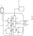
- Fig. 10 shows a suitable computing system 1000 as used in an embodiment of the invention.
- Computing system 1000 is suitable for implementing steps of the method for contact PPG in according with the present invention.
- Computing system 1000 may in general be formed as a suitable general-purpose computer and comprise a bus 1010, a processor 1002, a local memory 1004, one or more optional input interfaces 1014, one or more optional output interfaces 1016, a communication interface 1012, a storage element interface 1006 and one or more storage elements 1008.
- Bus 1010 may comprise one or more conductors that permit communication among the components of the computing system 1000.
- Processor 1002 may include any type of conventional processor or microprocessor that interprets and executes programming instructions.
- Local memory 1004 may include a random access memory (RAM) or another type of dynamic storage device that stores information and instructions for execution by processor 1002 and/or a read only memory (ROM) or another type of static storage device that stores static information and instructions for use by processor 1002.
- RAM random access memory
- ROM read only memory
- Input interface 1014 may comprise one or more conventional mechanisms that permit an operator or user to input information to the computing device 1000, such as a keyboard 1020, a mouse 1030, a pen, voice recognition and/or biometric mechanisms, a camera, etc.
- Output interface 1016 may comprise one or more conventional mechanisms that output information to the operator or user, such as a display 1040, etc.
- Communication interface 1012 may comprise any transceiver-like mechanism such as for example one or more Ethernet interfaces that enables computing system 1000 to communicate with other devices and/or systems, for example with other computing devices 1081, 1082, 1083.
- the communication interface 1012 of computing system 1000 may be connected to such another computing system by means of a local area network (LAN) or a wide area network (WAN) such as for example the internet.
- Storage element interface 1006 may comprise a storage interface such as for example a Serial Advanced Technology Attachment (SATA) interface or a Small Computer System Interface (SCSI) for connecting bus 1010 to one or more storage elements 1008, such as one or more local disks, for example SATA disk drives, and control the reading and writing of data to and/or from these storage elements 1008.
- SATA Serial Advanced Technology Attachment
- SCSI Small Computer System Interface
- the storage elements 1008 above is described as a local disk, in general any other suitable computer-readable media such as a removable magnetic disk, optical storage media such as a CD or DVD, -ROM disk, solid state drives, flash memory cards, ... could be used. It is noticed that the method according to the present invention can be partially executed on a remote electronic device, e.g. worn by the user, and partially on a central server. Computing system 1000 could thus correspond to the processing system available centrally or the processing system available in the electronic device.
- top, bottom, over, under, and the like are introduced for descriptive purposes and not necessarily to denote relative positions. It is to be understood that the terms so used are interchangeable under appropriate circumstances and embodiments of the invention are capable of operating according to the present invention in other sequences, or in orientations different from the one(s) described or illustrated above.
Claims (13)
- Computerimplementiertes Verfahren (100) für Kontakt-Photoplethysmographie, abgekürzt Kontakt-PPG, umfassend:- während eines Zeitintervalls, Erhalten (101) mehrerer PPG-Signale (311-314; 401-404; 501-504; 601-608; 701-708) für jeweilige Unterregionen (321-324; 431-434; 531-534; 631-634; 731-734) eines Objektivs (301) oder Videorahmens, wobei jede Unterregion der Unterregionen (321-324; 431-434; 531-534; 631-634; 731-734) mehrere Pixel abdeckt,DADURCH GEKENNZEICHNET, DASS das Verfahren ferner Folgendes umfasst:- Beurteilen der Qualität (141) der PPG-Signale (311-314; 401-404; 501-504; 601-608; 701-708) oder von Abschnitten davon und Erfassen einer Inversion (142) der PPG-Signale oder von Abschnitten davon;- Zurücksetzen von Abschnitten der PPG-Signale (311-314; 401-404; 501-504; 601-608; 701-708), die invertiert sind;- Entfernen von Abschnitten schlechter Qualität aus den PPG-Signalen (311-314; 401-404; 501-504; 601-608; 701-708); und- Kombinieren (105) der mehreren PPG-Signale (311-314; 401-404; 501-504; 601-608; 701-708), um dadurch ein Mehrregionen-PPG-Signal (405; 505; 609; 709) zu erhalten, wobei Abschnitte guter Qualität der mehreren PPG-Signale kombiniert werden.
- Computerimplementiertes Verfahren (100) für Kontakt-PPG nach Anspruch 1, ferner umfassend:- Segmentieren der PPG-Signale (311-314; 401-404; 501-504; 601-608; 701-708) in Zeitsegmente entsprechend den Abschnitten, wobei die Segmentierung für alle PPG-Signale identisch ist, sodass für jedes Segment in einem PPG-Signal zeitlich entsprechende Segmente in den PPG-Signalen vorhanden sind, die für andere Unterregionen erhalten werden;- und wobei das Kombinieren (105) der mehreren PPG-Signale (311-314; 401-404; 501-504; 601-608; 701-708) Kombinieren zeitlich entsprechender Segmente guter Qualität der mehreren PPG-Signale (321-324; 431-434; 531-534; 631-634; 731-734) umfasst, um das Mehrregionen-PPG-Signal (405; 505; 609; 709) zu erhalten.
- Computerimplementiertes Verfahren (100) für Kontakt-PPG nach Anspruch 2, wobei das Verarbeiten (104) jedes PPG-Signals (201) Folgendes umfasst:- Wavelet-Transformieren des PPG-Signals (201), um ein Wavelet-transformiertes PPG-Signal (202) zu erhalten, und- Zuführen des Wavelet-transformierten PPG-Signals (202) zu einem neuralen Netz (203), das darauf trainiert ist, Segmente guter Qualität des PPG-Signals und Segmente (241, 242, 243) schlechter Qualität des PPG-Signals (201) zu identifizieren.
- Computerimplementiertes Verfahren (100) für Kontakt-PPG nach Anspruch 3, wobei das neuronale Netz (203) ferner darauf trainiert ist, die invertierten Segmente zu identifizieren.
- Computerimplementiertes Verfahren (100) für Kontakt-PPG nach einem der vorhergehenden Ansprüche, umfassend:- Generieren mehrerer Mehrregionen-PPG-Signale (609, 610) ähnlich dem Mehrregionen-PPG-Signal (609) für jeweilige Farben (C1, C2) aus einem Farbraum.
- Computerimplementiertes Verfahren (100) für Kontakt-PPG nach Anspruch 5, ferner umfassend:- Bestimmen eines Qualitätsmaßes für jede der Farben (C1, C2); und- Auswählen des Mehrregionen-PPG-Signals (609) aus den mehreren Mehrregionen-PPG-Signalen (609, 610) für die Farbe (C1) mit dem höchsten Qualitätsmaß.
- Computerimplementiertes Verfahren (100) für Kontakt-PPG nach Anspruch 5, ferner umfassend:- Bestimmen eines Qualitätsmaßes für jede der Farben (C1, C2); und- Kombinieren von Mehrregionen-PPG-Signalen für mehrere Farben zu einem Mehrfarben-Mehrregionen-PPG-Signal.
- Computerimplementiertes Verfahren (100) für Kontakt-PPG nach Anspruch 7, ferner umfassend:- Erhalten mehrerer PPG-Signale (701, 703, 705, 707; 702, 704, 706, 708) während des Zeitintervalls für jeweilige Farben (C1, C2) und jeweilige Unterregionen (731, 732, 733, 734);- Verarbeiten jedes PPG-Signals der mehreren PPG-Signale (701-708), um Segmente guter Qualität des PPG-Signals zu identifizieren, wobei ein Qualitätsmaß des PPG-Signals über einer Schwelle und Segmenten schlechter Qualität des PPG-Signals liegt, wobei das Qualitätsmaß des PPG-Signals unter der Schwelle liegt,- Entfernen der Segmente schlechter Qualität aus jedem PPG-Signal der mehreren PPG-Signale (701-708); und- Kombinieren zeitlich entsprechender Segmente guter Qualität der mehreren PPG-Signale (701-708), um das Mehrfarben-Mehrregionen-PPG-Signal (709) zu erhalten.
- Computerimplementiertes Verfahren (100) für Kontakt-PPG nach einem der vorhergehenden Ansprüche, ferner umfassend Sperren von Einstellungen des Objektivs (301) während des Zeitintervalls, wobei die Einstellungen mindestens Folgendes umfassen:- Blende; und- Lichtempfindlichkeit oder Belichtung.
- Computerimplementiertes Verfahren (100) für Kontakt-PPG nach einem der vorangehenden Ansprüche, ferner umfassend Erfassen (106) von Spitzen in dem Mehrregionen-PPG-Signal (801) und dazu:- Erfassen von Anfangsspitzen in dem Mehrregionen-PPG-Signal (801);- Fenstern der Anfangsspitzen in dem Mehrregionen-PPG-Signal (801), um dadurch gefensterte Anfangsspitzen zu generieren;- Mitteln der gefensterten Anfangsspitzen in dem Mehrregionen-PPG-Signal (801), um dadurch eine Spitzenschablone (802) zu generieren;- Korrelieren der Anfangsspitzen mit der Spitzenschablone (802);- Aufrechterhalten von Anfangsspitzen, für die ein Korrelationsmaß eine Korrelationsschwelle als Spitzen überschreitet; und- Absenken von Anfangsspitzen, für die das Korrelationsmaß die Korrelationsschwelle nicht überschreitet.
- Computerimplementiertes Verfahren (100) für Kontakt-PPG nach Anspruch 10, ferner umfassend:- Extrahieren (107) eines RR-Tachogramms (900) durch Bestimmen einer Zeitdifferenz zwischen aufeinanderfolgenden Spitzen in dem Mehrregionen-PPG-Signal (801).
- Computerimplementiertes Verfahren (100) für Kontakt-PPG nach Anspruch 11, ferner umfassend:- Verarbeiten des Mehrregionen-PPG-Signals (801), um Segmente guter Qualität des Mehrregionen-PPG-Signals (801) zu identifizieren, wobei ein Qualitätsmaß des Mehrregionen-PPG-Signals (801) über einer Schwelle und Segmenten schlechter Qualität des Mehrregionen-PPG-Signal (801) liegt, wobei das Qualitätsmaß des Mehrregionen-PPG-Signals unter der Schwelle liegt,- Entfernen von Spitzen innerhalb der Segmente schlechter Qualität aus dem Mehrregionen-PPG-Signal (801) vor dem Extrahieren des RR-Tachogramms (900); und- Entfernen der RR-Tachogramm-Intervalle aus dem RR-Tachogramm, die sich ganz oder teilweise innerhalb der Segmente schlechter Qualität des Mehrregionen-PPG-Signals (801) befinden.
- System zur Kontakt-Photoplethysmographie, abgekürzt Kontakt-PPG, umfassend:- eine Kamera zum Erhalten (101) mehrerer PPG-Signale (311-314; 401-404; 501-504; 601-608; 701-708) für jeweilige Unterregionen (321-324; 431-434; 531-534; 631-634; 731-734) eines Objektivs (301) oder Videorahmens während eines Zeitintervalls, wobei jede Unterregion der Unterregionen (321-324; 431-434; 531-534; 631-634; 731-734) mehrere Pixel abdeckt,DADURCH GEKENNZEICHNET, DASS das System ferner ein Datenverarbeitungssystem umfasst, das unter der Steuerung eines Computerprogramms dazu programmiert ist, Folgendes durchzuführen:- Beurteilen der Qualität der PPG-Signale (311-314; 401-404; 501-504; 601-608; 701-708) oder von Abschnitten davon und Erfassen einer Inversion der PPG-Signale oder von Abschnitten davon;- Zurücksetzen von Abschnitten der PPG-Signale (311-314; 401-404; 501-504; 601-608; 701-708), die invertiert sind;- Entfernen von Abschnitten schlechter Qualität aus den PPG-Signalen (311-314; 401-404; 501-504; 601-608; 701-708); und- Kombinieren (105) der mehreren PPG-Signale (311-314; 401-404; 501-504; 601-608; 701-708), um dadurch ein Mehrregionen-PPG-Signal (405; 505; 609; 709) zu erhalten, wobei Abschnitte guter Qualität der mehreren PPG-Signale kombiniert werden.
Priority Applications (4)
| Application Number | Priority Date | Filing Date | Title |
|---|---|---|---|
| EP17188626.0A EP3449820B1 (de) | 2017-08-30 | 2017-08-30 | Computerimplementiertes verfahren und system für direkte photoplethysomografie |
| CN201880056100.2A CN111050638B (zh) | 2017-08-30 | 2018-08-10 | 用于接触式光学体积描记术(ppg)的计算机实现的方法和系统 |
| PCT/EP2018/071728 WO2019042739A1 (en) | 2017-08-30 | 2018-08-10 | COMPUTER-IMPLEMENTED METHOD AND SYSTEM FOR PHOTOPLETHYSMOGRAPHY (PPG) BY CONTACT |
| US16/640,221 US11583198B2 (en) | 2017-08-30 | 2018-08-10 | Computer-implemented method and system for contact photoplethysmography (PPG) |
Applications Claiming Priority (1)
| Application Number | Priority Date | Filing Date | Title |
|---|---|---|---|
| EP17188626.0A EP3449820B1 (de) | 2017-08-30 | 2017-08-30 | Computerimplementiertes verfahren und system für direkte photoplethysomografie |
Publications (2)
| Publication Number | Publication Date |
|---|---|
| EP3449820A1 EP3449820A1 (de) | 2019-03-06 |
| EP3449820B1 true EP3449820B1 (de) | 2023-05-24 |
Family
ID=59856367
Family Applications (1)
| Application Number | Title | Priority Date | Filing Date |
|---|---|---|---|
| EP17188626.0A Active EP3449820B1 (de) | 2017-08-30 | 2017-08-30 | Computerimplementiertes verfahren und system für direkte photoplethysomografie |
Country Status (4)
| Country | Link |
|---|---|
| US (1) | US11583198B2 (de) |
| EP (1) | EP3449820B1 (de) |
| CN (1) | CN111050638B (de) |
| WO (1) | WO2019042739A1 (de) |
Families Citing this family (3)
| Publication number | Priority date | Publication date | Assignee | Title |
|---|---|---|---|---|
| EP3473173B1 (de) * | 2017-10-19 | 2024-04-03 | Qompium | Computerimplementiertes verfahren und system zur direkten photoplethysmographie (ppg) mit mehreren sensoren |
| CN114081502B (zh) * | 2021-11-11 | 2022-09-27 | 中国科学院深圳先进技术研究院 | 一种基于机器学习的非侵入性心脏病诊断方法和装置 |
| EP4201317A1 (de) | 2021-12-22 | 2023-06-28 | Qompium | Ppg-signalverarbeitungsvorrichtung und entsprechendes computerimplementiertes verfahren |
Family Cites Families (22)
| Publication number | Priority date | Publication date | Assignee | Title |
|---|---|---|---|---|
| US20090203998A1 (en) * | 2008-02-13 | 2009-08-13 | Gunnar Klinghult | Heart rate counter, portable apparatus, method, and computer program for heart rate counting |
| US8532932B2 (en) * | 2008-06-30 | 2013-09-10 | Nellcor Puritan Bennett Ireland | Consistent signal selection by signal segment selection techniques |
| US8636667B2 (en) * | 2009-07-06 | 2014-01-28 | Nellcor Puritan Bennett Ireland | Systems and methods for processing physiological signals in wavelet space |
| US20110077484A1 (en) | 2009-09-30 | 2011-03-31 | Nellcor Puritan Bennett Ireland | Systems And Methods For Identifying Non-Corrupted Signal Segments For Use In Determining Physiological Parameters |
| RU2612386C2 (ru) | 2011-01-05 | 2017-03-09 | Конинклейке Филипс Электроникс Н.В. | Устройства и способы видеокодирования и декодирования с сохранением относящейся к ppg информации |
| US10548490B2 (en) * | 2012-03-01 | 2020-02-04 | Pixart Imaging Inc. | Physiological detection device and operating method thereof |
| US8977347B2 (en) * | 2012-06-25 | 2015-03-10 | Xerox Corporation | Video-based estimation of heart rate variability |
| WO2014024104A1 (en) | 2012-08-06 | 2014-02-13 | Koninklijke Philips N.V. | Device and method for extracting physiological information |
| US9433386B2 (en) * | 2013-07-09 | 2016-09-06 | Xerox Corporation | Method and apparatus for monitoring a subject for atrial fibrillation |
| CN105792734B (zh) | 2013-10-01 | 2018-11-27 | 皇家飞利浦有限公司 | 用于获得远程光体积描记波形的改进的信号选择 |
| KR20150067047A (ko) * | 2013-12-09 | 2015-06-17 | 삼성전자주식회사 | 모듈러 센서 플랫폼 |
| RU2684044C1 (ru) * | 2013-12-12 | 2019-04-03 | Конинклейке Филипс Н.В. | Устройство и способ для определения основных показателей жизнедеятельности субъекта |
| US10028669B2 (en) * | 2014-04-02 | 2018-07-24 | Massachusetts Institute Of Technology | Methods and apparatus for physiological measurement using color band photoplethysmographic sensor |
| WO2015180986A1 (en) * | 2014-05-28 | 2015-12-03 | Koninklijke Philips N.V. | Motion artifact reduction using multi-channel ppg signals |
| US9737219B2 (en) * | 2014-05-30 | 2017-08-22 | Mediatek Inc. | Method and associated controller for life sign monitoring |
| US9955880B2 (en) * | 2014-10-27 | 2018-05-01 | Tata Consultancy Services Limited | Estimating physiological parameters |
| KR20170008043A (ko) | 2015-07-13 | 2017-01-23 | 엘지전자 주식회사 | 이동 단말기의 심박/스트레스 측정회로 및 그 측정 방법 |
| WO2017025775A1 (en) * | 2015-08-11 | 2017-02-16 | Latvijas Universitate | Device for adaptive photoplethysmography imaging |
| US10893814B2 (en) * | 2015-10-06 | 2021-01-19 | Koninklijke Philips N.V. | System and method for obtaining vital sign related information of a living being |
| CA2958003C (en) * | 2016-02-19 | 2022-04-05 | Paul Stanley Addison | System and methods for video-based monitoring of vital signs |
| CN108778109B (zh) * | 2016-03-01 | 2022-02-11 | 皇家飞利浦有限公司 | 用于确定对象的生命体征的设备、系统和方法 |
| US11690513B2 (en) * | 2017-02-13 | 2023-07-04 | Massachusetts Institute Of Technology | Methods and system for multi-channel bio-optical sensing |
-
2017
- 2017-08-30 EP EP17188626.0A patent/EP3449820B1/de active Active
-
2018
- 2018-08-10 CN CN201880056100.2A patent/CN111050638B/zh active Active
- 2018-08-10 WO PCT/EP2018/071728 patent/WO2019042739A1/en active Application Filing
- 2018-08-10 US US16/640,221 patent/US11583198B2/en active Active
Also Published As
| Publication number | Publication date |
|---|---|
| WO2019042739A1 (en) | 2019-03-07 |
| CN111050638A (zh) | 2020-04-21 |
| EP3449820A1 (de) | 2019-03-06 |
| US11583198B2 (en) | 2023-02-21 |
| CN111050638B (zh) | 2023-07-25 |
| US20200359922A1 (en) | 2020-11-19 |
Similar Documents
| Publication | Publication Date | Title |
|---|---|---|
| Bobbia et al. | Unsupervised skin tissue segmentation for remote photoplethysmography | |
| Li et al. | The obf database: A large face video database for remote physiological signal measurement and atrial fibrillation detection | |
| US11229372B2 (en) | Systems and methods for computer monitoring of remote photoplethysmography based on chromaticity in a converted color space | |
| McDuff et al. | Remote detection of photoplethysmographic systolic and diastolic peaks using a digital camera | |
| US10398327B2 (en) | Non-contact assessment of cardiovascular function using a multi-camera array | |
| EP3440991A1 (de) | Vorrichtung, system und verfahren zur bestimmung eines physiologischen parameters eines subjekts | |
| Feng et al. | Motion artifacts suppression for remote imaging photoplethysmography | |
| EP3440996A1 (de) | Vorrichtung, system und verfahren zur bestimmung eines physiologischen parameters eines subjekts | |
| Gudi et al. | Efficient real-time camera based estimation of heart rate and its variability | |
| US11583198B2 (en) | Computer-implemented method and system for contact photoplethysmography (PPG) | |
| US11701015B2 (en) | Computer-implemented method and system for direct photoplethysmography (PPG) with multiple sensors | |
| CN111345803B (zh) | 一种基于移动设备摄像头的心率变异性测量方法 | |
| US11783483B2 (en) | Detecting abnormalities in vital signs of subjects of videos | |
| Shoushan et al. | Non-contact HR monitoring via smartphone and webcam during different respiratory maneuvers and body movements | |
| Sarkar et al. | Evaluation of video magnification for nonintrusive heart rate measurement | |
| Ben Salah et al. | Contactless heart rate estimation from facial video using skin detection and multi-resolution analysis | |
| Yang et al. | cbPPGGAN: A generic enhancement framework for unpaired pulse waveforms in camera-based photoplethysmography | |
| CN113361480B (zh) | 基于人脸视频的人体脉搏波获取方法 | |
| Tan et al. | Camera-based Cardiovascular Screening based on Heart Rate and Its Variability In Pre-and Post-Exercise Conditions | |
| US20240041334A1 (en) | Systems and methods for measuring physiologic vital signs and biomarkers using optical data | |
| Lima et al. | Remote detection of heart beat and heart rate from video sequences | |
| CN116327155A (zh) | 基于自适应roi选择的远程心率测量方法、装置及设备 | |
| Talukdar et al. | The Evaluation of Remote Monitoring Technology Across Participants With Different Skin Tones | |
| Huang et al. | Deep learning-based robust heart rate estimation using remote photoplethysmography under different illuminations | |
| Talukdar et al. | Evaluation of Remote Monitoring Technology across different skin tone participants |
Legal Events
| Date | Code | Title | Description |
|---|---|---|---|
| PUAI | Public reference made under article 153(3) epc to a published international application that has entered the european phase |
Free format text: ORIGINAL CODE: 0009012 |
|
| STAA | Information on the status of an ep patent application or granted ep patent |
Free format text: STATUS: THE APPLICATION HAS BEEN PUBLISHED |
|
| AK | Designated contracting states |
Kind code of ref document: A1 Designated state(s): AL AT BE BG CH CY CZ DE DK EE ES FI FR GB GR HR HU IE IS IT LI LT LU LV MC MK MT NL NO PL PT RO RS SE SI SK SM TR |
|
| AX | Request for extension of the european patent |
Extension state: BA ME |
|
| STAA | Information on the status of an ep patent application or granted ep patent |
Free format text: STATUS: REQUEST FOR EXAMINATION WAS MADE |
|
| 17P | Request for examination filed |
Effective date: 20190906 |
|
| RBV | Designated contracting states (corrected) |
Designated state(s): AL AT BE BG CH CY CZ DE DK EE ES FI FR GB GR HR HU IE IS IT LI LT LU LV MC MK MT NL NO PL PT RO RS SE SI SK SM TR |
|
| RAP1 | Party data changed (applicant data changed or rights of an application transferred) |
Owner name: QOMPIUM |
|
| STAA | Information on the status of an ep patent application or granted ep patent |
Free format text: STATUS: EXAMINATION IS IN PROGRESS |
|
| 17Q | First examination report despatched |
Effective date: 20210730 |
|
| STAA | Information on the status of an ep patent application or granted ep patent |
Free format text: STATUS: EXAMINATION IS IN PROGRESS |
|
| GRAP | Despatch of communication of intention to grant a patent |
Free format text: ORIGINAL CODE: EPIDOSNIGR1 |
|
| STAA | Information on the status of an ep patent application or granted ep patent |
Free format text: STATUS: GRANT OF PATENT IS INTENDED |
|
| INTG | Intention to grant announced |
Effective date: 20230102 |
|
| GRAS | Grant fee paid |
Free format text: ORIGINAL CODE: EPIDOSNIGR3 |
|
| GRAA | (expected) grant |
Free format text: ORIGINAL CODE: 0009210 |
|
| STAA | Information on the status of an ep patent application or granted ep patent |
Free format text: STATUS: THE PATENT HAS BEEN GRANTED |
|
| AK | Designated contracting states |
Kind code of ref document: B1 Designated state(s): AL AT BE BG CH CY CZ DE DK EE ES FI FR GB GR HR HU IE IS IT LI LT LU LV MC MK MT NL NO PL PT RO RS SE SI SK SM TR |
|
| REG | Reference to a national code |
Ref country code: GB Ref legal event code: FG4D |
|
| REG | Reference to a national code |
Ref country code: CH Ref legal event code: EP |
|
| REG | Reference to a national code |
Ref country code: DE Ref legal event code: R096 Ref document number: 602017068957 Country of ref document: DE |
|
| REG | Reference to a national code |
Ref country code: AT Ref legal event code: REF Ref document number: 1569045 Country of ref document: AT Kind code of ref document: T Effective date: 20230615 |
|
| REG | Reference to a national code |
Ref country code: IE Ref legal event code: FG4D |
|
| REG | Reference to a national code |
Ref country code: NL Ref legal event code: FP |
|
| REG | Reference to a national code |
Ref country code: SE Ref legal event code: TRGR |
|
| REG | Reference to a national code |
Ref country code: LT Ref legal event code: MG9D |
|
| PGFP | Annual fee paid to national office [announced via postgrant information from national office to epo] |
Ref country code: NL Payment date: 20230828 Year of fee payment: 7 |
|
| REG | Reference to a national code |
Ref country code: AT Ref legal event code: MK05 Ref document number: 1569045 Country of ref document: AT Kind code of ref document: T Effective date: 20230524 |
|
| PG25 | Lapsed in a contracting state [announced via postgrant information from national office to epo] |
Ref country code: PT Free format text: LAPSE BECAUSE OF FAILURE TO SUBMIT A TRANSLATION OF THE DESCRIPTION OR TO PAY THE FEE WITHIN THE PRESCRIBED TIME-LIMIT Effective date: 20230925 Ref country code: NO Free format text: LAPSE BECAUSE OF FAILURE TO SUBMIT A TRANSLATION OF THE DESCRIPTION OR TO PAY THE FEE WITHIN THE PRESCRIBED TIME-LIMIT Effective date: 20230824 Ref country code: ES Free format text: LAPSE BECAUSE OF FAILURE TO SUBMIT A TRANSLATION OF THE DESCRIPTION OR TO PAY THE FEE WITHIN THE PRESCRIBED TIME-LIMIT Effective date: 20230524 Ref country code: AT Free format text: LAPSE BECAUSE OF FAILURE TO SUBMIT A TRANSLATION OF THE DESCRIPTION OR TO PAY THE FEE WITHIN THE PRESCRIBED TIME-LIMIT Effective date: 20230524 |
|
| PGFP | Annual fee paid to national office [announced via postgrant information from national office to epo] |
Ref country code: GB Payment date: 20230817 Year of fee payment: 7 |
|
| PG25 | Lapsed in a contracting state [announced via postgrant information from national office to epo] |
Ref country code: RS Free format text: LAPSE BECAUSE OF FAILURE TO SUBMIT A TRANSLATION OF THE DESCRIPTION OR TO PAY THE FEE WITHIN THE PRESCRIBED TIME-LIMIT Effective date: 20230524 Ref country code: PL Free format text: LAPSE BECAUSE OF FAILURE TO SUBMIT A TRANSLATION OF THE DESCRIPTION OR TO PAY THE FEE WITHIN THE PRESCRIBED TIME-LIMIT Effective date: 20230524 Ref country code: LV Free format text: LAPSE BECAUSE OF FAILURE TO SUBMIT A TRANSLATION OF THE DESCRIPTION OR TO PAY THE FEE WITHIN THE PRESCRIBED TIME-LIMIT Effective date: 20230524 Ref country code: LT Free format text: LAPSE BECAUSE OF FAILURE TO SUBMIT A TRANSLATION OF THE DESCRIPTION OR TO PAY THE FEE WITHIN THE PRESCRIBED TIME-LIMIT Effective date: 20230524 Ref country code: IS Free format text: LAPSE BECAUSE OF FAILURE TO SUBMIT A TRANSLATION OF THE DESCRIPTION OR TO PAY THE FEE WITHIN THE PRESCRIBED TIME-LIMIT Effective date: 20230924 Ref country code: HR Free format text: LAPSE BECAUSE OF FAILURE TO SUBMIT A TRANSLATION OF THE DESCRIPTION OR TO PAY THE FEE WITHIN THE PRESCRIBED TIME-LIMIT Effective date: 20230524 Ref country code: GR Free format text: LAPSE BECAUSE OF FAILURE TO SUBMIT A TRANSLATION OF THE DESCRIPTION OR TO PAY THE FEE WITHIN THE PRESCRIBED TIME-LIMIT Effective date: 20230825 |
|
| PGFP | Annual fee paid to national office [announced via postgrant information from national office to epo] |
Ref country code: SE Payment date: 20230815 Year of fee payment: 7 Ref country code: FR Payment date: 20230816 Year of fee payment: 7 Ref country code: DE Payment date: 20230816 Year of fee payment: 7 Ref country code: BE Payment date: 20230814 Year of fee payment: 7 |
|
| PG25 | Lapsed in a contracting state [announced via postgrant information from national office to epo] |
Ref country code: FI Free format text: LAPSE BECAUSE OF FAILURE TO SUBMIT A TRANSLATION OF THE DESCRIPTION OR TO PAY THE FEE WITHIN THE PRESCRIBED TIME-LIMIT Effective date: 20230524 |
|
| PG25 | Lapsed in a contracting state [announced via postgrant information from national office to epo] |
Ref country code: SK Free format text: LAPSE BECAUSE OF FAILURE TO SUBMIT A TRANSLATION OF THE DESCRIPTION OR TO PAY THE FEE WITHIN THE PRESCRIBED TIME-LIMIT Effective date: 20230524 |
|
| PG25 | Lapsed in a contracting state [announced via postgrant information from national office to epo] |
Ref country code: SM Free format text: LAPSE BECAUSE OF FAILURE TO SUBMIT A TRANSLATION OF THE DESCRIPTION OR TO PAY THE FEE WITHIN THE PRESCRIBED TIME-LIMIT Effective date: 20230524 Ref country code: SK Free format text: LAPSE BECAUSE OF FAILURE TO SUBMIT A TRANSLATION OF THE DESCRIPTION OR TO PAY THE FEE WITHIN THE PRESCRIBED TIME-LIMIT Effective date: 20230524 Ref country code: RO Free format text: LAPSE BECAUSE OF FAILURE TO SUBMIT A TRANSLATION OF THE DESCRIPTION OR TO PAY THE FEE WITHIN THE PRESCRIBED TIME-LIMIT Effective date: 20230524 Ref country code: EE Free format text: LAPSE BECAUSE OF FAILURE TO SUBMIT A TRANSLATION OF THE DESCRIPTION OR TO PAY THE FEE WITHIN THE PRESCRIBED TIME-LIMIT Effective date: 20230524 Ref country code: DK Free format text: LAPSE BECAUSE OF FAILURE TO SUBMIT A TRANSLATION OF THE DESCRIPTION OR TO PAY THE FEE WITHIN THE PRESCRIBED TIME-LIMIT Effective date: 20230524 Ref country code: CZ Free format text: LAPSE BECAUSE OF FAILURE TO SUBMIT A TRANSLATION OF THE DESCRIPTION OR TO PAY THE FEE WITHIN THE PRESCRIBED TIME-LIMIT Effective date: 20230524 |
|
| REG | Reference to a national code |
Ref country code: DE Ref legal event code: R097 Ref document number: 602017068957 Country of ref document: DE |
|
| PG25 | Lapsed in a contracting state [announced via postgrant information from national office to epo] |
Ref country code: MC Free format text: LAPSE BECAUSE OF FAILURE TO SUBMIT A TRANSLATION OF THE DESCRIPTION OR TO PAY THE FEE WITHIN THE PRESCRIBED TIME-LIMIT Effective date: 20230524 |
|
| REG | Reference to a national code |
Ref country code: CH Ref legal event code: PL |
|
| PG25 | Lapsed in a contracting state [announced via postgrant information from national office to epo] |
Ref country code: MC Free format text: LAPSE BECAUSE OF FAILURE TO SUBMIT A TRANSLATION OF THE DESCRIPTION OR TO PAY THE FEE WITHIN THE PRESCRIBED TIME-LIMIT Effective date: 20230524 |
|
| PLBE | No opposition filed within time limit |
Free format text: ORIGINAL CODE: 0009261 |
|
| STAA | Information on the status of an ep patent application or granted ep patent |
Free format text: STATUS: NO OPPOSITION FILED WITHIN TIME LIMIT |
|
| PG25 | Lapsed in a contracting state [announced via postgrant information from national office to epo] |
Ref country code: LU Free format text: LAPSE BECAUSE OF NON-PAYMENT OF DUE FEES Effective date: 20230830 |