EP3449106B1 - Inside-out rotating coalescer with gas exit through hollow shaft - Google Patents
Inside-out rotating coalescer with gas exit through hollow shaft Download PDFInfo
- Publication number
- EP3449106B1 EP3449106B1 EP17790235.0A EP17790235A EP3449106B1 EP 3449106 B1 EP3449106 B1 EP 3449106B1 EP 17790235 A EP17790235 A EP 17790235A EP 3449106 B1 EP3449106 B1 EP 3449106B1
- Authority
- EP
- European Patent Office
- Prior art keywords
- housing
- filter media
- hollow shaft
- rotating coalescer
- crankcase
- Prior art date
- Legal status (The legal status is an assumption and is not a legal conclusion. Google has not performed a legal analysis and makes no representation as to the accuracy of the status listed.)
- Active
Links
Images




Classifications
-
- F—MECHANICAL ENGINEERING; LIGHTING; HEATING; WEAPONS; BLASTING
- F01—MACHINES OR ENGINES IN GENERAL; ENGINE PLANTS IN GENERAL; STEAM ENGINES
- F01M—LUBRICATING OF MACHINES OR ENGINES IN GENERAL; LUBRICATING INTERNAL COMBUSTION ENGINES; CRANKCASE VENTILATING
- F01M13/00—Crankcase ventilating or breathing
- F01M13/04—Crankcase ventilating or breathing having means for purifying air before leaving crankcase, e.g. removing oil
-
- B—PERFORMING OPERATIONS; TRANSPORTING
- B01—PHYSICAL OR CHEMICAL PROCESSES OR APPARATUS IN GENERAL
- B01D—SEPARATION
- B01D45/00—Separating dispersed particles from gases or vapours by gravity, inertia, or centrifugal forces
- B01D45/12—Separating dispersed particles from gases or vapours by gravity, inertia, or centrifugal forces by centrifugal forces
- B01D45/14—Separating dispersed particles from gases or vapours by gravity, inertia, or centrifugal forces by centrifugal forces generated by rotating vanes, discs, drums or brushes
-
- B—PERFORMING OPERATIONS; TRANSPORTING
- B01—PHYSICAL OR CHEMICAL PROCESSES OR APPARATUS IN GENERAL
- B01D—SEPARATION
- B01D46/00—Filters or filtering processes specially modified for separating dispersed particles from gases or vapours
- B01D46/0002—Casings; Housings; Frame constructions
- B01D46/0005—Mounting of filtering elements within casings, housings or frames
-
- B—PERFORMING OPERATIONS; TRANSPORTING
- B01—PHYSICAL OR CHEMICAL PROCESSES OR APPARATUS IN GENERAL
- B01D—SEPARATION
- B01D46/00—Filters or filtering processes specially modified for separating dispersed particles from gases or vapours
- B01D46/0027—Filters or filtering processes specially modified for separating dispersed particles from gases or vapours with additional separating or treating functions
- B01D46/003—Filters or filtering processes specially modified for separating dispersed particles from gases or vapours with additional separating or treating functions including coalescing means for the separation of liquid
- B01D46/0031—Filters or filtering processes specially modified for separating dispersed particles from gases or vapours with additional separating or treating functions including coalescing means for the separation of liquid with collecting, draining means
-
- B—PERFORMING OPERATIONS; TRANSPORTING
- B01—PHYSICAL OR CHEMICAL PROCESSES OR APPARATUS IN GENERAL
- B01D—SEPARATION
- B01D46/00—Filters or filtering processes specially modified for separating dispersed particles from gases or vapours
- B01D46/0052—Filters or filtering processes specially modified for separating dispersed particles from gases or vapours with filtering elements moving during filtering operation
- B01D46/0056—Filters or filtering processes specially modified for separating dispersed particles from gases or vapours with filtering elements moving during filtering operation with rotational movement
-
- B—PERFORMING OPERATIONS; TRANSPORTING
- B01—PHYSICAL OR CHEMICAL PROCESSES OR APPARATUS IN GENERAL
- B01D—SEPARATION
- B01D46/00—Filters or filtering processes specially modified for separating dispersed particles from gases or vapours
- B01D46/24—Particle separators, e.g. dust precipitators, using rigid hollow filter bodies
- B01D46/2403—Particle separators, e.g. dust precipitators, using rigid hollow filter bodies characterised by the physical shape or structure of the filtering element
-
- B—PERFORMING OPERATIONS; TRANSPORTING
- B01—PHYSICAL OR CHEMICAL PROCESSES OR APPARATUS IN GENERAL
- B01D—SEPARATION
- B01D50/00—Combinations of methods or devices for separating particles from gases or vapours
- B01D50/20—Combinations of devices covered by groups B01D45/00 and B01D46/00
-
- B—PERFORMING OPERATIONS; TRANSPORTING
- B04—CENTRIFUGAL APPARATUS OR MACHINES FOR CARRYING-OUT PHYSICAL OR CHEMICAL PROCESSES
- B04B—CENTRIFUGES
- B04B15/00—Other accessories for centrifuges
- B04B15/10—Other accessories for centrifuges for forming a filtering layer in the rotary bowl
-
- B—PERFORMING OPERATIONS; TRANSPORTING
- B04—CENTRIFUGAL APPARATUS OR MACHINES FOR CARRYING-OUT PHYSICAL OR CHEMICAL PROCESSES
- B04B—CENTRIFUGES
- B04B5/00—Other centrifuges
- B04B5/005—Centrifugal separators or filters for fluid circulation systems, e.g. for lubricant oil circulation systems
-
- B—PERFORMING OPERATIONS; TRANSPORTING
- B01—PHYSICAL OR CHEMICAL PROCESSES OR APPARATUS IN GENERAL
- B01D—SEPARATION
- B01D2265/00—Casings, housings or mounting for filters specially adapted for separating dispersed particles from gases or vapours
- B01D2265/02—Non-permanent measures for connecting different parts of the filter
- B01D2265/028—Snap, latch or clip connecting means
-
- B—PERFORMING OPERATIONS; TRANSPORTING
- B01—PHYSICAL OR CHEMICAL PROCESSES OR APPARATUS IN GENERAL
- B01D—SEPARATION
- B01D2271/00—Sealings for filters specially adapted for separating dispersed particles from gases or vapours
- B01D2271/02—Gaskets, sealings
- B01D2271/027—Radial sealings
-
- B—PERFORMING OPERATIONS; TRANSPORTING
- B01—PHYSICAL OR CHEMICAL PROCESSES OR APPARATUS IN GENERAL
- B01D—SEPARATION
- B01D2279/00—Filters adapted for separating dispersed particles from gases or vapours specially modified for specific uses
- B01D2279/35—Filters adapted for separating dispersed particles from gases or vapours specially modified for specific uses for venting arrangements
-
- F—MECHANICAL ENGINEERING; LIGHTING; HEATING; WEAPONS; BLASTING
- F01—MACHINES OR ENGINES IN GENERAL; ENGINE PLANTS IN GENERAL; STEAM ENGINES
- F01M—LUBRICATING OF MACHINES OR ENGINES IN GENERAL; LUBRICATING INTERNAL COMBUSTION ENGINES; CRANKCASE VENTILATING
- F01M13/00—Crankcase ventilating or breathing
- F01M13/04—Crankcase ventilating or breathing having means for purifying air before leaving crankcase, e.g. removing oil
- F01M2013/0422—Separating oil and gas with a centrifuge device
-
- F—MECHANICAL ENGINEERING; LIGHTING; HEATING; WEAPONS; BLASTING
- F01—MACHINES OR ENGINES IN GENERAL; ENGINE PLANTS IN GENERAL; STEAM ENGINES
- F01M—LUBRICATING OF MACHINES OR ENGINES IN GENERAL; LUBRICATING INTERNAL COMBUSTION ENGINES; CRANKCASE VENTILATING
- F01M13/00—Crankcase ventilating or breathing
- F01M13/04—Crankcase ventilating or breathing having means for purifying air before leaving crankcase, e.g. removing oil
- F01M2013/0422—Separating oil and gas with a centrifuge device
- F01M2013/0427—Separating oil and gas with a centrifuge device the centrifuge device having no rotating part, e.g. cyclone
-
- F—MECHANICAL ENGINEERING; LIGHTING; HEATING; WEAPONS; BLASTING
- F01—MACHINES OR ENGINES IN GENERAL; ENGINE PLANTS IN GENERAL; STEAM ENGINES
- F01M—LUBRICATING OF MACHINES OR ENGINES IN GENERAL; LUBRICATING INTERNAL COMBUSTION ENGINES; CRANKCASE VENTILATING
- F01M13/00—Crankcase ventilating or breathing
- F01M13/04—Crankcase ventilating or breathing having means for purifying air before leaving crankcase, e.g. removing oil
- F01M2013/0438—Crankcase ventilating or breathing having means for purifying air before leaving crankcase, e.g. removing oil with a filter
Definitions
- the present application relates to crankcase ventilation systems.
- blowby gases include a mixture of aerosols, oils, and air. If vented directly to the ambient, the blowby gases can potentially harm the environment and/or may be subject to government emissions regulations. Accordingly, the blowby gases are typically routed out of the crankcase via a crankcase ventilation system.
- the crankcase ventilation system may pass the blowby gases through a coalescer (i.e., a coalescing filter element) to remove a majority of the aerosols and oils contained in the blowby gases.
- the coalescer includes filter media. The filtered blowby gases are then either vented to the ambient (in open crankcase ventilation systems) or routed back to the air intake for the internal combustion engine for further combustion (in closed crankcase ventilation systems).
- crankcase ventilation systems utilize rotating coalescers that increase the filter efficiency of the coalescing filter elements by rotating the filter media during filtering.
- rotating filter cartridges the contaminants (e.g., oil droplets suspended and transported by blowby gases) are separated inside the filter media of the filter cartridge through the particle capture mechanisms of inertial impaction, interception, diffusion, and gravitational forces onto the fibers.
- inertial impaction and gravitational forces are enhanced by the additional centrifugal force.
- the rotation of the filter cartridge can create a pumping effect, which reduces the pressure drop through the filtration system.
- Rotating filter cartridges may include fibrous filters as well as centrifugal separation devices.
- many rotating coalescers are configured for outside-in flow through the filter media for ease of integration into engine compartments and crankcases.
- outside-in flow rotating coalescers suffer from high pressure drops and reduced fractional efficiency compared to inside-out flow rotating coalescers.
- US2011180051 discloses an internal combustion engine crankcase ventilation rotating coalescer which includes an annular rotating coalescing filter element, an inlet port supplying blowby gas from the crankcase to the hollow interior of the annular rotating coalescing filter element, and an outlet port delivering cleaned separated air from the exterior of the rotating element.
- the direction of blowby gas is inside-out, radially outwardly from the hollow interior to the exterior.
- US5716423 discloses an inducer with a reduced number of blades, and varying density porous media disks are arranged in a deoiler mounted on a rotating shaft for total free separation of the oil from and air/oil mixture.
- the porous media disks are arranged with the lower density grade coming into contact with the air/oil mixture and proceeds toward the higher density grade.
- the arrangement of the stages of separation, the specially designed oil discharge holes and the flow geometry maximizes oil separation and removal and reduces pressure losses to control the pressure drop of the deoiler.
- FR2933626 discloses a device has a rotor mounted rotatively around an axis and integrating a separation element with a coalescer medium.
- a stator has a liquid e.g. oil, draining channel and a periphery wall around the rotor, where the stator has an outlet for evacuating treated gas.
- the element defines a non-treated gas upstream zone and a treated gas downstream zone, where the zones are defined by an interior surface and an exterior surface, respectively.
- the channel is arranged at a side of the zone for flow of the liquid passed through the medium.
- An independent claim is also included for a method for separating a gas issued from a case of an internal combustion engine.
- One such rotating coalescer includes a housing comprising a first housing section having a blowby gas inlet structured to receive crankcase blowby gases from a crankcase.
- the housing further comprises an oil outlet.
- the rotating coalescer includes an endcap and filter media.
- the filter media is arranged in a cylindrical shape.
- the filter media is coupled to and positioned between the first housing section and the endcap.
- the filter media is structured to filter the crankcase blowby gases passing through the filter media by coalescing and separating oils and aerosols contained in the crankcase blowby gases.
- the rotating coalescer includes a hollow shaft extending through the housing and positioned radially inside of the filter media.
- the hollow shaft forms a blowby gas outlet structured to route filtered crankcase blowby gases out of the housing.
- the rotating coalescer further includes a drive mechanism operatively coupled to the hollow shaft.
- the drive mechanism is structured to rotate the hollow shaft and the housing.
- the method includes rotating the coalescer with a drive mechanism.
- the coalescer comprises a housing, an endcap, a filter media coupled to the housing and the endcap, and a hollow shaft extending through the housing and positioned radially inside of the filter media, and the drive mechanism is operatively connected to the hollow shaft.
- the method further includes receiving crankcase blowby gases from a crankcase through an inlet of the housing of the coalescer.
- the crankcase blowby gases is passed radially through the filter media in an inside-out flow.
- the crankcase blowby gases is filtered through the filter media.
- crankcase blowby gases is passed to the hollow shaft, wherein the filtered crankcase blowby gases are radially inside of the filter media with respect to the central axis.
- the filtered crankcase blowby gases is routed out of the housing through a blowby gas outlet formed in the hollow shaft.
- a rotating coalescer receives blowby gases to be filtered from a crankcase of an internal combustion engine.
- the blowby gases are routed into inlet openings in the housing of the rotating coalescer, through filter media in an inside-out manner, and out an inner outlet formed in a hollow shaft.
- Separated oils and aerosols may be drained from the housing through a drain or a wick (such as a nylon wick).
- the described inside-out rotating coalescers result in a lower restriction (e.g., pressure drop) and higher separating efficiency than outside-in rotating coalescers.
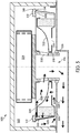
- FIG. 1 a perspective view of a rotating coalescer 100 is shown according to an example embodiment.
- FIG. 2 a cross-sectional view of the rotating coalescer 100 is shown.
- the rotating coalescer 100 includes a two-part housing having a first housing section 104 and a second housing section 102.
- the first housing section 104 and the second housing section 102 are removably secured together (e.g., via a snap-fit connection) to form the housing.
- the housing is cylindrical in shape.
- a plurality of openings 106 exist between the first housing section 104 and the second housing section 102 at a circumferential surface of the housing.
- a seal member may be placed in the openings 106 to prevent gases and oil from escaping through the openings 106.
- a wicking device e.g., a nylon rope
- the openings 106 function as oil drains.
- the housing includes a plurality of inlets 108 and an outlet 110.
- the inlets 108 receive blowby gases from a crankcase 202 of an internal combustion engine (e.g., a diesel internal combustion engine).
- the inlets 108 are formed in an axial surface of the first housing section 104.
- the blowby gases may include oils and aerosol.
- the outlet 110 routes filtered blowby gas through a hollow shaft 112.
- the hollow shaft 112 extends through the housing and defines a central axis of the rotating coalescer 100. As described in further detail below, during operation, the rotating coalescer 100 is rotated about the central axis.
- the rotating coalescer 100 includes filter media 114 positioned within the housing.
- the filter media 114 is arranged in a cylindrical shape.
- the filter media 114 may comprise a coalescing fibrous filter media.
- the filter media 114 is secured between the first housing section 104 and an endcap 116.
- the endcap 116 and the first housing section 104 include channels that receive the filter media 114.
- the filter media 114 is structured to filter blowby gases passing through the filter media 114 by coalescing and separating oils and aerosols contained in the blowby gases from the blowby gas.
- the filter media 114 is sealed with respect to the endcap 116 and with respect to the first housing section 104 such that blowby gas flowing through the inlets 108 cannot bypass the filter media 114 before exiting the housing through the outlet 110.
- the endcap 116 is spaced apart from the second housing section 102 such that a gap 118 exists between the second housing section 102 and the endcap 116. As described in further detail below, the gap 118 forms a flow channel that routes filtered blowby gases to the hollow shaft 112 and the outlet 110.
- the rotating coalescer 100 includes a drive mechanism 120.
- the drive mechanism 120 is structured to rotate the rotating coalescer 100 about the central axis.
- the drive mechanism 120 may be, for example, gear drive, an electric motor, a hydraulic drive, or the like.
- the drive mechanism 120 is operatively and rotationally coupled to the hollow shaft 112.
- the hollow shaft 112 is rotationally coupled to the housing of the rotating coalescer 100.
- the hollow shaft 112 is rotationally coupled to the second housing section 102.
- the hollow shaft 112 is rotationally coupled to the first housing section 104.
- the hollow shaft 112 is rotationally coupled to the endcap 116. In each of the arrangements, when the drive mechanism 120 rotates, the hollow shaft 112 rotates, and the hollow shaft 112 rotates the rotating coalescer 100 rotates.
- the drive mechanism 120 rotates the rotating coalescer 100.
- the flow of the blowby gases through the rotating coalescer 100 are shown by the flow arrows 120a through 120d.
- Blowby gases enter the inlets 108 from the crankcase 202 (as shown by the flow arrow 120a).
- the inlets 108 are positioned radially inside of the filter media 114 with respect to the central axis.
- the blowby gases are then passed through the filter media 114 in an inside-out manner (as shown by the flow arrow 120b).
- the filtered blowby gases are radially outside of the filter media 114 with respect to the central axis.
- the filtered blowby gases then pass through the gap 118 (as shown by the flow arrow 120c).
- the filtered blowby gases After passing through the gap 118, the filtered blowby gases return to being radially inside of the filter media 114 with respect to the central axis and then enter the hollow shaft 112 (e.g., through openings in the hollow shaft, such as perforations 122). Once inside of the hollow shaft 112, the filtered blowby gases flow through the hollow shaft 112 out of the rotating coalescer 100 via the outlet 110 (as shown by the flow arrow 120d).
- the hollow shaft 112 may route the filtered blowby gases to the ambient or into an air intake system of the internal combustion engine. As the blowby gases are filtered through the rotating coalescer 100, oil and aerosol is separated from the blowby gases.
- the openings 106 include a rope wick (e.g., a rope wick made from nylon) that prevents blowby gases from entering the rotating coalescer 100 downstream of the filter media 114 but allows for separated oil and aerosol to wick out of the housing assisted by the rotation of the rotating coalescer 100.
- a rope wick e.g., a rope wick made from nylon
- FIG. 3 a cross-sectional view of a rotating coalescer 300 is shown according to another example embodiment.
- the rotating coalescer 300 is similar to the rotating coalescer 100.
- the primary difference between the rotating coalescer 300 and the rotating coalescer 100 is the way the separated oil drains from the housing of the rotating coalescer 300.
- the rotating coalescer 300 is positioned within a crankcase 302.
- the rotating coalescer 300 includes a two-part housing having a first housing section 306 and a second housing section 304.
- the first housing section 306 and the second housing section 304 are removably secured together (e.g., via a snap-fit connection) to form the housing.
- the housing is cylindrical in shape.
- a plurality of openings 308 exist between the first housing section 306 and the second housing section 304.
- the plurality of openings 308 are formed in a circumferential surface of the housing.
- the openings 308 allow separated oil and aerosol 310 to exit the housing during operation of the rotating coalescer 300.
- the openings 308 are covered by an oil pot 312.
- the oil pot 312 is a U-shaped or C-shaped channel that collects oil and prevents blowby gases from entering the housing through the openings 308.
- the housing includes a plurality of inlets 314 and an outlet 316.
- the inlets 314 are formed in a surface of the first housing section 306.
- the inlets 314 receive blowby gases from the crankcase 302 of an internal combustion engine (e.g., a diesel internal combustion engine).
- the blowby gases may include oils and aerosol 310.
- the outlet 316 routes filtered blowby gas through a hollow shaft 318.
- the hollow shaft 318 extends through the housing and defines a central axis of the rotating coalescer 300. As described in further detail below, during operation, the rotating coalescer 300 is rotated about the central axis.
- the rotating coalescer 300 includes filter media 320 positioned within the housing.
- the filter media 320 is arranged in a cylindrical shape.
- the filter media 320 may comprise a coalescing fibrous filter media.
- the filter media 320 is structured to filter blowby gases passing through the filter media 320 by coalescing and separating oils and aerosols 310 contained in the blowby gases from the blowby bases.
- the filter media 320 is secured between the first housing section 306 and an endcap 322.
- the endcap 322 and the first housing section 306 each include channels that receive the filter media 320.
- the filter media 320 is sealed with respect to the endcap 322 and with respect to the first housing section 306 such that blowby gas flowing through the inlets 314 cannot bypass the filter media 320 before exiting the housing through the outlet 316.
- the endcap 322 is spaced apart from the second housing section 304 such that a gap exists between the second housing section 304 and the endcap 322. As described in further detail below, the gap forms a flow channel that routes filtered blowby gases to the hollow shaft 318 and the outlet 316.
- the rotating coalescer 300 includes a drive mechanism 324.
- the drive mechanism 324 is structured to rotate the rotating coalescer 300 about the central axis.
- the drive mechanism 324 may be, for example, gear drive, an electric motor, a hydraulic, or the like.
- the drive mechanism 324 is operatively and rotationally coupled to the hollow shaft 318.
- the hollow shaft 318 is rotationally coupled to the housing of the rotating coalescer 300.
- the hollow shaft 318 is rotationally coupled to at least one of the second housing section 304, the first housing section 306, the endcap 322, or a combination thereof. Accordingly, when the drive mechanism 324 rotates, the hollow shaft 318 rotates, which imparts rotation on the rotating coalescer 300.
- a lip seal 326 may be positioned between the hollow shaft 318 and the crankcase housing adjacent to the outlet 316.
- the drive mechanism 324 rotates the rotating coalescer 300.
- the flow of the blowby gases through the rotating coalescer 300 is shown by the flow arrows 328.
- Blowby gases enter the inlets 314 of the housing from the crankcase 302.
- the inlets 314 are positioned radially inside of the filter media 320 with respect to the central axis.
- the blowby gases are then passed through the filter media 320 in an inside-out manner.
- the filtered blowby gases are radially outside of the filter media 320 with respect to the central axis.
- the filtered blowby gases then pass through the gap between the endcap 322 and the second housing section 304.
- the filtered blowby gases After passing through the gap, the filtered blowby gases return to being radially inside of the filter media 320 with respect to the central axis and then enter the hollow shaft 318 (e.g., through openings 330 in the hollow shaft 318). Once inside of the hollow shaft 318, the filtered blowby gases flow through the hollow shaft 318 out of the rotating coalescer 300 via the outlet 316.
- the hollow shaft 318 may route the filtered blowby gases to the ambient or into an air intake system of the internal combustion engine.
- oil and aerosol 310 As the blowby gases are filtered through the rotating coalescer 300, oil and aerosol 310 is separated from the blowby gases.
- the separated oil and aerosol 310 is returned to the crankcase 302 via the openings 308. In some arrangements, the separated oil and aerosol 310 accumulates in an oil pot 312 after passing through the openings 308.
- FIG. 4 a cross-sectional view of a rotating coalescer 400 is shown according to still another example embodiment.
- the rotating coalescer 400 is similar to the rotating coalescer 300.
- a primary difference between the rotating coalescer 400 and the rotating coalescer 300 is the elimination of the second housing section 304 of the rotating coalescer 300. Accordingly, like numbering is used to designate like parts between the rotating coalescer 400 and the rotating coalescer 300.
- the rotating coalescer 400 is positioned within a crankcase 302.
- the rotating coalescer 400 includes a two-part housing formed by a first housing section 306 and a drive mechanism housing 404.
- the first housing section 306 and the drive mechanism housing 404 are removably secured together (e.g., via a snap-fit connection) to form the housing.
- the housing is cylindrical in shape.
- a plurality of openings 308 exist between the first housing section 306 and the drive mechanism housing 404.
- the plurality of openings 308 are formed in a circumferential surface of the housing. The openings 308 allow separated oil and aerosol 310 to exit the housing during operation of the rotating coalescer 400.
- the openings 308 are covered by an oil pot 312 (e.g., as shown in FIG. 3 ).
- the oil pot 312 is a U-shaped or C-shaped channel that collects oil and prevents blowby gases from entering the housing through the openings 308.
- the housing includes a plurality of inlets 314 and an outlet 316.
- the inlets 314 are formed in a surface of the first housing section 306.
- the inlets 314 receive blowby gases from the crankcase 302 of an internal combustion engine (e.g., a diesel internal combustion engine).
- the blowby gases may include oils and aerosol 310.
- the outlet 316 routes filtered blowby gas through a hollow shaft 318.
- the hollow shaft 318 extends through the housing and defines a central axis of the rotating coalescer 400. As described in further detail below, during operation, the rotating coalescer 400 is rotated about the central axis.
- the rotating coalescer 400 includes filter media 320 positioned within the housing.
- the filter media 320 is arranged in a cylindrical shape.
- the filter media 320 may comprise a coalescing fibrous filter media.
- the filter media 320 is structured to filter blowby gases passing through the filter media 320 by coalescing and separating oils and aerosols 310 contained in the blowby gases.
- the filter media 320 is secured between the first housing section 306 and an endcap 322.
- the endcap 322 and the first housing section 306 each include channels that receive the filter media 320.
- the filter media 320 is sealed with respect to the endcap 322 and with respect to the first housing section 306 such that blowby gas flowing through the inlets 314 cannot bypass the filter media 320 before exiting the housing through the outlet 316.
- the endcap 322 is spaced apart from the drive mechanism housing 404 such that a gap exists between the drive mechanism housing 404 and the endcap 322. As described in further detail below, the gap forms a flow channel that routes filtered blowby gases to the hollow shaft 318 and the outlet 316.
- the rotating coalescer 400 includes a drive mechanism 324.
- the drive mechanism 324 is structured to rotate the rotating coalescer 400 about the central axis.
- the drive mechanism 324 may be, for example, a gear drive, an electric motor, or the like.
- the drive mechanism 324 includes the drive mechanism housing 404.
- the drive mechanism housing 404 is rotationally operatively and coupled to drive mechanism 324 and to the hollow shaft 318.
- the hollow shaft 318 is rotationally coupled to the first housing section 306.
- the hollow shaft 318 is rotationally coupled to the endcap 322. Accordingly, when the drive mechanism 324 rotates, the drive mechanism housing 404 and the hollow shaft 318 also rotate, which thereby imparts rotation on the rotating coalescer 400.
- a lip seal 326 may be positioned between the hollow shaft 318 and the crankcase housing adjacent to the outlet 316.
- the drive mechanism 324 rotates the rotating coalescer 400.
- the flow of the blowby gases through the rotating coalescer 400 is shown by the flow arrows 328.
- Blowby gases enter the inlets 314 of the housing from the crankcase 302.
- the inlets 314 are positioned radially inside of the filter media 320 with respect to the central axis.
- the blowby gases are then passed through the filter media 320 in an inside-out manner.
- the filtered blowby gases are radially outside of the filter media 320 with respect to the central axis.
- the filtered blowby gases then pass through the gap between the endcap 322 and the drive mechanism housing 404.
- the filtered blowby gases After passing through the gap, the filtered blowby gases return to being radially inside of the filter media 320 with respect to the central axis and then enter the hollow shaft 318 (e.g., through openings 330 in the hollow shaft 318). Once inside of the hollow shaft 318, the filtered blowby gases flow through the hollow shaft 318 out of the rotating coalescer 400 via the outlet 316.
- the hollow shaft 318 may route the filtered blowby gases to the ambient or into an air intake system of the internal combustion engine.
- oil and aerosol 310 As the blowby gases are filtered through the rotating coalescer 400, oil and aerosol 310 is separated from the blowby gases.
- the separated oil and aerosol 310 is returned to the crankcase 302 via the openings 308. In some arrangements, the separated oil and aerosol 310 accumulates in an oil pot 312 after passing through the openings 308.
- FIG. 5 a cross-sectional view of a rotating coalescer 500 is shown according to still another example embodiment.
- the rotating coalescer 500 is similar to the rotating coalescer 300.
- a primary difference between the rotating coalescer 500 and the rotating coalescer 300 is the use of check valves 512 in the housing of the rotating coalescer 500. Accordingly, like numbering is used to designate like parts between the rotating coalescer 500 and the rotating coalescer 300.
- the rotating coalescer 500 is positioned within a crankcase 302.
- the rotating coalescer 500 includes a two-part housing having a first housing section 306 and a second housing section 304.
- the first housing section 306 and the second housing section 304 are removably secured together (e.g., via a snap-fit connection) to form the housing.
- the housing is cylindrical in shape.
- a plurality of openings 508 exist between the first housing section 306 and the second housing section 304.
- the plurality of openings 508 are formed in a circumferential surface of the housing.
- the openings 508 allow the separated oil and aerosol 310 to exit the housing during operation of the rotating coalescer 500.
- the openings 508 are covered with a check valve 512.
- a plurality of check valves 512 that are of the same part number, and therefore the same properties, are used to cover the plurality of openings 508.
- the check valve 512 is structured to facilitate the drainage of the separated oil and aerosol 310 from the housing if the centrifugal force of the separated oil and aerosol 310 is sufficient to overcome the back pressure of the gas outside the check valve 512. If the centrifugal force of force of the separated oil and aerosol 310 is less than the back pressure of the gas outside of the check valve 512, the separated oil and aerosol 310 will form a film 516 of the separated oil and aerosol 310 along the side wall of the first housing section 306.
- the film 516 of the separated oil and aerosol 310 will drain and the separated oil and aerosol 310 will exit the housing through the openings 508 during operation of the rotating coalescer 500.
- the back pressure of the gas outside the check valve is dependent on the check valve 512 and operating conditions outside of the housing.
- the centrifugal force is dependent on an angle 514 of the side wall of the first housing section 306 and below the check valve 512, the rotation of the coalescer 500, the radius of the coalescer 500, and the mass of the separated oil and aerosol 310.
- the housing includes a plurality of inlets 314 and an outlet 316.
- the inlets 314 are formed in a surface of the first housing section 306.
- the inlets 314 receive blowby gases from the crankcase 302 of an internal combustion engine (e.g., a diesel internal combustion engine).
- the blowby gases may include oils and aerosol 310.
- the outlet 316 routes filtered blowby gas through a hollow shaft 318.
- the hollow shaft 318 extends through the housing and defines a central axis of the rotating coalescer 500. As described in further detail below, during operation, the rotating coalescer 500 is rotated about the central axis.
- the rotating coalescer 500 includes filter media 320 positioned within the housing.
- the filter media 320 is arranged in a cylindrical shape.
- the filter media 320 may comprise a coalescing fibrous filter media.
- the filter media 320 is structured to filter blowby gases passing through the filter media 320 by coalescing and separating oils and aerosols 310 contained in the blowby gases.
- the filter media 320 is secured between the first housing section 306 and an endcap 322.
- the endcap 322 and the first housing section 306 each include channels that receive the filter media 320.
- the filter media 320 is sealed with respect to the endcap 322 and with respect to the first housing section 306 such that blowby gas flowing through the inlets 314 cannot bypass the filter media 320 before exiting the housing through the outlet 316.
- the endcap 322 is spaced apart from the second housing section 304 such that a gap exists between the second housing section 304 and the endcap 322. As described in further detail below, the gap forms a flow channel that routes filtered blowby gases to the hollow shaft 318 and the outlet 316.
- the rotating coalescer 500 includes a drive mechanism 324.
- the drive mechanism 324 is structured to rotate the rotating coalescer 500 about the central axis.
- the drive mechanism 324 may be, for example, a gear drive, an electric motor, a hydraulic, or the like.
- the drive mechanism 324 is operatively and rotationally coupled to the hollow shaft 318.
- the hollow shaft 318 is rotationally coupled to the housing of the rotating coalescer 500.
- the hollow shaft 318 is rotationally coupled to at least one of the second housing section 304, the first housing section 306, the endcap 322, or a combination thereof. Accordingly, when the drive mechanism 324 rotates, the hollow shaft 318 rotates, which imparts rotation on the rotating coalescer 500.
- a lip seal 326 may be positioned between the hollow shaft 318 and the crankcase housing adjacent to the outlet 316.
- the drive mechanism 324 rotates the rotating coalescer 500.
- the flow of the blowby gases through the rotating coalescer 500 is shown by the flow arrows 328.
- Blowby gases enter the inlets 314 of the housing from the crankcase 302.
- the inlets 314 are positioned radially inside of the filter media 320 with respect to the central axis.
- the blowby gases are then passed through the filter media 320 in an inside-out manner.
- the filtered blowby gases are radially outside of the filter media 320 with respect to the central axis.
- the filtered blowby gases then pass through the gap between the endcap 322 and the second housing section 304.
- the filtered blowby gases After passing through the gap, the filtered blowby gases return to being radially inside of the filter media 320 with respect to the central axis and then enter the hollow shaft 318 (e.g., through openings 330 in the hollow shaft 318). Once inside of the hollow shaft 318, the filtered blowby gases flow through the hollow shaft 318 out of the rotating coalescer 500 via the outlet 316.
- the hollow shaft 318 may route the filtered blowby gases to the ambient or into an air intake system of the internal combustion engine.
- oil and aerosol 310 is separated from the blowby gases. The separated oil and aerosol 310 is returned to the crankcase 302 via the openings 508 if they can overcome the back pressure of the check valve 512.
- FIG. 6 a front plan view of a rotating coalescer 600 is shown according to still another example embodiment.
- the rotating coalescer 600 is similar to the rotating coalescer 100.
- a primary difference between the rotating coalescer 600 and the rotating coalescer 100 is the use of a plurality of vanes 602 inside the housing. Accordingly, like numbering is used to designate like parts between the rotating coalescer 600 and the rotating coalescer 100.
- the plurality of vanes 602 are disposed along the inside surface of the first housing section 104.
- the plurality of vanes 602 are structured to optimize (e.g., reduce) pressure drop and laminar flow of the blowby gases that enter the inlets 108 from the crankcase 202 of an internal combustion engine.
- FIGS. 7 and 8 show graphs comparing the performance of inside-out rotating coalescers (e.g., the rotating coalescers 100, 300, 400, 500, and 600) to outside-in rotating coalescers.
- FIG. 7 shows a graph of fractional efficiency vs. aerosol size.
- FIG. 8 shows a graph of pressure drop vs. flow rate. As demonstrated in each of the graphs, the inside-out rotating coalescers are more efficient and cause a lower pressure drop than similarly configured outside-in rotating coalescers.
- Coupled and the like as used herein mean the joining of two members directly or indirectly to one another. Such joining may be stationary (e.g., permanent) or moveable (e.g., removable or releasable). Such joining may be achieved with the two members or the two members and any additional intermediate members being integrally formed as a single unitary body with one another or with the two members or the two members and any additional intermediate members being attached to one another.
Landscapes
- Chemical & Material Sciences (AREA)
- Chemical Kinetics & Catalysis (AREA)
- Engineering & Computer Science (AREA)
- Mechanical Engineering (AREA)
- General Engineering & Computer Science (AREA)
- Physics & Mathematics (AREA)
- Geometry (AREA)
- Lubrication Details And Ventilation Of Internal Combustion Engines (AREA)
Description
- The present application relates to crankcase ventilation systems.
- During operation of an internal combustion engine, a fraction of combustion gases can flow out of the combustion cylinder and into the crankcase of the engine. These gases are often called "blowby" gases. The blowby gases include a mixture of aerosols, oils, and air. If vented directly to the ambient, the blowby gases can potentially harm the environment and/or may be subject to government emissions regulations. Accordingly, the blowby gases are typically routed out of the crankcase via a crankcase ventilation system. The crankcase ventilation system may pass the blowby gases through a coalescer (i.e., a coalescing filter element) to remove a majority of the aerosols and oils contained in the blowby gases. The coalescer includes filter media. The filtered blowby gases are then either vented to the ambient (in open crankcase ventilation systems) or routed back to the air intake for the internal combustion engine for further combustion (in closed crankcase ventilation systems).
- Some crankcase ventilation systems utilize rotating coalescers that increase the filter efficiency of the coalescing filter elements by rotating the filter media during filtering. In rotating filter cartridges, the contaminants (e.g., oil droplets suspended and transported by blowby gases) are separated inside the filter media of the filter cartridge through the particle capture mechanisms of inertial impaction, interception, diffusion, and gravitational forces onto the fibers. By rotating the filter media, inertial impaction and gravitational forces are enhanced by the additional centrifugal force. Additionally, the rotation of the filter cartridge can create a pumping effect, which reduces the pressure drop through the filtration system. Rotating filter cartridges may include fibrous filters as well as centrifugal separation devices. However, many rotating coalescers are configured for outside-in flow through the filter media for ease of integration into engine compartments and crankcases. However, outside-in flow rotating coalescers suffer from high pressure drops and reduced fractional efficiency compared to inside-out flow rotating coalescers.
-
US2011180051 discloses an internal combustion engine crankcase ventilation rotating coalescer which includes an annular rotating coalescing filter element, an inlet port supplying blowby gas from the crankcase to the hollow interior of the annular rotating coalescing filter element, and an outlet port delivering cleaned separated air from the exterior of the rotating element. The direction of blowby gas is inside-out, radially outwardly from the hollow interior to the exterior. -
US5716423 discloses an inducer with a reduced number of blades, and varying density porous media disks are arranged in a deoiler mounted on a rotating shaft for total free separation of the oil from and air/oil mixture. The porous media disks are arranged with the lower density grade coming into contact with the air/oil mixture and proceeds toward the higher density grade. The arrangement of the stages of separation, the specially designed oil discharge holes and the flow geometry maximizes oil separation and removal and reduces pressure losses to control the pressure drop of the deoiler. -
FR2933626 - According to a first aspect of the invention there is provided a rotating coalescer as specified in
claim 1. - According to a second aspect of the invention, there is provided a method as specified in claim 14.
- Various examples disclosed herein relate to rotating coalescers. One such rotating coalescer includes a housing comprising a first housing section having a blowby gas inlet structured to receive crankcase blowby gases from a crankcase. The housing further comprises an oil outlet. The rotating coalescer includes an endcap and filter media. The filter media is arranged in a cylindrical shape. The filter media is coupled to and positioned between the first housing section and the endcap. The filter media is structured to filter the crankcase blowby gases passing through the filter media by coalescing and separating oils and aerosols contained in the crankcase blowby gases. The rotating coalescer includes a hollow shaft extending through the housing and positioned radially inside of the filter media. The hollow shaft forms a blowby gas outlet structured to route filtered crankcase blowby gases out of the housing. The rotating coalescer further includes a drive mechanism operatively coupled to the hollow shaft. The drive mechanism is structured to rotate the hollow shaft and the housing.
- Various other examples disclosed herein relate to a method of filtering a fluid. The method includes rotating the coalescer with a drive mechanism. The coalescer comprises a housing, an endcap, a filter media coupled to the housing and the endcap, and a hollow shaft extending through the housing and positioned radially inside of the filter media, and the drive mechanism is operatively connected to the hollow shaft. The method further includes receiving crankcase blowby gases from a crankcase through an inlet of the housing of the coalescer. The crankcase blowby gases is passed radially through the filter media in an inside-out flow. The crankcase blowby gases is filtered through the filter media. The crankcase blowby gases is passed to the hollow shaft, wherein the filtered crankcase blowby gases are radially inside of the filter media with respect to the central axis. The filtered crankcase blowby gases is routed out of the housing through a blowby gas outlet formed in the hollow shaft.
- These and other features, together with the organization and manner of operation thereof, will become apparent from the following detailed description when taken in conjunction with the accompanying drawings, wherein like elements have like numerals throughout the several drawings described below.
-
-
FIG. 1 shows a perspective view of a rotating coalescer according to an example embodiment. -
FIG. 2 shows a cross-sectional view of the rotating coalescer ofFIG. 1 . -
FIG. 3 shows a cross-sectional view of a rotating coalescer according to another example embodiment. -
FIG. 4 shows a cross-sectional view of a rotating coalescer according to a further example embodiment. -
FIG. 5 shows a cross-sectional view of a rotating coalescer according to another example embodiment. -
FIG. 6 shows a front plan view of a rotating coalescer according to a further example embodiment. -
FIG. 7 shows a graph comparing fractional efficiency of inside-out rotating coalescers and outside-in rotating coalescers. -
FIG. 8 shows a graph comparing pressure drop of inside-out rotating coalescers and outside-in rotating coalescers. - Referring to the figures generally, variations of a rotating coalescer having an inside-out flow path are described. In some arrangements, a rotating coalescer receives blowby gases to be filtered from a crankcase of an internal combustion engine. The blowby gases are routed into inlet openings in the housing of the rotating coalescer, through filter media in an inside-out manner, and out an inner outlet formed in a hollow shaft. Separated oils and aerosols may be drained from the housing through a drain or a wick (such as a nylon wick). The described inside-out rotating coalescers result in a lower restriction (e.g., pressure drop) and higher separating efficiency than outside-in rotating coalescers.
- Referring to
FIG. 1 , a perspective view of arotating coalescer 100 is shown according to an example embodiment. Referring toFIG. 2 , a cross-sectional view of therotating coalescer 100 is shown. Therotating coalescer 100 includes a two-part housing having afirst housing section 104 and asecond housing section 102. Thefirst housing section 104 and thesecond housing section 102 are removably secured together (e.g., via a snap-fit connection) to form the housing. In some arrangements, the housing is cylindrical in shape. As shown best inFIG. 2 , a plurality ofopenings 106 exist between thefirst housing section 104 and thesecond housing section 102 at a circumferential surface of the housing. In some arrangements, a seal member may be placed in theopenings 106 to prevent gases and oil from escaping through theopenings 106. In other arrangements, and as described in further detail below, a wicking device (e.g., a nylon rope) that allows separated oil to drain from the housing through theopenings 106 while preventing blowby gases from entering the housing through theopenings 106 between thefirst housing section 104 and thesecond housing section 102. In such arrangements, theopenings 106 function as oil drains. - The housing includes a plurality of
inlets 108 and anoutlet 110. Theinlets 108 receive blowby gases from acrankcase 202 of an internal combustion engine (e.g., a diesel internal combustion engine). In some arrangements, theinlets 108 are formed in an axial surface of thefirst housing section 104. The blowby gases may include oils and aerosol. As described in further detail below, theoutlet 110 routes filtered blowby gas through ahollow shaft 112. Thehollow shaft 112 extends through the housing and defines a central axis of therotating coalescer 100. As described in further detail below, during operation, therotating coalescer 100 is rotated about the central axis. - As shown best in
FIG. 2 , therotating coalescer 100 includesfilter media 114 positioned within the housing. In the arrangement shown inFIG. 2 , thefilter media 114 is arranged in a cylindrical shape. Thefilter media 114 may comprise a coalescing fibrous filter media. Thefilter media 114 is secured between thefirst housing section 104 and anendcap 116. In some arrangements, theendcap 116 and thefirst housing section 104 include channels that receive thefilter media 114. Thefilter media 114 is structured to filter blowby gases passing through thefilter media 114 by coalescing and separating oils and aerosols contained in the blowby gases from the blowby gas. Thefilter media 114 is sealed with respect to theendcap 116 and with respect to thefirst housing section 104 such that blowby gas flowing through theinlets 108 cannot bypass thefilter media 114 before exiting the housing through theoutlet 110. Theendcap 116 is spaced apart from thesecond housing section 102 such that agap 118 exists between thesecond housing section 102 and theendcap 116. As described in further detail below, thegap 118 forms a flow channel that routes filtered blowby gases to thehollow shaft 112 and theoutlet 110. - The
rotating coalescer 100 includes adrive mechanism 120. Thedrive mechanism 120 is structured to rotate therotating coalescer 100 about the central axis. Thedrive mechanism 120 may be, for example, gear drive, an electric motor, a hydraulic drive, or the like. Thedrive mechanism 120 is operatively and rotationally coupled to thehollow shaft 112. Thehollow shaft 112 is rotationally coupled to the housing of therotating coalescer 100. In some arrangements, thehollow shaft 112 is rotationally coupled to thesecond housing section 102. In other arrangements, thehollow shaft 112 is rotationally coupled to thefirst housing section 104. In further arrangements, thehollow shaft 112 is rotationally coupled to theendcap 116. In each of the arrangements, when thedrive mechanism 120 rotates, thehollow shaft 112 rotates, and thehollow shaft 112 rotates therotating coalescer 100 rotates. - During operation, the
drive mechanism 120 rotates therotating coalescer 100. The flow of the blowby gases through therotating coalescer 100 are shown by theflow arrows 120a through 120d. Blowby gases enter theinlets 108 from the crankcase 202 (as shown by theflow arrow 120a). Theinlets 108 are positioned radially inside of thefilter media 114 with respect to the central axis. The blowby gases are then passed through thefilter media 114 in an inside-out manner (as shown by theflow arrow 120b). At this point, the filtered blowby gases are radially outside of thefilter media 114 with respect to the central axis. The filtered blowby gases then pass through the gap 118 (as shown by theflow arrow 120c). After passing through thegap 118, the filtered blowby gases return to being radially inside of thefilter media 114 with respect to the central axis and then enter the hollow shaft 112 (e.g., through openings in the hollow shaft, such as perforations 122). Once inside of thehollow shaft 112, the filtered blowby gases flow through thehollow shaft 112 out of therotating coalescer 100 via the outlet 110 (as shown by theflow arrow 120d). Thehollow shaft 112 may route the filtered blowby gases to the ambient or into an air intake system of the internal combustion engine. As the blowby gases are filtered through therotating coalescer 100, oil and aerosol is separated from the blowby gases. In some arrangements, theopenings 106 include a rope wick (e.g., a rope wick made from nylon) that prevents blowby gases from entering therotating coalescer 100 downstream of thefilter media 114 but allows for separated oil and aerosol to wick out of the housing assisted by the rotation of therotating coalescer 100. - Referring to
FIG. 3 , a cross-sectional view of arotating coalescer 300 is shown according to another example embodiment. Therotating coalescer 300 is similar to therotating coalescer 100. The primary difference between therotating coalescer 300 and therotating coalescer 100 is the way the separated oil drains from the housing of therotating coalescer 300. Therotating coalescer 300 is positioned within acrankcase 302. Therotating coalescer 300 includes a two-part housing having afirst housing section 306 and asecond housing section 304. Thefirst housing section 306 and thesecond housing section 304 are removably secured together (e.g., via a snap-fit connection) to form the housing. In some arrangements, the housing is cylindrical in shape. A plurality ofopenings 308 exist between thefirst housing section 306 and thesecond housing section 304. The plurality ofopenings 308 are formed in a circumferential surface of the housing. Theopenings 308 allow separated oil andaerosol 310 to exit the housing during operation of therotating coalescer 300. In some arrangements, theopenings 308 are covered by anoil pot 312. Theoil pot 312 is a U-shaped or C-shaped channel that collects oil and prevents blowby gases from entering the housing through theopenings 308. - The housing includes a plurality of
inlets 314 and anoutlet 316. In some arrangements, theinlets 314 are formed in a surface of thefirst housing section 306. Theinlets 314 receive blowby gases from thecrankcase 302 of an internal combustion engine (e.g., a diesel internal combustion engine). The blowby gases may include oils andaerosol 310. As described in further detail below, theoutlet 316 routes filtered blowby gas through ahollow shaft 318. Thehollow shaft 318 extends through the housing and defines a central axis of therotating coalescer 300. As described in further detail below, during operation, therotating coalescer 300 is rotated about the central axis. - The
rotating coalescer 300 includesfilter media 320 positioned within the housing. In the embodiment depicted inFIG. 3 , thefilter media 320 is arranged in a cylindrical shape. Thefilter media 320 may comprise a coalescing fibrous filter media. Thefilter media 320 is structured to filter blowby gases passing through thefilter media 320 by coalescing and separating oils andaerosols 310 contained in the blowby gases from the blowby bases. Thefilter media 320 is secured between thefirst housing section 306 and anendcap 322. In some arrangements, theendcap 322 and thefirst housing section 306 each include channels that receive thefilter media 320. Thefilter media 320 is sealed with respect to theendcap 322 and with respect to thefirst housing section 306 such that blowby gas flowing through theinlets 314 cannot bypass thefilter media 320 before exiting the housing through theoutlet 316. Theendcap 322 is spaced apart from thesecond housing section 304 such that a gap exists between thesecond housing section 304 and theendcap 322. As described in further detail below, the gap forms a flow channel that routes filtered blowby gases to thehollow shaft 318 and theoutlet 316. - The
rotating coalescer 300 includes adrive mechanism 324. Thedrive mechanism 324 is structured to rotate therotating coalescer 300 about the central axis. Thedrive mechanism 324 may be, for example, gear drive, an electric motor, a hydraulic, or the like. Thedrive mechanism 324 is operatively and rotationally coupled to thehollow shaft 318. Thehollow shaft 318 is rotationally coupled to the housing of therotating coalescer 300. In some arrangements, thehollow shaft 318 is rotationally coupled to at least one of thesecond housing section 304, thefirst housing section 306, theendcap 322, or a combination thereof. Accordingly, when thedrive mechanism 324 rotates, thehollow shaft 318 rotates, which imparts rotation on therotating coalescer 300. Alip seal 326 may be positioned between thehollow shaft 318 and the crankcase housing adjacent to theoutlet 316. - During operation, the
drive mechanism 324 rotates therotating coalescer 300. The flow of the blowby gases through therotating coalescer 300 is shown by theflow arrows 328. Blowby gases enter theinlets 314 of the housing from thecrankcase 302. Theinlets 314 are positioned radially inside of thefilter media 320 with respect to the central axis. The blowby gases are then passed through thefilter media 320 in an inside-out manner. At this point, the filtered blowby gases are radially outside of thefilter media 320 with respect to the central axis. The filtered blowby gases then pass through the gap between theendcap 322 and thesecond housing section 304. After passing through the gap, the filtered blowby gases return to being radially inside of thefilter media 320 with respect to the central axis and then enter the hollow shaft 318 (e.g., throughopenings 330 in the hollow shaft 318). Once inside of thehollow shaft 318, the filtered blowby gases flow through thehollow shaft 318 out of therotating coalescer 300 via theoutlet 316. Thehollow shaft 318 may route the filtered blowby gases to the ambient or into an air intake system of the internal combustion engine. As the blowby gases are filtered through therotating coalescer 300, oil andaerosol 310 is separated from the blowby gases. The separated oil andaerosol 310 is returned to thecrankcase 302 via theopenings 308. In some arrangements, the separated oil andaerosol 310 accumulates in anoil pot 312 after passing through theopenings 308. - Referring to
FIG. 4 , a cross-sectional view of arotating coalescer 400 is shown according to still another example embodiment. Therotating coalescer 400 is similar to therotating coalescer 300. A primary difference between therotating coalescer 400 and therotating coalescer 300 is the elimination of thesecond housing section 304 of therotating coalescer 300. Accordingly, like numbering is used to designate like parts between therotating coalescer 400 and therotating coalescer 300. - The
rotating coalescer 400 is positioned within acrankcase 302. Therotating coalescer 400 includes a two-part housing formed by afirst housing section 306 and adrive mechanism housing 404. In some arrangements, thefirst housing section 306 and thedrive mechanism housing 404 are removably secured together (e.g., via a snap-fit connection) to form the housing. In some arrangements, the housing is cylindrical in shape. A plurality ofopenings 308 exist between thefirst housing section 306 and thedrive mechanism housing 404. The plurality ofopenings 308 are formed in a circumferential surface of the housing. Theopenings 308 allow separated oil andaerosol 310 to exit the housing during operation of therotating coalescer 400. In some arrangements, theopenings 308 are covered by an oil pot 312 (e.g., as shown inFIG. 3 ). In such arrangements, theoil pot 312 is a U-shaped or C-shaped channel that collects oil and prevents blowby gases from entering the housing through theopenings 308. - The housing includes a plurality of
inlets 314 and anoutlet 316. In some arrangements, theinlets 314 are formed in a surface of thefirst housing section 306. Theinlets 314 receive blowby gases from thecrankcase 302 of an internal combustion engine (e.g., a diesel internal combustion engine). The blowby gases may include oils andaerosol 310. As described in further detail below, theoutlet 316 routes filtered blowby gas through ahollow shaft 318. Thehollow shaft 318 extends through the housing and defines a central axis of therotating coalescer 400. As described in further detail below, during operation, therotating coalescer 400 is rotated about the central axis. - The
rotating coalescer 400 includesfilter media 320 positioned within the housing. In the embodiment depicted inFIG. 4 , thefilter media 320 is arranged in a cylindrical shape. Thefilter media 320 may comprise a coalescing fibrous filter media. Thefilter media 320 is structured to filter blowby gases passing through thefilter media 320 by coalescing and separating oils andaerosols 310 contained in the blowby gases. Thefilter media 320 is secured between thefirst housing section 306 and anendcap 322. In some arrangements, theendcap 322 and thefirst housing section 306 each include channels that receive thefilter media 320. Thefilter media 320 is sealed with respect to theendcap 322 and with respect to thefirst housing section 306 such that blowby gas flowing through theinlets 314 cannot bypass thefilter media 320 before exiting the housing through theoutlet 316. Theendcap 322 is spaced apart from thedrive mechanism housing 404 such that a gap exists between thedrive mechanism housing 404 and theendcap 322. As described in further detail below, the gap forms a flow channel that routes filtered blowby gases to thehollow shaft 318 and theoutlet 316. - The
rotating coalescer 400 includes adrive mechanism 324. Thedrive mechanism 324 is structured to rotate therotating coalescer 400 about the central axis. Thedrive mechanism 324 may be, for example, a gear drive, an electric motor, or the like. Thedrive mechanism 324 includes thedrive mechanism housing 404. Thedrive mechanism housing 404 is rotationally operatively and coupled to drivemechanism 324 and to thehollow shaft 318. In some arrangements, thehollow shaft 318 is rotationally coupled to thefirst housing section 306. In further arrangements, thehollow shaft 318 is rotationally coupled to theendcap 322. Accordingly, when thedrive mechanism 324 rotates, thedrive mechanism housing 404 and thehollow shaft 318 also rotate, which thereby imparts rotation on therotating coalescer 400. Alip seal 326 may be positioned between thehollow shaft 318 and the crankcase housing adjacent to theoutlet 316. - During operation, the
drive mechanism 324 rotates therotating coalescer 400. The flow of the blowby gases through therotating coalescer 400 is shown by theflow arrows 328. Blowby gases enter theinlets 314 of the housing from thecrankcase 302. Theinlets 314 are positioned radially inside of thefilter media 320 with respect to the central axis. The blowby gases are then passed through thefilter media 320 in an inside-out manner. At this point, the filtered blowby gases are radially outside of thefilter media 320 with respect to the central axis. The filtered blowby gases then pass through the gap between theendcap 322 and thedrive mechanism housing 404. After passing through the gap, the filtered blowby gases return to being radially inside of thefilter media 320 with respect to the central axis and then enter the hollow shaft 318 (e.g., throughopenings 330 in the hollow shaft 318). Once inside of thehollow shaft 318, the filtered blowby gases flow through thehollow shaft 318 out of therotating coalescer 400 via theoutlet 316. Thehollow shaft 318 may route the filtered blowby gases to the ambient or into an air intake system of the internal combustion engine. As the blowby gases are filtered through therotating coalescer 400, oil andaerosol 310 is separated from the blowby gases. The separated oil andaerosol 310 is returned to thecrankcase 302 via theopenings 308. In some arrangements, the separated oil andaerosol 310 accumulates in anoil pot 312 after passing through theopenings 308. - Referring to
FIG. 5 , a cross-sectional view of arotating coalescer 500 is shown according to still another example embodiment. Therotating coalescer 500 is similar to therotating coalescer 300. A primary difference between therotating coalescer 500 and therotating coalescer 300 is the use ofcheck valves 512 in the housing of therotating coalescer 500. Accordingly, like numbering is used to designate like parts between therotating coalescer 500 and therotating coalescer 300. - The
rotating coalescer 500 is positioned within acrankcase 302. Therotating coalescer 500 includes a two-part housing having afirst housing section 306 and asecond housing section 304. Thefirst housing section 306 and thesecond housing section 304 are removably secured together (e.g., via a snap-fit connection) to form the housing. In some arrangements, the housing is cylindrical in shape. A plurality ofopenings 508 exist between thefirst housing section 306 and thesecond housing section 304. The plurality ofopenings 508 are formed in a circumferential surface of the housing. Theopenings 508 allow the separated oil andaerosol 310 to exit the housing during operation of therotating coalescer 500. In some arrangements, theopenings 508 are covered with acheck valve 512. In some arrangements, a plurality ofcheck valves 512 that are of the same part number, and therefore the same properties, are used to cover the plurality ofopenings 508. - The
check valve 512 is structured to facilitate the drainage of the separated oil andaerosol 310 from the housing if the centrifugal force of the separated oil andaerosol 310 is sufficient to overcome the back pressure of the gas outside thecheck valve 512. If the centrifugal force of force of the separated oil andaerosol 310 is less than the back pressure of the gas outside of thecheck valve 512, the separated oil andaerosol 310 will form afilm 516 of the separated oil andaerosol 310 along the side wall of thefirst housing section 306. When the pressure of the centrifugal force of the separated oil andaerosol 310 is greater than the back pressure of the gas outside of thecheck valve 512, thefilm 516 of the separated oil andaerosol 310 will drain and the separated oil andaerosol 310 will exit the housing through theopenings 508 during operation of therotating coalescer 500. As will be appreciated, the back pressure of the gas outside the check valve is dependent on thecheck valve 512 and operating conditions outside of the housing. The centrifugal force is dependent on anangle 514 of the side wall of thefirst housing section 306 and below thecheck valve 512, the rotation of thecoalescer 500, the radius of thecoalescer 500, and the mass of the separated oil andaerosol 310. For example, when theangle 514 of the side wall of thefirst housing section 306 is five degrees, the rotation of thecoalescer 500 is 3000 rpm, the radius is 0.1 m, and the gas pressure (Fp ) is 20 mbar (e.g. 200 kg/m2), the centrifugal force (Fc ) will overcome the gas pressure when thefilm 516 reaches a thickness (t) of 0.27 mm.


- The housing includes a plurality of
inlets 314 and anoutlet 316. In some arrangements, theinlets 314 are formed in a surface of thefirst housing section 306. Theinlets 314 receive blowby gases from thecrankcase 302 of an internal combustion engine (e.g., a diesel internal combustion engine). The blowby gases may include oils andaerosol 310. As described in further detail below, theoutlet 316 routes filtered blowby gas through ahollow shaft 318. Thehollow shaft 318 extends through the housing and defines a central axis of therotating coalescer 500. As described in further detail below, during operation, therotating coalescer 500 is rotated about the central axis. - The
rotating coalescer 500 includesfilter media 320 positioned within the housing. In the embodiment depicted inFIG. 5 , thefilter media 320 is arranged in a cylindrical shape. Thefilter media 320 may comprise a coalescing fibrous filter media. Thefilter media 320 is structured to filter blowby gases passing through thefilter media 320 by coalescing and separating oils andaerosols 310 contained in the blowby gases. Thefilter media 320 is secured between thefirst housing section 306 and anendcap 322. In some arrangements, theendcap 322 and thefirst housing section 306 each include channels that receive thefilter media 320. Thefilter media 320 is sealed with respect to theendcap 322 and with respect to thefirst housing section 306 such that blowby gas flowing through theinlets 314 cannot bypass thefilter media 320 before exiting the housing through theoutlet 316. Theendcap 322 is spaced apart from thesecond housing section 304 such that a gap exists between thesecond housing section 304 and theendcap 322. As described in further detail below, the gap forms a flow channel that routes filtered blowby gases to thehollow shaft 318 and theoutlet 316. - The
rotating coalescer 500 includes adrive mechanism 324. Thedrive mechanism 324 is structured to rotate therotating coalescer 500 about the central axis. Thedrive mechanism 324 may be, for example, a gear drive, an electric motor, a hydraulic, or the like. Thedrive mechanism 324 is operatively and rotationally coupled to thehollow shaft 318. Thehollow shaft 318 is rotationally coupled to the housing of therotating coalescer 500. In some arrangements, thehollow shaft 318 is rotationally coupled to at least one of thesecond housing section 304, thefirst housing section 306, theendcap 322, or a combination thereof. Accordingly, when thedrive mechanism 324 rotates, thehollow shaft 318 rotates, which imparts rotation on therotating coalescer 500. Alip seal 326 may be positioned between thehollow shaft 318 and the crankcase housing adjacent to theoutlet 316. - During operation, the
drive mechanism 324 rotates therotating coalescer 500. The flow of the blowby gases through therotating coalescer 500 is shown by theflow arrows 328. Blowby gases enter theinlets 314 of the housing from thecrankcase 302. Theinlets 314 are positioned radially inside of thefilter media 320 with respect to the central axis. The blowby gases are then passed through thefilter media 320 in an inside-out manner. At this point, the filtered blowby gases are radially outside of thefilter media 320 with respect to the central axis. The filtered blowby gases then pass through the gap between theendcap 322 and thesecond housing section 304. After passing through the gap, the filtered blowby gases return to being radially inside of thefilter media 320 with respect to the central axis and then enter the hollow shaft 318 (e.g., throughopenings 330 in the hollow shaft 318). Once inside of thehollow shaft 318, the filtered blowby gases flow through thehollow shaft 318 out of therotating coalescer 500 via theoutlet 316. Thehollow shaft 318 may route the filtered blowby gases to the ambient or into an air intake system of the internal combustion engine. As the blowby gases are filtered through therotating coalescer 500, oil andaerosol 310 is separated from the blowby gases. The separated oil andaerosol 310 is returned to thecrankcase 302 via theopenings 508 if they can overcome the back pressure of thecheck valve 512. - Referring to
FIG. 6 , a front plan view of arotating coalescer 600 is shown according to still another example embodiment. Therotating coalescer 600 is similar to therotating coalescer 100. A primary difference between therotating coalescer 600 and therotating coalescer 100 is the use of a plurality ofvanes 602 inside the housing. Accordingly, like numbering is used to designate like parts between therotating coalescer 600 and therotating coalescer 100. In some embodiments, the plurality ofvanes 602 are disposed along the inside surface of thefirst housing section 104. The plurality ofvanes 602 are structured to optimize (e.g., reduce) pressure drop and laminar flow of the blowby gases that enter theinlets 108 from thecrankcase 202 of an internal combustion engine. -
FIGS. 7 and8 show graphs comparing the performance of inside-out rotating coalescers (e.g., therotating coalescers FIG. 7 shows a graph of fractional efficiency vs. aerosol size.FIG. 8 shows a graph of pressure drop vs. flow rate. As demonstrated in each of the graphs, the inside-out rotating coalescers are more efficient and cause a lower pressure drop than similarly configured outside-in rotating coalescers. - It should be noted that any use of the term "example" herein to describe various embodiments is intended to indicate that such embodiments are possible examples, representations, and/or illustrations of possible embodiments (and such term is not intended to connote that such embodiments are necessarily extraordinary or superlative examples).
- The terms "coupled" and the like as used herein mean the joining of two members directly or indirectly to one another. Such joining may be stationary (e.g., permanent) or moveable (e.g., removable or releasable). Such joining may be achieved with the two members or the two members and any additional intermediate members being integrally formed as a single unitary body with one another or with the two members or the two members and any additional intermediate members being attached to one another.
- It is important to note that the construction and arrangement of the various example embodiments are illustrative only. Although only a few embodiments have been described in detail in this disclosure, those skilled in the art who review this disclosure will readily appreciate that many modifications are possible (e.g., variations in sizes, dimensions, structures, shapes and proportions of the various elements, values of parameters, mounting arrangements, use of materials, colors, orientations, etc.) without materially departing from the novel teachings and advantages of the subject matter described herein. For example, elements shown as integrally formed may be constructed of multiple parts or elements, the position of elements may be reversed or otherwise varied, and the nature or number of discrete elements or positions may be altered or varied. The order or sequence of any process or method steps may be varied or re-sequenced according to alternative embodiments. Additionally, features from particular embodiments may be combined with features from other embodiments as would be understood by one of ordinary skill in the art. Other substitutions, modifications, changes and omissions may also be made in the design, operating conditions and arrangement of the various example embodiments without departing from the scope of the present invention as defined by the claims.
Claims (15)
- A rotating coalescer (100, 300, 400, 500, 600) comprising:a housing comprising:a first housing section (104, 306) having blowby gas inlets (108, 314) structured to receive crankcase blowby gases from a crankcase (202, 302); andan oil outlet;an endcap (116, 322);filter media (114, 320) arranged in a cylindrical shape, wherein the blowby gas inlets are positioned radially inside of the filter media with respect to the central axis;the filter media coupled to and positioned between the first housing section and the endcap, the filter media structured to receive unfiltered crankcase blowby gases from the blowby gas inlets and filter the crankcase blowby gases passing radially through the filter media by coalescing and separating oils and aerosols contained in the crankcase blowby gases such that the blowby gases pass through the filter media in an inside-out flow;a hollow shaft (112, 318) extending through the housing and positioned radially inside of the filter media, the hollow shaft forming a blowby gas outlet structured to route filtered crankcase blowby gases out of the housing; anda drive mechanism (120, 324) operatively coupled to the hollow shaft, the drive mechanism structured to rotate the hollow shaft and the housing.
- The rotating coalescer (100, 300, 400, 500, 600) of claim 1, further comprising a second housing section (102, 304) removably coupled to the first housing section (104, 306).
- The rotating coalescer (100, 300, 400, 500, 600) of claim 2, wherein the oil outlet is defined by a gap between the first housing section (104, 306) and the second housing section (102, 304).
- The rotating coalescer (100) of claim 3, wherein the gap includes a nylon rope.
- The rotating coalescer (100, 300, 400, 500, 600) of claim 1, wherein the rotating coalescer is positioned within the crankcase (202, 302).
- The rotating coalescer (100, 300, 400, 500, 600) of claim 1, wherein the hollow shaft (112, 318) is rotationally coupled to the first housing section (104, 306).
- The rotating coalescer (100, 300, 400, 500, 600) of claim 2, wherein the hollow shaft (112, 318) is rotationally coupled to the second housing section (102, 304); or wherein,
the hollow shaft is rotationally coupled to the endcap (116, 322). - The rotating coalescer (100, 300, 400, 500, 600) of claim 1, wherein the drive mechanism (120, 324) comprises at least one of a gear drive, an electric motor, and a hydraulic.
- The rotating coalescer (300, 400, 500) of claim 1, further comprising a lip seal (326) disposed between the hollow shaft (318) and the housing adjacent to the blowby gas outlet (316).
- The rotating coalescer (100, 300, 400, 500, 600) of claim 1, further comprising a flow channel defined by a gap (118) between the second housing section (102, 304) and the endcap (116, 322), the flow channel structured to route filtered crankcase blowby gas to the hollow shaft (112, 318).
- The rotating coalescer (300, 400, 500) of claim 1, wherein the endcap (322) further comprises a first channel and the first housing section (306) comprises a second channel, wherein the first channel and the second channel are structured to receive the filter media (320); wherein optionally,
the first channel and the second channel are structured to route crankcase blowby gas through the filter media. - The rotating coalescer (100, 300, 400, 500, 600) of claim 1, wherein the first housing section (104, 306) and the second housing section (102, 304) are removably coupled through a snap fit connection; or wherein,
the rotating coalescer further comprises an oil pot (312) covering the oil outlet. - The rotating coalescer (400) of claim 1, wherein the first housing section (306) is coupled to a drive mechanism housing (404); or wherein,
the rotating coalescer (500) further comprises a check valve (512) covering the oil outlet, the check valve facilitating drainage of separated oils and aerosols from the housing when a back pressure of gas outside of the check valve is overcome; or wherein,
the housing further comprises a plurality of vanes (602) along an inside surface of the housing. - A method of filtering a fluid, the method comprising:rotating a coalescer (100, 300, 400, 500, 600) with a drive mechanism (120, 324), the coalescer comprising a housing, an endcap (116, 322), a filter media (114, 320) coupled to the housing and the endcap, and a hollow shaft (112, 318) extending through the housing and positioned radially inside of the filter media, wherein the drive mechanism is operatively connected to the hollow shaft;receiving crankcase blowby gases from a crankcase (202, 302) through inlets (108, 314) of the housing of the coalescer;passing the crankcase blowby gases radially through the filter media in an inside-out flow;filtering the crankcase blowby gases through the filter media;passing the filtered crankcase blowby gases to the hollow shaft, wherein the filtered crankcase blowby gases are radially inside of the filter media with respect to a central axis when received by the hollow shaft; androuting the filtered crankcase blowby gases out of the housing through a blowby gas outlet formed in the hollow shaft.
- The method of claim 14, wherein filtering the crankcase blowby gases through the filter media (114, 320) further includes separating oils and aerosols from the crankcase blowby gases, and further comprising:
draining the separated oils and aerosols through an oil outlet in the housing; wherein optionally,
the separated oils and aerosols are drained through a check valve (512) disposed in the oil outlet in response to a back pressure of gas outside of the check valve being overcome.
Applications Claiming Priority (2)
| Application Number | Priority Date | Filing Date | Title |
|---|---|---|---|
| US201662328880P | 2016-04-28 | 2016-04-28 | |
| PCT/US2017/029315 WO2017189516A1 (en) | 2016-04-28 | 2017-04-25 | Inside-out rotating coalescer with gas exit through hollow shaft |
Publications (3)
| Publication Number | Publication Date |
|---|---|
| EP3449106A1 EP3449106A1 (en) | 2019-03-06 |
| EP3449106A4 EP3449106A4 (en) | 2019-11-27 |
| EP3449106B1 true EP3449106B1 (en) | 2021-04-07 |
Family
ID=60160093
Family Applications (1)
| Application Number | Title | Priority Date | Filing Date |
|---|---|---|---|
| EP17790235.0A Active EP3449106B1 (en) | 2016-04-28 | 2017-04-25 | Inside-out rotating coalescer with gas exit through hollow shaft |
Country Status (4)
| Country | Link |
|---|---|
| US (4) | US10711669B2 (en) |
| EP (1) | EP3449106B1 (en) |
| CN (2) | CN112901310B (en) |
| WO (1) | WO2017189516A1 (en) |
Families Citing this family (20)
| Publication number | Priority date | Publication date | Assignee | Title |
|---|---|---|---|---|
| US10543442B2 (en) | 2015-03-30 | 2020-01-28 | Cummins Filtration Ip, Inc. | Multiple stage rotating coalescer devices |
| WO2016200928A1 (en) | 2015-06-09 | 2016-12-15 | Cummins Filtration Ip, Inc. | Systems and methods for rotating coalescers maintaining positive recirculation through a dynamic seal |
| CN107614841B (en) | 2015-06-09 | 2020-02-21 | 康明斯过滤Ip公司 | System and method for contact sealing using a low friction rotary coalescer |
| CN107847839B (en) | 2015-08-21 | 2020-05-29 | 康明斯过滤Ip公司 | High speed rotating crankcase ventilation filter media and media pack |
| CN111001225B (en) | 2015-08-28 | 2021-11-19 | 康明斯过滤Ip公司 | Rotating coalescer element with directional liquid drain and gas outlet |
| EP3449106B1 (en) | 2016-04-28 | 2021-04-07 | Cummins Filtration IP, Inc. | Inside-out rotating coalescer with gas exit through hollow shaft |
| WO2019112755A1 (en) | 2017-12-06 | 2019-06-13 | Cummins Filtration Ip, Inc. | Crankcase ventilation systems having a swirl breaker to reduce pressure drop in tangentially exiting fluids |
| IT201800020413A1 (en) * | 2018-12-20 | 2020-06-20 | Ufi Filters Spa | BLOW-BY GAS FILTRATION ASSEMBLY |
| KR20220101564A (en) * | 2019-05-29 | 2022-07-19 | 유에프아이 필터즈 소시에떼 퍼 아찌오니 | Blow-by gas filtration assembly with support and control shafts |
| IT201900014283A1 (en) * | 2019-08-07 | 2021-02-07 | Ufi Filters Spa | BLOW-BY GAS FILTRATION ASSEMBLY WITH SHAFT WITH OUTLET PORTION |
| CN112824656B (en) * | 2019-11-21 | 2024-12-17 | 上海欧菲滤清器有限公司 | Blowby gas filter assembly |
| CN112824655A (en) * | 2019-11-21 | 2021-05-21 | 上海欧菲滤清器有限公司 | Blow-by gas filter assembly with support and control shaft |
| CN111140313B (en) * | 2019-12-20 | 2021-04-16 | 潍柴动力股份有限公司 | Multi-mode driving oil-gas separator control system and control method |
| CN113123846B (en) * | 2019-12-30 | 2024-10-15 | 上海欧菲滤清器有限公司 | Blow-by filter assembly having a shaft with a locking insert |
| EP4097339B1 (en) * | 2020-01-28 | 2025-01-29 | Cummins Filtration Inc. | Electric motor integrated rotating crankcase ventilation filter assemblies |
| CN112065533B (en) * | 2020-08-04 | 2021-11-19 | 潍柴动力股份有限公司 | Oil-gas pre-separation device and engine |
| CN113982939B (en) * | 2021-09-06 | 2022-07-29 | 鑫磊压缩机股份有限公司 | Horizontal oil-gas separation's air compressor machine structure |
| CN114412643B (en) * | 2022-01-25 | 2024-08-06 | 中国航发贵阳发动机设计研究所 | Multi-stage oil return device integrating oil-gas separation function |
| WO2025245008A1 (en) * | 2024-05-24 | 2025-11-27 | Cummins Filtration Inc. | Rotating crankcase ventilation system |
| WO2026159602A1 (en) | 2025-01-22 | 2026-07-30 | S.T.C. S.R.L. | Improved rotating separator |
Family Cites Families (92)
| Publication number | Priority date | Publication date | Assignee | Title |
|---|---|---|---|---|
| US2788125A (en) | 1953-07-31 | 1957-04-09 | Edmond F Webb | Fuel filter |
| US2937755A (en) | 1954-09-13 | 1960-05-24 | Acf Ind Inc | Filter for electric fuel pump |
| US2905327A (en) | 1958-04-03 | 1959-09-22 | Tillotson Mfg Co | Fuel filter |
| NL285656A (en) | 1961-11-22 | |||
| US3362155A (en) | 1965-03-29 | 1968-01-09 | Gen Electric | Axial flow separator |
| DE1941194U (en) | 1966-03-23 | 1966-06-23 | Draftex G M B H | SEALING OR DECORATIVE STRIP SLIDED ON A FLANGE. |
| US3451551A (en) | 1967-09-15 | 1969-06-24 | Aero Flow Dynamics Inc | Free-flow filter bypass valve |
| JPS5392973A (en) | 1977-01-26 | 1978-08-15 | Sanetsu Kk | Oil mist remover |
| JPS5933890Y2 (en) | 1978-03-07 | 1984-09-20 | 株式会社デンソー | Air cleaner element for internal combustion engine |
| US4502956A (en) | 1982-02-24 | 1985-03-05 | Racor Industries, Inc. | Filter assembly |
| US4482365A (en) | 1982-03-01 | 1984-11-13 | Pall Corporation | Vortex air cleaner and self-cleaning barrier filter assembly for supercharged engines |
| US4487618A (en) * | 1982-08-19 | 1984-12-11 | La-Man Corporation | Airline vapor trap |
| US4516994A (en) | 1984-04-11 | 1985-05-14 | Vilter Manufacturing Corporation | Apparatus for separating liquid droplets from gas |
| US4514193A (en) | 1984-07-26 | 1985-04-30 | Donaldson Company, Inc. | Self-cleaning air cleaner assembly with rotating filter element and inertial pre-cleaner |
| DE3737221C1 (en) | 1987-11-03 | 1989-04-27 | Mtu Muenchen Gmbh | OEl air separator |
| US5056935A (en) | 1990-11-05 | 1991-10-15 | General Electric Company | Oil film damper seal ring |
| US5387342A (en) | 1992-06-10 | 1995-02-07 | Charles W. Taggart | Centrifugal separator and method |
| US5401706A (en) | 1993-01-06 | 1995-03-28 | Semco Incorporated | Desiccant-coated substrate and method of manufacture |
| GB9320231D0 (en) | 1993-10-01 | 1993-11-17 | Boc Group Plc | Gas-liquid separation methods and apparatus |
| US5462658A (en) | 1994-01-14 | 1995-10-31 | Thermo King Corporation | Fuel filter system |
| US5716423A (en) * | 1995-12-21 | 1998-02-10 | United Technologies Corporation | Multi-stage deoiler with porous media |
| US6033450A (en) | 1995-12-21 | 2000-03-07 | United Technologies Corporation | Deoiler shaft vortex separator |
| US6123061A (en) | 1997-02-25 | 2000-09-26 | Cummins Engine Company, Inc. | Crankcase ventilation system |
| JPH11141325A (en) | 1997-11-11 | 1999-05-25 | Toyota Autom Loom Works Ltd | Blow-by gas oil recirculation device |
| US6183407B1 (en) | 1998-04-02 | 2001-02-06 | Alfa Laval Ab | Centrifugal separator having axially-extending, angled separation discs |
| US6139595A (en) | 1998-09-18 | 2000-10-31 | Fleetguard, Inc. | Air/oil coalescer with centrifugally assisted drainage |
| US6876760B1 (en) | 2000-12-04 | 2005-04-05 | Cytokinetics, Inc. | Classifying cells based on information contained in cell images |
| SE516944C2 (en) * | 1999-06-30 | 2002-03-26 | Volvo Lastvagnar Ab | Oil separator for small particles |
| US6652439B2 (en) | 2000-04-04 | 2003-11-25 | Fleetguard, Inc. | Disposable rotor shell with integral molded spiral vanes |
| DE10044615A1 (en) | 2000-09-09 | 2002-04-04 | Mahle Filtersysteme Gmbh | Ventilation device for a crankcase |
| US6499285B1 (en) | 2001-08-01 | 2002-12-31 | Rolls-Royce Corporation | Particle separator for a gas turbine engine |
| US6640792B2 (en) | 2001-08-16 | 2003-11-04 | Commins Engine Company, Inc. | Air/oil coalescer with an improved centrifugally assisted drainage |
| US20040071328A1 (en) | 2001-09-07 | 2004-04-15 | Vaisberg Eugeni A. | Classifying cells based on information contained in cell images |
| US6517612B1 (en) | 2001-10-29 | 2003-02-11 | Gore Enterprise Holdings, Inc. | Centrifugal filtration device |
| SE0201982D0 (en) | 2002-06-24 | 2002-06-24 | Alfa Laval Corp Ab | Ways to clean crankcase gas and a gas purifier separator |
| US6827764B2 (en) | 2002-07-25 | 2004-12-07 | 3M Innovative Properties Company | Molded filter element that contains thermally bonded staple fibers and electrically-charged microfibers |
| US7306715B2 (en) | 2002-08-05 | 2007-12-11 | Denso Corporation | Pump module |
| DE20302824U1 (en) | 2003-02-21 | 2004-07-08 | Hengst Gmbh & Co.Kg | Oil separator for cleaning crankcase ventilation gas of an internal combustion engine containing oil mist |
| US7235177B2 (en) * | 2003-04-23 | 2007-06-26 | Fleetguard, Inc. | Integral air/oil coalescer for a centrifuge |
| GB0417458D0 (en) | 2004-08-05 | 2004-09-08 | Domnick Hunter Ltd | Filter assembly |
| US7614390B2 (en) * | 2007-08-23 | 2009-11-10 | Cummins Filtration Ip Inc. | Two stage drainage gas-liquid separator |
| EP1645320A1 (en) | 2004-10-08 | 2006-04-12 | Mann+Hummel Gmbh | Centrifugal separator |
| US8057567B2 (en) | 2004-11-05 | 2011-11-15 | Donaldson Company, Inc. | Filter medium and breather filter structure |
| EP2308579B1 (en) | 2004-11-05 | 2016-01-27 | Donaldson Company, Inc. | Aerosol separator |
| DE102005021278B4 (en) | 2005-05-09 | 2010-04-15 | Alfa Laval Tumba Ab | Device for cleaning gas when venting a crankcase |
| US8231752B2 (en) | 2005-11-14 | 2012-07-31 | Cummins Filtration Ip Inc. | Method and apparatus for making filter element, including multi-characteristic filter element |
| US7416576B2 (en) | 2006-01-27 | 2008-08-26 | Mecs, Inc. | Fiber bed assembly and fiber bed therefor |
| SE529609C2 (en) | 2006-02-13 | 2007-10-02 | Alfa Laval Corp Ab | centrifugal |
| SE529611C2 (en) | 2006-02-13 | 2007-10-02 | Alfa Laval Corp Ab | centrifugal |
| SE529610C2 (en) | 2006-02-13 | 2007-10-02 | Alfa Laval Corp Ab | centrifugal |
| US7338546B2 (en) | 2006-04-19 | 2008-03-04 | Alfa Laval Corporate Ab | Centrifugal separator for cleaning gas generated by an internal combustion engine and a method for operating the same |
| DE102006024816A1 (en) | 2006-05-29 | 2007-12-06 | Mahle International Gmbh | Device for venting a crankcase |
| JP2010529902A (en) | 2007-02-22 | 2010-09-02 | ドナルドソン カンパニー インコーポレイテッド | Filter element and method |
| US7708519B2 (en) | 2007-03-26 | 2010-05-04 | Honeywell International Inc. | Vortex spoiler for delivery of cooling airflow in a turbine engine |
| DE202007005552U1 (en) | 2007-04-16 | 2007-08-16 | Donaldson Filtration Deutschland Gmbh | Filter element for coalescence filter for oil- and condensate separation from compressed air/gases, e.g. in instrumental air supply unit/in compressing air technology unit, comprises outer bearing cover, coalescence layer and filter medium |
| CA2687084A1 (en) | 2007-05-11 | 2008-11-20 | Translational Genomics Research Institute | Method for determining the effects of external stimuli on biological pathways in living cells |
| DE202007009913U1 (en) | 2007-07-13 | 2008-11-20 | Hengst Gmbh & Co.Kg | Separator for separating oil mist from the crankcase ventilation gas of an internal combustion engine and internal combustion engine with a separator |
| US7618480B2 (en) | 2007-07-16 | 2009-11-17 | Flair Corporation | Filter assembly and method |
| US7708793B2 (en) * | 2007-08-29 | 2010-05-04 | Bendix Commercial Vehicle Systems Llc | Purge exhaust processor |
| DE202007014822U1 (en) | 2007-10-02 | 2009-02-19 | Mann+Hummel Gmbh | Filter element Zackendichtung |
| US8007565B2 (en) | 2007-10-23 | 2011-08-30 | The Sy-Klone Company | Powered air cleaning system and air cleaning method |
| BRPI0821434A2 (en) | 2007-12-28 | 2015-06-16 | 3M Innovative Properties Co | Composite non-woven fibrous blankets and methods for preparing and using same |
| DE102008005574B4 (en) | 2008-01-22 | 2013-11-28 | Areva Gmbh | centrifugal |
| US20090263238A1 (en) | 2008-04-17 | 2009-10-22 | Minebea Co., Ltd. | Ducted fan with inlet vanes and deswirl vanes |
| ES2552646T3 (en) | 2008-05-21 | 2015-12-01 | Amylin Pharmaceuticals, Inc. | Exendins to lower cholesterol and triglycerides |
| FR2933626B1 (en) | 2008-07-10 | 2011-01-21 | Filtrauto | DEVICE WITH ROTOR WITH MEDIA COALESCER FOR SEPARATING THE OIL FROM THE CASING GASES OF AN INTERNAL COMBUSTION ENGINE. |
| US8069658B2 (en) | 2008-11-26 | 2011-12-06 | Corning Incorporated | Methods for estimating particulate load in a particulate filter, and related systems |
| US9194265B2 (en) | 2010-01-27 | 2015-11-24 | Cummins Filtration Ip, Inc. | Rotating separator with housing preventing separated liquid carryover |
| US8974567B2 (en) | 2010-01-27 | 2015-03-10 | Cummins Filtration Ip Inc. | Rotating coalescer with keyed drive |
| US8893689B2 (en) | 2010-01-27 | 2014-11-25 | Cummins Filtration Ip, Inc. | Crankcase ventilation self-cleaning coalescer with intermittent rotation |
| US8940068B2 (en) | 2010-01-27 | 2015-01-27 | Cummins Filtration Ip Inc. | Magnetically driven rotating separator |
| US8794222B2 (en) * | 2010-01-27 | 2014-08-05 | Cummins Filtration Ip, Inc. | Crankcase ventilation inside-out flow rotating coalescer |
| WO2011100712A1 (en) | 2010-02-12 | 2011-08-18 | Donaldson Company, Inc. | Liquid filteration media |
| US8932704B2 (en) | 2010-02-23 | 2015-01-13 | 3M Innovative Properties Company | Dimensionally stable nonwoven fibrous webs and methods of making and using the same |
| JP5819939B2 (en) | 2010-04-22 | 2015-11-24 | スリーエム イノベイティブ プロパティズ カンパニー | Non-woven nanofiber web containing chemically active particulates and methods for making and using the same |
| US8814501B2 (en) | 2010-08-06 | 2014-08-26 | Minebea Co., Ltd. (Minebea) | Fan with area expansion between rotor and stator blades |
| US8974587B2 (en) | 2010-11-15 | 2015-03-10 | Honda Motor Co., Ltd. | Casting sand core composition |
| WO2012088317A2 (en) | 2010-12-22 | 2012-06-28 | Donaldson Company, Inc. | Crankcase ventilation filter assembly; components; and, methods |
| WO2012106659A1 (en) | 2011-02-03 | 2012-08-09 | Donaldson Company, Inc. | Filter media pack, filter assembly, and method |
| EP4269806A3 (en) | 2011-04-18 | 2024-01-17 | ResMed Motor Technologies Inc. | Pap system blower |
| BR112014003353A2 (en) | 2011-08-12 | 2017-03-14 | Donaldson Co Inc | liquid filtration media containing blown and blown fibers |
| DE112012004612B4 (en) * | 2011-11-04 | 2022-05-25 | Cummins Filtration Ip, Inc. | Rotating separator with housing to prevent entrainment of separated liquid |
| DE102012104598A1 (en) | 2012-05-29 | 2013-12-05 | Elringklinger Ag | Separator and method for separating liquid droplets from an aerosol |
| US9005340B2 (en) | 2012-10-04 | 2015-04-14 | Mecs, Inc. | Fiber bed assembly including a re-entrainment control device for a fiber bed mist eliminator |
| US9757000B2 (en) | 2013-12-24 | 2017-09-12 | Samsung Electronics Co., Ltd. | Cleaning device |
| WO2016046944A1 (en) | 2014-09-25 | 2016-03-31 | 東京濾器株式会社 | Separation disk for oil separator, rotor for oil separator, and oil separator |
| DE102015202946A1 (en) | 2015-02-18 | 2016-08-18 | Mahle International Gmbh | Pumping device for driving blow-by gas |
| US10087824B2 (en) | 2015-02-25 | 2018-10-02 | Garrett Transportation 1 Inc. | Wastegate with injected flow |
| US10543442B2 (en) | 2015-03-30 | 2020-01-28 | Cummins Filtration Ip, Inc. | Multiple stage rotating coalescer devices |
| EP3449106B1 (en) | 2016-04-28 | 2021-04-07 | Cummins Filtration IP, Inc. | Inside-out rotating coalescer with gas exit through hollow shaft |
| DE102016211776A1 (en) | 2016-06-29 | 2018-01-04 | Elringklinger Ag | separating |
| JP6020764B1 (en) | 2016-08-03 | 2016-11-02 | 日東紡績株式会社 | Glass cloth |
-
2017
- 2017-04-25 EP EP17790235.0A patent/EP3449106B1/en active Active
- 2017-04-25 WO PCT/US2017/029315 patent/WO2017189516A1/en not_active Ceased
- 2017-04-25 CN CN202110071454.8A patent/CN112901310B/en active Active
- 2017-04-25 US US16/096,585 patent/US10711669B2/en active Active
- 2017-04-25 CN CN201780024820.6A patent/CN109072741B/en active Active
-
2020
- 2020-06-16 US US16/903,160 patent/US10927730B2/en active Active
-
2021
- 2021-02-01 US US17/164,369 patent/US11156137B2/en active Active
- 2021-08-23 US US17/408,805 patent/US11448107B2/en active Active
Non-Patent Citations (1)
| Title |
|---|
| None * |
Also Published As
| Publication number | Publication date |
|---|---|
| EP3449106A1 (en) | 2019-03-06 |
| WO2017189516A1 (en) | 2017-11-02 |
| EP3449106A4 (en) | 2019-11-27 |
| CN109072741A (en) | 2018-12-21 |
| CN112901310A (en) | 2021-06-04 |
| US20210156286A1 (en) | 2021-05-27 |
| US20190136728A1 (en) | 2019-05-09 |
| US10927730B2 (en) | 2021-02-23 |
| US10711669B2 (en) | 2020-07-14 |
| CN109072741B (en) | 2021-01-22 |
| US11156137B2 (en) | 2021-10-26 |
| US11448107B2 (en) | 2022-09-20 |
| US20200309000A1 (en) | 2020-10-01 |
| US20210381412A1 (en) | 2021-12-09 |
| CN112901310B (en) | 2022-12-02 |
Similar Documents
| Publication | Publication Date | Title |
|---|---|---|
| US11156137B2 (en) | Inside-out rotating coalescer with gas exit through hollow shaft | |
| US20240173661A1 (en) | Systems and methods for rotating coalescers maintaining positive recirculation through a dynamic seal | |
| US10543442B2 (en) | Multiple stage rotating coalescer devices | |
| US11964224B2 (en) | Rotating coalescing element with directed liquid drainage and gas outlet | |
| US10537842B2 (en) | Systems and methods for utilizing a low-friction rotating coalescer contact seal | |
| US12330106B2 (en) | Split flow axial crankcase separator | |
| WO2013155427A1 (en) | Filter element with automatic air bleeding | |
| US11458426B2 (en) | Integrated module with stage one and stage two filters combined in single housing | |
| US12071873B2 (en) | Anti-rotation features for crankcase ventilation filters | |
| EP4097339B1 (en) | Electric motor integrated rotating crankcase ventilation filter assemblies | |
| WO2025072165A1 (en) | Crankcase ventilation filter assembly with rotating filter element and stationary filter element | |
| WO2026096124A1 (en) | Internal seal arrangement for an axial flow centrifugal separator |
Legal Events
| Date | Code | Title | Description |
|---|---|---|---|
| STAA | Information on the status of an ep patent application or granted ep patent |
Free format text: STATUS: THE INTERNATIONAL PUBLICATION HAS BEEN MADE |
|
| PUAI | Public reference made under article 153(3) epc to a published international application that has entered the european phase |
Free format text: ORIGINAL CODE: 0009012 |
|
| STAA | Information on the status of an ep patent application or granted ep patent |
Free format text: STATUS: REQUEST FOR EXAMINATION WAS MADE |
|
| 17P | Request for examination filed |
Effective date: 20181024 |
|
| AK | Designated contracting states |
Kind code of ref document: A1 Designated state(s): AL AT BE BG CH CY CZ DE DK EE ES FI FR GB GR HR HU IE IS IT LI LT LU LV MC MK MT NL NO PL PT RO RS SE SI SK SM TR |
|
| AX | Request for extension of the european patent |
Extension state: BA ME |
|
| DAV | Request for validation of the european patent (deleted) | ||
| DAX | Request for extension of the european patent (deleted) | ||
| A4 | Supplementary search report drawn up and despatched |
Effective date: 20191025 |
|
| RIC1 | Information provided on ipc code assigned before grant |
Ipc: F01M 13/04 20060101AFI20191021BHEP Ipc: B01D 46/00 20060101ALI20191021BHEP Ipc: B04B 5/00 20060101ALI20191021BHEP |
|
| GRAP | Despatch of communication of intention to grant a patent |
Free format text: ORIGINAL CODE: EPIDOSNIGR1 |
|
| STAA | Information on the status of an ep patent application or granted ep patent |
Free format text: STATUS: GRANT OF PATENT IS INTENDED |
|
| INTG | Intention to grant announced |
Effective date: 20201022 |
|
| GRAS | Grant fee paid |
Free format text: ORIGINAL CODE: EPIDOSNIGR3 |
|
| GRAA | (expected) grant |
Free format text: ORIGINAL CODE: 0009210 |
|
| STAA | Information on the status of an ep patent application or granted ep patent |
Free format text: STATUS: THE PATENT HAS BEEN GRANTED |
|
| AK | Designated contracting states |
Kind code of ref document: B1 Designated state(s): AL AT BE BG CH CY CZ DE DK EE ES FI FR GB GR HR HU IE IS IT LI LT LU LV MC MK MT NL NO PL PT RO RS SE SI SK SM TR |
|
| REG | Reference to a national code |
Ref country code: GB Ref legal event code: FG4D |
|
| REG | Reference to a national code |
Ref country code: AT Ref legal event code: REF Ref document number: 1379955 Country of ref document: AT Kind code of ref document: T Effective date: 20210415 Ref country code: CH Ref legal event code: EP |
|
| REG | Reference to a national code |
Ref country code: DE Ref legal event code: R096 Ref document number: 602017036318 Country of ref document: DE |
|
| REG | Reference to a national code |
Ref country code: CH Ref legal event code: NV Representative=s name: SERVOPATENT GMBH, CH |
|
| REG | Reference to a national code |
Ref country code: IE Ref legal event code: FG4D |
|
| REG | Reference to a national code |
Ref country code: LT Ref legal event code: MG9D |
|
| REG | Reference to a national code |
Ref country code: NL Ref legal event code: MP Effective date: 20210407 Ref country code: AT Ref legal event code: MK05 Ref document number: 1379955 Country of ref document: AT Kind code of ref document: T Effective date: 20210407 |
|
| PG25 | Lapsed in a contracting state [announced via postgrant information from national office to epo] |
Ref country code: AT Free format text: LAPSE BECAUSE OF FAILURE TO SUBMIT A TRANSLATION OF THE DESCRIPTION OR TO PAY THE FEE WITHIN THE PRESCRIBED TIME-LIMIT Effective date: 20210407 Ref country code: BG Free format text: LAPSE BECAUSE OF FAILURE TO SUBMIT A TRANSLATION OF THE DESCRIPTION OR TO PAY THE FEE WITHIN THE PRESCRIBED TIME-LIMIT Effective date: 20210707 Ref country code: HR Free format text: LAPSE BECAUSE OF FAILURE TO SUBMIT A TRANSLATION OF THE DESCRIPTION OR TO PAY THE FEE WITHIN THE PRESCRIBED TIME-LIMIT Effective date: 20210407 Ref country code: NL Free format text: LAPSE BECAUSE OF FAILURE TO SUBMIT A TRANSLATION OF THE DESCRIPTION OR TO PAY THE FEE WITHIN THE PRESCRIBED TIME-LIMIT Effective date: 20210407 Ref country code: LT Free format text: LAPSE BECAUSE OF FAILURE TO SUBMIT A TRANSLATION OF THE DESCRIPTION OR TO PAY THE FEE WITHIN THE PRESCRIBED TIME-LIMIT Effective date: 20210407 Ref country code: FI Free format text: LAPSE BECAUSE OF FAILURE TO SUBMIT A TRANSLATION OF THE DESCRIPTION OR TO PAY THE FEE WITHIN THE PRESCRIBED TIME-LIMIT Effective date: 20210407 |
|
| PG25 | Lapsed in a contracting state [announced via postgrant information from national office to epo] |
Ref country code: PT Free format text: LAPSE BECAUSE OF FAILURE TO SUBMIT A TRANSLATION OF THE DESCRIPTION OR TO PAY THE FEE WITHIN THE PRESCRIBED TIME-LIMIT Effective date: 20210809 Ref country code: NO Free format text: LAPSE BECAUSE OF FAILURE TO SUBMIT A TRANSLATION OF THE DESCRIPTION OR TO PAY THE FEE WITHIN THE PRESCRIBED TIME-LIMIT Effective date: 20210707 Ref country code: PL Free format text: LAPSE BECAUSE OF FAILURE TO SUBMIT A TRANSLATION OF THE DESCRIPTION OR TO PAY THE FEE WITHIN THE PRESCRIBED TIME-LIMIT Effective date: 20210407 Ref country code: LV Free format text: LAPSE BECAUSE OF FAILURE TO SUBMIT A TRANSLATION OF THE DESCRIPTION OR TO PAY THE FEE WITHIN THE PRESCRIBED TIME-LIMIT Effective date: 20210407 Ref country code: SE Free format text: LAPSE BECAUSE OF FAILURE TO SUBMIT A TRANSLATION OF THE DESCRIPTION OR TO PAY THE FEE WITHIN THE PRESCRIBED TIME-LIMIT Effective date: 20210407 Ref country code: RS Free format text: LAPSE BECAUSE OF FAILURE TO SUBMIT A TRANSLATION OF THE DESCRIPTION OR TO PAY THE FEE WITHIN THE PRESCRIBED TIME-LIMIT Effective date: 20210407 Ref country code: IS Free format text: LAPSE BECAUSE OF FAILURE TO SUBMIT A TRANSLATION OF THE DESCRIPTION OR TO PAY THE FEE WITHIN THE PRESCRIBED TIME-LIMIT Effective date: 20210807 Ref country code: GR Free format text: LAPSE BECAUSE OF FAILURE TO SUBMIT A TRANSLATION OF THE DESCRIPTION OR TO PAY THE FEE WITHIN THE PRESCRIBED TIME-LIMIT Effective date: 20210708 |
|
| PG25 | Lapsed in a contracting state [announced via postgrant information from national office to epo] |
Ref country code: LU Free format text: LAPSE BECAUSE OF NON-PAYMENT OF DUE FEES Effective date: 20210425 |
|
| REG | Reference to a national code |
Ref country code: DE Ref legal event code: R097 Ref document number: 602017036318 Country of ref document: DE |
|
| REG | Reference to a national code |
Ref country code: BE Ref legal event code: MM Effective date: 20210430 |
|
| PG25 | Lapsed in a contracting state [announced via postgrant information from national office to epo] |
Ref country code: ES Free format text: LAPSE BECAUSE OF FAILURE TO SUBMIT A TRANSLATION OF THE DESCRIPTION OR TO PAY THE FEE WITHIN THE PRESCRIBED TIME-LIMIT Effective date: 20210407 Ref country code: RO Free format text: LAPSE BECAUSE OF FAILURE TO SUBMIT A TRANSLATION OF THE DESCRIPTION OR TO PAY THE FEE WITHIN THE PRESCRIBED TIME-LIMIT Effective date: 20210407 Ref country code: MC Free format text: LAPSE BECAUSE OF FAILURE TO SUBMIT A TRANSLATION OF THE DESCRIPTION OR TO PAY THE FEE WITHIN THE PRESCRIBED TIME-LIMIT Effective date: 20210407 Ref country code: CZ Free format text: LAPSE BECAUSE OF FAILURE TO SUBMIT A TRANSLATION OF THE DESCRIPTION OR TO PAY THE FEE WITHIN THE PRESCRIBED TIME-LIMIT Effective date: 20210407 Ref country code: DK Free format text: LAPSE BECAUSE OF FAILURE TO SUBMIT A TRANSLATION OF THE DESCRIPTION OR TO PAY THE FEE WITHIN THE PRESCRIBED TIME-LIMIT Effective date: 20210407 Ref country code: EE Free format text: LAPSE BECAUSE OF FAILURE TO SUBMIT A TRANSLATION OF THE DESCRIPTION OR TO PAY THE FEE WITHIN THE PRESCRIBED TIME-LIMIT Effective date: 20210407 Ref country code: SK Free format text: LAPSE BECAUSE OF FAILURE TO SUBMIT A TRANSLATION OF THE DESCRIPTION OR TO PAY THE FEE WITHIN THE PRESCRIBED TIME-LIMIT Effective date: 20210407 Ref country code: SM Free format text: LAPSE BECAUSE OF FAILURE TO SUBMIT A TRANSLATION OF THE DESCRIPTION OR TO PAY THE FEE WITHIN THE PRESCRIBED TIME-LIMIT Effective date: 20210407 |
|
| PLBE | No opposition filed within time limit |
Free format text: ORIGINAL CODE: 0009261 |
|
| STAA | Information on the status of an ep patent application or granted ep patent |
Free format text: STATUS: NO OPPOSITION FILED WITHIN TIME LIMIT |
|
| 26N | No opposition filed |
Effective date: 20220110 |
|
| GBPC | Gb: european patent ceased through non-payment of renewal fee |
Effective date: 20210707 |
|
| PG25 | Lapsed in a contracting state [announced via postgrant information from national office to epo] |
Ref country code: IE Free format text: LAPSE BECAUSE OF NON-PAYMENT OF DUE FEES Effective date: 20210425 Ref country code: GB Free format text: LAPSE BECAUSE OF NON-PAYMENT OF DUE FEES Effective date: 20210707 |
|
| PG25 | Lapsed in a contracting state [announced via postgrant information from national office to epo] |
Ref country code: IS Free format text: LAPSE BECAUSE OF FAILURE TO SUBMIT A TRANSLATION OF THE DESCRIPTION OR TO PAY THE FEE WITHIN THE PRESCRIBED TIME-LIMIT Effective date: 20210807 Ref country code: AL Free format text: LAPSE BECAUSE OF FAILURE TO SUBMIT A TRANSLATION OF THE DESCRIPTION OR TO PAY THE FEE WITHIN THE PRESCRIBED TIME-LIMIT Effective date: 20210407 |
|
| PG25 | Lapsed in a contracting state [announced via postgrant information from national office to epo] |
Ref country code: IT Free format text: LAPSE BECAUSE OF FAILURE TO SUBMIT A TRANSLATION OF THE DESCRIPTION OR TO PAY THE FEE WITHIN THE PRESCRIBED TIME-LIMIT Effective date: 20210407 Ref country code: BE Free format text: LAPSE BECAUSE OF NON-PAYMENT OF DUE FEES Effective date: 20210430 |
|
| P01 | Opt-out of the competence of the unified patent court (upc) registered |
Effective date: 20230510 |
|
| PG25 | Lapsed in a contracting state [announced via postgrant information from national office to epo] |
Ref country code: CY Free format text: LAPSE BECAUSE OF FAILURE TO SUBMIT A TRANSLATION OF THE DESCRIPTION OR TO PAY THE FEE WITHIN THE PRESCRIBED TIME-LIMIT Effective date: 20210407 |
|
| PG25 | Lapsed in a contracting state [announced via postgrant information from national office to epo] |
Ref country code: HU Free format text: LAPSE BECAUSE OF FAILURE TO SUBMIT A TRANSLATION OF THE DESCRIPTION OR TO PAY THE FEE WITHIN THE PRESCRIBED TIME-LIMIT; INVALID AB INITIO Effective date: 20170425 |
|
| PG25 | Lapsed in a contracting state [announced via postgrant information from national office to epo] |
Ref country code: MK Free format text: LAPSE BECAUSE OF FAILURE TO SUBMIT A TRANSLATION OF THE DESCRIPTION OR TO PAY THE FEE WITHIN THE PRESCRIBED TIME-LIMIT Effective date: 20210407 |
|
| PG25 | Lapsed in a contracting state [announced via postgrant information from national office to epo] |
Ref country code: TR Free format text: LAPSE BECAUSE OF FAILURE TO SUBMIT A TRANSLATION OF THE DESCRIPTION OR TO PAY THE FEE WITHIN THE PRESCRIBED TIME-LIMIT Effective date: 20210407 |
|
| PG25 | Lapsed in a contracting state [announced via postgrant information from national office to epo] |
Ref country code: MT Free format text: LAPSE BECAUSE OF FAILURE TO SUBMIT A TRANSLATION OF THE DESCRIPTION OR TO PAY THE FEE WITHIN THE PRESCRIBED TIME-LIMIT Effective date: 20210407 |
|
| REG | Reference to a national code |
Ref country code: CH Ref legal event code: R18 Free format text: ST27 STATUS EVENT CODE: U-0-0-R10-R18 (AS PROVIDED BY THE NATIONAL OFFICE) Effective date: 20260326 |
|
| REG | Reference to a national code |
Ref country code: CH Ref legal event code: U11 Free format text: ST27 STATUS EVENT CODE: U-0-0-U10-U11 (AS PROVIDED BY THE NATIONAL OFFICE) Effective date: 20260501 |
|
| REG | Reference to a national code |
Ref country code: DE Ref legal event code: R081 Ref document number: 602017036318 Country of ref document: DE Owner name: ATMUS FILTRATION IP, INC. (N.D.GES.D.STAATES D, US Free format text: FORMER OWNER: CUMMINS FILTRATION IP, INC., COLUMBUS, IND., US |
|
| PGFP | Annual fee paid to national office [announced via postgrant information from national office to epo] |
Ref country code: DE Payment date: 20260420 Year of fee payment: 10 |
|
| PGFP | Annual fee paid to national office [announced via postgrant information from national office to epo] |
Ref country code: CH Payment date: 20260501 Year of fee payment: 10 |
|
| PGFP | Annual fee paid to national office [announced via postgrant information from national office to epo] |
Ref country code: FR Payment date: 20260423 Year of fee payment: 10 |