EP3448721B1 - Illuminated air catcher passage - Google Patents
Illuminated air catcher passage Download PDFInfo
- Publication number
- EP3448721B1 EP3448721B1 EP17718451.2A EP17718451A EP3448721B1 EP 3448721 B1 EP3448721 B1 EP 3448721B1 EP 17718451 A EP17718451 A EP 17718451A EP 3448721 B1 EP3448721 B1 EP 3448721B1
- Authority
- EP
- European Patent Office
- Prior art keywords
- light guide
- light
- headlamp
- air
- passage
- Prior art date
- Legal status (The legal status is an assumption and is not a legal conclusion. Google has not performed a legal analysis and makes no representation as to the accuracy of the status listed.)
- Active
Links
Images




Classifications
-
- B—PERFORMING OPERATIONS; TRANSPORTING
- B60—VEHICLES IN GENERAL
- B60Q—ARRANGEMENT OF SIGNALLING OR LIGHTING DEVICES, THE MOUNTING OR SUPPORTING THEREOF OR CIRCUITS THEREFOR, FOR VEHICLES IN GENERAL
- B60Q1/00—Arrangement of optical signalling or lighting devices, the mounting or supporting thereof or circuits therefor
- B60Q1/0017—Devices integrating an element dedicated to another function
-
- B—PERFORMING OPERATIONS; TRANSPORTING
- B60—VEHICLES IN GENERAL
- B60K—ARRANGEMENT OR MOUNTING OF PROPULSION UNITS OR OF TRANSMISSIONS IN VEHICLES; ARRANGEMENT OR MOUNTING OF PLURAL DIVERSE PRIME-MOVERS IN VEHICLES; AUXILIARY DRIVES FOR VEHICLES; INSTRUMENTATION OR DASHBOARDS FOR VEHICLES; ARRANGEMENTS IN CONNECTION WITH COOLING, AIR INTAKE, GAS EXHAUST OR FUEL SUPPLY OF PROPULSION UNITS IN VEHICLES
- B60K13/00—Arrangement in connection with combustion air intake or gas exhaust of propulsion units
- B60K13/02—Arrangement in connection with combustion air intake or gas exhaust of propulsion units concerning intake
-
- B—PERFORMING OPERATIONS; TRANSPORTING
- B60—VEHICLES IN GENERAL
- B60Q—ARRANGEMENT OF SIGNALLING OR LIGHTING DEVICES, THE MOUNTING OR SUPPORTING THEREOF OR CIRCUITS THEREFOR, FOR VEHICLES IN GENERAL
- B60Q1/00—Arrangement of optical signalling or lighting devices, the mounting or supporting thereof or circuits therefor
- B60Q1/0011—Arrangement of optical signalling or lighting devices, the mounting or supporting thereof or circuits therefor with light guides for distributing the light between several lighting or signalling devices
-
- B—PERFORMING OPERATIONS; TRANSPORTING
- B60—VEHICLES IN GENERAL
- B60Q—ARRANGEMENT OF SIGNALLING OR LIGHTING DEVICES, THE MOUNTING OR SUPPORTING THEREOF OR CIRCUITS THEREFOR, FOR VEHICLES IN GENERAL
- B60Q1/00—Arrangement of optical signalling or lighting devices, the mounting or supporting thereof or circuits therefor
- B60Q1/0029—Spatial arrangement
- B60Q1/0041—Spatial arrangement of several lamps in relation to each other
- B60Q1/0052—Spatial arrangement of several lamps in relation to each other concentric
-
- B—PERFORMING OPERATIONS; TRANSPORTING
- B60—VEHICLES IN GENERAL
- B60Q—ARRANGEMENT OF SIGNALLING OR LIGHTING DEVICES, THE MOUNTING OR SUPPORTING THEREOF OR CIRCUITS THEREFOR, FOR VEHICLES IN GENERAL
- B60Q1/00—Arrangement of optical signalling or lighting devices, the mounting or supporting thereof or circuits therefor
- B60Q1/02—Arrangement of optical signalling or lighting devices, the mounting or supporting thereof or circuits therefor the devices being primarily intended to illuminate the way ahead or to illuminate other areas of way or environments
- B60Q1/04—Arrangement of optical signalling or lighting devices, the mounting or supporting thereof or circuits therefor the devices being primarily intended to illuminate the way ahead or to illuminate other areas of way or environments the devices being headlights
-
- B—PERFORMING OPERATIONS; TRANSPORTING
- B60—VEHICLES IN GENERAL
- B60Q—ARRANGEMENT OF SIGNALLING OR LIGHTING DEVICES, THE MOUNTING OR SUPPORTING THEREOF OR CIRCUITS THEREFOR, FOR VEHICLES IN GENERAL
- B60Q1/00—Arrangement of optical signalling or lighting devices, the mounting or supporting thereof or circuits therefor
- B60Q1/26—Arrangement of optical signalling or lighting devices, the mounting or supporting thereof or circuits therefor the devices being primarily intended to indicate the vehicle, or parts thereof, or to give signals, to other traffic
- B60Q1/2607—Arrangement of optical signalling or lighting devices, the mounting or supporting thereof or circuits therefor the devices being primarily intended to indicate the vehicle, or parts thereof, or to give signals, to other traffic comprising at least two indicating lamps
-
- B—PERFORMING OPERATIONS; TRANSPORTING
- B60—VEHICLES IN GENERAL
- B60R—VEHICLES, VEHICLE FITTINGS, OR VEHICLE PARTS, NOT OTHERWISE PROVIDED FOR
- B60R13/00—Elements for body-finishing, identifying, or decorating; Arrangements or adaptations for advertising purposes
- B60R13/005—Manufacturers' emblems, name plates, bonnet ornaments, mascots or the like; Mounting means therefor
-
- F—MECHANICAL ENGINEERING; LIGHTING; HEATING; WEAPONS; BLASTING
- F02—COMBUSTION ENGINES; HOT-GAS OR COMBUSTION-PRODUCT ENGINE PLANTS
- F02M—SUPPLYING COMBUSTION ENGINES IN GENERAL WITH COMBUSTIBLE MIXTURES OR CONSTITUENTS THEREOF
- F02M35/00—Combustion-air cleaners, air intakes, intake silencers, or induction systems specially adapted for, or arranged on, internal-combustion engines
- F02M35/10—Air intakes; Induction systems
- F02M35/10091—Air intakes; Induction systems characterised by details of intake ducts: shapes; connections; arrangements
- F02M35/10144—Connections of intake ducts to each other or to another device
-
- F—MECHANICAL ENGINEERING; LIGHTING; HEATING; WEAPONS; BLASTING
- F21—LIGHTING
- F21S—NON-PORTABLE LIGHTING DEVICES; SYSTEMS THEREOF; VEHICLE LIGHTING DEVICES SPECIALLY ADAPTED FOR VEHICLE EXTERIORS
- F21S41/00—Illuminating devices specially adapted for vehicle exteriors, e.g. headlamps
- F21S41/10—Illuminating devices specially adapted for vehicle exteriors, e.g. headlamps characterised by the light source
- F21S41/14—Illuminating devices specially adapted for vehicle exteriors, e.g. headlamps characterised by the light source characterised by the type of light source
- F21S41/141—Light emitting diodes [LED]
-
- F—MECHANICAL ENGINEERING; LIGHTING; HEATING; WEAPONS; BLASTING
- F21—LIGHTING
- F21S—NON-PORTABLE LIGHTING DEVICES; SYSTEMS THEREOF; VEHICLE LIGHTING DEVICES SPECIALLY ADAPTED FOR VEHICLE EXTERIORS
- F21S41/00—Illuminating devices specially adapted for vehicle exteriors, e.g. headlamps
- F21S41/20—Illuminating devices specially adapted for vehicle exteriors, e.g. headlamps characterised by refractors, transparent cover plates, light guides or filters
- F21S41/24—Light guides
-
- F—MECHANICAL ENGINEERING; LIGHTING; HEATING; WEAPONS; BLASTING
- F21—LIGHTING
- F21S—NON-PORTABLE LIGHTING DEVICES; SYSTEMS THEREOF; VEHICLE LIGHTING DEVICES SPECIALLY ADAPTED FOR VEHICLE EXTERIORS
- F21S41/00—Illuminating devices specially adapted for vehicle exteriors, e.g. headlamps
- F21S41/50—Illuminating devices specially adapted for vehicle exteriors, e.g. headlamps characterised by aesthetic components not otherwise provided for, e.g. decorative trim, partition walls or covers
-
- F—MECHANICAL ENGINEERING; LIGHTING; HEATING; WEAPONS; BLASTING
- F21—LIGHTING
- F21S—NON-PORTABLE LIGHTING DEVICES; SYSTEMS THEREOF; VEHICLE LIGHTING DEVICES SPECIALLY ADAPTED FOR VEHICLE EXTERIORS
- F21S43/00—Signalling devices specially adapted for vehicle exteriors, e.g. brake lamps, direction indicator lights or reversing lights
- F21S43/10—Signalling devices specially adapted for vehicle exteriors, e.g. brake lamps, direction indicator lights or reversing lights characterised by the light source
- F21S43/13—Signalling devices specially adapted for vehicle exteriors, e.g. brake lamps, direction indicator lights or reversing lights characterised by the light source characterised by the type of light source
- F21S43/14—Light emitting diodes [LED]
-
- F—MECHANICAL ENGINEERING; LIGHTING; HEATING; WEAPONS; BLASTING
- F21—LIGHTING
- F21S—NON-PORTABLE LIGHTING DEVICES; SYSTEMS THEREOF; VEHICLE LIGHTING DEVICES SPECIALLY ADAPTED FOR VEHICLE EXTERIORS
- F21S43/00—Signalling devices specially adapted for vehicle exteriors, e.g. brake lamps, direction indicator lights or reversing lights
- F21S43/20—Signalling devices specially adapted for vehicle exteriors, e.g. brake lamps, direction indicator lights or reversing lights characterised by refractors, transparent cover plates, light guides or filters
- F21S43/235—Light guides
- F21S43/236—Light guides characterised by the shape of the light guide
- F21S43/237—Light guides characterised by the shape of the light guide rod-shaped
-
- F—MECHANICAL ENGINEERING; LIGHTING; HEATING; WEAPONS; BLASTING
- F21—LIGHTING
- F21S—NON-PORTABLE LIGHTING DEVICES; SYSTEMS THEREOF; VEHICLE LIGHTING DEVICES SPECIALLY ADAPTED FOR VEHICLE EXTERIORS
- F21S43/00—Signalling devices specially adapted for vehicle exteriors, e.g. brake lamps, direction indicator lights or reversing lights
- F21S43/20—Signalling devices specially adapted for vehicle exteriors, e.g. brake lamps, direction indicator lights or reversing lights characterised by refractors, transparent cover plates, light guides or filters
- F21S43/235—Light guides
- F21S43/236—Light guides characterised by the shape of the light guide
- F21S43/241—Light guides characterised by the shape of the light guide of complex shape
-
- F—MECHANICAL ENGINEERING; LIGHTING; HEATING; WEAPONS; BLASTING
- F21—LIGHTING
- F21S—NON-PORTABLE LIGHTING DEVICES; SYSTEMS THEREOF; VEHICLE LIGHTING DEVICES SPECIALLY ADAPTED FOR VEHICLE EXTERIORS
- F21S43/00—Signalling devices specially adapted for vehicle exteriors, e.g. brake lamps, direction indicator lights or reversing lights
- F21S43/20—Signalling devices specially adapted for vehicle exteriors, e.g. brake lamps, direction indicator lights or reversing lights characterised by refractors, transparent cover plates, light guides or filters
- F21S43/235—Light guides
- F21S43/242—Light guides characterised by the emission area
- F21S43/245—Light guides characterised by the emission area emitting light from one or more of its major surfaces
-
- F—MECHANICAL ENGINEERING; LIGHTING; HEATING; WEAPONS; BLASTING
- F21—LIGHTING
- F21S—NON-PORTABLE LIGHTING DEVICES; SYSTEMS THEREOF; VEHICLE LIGHTING DEVICES SPECIALLY ADAPTED FOR VEHICLE EXTERIORS
- F21S43/00—Signalling devices specially adapted for vehicle exteriors, e.g. brake lamps, direction indicator lights or reversing lights
- F21S43/20—Signalling devices specially adapted for vehicle exteriors, e.g. brake lamps, direction indicator lights or reversing lights characterised by refractors, transparent cover plates, light guides or filters
- F21S43/27—Attachment thereof
-
- F—MECHANICAL ENGINEERING; LIGHTING; HEATING; WEAPONS; BLASTING
- F21—LIGHTING
- F21S—NON-PORTABLE LIGHTING DEVICES; SYSTEMS THEREOF; VEHICLE LIGHTING DEVICES SPECIALLY ADAPTED FOR VEHICLE EXTERIORS
- F21S43/00—Signalling devices specially adapted for vehicle exteriors, e.g. brake lamps, direction indicator lights or reversing lights
- F21S43/50—Signalling devices specially adapted for vehicle exteriors, e.g. brake lamps, direction indicator lights or reversing lights characterised by aesthetic components not otherwise provided for, e.g. decorative trim, partition walls or covers
-
- F—MECHANICAL ENGINEERING; LIGHTING; HEATING; WEAPONS; BLASTING
- F21—LIGHTING
- F21S—NON-PORTABLE LIGHTING DEVICES; SYSTEMS THEREOF; VEHICLE LIGHTING DEVICES SPECIALLY ADAPTED FOR VEHICLE EXTERIORS
- F21S43/00—Signalling devices specially adapted for vehicle exteriors, e.g. brake lamps, direction indicator lights or reversing lights
- F21S43/50—Signalling devices specially adapted for vehicle exteriors, e.g. brake lamps, direction indicator lights or reversing lights characterised by aesthetic components not otherwise provided for, e.g. decorative trim, partition walls or covers
- F21S43/51—Attachment thereof
-
- F—MECHANICAL ENGINEERING; LIGHTING; HEATING; WEAPONS; BLASTING
- F21—LIGHTING
- F21S—NON-PORTABLE LIGHTING DEVICES; SYSTEMS THEREOF; VEHICLE LIGHTING DEVICES SPECIALLY ADAPTED FOR VEHICLE EXTERIORS
- F21S45/00—Arrangements within vehicle lighting devices specially adapted for vehicle exteriors, for purposes other than emission or distribution of light
- F21S45/40—Cooling of lighting devices
- F21S45/42—Forced cooling
- F21S45/43—Forced cooling using gas
-
- B—PERFORMING OPERATIONS; TRANSPORTING
- B60—VEHICLES IN GENERAL
- B60Q—ARRANGEMENT OF SIGNALLING OR LIGHTING DEVICES, THE MOUNTING OR SUPPORTING THEREOF OR CIRCUITS THEREFOR, FOR VEHICLES IN GENERAL
- B60Q2400/00—Special features or arrangements of exterior signal lamps for vehicles
- B60Q2400/20—Multi-color single source or LED matrix, e.g. yellow blinker and red brake lamp generated by single lamp
Definitions
- the present disclosure relates to automotive headlamp assemblies including an air catcher passage.
- US 9221331 B2 or WO2015/167779 A1 discloses headlamp assemblies incorporating an air induction or catcher passage that feeds air to an internal combustion engine. Vehicle lighting has become an important focus in providing the desired visual and emotional impact of a vehicle's aesthetic design.
- the desired aesthetic impact necessitates minimizing the fact that the headlamp assembly includes an air induction passage.
- the air induction passage is made to resemble a headlamp unit as much as possible.
- the desired aesthetic impact is best achieved by emphasizing the presence of an air induction passage, such as for an aggressive high performance vehicle design.
- FR 3008777 A1 discloses a headlamp having an optical module with a seat for receiving a LED printed circuit board and delimited by diffusing surface which are grained, etched or textured so as to diffuse light and mask the LED.
- a headlamp assembly for an automotive vehicle includes a headlamp housing mounted to a body of the vehicle.
- An airflow opening and an air catcher passage extend through the headlamp housing.
- a light guide coupled to the housing forms a portion of the air catcher passage extending from the airflow opening into an interior of the body of the vehicle.
- An outer surface of the light guide is etched with a light extracting visible design extending along a length of the air catcher passage.
- An LED light generating unit is positioned adjacent an end of the light guide to pass light from the light generating unit through the light guide that glows visibly the etched design with respect to the remainder of the surface.
- the light guide and LED light generating unit form a sub-assembly mounted to the headlamp housing as an independent unit.
- a hardcoat layer covers an interior surface of the light guide, opposite to the outer surface of the light guide.
- the headlamp assembly includes a lens positioned between LED's of the light generating unit and the light guide, and the lens comprises a material to convert light emitted by the LED's to a selected color prior to entering the light guide.
- the light guide comprises a tubular member defining a length of the air catcher passage and the headlight housing comprises a tubular boss surrounding the light guide.
- a conduit provides fluid communication between the air catcher passage and an engine of the vehicle to provide air passing through the airflow passage to the engine.
- Figs. 1-8 illustrate one exemplary embodiment of a headlight assembly 16 for a vehicle 10, including an illuminated air catcher passage 34.
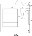
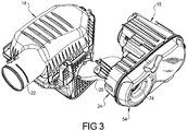
- vehicle 10 includes an engine 12 and an air-induction system 14 that provides air to the engine 12 via an air cleaner 18.
- the headlamp assembly 16 includes an illuminated air catcher passage 34 of the air-induction system 14.
- Conduits 20, 22 extend between the illuminated air catcher passage 34 and the air cleaner 18, and between the air cleaner 18 and the engine 12, respectively.
- the headlamp assembly 16 includes a housing 24 mounted to and at least partially received in a front end 28 ( Figure 1 ) of the vehicle 10.
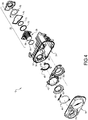
- the headlight assembly 16 includes a light generating headlight unit 50 and headlight reflector 52 mounted on a frame 42, a light generating running light unit 44 and running light reflector 46, and a light generating turn signal unit 48 supported generally within a housing cavity 30 covered by a translucent cap 54.
- Any or all of the light generating units 50, 44, and 48 comprise LED units.
- any or all of the light generating units 50, 44, and 48 comprise any of an incandescent, halogen or HID (high-intensity discharge) bulb.
- the cap 54 sealingly engages the housing 24 and encloses at least the light generating units 44 and 48 within the cavity 30 of the housing 24.
- the illustrated headlamp assembly 16 includes the air catcher passage 34 extending through the sealed cavity 30. In this manner, the airflow opening 74 and the passage 34 cooperate to form a continuous passageway that extends entirely through the sealed first headlamp assembly 16.
- the passageway passes through and includes airflow opening 74 through the translucent cap 54, an airflow opening 60 through the running light reflector 46, and an airflow opening 36 through a boss 32 disposed within the cavity 30 of the housing 24.
- an illuminated air catcher passage assembly 26 includes a front outer seal member 56, a light guide 58, rear outer seal member 70, front inner annular seal member 72, front inner plate seal member 76, light generating passage unit 78, and heat sink member 80. These components are assembled into an independent sub-assembly or unit 26 that is then coupled to the remainder of the headlight assembly 16. Threaded members 82 extend through openings 84 to hold the various components together as an independent sub-assembly 26. Alternatively, any or all of the components of the air catcher passage sub-assembly unit 26 are individually assembled into the headlamp assembly 16. In one such alternative, outer rear seal member 70 is individually mounted to the remainder of the headlamp assembly 16, separate from the remainder of the illuminated air catcher passage unit 26.
- the front outer seal member 56 of the illuminated air catcher passage assembly 26 engages a flanged surface 86 at a front of the boss 32, and the rear outer seal member 70 is mounted on a rear 88 of boss 32.
- the boss 32 surrounds the light guide 58 to prevent unwanted ambient light from passing into or through the light guide 58.
- one or both of the boss 32 and the light guide 58 includes a generally conical shaped inner surface 90 that increases in diameter as the illuminated air catcher passage extends from its front end 38 toward its rear end 40.
- the heat sink member 80 includes interiorly positioned fins 112 and an extending rear collar 114, around which the adjacent conduit 20 extends and to which the conduit 20 is coupled.
- heat generated by the LED's 106 is removed from the fins 112 and passes with the air flowing through the illuminated passage 36 through the conduits 20, 22 of the air-induction system 14 that provides air to the engine 12 via the air cleaner 18.
- the air passing through the air induction system 14 into the engine 12 is at least slightly preheated by the headlight assembly 16.
- the air catcher passage assembly 26 defines the illuminated air catcher passage 34 between the air induction opening 74 and the adjacent conduit 20.
- light guide 58 is a generally cylindrical tubular member with a flanged light receiving end 40.
- the tubular wall between the inner and outer surfaces 90 and 92, respectively, of the light guide 58 defines the illuminated air catcher passage 34.
- the inner surface 90 of the light guide 58 is smooth and comprises a clear hardcoat layer thereon to protect the surface 90 from potential damage or scratches from foreign objects aspirated into the passage 34.
- the clear hardcoat layer on the inner surface 90 is a UV curable hardcoat for forward automobile lighting, such as that sold under the tradename UVT610 and supplied commercially by Red Spot Paint & Varnish Company, Inc. of Evansville, Indiana.
- the outer surface 92 of the light guide 58 wall has a design 94 etched therein.
- the etched design 94 comprises repeating elements 96 extending along substantially the entire length of the light guide 58. As illustrated, the repeating elements 96 are radially spaced axially extending linear elements. Alternatively, the repeating elements 96 are a series of radial or circumferential rings axially spaced to extend along substantially the entire length of the light guide 58.
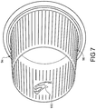
- the design 94 comprises a pictorial logo 100 ( Figs. 7 and 8 ).
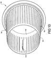
- the design comprises ordinary or stylized text such as a textual logo 98 ( Fig. 9 ), and/or a textual and pictorial logo combination 102 ( Fig 10 ).
- the air catcher light generating unit 78 comprises a printed circuit board 104 including an annular configuration of LED's 106 positioned within a sealed cavity 108 adjacent the rear end 40 of the light guide 58.
- a lens 110 is positioned between the LED's 106 and the light receiving or rear end 40 of the light guide 58.
- the lens 110 is interchangeable or selectively coated with florescent or phosphorescent materials to convert the outputted LED light to a selective color prior to entering the light guide 58, without the need to use different LED's for different colored illuminated light passages 34.
- the light guide 58 is made of a clear light guide material, such as a crystal lens grade polycarbonate material.
- the light from the LED's 106 enters the light guide 58 via the light receiving or rear end 40 thereof.
- the received LED light passes down the light guide 58 and is generally constrained by the light guide 58 between its inner surface 90 and its outer surface 92.
- the light is scattered by the design 94 engraved or etched on the outer surface 92, causing the design to glow visibly through the inner surface 90 of the light guide as illustrated best in Fig. 10 .
- it appears as if the inner surface 90 of the light guide 58 is glowing with the design 94, but the design positioned on the outer surface 92 where it is protected from damage by aspirated objects.
- the vehicle 10 may include both the driver's side headlamp assembly 16 and a passenger's side headlamp assembly 17, with a grille 19 disposed between the two headlamp assemblies 16, 17.
- the structure and function of the passenger's side headlamp assembly 17 is an identical mirror image assembly to the driver's side headlamp assembly 16. It will be appreciated, however, that both of the illuminated air catcher passage assemblies 26 of each of the headlamp assemblies 16, 17 are identical and interchangeable.
- the positioning of the air-inlet openings 74 in the headlamp assemblies 16, 17 at the front end 28 of the vehicle 10 provides the additional benefit of being at a high air-pressure zone of the vehicle 10 while the vehicle 10 is moving forward. This causes a ram-air effect that forces a larger volume of air over a given time period through the air-induction system 14 and into the engine 12, which further improves engine performance.
Landscapes
- Engineering & Computer Science (AREA)
- General Engineering & Computer Science (AREA)
- Mechanical Engineering (AREA)
- Chemical & Material Sciences (AREA)
- Combustion & Propulsion (AREA)
- Physics & Mathematics (AREA)
- Microelectronics & Electronic Packaging (AREA)
- Optics & Photonics (AREA)
- Transportation (AREA)
- Non-Portable Lighting Devices Or Systems Thereof (AREA)
- Lighting Device Outwards From Vehicle And Optical Signal (AREA)
- Arrangement Of Elements, Cooling, Sealing, Or The Like Of Lighting Devices (AREA)
Description
- The present disclosure relates to automotive headlamp assemblies including an air catcher passage.
-
US 9221331 B2 WO2015/167779 A1 discloses headlamp assemblies incorporating an air induction or catcher passage that feeds air to an internal combustion engine. Vehicle lighting has become an important focus in providing the desired visual and emotional impact of a vehicle's aesthetic design. - Sometimes the desired aesthetic impact necessitates minimizing the fact that the headlamp assembly includes an air induction passage. In such cases, the air induction passage is made to resemble a headlamp unit as much as possible. Sometimes, however, the desired aesthetic impact is best achieved by emphasizing the presence of an air induction passage, such as for an aggressive high performance vehicle design.
-
FR 3008777 A1 - According to the invention, a headlamp assembly for an automotive vehicle includes a headlamp housing mounted to a body of the vehicle. An airflow opening and an air catcher passage extend through the headlamp housing. A light guide coupled to the housing forms a portion of the air catcher passage extending from the airflow opening into an interior of the body of the vehicle. An outer surface of the light guide is etched with a light extracting visible design extending along a length of the air catcher passage. An LED light generating unit is positioned adjacent an end of the light guide to pass light from the light generating unit through the light guide that glows visibly the etched design with respect to the remainder of the surface.
- In another aspect of the present invention, the light guide and LED light generating unit form a sub-assembly mounted to the headlamp housing as an independent unit.
- In another aspect of the present invention, a hardcoat layer covers an interior surface of the light guide, opposite to the outer surface of the light guide.
- In another aspect of the present invention, the headlamp assembly includes a lens positioned between LED's of the light generating unit and the light guide, and the lens comprises a material to convert light emitted by the LED's to a selected color prior to entering the light guide.
- In another aspect of the present disclosure, the light guide comprises a tubular member defining a length of the air catcher passage and the headlight housing comprises a tubular boss surrounding the light guide.
- In another aspect of the present invention, a conduit provides fluid communication between the air catcher passage and an engine of the vehicle to provide air passing through the airflow passage to the engine.
- The present invention will become more fully understood from the detailed description and the accompanying drawings.
-
Fig. 1 is a front elevation view of a portion of a front end of a vehicle with one exemplary headlamp assembly in accordance with the present disclosure. -
Fig. 2 is a simplified schematic representation of the vehicle with the headlamp assembly ofFig. 1 . -
Fig. 3 is a perspective view of the headlamp assembly and air cleaner assembly ofFigs. 1 and2 . -
Fig. 4 is an exploded perspective view of the headlamp assembly ofFig. 1 . -
Fig. 5 is an enlarged exploded perspective view of the illuminated air catcher passage sub-assembly of the headlamp assembly ofFig. 1 . -
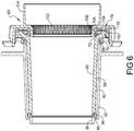
Fig. 6 is a cross-section view of the illuminated air catcher passage sub-assembly ofFig. 5 . -
Fig. 7 is a perspective view of the light guide of the illuminated air catcher passage sub-assembly ofFig. 5 . -
Fig. 8 is a perspective view of the exemplary headlamp assembly ofFig. 1 with a light guide etched with a pictorial graphic design. -
Fig. 9 is a perspective view of a light guide of the illuminated air catcher passage sub-assembly ofFig. 5 etched with an alternative textual graphic design. -
Fig. 10 is a perspective view of a light guide of the illuminated air catcher passage sub-assembly ofFig. 5 etched with an alternative combined textual and pictorial graphic design. - Further areas of applicability will become apparent from the description, claims and drawings, wherein like reference numerals refer to like features throughout the several views of the drawings. It should be understood that the detailed description, including disclosed embodiments and drawings referenced therein are merely exemplary in nature, intended for purposes of illustration only, and are not intended to limit the scope of the present disclosure.
-
Figs. 1-8 illustrate one exemplary embodiment of aheadlight assembly 16 for avehicle 10, including an illuminatedair catcher passage 34. Thevehicle 10 includes anengine 12 and an air-induction system 14 that provides air to theengine 12 via anair cleaner 18. Theheadlamp assembly 16 includes an illuminatedair catcher passage 34 of the air-induction system 14.Conduits air catcher passage 34 and theair cleaner 18, and between theair cleaner 18 and theengine 12, respectively. - The
headlamp assembly 16 includes ahousing 24 mounted to and at least partially received in a front end 28 (Figure 1 ) of thevehicle 10. Theheadlight assembly 16 includes a lightgenerating headlight unit 50 andheadlight reflector 52 mounted on a frame 42, a light generating runninglight unit 44 and runninglight reflector 46, and a light generatingturn signal unit 48 supported generally within ahousing cavity 30 covered by atranslucent cap 54. Any or all of thelight generating units light generating units - The
cap 54 sealingly engages thehousing 24 and encloses at least thelight generating units cavity 30 of thehousing 24. The illustratedheadlamp assembly 16 includes theair catcher passage 34 extending through the sealedcavity 30. In this manner, the airflow opening 74 and thepassage 34 cooperate to form a continuous passageway that extends entirely through the sealedfirst headlamp assembly 16. The passageway passes through and includes airflow opening 74 through thetranslucent cap 54, an airflow opening 60 through the runninglight reflector 46, and an airflow opening 36 through aboss 32 disposed within thecavity 30 of thehousing 24. - Referring to
Figs. 4 and5 , an illuminated aircatcher passage assembly 26 includes a frontouter seal member 56, alight guide 58, rearouter seal member 70, front innerannular seal member 72, front innerplate seal member 76, lightgenerating passage unit 78, andheat sink member 80. These components are assembled into an independent sub-assembly orunit 26 that is then coupled to the remainder of theheadlight assembly 16. Threadedmembers 82 extend throughopenings 84 to hold the various components together as anindependent sub-assembly 26. Alternatively, any or all of the components of the air catcherpassage sub-assembly unit 26 are individually assembled into theheadlamp assembly 16. In one such alternative, outerrear seal member 70 is individually mounted to the remainder of theheadlamp assembly 16, separate from the remainder of the illuminated aircatcher passage unit 26. - When assembled together, the front
outer seal member 56 of the illuminated aircatcher passage assembly 26 engages a flangedsurface 86 at a front of theboss 32, and the rearouter seal member 70 is mounted on a rear 88 ofboss 32. When sealed together, theboss 32 surrounds thelight guide 58 to prevent unwanted ambient light from passing into or through thelight guide 58. In an aspect, one or both of theboss 32 and thelight guide 58 includes a generally conical shapedinner surface 90 that increases in diameter as the illuminated air catcher passage extends from itsfront end 38 toward its rear end 40. - The
heat sink member 80 includes interiorly positionedfins 112 and an extendingrear collar 114, around which theadjacent conduit 20 extends and to which theconduit 20 is coupled. Thus, heat generated by the LED's 106 is removed from thefins 112 and passes with the air flowing through theilluminated passage 36 through theconduits induction system 14 that provides air to theengine 12 via theair cleaner 18. In an aspect, the air passing through theair induction system 14 into theengine 12 is at least slightly preheated by theheadlight assembly 16. - The air
catcher passage assembly 26 defines the illuminatedair catcher passage 34 between theair induction opening 74 and theadjacent conduit 20. In the illustrated example,light guide 58 is a generally cylindrical tubular member with a flanged light receiving end 40. The tubular wall between the inner andouter surfaces light guide 58 defines the illuminatedair catcher passage 34. - In an aspect, the
inner surface 90 of thelight guide 58 is smooth and comprises a clear hardcoat layer thereon to protect thesurface 90 from potential damage or scratches from foreign objects aspirated into thepassage 34. In a further aspect, the clear hardcoat layer on theinner surface 90 is a UV curable hardcoat for forward automobile lighting, such as that sold under the tradename UVT610 and supplied commercially by Red Spot Paint & Varnish Company, Inc. of Evansville, Indiana. - The
outer surface 92 of thelight guide 58 wall has adesign 94 etched therein. In an aspect, theetched design 94 comprises repeatingelements 96 extending along substantially the entire length of thelight guide 58. As illustrated, the repeatingelements 96 are radially spaced axially extending linear elements. Alternatively, the repeatingelements 96 are a series of radial or circumferential rings axially spaced to extend along substantially the entire length of thelight guide 58. - In an additional or alternative aspect, the
design 94 comprises a pictorial logo 100 (Figs. 7 and8 ). In further additional or alternative aspects, the design comprises ordinary or stylized text such as a textual logo 98 (Fig. 9 ), and/or a textual and pictorial logo combination 102 (Fig 10 ). - The air catcher
light generating unit 78 comprises a printedcircuit board 104 including an annular configuration of LED's 106 positioned within a sealedcavity 108 adjacent the rear end 40 of thelight guide 58. In an aspect, alens 110 is positioned between the LED's 106 and the light receiving or rear end 40 of thelight guide 58. In a further aspect, thelens 110 is interchangeable or selectively coated with florescent or phosphorescent materials to convert the outputted LED light to a selective color prior to entering thelight guide 58, without the need to use different LED's for different colored illuminatedlight passages 34. - The
light guide 58 is made of a clear light guide material, such as a crystal lens grade polycarbonate material. The light from the LED's 106 enters thelight guide 58 via the light receiving or rear end 40 thereof. The received LED light passes down thelight guide 58 and is generally constrained by thelight guide 58 between itsinner surface 90 and itsouter surface 92. The light, however, is scattered by thedesign 94 engraved or etched on theouter surface 92, causing the design to glow visibly through theinner surface 90 of the light guide as illustrated best inFig. 10 . Thus, it appears as if theinner surface 90 of thelight guide 58 is glowing with thedesign 94, but the design positioned on theouter surface 92 where it is protected from damage by aspirated objects. - As shown schematically in
Figure 2 , thevehicle 10 may include both the driver'sside headlamp assembly 16 and a passenger'sside headlamp assembly 17, with agrille 19 disposed between the twoheadlamp assemblies side headlamp assembly 17 is an identical mirror image assembly to the driver'sside headlamp assembly 16. It will be appreciated, however, that both of the illuminated aircatcher passage assemblies 26 of each of theheadlamp assemblies - The positioning of the air-
inlet openings 74 in theheadlamp assemblies front end 28 of thevehicle 10 provides the additional benefit of being at a high air-pressure zone of thevehicle 10 while thevehicle 10 is moving forward. This causes a ram-air effect that forces a larger volume of air over a given time period through the air-induction system 14 and into theengine 12, which further improves engine performance.
Claims (6)
- A headlamp assembly (16) for an automotive vehicle (10) comprising:a headlamp housing (24) to be mounted to a body of the vehicle (10) and including an airflow opening (74) and an air catcher passage (34) extending through the headlamp housing (24);characterised in thata light guide (58) coupled to the housing (24) forms a portion of the air catcher passage (34), said light guide (58) extending from the airflow opening (74) into an interior of the body of the vehicle (10);an LED light generating unit (78) is positioned adjacent an end of the light guide (58) to pass light from the light generating unit (78) through the light guide (58) wherein an outer surface (92) of the light guide (58) is etched with a light extracting visible design (94) extending along a length of the air catcher passage (34), the light guide being configured to glow visibly the design (94) with respect to the remainder of the surface when illuminated by the light emitted from the LED light generating unit (78).
- The headlamp assembly according to claim 1, wherein the light guide (58) and LED light generating unit (78) form a sub-assembly mounted to the headlamp housing (24) as an independent unit.
- The headlamp assembly according to any of claims 1 or 2, further comprising a hardcoat layer covering an interior surface (90) of the light guide (58), opposite to the outer surface (92) of the light guide (58).
- The headlamp assembly according to any of claims 1-3, further comprising a lens (110) positioned between LED's (106) of the light generating unit (78) and the light guide (58), wherein the lens (110) comprises a material to convert light emitted by the LED's (106) to a selected color prior to entering the light guide (58).
- The headlamp assembly according to any of claims 1 -4, wherein the light guide (58) comprises a tubular member defining a length of the air catcher passage (34) and the headlight housing (24) comprises a tubular boss (32) surrounding the light guide (58).
- The headlamp assembly according to any of claims 1-5, further comprising a conduit (20, 22) providing fluid communication between the air catcher passage (34) and an engine (12) of the vehicle (10) to provide air passing through the airflow passage (34) to the engine (12).
Applications Claiming Priority (2)
| Application Number | Priority Date | Filing Date | Title |
|---|---|---|---|
| US15/141,107 US10160375B2 (en) | 2016-04-28 | 2016-04-28 | Illuminated air catcher passage |
| PCT/US2017/025969 WO2017189192A1 (en) | 2016-04-28 | 2017-04-04 | Illuminated air catcher passage |
Publications (2)
| Publication Number | Publication Date |
|---|---|
| EP3448721A1 EP3448721A1 (en) | 2019-03-06 |
| EP3448721B1 true EP3448721B1 (en) | 2020-07-15 |
Family
ID=58578984
Family Applications (1)
| Application Number | Title | Priority Date | Filing Date |
|---|---|---|---|
| EP17718451.2A Active EP3448721B1 (en) | 2016-04-28 | 2017-04-04 | Illuminated air catcher passage |
Country Status (5)
| Country | Link |
|---|---|
| US (1) | US10160375B2 (en) |
| EP (1) | EP3448721B1 (en) |
| CN (1) | CN109070789B (en) |
| CA (1) | CA3018565A1 (en) |
| WO (1) | WO2017189192A1 (en) |
Families Citing this family (3)
| Publication number | Priority date | Publication date | Assignee | Title |
|---|---|---|---|---|
| US20190249839A1 (en) * | 2018-02-14 | 2019-08-15 | Varroc Lighting Systems, s.r.o. | Laser-etched light guide assembly |
| US12180916B2 (en) * | 2020-02-09 | 2024-12-31 | Velossa Tech Engineering Inc. | Interchangeable intake manifold assemblies |
| DE102024114213A1 (en) * | 2024-05-22 | 2025-11-27 | Dr. Ing. H.C. F. Porsche Aktiengesellschaft | Method for manufacturing a grid for an air opening of a motor vehicle body, grid assembly of an air opening of a motor vehicle body and motor vehicle body with a grid assembly |
Family Cites Families (13)
| Publication number | Priority date | Publication date | Assignee | Title |
|---|---|---|---|---|
| US4120024A (en) | 1976-10-18 | 1978-10-10 | Julian Borisovich Aizenberg | Lighting installation |
| FR2698055B1 (en) | 1992-11-18 | 1995-02-03 | Peugeot | Ventilated optical unit, especially for motor vehicles. |
| DE10137605A1 (en) | 2001-08-01 | 2003-02-27 | Hella Kg Hueck & Co | Light for vehicles |
| DE102004025624A1 (en) | 2004-05-25 | 2005-12-15 | Hella Kgaa Hueck & Co. | Headlamp with heat exchanger for cooling bulbs |
| US7841756B2 (en) | 2008-01-31 | 2010-11-30 | Honda Motor Co., Ltd. | Vehicle lamp assembly |
| US8132947B2 (en) * | 2009-08-27 | 2012-03-13 | Jen Shieh Shih | Vehicle head light device |
| US20130051046A1 (en) | 2011-08-25 | 2013-02-28 | Grang Fair Industrial Co., Ltd. | Led aperture of automobile lamp |
| CN102616173A (en) * | 2012-04-20 | 2012-08-01 | 吉林省启萌工业产品设计有限公司 | Automobile lamp based on light guide multi-direction light emitting and light curtain technology |
| FR3008777B1 (en) * | 2013-07-22 | 2017-12-29 | Renault Sas | LIGHTING SYSTEM, IN PARTICULAR FOR A MOTOR VEHICLE LIGHTING BODY, WITH INTEGRATED LEDS |
| DE102013216869B4 (en) * | 2013-08-23 | 2019-06-19 | Bayerische Motoren Werke Aktiengesellschaft | Cooling device for a headlight of a motor vehicle, in particular for a laser headlight |
| US9221331B2 (en) * | 2014-05-01 | 2015-12-29 | Fca Us Llc | Headlamp and air-induction system |
| GB2531545A (en) | 2014-10-21 | 2016-04-27 | Daimler Ag | Headlight assembly as well as hood assembly for a commercial vehicle |
| CN104696846A (en) * | 2015-03-04 | 2015-06-10 | 上海小糸车灯有限公司 | LED optical structure for car lamps |
-
2016
- 2016-04-28 US US15/141,107 patent/US10160375B2/en active Active
-
2017
- 2017-04-04 CN CN201780025771.8A patent/CN109070789B/en active Active
- 2017-04-04 WO PCT/US2017/025969 patent/WO2017189192A1/en not_active Ceased
- 2017-04-04 EP EP17718451.2A patent/EP3448721B1/en active Active
- 2017-04-04 CA CA3018565A patent/CA3018565A1/en not_active Abandoned
Non-Patent Citations (1)
| Title |
|---|
| None * |
Also Published As
| Publication number | Publication date |
|---|---|
| CN109070789B (en) | 2022-03-22 |
| CN109070789A (en) | 2018-12-21 |
| US20170313236A1 (en) | 2017-11-02 |
| US10160375B2 (en) | 2018-12-25 |
| EP3448721A1 (en) | 2019-03-06 |
| CA3018565A1 (en) | 2017-11-02 |
| WO2017189192A1 (en) | 2017-11-02 |
Similar Documents
| Publication | Publication Date | Title |
|---|---|---|
| CN103010086B (en) | Vehicular illumination device | |
| CN101505997B (en) | steering wheel device | |
| US6851843B2 (en) | Light assembly, especially signal light, for motor vehicles | |
| EP2628627A1 (en) | Micro perforated leather with a lighting element | |
| US11499690B2 (en) | Automotive lighting and/or signaling device | |
| US10160375B2 (en) | Illuminated air catcher passage | |
| CN108930954B (en) | Illuminated vehicle assembly and method of illumination | |
| EP3463980B1 (en) | A lamp assembly for a vehicle | |
| US10502390B1 (en) | Vehicle lamp assembly having a bezek, lens and lamp housing with a micro mesh of holes in a side wall | |
| US7588358B1 (en) | Single LED and lens assembly | |
| US20020034079A1 (en) | Reading lamp for a vehicle interior | |
| US20020041491A1 (en) | Automotive meter with internal illumination structure | |
| EP3812185B1 (en) | Air diffuser for motor vehicles | |
| US10259376B2 (en) | Vehicle exterior lighting systems | |
| US9221331B2 (en) | Headlamp and air-induction system | |
| EP3559549B1 (en) | Homogenous led vehicle lamp | |
| CN113329912A (en) | Lighting device for vehicle ceiling lamp | |
| CN104456358A (en) | Automotive interior LED lamp | |
| JP6820170B2 (en) | Vehicle lighting | |
| US20120326465A1 (en) | Sunshade assembly with light | |
| US20060062012A1 (en) | Vehicle lamp with two lighting circles | |
| EP1270307B1 (en) | Automotive meter with internal illumination structure | |
| US9341339B2 (en) | Lightng device having a ventilated reflector housing for motor vehicle lamp | |
| CN103292233A (en) | Lamp for vehicle | |
| US20190249839A1 (en) | Laser-etched light guide assembly |
Legal Events
| Date | Code | Title | Description |
|---|---|---|---|
| STAA | Information on the status of an ep patent application or granted ep patent |
Free format text: STATUS: UNKNOWN |
|
| STAA | Information on the status of an ep patent application or granted ep patent |
Free format text: STATUS: THE INTERNATIONAL PUBLICATION HAS BEEN MADE |
|
| PUAI | Public reference made under article 153(3) epc to a published international application that has entered the european phase |
Free format text: ORIGINAL CODE: 0009012 |
|
| STAA | Information on the status of an ep patent application or granted ep patent |
Free format text: STATUS: REQUEST FOR EXAMINATION WAS MADE |
|
| 17P | Request for examination filed |
Effective date: 20181121 |
|
| AK | Designated contracting states |
Kind code of ref document: A1 Designated state(s): AL AT BE BG CH CY CZ DE DK EE ES FI FR GB GR HR HU IE IS IT LI LT LU LV MC MK MT NL NO PL PT RO RS SE SI SK SM TR |
|
| AX | Request for extension of the european patent |
Extension state: BA ME |
|
| DAV | Request for validation of the european patent (deleted) | ||
| DAX | Request for extension of the european patent (deleted) | ||
| RIC1 | Information provided on ipc code assigned before grant |
Ipc: F21S 43/50 20180101ALI20191216BHEP Ipc: B60Q 1/26 20060101ALI20191216BHEP Ipc: B60Q 1/00 20060101AFI20191216BHEP Ipc: F21S 43/245 20180101ALI20191216BHEP Ipc: F21S 45/43 20180101ALI20191216BHEP Ipc: F21S 43/241 20180101ALI20191216BHEP Ipc: B60K 13/02 20060101ALI20191216BHEP Ipc: F21S 43/27 20180101ALI20191216BHEP Ipc: F02M 35/10 20060101ALI20191216BHEP Ipc: B60R 13/00 20060101ALI20191216BHEP Ipc: F21S 43/14 20180101ALI20191216BHEP Ipc: F21S 43/237 20180101ALI20191216BHEP |
|
| GRAP | Despatch of communication of intention to grant a patent |
Free format text: ORIGINAL CODE: EPIDOSNIGR1 |
|
| STAA | Information on the status of an ep patent application or granted ep patent |
Free format text: STATUS: GRANT OF PATENT IS INTENDED |
|
| INTG | Intention to grant announced |
Effective date: 20200130 |
|
| GRAS | Grant fee paid |
Free format text: ORIGINAL CODE: EPIDOSNIGR3 |
|
| GRAA | (expected) grant |
Free format text: ORIGINAL CODE: 0009210 |
|
| STAA | Information on the status of an ep patent application or granted ep patent |
Free format text: STATUS: THE PATENT HAS BEEN GRANTED |
|
| AK | Designated contracting states |
Kind code of ref document: B1 Designated state(s): AL AT BE BG CH CY CZ DE DK EE ES FI FR GB GR HR HU IE IS IT LI LT LU LV MC MK MT NL NO PL PT RO RS SE SI SK SM TR |
|
| REG | Reference to a national code |
Ref country code: CH Ref legal event code: EP Ref country code: GB Ref legal event code: FG4D |
|
| REG | Reference to a national code |
Ref country code: IE Ref legal event code: FG4D |
|
| REG | Reference to a national code |
Ref country code: DE Ref legal event code: R096 Ref document number: 602017019801 Country of ref document: DE |
|
| REG | Reference to a national code |
Ref country code: AT Ref legal event code: REF Ref document number: 1290672 Country of ref document: AT Kind code of ref document: T Effective date: 20200815 |
|
| REG | Reference to a national code |
Ref country code: LT Ref legal event code: MG4D |
|
| REG | Reference to a national code |
Ref country code: AT Ref legal event code: MK05 Ref document number: 1290672 Country of ref document: AT Kind code of ref document: T Effective date: 20200715 |
|
| REG | Reference to a national code |
Ref country code: NL Ref legal event code: MP Effective date: 20200715 |
|
| PG25 | Lapsed in a contracting state [announced via postgrant information from national office to epo] |
Ref country code: ES Free format text: LAPSE BECAUSE OF FAILURE TO SUBMIT A TRANSLATION OF THE DESCRIPTION OR TO PAY THE FEE WITHIN THE PRESCRIBED TIME-LIMIT Effective date: 20200715 Ref country code: LT Free format text: LAPSE BECAUSE OF FAILURE TO SUBMIT A TRANSLATION OF THE DESCRIPTION OR TO PAY THE FEE WITHIN THE PRESCRIBED TIME-LIMIT Effective date: 20200715 Ref country code: BG Free format text: LAPSE BECAUSE OF FAILURE TO SUBMIT A TRANSLATION OF THE DESCRIPTION OR TO PAY THE FEE WITHIN THE PRESCRIBED TIME-LIMIT Effective date: 20201015 Ref country code: PT Free format text: LAPSE BECAUSE OF FAILURE TO SUBMIT A TRANSLATION OF THE DESCRIPTION OR TO PAY THE FEE WITHIN THE PRESCRIBED TIME-LIMIT Effective date: 20201116 Ref country code: AT Free format text: LAPSE BECAUSE OF FAILURE TO SUBMIT A TRANSLATION OF THE DESCRIPTION OR TO PAY THE FEE WITHIN THE PRESCRIBED TIME-LIMIT Effective date: 20200715 Ref country code: NO Free format text: LAPSE BECAUSE OF FAILURE TO SUBMIT A TRANSLATION OF THE DESCRIPTION OR TO PAY THE FEE WITHIN THE PRESCRIBED TIME-LIMIT Effective date: 20201015 Ref country code: HR Free format text: LAPSE BECAUSE OF FAILURE TO SUBMIT A TRANSLATION OF THE DESCRIPTION OR TO PAY THE FEE WITHIN THE PRESCRIBED TIME-LIMIT Effective date: 20200715 Ref country code: FI Free format text: LAPSE BECAUSE OF FAILURE TO SUBMIT A TRANSLATION OF THE DESCRIPTION OR TO PAY THE FEE WITHIN THE PRESCRIBED TIME-LIMIT Effective date: 20200715 Ref country code: GR Free format text: LAPSE BECAUSE OF FAILURE TO SUBMIT A TRANSLATION OF THE DESCRIPTION OR TO PAY THE FEE WITHIN THE PRESCRIBED TIME-LIMIT Effective date: 20201016 Ref country code: SE Free format text: LAPSE BECAUSE OF FAILURE TO SUBMIT A TRANSLATION OF THE DESCRIPTION OR TO PAY THE FEE WITHIN THE PRESCRIBED TIME-LIMIT Effective date: 20200715 |
|
| PG25 | Lapsed in a contracting state [announced via postgrant information from national office to epo] |
Ref country code: RS Free format text: LAPSE BECAUSE OF FAILURE TO SUBMIT A TRANSLATION OF THE DESCRIPTION OR TO PAY THE FEE WITHIN THE PRESCRIBED TIME-LIMIT Effective date: 20200715 Ref country code: LV Free format text: LAPSE BECAUSE OF FAILURE TO SUBMIT A TRANSLATION OF THE DESCRIPTION OR TO PAY THE FEE WITHIN THE PRESCRIBED TIME-LIMIT Effective date: 20200715 Ref country code: PL Free format text: LAPSE BECAUSE OF FAILURE TO SUBMIT A TRANSLATION OF THE DESCRIPTION OR TO PAY THE FEE WITHIN THE PRESCRIBED TIME-LIMIT Effective date: 20200715 Ref country code: IS Free format text: LAPSE BECAUSE OF FAILURE TO SUBMIT A TRANSLATION OF THE DESCRIPTION OR TO PAY THE FEE WITHIN THE PRESCRIBED TIME-LIMIT Effective date: 20201115 |
|
| PG25 | Lapsed in a contracting state [announced via postgrant information from national office to epo] |
Ref country code: NL Free format text: LAPSE BECAUSE OF FAILURE TO SUBMIT A TRANSLATION OF THE DESCRIPTION OR TO PAY THE FEE WITHIN THE PRESCRIBED TIME-LIMIT Effective date: 20200715 |
|
| REG | Reference to a national code |
Ref country code: DE Ref legal event code: R097 Ref document number: 602017019801 Country of ref document: DE |
|
| PG25 | Lapsed in a contracting state [announced via postgrant information from national office to epo] |
Ref country code: RO Free format text: LAPSE BECAUSE OF FAILURE TO SUBMIT A TRANSLATION OF THE DESCRIPTION OR TO PAY THE FEE WITHIN THE PRESCRIBED TIME-LIMIT Effective date: 20200715 Ref country code: CZ Free format text: LAPSE BECAUSE OF FAILURE TO SUBMIT A TRANSLATION OF THE DESCRIPTION OR TO PAY THE FEE WITHIN THE PRESCRIBED TIME-LIMIT Effective date: 20200715 Ref country code: DK Free format text: LAPSE BECAUSE OF FAILURE TO SUBMIT A TRANSLATION OF THE DESCRIPTION OR TO PAY THE FEE WITHIN THE PRESCRIBED TIME-LIMIT Effective date: 20200715 Ref country code: EE Free format text: LAPSE BECAUSE OF FAILURE TO SUBMIT A TRANSLATION OF THE DESCRIPTION OR TO PAY THE FEE WITHIN THE PRESCRIBED TIME-LIMIT Effective date: 20200715 Ref country code: SM Free format text: LAPSE BECAUSE OF FAILURE TO SUBMIT A TRANSLATION OF THE DESCRIPTION OR TO PAY THE FEE WITHIN THE PRESCRIBED TIME-LIMIT Effective date: 20200715 |
|
| PLBE | No opposition filed within time limit |
Free format text: ORIGINAL CODE: 0009261 |
|
| STAA | Information on the status of an ep patent application or granted ep patent |
Free format text: STATUS: NO OPPOSITION FILED WITHIN TIME LIMIT |
|
| PG25 | Lapsed in a contracting state [announced via postgrant information from national office to epo] |
Ref country code: AL Free format text: LAPSE BECAUSE OF FAILURE TO SUBMIT A TRANSLATION OF THE DESCRIPTION OR TO PAY THE FEE WITHIN THE PRESCRIBED TIME-LIMIT Effective date: 20200715 |
|
| 26N | No opposition filed |
Effective date: 20210416 |
|
| PG25 | Lapsed in a contracting state [announced via postgrant information from national office to epo] |
Ref country code: SK Free format text: LAPSE BECAUSE OF FAILURE TO SUBMIT A TRANSLATION OF THE DESCRIPTION OR TO PAY THE FEE WITHIN THE PRESCRIBED TIME-LIMIT Effective date: 20200715 |
|
| PG25 | Lapsed in a contracting state [announced via postgrant information from national office to epo] |
Ref country code: SI Free format text: LAPSE BECAUSE OF FAILURE TO SUBMIT A TRANSLATION OF THE DESCRIPTION OR TO PAY THE FEE WITHIN THE PRESCRIBED TIME-LIMIT Effective date: 20200715 |
|
| PG25 | Lapsed in a contracting state [announced via postgrant information from national office to epo] |
Ref country code: MC Free format text: LAPSE BECAUSE OF FAILURE TO SUBMIT A TRANSLATION OF THE DESCRIPTION OR TO PAY THE FEE WITHIN THE PRESCRIBED TIME-LIMIT Effective date: 20200715 |
|
| PG25 | Lapsed in a contracting state [announced via postgrant information from national office to epo] |
Ref country code: LU Free format text: LAPSE BECAUSE OF NON-PAYMENT OF DUE FEES Effective date: 20210404 |
|
| REG | Reference to a national code |
Ref country code: BE Ref legal event code: MM Effective date: 20210430 |
|
| PG25 | Lapsed in a contracting state [announced via postgrant information from national office to epo] |
Ref country code: CH Free format text: LAPSE BECAUSE OF NON-PAYMENT OF DUE FEES Effective date: 20210430 Ref country code: LI Free format text: LAPSE BECAUSE OF NON-PAYMENT OF DUE FEES Effective date: 20210430 |
|
| PG25 | Lapsed in a contracting state [announced via postgrant information from national office to epo] |
Ref country code: IE Free format text: LAPSE BECAUSE OF NON-PAYMENT OF DUE FEES Effective date: 20210404 |
|
| PG25 | Lapsed in a contracting state [announced via postgrant information from national office to epo] |
Ref country code: IS Free format text: LAPSE BECAUSE OF FAILURE TO SUBMIT A TRANSLATION OF THE DESCRIPTION OR TO PAY THE FEE WITHIN THE PRESCRIBED TIME-LIMIT Effective date: 20201115 |
|
| PG25 | Lapsed in a contracting state [announced via postgrant information from national office to epo] |
Ref country code: BE Free format text: LAPSE BECAUSE OF NON-PAYMENT OF DUE FEES Effective date: 20210430 |
|
| PG25 | Lapsed in a contracting state [announced via postgrant information from national office to epo] |
Ref country code: CY Free format text: LAPSE BECAUSE OF FAILURE TO SUBMIT A TRANSLATION OF THE DESCRIPTION OR TO PAY THE FEE WITHIN THE PRESCRIBED TIME-LIMIT Effective date: 20200715 |
|
| PG25 | Lapsed in a contracting state [announced via postgrant information from national office to epo] |
Ref country code: HU Free format text: LAPSE BECAUSE OF FAILURE TO SUBMIT A TRANSLATION OF THE DESCRIPTION OR TO PAY THE FEE WITHIN THE PRESCRIBED TIME-LIMIT; INVALID AB INITIO Effective date: 20170404 |
|
| PG25 | Lapsed in a contracting state [announced via postgrant information from national office to epo] |
Ref country code: MK Free format text: LAPSE BECAUSE OF FAILURE TO SUBMIT A TRANSLATION OF THE DESCRIPTION OR TO PAY THE FEE WITHIN THE PRESCRIBED TIME-LIMIT Effective date: 20200715 |
|
| PG25 | Lapsed in a contracting state [announced via postgrant information from national office to epo] |
Ref country code: TR Free format text: LAPSE BECAUSE OF FAILURE TO SUBMIT A TRANSLATION OF THE DESCRIPTION OR TO PAY THE FEE WITHIN THE PRESCRIBED TIME-LIMIT Effective date: 20200715 |
|
| PG25 | Lapsed in a contracting state [announced via postgrant information from national office to epo] |
Ref country code: MT Free format text: LAPSE BECAUSE OF FAILURE TO SUBMIT A TRANSLATION OF THE DESCRIPTION OR TO PAY THE FEE WITHIN THE PRESCRIBED TIME-LIMIT Effective date: 20200715 |
|
| PGFP | Annual fee paid to national office [announced via postgrant information from national office to epo] |
Ref country code: DE Payment date: 20250429 Year of fee payment: 9 |
|
| PGFP | Annual fee paid to national office [announced via postgrant information from national office to epo] |
Ref country code: GB Payment date: 20250428 Year of fee payment: 9 |
|
| PGFP | Annual fee paid to national office [announced via postgrant information from national office to epo] |
Ref country code: IT Payment date: 20250422 Year of fee payment: 9 |
|
| PGFP | Annual fee paid to national office [announced via postgrant information from national office to epo] |
Ref country code: FR Payment date: 20250425 Year of fee payment: 9 |