EP3448289B1 - Inflatable bone tamp with flow control - Google Patents
Inflatable bone tamp with flow control Download PDFInfo
- Publication number
- EP3448289B1 EP3448289B1 EP17790239.2A EP17790239A EP3448289B1 EP 3448289 B1 EP3448289 B1 EP 3448289B1 EP 17790239 A EP17790239 A EP 17790239A EP 3448289 B1 EP3448289 B1 EP 3448289B1
- Authority
- EP
- European Patent Office
- Prior art keywords
- balloon
- flow controllers
- shaft
- coupled
- flow
- Prior art date
- Legal status (The legal status is an assumption and is not a legal conclusion. Google has not performed a legal analysis and makes no representation as to the accuracy of the status listed.)
- Not-in-force
Links
Images








Classifications
-
- A—HUMAN NECESSITIES
- A61—MEDICAL OR VETERINARY SCIENCE; HYGIENE
- A61B—DIAGNOSIS; SURGERY; IDENTIFICATION
- A61B17/00—Surgical instruments, devices or methods
- A61B17/56—Surgical instruments or methods for treatment of bones or joints; Devices specially adapted therefor
- A61B17/58—Surgical instruments or methods for treatment of bones or joints; Devices specially adapted therefor for osteosynthesis, e.g. bone plates, screws or setting implements
- A61B17/88—Osteosynthesis instruments; Methods or means for implanting or extracting internal or external fixation devices
- A61B17/885—Tools for expanding or compacting bones or discs or cavities therein
- A61B17/8852—Tools for expanding or compacting bones or discs or cavities therein capable of being assembled or enlarged, or changing shape, inside the bone or disc
- A61B17/8855—Tools for expanding or compacting bones or discs or cavities therein capable of being assembled or enlarged, or changing shape, inside the bone or disc inflatable, e.g. kyphoplasty balloons
-
- A—HUMAN NECESSITIES
- A61—MEDICAL OR VETERINARY SCIENCE; HYGIENE
- A61B—DIAGNOSIS; SURGERY; IDENTIFICATION
- A61B17/00—Surgical instruments, devices or methods
- A61B17/56—Surgical instruments or methods for treatment of bones or joints; Devices specially adapted therefor
- A61B17/58—Surgical instruments or methods for treatment of bones or joints; Devices specially adapted therefor for osteosynthesis, e.g. bone plates, screws or setting implements
- A61B17/88—Osteosynthesis instruments; Methods or means for implanting or extracting internal or external fixation devices
- A61B17/8802—Equipment for handling bone cement or other fluid fillers
- A61B17/8805—Equipment for handling bone cement or other fluid fillers for introducing fluid filler into bone or extracting it
- A61B17/8827—Equipment for handling bone cement or other fluid fillers for introducing fluid filler into bone or extracting it with filtering, degassing, venting or pressure relief means
-
- A—HUMAN NECESSITIES
- A61—MEDICAL OR VETERINARY SCIENCE; HYGIENE
- A61B—DIAGNOSIS; SURGERY; IDENTIFICATION
- A61B17/00—Surgical instruments, devices or methods
- A61B17/56—Surgical instruments or methods for treatment of bones or joints; Devices specially adapted therefor
- A61B17/58—Surgical instruments or methods for treatment of bones or joints; Devices specially adapted therefor for osteosynthesis, e.g. bone plates, screws or setting implements
- A61B17/88—Osteosynthesis instruments; Methods or means for implanting or extracting internal or external fixation devices
- A61B17/885—Tools for expanding or compacting bones or discs or cavities therein
Definitions
- the present disclosure generally relates to medical devices for the treatment of bone disorders, and more particularly to devices for treating spina disorders, such as, for example, vertebral compression fractures.
- kyphoplasty is a minimally invasive procedure that is used to treat spinal fractures, such as, for example, vertebral compression fractures by inserting one or more balloons, such as, for example, compliant balloons inside a fractured vertebral body.
- the balloon or balloons are inflated within the fractured vertebral body such that the cancellous bone of the vertebral body is pushed towards cortical walls of the vertebral body to form a cavity within the vertebral body.
- the cavity is then at least partially filled with a material, such as, for example, bone cement.
- US2014316411A1 discloses systems and methods of using expandable elements inserted into a bone, such as the distal radius, to provide for minimally invasive reduction and fixation of fractures.
- the disclosed device comprises a shaft, a balloon and a flow controller.
- the devices comprise an inflatable bone tamp (IBT) comprising a shaft.
- a balloon is coupled to the shaft such that a material can flow through the shaft and into the balloon to inflate the balloon.
- the IBT comprises a shaft extending along a central longitudinal axis between opposite proximal and distal portions;
- the IBT comprises a connector that is coupled to the shaft.
- the connector is a V-connector.
- the flow controller is coupled to the connector.
- the flow controller is mounted in the connector.
- the balloon can be coupled to the inner shaft and/or the outer shaft.
- the flow controller is positioned between the outer shaft and the inner shaft.
- the flow controller can be coupled to the shaft between the proximal portion and the distal portion that controls the flow of the material through the shaft and into the balloon.
- the flow controllers are mounted in the space between the inner shaft and the outer shaft.
- the flow controller is coupled to the outer shaft.
- the flow controller is mounted in the outer shaft.
- the flow controller is coupled to the inner shaft.
- the flow controller is mounted in the inner shaft.
- the flow controller is crimped onto the inner shaft. In some embodiments, the flow controller is crimped onto the outer shaft. In some embodiments, the flow controller is crimped onto the outer shaft and comprises a plurality of flow controllers that act as flow chokes. There are embodiments where the flow controller comprises a spongiform structure.
- balloon catheter 40 can be fabricated from biologically acceptable materials suitable for medical applications, including metals, synthetic polymers, ceramics and bone material and/or their composites, depending on the particular application and/or preference of a medical practitioner.
- the components of balloon catheter 40 can be fabricated from materials such as stainless steel alloys, commercially pure titanium, titanium alloys, Grade 5 titanium, super-elastic titanium alloys, cobalt-chrome alloys, stainless steel alloys, superelastic metallic alloys (e.g., Nitinol, super elasto-plastic metals, such as GUM METAL ® manufactured by Toyota Material Incorporated of Japan), ceramics and composites thereof such as calcium phosphate (e.g., SKELITE TM manufactured by Biologix Inc.), thermoplastics such as polyaryletherketone (PAEK) including polyetheretherketone (PEEK), polyetherketoneketone (PEKK) and polyetherketone (PEK), carbon-PEEK composites, PEEK-BaSO4 polymeric rubbers, polyethylene terephthalate (PET), fabric, silicone, polyurethane, silicone-polyurethane copolymers, polymeric rubbers, polyolefin rubbers,
- PEEK polyaryl
- Various components of balloon catheter 40 may have material composites, including the above materials, to achieve various desired characteristics such as strength, rigidity, elasticity, compliance, biomechanical performance, durability and radiolucency or imaging preference.
- the components of balloon catheter 40 individually or collectively, may also be fabricated from a heterogeneous material such as a combination of two or more of the above-described materials.
- the components of balloon catheter 40 may be monolithically formed, integrally connected or comprise fastening elements and/or instruments, as described herein.
- Balloon catheter 40 comprises an outer shaft or cylindrical portion 42 and a balloon 44 coupled to cylindrical portion 42.
- a proximal portion 44a of balloon 44 is coupled to cylindrical portion 42 and an opposite distal portion 44b of balloon 44 is spaced apart from or nonadjacent to the cylindrical portion 42.
- Cylindrical portion 42 is hollow and defines a passageway 46.
- passageway 46 is in communication with an internal chamber 48 of balloon 44.
- passageway 46 is configured to form passage of a material to move balloon 44 from an unexpanded configuration, such as, for example, an uninflated configuration to an expanded configuration, such as, for example, an inflated configuration.
- a material may be moved through passageway 46 and into chamber 48 to move balloon 44 from the uninflated configuration to the inflated configuration.
- balloon 44 When balloon 44 is in the inflated configuration, balloon 44 has a maximum diameter that is greater than the maximum diameter of balloon 44 when balloon 44 is in the uninflated configuration.
- the material is a liquid, such as, for example, a contrast solution, saline or water.
- passageway 46 is configured for passage of a material to move balloon 44 from the inflated configuration to the uninflated configuration, as discussed herein. That is, the material moves through passageway 46 to allow balloon 44 to deflate.
- cylindrical portion 42 is a hollow shaft or tube.
- cylindrical portion 42 is flexible to allow cylindrical portion 42 to bend as cylindrical portion 42 is navigated through a patient's anatomy.
- cylindrical portion 42 may be flexible to allow cylindrical portion 42 to be navigated along a curved path created by a medical practitioner in order to position balloon 44 at, in or near a target location or treatment zone, such as, for example, within a vertebral body.
- cylindrical portion 42 can be bent without breaking cylindrical portion 42.
- cylindrical portion 42 is rigid such that cylindrical portion 42 cannot be bent without cylindrical portion 42 breaking.
- cylindrical portion 42 may be rigid to provide strength to cylindrical portion 42 in applications wherein balloon catheter 40 is navigated along a straight path created by a medical practitioner in order to position balloon 44 at, in or near a target location or treatment zone, such as, for example, a space within a vertebral body.
- balloon 44 is made from a resilient biocompatible material.
- balloon 44 is a compliant balloon that resists stretching.
- balloon 44 comprises polyolefin copolymer (POC), Polyurethane, Nylon.
- POC polyolefin copolymer
- balloon 44 is a non-compliant or semi-compliant balloon that stretches, at least to some degree.
- balloon 44 comprises polyethylene terapthelate (PET).
- PET polyethylene terapthelate
- balloon 44 can have various cross section configurations when balloon 44 is in the inflated configuration, such as, for example, oval, oblong, triangular, rectangular, square, polygonal, irregular, uniform, non-uniform, variable, tubular and/or tapered.
- an outer surface of balloon 44 may have various surface configurations, such as, for example, smooth and/or surface configurations to enhance fixation with tissue, such as, for example, rough, arcuate, undulating, porous, semi-porous, dimpled, polished and/or textured.
- Balloon 44 can be a single or a multi-layered balloon, where each balloon layer has the same diameter and/or wall thickness, is comprised of the same material or materials having substantially identical mechanical properties, and has the same degree of molecular orientation in the body portion of the balloon. It will be apparent that in some situations it will be desirable to have some balloon layers having different thicknesses, materials, and/or degree of molecular orientations upon deflation, while at the same time having equivalent size, mechanical properties, and/or orientation upon inflation.
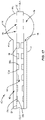
- Balloon catheter 40 comprises a plurality of flow controllers 50.
- flow controllers 50 are positioned within cylindrical portion 42.
- flow controllers 50 are configured to control the flow of the material through passageway 46 as the material travels through passageway 46.
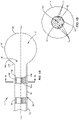
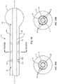
- flow controllers 50 directly engage an inner surface 52 of cylindrical portion 42 such that a central portion of passageway 46 is unobstructed along a central longitudinal axis CLA defined by cylindrical portion 42, as shown in FIGS. 1, 2 and 3 .
- flow controllers 50 directly engage inner surface 52 of cylindrical portion 42 such that at least one of flow controllers 50 block and/or obstruct the central portion of passageway 46 along central longitudinal axis CLA, as shown in FIGS. 1A and 1B .
- flow controllers 50 comprise a material, such as, for example, one of the materials discussed herein. In some embodiments, flow controllers 50 comprise a non-porous material. Flow controller 50 is comprised of discrete bands concentric to central longitudinal axis CLA or discrete strips that extend parallel to central longitudinal axis CLA, as shown in FIGS. 1-3 . In some embodiments, flow controllers 50 comprise a porous material that may be a lattice-like or spongiform structure. In some embodiments, flow controllers 50 comprise a foam material, such as, for example, an open cell foam material or spongiform material/structure.
- the open cell foam material or spongiform material/structure comprises one or a plurality of pores 54, as shown in FIG. 1B .
- at least one of pores 54 extends through opposite proximal and distal surfaces 50a, 50b a respective flow controller 50.
- at least one of pores 54 extends through one of proximal and distal surfaces 50a, 50b without extending through the other one of proximal and distal surfaces 50a, 50b.
- at least one of pores 54 is in communication with at least another one of pores 54.
- pores 54 are interconnected with one another.
- pores 54 are nonadjacent to one another and/or are not in communication with one another.
- balloon catheter 40 comprises a plurality of flow controllers 50 that extend continuously from a proximal portion 42a of cylindrical portion 42 to an opposite distal portion 42b of cylindrical portion 42. That is, flow controllers 50 may have a maximum length along central longitudinal axis CLA that is equal to a maximum length of cylindrical portion 42 along central longitudinal axis CLA. In some embodiments, balloon catheter 40 comprises a single flow controller 50 that that extends continuously from proximal portion 42a to distal portion 42b and also extends 360 degrees about central longitudinal axis CLA, as shown in FIG. 2 , for example.
- balloon catheter 40 comprises a plurality of flow controllers 50 that extends continuously from proximal portion 42a to distal portion 42b and are nonadjacent to one another or spaced apart about a circumference of cylindrical portion 42, as shown in FIG. 3 .
- Flow Controllers 50 can be comprised of discrete strips coupled along the shaft parallel to the central longitudinal axis. Flow controllers 50 each can have a height defined between opposite first and second surfaces 50c, 50d.
- the flow controllers can be comprised of discrete bands that are concentric to central longitudinal axis CLA, as shown in FIG. 1 .
- the flow controller can be discrete strips coupled along the shaft that extend continuously from proximal portion 42a to distal portion 42b with a uniform height from proximal portion 42a to distal portion 42b.
- the flow controller 50 can be discrete strips that extend continuously from proximal portion 42a to distal portion 42b taper from proximal portion 42a to distal portion 42b.
- the flow controllers 50 that extend continuously from proximal portion 42a to distal portion 42b taper from distal portion 42b to proximal portion 42a.
- balloon catheter 40 comprises a plurality of flow controllers 50 that are nonadjacent to one another or spaced apart along central longitudinal axis CLA, as shown in FIG. 1 .
- flow controllers 50 are discrete bands concentric to central longitudinal axis CLA.
- the spaced apart flow controllers 50 are uniformly nonadjacent to one another or spaced apart along central longitudinal axis CLA.
- at least one of the spaced apart flow controllers 50 extends 360 degrees about central longitudinal axis CLA, as shown in FIG. 2 , for example.
- flow controllers 50 are discrete bands concentric to central longitudinal axis CLA.
- the spaced apart flow controllers 50 are nonadjacent to one another or spaced apart along central longitudinal axis CLA, as shown in FIG. 1 and are also nonadjacent to one another or spaced apart about a circumference of cylindrical portion 42, as shown in FIG. 3 .
- flow controllers 50 are discrete strips that extend parallel to central longitudinal axis CLA.
- first surfaces 50c of the spaced apart flow controllers 50 engage inner surface 52 of cylindrical portion 42.
- the spaced apart or discrete flow controllers 50 are each tapered from proximal portion 50a to distal portion 50b.
- the discrete flow controllers 50 are each tapered from distal portion 50b to proximal portion 50a.
- each of the discrete flow controllers 50 have the same height, as shown in FIG. 1 .
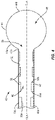
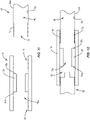
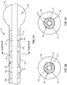
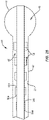
- each of the spaced apart flow controllers 50 have a different height, wherein the flow controller 50 having the greatest height is positioned at proximal portion 42a of cylindrical portion 42 and the flow controller having the least height is positioned at distal portion 42b of cylindrical portion 42, as shown in FIG. 4 . In some embodiments, each of the spaced apart flow controllers 50 have a different height, wherein the flow controller 50 having the greatest height is positioned at distal portion 42b of cylindrical portion 42 and the flow controller 50 having the least height is positioned at proximal portion 42a of cylindrical portion 42, as shown in FIG. 5 .
- the height(s) of the flow controllers 50 between the flow controllers 50 with the greatest and least heights is less than the height of the flow controller 50 with the greatest height and greater than the flow controller 50 with the least height such that flow controllers 50 have a stepped configuration, as shown in FIGS. 4 and 5 .
- a medical practitioner obtains access to a target location including at least one vertebra, such as, for example, a fractured vertebra, in any appropriate manner, such as through incision and retraction of tissue.
- the balloon catheter 40 may be used in any existing surgical method or technique including open surgery, mini-open surgery, minimally invasive surgery including percutaneous surgical implantation, whereby vertebra V is accessed through a micro-incision, or sleeve that provides a protected passageway to the area. Once access to the surgical site(s) is obtained, the particular surgical procedure is performed for treating the bone disorder.
- Balloon catheter 40 is moved through the incision and positioned so that balloon 44 is positioned within a vertebral body of the fractured vertebra. In some embodiments, balloon 44 is moved into the vertebral body when balloon 44 is in the uninflated configuration.
- An inflation material such as, for example, one of the materials discussed above is moved through passageway 46 such that the material flows through passageway 46, out of an opening 56 in distal portion of cylindrical portion 42 and into cavity 48 of balloon 44 to move balloon 44 from the uninflated configuration to the inflated configuration. As the material flows through passageway 46, flow controllers 50 reduce the rate of flow of the material to prevent balloon 44 from being inflated too quickly.
- flow controllers ensure that balloon 44 is gradually inflated such that balloon 44 pushes cancellous bone of the vertebral body towards cortical walls of the vertebral body to form a cavity within the vertebral body.
- the cavity created by balloon 44 is filled with a material, such as, for example, bone cement.
- opening 56 is coaxial with central longitudinal axis CLA.
- balloon catheter 40 comprises one or a plurality of flow controllers 50 coupled to an outer surface 58 of cylindrical portion 42.
- flow controllers 50 may be discrete bands concentric to central longitudinal axis CLA or discrete strips that extend parallel to central longitudinal axis CLA.
- flow controllers 50 are crimped to outer surface 58. At each position along cylindrical portion 42 to which flow controllers 50 are crimped, the diameter of cylindrical portion 42 decreases.
- cylindrical portion 42 comprises a first portion that is free of any flow controllers 50 and has an inner diameter d1 and a second portion that comprises at least one flow controller 50 and has an inner diameter d2 that is less than inner diameter d1.
- cylindrical portion 42 comprises a third portion that comprises at least one additional flow controller 50 and has an inner diameter d3 that is less than inner diameter d2.
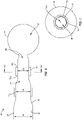
- each of flow controllers 50 extends 360 degrees about central longitudinal axis CLA, as shown in FIG. 7 , for example.
- the changes in the inner diameter of cylindrical portion 42 between inner diameter d1, inner diameter d2 and inner diameter d3 controls the flow of the inflation material through passageway 46 to gradually inflate balloon 44.
- the changes in the inner diameter of cylindrical portion 42 reduce the rate of flow of the material to prevent balloon 40 from being inflated too quickly. That is, the changes in the inner diameter of cylindrical portion 42 ensure that balloon 44 is gradually inflated such that balloon 44 pushes cancellous bone of the vertebral body towards cortical walls of the vertebral body to form a cavity within the vertebral body.
- proximal portion 44a of balloon 44 is coupled to a first section of distal portion 42b of cylindrical portion 42 and distal portion 44b of balloon 44 is coupled to a second section of distal portion 42b.
- Distal portion 42b comprises one or a plurality of apertures 60 that extend through inner and outer surfaces 52, 58 of cylindrical portion 42.
- Cylindrical portion 42 comprises an end wall 62 that defines a distal limit of passageway 46.
- Apertures 60 are in communication with passageway 46 and cavity 48 of balloon 44 such that the inflation material can move out of passageway 46 and into cavity 48 through apertures 60 to inflate balloon 44.
- apertures 60 are nonadjacent to one another or spaced apart radially about a circumference of cylindrical portion 42, as shown in FIG. 9 .
- at least one of apertures 60 may have various cross section configurations, such as, for example, circular, oval, oblong, triangular, rectangular, square, polygonal, irregular, uniform, non-uniform, variable and/or tapered.
- at least one of apertures 60 may be disposed at alternate orientations, relative to central longitudinal axis CLA, such as, for example, transverse, perpendicular and/or other angular orientations such as acute or obtuse, co-axial and/or may be offset or staggered.
- flow controllers 50 are coupled to outer surface 58 of cylindrical portion 42, similar to the embodiment shown in FIG. 6 such that the inner diameter of cylindrical portion 42 changes between inner diameter d1, inner diameter d2 and inner diameter d3 controls the flow of the inflation material through passageway 46 to gradually inflate balloon 44.
- the changes in the inner diameter of cylindrical portion 42 reduce the rate of flow of the material so when the material flows through apertures 60 and into cavity 48 of balloon 44, the inflation material does not to inflate balloon 40 too quickly.
- flow controllers 50 may be discrete bands concentric to central longitudinal axis CLA.
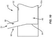
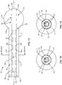
- proximal portion 42a of cylindrical portion 42 of at least one of balloon catheters 40 shown in FIGS. 1 , 6 and 8 comprises an end wall 64 that defines a proximal limit of passageway 46 and a port 66 having a lumen 68 that is in communication with passageway 46, as shown in FIG. 10 .
- the inflation material may be injected into passageway 46 by positioning an inflation material delivery device, such as, for example, a syringe adjacent to port 66 and ejecting the inflation material from the delivery device such that the inflation material moves through an opening 70 of port 66 and lumen 68 of port 66.
- proximal portion 42a of cylindrical portion 42 of at least one of balloon catheters 40 shown in FIGS. 1 , 6 and 8 comprises a threaded portion 72 and an opening 74 that is in communication with passageway 46, as shown in FIG. 11 .
- Balloon catheter 40 further comprises a connector 76 having an inner surface defining a channel 76a having a threaded section 78 and a threaded section 80 that is nonadjacent to or spaced apart from threaded section 78, as shown in FIG. 11 .
- connector 76 comprises one or a plurality of flow controllers 50 within channel 76a.
- flow controllers 50 are positioned between threaded sections 78, 80.
- Threaded portion 72 of cylindrical portion 42 is configured to engage threaded section 78 of connector 76 to couple cylindrical portion 42 to connector 76, as shown in FIG. 12 .
- Threaded section 80 of connector 76 is configured to engage a threaded section of an inflation material delivery device, such as, for example, a syringe 82, as also shown in FIG. 12 .
- an inflation material is ejected from syringe 82 and into channel 76a of connector 76.
- Flow controllers 50 within channel 76 limit the rate of flow of the material through channel 76. The material flows from channel 76a and into passageway 46.
- connector 76 can be variously connected with cylindrical portion 42 and/or syringe 82, such as, for example, monolithic, integral connection, frictional engagement, threaded engagement, mutual grooves, screws, adhesive, nails, barbs and/or raised element.
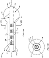
- balloon catheter 40 comprises an inner shaft 84 positioned within cylindrical portion 42, as shown in FIGS. 13-18 , for example.
- a distal portion of inner shaft 84 extends through opening 56 of cylindrical portion 42 such that at least a portion of the distal portion of inner shaft 84 is positioned outside of passageway 46 of cylindrical portion 42.
- Proximal portion 44a of balloon 44 is coupled to distal portion 42b of cylindrical portion 42 and distal portion 44b of balloon 44 is coupled to inner shaft 84.
- inner shaft 84 comprises an inner surface defining a lumen 86 and one or a plurality of apertures 88 that are in communication with lumen 86 and cavity 48 of balloon 44 such that an inflation material can be moved through lumen 86 and apertures 88 and into cavity 48 to inflate balloon 44.
- Inner shaft 84 comprises an end wall 90 that defines a distal limit of lumen 86.
- apertures 88 are spaced apart from one another radially about a circumference of inner shaft 84, similar to apertures 60 shown in FIG. 9 .
- flow controllers 50 are positioned within lumen 86.
- flow controllers 50 are configured to control the flow of the material through lumen 86 as the inflation material travels through lumen 86.
- flow controllers 50 directly engage an inner surface of inner shaft 84 such that a central portion of lumen is unobstructed along central longitudinal axis CLA, as shown in FIGS. 13, 14 and 15 .
- flow controllers 50 directly engage the inner surface of inner shaft 84 such that at least one of flow controllers 50 block and/or obstruct the central portion of lumen 86 along central longitudinal axis CLA, as shown in FIGS. 13A and 13B .
- balloon catheter 40 comprises one or a plurality of flow controllers 50 within lumen 86 that extend continuously from a proximal portion 84a of inner shaft 84 to an opposite distal portion 84b of inner shaft 84. That is, one or more of flow controllers 50 within lumen 86 may have a maximum length along central longitudinal axis CLA that is equal to a maximum length of inner shaft 84 along central longitudinal axis CLA. In some embodiments, balloon catheter 40 comprises a plurality of flow controllers 50 within lumen 86 that each extend continuously from proximal portion 84a to distal portion 84b and are spaced apart from one another about a circumference of inner shaft 84, as shown in FIG. 15 .
- the flow controllers 50 within lumen 86 that extend continuously from proximal portion 84a to distal portion 84b has/have a uniform height from proximal portion 84a to distal portion 84b. In some embodiments, the flow controllers 50 within lumen 86 that extend continuously from proximal portion 84a to distal portion 84b taper from proximal portion 84a to distal portion 84b. In some embodiments, the flow controllers 50 within lumen 86 that extend continuously from proximal portion 84a to distal portion 84b taper from distal portion 84b to proximal portion 84a.
- balloon catheter 40 comprises a plurality of flow controllers 50 within lumen 86 that are spaced apart from one another along central longitudinal axis CLA, as shown in FIG. 13 .
- flow controllers 50 may be discrete bands concentric to central longitudinal axis CLA or discrete strips that extend parallel to central longitudinal axis CLA.
- the spaced apart flow controllers 50 within lumen 86 are uniformly spaced apart from one another along central longitudinal axis CLA.
- at least one of the spaced apart flow controllers 50 within lumen 86 extends 360 degrees about central longitudinal axis CLA, as shown in FIG. 14 , for example.
- flow controllers 50 are discrete bands concentric to central longitudinal axis CLA.
- the spaced apart flow controllers 50 within lumen 86 are spaced apart from one another along central longitudinal axis CLA, as shown in FIG. 13 and are also spaced apart from one another about a circumference of inner shaft 84, as shown in FIG. 15 .
- flow controllers 50 are discrete strips that extend parallel to central longitudinal axis CLA.
- first surfaces 50c of the spaced apart flow controllers 50 within lumen 86 engage the inner surface of inner shaft 84.
- the spaced apart flow controllers 50 within lumen 86 are each tapered from proximal portion 50a to distal portion 50b.
- the spaced apart flow controllers 50 within lumen 86 are each tapered from distal portion 50b to proximal portion 50a.
- each of the spaced apart flow controllers 50 within lumen 86 has the same height, as shown in FIG. 13 .
- each of the spaced apart flow controllers 50 within lumen 86 has a different height, wherein the flow controller 50 having the greatest height is positioned at proximal portion 84a of inner shaft 84 and the flow controller 50 having the least height is positioned at distal portion 84b of inner shaft, as shown in FIG. 16 .
- each of the spaced apart flow controllers 50 within lumen 86 has a different height, wherein the flow controller 50 having the greatest height is positioned at distal portion 84b of inner shaft 84 and the flow controller 50 having the least height is positioned at proximal portion 84a of inner shaft 84, as shown in FIG. 17 .
- the height(s) of the flow controllers 50 within lumen 86 between the flow controllers 50 with the greatest and least heights is less than the height of the flow controller 50 with the greatest height and greater than the flow controller 50 with the least height such that flow controllers 50 have a stepped configuration, as shown in FIGS. 16 and 17 .
- a medical practitioner obtains access to a target location including at least one vertebra, such as, for example, a fractured vertebra, in any appropriate manner, such as through incision and retraction of tissue.
- Balloon catheter 40 is moved through the incision and positioned so that balloon 44 is positioned within a vertebral body of the fractured vertebra. In some embodiments, balloon 44 is moved into the vertebral body when balloon 44 is in the uninflated configuration.
- An inflation material such as, for example, one of the materials discussed above is moved through lumen 86 such that the material flows through lumen 86, out of apertures 88 and into cavity 48 of balloon 44 to move balloon 44 from the uninflated configuration to the inflated configuration.
- flow controllers 50 reduce(s) the rate of flow of the material to prevent balloon 44 from being inflated too quickly. That is, flow controllers 50 ensure that balloon 44 is gradually inflated such that balloon 44 pushes cancellous bone of the vertebral body towards cortical walls of the vertebral body to form a cavity within the vertebral body.
- the cavity created by balloon 44 is filled with a material, such as, for example, bone cement.
- the inflation material fills passageway 46 before or after the inflation material moves balloon 44 from the uninflated configuration to the inflated configuration, as discussed herein. In some embodiments, the inflation material moves out of passageway 46 after the inflation material moves balloon 44 from the uninflated configuration to the inflated configuration to move balloon 44 from the inflated configuration to the uninflated configuration, as discussed herein.
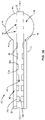
- proximal portion 84a of inner shaft of at least one of balloon catheters 40 shown in FIGS. 13-17 comprises an end wall 92 that defines a proximal limit of lumen 86 and a port 94 having a channel 96 that is in communication with lumen 86, as shown in FIG. 18 .
- Cylindrical portion 42 comprises port 66 that is in communication with passageway 46, as also shown in FIG. 18 and described in greater detail with regard to FIG. 10 .
- the inflation material may be injected into lumen 86 by positioning an inflation material delivery device, such as, for example, a syringe adjacent to port 94 and ejecting the inflation material from the delivery device such that the inflation material moves through an opening 98 of port 94 and lumen 96 of port 94.
- the inflation material will then move through lumen 86 of inner shaft 84 in the direction shown by arrow A in FIG. 18 such that the inflation material moves through at least one flow controller 50 positioned within lumen 86.
- the inflation material will exit lumen 86 via apertures 88 such that the material enters cavity 48 of balloon 44 to move balloon 44 from the uninflated configuration to the inflated configuration.
- at least a portion of passageway 46 is filled with the inflation material when balloon 44 is in the inflated configuration.
- the inflation material moves out of cavity 48 of balloon 44 to move balloon 44 from the inflated configuration to the uninflated configuration. This may be done after balloon 44 creates a cavity in bone, for example. It is envisioned that removing balloon catheter 40 from the patient may be easier and/or cause less damage or damage to the patient when balloon 44 is in the uninflated configuration.
- balloon 44 is moved from the inflated configuration to the uninflated configuration by coupling a suction device, such as, for example, a syringe and/or vacuum source to port 66 such that suction is created to move the inflation material out of cavity 48 of balloon 44 and through passageway 46 of cylindrical portion 42 in direction B shown in FIG. 18 .
- a suction device such as, for example, a syringe and/or vacuum source
- the inflation material will continue to move in arrow B until the material exits passageway 46 through lumen 68 and opening 70 of port 68 of cylindrical portion 42. In some embodiments, the inflation material will remain within cavity 48 of balloon 44 until suction is applied. That is, balloon 44 will remain in the inflated configuration until suction is applied at port 66 to draw the inflation material through passageway 46 of cylindrical portion 42.
- balloon catheter 40 comprises inner shaft 84 and is configured such that the inflation material moves through passageway 46 of cylindrical portion 42 in a space between inner shaft 84 and cylindrical portion 42 to move balloon 44 between the uninflated and inflated configurations, as discussed herein.
- Flow controllers 50 are positioned within passageway 46, between the outer surface of inner shaft 84 and inner surface 52 of cylindrical portion 42, as shown in FIGS. 19-30 , in order to limit the flow rate of the inflation material as it flows through passageway 46.
- balloon catheter 40 comprises one or a plurality of flow controllers 50 that extend continuously from the outer surface of inner shaft 84 to inner surface 52 of cylindrical portion 42. As shown in FIG. 19 , flow controllers 50 are spaced apart from one another along central longitudinal axis CLA.
- balloon catheter 40 may comprise a single flow controller 50 that extends continuously from proximal portion 42a of cylindrical portion 42 to distal portion 42b of cylindrical portion 42 and/or from proximal portion 84a of inner shaft 84 to distal portion 84b of inner shaft 84 such that the single flow controller extends the entire length of at least one of cylindrical portion 42 and inner shaft 84.
- flow controller(s) 50 comprise(s) a plate having one or a plurality of discrete conduits 100 that each extend continuously through and between opposite proximal and distal surfaces 50a, 50b of flow controller(s) 50.
- conduits 100 are nonadjacent to one another or spaced apart such that one conduit 100 is not in communication with another one of conduits 100.
- conduits 100 are positioned radially about a circumference of cylindrical portion 42, as shown in FIG. 20A .
- conduits 100 may have various cross section configurations, such as, for example, oval, oblong, triangular, rectangular, square, polygonal, irregular, uniform, non-uniform, variable, tubular and/or tapered.
- flow controllers comprise a foam material, such as, for example, an open cell foam material or spongiform material/structure comprising a plurality of pores 54, as discussed above with regard to the embodiment shown in FIG. 1B .
- at least one of pores 54 extends through proximal and distal surfaces 50a, 50b a respective flow controller 50.
- at least one of pores 54 extends through one of proximal and distal surfaces 50a, 50b without extending through the other one of proximal and distal surfaces 50a, 50b.
- at least one of pores 54 is in communication with at least another one of pores 54.
- pores 54 are interconnected with one another.
- pores 54 are nonadjacent to one another, spaced apart and/or are not in communication with one another.
- balloon catheter 40 comprises one or a plurality of flow controllers 50 that are coupled to the outer surface of inner shaft 84, as shown in FIG. 21 , for example.
- flow controllers 50 may be discrete bands concentric to central longitudinal axis CLA or discrete strips that extend parallel to central longitudinal axis CLA.
- flow controllers coupled to the outer surface of inner shaft 84 extend continuously from a proximal portion 84a of inner shaft 84 to an opposite distal portion 84b of inner shaft 84. That is, one or more of flow controllers 50 coupled to the outer surface inner shaft 84 may have a maximum length along central longitudinal axis CLA that is equal to a maximum length of inner shaft 84 along central longitudinal axis CLA.
- balloon catheter 40 comprises a single flow controller 50 coupled to the outer surface of inner shaft 84 that extends continuously from proximal portion 84a to distal portion 84b and also extends 360 degrees about central longitudinal axis CLA, as shown in FIG. 22 , for example.
- flow controllers 50 are discrete bands concentric to central longitudinal axis CLA.
- balloon catheter 40 comprises a plurality of flow controllers 50 coupled to the outer surface of inner shaft 84 that extend continuously from proximal portion 84a to distal portion 84b and are spaced apart from one another about a circumference of inner shaft 84, as shown in FIG. 23 .
- balloon catheter 40 comprises a plurality of flow controllers 50 coupled to the outer surface of inner shaft 84 that are spaced apart from one another along central longitudinal axis CLA, as shown in FIG. 21 .
- the spaced apart flow controllers 50 coupled to the outer surface of inner shaft 84 are uniformly spaced apart from one another along central longitudinal axis CLA.
- at least one of the spaced apart flow controllers 50 coupled to the outer surface of inner shaft 84 extends 360 degrees about central longitudinal axis CLA, as shown in FIG. 22 , for example.
- the spaced apart flow controllers 50 coupled to the outer surface of inner shaft 84 are spaced apart from one another along central longitudinal axis CLA, as shown in FIG. 21 and are also spaced apart from one another about a circumference of inner shaft 84, as shown in FIG. 23 .
- the spaced apart flow controllers 50 coupled to the outer surface of inner shaft 84 are each tapered from proximal portion 50a to distal portion 50b. In some embodiments, the spaced apart flow controllers 50 coupled to the outer surface of inner shaft 84 are each tapered from distal portion 50b to proximal portion 50a. In some embodiments, each of the spaced apart flow controllers 50 coupled to the outer surface of inner shaft 84 have the same height, as shown in FIG. 21 .
- each of the spaced apart flow controllers 50 coupled to the outer surface of inner shaft 84 have a different height, wherein the flow controller 50 having the greatest height is positioned at proximal portion 84a of inner shaft 84 and the flow controller 50 having the least height is positioned at distal portion 84b of inner shaft, as shown in FIG. 24 .
- each of the spaced apart flow controllers coupled to the outer surface of inner shaft 84 have a different height, wherein the flow controller 50 having the greatest height is positioned at distal portion 84b of inner shaft 84 and the flow controller 50 having the least height is positioned at proximal portion 84a of inner shaft 84, as shown in FIG. 25 .
- the height(s) of the flow controllers 50 coupled to the outer surface of inner shaft 84 between the flow controllers 50 with the greatest and least heights is less than the height of the flow controller 50 with the greatest height and greater than the flow controller 50 with the least height such that flow controllers 50 have a stepped configuration, as shown in FIGS. 24 and 25 .
- balloon catheter 40 comprises one or a plurality of flow controllers 50 positioned in passageway 46 of cylindrical portion 42 between inner shaft 84 and inner surface 52 of cylindrical portion 42 that are coupled to inner surface 52 of cylindrical portion 42 and extend continuously from a proximal portion 42a of cylindrical portion 42 to an opposite distal portion 42b of cylindrical portion 42. That is, one or more of flow controllers 50 coupled to inner surface 52 of cylindrical portion 42 may have a maximum length along central longitudinal axis CLA that is equal to a maximum length of cylindrical portion 42 along central longitudinal axis CLA.
- balloon catheter 40 comprises a single flow controller 50 coupled to inner surface 52 of cylindrical portion 42 that extends continuously from proximal portion 42a to distal portion 42b and also extends 360 degrees about central longitudinal axis CLA, as shown in FIG. 27 , for example.
- balloon catheter 40 comprises a plurality of flow controllers 50 coupled to inner surface 52 of cylindrical portion 42 that extend continuously from proximal portion 42a to distal portion 42b and are spaced apart from one another about a circumference of cylindrical portion 42, as shown in FIG. 28 .
- the flow controllers 50 coupled to inner surface 52 of cylindrical portion 42 that extend continuously from proximal portion 42a to distal portion 42b have a uniform height from proximal portion 42a to distal portion 42b. In some embodiments, the flow controllers 50 coupled to inner surface 52 of cylindrical portion 42 that extend continuously from proximal portion 42a to distal portion 42b taper from proximal portion 42a to distal portion 42b. In some embodiments, the flow controllers 50 coupled to inner surface 52 of cylindrical portion 42 extend continuously from proximal portion 42a to distal portion 42b taper from distal portion 42b to proximal portion 42a.
- balloon catheter 40 comprises a plurality of flow controllers 50 coupled to inner surface 52 of cylindrical portion 42 that are spaced apart from one another along central longitudinal axis CLA, as shown in FIG. 26 .
- flow controllers 50 may be discrete bands concentric to central longitudinal axis CLA or discrete strips that extend parallel to central longitudinal axis CLA.
- the spaced apart flow controllers 50 coupled to inner surface 52 of cylindrical portion 42 are uniformly spaced apart from one another along central longitudinal axis CLA.
- at least one of the spaced apart flow controllers 50 coupled to inner surface 52 of cylindrical portion 42 extends 360 degrees about central longitudinal axis CLA, as shown in FIG. 27 , for example.
- flow controllers 50 are discrete bands concentric to central longitudinal axis CLA.
- the spaced apart flow controllers 50 coupled to inner surface 52 of cylindrical portion 42 are spaced apart from one another along central longitudinal axis CLA, as shown in FIG. 26 and are also spaced apart from one another about a circumference of inner shaft 84, as shown in FIG. 28 .
- flow controllers 50 are discrete strips that extend parallel to central longitudinal axis CLA.
- the spaced apart flow controllers 50 coupled to inner surface 52 of cylindrical portion 42 are each tapered from proximal portion 50a to distal portion 50b. In some embodiments, the spaced apart flow controllers 50 coupled to inner surface 52 of cylindrical portion 42 are each tapered from distal portion 50b to proximal portion 50a. In some embodiments, each of the spaced apart flow controllers 50 coupled to inner surface 52 of cylindrical portion 42 have the same height, as shown in FIG. 26 .
- each of the spaced apart flow controllers 50 coupled to inner surface 52 of cylindrical portion 42 have a different height, wherein the flow controller 50 having the greatest height is positioned at proximal portion 42a of cylindrical portion 42 and the flow controller 50 having the least height is positioned at distal portion 42b of cylindrical portion 42, as shown in FIG. 29 .
- each of the spaced apart flow controllers 50 inner surface 52 of cylindrical portion 42 have a different height, wherein the flow controller 50 having the greatest height is positioned at distal portion 42b of cylindrical portion 42 and the flow controller 50 having the least height is positioned at proximal portion 42a of cylindrical portion 42, as shown in FIG. 30 .
- the heights of the flow controllers 50 coupled to inner surface 52 of cylindrical portion 42 between the flow controllers 50 with the greatest and least heights is less than the height of the flow controller 50 with the greatest height and greater than the flow controller 50 with the least height such that flow controllers 50 have a stepped configuration, as shown in FIGS. 29 and 30 .
- a medical practitioner obtains access to a target location including at least one vertebra, such as, for example, a fractured vertebra, in any appropriate manner, such as through incision and retraction of tissue.
- Balloon catheter 40 is moved through the incision and positioned so that balloon 44 is positioned within a vertebral body of the fractured vertebra.
- balloon 44 is moved into the vertebral body when balloon 44 is in the uninflated configuration.
- An inflation material such as, for example, one of the materials discussed above is moved through passageway 46 and opening 56 such that the material moves into cavity 48 of balloon 44 to move balloon 44 from the uninflated configuration to the inflated configuration.
- flow controllers 50 reduce the rate of flow of the material to prevent balloon 44 from being inflated too quickly. That is, flow controllers 50 ensure that balloon 44 is gradually inflated such that balloon 44 pushes cancellous bone of the vertebral body towards cortical walls of the vertebral body to form a cavity within the vertebral body.
- the cavity created by balloon 44 is filled with a material, such as, for example, bone cement.
- at least a portion of passageway 46 is filled with the inflation material when balloon 44 is in the inflated configuration.
- balloon catheter 40 comprises inner shaft 84 and one or a plurality of flow controllers 50 coupled to outer surface 58 of cylindrical portion 42.
- flow controllers 50 are discrete bands concentric to central longitudinal axis CLA.
- flow controllers 50 are crimped to outer surface 58. At each position along cylindrical portion 42 to which flow controllers 50 are crimped, the diameter of cylindrical portion 42 decreases.
- cylindrical portion 42 comprises a first portion that is free of any flow controllers 50 and has an inner diameter d1 and a second portion that comprises at least one flow controller 50 and has an inner diameter d2 that is less than inner diameter d1.
- cylindrical portion 42 comprises a third portion that comprises at least one additional flow controller 50 and has an inner diameter d3 that is less than inner diameter d2. In some embodiments, cylindrical portion 42 comprises a fourth portion that comprises at least one additional flow controller 50 and has an inner diameter d4 that is less than inner diameter d3. In some embodiments, each of flow controllers 50 extends 360 degrees about central longitudinal axis CLA, as shown in FIG. 32 , for example.
- the changes in the inner diameter of cylindrical portion 42 between inner diameter d1, inner diameter d2, inner diameter d3 and inner diameter d4 controls the flow of the inflation material through passageway 46 to gradually inflate balloon 44.
- the changes in the inner diameter of cylindrical portion 42 reduce the rate of flow of the material to prevent balloon 40 from being inflated too quickly. That is, the changes in the inner diameter of cylindrical portion 42 ensure that balloon 44 is gradually inflated such that balloon 44 pushes cancellous bone of the vertebral body towards cortical walls of the vertebral body to form a cavity within the vertebral body.
- proximal portion 42a of cylindrical portion 42 of at least one of balloon catheters 40 shown in FIGS. 19-32 comprises end wall 64 that defines a proximal limit of passageway 46 and port 66, as described in greater detail with the discussion of the embodiment shown in FIG. 10 .
- inner shaft 84 extends through end wall 46.
- the inflation material may be injected into passageway 46 by positioning an inflation material delivery device, such as, for example, a syringe adjacent to port 66 and ejecting the inflation material from the delivery device such that the inflation material moves through opening 70 of port 66 and lumen 68 of port 66.
- At least one of balloon catheters 40 shown in FIGS. 19-32 comprises a connector 102 that is positioned about proximal portions 42a, 84a of cylindrical portion 42 and inner shaft 84, as shown in FIG. 34 .
- Connector 102 comprises a port 104 having a lumen 106 that is in communication with passageway 46, as shown in FIG. 34 .
- the inflation material may be injected into passageway 46 by positioning an inflation material delivery device, such as, for example, a syringe adjacent to port 104 and ejecting the inflation material from the delivery device such that the inflation material moves through an opening 108 of port 104 and lumen 106 of port 104.
- balloon catheter 40 comprises at least one or a plurality of flow controllers 50 positioned within passageway 46 adjacent to port 104, as shown in FIG. 34 .
- flow controllers 50 are positioned distal to port 104 such that as an inflation material is ejected from a delivery device and into passageway 46 through port 104, flow controllers 50 will limit the rate of flow of the material through passageway 46.
- at least one of flow controllers 50 adjacent to port 104 extends 360 degrees about central longitudinal axis CLA, as shown in FIG. 35 , for example.
- flow controllers 50 are discrete strips that are concentric with central longitudinal axis CLA.
- flow controllers 50 adjacent to port 104 are spaced apart from one another about a circumference of cylindrical portion 42, as shown in FIG. 36 .
- flow controllers 50 are discrete strips that extend parallel to central longitudinal axis CLA.
Landscapes
- Health & Medical Sciences (AREA)
- Life Sciences & Earth Sciences (AREA)
- Orthopedic Medicine & Surgery (AREA)
- Surgery (AREA)
- Biomedical Technology (AREA)
- Engineering & Computer Science (AREA)
- Nuclear Medicine, Radiotherapy & Molecular Imaging (AREA)
- Heart & Thoracic Surgery (AREA)
- Medical Informatics (AREA)
- Molecular Biology (AREA)
- Animal Behavior & Ethology (AREA)
- General Health & Medical Sciences (AREA)
- Public Health (AREA)
- Veterinary Medicine (AREA)
- Surgical Instruments (AREA)
Description
- The present disclosure generally relates to medical devices for the treatment of bone disorders, and more particularly to devices for treating spina disorders, such as, for example, vertebral compression fractures.
- Height loss is commonly associated with spinal fractures, such as, for example, vertebral compression fractures. Spinal fractures affect a large segment of osteoporotic patients. It is estimated that approximately 700,000 spinal fractures occur annually from osteoporosis, for example. Procedures have been developed to treat spinal fractures. One such procedure is kyphoplasty. Kyphoplasty is a minimally invasive procedure that is used to treat spinal fractures, such as, for example, vertebral compression fractures by inserting one or more balloons, such as, for example, compliant balloons inside a fractured vertebral body. The balloon or balloons are inflated within the fractured vertebral body such that the cancellous bone of the vertebral body is pushed towards cortical walls of the vertebral body to form a cavity within the vertebral body. The cavity is then at least partially filled with a material, such as, for example, bone cement.
- However, conventional spinal fracture treatment procedures lack a means to control the inflation rate of the balloon or balloons. This may lead to uneven inflation, balloon ruptures, or suboptimal balloon performance. To achieve optimal results, there is a need to provide a balloon or balloons that are inflated slowly to allow the balloon or balloons to gradually compress bone and restore height to the vertebral body. Bone is a viscoplastic material that needs time to deform. Fast inflation does not allow the balloon to create a large cavity. Conventional spinal fracture treatment procedures rely on the physician to control the inflation rate of the balloon or balloons. This disclosure describes an improvement over these prior art technologies. Inflating at a lower rate is not typically desired because it leads to a longer procedure time. However, providing a more steady and uniform inflation rate as described herein will lead to better and more predictable patient outcomes.
-
US2014316411A1 discloses systems and methods of using expandable elements inserted into a bone, such as the distal radius, to provide for minimally invasive reduction and fixation of fractures. The disclosed device comprises a shaft, a balloon and a flow controller. - The present invention is defined in claim 1 while preferred embodiments are set forth in the dependent claims.
- New devices are provided for the treatment of bone disorders, and more particularly devices for treating spinal disorders, such as, for example, vertebral compression fractures. In some embodiments, the devices comprise an inflatable bone tamp (IBT) comprising a shaft. A balloon is coupled to the shaft such that a material can flow through the shaft and into the balloon to inflate the balloon. The IBT comprises a shaft extending along a central longitudinal axis between opposite proximal and distal portions;
- a balloon coupled to the distal portion such that a material can flow through the shaft and into the balloon to inflate the balloon; and
- a first flow controller coupled to the shaft that controls the flow of the material through the shaft and into the balloon,
- wherein the first flow controller comprises a plurality of first flow controllers selected from discrete bands concentric to the central longitudinal axis; and discrete strips coupled along the shaft parallel to the central longitudinal axis.
- In some embodiments, the IBT comprises a connector that is coupled to the shaft. In some embodiments, the connector is a V-connector. In some embodiments, the flow controller is coupled to the connector. In some embodiments, the flow controller is mounted in the connector.
- In some embodiments, there is an outer shaft and an inner shaft positioned within the outer shaft. In some embodiments the balloon can be coupled to the inner shaft and/or the outer shaft. In some embodiments, the flow controller is positioned between the outer shaft and the inner shaft. The flow controller can be coupled to the shaft between the proximal portion and the distal portion that controls the flow of the material through the shaft and into the balloon. In some embodiments, the flow controllers are mounted in the space between the inner shaft and the outer shaft. In some embodiments, the flow controller is coupled to the outer shaft. In some embodiments, the flow controller is mounted in the outer shaft. In some embodiments, the flow controller is coupled to the inner shaft. In some embodiments, the flow controller is mounted in the inner shaft. In some embodiments, the flow controller is crimped onto the inner shaft. In some embodiments, the flow controller is crimped onto the outer shaft. In some embodiments, the flow controller is crimped onto the outer shaft and comprises a plurality of flow controllers that act as flow chokes. There are embodiments where the flow controller comprises a spongiform structure.
- Additional features and advantages of various embodiments will be set forth in part in the description that follows, and in part will be apparent from the description, or may be learned by practice of various embodiments. The advantages of various embodiments will be realized and attained by means of the elements and combinations particularly pointed out in the description and appended claims.
- The present disclosure will become more readily apparent from the specific description accompanied by the following drawings, in which:
-
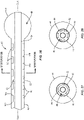
FIG. 1 is a breakaway, side, cross sectional view of a surgical instrument in accordance with the principles of the present disclosure; -
FIG. 1A is a breakaway, side, cross sectional view of one embodiment of the surgical instrument shown inFIG. 1 ; -
FIG. 1B is a cross sectional view of one embodiment of the surgical instrument shown inFIG. 1A ; -
FIG. 2 is a cross sectional view of one embodiment of the surgical instrument shown inFIG. 1 ; -
FIG. 3 is a cross sectional view of one embodiment of the surgical instrument shown inFIG. 1 ; -
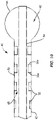
FIG. 4 is a breakaway, side, cross sectional view of one embodiment of the surgical instrument shown inFIG. 1 ; -
FIG. 4 is a breakaway, side, cross sectional view of one embodiment of the surgical instrument shown inFIG. 1 ; -
FIG. 5 is a breakaway, side, cross sectional view of one embodiment of the surgical instrument shown inFIG. 1 ; -
FIG. 6 is a breakaway, side, cross sectional view of a surgical instrument in accordance with the principles of the present disclosure; -
FIG. 7 is a cross sectional view of one embodiment of the surgical instrument shown inFIG. 6 ; -
FIG. 8 is a breakaway, side, cross sectional view of a surgical instrument in accordance with the principles of the present disclosure; -
FIG. 9 is a cross sectional view of one embodiment of the surgical instrument shown inFIG. 8 ; -
FIG. 10 is a breakaway, side, cross sectional view of a portion of one embodiment of the surgical instruments shown inFIGS. 1 ,6 and8 ; -
FIG. 11 is a breakaway, side, cross sectional view of components of one embodiment of the surgical instruments shown inFIGS. 1 ,6 and8 ; -
FIG. 12 is breakaway, a side, cross sectional view of the components shown inFIG. 11 ; -
FIG. 13 is a breakaway, side, cross sectional view of a surgical instrument in accordance with the principles of the present disclosure; -
FIG. 13A is a breakaway, side, cross sectional view of one embodiment of the surgical instrument shown inFIG. 1 ; -
FIG. 13B is a cross sectional view of one embodiment of the surgical instrument shown inFIG. 13A ; -
FIG. 14 is a cross sectional view of one embodiment of the surgical instrument shown inFIG. 13 ; -
FIG. 15 is a cross sectional view of one embodiment of the surgical instrument shown inFIG. 13 ; -
FIG. 16 is a breakaway, side, cross sectional view of one embodiment of the surgical instrument shown inFIG. 15 ; -
FIG. 17 is a breakaway, side, cross sectional view of one embodiment of the surgical instrument shown inFIG. 15 ; -
FIG. 18 is a breakaway, side, cross sectional view of a portion of one embodiment of the surgical instrument shown inFIGS. 13 and13A ; -
FIG. 19 is a breakaway, side, cross sectional view of a surgical instrument in accordance with the principles of the present disclosure; -
FIG. 20A is a cross sectional view of one embodiment of the surgical instrument shown inFIG. 19 ; -
FIG. 20B is a cross sectional view of one embodiment of the surgical instrument shown inFIG. 19 ; -
FIG. 21 is a breakaway, side, cross sectional view of a surgical instrument in accordance with the principles of the present disclosure; -
FIG. 22 is a cross sectional view of one embodiment of the surgical instrument shown inFIG. 21 ; -
FIG. 23 is a cross sectional view of one embodiment of the surgical instrument shown inFIG. 21 ; -
FIG. 24 is a breakaway, side, cross sectional view of one embodiment of the surgical instrument shown inFIG. 23 ; -
FIG. 25 is a breakaway, side, cross sectional view of one embodiment of the surgical instrument shown inFIG. 23 ; -
FIG. 26 is a breakaway, side, cross sectional view of a surgical instrument in accordance with the principles of the present disclosure; -
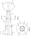
FIG. 27 is a cross sectional view of one embodiment of the surgical instrument shown inFIG. 26 ; -
FIG. 28 is a cross sectional view of one embodiment of the surgical instrument shown inFIG. 26 ; -
FIG. 29 is a breakaway, side, cross sectional view of one embodiment of the surgical instrument shown inFIG. 26 ; -
FIG. 30 is a breakaway, side, cross sectional view of one embodiment of the surgical instrument shown inFIG. 26 ; -
FIG. 31 is a breakaway, side, cross sectional view of a surgical instrument in accordance with the principles of the present disclosure; -
FIG. 32 is a cross sectional view of one embodiment of the surgical instrument shown inFIG. 31 ; -
FIG. 33 is a breakaway, side, cross sectional view of a portion of one embodiment of the surgical instruments shown inFIGS. 19 ,21 ,26 and31 ; -
FIG. 34 is a breakaway, side, cross sectional view of a portion of one embodiment of the surgical instruments shown inFIGS. 19 ,21 ,26 and31 ; -
FIG. 35 is a cross sectional view of one embodiment of the portion of one embodiment of components of the surgical instruments shown inFIGS. 19 ,21 ,26 and31 ; and -
FIG. 36 is a cross sectional view of one embodiment of the portion of one embodiment of components of the surgical instruments shown inFIGS. 19 ,21 ,26 and31 . - Reference will now be made in detail to certain embodiments of the invention, examples of which are illustrated in the accompanying drawings. While the invention will be described in conjunction with the illustrated embodiments, it will be understood that they are not intended to limit the invention to those embodiments.
- This disclosure is directed to an inflatable bone tamp, such as, for example, a
balloon catheter 40. In some embodiments, the components ofballoon catheter 40 can be fabricated from biologically acceptable materials suitable for medical applications, including metals, synthetic polymers, ceramics and bone material and/or their composites, depending on the particular application and/or preference of a medical practitioner. For example, the components of balloon catheter 40, individually or collectively, can be fabricated from materials such as stainless steel alloys, commercially pure titanium, titanium alloys, Grade 5 titanium, super-elastic titanium alloys, cobalt-chrome alloys, stainless steel alloys, superelastic metallic alloys (e.g., Nitinol, super elasto-plastic metals, such as GUM METAL® manufactured by Toyota Material Incorporated of Japan), ceramics and composites thereof such as calcium phosphate (e.g., SKELITE™ manufactured by Biologix Inc.), thermoplastics such as polyaryletherketone (PAEK) including polyetheretherketone (PEEK), polyetherketoneketone (PEKK) and polyetherketone (PEK), carbon-PEEK composites, PEEK-BaSO4 polymeric rubbers, polyethylene terephthalate (PET), fabric, silicone, polyurethane, silicone-polyurethane copolymers, polymeric rubbers, polyolefin rubbers, hydrogels, semi-rigid and rigid materials, elastomers, rubbers, thermoplastic elastomers, thermoset elastomers, elastomeric composites, rigid polymers including polyphenylene, polyamide, polyimide, polyetherimide, polyethylene, epoxy, bone material including autograft, allograft, xenograft or transgenic cortical and/or corticocancellous bone, and tissue growth or differentiation factors, partially resorbable materials, such as, for example, composites of metals and calcium-based ceramics, composites of PEEK and calcium based ceramics, composites of PEEK with resorbable polymers, totally resorbable materials, such as, for example, calcium based ceramics such as calcium phosphate, tri-calcium phosphate (TCP), hydroxyapatite (HA)-TCP, calcium sulfate, or other resorbable polymers such as polyaetide, polyglycolide, polytyrosine carbonate, polycaroplaetohe and their combinations. - Various components of
balloon catheter 40 may have material composites, including the above materials, to achieve various desired characteristics such as strength, rigidity, elasticity, compliance, biomechanical performance, durability and radiolucency or imaging preference. The components ofballoon catheter 40, individually or collectively, may also be fabricated from a heterogeneous material such as a combination of two or more of the above-described materials. The components ofballoon catheter 40 may be monolithically formed, integrally connected or comprise fastening elements and/or instruments, as described herein. -
Balloon catheter 40 comprises an outer shaft orcylindrical portion 42 and aballoon 44 coupled tocylindrical portion 42. In the embodiments shown inFIGS. 1-5 , aproximal portion 44a ofballoon 44 is coupled tocylindrical portion 42 and an oppositedistal portion 44b ofballoon 44 is spaced apart from or nonadjacent to thecylindrical portion 42.Cylindrical portion 42 is hollow and defines apassageway 46. In some embodiments,passageway 46 is in communication with aninternal chamber 48 ofballoon 44. In some embodiments,passageway 46 is configured to form passage of a material to moveballoon 44 from an unexpanded configuration, such as, for example, an uninflated configuration to an expanded configuration, such as, for example, an inflated configuration. That is, a material may be moved throughpassageway 46 and intochamber 48 to moveballoon 44 from the uninflated configuration to the inflated configuration. Whenballoon 44 is in the inflated configuration,balloon 44 has a maximum diameter that is greater than the maximum diameter ofballoon 44 whenballoon 44 is in the uninflated configuration. In some embodiments, the material is a liquid, such as, for example, a contrast solution, saline or water. In some embodiments,passageway 46 is configured for passage of a material to moveballoon 44 from the inflated configuration to the uninflated configuration, as discussed herein. That is, the material moves throughpassageway 46 to allowballoon 44 to deflate. - In some embodiments,
cylindrical portion 42 is a hollow shaft or tube. In some embodiments,cylindrical portion 42 is flexible to allowcylindrical portion 42 to bend ascylindrical portion 42 is navigated through a patient's anatomy. For example,cylindrical portion 42 may be flexible to allowcylindrical portion 42 to be navigated along a curved path created by a medical practitioner in order to positionballoon 44 at, in or near a target location or treatment zone, such as, for example, within a vertebral body. In embodiments whereincylindrical portion 42 is flexible,cylindrical portion 42 can be bent without breakingcylindrical portion 42. In some embodiments,cylindrical portion 42 is rigid such thatcylindrical portion 42 cannot be bent withoutcylindrical portion 42 breaking. For example,cylindrical portion 42 may be rigid to provide strength tocylindrical portion 42 in applications whereinballoon catheter 40 is navigated along a straight path created by a medical practitioner in order to positionballoon 44 at, in or near a target location or treatment zone, such as, for example, a space within a vertebral body. - In some embodiments,
balloon 44 is made from a resilient biocompatible material. In one embodiment,balloon 44 is a compliant balloon that resists stretching. In one embodiment,balloon 44 comprises polyolefin copolymer (POC), Polyurethane, Nylon. In one embodiment,balloon 44 is a non-compliant or semi-compliant balloon that stretches, at least to some degree. In one embodiment,balloon 44 comprises polyethylene terapthelate (PET). In some embodiments,balloon 44 can have various cross section configurations whenballoon 44 is in the inflated configuration, such as, for example, oval, oblong, triangular, rectangular, square, polygonal, irregular, uniform, non-uniform, variable, tubular and/or tapered. In some embodiments, an outer surface ofballoon 44 may have various surface configurations, such as, for example, smooth and/or surface configurations to enhance fixation with tissue, such as, for example, rough, arcuate, undulating, porous, semi-porous, dimpled, polished and/or textured. -
Balloon 44 can be a single or a multi-layered balloon, where each balloon layer has the same diameter and/or wall thickness, is comprised of the same material or materials having substantially identical mechanical properties, and has the same degree of molecular orientation in the body portion of the balloon. It will be apparent that in some situations it will be desirable to have some balloon layers having different thicknesses, materials, and/or degree of molecular orientations upon deflation, while at the same time having equivalent size, mechanical properties, and/or orientation upon inflation. -
Balloon catheter 40 comprises a plurality offlow controllers 50. In the embodiments shown inFIGS. 1-5 , flowcontrollers 50 are positioned withincylindrical portion 42. In these embodiments,flow controllers 50 are configured to control the flow of the material throughpassageway 46 as the material travels throughpassageway 46. In some embodiments,flow controllers 50 directly engage aninner surface 52 ofcylindrical portion 42 such that a central portion ofpassageway 46 is unobstructed along a central longitudinal axis CLA defined bycylindrical portion 42, as shown inFIGS. 1, 2 and 3 . In some embodiments,flow controllers 50 directly engageinner surface 52 ofcylindrical portion 42 such that at least one offlow controllers 50 block and/or obstruct the central portion ofpassageway 46 along central longitudinal axis CLA, as shown inFIGS. 1A and 1B . - In some embodiments,
flow controllers 50 comprise a material, such as, for example, one of the materials discussed herein. In some embodiments,flow controllers 50 comprise a non-porous material.Flow controller 50 is comprised of discrete bands concentric to central longitudinal axis CLA or discrete strips that extend parallel to central longitudinal axis CLA, as shown inFIGS. 1-3 . In some embodiments,flow controllers 50 comprise a porous material that may be a lattice-like or spongiform structure. In some embodiments,flow controllers 50 comprise a foam material, such as, for example, an open cell foam material or spongiform material/structure. In some embodiments, the open cell foam material or spongiform material/structure comprises one or a plurality ofpores 54, as shown inFIG. 1B . In some embodiments, at least one ofpores 54 extends through opposite proximal anddistal surfaces respective flow controller 50. In some embodiments, at least one ofpores 54 extends through one of proximal anddistal surfaces distal surfaces pores 54 is in communication with at least another one of pores 54. In some embodiments, pores 54 are interconnected with one another. In some embodiments, pores 54 are nonadjacent to one another and/or are not in communication with one another. - In some embodiments,
balloon catheter 40 comprises a plurality offlow controllers 50 that extend continuously from aproximal portion 42a ofcylindrical portion 42 to an oppositedistal portion 42b ofcylindrical portion 42. That is,flow controllers 50 may have a maximum length along central longitudinal axis CLA that is equal to a maximum length ofcylindrical portion 42 along central longitudinal axis CLA. In some embodiments,balloon catheter 40 comprises asingle flow controller 50 that that extends continuously fromproximal portion 42a todistal portion 42b and also extends 360 degrees about central longitudinal axis CLA, as shown inFIG. 2 , for example. In some embodiments,balloon catheter 40 comprises a plurality offlow controllers 50 that extends continuously fromproximal portion 42a todistal portion 42b and are nonadjacent to one another or spaced apart about a circumference ofcylindrical portion 42, as shown inFIG. 3 .Flow Controllers 50 can be comprised of discrete strips coupled along the shaft parallel to the central longitudinal axis.Flow controllers 50 each can have a height defined between opposite first andsecond surfaces FIG. 1 . In some embodiments, the flow controller can be discrete strips coupled along the shaft that extend continuously fromproximal portion 42a todistal portion 42b with a uniform height fromproximal portion 42a todistal portion 42b. In some embodiments, theflow controller 50 can be discrete strips that extend continuously fromproximal portion 42a todistal portion 42b taper fromproximal portion 42a todistal portion 42b. In some embodiments, theflow controllers 50 that extend continuously fromproximal portion 42a todistal portion 42b taper fromdistal portion 42b toproximal portion 42a. - In some embodiments,
balloon catheter 40 comprises a plurality offlow controllers 50 that are nonadjacent to one another or spaced apart along central longitudinal axis CLA, as shown inFIG. 1 . In some embodiments,flow controllers 50 are discrete bands concentric to central longitudinal axis CLA. In some embodiments, the spaced apart flowcontrollers 50 are uniformly nonadjacent to one another or spaced apart along central longitudinal axis CLA. In some embodiments, at least one of the spaced apart flowcontrollers 50 extends 360 degrees about central longitudinal axis CLA, as shown inFIG. 2 , for example. In such embodiments,flow controllers 50 are discrete bands concentric to central longitudinal axis CLA. In some embodiments, the spaced apart flowcontrollers 50 are nonadjacent to one another or spaced apart along central longitudinal axis CLA, as shown inFIG. 1 and are also nonadjacent to one another or spaced apart about a circumference ofcylindrical portion 42, as shown inFIG. 3 . In such embodiments,flow controllers 50 are discrete strips that extend parallel to central longitudinal axis CLA. - In the embodiments shown in
FIGS. 1-5 ,first surfaces 50c of the spaced apart flowcontrollers 50 engageinner surface 52 ofcylindrical portion 42. In some embodiments, the spaced apart ordiscrete flow controllers 50 are each tapered fromproximal portion 50a todistal portion 50b. In some embodiments, thediscrete flow controllers 50 are each tapered fromdistal portion 50b toproximal portion 50a. In some embodiments, each of thediscrete flow controllers 50 have the same height, as shown inFIG. 1 . In some embodiments, each of the spaced apart flowcontrollers 50 have a different height, wherein theflow controller 50 having the greatest height is positioned atproximal portion 42a ofcylindrical portion 42 and the flow controller having the least height is positioned atdistal portion 42b ofcylindrical portion 42, as shown inFIG. 4 . In some embodiments, each of the spaced apart flowcontrollers 50 have a different height, wherein theflow controller 50 having the greatest height is positioned atdistal portion 42b ofcylindrical portion 42 and theflow controller 50 having the least height is positioned atproximal portion 42a ofcylindrical portion 42, as shown inFIG. 5 . The height(s) of theflow controllers 50 between theflow controllers 50 with the greatest and least heights is less than the height of theflow controller 50 with the greatest height and greater than theflow controller 50 with the least height such thatflow controllers 50 have a stepped configuration, as shown inFIGS. 4 and5 . - In anon claimed use, to treat a bone disorder, such as, for example, a spinal fracture, a medical practitioner obtains access to a target location including at least one vertebra, such as, for example, a fractured vertebra, in any appropriate manner, such as through incision and retraction of tissue. It is envisioned that the
balloon catheter 40 may be used in any existing surgical method or technique including open surgery, mini-open surgery, minimally invasive surgery including percutaneous surgical implantation, whereby vertebra V is accessed through a micro-incision, or sleeve that provides a protected passageway to the area. Once access to the surgical site(s) is obtained, the particular surgical procedure is performed for treating the bone disorder. -
Balloon catheter 40 is moved through the incision and positioned so thatballoon 44 is positioned within a vertebral body of the fractured vertebra. In some embodiments,balloon 44 is moved into the vertebral body whenballoon 44 is in the uninflated configuration. An inflation material, such as, for example, one of the materials discussed above is moved throughpassageway 46 such that the material flows throughpassageway 46, out of anopening 56 in distal portion ofcylindrical portion 42 and intocavity 48 ofballoon 44 to moveballoon 44 from the uninflated configuration to the inflated configuration. As the material flows throughpassageway 46,flow controllers 50 reduce the rate of flow of the material to preventballoon 44 from being inflated too quickly. That is, flow controllers ensure thatballoon 44 is gradually inflated such thatballoon 44 pushes cancellous bone of the vertebral body towards cortical walls of the vertebral body to form a cavity within the vertebral body. In some embodiments, the cavity created byballoon 44 is filled with a material, such as, for example, bone cement. In some embodiments, opening 56 is coaxial with central longitudinal axis CLA. - In one embodiment, shown in
FIG. 6 ,balloon catheter 40 comprises one or a plurality offlow controllers 50 coupled to anouter surface 58 ofcylindrical portion 42. In such embodiments,flow controllers 50 may be discrete bands concentric to central longitudinal axis CLA or discrete strips that extend parallel to central longitudinal axis CLA.. In some embodiments,flow controllers 50 are crimped toouter surface 58. At each position alongcylindrical portion 42 to whichflow controllers 50 are crimped, the diameter ofcylindrical portion 42 decreases. For example,cylindrical portion 42 comprises a first portion that is free of anyflow controllers 50 and has an inner diameter d1 and a second portion that comprises at least oneflow controller 50 and has an inner diameter d2 that is less than inner diameter d1. In some embodiments,cylindrical portion 42 comprises a third portion that comprises at least oneadditional flow controller 50 and has an inner diameter d3 that is less than inner diameter d2. In some embodiments, each offlow controllers 50 extends 360 degrees about central longitudinal axis CLA, as shown inFIG. 7 , for example. - The changes in the inner diameter of
cylindrical portion 42 between inner diameter d1, inner diameter d2 and inner diameter d3 controls the flow of the inflation material throughpassageway 46 to gradually inflateballoon 44. In particular, as the inflation material flows throughpassageway 46, the changes in the inner diameter ofcylindrical portion 42 reduce the rate of flow of the material to preventballoon 40 from being inflated too quickly. That is, the changes in the inner diameter ofcylindrical portion 42 ensure thatballoon 44 is gradually inflated such thatballoon 44 pushes cancellous bone of the vertebral body towards cortical walls of the vertebral body to form a cavity within the vertebral body. - In one embodiment, shown in
FIG. 8 ,proximal portion 44a ofballoon 44 is coupled to a first section ofdistal portion 42b ofcylindrical portion 42 anddistal portion 44b ofballoon 44 is coupled to a second section ofdistal portion 42b.Distal portion 42b comprises one or a plurality ofapertures 60 that extend through inner andouter surfaces cylindrical portion 42.Cylindrical portion 42 comprises anend wall 62 that defines a distal limit ofpassageway 46.Apertures 60 are in communication withpassageway 46 andcavity 48 ofballoon 44 such that the inflation material can move out ofpassageway 46 and intocavity 48 throughapertures 60 to inflateballoon 44. In some embodiments,apertures 60 are nonadjacent to one another or spaced apart radially about a circumference ofcylindrical portion 42, as shown inFIG. 9 . In some embodiments, at least one ofapertures 60 may have various cross section configurations, such as, for example, circular, oval, oblong, triangular, rectangular, square, polygonal, irregular, uniform, non-uniform, variable and/or tapered. In some embodiments, at least one ofapertures 60 may be disposed at alternate orientations, relative to central longitudinal axis CLA, such as, for example, transverse, perpendicular and/or other angular orientations such as acute or obtuse, co-axial and/or may be offset or staggered. - As shown in
FIG. 8 , flowcontrollers 50 are coupled toouter surface 58 ofcylindrical portion 42, similar to the embodiment shown inFIG. 6 such that the inner diameter ofcylindrical portion 42 changes between inner diameter d1, inner diameter d2 and inner diameter d3 controls the flow of the inflation material throughpassageway 46 to gradually inflateballoon 44. In particular, as the inflation material flows throughpassageway 46, the changes in the inner diameter ofcylindrical portion 42 reduce the rate of flow of the material so when the material flows throughapertures 60 and intocavity 48 ofballoon 44, the inflation material does not to inflateballoon 40 too quickly. That is, the changes in the inner diameter ofcylindrical portion 42 ensure thatballoon 44 is gradually inflated such thatballoon 44 pushes cancellous bone of the vertebral body towards cortical walls of the vertebral body to form a cavity within the vertebral body. In such embodiments,flow controllers 50 may be discrete bands concentric to central longitudinal axis CLA. - In some embodiments,
proximal portion 42a ofcylindrical portion 42 of at least one ofballoon catheters 40 shown inFIGS. 1 ,6 and8 comprises anend wall 64 that defines a proximal limit ofpassageway 46 and aport 66 having alumen 68 that is in communication withpassageway 46, as shown inFIG. 10 . The inflation material may be injected intopassageway 46 by positioning an inflation material delivery device, such as, for example, a syringe adjacent to port 66 and ejecting the inflation material from the delivery device such that the inflation material moves through anopening 70 ofport 66 andlumen 68 ofport 66. - In some embodiments,
proximal portion 42a ofcylindrical portion 42 of at least one ofballoon catheters 40 shown inFIGS. 1 ,6 and8 comprises a threadedportion 72 and anopening 74 that is in communication withpassageway 46, as shown inFIG. 11 .Balloon catheter 40 further comprises aconnector 76 having an inner surface defining achannel 76a having a threadedsection 78 and a threadedsection 80 that is nonadjacent to or spaced apart from threadedsection 78, as shown inFIG. 11 . In some embodiments,connector 76 comprises one or a plurality offlow controllers 50 withinchannel 76a. In some embodiments,flow controllers 50 are positioned between threadedsections portion 72 ofcylindrical portion 42 is configured to engage threadedsection 78 ofconnector 76 to couplecylindrical portion 42 toconnector 76, as shown inFIG. 12 . Threadedsection 80 ofconnector 76 is configured to engage a threaded section of an inflation material delivery device, such as, for example, a syringe 82, as also shown inFIG. 12 . In some embodiment, an inflation material is ejected from syringe 82 and intochannel 76a ofconnector 76.Flow controllers 50 withinchannel 76 limit the rate of flow of the material throughchannel 76. The material flows fromchannel 76a and intopassageway 46. In some embodiments,connector 76 can be variously connected withcylindrical portion 42 and/or syringe 82, such as, for example, monolithic, integral connection, frictional engagement, threaded engagement, mutual grooves, screws, adhesive, nails, barbs and/or raised element. - In some embodiments,
balloon catheter 40 comprises aninner shaft 84 positioned withincylindrical portion 42, as shown inFIGS. 13-18 , for example. A distal portion ofinner shaft 84 extends through opening 56 ofcylindrical portion 42 such that at least a portion of the distal portion ofinner shaft 84 is positioned outside ofpassageway 46 ofcylindrical portion 42.Proximal portion 44a ofballoon 44 is coupled todistal portion 42b ofcylindrical portion 42 anddistal portion 44b ofballoon 44 is coupled toinner shaft 84. In some embodiments,inner shaft 84 comprises an inner surface defining alumen 86 and one or a plurality ofapertures 88 that are in communication withlumen 86 andcavity 48 ofballoon 44 such that an inflation material can be moved throughlumen 86 andapertures 88 and intocavity 48 to inflateballoon 44.Inner shaft 84 comprises anend wall 90 that defines a distal limit oflumen 86. In some embodiments,apertures 88 are spaced apart from one another radially about a circumference ofinner shaft 84, similar toapertures 60 shown inFIG. 9 . - One or a plurality of
flow controllers 50 are positioned withinlumen 86. In the embodiments shown inFIGS. 13-18 ,flow controllers 50 are configured to control the flow of the material throughlumen 86 as the inflation material travels throughlumen 86. In some embodiments,flow controllers 50 directly engage an inner surface ofinner shaft 84 such that a central portion of lumen is unobstructed along central longitudinal axis CLA, as shown inFIGS. 13, 14 and 15 . In some embodiments,flow controllers 50 directly engage the inner surface ofinner shaft 84 such that at least one offlow controllers 50 block and/or obstruct the central portion oflumen 86 along central longitudinal axis CLA, as shown inFIGS. 13A and 13B . - In some embodiments,
balloon catheter 40 comprises one or a plurality offlow controllers 50 withinlumen 86 that extend continuously from aproximal portion 84a ofinner shaft 84 to an oppositedistal portion 84b ofinner shaft 84. That is, one or more offlow controllers 50 withinlumen 86 may have a maximum length along central longitudinal axis CLA that is equal to a maximum length ofinner shaft 84 along central longitudinal axis CLA. In some embodiments,balloon catheter 40 comprises a plurality offlow controllers 50 withinlumen 86 that each extend continuously fromproximal portion 84a todistal portion 84b and are spaced apart from one another about a circumference ofinner shaft 84, as shown inFIG. 15 . In some embodiments, theflow controllers 50 withinlumen 86 that extend continuously fromproximal portion 84a todistal portion 84b has/have a uniform height fromproximal portion 84a todistal portion 84b. In some embodiments, theflow controllers 50 withinlumen 86 that extend continuously fromproximal portion 84a todistal portion 84b taper fromproximal portion 84a todistal portion 84b. In some embodiments, theflow controllers 50 withinlumen 86 that extend continuously fromproximal portion 84a todistal portion 84b taper fromdistal portion 84b toproximal portion 84a. - In some embodiments,
balloon catheter 40 comprises a plurality offlow controllers 50 withinlumen 86 that are spaced apart from one another along central longitudinal axis CLA, as shown inFIG. 13 . In such embodiments,flow controllers 50 may be discrete bands concentric to central longitudinal axis CLA or discrete strips that extend parallel to central longitudinal axis CLA. In some embodiments, the spaced apart flowcontrollers 50 withinlumen 86 are uniformly spaced apart from one another along central longitudinal axis CLA. In some embodiments, at least one of the spaced apart flowcontrollers 50 withinlumen 86 extends 360 degrees about central longitudinal axis CLA, as shown inFIG. 14 , for example. In such embodiments,flow controllers 50 are discrete bands concentric to central longitudinal axis CLA. In some embodiments, the spaced apart flowcontrollers 50 withinlumen 86 are spaced apart from one another along central longitudinal axis CLA, as shown inFIG. 13 and are also spaced apart from one another about a circumference ofinner shaft 84, as shown inFIG. 15 . In such embodiments,flow controllers 50 are discrete strips that extend parallel to central longitudinal axis CLA. - In the embodiments shown in
FIGS. 13-17 ,first surfaces 50c of the spaced apart flowcontrollers 50 withinlumen 86 engage the inner surface ofinner shaft 84. In some embodiments, the spaced apart flowcontrollers 50 withinlumen 86 are each tapered fromproximal portion 50a todistal portion 50b. In some embodiments, the spaced apart flowcontrollers 50 withinlumen 86 are each tapered fromdistal portion 50b toproximal portion 50a. In some embodiments, each of the spaced apart flowcontrollers 50 withinlumen 86 has the same height, as shown inFIG. 13 . In some embodiments, each of the spaced apart flowcontrollers 50 withinlumen 86 has a different height, wherein theflow controller 50 having the greatest height is positioned atproximal portion 84a ofinner shaft 84 and theflow controller 50 having the least height is positioned atdistal portion 84b of inner shaft, as shown inFIG. 16 . In some embodiments, each of the spaced apart flowcontrollers 50 withinlumen 86 has a different height, wherein theflow controller 50 having the greatest height is positioned atdistal portion 84b ofinner shaft 84 and theflow controller 50 having the least height is positioned atproximal portion 84a ofinner shaft 84, as shown inFIG. 17 . The height(s) of theflow controllers 50 withinlumen 86 between theflow controllers 50 with the greatest and least heights is less than the height of theflow controller 50 with the greatest height and greater than theflow controller 50 with the least height such thatflow controllers 50 have a stepped configuration, as shown inFIGS. 16 and17 . - In anon claimed use, to treat a bone disorder, such as, for example, a spinal fracture, a medical practitioner obtains access to a target location including at least one vertebra, such as, for example, a fractured vertebra, in any appropriate manner, such as through incision and retraction of tissue.
Balloon catheter 40 is moved through the incision and positioned so thatballoon 44 is positioned within a vertebral body of the fractured vertebra. In some embodiments,balloon 44 is moved into the vertebral body whenballoon 44 is in the uninflated configuration. An inflation material, such as, for example, one of the materials discussed above is moved throughlumen 86 such that the material flows throughlumen 86, out ofapertures 88 and intocavity 48 ofballoon 44 to moveballoon 44 from the uninflated configuration to the inflated configuration. As the material flows throughlumen 86,flow controllers 50 reduce(s) the rate of flow of the material to preventballoon 44 from being inflated too quickly. That is,flow controllers 50 ensure thatballoon 44 is gradually inflated such thatballoon 44 pushes cancellous bone of the vertebral body towards cortical walls of the vertebral body to form a cavity within the vertebral body. In some embodiments, the cavity created byballoon 44 is filled with a material, such as, for example, bone cement. In some embodiments, the inflation material fillspassageway 46 before or after the inflation material movesballoon 44 from the uninflated configuration to the inflated configuration, as discussed herein. In some embodiments, the inflation material moves out ofpassageway 46 after the inflation material movesballoon 44 from the uninflated configuration to the inflated configuration to moveballoon 44 from the inflated configuration to the uninflated configuration, as discussed herein. - In some embodiments,
proximal portion 84a of inner shaft of at least one ofballoon catheters 40 shown inFIGS. 13-17 comprises anend wall 92 that defines a proximal limit oflumen 86 and aport 94 having achannel 96 that is in communication withlumen 86, as shown inFIG. 18 .Cylindrical portion 42 comprisesport 66 that is in communication withpassageway 46, as also shown inFIG. 18 and described in greater detail with regard toFIG. 10 . In some embodiments, the inflation material may be injected intolumen 86 by positioning an inflation material delivery device, such as, for example, a syringe adjacent to port 94 and ejecting the inflation material from the delivery device such that the inflation material moves through anopening 98 ofport 94 andlumen 96 ofport 94. The inflation material will then move throughlumen 86 ofinner shaft 84 in the direction shown by arrow A inFIG. 18 such that the inflation material moves through at least oneflow controller 50 positioned withinlumen 86. The inflation material will exitlumen 86 viaapertures 88 such that the material enterscavity 48 ofballoon 44 to moveballoon 44 from the uninflated configuration to the inflated configuration. In some embodiments, at least a portion ofpassageway 46 is filled with the inflation material whenballoon 44 is in the inflated configuration. - In some non claimed embodiments, the inflation material moves out of
cavity 48 ofballoon 44 to moveballoon 44 from the inflated configuration to the uninflated configuration. This may be done afterballoon 44 creates a cavity in bone, for example. It is envisioned that removingballoon catheter 40 from the patient may be easier and/or cause less damage or damage to the patient whenballoon 44 is in the uninflated configuration. In some embodiments,balloon 44 is moved from the inflated configuration to the uninflated configuration by coupling a suction device, such as, for example, a syringe and/or vacuum source to port 66 such that suction is created to move the inflation material out ofcavity 48 ofballoon 44 and throughpassageway 46 ofcylindrical portion 42 in direction B shown inFIG. 18 . The inflation material will continue to move in arrow B until the material exitspassageway 46 throughlumen 68 andopening 70 ofport 68 ofcylindrical portion 42. In some embodiments, the inflation material will remain withincavity 48 ofballoon 44 until suction is applied. That is,balloon 44 will remain in the inflated configuration until suction is applied atport 66 to draw the inflation material throughpassageway 46 ofcylindrical portion 42. - In some embodiments,
balloon catheter 40 comprisesinner shaft 84 and is configured such that the inflation material moves throughpassageway 46 ofcylindrical portion 42 in a space betweeninner shaft 84 andcylindrical portion 42 to moveballoon 44 between the uninflated and inflated configurations, as discussed herein.Flow controllers 50 are positioned withinpassageway 46, between the outer surface ofinner shaft 84 andinner surface 52 ofcylindrical portion 42, as shown inFIGS. 19-30 , in order to limit the flow rate of the inflation material as it flows throughpassageway 46. - In one embodiment, shown in
FIGS. 19-20B ,balloon catheter 40 comprises one or a plurality offlow controllers 50 that extend continuously from the outer surface ofinner shaft 84 toinner surface 52 ofcylindrical portion 42. As shown inFIG. 19 ,flow controllers 50 are spaced apart from one another along central longitudinal axis CLA. In a non claimed embodiment,balloon catheter 40 may comprise asingle flow controller 50 that extends continuously fromproximal portion 42a ofcylindrical portion 42 todistal portion 42b ofcylindrical portion 42 and/or fromproximal portion 84a ofinner shaft 84 todistal portion 84b ofinner shaft 84 such that the single flow controller extends the entire length of at least one ofcylindrical portion 42 andinner shaft 84. - In the non claimed embodiment shown in
FIG. 20A , flow controller(s) 50 comprise(s) a plate having one or a plurality ofdiscrete conduits 100 that each extend continuously through and between opposite proximal anddistal surfaces conduits 100,conduits 100 are nonadjacent to one another or spaced apart such that oneconduit 100 is not in communication with another one ofconduits 100. In some embodiments,conduits 100 are positioned radially about a circumference ofcylindrical portion 42, as shown inFIG. 20A . In some embodiments,conduits 100 may have various cross section configurations, such as, for example, oval, oblong, triangular, rectangular, square, polygonal, irregular, uniform, non-uniform, variable, tubular and/or tapered. - In the embodiment shown in
FIG. 20B , flow controllers comprise a foam material, such as, for example, an open cell foam material or spongiform material/structure comprising a plurality ofpores 54, as discussed above with regard to the embodiment shown inFIG. 1B . In some embodiments, at least one ofpores 54 extends through proximal anddistal surfaces respective flow controller 50. In some embodiments, at least one ofpores 54 extends through one of proximal anddistal surfaces distal surfaces pores 54 is in communication with at least another one of pores 54. In some embodiments, pores 54 are interconnected with one another. In some embodiments, pores 54 are nonadjacent to one another, spaced apart and/or are not in communication with one another. - In some embodiments,
balloon catheter 40 comprises one or a plurality offlow controllers 50 that are coupled to the outer surface ofinner shaft 84, as shown inFIG. 21 , for example. In such embodiments,flow controllers 50 may be discrete bands concentric to central longitudinal axis CLA or discrete strips that extend parallel to central longitudinal axis CLA. In some embodiments, flow controllers coupled to the outer surface ofinner shaft 84 extend continuously from aproximal portion 84a ofinner shaft 84 to an oppositedistal portion 84b ofinner shaft 84. That is, one or more offlow controllers 50 coupled to the outer surfaceinner shaft 84 may have a maximum length along central longitudinal axis CLA that is equal to a maximum length ofinner shaft 84 along central longitudinal axis CLA. In a non claimed embodiment,balloon catheter 40 comprises asingle flow controller 50 coupled to the outer surface ofinner shaft 84 that extends continuously fromproximal portion 84a todistal portion 84b and also extends 360 degrees about central longitudinal axis CLA, as shown inFIG. 22 , for example. In such embodiments,flow controllers 50 are discrete bands concentric to central longitudinal axis CLA. In some embodiments,balloon catheter 40 comprises a plurality offlow controllers 50 coupled to the outer surface ofinner shaft 84 that extend continuously fromproximal portion 84a todistal portion 84b and are spaced apart from one another about a circumference ofinner shaft 84, as shown inFIG. 23 . In such embodiments,flow controllers 50 are discrete strips that extend parallel to central longitudinal axis CLA. In some embodiments, theflow controllers 50 coupled to the outer surface ofinner shaft 84 that extend continuously fromproximal portion 84a todistal portion 84b have a uniform height fromproximal portion 84a todistal portion 84b. In some embodiments, theflow controllers 50 coupled to the outer surface ofinner shaft 84 that extend continuously fromproximal portion 84a todistal portion 84b taper fromproximal portion 84a todistal portion 84b. In some embodiments, theflow controllers 50 coupled to the outer surface ofinner shaft 84 that extend continuously fromproximal portion 84a todistal portion 84b taper fromdistal portion 84b toproximal portion 84a. - In some embodiments,
balloon catheter 40 comprises a plurality offlow controllers 50 coupled to the outer surface ofinner shaft 84 that are spaced apart from one another along central longitudinal axis CLA, as shown inFIG. 21 . In some embodiments, the spaced apart flowcontrollers 50 coupled to the outer surface ofinner shaft 84 are uniformly spaced apart from one another along central longitudinal axis CLA. In some embodiments, at least one of the spaced apart flowcontrollers 50 coupled to the outer surface ofinner shaft 84 extends 360 degrees about central longitudinal axis CLA, as shown inFIG. 22 , for example. In some embodiments, the spaced apart flowcontrollers 50 coupled to the outer surface ofinner shaft 84 are spaced apart from one another along central longitudinal axis CLA, as shown inFIG. 21 and are also spaced apart from one another about a circumference ofinner shaft 84, as shown inFIG. 23 . - In some embodiments, the spaced apart flow
controllers 50 coupled to the outer surface ofinner shaft 84 are each tapered fromproximal portion 50a todistal portion 50b. In some embodiments, the spaced apart flowcontrollers 50 coupled to the outer surface ofinner shaft 84 are each tapered fromdistal portion 50b toproximal portion 50a. In some embodiments, each of the spaced apart flowcontrollers 50 coupled to the outer surface ofinner shaft 84 have the same height, as shown inFIG. 21 . In some embodiments, each of the spaced apart flowcontrollers 50 coupled to the outer surface ofinner shaft 84 have a different height, wherein theflow controller 50 having the greatest height is positioned atproximal portion 84a ofinner shaft 84 and theflow controller 50 having the least height is positioned atdistal portion 84b of inner shaft, as shown inFIG. 24 . In some embodiments, each of the spaced apart flow controllers coupled to the outer surface ofinner shaft 84 have a different height, wherein theflow controller 50 having the greatest height is positioned atdistal portion 84b ofinner shaft 84 and theflow controller 50 having the least height is positioned atproximal portion 84a ofinner shaft 84, as shown inFIG. 25 . The height(s) of theflow controllers 50 coupled to the outer surface ofinner shaft 84 between theflow controllers 50 with the greatest and least heights is less than the height of theflow controller 50 with the greatest height and greater than theflow controller 50 with the least height such thatflow controllers 50 have a stepped configuration, as shown inFIGS. 24 and25 . - In some embodiments,
balloon catheter 40 comprises one or a plurality offlow controllers 50 positioned inpassageway 46 ofcylindrical portion 42 betweeninner shaft 84 andinner surface 52 ofcylindrical portion 42 that are coupled toinner surface 52 ofcylindrical portion 42 and extend continuously from aproximal portion 42a ofcylindrical portion 42 to an oppositedistal portion 42b ofcylindrical portion 42. That is, one or more offlow controllers 50 coupled toinner surface 52 ofcylindrical portion 42 may have a maximum length along central longitudinal axis CLA that is equal to a maximum length ofcylindrical portion 42 along central longitudinal axis CLA. In some non claimed embodiments,balloon catheter 40 comprises asingle flow controller 50 coupled toinner surface 52 ofcylindrical portion 42 that extends continuously fromproximal portion 42a todistal portion 42b and also extends 360 degrees about central longitudinal axis CLA, as shown inFIG. 27 , for example. In some embodiments,balloon catheter 40 comprises a plurality offlow controllers 50 coupled toinner surface 52 ofcylindrical portion 42 that extend continuously fromproximal portion 42a todistal portion 42b and are spaced apart from one another about a circumference ofcylindrical portion 42, as shown inFIG. 28 . In some embodiments, theflow controllers 50 coupled toinner surface 52 ofcylindrical portion 42 that extend continuously fromproximal portion 42a todistal portion 42b have a uniform height fromproximal portion 42a todistal portion 42b. In some embodiments, theflow controllers 50 coupled toinner surface 52 ofcylindrical portion 42 that extend continuously fromproximal portion 42a todistal portion 42b taper fromproximal portion 42a todistal portion 42b. In some embodiments, theflow controllers 50 coupled toinner surface 52 ofcylindrical portion 42 extend continuously fromproximal portion 42a todistal portion 42b taper fromdistal portion 42b toproximal portion 42a. - In some embodiments,
balloon catheter 40 comprises a plurality offlow controllers 50 coupled toinner surface 52 ofcylindrical portion 42 that are spaced apart from one another along central longitudinal axis CLA, as shown inFIG. 26 . In such embodiments,flow controllers 50 may be discrete bands concentric to central longitudinal axis CLA or discrete strips that extend parallel to central longitudinal axis CLA.. In some embodiments, the spaced apart flowcontrollers 50 coupled toinner surface 52 ofcylindrical portion 42 are uniformly spaced apart from one another along central longitudinal axis CLA. In some embodiments, at least one of the spaced apart flowcontrollers 50 coupled toinner surface 52 ofcylindrical portion 42 extends 360 degrees about central longitudinal axis CLA, as shown inFIG. 27 , for example. In such embodiments,flow controllers 50 are discrete bands concentric to central longitudinal axis CLA. In some embodiments, the spaced apart flowcontrollers 50 coupled toinner surface 52 ofcylindrical portion 42 are spaced apart from one another along central longitudinal axis CLA, as shown inFIG. 26 and are also spaced apart from one another about a circumference ofinner shaft 84, as shown inFIG. 28 . In such embodiments,flow controllers 50 are discrete strips that extend parallel to central longitudinal axis CLA. - In some embodiments, the spaced apart flow
controllers 50 coupled toinner surface 52 ofcylindrical portion 42 are each tapered fromproximal portion 50a todistal portion 50b. In some embodiments, the spaced apart flowcontrollers 50 coupled toinner surface 52 ofcylindrical portion 42 are each tapered fromdistal portion 50b toproximal portion 50a. In some embodiments, each of the spaced apart flowcontrollers 50 coupled toinner surface 52 ofcylindrical portion 42 have the same height, as shown inFIG. 26 . In some embodiments, each of the spaced apart flowcontrollers 50 coupled toinner surface 52 ofcylindrical portion 42 have a different height, wherein theflow controller 50 having the greatest height is positioned atproximal portion 42a ofcylindrical portion 42 and theflow controller 50 having the least height is positioned atdistal portion 42b ofcylindrical portion 42, as shown inFIG. 29 . In some embodiments, each of the spaced apart flowcontrollers 50inner surface 52 ofcylindrical portion 42 have a different height, wherein theflow controller 50 having the greatest height is positioned atdistal portion 42b ofcylindrical portion 42 and theflow controller 50 having the least height is positioned atproximal portion 42a ofcylindrical portion 42, as shown inFIG. 30 . The heights of theflow controllers 50 coupled toinner surface 52 ofcylindrical portion 42 between theflow controllers 50 with the greatest and least heights is less than the height of theflow controller 50 with the greatest height and greater than theflow controller 50 with the least height such thatflow controllers 50 have a stepped configuration, as shown inFIGS. 29 and30 . - In a non claimed use, to treat a bone disorder, such as, for example, a spinal fracture, a medical practitioner obtains access to a target location including at least one vertebra, such as, for example, a fractured vertebra, in any appropriate manner, such as through incision and retraction of tissue.
Balloon catheter 40 is moved through the incision and positioned so thatballoon 44 is positioned within a vertebral body of the fractured vertebra. In some embodiments,balloon 44 is moved into the vertebral body whenballoon 44 is in the uninflated configuration. An inflation material, such as, for example, one of the materials discussed above is moved throughpassageway 46 andopening 56 such that the material moves intocavity 48 ofballoon 44 to moveballoon 44 from the uninflated configuration to the inflated configuration. As the material flows throughpassageway 46,flow controllers 50 reduce the rate of flow of the material to preventballoon 44 from being inflated too quickly. That is,flow controllers 50 ensure thatballoon 44 is gradually inflated such thatballoon 44 pushes cancellous bone of the vertebral body towards cortical walls of the vertebral body to form a cavity within the vertebral body. In some embodiments, the cavity created byballoon 44 is filled with a material, such as, for example, bone cement. In some embodiments, at least a portion ofpassageway 46 is filled with the inflation material whenballoon 44 is in the inflated configuration. - In one embodiment, shown in
FIGS. 31 and 32 ,balloon catheter 40 comprisesinner shaft 84 and one or a plurality offlow controllers 50 coupled toouter surface 58 ofcylindrical portion 42. In such embodiments,flow controllers 50 are discrete bands concentric to central longitudinal axis CLA. In some embodiments,flow controllers 50 are crimped toouter surface 58. At each position alongcylindrical portion 42 to whichflow controllers 50 are crimped, the diameter ofcylindrical portion 42 decreases. For example,cylindrical portion 42 comprises a first portion that is free of anyflow controllers 50 and has an inner diameter d1 and a second portion that comprises at least oneflow controller 50 and has an inner diameter d2 that is less than inner diameter d1. In some embodiments,cylindrical portion 42 comprises a third portion that comprises at least oneadditional flow controller 50 and has an inner diameter d3 that is less than inner diameter d2. In some embodiments,cylindrical portion 42 comprises a fourth portion that comprises at least oneadditional flow controller 50 and has an inner diameter d4 that is less than inner diameter d3. In some embodiments, each offlow controllers 50 extends 360 degrees about central longitudinal axis CLA, as shown inFIG. 32 , for example. - The changes in the inner diameter of
cylindrical portion 42 between inner diameter d1, inner diameter d2, inner diameter d3 and inner diameter d4 controls the flow of the inflation material throughpassageway 46 to gradually inflateballoon 44. In particular, as the inflation material flows throughpassageway 46, the changes in the inner diameter ofcylindrical portion 42 reduce the rate of flow of the material to preventballoon 40 from being inflated too quickly. That is, the changes in the inner diameter ofcylindrical portion 42 ensure thatballoon 44 is gradually inflated such thatballoon 44 pushes cancellous bone of the vertebral body towards cortical walls of the vertebral body to form a cavity within the vertebral body. - In some embodiments,
proximal portion 42a ofcylindrical portion 42 of at least one ofballoon catheters 40 shown inFIGS. 19-32 comprisesend wall 64 that defines a proximal limit ofpassageway 46 andport 66, as described in greater detail with the discussion of the embodiment shown inFIG. 10 . As shown inFIG. 33 ,inner shaft 84 extends throughend wall 46. The inflation material may be injected intopassageway 46 by positioning an inflation material delivery device, such as, for example, a syringe adjacent to port 66 and ejecting the inflation material from the delivery device such that the inflation material moves through opening 70 ofport 66 andlumen 68 ofport 66. - In some embodiments, at least one of
balloon catheters 40 shown inFIGS. 19-32 comprises aconnector 102 that is positioned aboutproximal portions cylindrical portion 42 andinner shaft 84, as shown inFIG. 34 .Connector 102 comprises aport 104 having alumen 106 that is in communication withpassageway 46, as shown inFIG. 34 . The inflation material may be injected intopassageway 46 by positioning an inflation material delivery device, such as, for example, a syringe adjacent to port 104 and ejecting the inflation material from the delivery device such that the inflation material moves through anopening 108 ofport 104 andlumen 106 ofport 104. In some embodiments,balloon catheter 40 comprises at least one or a plurality offlow controllers 50 positioned withinpassageway 46 adjacent toport 104, as shown inFIG. 34 . In some embodiments,flow controllers 50 are positioned distal toport 104 such that as an inflation material is ejected from a delivery device and intopassageway 46 throughport 104,flow controllers 50 will limit the rate of flow of the material throughpassageway 46. In some embodiments, at least one offlow controllers 50 adjacent to port 104 extends 360 degrees about central longitudinal axis CLA, as shown inFIG. 35 , for example. In such embodiments,flow controllers 50 are discrete strips that are concentric with central longitudinal axis CLA. In some embodiments,flow controllers 50 adjacent to port 104 are spaced apart from one another about a circumference ofcylindrical portion 42, as shown inFIG. 36 . In such embodiments,flow controllers 50 are discrete strips that extend parallel to central longitudinal axis CLA.
Claims (10)
- An inflatable bone tamp (40) comprising:a shaft extending along a central longitudinal axis between opposite proximal and distal portions (42a, 42b);a balloon (44) coupled to the distal portion (42b) such that a material can flow through the shaft and into the balloon (44) to inflate the balloon (44); anda flow controller (50) coupled to the shaft that controls the flow of the material through the shaft and into the balloon (44),characterised in that the flow controller (50) comprises a plurality of flow controllers (50) selected from discrete bands concentric to the central longitudinal axis; and discrete strips coupled along the shaft parallel to the central longitudinal axis.
- An inflatable bone tamp (40) as recited in claim 1, wherein at least one of the flow controllers (50) is coupled to an inner surface of the shaft;
orwherein the plurality of flow controllers (50) comprise a spongiform structure;
orfurther comprising a connector (76) that is coupled to the shaft and at least one of the plurality of flow controllers (50) is coupled to the connector (76) that controls the flow of the material through the connector (76). - An inflatable bone tamp (40) as recited in claim 1, wherein at least one of the flow controllers (50) is coupled to an outer surface of the shaft.
- An inflatable bone tamp (40) as recited in claim 1, wherein the shaft comprises a passageway (46), the passageway (46) being tapered from the proximal portion to a midpoint of the passageway (46) and from the distal portion to the midpoint, the material being configured to flow through the passageway (46) and into the balloon (44) to inflate the balloon (44).
- An inflatable bone tamp (40) as recited in claim 1, wherein:the shaft is an outer shaft (42) and the inflatable bone tamp (40) further comprises an inner shaft (84) within the outer shaft (42); andthe plurality of flow controllers (50) are positioned between the inner shaft (84) and the outer shaft (42).
- An inflatable bone tamp (40) as recited in claim 5, wherein at least one of the plurality of flow controllers (50) is coupled to the inner shaft (84);
or
wherein the plurality of flow controllers (50) comprise a plurality of nonadjacent flow controllers (50), at least one of the flow controllers (50) being coupled to an outer surface of the inner shaft (84). - An inflatable bone tamp (40) as recited in claim 5, wherein at least one of the plurality of flow controllers (50) is coupled to the outer shaft (42);
orwherein the plurality of flow controllers (50) comprise a plurality of spaced apart flow controllers (50), at least one of the flow controllers (50) being coupled to an inner surface (52) of the outer shaft (42);
orwherein the inner shaft (84) is spaced apart from the outer shaft (42). - An inflatable bone tamp (40) as recited in claim 5, further comprising a connector (76) that is coupled to the shafts (42, 84) and at least one of the plurality of flow controllers (50) is coupled to the connector (76), the plurality of flow controllers (50) being configured to control the flow of the material through the connector (76).
- An inflatable bone tamp (40) as recited in claim 1, whereinthe shaft comprises an outer shaft (42), and an inner shaft (84) within the outer shaft (42);the outer shaft (42) extends along the central longitudinal axis between opposite proximal and distal portions (42a, 42b), an inner surface (52) of the outer shaft (42) defining a passageway (46);the inner shaft (84) is positioned within the passageway (46), an inner surface of the inner shaft (84) defining a lumen (86), a distal end of the inner shaft (84) comprising apertures (88) that are in communication with the lumen (86);the balloon (44) has a proximal end (44a) coupled to the distal portion (42b) and a distal end (44b) coupled to the inner shaft (84); andthe plurality of flow controllers (50) are positioned within the inner shaft (84), wherein a material injected into the lumen (86) moves through the plurality of flow controllers (50) and the apertures (88) and into the balloon (44) to inflate the balloon (44), andwherein the material moves out of the balloon (44), into the passageway (46) and out of the outer shaft (42) to deflate the balloon (44).
- An inflatable bone tamp (40) as recited in claim 1, whereinthe shaft comprises an outer shaft (42), and an inner shaft (84) within the outer shaft (42);the outer shaft (42) extends along the central longitudinal axis between opposite proximal and distal portions (42a, 42b), an inner surface (52) of the outer shaft (42) defining a passageway (46);the inner shaft (84) is positioned within the passageway (46), an inner surface of the inner shaft (84) defining a lumen (86), a distal end of the inner shaft (84) comprising apertures (88) that are in communication with the lumen (86);a connector (76) is coupled to the shafts (42, 84) such that a first port of the connector (76) is in communication with the passageway (46) and a second port of the connector (76) is in communication with the lumen (86);the balloon (44) has a proximal end (44a) coupled to the distal portion (42b) and a distal end (44b) coupled to the inner shaft (84); andthe plurality of flow controllers (50) are positioned within the inner shaft (84),wherein a material injected into the second port moves through the lumen (86), the plurality of flow controllers (50) and the apertures (88) and into the balloon (44) to inflate the balloon (44), andwherein the material moves out of the balloon (44), into the passageway (46) and out of the second port to deflate the balloon (44) upon suction being applied to the second port.
Applications Claiming Priority (2)
| Application Number | Priority Date | Filing Date | Title |
|---|---|---|---|
| US15/138,670 US10265111B2 (en) | 2016-04-26 | 2016-04-26 | Inflatable bone tamp with flow control and methods of use |
| PCT/US2017/029330 WO2017189524A1 (en) | 2016-04-26 | 2017-04-25 | Inflatable bone tamp with flow control and methods of use |
Publications (3)
| Publication Number | Publication Date |
|---|---|
| EP3448289A1 EP3448289A1 (en) | 2019-03-06 |
| EP3448289A4 EP3448289A4 (en) | 2019-12-25 |
| EP3448289B1 true EP3448289B1 (en) | 2022-04-20 |
Family
ID=60088855
Family Applications (1)
| Application Number | Title | Priority Date | Filing Date |
|---|---|---|---|
| EP17790239.2A Not-in-force EP3448289B1 (en) | 2016-04-26 | 2017-04-25 | Inflatable bone tamp with flow control |
Country Status (3)
| Country | Link |
|---|---|
| US (2) | US10265111B2 (en) |
| EP (1) | EP3448289B1 (en) |
| WO (1) | WO2017189524A1 (en) |
Family Cites Families (72)
| Publication number | Priority date | Publication date | Assignee | Title |
|---|---|---|---|---|
| US3211150A (en) | 1963-08-15 | 1965-10-12 | Foderick John Walter | Balloon catheter with integral valves controlling inflation |
| US4773393A (en) | 1986-07-03 | 1988-09-27 | C. R. Bard, Inc. | Hypodermically implantable genitourinary prosthesis |
| WO1989011311A1 (en) | 1988-05-18 | 1989-11-30 | Kasevich Associates, Inc. | Microwave balloon angioplasty |
| WO1994007446A1 (en) | 1992-10-05 | 1994-04-14 | Boston Scientific Corporation | Device and method for heating tissue |
| US20030032963A1 (en) | 2001-10-24 | 2003-02-13 | Kyphon Inc. | Devices and methods using an expandable body with internal restraint for compressing cancellous bone |
| US6716216B1 (en) | 1998-08-14 | 2004-04-06 | Kyphon Inc. | Systems and methods for treating vertebral bodies |
| US5843116A (en) | 1996-05-02 | 1998-12-01 | Cardiovascular Dynamics, Inc. | Focalized intraluminal balloons |
| EP0748239B1 (en) | 1994-03-01 | 2002-08-28 | Boston Scientific Corporation | Asymmetric dilatation balloon |
| US5749851A (en) | 1995-03-02 | 1998-05-12 | Scimed Life Systems, Inc. | Stent installation method using balloon catheter having stepped compliance curve |
| WO2006053312A1 (en) | 1995-06-07 | 2006-05-18 | Kyphon Inc. | System and method for delivering a therapeutic agent for bone disease |
| US6458096B1 (en) * | 1996-04-01 | 2002-10-01 | Medtronic, Inc. | Catheter with autoinflating, autoregulating balloon |
| US6241727B1 (en) | 1998-05-27 | 2001-06-05 | Irvine Biomedical, Inc. | Ablation catheter system having circular lesion capabilities |
| US6427089B1 (en) | 1999-02-19 | 2002-07-30 | Edward W. Knowlton | Stomach treatment apparatus and method |
| US6364900B1 (en) | 1999-07-14 | 2002-04-02 | Richard R. Heuser | Embolism prevention device |
| CA2379670A1 (en) | 1999-08-12 | 2001-02-22 | Wilson-Cook Medical Inc. | Dilation balloon having multiple diameters |
| US6230060B1 (en) | 1999-10-22 | 2001-05-08 | Daniel D. Mawhinney | Single integrated structural unit for catheter incorporating a microwave antenna |
| US7670327B2 (en) * | 2000-01-20 | 2010-03-02 | Regents Of The University Of Minnesota | Catheter systems for delivery of agents and related method thereof |
| DE10010467C2 (en) | 2000-03-03 | 2002-10-31 | Gip Medizintechnik Gmbh | Balloon catheter for performing cutting processes in the tissue of individuals, in particular in the cardio and / or gastro area |
| US6416457B1 (en) | 2000-03-09 | 2002-07-09 | Scimed Life Systems, Inc. | System and method for intravascular ionizing tandem radiation therapy |
| GB0008269D0 (en) | 2000-04-05 | 2000-05-24 | Astrazeneca Ab | Combination chemotherapy |
| US6544224B1 (en) | 2000-05-05 | 2003-04-08 | Advanced Cardiovascular Systems, Inc. | Lobed balloon catheter and method of use |
| US6595950B1 (en) * | 2000-05-11 | 2003-07-22 | Zevex, Inc. | Apparatus and method for preventing free flow in an infusion line |
| KR20030029621A (en) | 2000-07-14 | 2003-04-14 | 카이폰 인코포레이티드 | Systems and methods for treating vertebral bodies |
| CN1192750C (en) | 2000-08-28 | 2005-03-16 | 迪斯科动力学公司 | Prosthesis of vertebral disc |
| US6951569B2 (en) | 2000-12-27 | 2005-10-04 | Ethicon, Inc. | Surgical balloon having varying wall thickness |
| US6527739B1 (en) | 2000-12-29 | 2003-03-04 | Advanced Cardiovascular Systems, Inc. | Spiraled balloon arrangement for treatment of a tortuous vessel |
| US6911038B2 (en) | 2001-05-08 | 2005-06-28 | Scimed Life Systems, Inc. | Matched balloon to stent shortening |
| US20030028251A1 (en) * | 2001-07-30 | 2003-02-06 | Mathews Hallett H. | Methods and devices for interbody spinal stabilization |
| US7197363B2 (en) | 2002-04-16 | 2007-03-27 | Vivant Medical, Inc. | Microwave antenna having a curved configuration |
| GB2390545B (en) | 2002-07-09 | 2005-04-20 | Barts & London Nhs Trust | Hollow organ probe |
| US20040186471A1 (en) | 2002-12-07 | 2004-09-23 | Sdgi Holdings, Inc. | Method and apparatus for intervertebral disc expansion |
| US6847848B2 (en) | 2003-01-07 | 2005-01-25 | Mmtc, Inc | Inflatable balloon catheter structural designs and methods for treating diseased tissue of a patient |
| KR20060115900A (en) | 2004-01-06 | 2006-11-10 | 도레이 가부시끼가이샤 | Balun catheter |
| US7537580B2 (en) * | 2004-06-23 | 2009-05-26 | Boston Scientific Scimed, Inc. | Intravascular dilatation infusion catheter |
| US20060034886A1 (en) * | 2004-07-23 | 2006-02-16 | Ward Bennett C | Bonded fiber structures for use in controlling fluid flow |
| US7682378B2 (en) | 2004-11-10 | 2010-03-23 | Dfine, Inc. | Bone treatment systems and methods for introducing an abrading structure to abrade bone |
| US9713698B2 (en) * | 2006-01-25 | 2017-07-25 | Mayser, Llc | Stretch valve balloon catheter and methods for producing and using same |
| US7826904B2 (en) | 2006-02-07 | 2010-11-02 | Angiodynamics, Inc. | Interstitial microwave system and method for thermal treatment of diseases |
| KR100787391B1 (en) | 2006-09-01 | 2007-12-21 | 안용철 | Balloon Catheter for Spinal Therapy |
| US20080249604A1 (en) | 2007-03-30 | 2008-10-09 | Brian Donovan | Apparatus and method for medical procedures within a spine |
| US20090088788A1 (en) | 2007-09-28 | 2009-04-02 | Steven Mouw | Methods and apparatus having multiple separately actuatable expandable members |
| US8403885B2 (en) | 2007-12-17 | 2013-03-26 | Abbott Cardiovascular Systems Inc. | Catheter having transitioning shaft segments |
| US8034022B2 (en) | 2008-04-08 | 2011-10-11 | Cook Medical Technologies Llc | Weeping balloon catheter |
| US20090299373A1 (en) | 2008-05-30 | 2009-12-03 | Cook Incorporated | Kyphoplasty banded balloon catheter |
| US20090299327A1 (en) | 2008-06-02 | 2009-12-03 | Lorna Vista Medical, Inc. | Inflatable medical devices |
| US8679106B2 (en) | 2008-07-01 | 2014-03-25 | Medwaves, Inc. | Angioplasty and tissue ablation apparatus and method |
| US8382746B2 (en) * | 2008-11-21 | 2013-02-26 | C2 Therapeutics, Inc. | Cryogenic ablation system and method |
| US8552915B2 (en) | 2009-06-19 | 2013-10-08 | Covidien Lp | Microwave ablation antenna radiation detector |
| US20110028981A1 (en) * | 2009-07-29 | 2011-02-03 | Warsaw Orthopedic, Inc. | Bone graft measuring apparatus and method of use |
| US8221349B2 (en) | 2009-10-29 | 2012-07-17 | Kyphon Sarl | Anterior inflation balloon |
| US8262609B2 (en) * | 2009-10-29 | 2012-09-11 | Kyphon Sarl | Anterior inflation balloon |
| US20110125148A1 (en) | 2009-11-17 | 2011-05-26 | Turner Paul F | Multiple Frequency Energy Supply and Coagulation System |
| US9358058B2 (en) | 2012-11-05 | 2016-06-07 | Globus Medical, Inc. | Methods and apparatus for treating vertebral fractures |
| US9220554B2 (en) | 2010-02-18 | 2015-12-29 | Globus Medical, Inc. | Methods and apparatus for treating vertebral fractures |
| US20110319880A1 (en) | 2010-06-25 | 2011-12-29 | Vivant Medical, Inc | Microwave Ground Plane Antenna Probe |
| US9327101B2 (en) | 2010-09-17 | 2016-05-03 | Abbott Cardiovascular Systems Inc. | Length and diameter adjustable balloon catheter |
| US20120136344A1 (en) * | 2010-10-26 | 2012-05-31 | Medtronic Ardian Luxembourg S.A.R.L. | Neuromodulation cryotherapeutic devices and associated systems and methods |
| WO2012088432A1 (en) | 2010-12-22 | 2012-06-28 | Illuminoss Medical, Inc. | Systems and methods for treating conditions and diseases of the spine |
| US20120197319A1 (en) | 2011-01-27 | 2012-08-02 | Kyphon Sarl | Inflatable bone tamp with adjustable working length |
| US8961525B2 (en) | 2011-01-28 | 2015-02-24 | Kyphon Sarl | Inflatable bone tamp with predetermined extensibility |
| US9492190B2 (en) | 2011-02-09 | 2016-11-15 | Covidien Lp | Tissue dissectors |
| JP5763263B2 (en) | 2011-04-08 | 2015-08-12 | コビディエン エルピー | Flexible microwave catheter for natural or artificial lumens |
| WO2013074933A1 (en) | 2011-11-17 | 2013-05-23 | Beth Israel Deaconess Medical Center | Systems and methods for minimally invasive fracture reduction and fixation |
| WO2013082497A1 (en) | 2011-11-30 | 2013-06-06 | Beth Israel Deaconess Medical Center | Systems and methods for endoscopic vertebral fusion |
| KR101164852B1 (en) | 2011-12-05 | 2012-07-11 | 최길운 | Balloon catheter |
| US20130238038A1 (en) | 2012-03-07 | 2013-09-12 | Kyphon Sarl | Angled inflatable composite balloon and method |
| US9517151B2 (en) | 2012-03-30 | 2016-12-13 | Abbott Cardiovascular Systems Inc. | Control of balloon inflation rate during deployment of scaffold |
| CN104487854B (en) | 2012-03-31 | 2018-05-04 | 微立方有限责任公司 | Return power for microwave applications |
| US9730746B2 (en) | 2013-03-15 | 2017-08-15 | Kyphon SÀRL | Device for performing a surgical procedure and method |
| JP6152029B2 (en) * | 2013-09-27 | 2017-06-21 | テルモ株式会社 | Bone treatment system |
| US9936997B2 (en) | 2014-05-28 | 2018-04-10 | Kyphon SÀRL | Cryogenic kyphoplasty instrument and methods of use |
| US20150359432A1 (en) | 2014-06-11 | 2015-12-17 | Sympara Medical, Inc. | Methods and devices for detecting nerve activity |
-
2016
- 2016-04-26 US US15/138,670 patent/US10265111B2/en active Active
-
2017
- 2017-04-25 EP EP17790239.2A patent/EP3448289B1/en not_active Not-in-force
- 2017-04-25 WO PCT/US2017/029330 patent/WO2017189524A1/en not_active Ceased
-
2019
- 2019-03-14 US US16/353,412 patent/US10993755B2/en active Active
Also Published As
| Publication number | Publication date |
|---|---|
| US10993755B2 (en) | 2021-05-04 |
| WO2017189524A1 (en) | 2017-11-02 |
| EP3448289A4 (en) | 2019-12-25 |
| US10265111B2 (en) | 2019-04-23 |
| US20190209224A1 (en) | 2019-07-11 |
| US20170303982A1 (en) | 2017-10-26 |
| EP3448289A1 (en) | 2019-03-06 |
Similar Documents
| Publication | Publication Date | Title |
|---|---|---|
| US9907595B2 (en) | Systems and methods for vertebral or other bone structure height restoration and stabilization | |
| US11771485B2 (en) | Device for performing a surgical procedure and method | |
| US6730095B2 (en) | Retrograde plunger delivery system | |
| EP3260069B1 (en) | Inflatable bone tamp with flow control | |
| EP3505112B1 (en) | Scoop cannula with deflectable wings | |
| US11413080B2 (en) | Curved inflatable bone tamp with variable wall thickness | |
| US11432862B2 (en) | High pressure balloon catheter with pressure regulating valve | |
| EP3305228B1 (en) | Surgical system | |
| US10993755B2 (en) | Inflatable bone tamp with flow control and methods of use |
Legal Events
| Date | Code | Title | Description |
|---|---|---|---|
| STAA | Information on the status of an ep patent application or granted ep patent |
Free format text: STATUS: THE INTERNATIONAL PUBLICATION HAS BEEN MADE |
|
| PUAI | Public reference made under article 153(3) epc to a published international application that has entered the european phase |
Free format text: ORIGINAL CODE: 0009012 |
|
| STAA | Information on the status of an ep patent application or granted ep patent |
Free format text: STATUS: REQUEST FOR EXAMINATION WAS MADE |
|
| 17P | Request for examination filed |
Effective date: 20181126 |
|
| AK | Designated contracting states |
Kind code of ref document: A1 Designated state(s): AL AT BE BG CH CY CZ DE DK EE ES FI FR GB GR HR HU IE IS IT LI LT LU LV MC MK MT NL NO PL PT RO RS SE SI SK SM TR |
|
| AX | Request for extension of the european patent |
Extension state: BA ME |
|
| RIN1 | Information on inventor provided before grant (corrected) |
Inventor name: KAR, SHANKAR Inventor name: DRUMA, CALIN |
|
| DAV | Request for validation of the european patent (deleted) | ||
| DAX | Request for extension of the european patent (deleted) | ||
| REG | Reference to a national code |
Ref country code: DE Ref legal event code: R079 Ref document number: 602017056291 Country of ref document: DE Free format text: PREVIOUS MAIN CLASS: A61B0017700000 Ipc: A61B0017880000 |
|
| A4 | Supplementary search report drawn up and despatched |
Effective date: 20191127 |
|
| RIC1 | Information provided on ipc code assigned before grant |
Ipc: A61M 25/10 20130101ALI20191121BHEP Ipc: A61B 17/88 20060101AFI20191121BHEP Ipc: A61M 5/168 20060101ALI20191121BHEP |
|
| STAA | Information on the status of an ep patent application or granted ep patent |
Free format text: STATUS: EXAMINATION IS IN PROGRESS |
|
| 17Q | First examination report despatched |
Effective date: 20210128 |
|
| GRAP | Despatch of communication of intention to grant a patent |
Free format text: ORIGINAL CODE: EPIDOSNIGR1 |
|
| STAA | Information on the status of an ep patent application or granted ep patent |
Free format text: STATUS: GRANT OF PATENT IS INTENDED |
|
| INTG | Intention to grant announced |
Effective date: 20211112 |
|
| GRAS | Grant fee paid |
Free format text: ORIGINAL CODE: EPIDOSNIGR3 |
|
| GRAA | (expected) grant |
Free format text: ORIGINAL CODE: 0009210 |
|
| STAA | Information on the status of an ep patent application or granted ep patent |
Free format text: STATUS: THE PATENT HAS BEEN GRANTED |
|
| AK | Designated contracting states |
Kind code of ref document: B1 Designated state(s): AL AT BE BG CH CY CZ DE DK EE ES FI FR GB GR HR HU IE IS IT LI LT LU LV MC MK MT NL NO PL PT RO RS SE SI SK SM TR |
|
| REG | Reference to a national code |
Ref country code: GB Ref legal event code: FG4D |
|
| REG | Reference to a national code |
Ref country code: CH Ref legal event code: EP |
|
| REG | Reference to a national code |
Ref country code: IE Ref legal event code: FG4D |
|
| REG | Reference to a national code |
Ref country code: DE Ref legal event code: R096 Ref document number: 602017056291 Country of ref document: DE |
|
| REG | Reference to a national code |
Ref country code: AT Ref legal event code: REF Ref document number: 1484570 Country of ref document: AT Kind code of ref document: T Effective date: 20220515 |
|
| REG | Reference to a national code |
Ref country code: LT Ref legal event code: MG9D |
|
| REG | Reference to a national code |
Ref country code: NL Ref legal event code: MP Effective date: 20220420 |
|
| REG | Reference to a national code |
Ref country code: AT Ref legal event code: MK05 Ref document number: 1484570 Country of ref document: AT Kind code of ref document: T Effective date: 20220420 |
|
| PG25 | Lapsed in a contracting state [announced via postgrant information from national office to epo] |
Ref country code: NL Free format text: LAPSE BECAUSE OF FAILURE TO SUBMIT A TRANSLATION OF THE DESCRIPTION OR TO PAY THE FEE WITHIN THE PRESCRIBED TIME-LIMIT Effective date: 20220420 |
|
| PG25 | Lapsed in a contracting state [announced via postgrant information from national office to epo] |
Ref country code: SE Free format text: LAPSE BECAUSE OF FAILURE TO SUBMIT A TRANSLATION OF THE DESCRIPTION OR TO PAY THE FEE WITHIN THE PRESCRIBED TIME-LIMIT Effective date: 20220420 Ref country code: PT Free format text: LAPSE BECAUSE OF FAILURE TO SUBMIT A TRANSLATION OF THE DESCRIPTION OR TO PAY THE FEE WITHIN THE PRESCRIBED TIME-LIMIT Effective date: 20220822 Ref country code: NO Free format text: LAPSE BECAUSE OF FAILURE TO SUBMIT A TRANSLATION OF THE DESCRIPTION OR TO PAY THE FEE WITHIN THE PRESCRIBED TIME-LIMIT Effective date: 20220720 Ref country code: LT Free format text: LAPSE BECAUSE OF FAILURE TO SUBMIT A TRANSLATION OF THE DESCRIPTION OR TO PAY THE FEE WITHIN THE PRESCRIBED TIME-LIMIT Effective date: 20220420 Ref country code: HR Free format text: LAPSE BECAUSE OF FAILURE TO SUBMIT A TRANSLATION OF THE DESCRIPTION OR TO PAY THE FEE WITHIN THE PRESCRIBED TIME-LIMIT Effective date: 20220420 Ref country code: GR Free format text: LAPSE BECAUSE OF FAILURE TO SUBMIT A TRANSLATION OF THE DESCRIPTION OR TO PAY THE FEE WITHIN THE PRESCRIBED TIME-LIMIT Effective date: 20220721 Ref country code: FI Free format text: LAPSE BECAUSE OF FAILURE TO SUBMIT A TRANSLATION OF THE DESCRIPTION OR TO PAY THE FEE WITHIN THE PRESCRIBED TIME-LIMIT Effective date: 20220420 Ref country code: ES Free format text: LAPSE BECAUSE OF FAILURE TO SUBMIT A TRANSLATION OF THE DESCRIPTION OR TO PAY THE FEE WITHIN THE PRESCRIBED TIME-LIMIT Effective date: 20220420 Ref country code: BG Free format text: LAPSE BECAUSE OF FAILURE TO SUBMIT A TRANSLATION OF THE DESCRIPTION OR TO PAY THE FEE WITHIN THE PRESCRIBED TIME-LIMIT Effective date: 20220720 Ref country code: AT Free format text: LAPSE BECAUSE OF FAILURE TO SUBMIT A TRANSLATION OF THE DESCRIPTION OR TO PAY THE FEE WITHIN THE PRESCRIBED TIME-LIMIT Effective date: 20220420 |
|
| PG25 | Lapsed in a contracting state [announced via postgrant information from national office to epo] |
Ref country code: RS Free format text: LAPSE BECAUSE OF FAILURE TO SUBMIT A TRANSLATION OF THE DESCRIPTION OR TO PAY THE FEE WITHIN THE PRESCRIBED TIME-LIMIT Effective date: 20220420 Ref country code: PL Free format text: LAPSE BECAUSE OF FAILURE TO SUBMIT A TRANSLATION OF THE DESCRIPTION OR TO PAY THE FEE WITHIN THE PRESCRIBED TIME-LIMIT Effective date: 20220420 Ref country code: LV Free format text: LAPSE BECAUSE OF FAILURE TO SUBMIT A TRANSLATION OF THE DESCRIPTION OR TO PAY THE FEE WITHIN THE PRESCRIBED TIME-LIMIT Effective date: 20220420 Ref country code: IS Free format text: LAPSE BECAUSE OF FAILURE TO SUBMIT A TRANSLATION OF THE DESCRIPTION OR TO PAY THE FEE WITHIN THE PRESCRIBED TIME-LIMIT Effective date: 20220820 |
|
| REG | Reference to a national code |
Ref country code: CH Ref legal event code: PL |
|
| REG | Reference to a national code |
Ref country code: BE Ref legal event code: MM Effective date: 20220430 |
|
| REG | Reference to a national code |
Ref country code: DE Ref legal event code: R097 Ref document number: 602017056291 Country of ref document: DE |
|
| PG25 | Lapsed in a contracting state [announced via postgrant information from national office to epo] |
Ref country code: SM Free format text: LAPSE BECAUSE OF FAILURE TO SUBMIT A TRANSLATION OF THE DESCRIPTION OR TO PAY THE FEE WITHIN THE PRESCRIBED TIME-LIMIT Effective date: 20220420 Ref country code: SK Free format text: LAPSE BECAUSE OF FAILURE TO SUBMIT A TRANSLATION OF THE DESCRIPTION OR TO PAY THE FEE WITHIN THE PRESCRIBED TIME-LIMIT Effective date: 20220420 Ref country code: RO Free format text: LAPSE BECAUSE OF FAILURE TO SUBMIT A TRANSLATION OF THE DESCRIPTION OR TO PAY THE FEE WITHIN THE PRESCRIBED TIME-LIMIT Effective date: 20220420 Ref country code: MC Free format text: LAPSE BECAUSE OF FAILURE TO SUBMIT A TRANSLATION OF THE DESCRIPTION OR TO PAY THE FEE WITHIN THE PRESCRIBED TIME-LIMIT Effective date: 20220420 Ref country code: LU Free format text: LAPSE BECAUSE OF NON-PAYMENT OF DUE FEES Effective date: 20220425 Ref country code: LI Free format text: LAPSE BECAUSE OF NON-PAYMENT OF DUE FEES Effective date: 20220430 Ref country code: EE Free format text: LAPSE BECAUSE OF FAILURE TO SUBMIT A TRANSLATION OF THE DESCRIPTION OR TO PAY THE FEE WITHIN THE PRESCRIBED TIME-LIMIT Effective date: 20220420 Ref country code: DK Free format text: LAPSE BECAUSE OF FAILURE TO SUBMIT A TRANSLATION OF THE DESCRIPTION OR TO PAY THE FEE WITHIN THE PRESCRIBED TIME-LIMIT Effective date: 20220420 Ref country code: CZ Free format text: LAPSE BECAUSE OF FAILURE TO SUBMIT A TRANSLATION OF THE DESCRIPTION OR TO PAY THE FEE WITHIN THE PRESCRIBED TIME-LIMIT Effective date: 20220420 Ref country code: CH Free format text: LAPSE BECAUSE OF NON-PAYMENT OF DUE FEES Effective date: 20220430 |
|
| PLBE | No opposition filed within time limit |
Free format text: ORIGINAL CODE: 0009261 |
|
| STAA | Information on the status of an ep patent application or granted ep patent |
Free format text: STATUS: NO OPPOSITION FILED WITHIN TIME LIMIT |
|
| PG25 | Lapsed in a contracting state [announced via postgrant information from national office to epo] |
Ref country code: BE Free format text: LAPSE BECAUSE OF NON-PAYMENT OF DUE FEES Effective date: 20220430 |
|
| 26N | No opposition filed |
Effective date: 20230123 |
|
| GBPC | Gb: european patent ceased through non-payment of renewal fee |
Effective date: 20220720 |
|
| PG25 | Lapsed in a contracting state [announced via postgrant information from national office to epo] |
Ref country code: AL Free format text: LAPSE BECAUSE OF FAILURE TO SUBMIT A TRANSLATION OF THE DESCRIPTION OR TO PAY THE FEE WITHIN THE PRESCRIBED TIME-LIMIT Effective date: 20220420 |
|
| PG25 | Lapsed in a contracting state [announced via postgrant information from national office to epo] |
Ref country code: IE Free format text: LAPSE BECAUSE OF NON-PAYMENT OF DUE FEES Effective date: 20220425 |
|
| PG25 | Lapsed in a contracting state [announced via postgrant information from national office to epo] |
Ref country code: SI Free format text: LAPSE BECAUSE OF FAILURE TO SUBMIT A TRANSLATION OF THE DESCRIPTION OR TO PAY THE FEE WITHIN THE PRESCRIBED TIME-LIMIT Effective date: 20220420 Ref country code: GB Free format text: LAPSE BECAUSE OF NON-PAYMENT OF DUE FEES Effective date: 20220720 |
|
| PG25 | Lapsed in a contracting state [announced via postgrant information from national office to epo] |
Ref country code: IT Free format text: LAPSE BECAUSE OF FAILURE TO SUBMIT A TRANSLATION OF THE DESCRIPTION OR TO PAY THE FEE WITHIN THE PRESCRIBED TIME-LIMIT Effective date: 20220420 |
|
| PG25 | Lapsed in a contracting state [announced via postgrant information from national office to epo] |
Ref country code: HU Free format text: LAPSE BECAUSE OF FAILURE TO SUBMIT A TRANSLATION OF THE DESCRIPTION OR TO PAY THE FEE WITHIN THE PRESCRIBED TIME-LIMIT; INVALID AB INITIO Effective date: 20170425 |
|
| PG25 | Lapsed in a contracting state [announced via postgrant information from national office to epo] |
Ref country code: MK Free format text: LAPSE BECAUSE OF FAILURE TO SUBMIT A TRANSLATION OF THE DESCRIPTION OR TO PAY THE FEE WITHIN THE PRESCRIBED TIME-LIMIT Effective date: 20220420 Ref country code: CY Free format text: LAPSE BECAUSE OF FAILURE TO SUBMIT A TRANSLATION OF THE DESCRIPTION OR TO PAY THE FEE WITHIN THE PRESCRIBED TIME-LIMIT Effective date: 20220420 |
|
| PGFP | Annual fee paid to national office [announced via postgrant information from national office to epo] |
Ref country code: FR Payment date: 20240320 Year of fee payment: 8 |
|
| PGFP | Annual fee paid to national office [announced via postgrant information from national office to epo] |
Ref country code: DE Payment date: 20240320 Year of fee payment: 8 |
|
| PG25 | Lapsed in a contracting state [announced via postgrant information from national office to epo] |
Ref country code: MT Free format text: LAPSE BECAUSE OF FAILURE TO SUBMIT A TRANSLATION OF THE DESCRIPTION OR TO PAY THE FEE WITHIN THE PRESCRIBED TIME-LIMIT Effective date: 20220420 |
|
| PG25 | Lapsed in a contracting state [announced via postgrant information from national office to epo] |
Ref country code: BG Free format text: LAPSE BECAUSE OF FAILURE TO SUBMIT A TRANSLATION OF THE DESCRIPTION OR TO PAY THE FEE WITHIN THE PRESCRIBED TIME-LIMIT Effective date: 20220420 |
|
| PG25 | Lapsed in a contracting state [announced via postgrant information from national office to epo] |
Ref country code: BG Free format text: LAPSE BECAUSE OF FAILURE TO SUBMIT A TRANSLATION OF THE DESCRIPTION OR TO PAY THE FEE WITHIN THE PRESCRIBED TIME-LIMIT Effective date: 20220420 |
|
| REG | Reference to a national code |
Ref country code: DE Ref legal event code: R119 Ref document number: 602017056291 Country of ref document: DE |
|
| PG25 | Lapsed in a contracting state [announced via postgrant information from national office to epo] |
Ref country code: TR Free format text: LAPSE BECAUSE OF FAILURE TO SUBMIT A TRANSLATION OF THE DESCRIPTION OR TO PAY THE FEE WITHIN THE PRESCRIBED TIME-LIMIT Effective date: 20220420 |
|
| PG25 | Lapsed in a contracting state [announced via postgrant information from national office to epo] |
Ref country code: DE Free format text: LAPSE BECAUSE OF NON-PAYMENT OF DUE FEES Effective date: 20251104 |
|
| PG25 | Lapsed in a contracting state [announced via postgrant information from national office to epo] |
Ref country code: FR Free format text: LAPSE BECAUSE OF NON-PAYMENT OF DUE FEES Effective date: 20250430 |