EP3448108A1 - Method and apparatus for transmitting uplink control information - Google Patents
Method and apparatus for transmitting uplink control information Download PDFInfo
- Publication number
- EP3448108A1 EP3448108A1 EP16901354.7A EP16901354A EP3448108A1 EP 3448108 A1 EP3448108 A1 EP 3448108A1 EP 16901354 A EP16901354 A EP 16901354A EP 3448108 A1 EP3448108 A1 EP 3448108A1
- Authority
- EP
- European Patent Office
- Prior art keywords
- uplink
- subframe
- terminal device
- information
- mcs
- Prior art date
- Legal status (The legal status is an assumption and is not a legal conclusion. Google has not performed a legal analysis and makes no representation as to the accuracy of the status listed.)
- Pending
Links
- 238000000034 method Methods 0.000 title claims abstract description 170
- 238000012545 processing Methods 0.000 claims description 11
- 230000005540 biological transmission Effects 0.000 description 119
- 230000011664 signaling Effects 0.000 description 83
- 230000008569 process Effects 0.000 description 47
- 238000010586 diagram Methods 0.000 description 27
- 230000008901 benefit Effects 0.000 description 26
- 230000006870 function Effects 0.000 description 20
- 238000001228 spectrum Methods 0.000 description 16
- 238000004891 communication Methods 0.000 description 14
- 230000001960 triggered effect Effects 0.000 description 14
- 229920006934 PMI Polymers 0.000 description 11
- 239000000969 carrier Substances 0.000 description 11
- 230000000737 periodic effect Effects 0.000 description 9
- 238000013468 resource allocation Methods 0.000 description 9
- 230000008859 change Effects 0.000 description 8
- 125000004122 cyclic group Chemical group 0.000 description 8
- 239000002699 waste material Substances 0.000 description 8
- 208000006990 cholangiocarcinoma Diseases 0.000 description 6
- 208000009854 congenital contractural arachnodactyly Diseases 0.000 description 6
- 238000013461 design Methods 0.000 description 6
- 230000007774 longterm Effects 0.000 description 6
- 230000007246 mechanism Effects 0.000 description 6
- 230000002776 aggregation Effects 0.000 description 5
- 238000004220 aggregation Methods 0.000 description 5
- 238000001774 stimulated Raman spectroscopy Methods 0.000 description 5
- 101000741965 Homo sapiens Inactive tyrosine-protein kinase PRAG1 Proteins 0.000 description 4
- 102100038659 Inactive tyrosine-protein kinase PRAG1 Human genes 0.000 description 4
- 230000009977 dual effect Effects 0.000 description 4
- 238000005516 engineering process Methods 0.000 description 4
- 230000008878 coupling Effects 0.000 description 3
- 238000010168 coupling process Methods 0.000 description 3
- 238000005859 coupling reaction Methods 0.000 description 3
- 238000001514 detection method Methods 0.000 description 3
- 230000000977 initiatory effect Effects 0.000 description 2
- 238000010295 mobile communication Methods 0.000 description 2
- 101001018494 Homo sapiens Pro-MCH Proteins 0.000 description 1
- 102100033721 Pro-MCH Human genes 0.000 description 1
- 230000033228 biological regulation Effects 0.000 description 1
- 230000001413 cellular effect Effects 0.000 description 1
- 239000003795 chemical substances by application Substances 0.000 description 1
- 238000004590 computer program Methods 0.000 description 1
- 230000002708 enhancing effect Effects 0.000 description 1
- 230000006872 improvement Effects 0.000 description 1
- 238000013507 mapping Methods 0.000 description 1
- 239000011159 matrix material Substances 0.000 description 1
- 230000004048 modification Effects 0.000 description 1
- 238000012986 modification Methods 0.000 description 1
- 230000003287 optical effect Effects 0.000 description 1
Images


Classifications
-
- H—ELECTRICITY
- H04—ELECTRIC COMMUNICATION TECHNIQUE
- H04W—WIRELESS COMMUNICATION NETWORKS
- H04W72/00—Local resource management
- H04W72/12—Wireless traffic scheduling
- H04W72/1263—Mapping of traffic onto schedule, e.g. scheduled allocation or multiplexing of flows
- H04W72/1268—Mapping of traffic onto schedule, e.g. scheduled allocation or multiplexing of flows of uplink data flows
-
- H—ELECTRICITY
- H04—ELECTRIC COMMUNICATION TECHNIQUE
- H04L—TRANSMISSION OF DIGITAL INFORMATION, e.g. TELEGRAPHIC COMMUNICATION
- H04L5/00—Arrangements affording multiple use of the transmission path
- H04L5/0001—Arrangements for dividing the transmission path
- H04L5/0003—Two-dimensional division
- H04L5/0005—Time-frequency
- H04L5/0007—Time-frequency the frequencies being orthogonal, e.g. OFDM(A), DMT
-
- H—ELECTRICITY
- H04—ELECTRIC COMMUNICATION TECHNIQUE
- H04W—WIRELESS COMMUNICATION NETWORKS
- H04W72/00—Local resource management
- H04W72/20—Control channels or signalling for resource management
- H04W72/21—Control channels or signalling for resource management in the uplink direction of a wireless link, i.e. towards the network
-
- H—ELECTRICITY
- H04—ELECTRIC COMMUNICATION TECHNIQUE
- H04W—WIRELESS COMMUNICATION NETWORKS
- H04W72/00—Local resource management
- H04W72/20—Control channels or signalling for resource management
- H04W72/23—Control channels or signalling for resource management in the downlink direction of a wireless link, i.e. towards a terminal
-
- H—ELECTRICITY
- H04—ELECTRIC COMMUNICATION TECHNIQUE
- H04W—WIRELESS COMMUNICATION NETWORKS
- H04W72/00—Local resource management
- H04W72/20—Control channels or signalling for resource management
-
- H—ELECTRICITY
- H04—ELECTRIC COMMUNICATION TECHNIQUE
- H04W—WIRELESS COMMUNICATION NETWORKS
- H04W74/00—Wireless channel access, e.g. scheduled or random access
- H04W74/08—Non-scheduled or contention based access, e.g. random access, ALOHA, CSMA [Carrier Sense Multiple Access]
- H04W74/0808—Non-scheduled or contention based access, e.g. random access, ALOHA, CSMA [Carrier Sense Multiple Access] using carrier sensing, e.g. as in CSMA
Definitions
- the present invention relates to the field of wireless communications, and in particular, to a method and an apparatus for transmitting uplink control information.
- a licensed-assisted access using Long Term Evolution (Licensed-Assisted Access using Long Term Evolution, LAA-LTE for short) system may use a 5 GHz unlicensed spectrum (also referred to as the unlicensed spectrum) to extend existing LTE services, that is, use the unlicensed spectrum to carry some data services in an LTE system.
- Resource sharing on an unlicensed spectrum means that only limitations on indicators such as transmit power and out-of-band leakage are specified for use of a specific spectrum, so as to ensure a basic requirement for coexistence of multiple devices jointly using the band, without limiting a radio technology, an operating enterprise, or a useful life, or ensuring quality of service on the specific spectrum.
- the LAA-LTE system may use a carrier aggregation (Carrier Aggregation, CA) technology in the existing LTE (Long Term Evolution, Long Term Evolution) system, configure a carrier in a licensed band (licensed carrier for short) of an operator as a basis for performing communication, configure carriers in multiple unlicensed bands (unlicensed carriers for short), and use the unlicensed carriers assisted by the licensed carrier to perform communication.
- CA Carrier Aggregation
- An LTE device may use, in a CA mode, the licensed carrier as a primary component carrier (Primary Component Carrier, PCC) or a primary cell (Primary Cell, PCell), and an unlicensed carrier as a secondary component carrier (Secondary Component Carrier, SCC) or a secondary cell (Secondary Cell, SCell).
- the LTE device can not only inherit, by using the licensed carrier, conventional advantages of the LTE device used in wireless communication, for example, advantages in mobility, security, quality of service, and simultaneous processing of multi-user scheduling, but also achieve an objective of network capacity offload by using the unlicensed carrier, thereby reducing load of the licensed carrier.
- the LAA system uses unlicensed band resources, the LAA system needs to comply with specifications defined for use of the unlicensed bands in various regions.
- a coexistence specification includes TPC (TPC: Transmit Power Control), DFS (DFS: Dynamic Frequency Selection), channel occupancy bandwidth, LBT (LBT: Listen before talk), and the like.
- TPC Transmit Power Control
- DFS Dynamic Frequency Selection
- channel occupancy bandwidth LBT (LBT: Listen before talk)
- LBT Listen before talk
- a basic idea of LBT is as follows: Before sending data on a channel, each communications device needs to first detect whether the current channel is idle, that is, whether a neighboring node is occupying the channel for sending data can be detected. This detection process is referred to as a clear channel assessment (Clear Channel Assessment, CCA). If it is detected in a time period that the channel is idle, the communications device may send data.
- CCA Clear Channel Assessment
- time for sending data on the channel is limited. In the limited time range, the communications device does not need to perform a clear channel assessment on the channel. If it is detected that the channel is occupied, the communications device cannot transmit data on the channel currently. Detecting whether the channel is idle may be implemented in a manner of signal detection, energy detection, or the like.
- the LTE base station or the LTE user equipment needs to first perform listening. Therefore, data transmission of the LTE device (including the base station and/or the user equipment) in the unlicensed band is opportunistic.
- the access network device may determine downlink data transmission duration and/or uplink data transmission duration based on downlink service load and/or uplink service load or other consideration factors.
- Uplink data transmission in the LTE system is generally based on scheduling. For example, when the user equipment in the LTE system transmits data on a physical uplink shared channel (Physical Uplink Shared Channel, PUSCH), an occupied time-frequency resource (time resource and/or frequency resource) is indicated by the access network device, for example, the base station, for example, indicated to the user equipment by using uplink grant (Uplink Grant, UL grant) control information.
- PUSCH Physical Uplink Shared Channel
- uplink grant Uplink Grant, UL grant
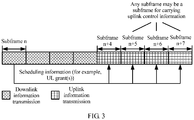
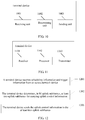
- multi-subframe scheduling signaling may be used to schedule a terminal device to transmit uplink data in multiple uplink subframes, as shown in FIG. 1 .
- the base station may trigger, by using one or more UL grants carried in a subframe n, one terminal device (for example, user equipment, User Equipment, UE) to transmit uplink data in a subframe n+4, n+5, n+6, or n+7.
- one terminal device for example, user equipment, User Equipment, UE
- the access network device and the terminal device if the access network device and the terminal device perform data transmission by using an unlicensed band resource, before data transmission, generally, the access network device and/or the terminal device needs to determine, by using a contention mechanism such as LBT, whether the unlicensed band resource can be used to perform data transmission.
- a contention mechanism such as LBT
- the terminal device may feed back channel state information (Channel State Information, CSI) or transmit a sounding reference signal (Sounding Reference Signal, SRS).
- the access network device may determine quality of a channel between the access network device and the terminal device by detecting the CSI or the SRS, and may further configure, based on the quality of the channel, a data transmission mode between the access network device and the terminal device, for example, set an appropriate modulation and coding scheme (Modulation and Coding Scheme, MCS), so as to maximally enhance data transmission efficiency while ensuring reliable data transmission.
- MCS Modulation and Coding Scheme
- Hybrid Automatic Repeat Request Hybrid Automatic Repeat Request
- the terminal device after the terminal device receives downlink data included in a physical downlink shared channel (Physical Downlink Shared Channel, PDSCH), the terminal device feeds back an acknowledgement (Acknowledgement, ACK) or a non-acknowledgement (Non-Acknowledgement, NACK) to the access network device.
- the access network may determine whether the downlink data corresponding to the feedback information is properly received, and therefore may properly perform a subsequent data transmission operation.
- the CSI, the SRS, and the HARQ-ACK may be carried in a scheduled uplink shared channel (Uplink Shared Channel, UL-SCH) for transmission.
- uplink scheduling information may schedule at least two uplink subframes, and the at least two uplink subframes both include the UL-SCH, how the terminal device determines a position for transmitting uplink control information such as the CSI, the SRS, or the HARQ-ACK is a problem to be considered.
- Embodiments of the present invention provide a method for transmitting uplink control information, so that an opportunity for reporting uplink control information can be ensured in a multi-sub frame scheduling scenario.
- a method for transmitting uplink control information includes:
- the uplink control information includes at least one of channel state information, a sounding reference signal, and a hybrid automatic repeat request acknowledgement.
- the scheduling information and the trigger information are carried in same downlink control information.
- both the scheduling information and the trigger information are carried in a UL grant.
- a terminal device includes:
- the uplink subframe determined by the determining unit is a last subframe in a time sequence of the M uplink subframes or a penultimate subframe in a time sequence.
- the receiving unit receives the scheduling information in a subframe n; and the determining unit is configured to determine a last or penultimate uplink subframe in a time sequence of an uplink burst included in the M uplink subframes as the uplink subframe for carrying the uplink control information, where the uplink burst refers to multiple uplink subframes that are occupied consecutively in time, and the uplink burst is after a downlink burst including the subframe n and is immediately adjacent to the downlink burst including the subframe n.
- a quantity of OFDM symbols for transmitting uplink information in the uplink subframe determined by the determining unit is not less than a specified threshold.
- the scheduling information and the trigger information are carried in same downlink control information.
- the uplink control information includes at least one of channel state information, a sounding reference signal, and a hybrid automatic repeat request acknowledgement.
- This embodiment of the present invention may be applied to an unlicensed spectrum system. Because the uplink subframe for carrying the uplink control information is a subframe other than the first uplink subframe, before transmitting the uplink control information, the terminal device can perform CCAs before at least two uplink subframes. As long as one CCA succeeds, the terminal device can send the uplink control information in the determined uplink subframe. This can maximally ensure an opportunity for transmitting the uplink control information, and further ensure reliable and efficient data transmission in an unlicensed band.
- a method for transmitting uplink control information includes:
- the uplink control information carried in the at least two uplink subframes is the same.
- the at least two uplink subframes include a first uplink subframe and a second uplink subframe, and uplink control information carried in the first uplink subframe is different from uplink control information carried in the second uplink subframe.
- a terminal device includes:
- the uplink control information carried in the at least two uplink subframes is the same.
- the at least two uplink subframes include a first uplink subframe and a second uplink subframe, and uplink control information carried in the first uplink subframe is different from uplink control information carried in the second uplink subframe.
- This embodiment of the present invention may be applied to an unlicensed spectrum system. Because the at least two subframes in the M uplink subframes for transmitting the uplink data are used to carry the uplink control information, the uplink control information can be fed back as soon as possible. Because the uplink control information is carried in multiple uplink subframes separately, occupancy of excessive uplink resources for uplink data transmission in a scheduled uplink subframe can be avoided.
- the present invention provides an embodiment of a method for transmitting uplink information.
- a method for transmitting uplink control information includes:
- a terminal device includes:
- a method for transmitting uplink control information includes:
- an access network device includes:
- different MCSs or RBs can be determined according to actual sizes of resources respectively used to transmit uplink data in different uplink subframes. Therefore, efficiency of using uplink resources in uplink subframes carrying only uplink data can be ensured while signaling overheads in multi-subframe scheduling are reduced.
- LTE Long Term Evolution
- GSM Global System for Mobile Communications
- UMTS Universal Mobile Telecommunications System
- CDMA Code Division Multiple Access
- a licensed-assisted access using LTE system is an LTE system in which a licensed band and an unlicensed band are used together in a CA or non-CA (for example, DC) mode.
- CA or non-CA for example, DC
- a mainstream deployment scenario of the licensed-assisted access using LTE system is a scenario in which a licensed band and an unlicensed band are jointly used through carrier aggregation CA.
- the licensed band or a carrier included in the licensed band or a cell working in the licensed band is used as a primary cell
- the unlicensed band or a carrier included in the unlicensed band or a cell working in the unlicensed band is used as a secondary cell.
- the primary cell and the secondary cell may be deployed on a same site, or may not be deployed on a same site, and an ideal backhaul path exists between the two cells.
- the present invention is not limited to the foregoing CA scenario.
- deployment scenarios including a scenario in which no ideal backhaul path exists between the two cells (primary cell and secondary cell). Because a backhaul delay is relatively long, information cannot be quickly coordinated between the two cells, for example, in a DC scenario.
- independent deployment of the cell working in the unlicensed band may be considered.
- the serving cell working in the unlicensed band can directly provide an independent access function, and does not require assistance from the cell working in the licensed band, for example, in a standalone LTE over unlicensed spectrum (Standalone U-LTE) system.
- one or more carriers may be included.
- Carrier aggregation is performed on the licensed band and the unlicensed band. This may include carrier aggregation performed on one or more carriers included in the licensed band and one or more carriers included in the unlicensed band.
- the cell mentioned in the present invention may be a cell corresponding to a base station.
- the cell may belong to a macro base station, or may belong to a base station corresponding to a small cell (small cell).
- Small cells herein may include a metro cell (Metro cell), a micro cell (Micro cell), a pico cell (Pico cell), a femto cell (Femto cell), and the like.
- the small cells have features of small coverage and low transmit power, and are used to provide high-speed data transmission services.
- multiple intra-frequency cells may simultaneously work in a carrier.
- concepts of the carrier and the cell are equivalent in the LTE system.
- a carrier index of the secondary carrier and a cell identity (Cell Identity, Cell ID) of a secondary cell working on the secondary carrier are both carried.
- Cell Identity, Cell ID a cell identity of a secondary cell working on the secondary carrier
- the concepts of the carrier and the cell are equivalent.
- accessing a carrier is equivalent to accessing a cell.
- DC and standalone U-LTE may also be based on this understanding.
- the concept of the cell is used for description.
- Network elements in the embodiments of the present invention include an access network device and a terminal device that may work in the unlicensed band.
- the terminal device may also be referred to as user equipment (UE, User Equipment), a mobile station, an access terminal, a subscriber unit, a subscriber station, a mobile station, a remote station, a remote terminal, a mobile device, a user terminal, a terminal, a wireless communications device, a user agent, or a user apparatus.
- UE User Equipment
- the terminal device may be a ST (STATION, station) in a WLAN (Wireless Local Area Network, wireless local area network), or may be a cellular phone, a cordless telephone, a SIP (Session Initiation Protocol, Session Initiation Protocol) phone, a WLL (Wireless Local Loop, wireless local loop) station, a PDA (Personal Digital Assistant, personal digital assistant), a handheld device or computing device that has a wireless communication function, or another processing device, in-vehicle device, or wearable device that is connected to a wireless modem, a mobile station in a future 5G network, a terminal device in a future evolved PLMN network, or the like.
- WLAN Wireless Local Area Network, wireless local area network
- SIP Session Initiation Protocol
- WLL Wireless Local Loop
- PDA Personal Digital Assistant
- the terminal device may further include a relay (Relay), another device capable of performing data communication with the access network device (for example, a base station), or the like.
- a relay Relay
- another device capable of performing data communication with the access network device for example, a base station
- the access network device may be a device configured to communicate with a mobile station.
- the access network device may be an AP (ACCESS POINT, access point) in a WLAN (Wireless Local Area Network, wireless local area network), a BTS (Base Transceiver Station, BTS) in GSM or CDMA (Code Division Multiple Access, Code Division Multiple Access), or an NB (NodeB, NodeB) in WCDMA, or may be an eNB or eNodeB (Evolved NodeB, evolved NodeB) in LTE (Long Term Evolution, Long Term Evolution), a relay station or an access point, an in-vehicle device, a wearable device, an access network device in a future 5G network, an access network device in a future evolved PLMN network, or the like.
- AP Access POINT
- WLAN Wireless Local Area Network, wireless local area network
- BTS Base Transceiver Station
- CDMA Code Division Multiple Access, Code Division Multiple Access
- NB NodeB, Node
- Uplink control information in the embodiments of the present invention is control information fed back by the terminal device to the access network device.
- the uplink control information may include channel state information CSI, a sounding reference signal SRS, or a hybrid automatic repeat request acknowledgement (Hybrid Automatic Repeat Request Acknowledgement, HARQ-ACK).
- the HARQ-ACK includes an acknowledgement ACK (Acknowledgement) or a negative acknowledgement NACK (Negative Acknowledgement), or may further include discontinuous transmission DTX (Discontinuous Transmission).
- the channel state information CSI may be preferably aperiodic CSI, but certainly also does not exclude periodic CSI.
- the CSI may further include at least one of a channel quality indicator (Channel Quality Indicator, CQI), a precoding indicator (Precoding Matrix Indicator, PMI), and a rank indicator (Rank Indicator, RI).
- CQI Channel Quality Indicator
- PMI Precoding Matrix Indicator
- RI rank indicator
- the CSI may be used to reflect quality of a channel between the access network device and the terminal device.
- the access network device may also determine quality of the channel between the access network device and the terminal device by detecting a received SRS. After determining the quality of the channel, the access network device may set an appropriate transmission mode based on the quality of the channel, so as to improve data transmission efficiency while ensuring reliable data transmission with the terminal device.
- the access network device may determine, by receiving a HARQ-ACK fed back by the terminal device, whether downlink data scheduled to the terminal device is properly received by the terminal device; and if determining that the scheduled data is properly received, the access network device may transmit new data; or if determining that the scheduled data is not properly received, the access network device may retransmit the data. This can ensure reliable transmission of the scheduled downlink data.
- duration of a sub frame is one millisecond (1 ms, 1 millisecond).
- a subframe includes 14 orthogonal frequency division multiplexing (Orthogonal Frequency Division Multiplexing, OFDM) symbols.
- OFDM Orthogonal Frequency Division Multiplexing
- a subframe includes 12 OFDM symbols.
- duration of a future subframe is equivalent to duration of a current OFDM symbol.
- a subframe may be denoted by a timeslot (Slot), or may be denoted by one or more (for example, a positive integer less than 7 or a positive integer less than 6) OFDM symbols.
- a subframe may be understood as a scheduled basic time unit.
- meanings of a subframe whose duration is N OFDM symbols and a transmission time interval (Transmission Time Interval, TTI) whose duration is N OFDM symbols may be consistent.
- N may be not greater than 14.
- TTI Transmission Time Interval
- duration used for information transmission in a subframe may be equal to duration of a subframe, or may be less than duration of a subframe. For example, if duration of a downlink subframe is 1 ms, duration used for downlink information transmission in the subframe may be equal to 1 ms, or may be less than 1 ms. For another example, if duration of an uplink subframe is 1 ms, duration used for uplink information transmission in the subframe may be equal to 1 ms, or may be less than 1 ms. Optionally, if duration of a subframe is 1 ms, when duration used for downlink information transmission in the subframe is less than 1 ms, the subframe may further include uplink information.
- the subframe further includes switching time used for uplink/downlink switching.
- the uplink/downlink switching time may be understood as the time for switching between downlink sending and uplink receiving; and for the terminal device, the uplink/downlink switching time may be understood as the time for switching between downlink receiving and uplink sending.
- the duration of the downlink subframe may be the same or different from the duration of the uplink subframe.
- uplink information corresponds to information sent by the terminal device to the access network device.
- the uplink information includes uplink data, an uplink reference signal, uplink control information, and information carried in a physical random access channel (Physical Random Access Channel, PRACH).
- the uplink data may correspond to data carried in a UL-SCH (or may be understood as uplink service data), and the uplink reference signal includes an uplink demodulation reference signal (Demodulation Reference Signal, DMRS).
- the uplink control information includes at least one of the following: channel state information (Channel State Information, CSI), a scheduling request (Scheduling Request, SR), a HARQ-ACK, and a sounding reference signal (Sounding Reference Signal, SRS).
- the SRS may be understood as a type of uplink control information.
- the uplink control information may be carried in a physical uplink control channel (Physical Uplink Control Channel, PUCCH), or may be carried in a physical uplink shared channel (Physical Uplink Shared Channel, PUSCH).
- PUCCH Physical Uplink Control Channel
- PUSCH Physical Uplink Shared Channel
- downlink information corresponds to information sent by the access network device such as an LTE base station to the terminal device.
- the downlink information may include data carried in a downlink physical channel, and/or a downlink reference signal.
- the downlink physical channel includes at least one of the following: a physical downlink shared channel (Physical Downlink Shared Channel, PDSCH), a physical broadcast channel (Physical Broadcast Channel, PBCH), a physical multicast channel (Physical Multicast Channel, PMCH), a physical control format indicator channel (Physical Control Format Indicator Channel, PCFICH), a physical downlink control channel (Physical Downlink Control Channel, PDCCH), a physical hybrid automatic repeat request indicator channel (Physical Hybrid ARQ Indicator Channel, PHICH), an enhanced physical downlink control channel (Enhanced Physical Downlink Control Channel, EPDCCH), and an MTC physical downlink control channel (MTC Physical Downlink Control Channel, MPDCCH).
- a physical downlink shared channel Physical Downlink Shared Channel
- PBCH Physical
- the downlink reference signal includes at least one of the following: a cell-specific reference signal (Cell-specific Reference Signal, CRS) a multimedia broadcast multicast service single frequency network reference signal (Multimedia Broadcast Multicast Service Single Frequency Network Reference Signal, MBSFN RS), a user equipment specific reference signal (UE-specific Reference Signal, DMRS) for demodulating data carried in the PDSCH, a reference signal (DeModulation Reference Signal, DMRS) for demodulating data carried in the EPDCCH or the MPDCCH, a positioning reference signal (Positioning Reference Signal, PRS), and a channel state information reference signal (CSI Reference Signal, CSI-RS).
- CRS Cell-specific Reference Signal
- MBSFN RS Multimedia Broadcast Multicast Service Single Frequency Network Reference Signal
- UE-specific Reference Signal User Equipment specific reference signal
- DMRS demodulating data carried in the PDSCH
- a reference signal DeModulation Reference Signal, DMRS
- PRS Positioning Reference Signal
- CSI Reference Signal channel state information reference signal
- Uplink data transmission in the LTE system is generally based on scheduling.
- the terminal device in the LTE system when data is transmitted in a physical uplink shared channel (Physical Uplink Shared Channel, PUSCH), occupied time-frequency resources (time resources and/or frequency resources) are indicated by the access network device such as a base station.
- the base station indicates, to the terminal device by using uplink grant (Uplink Grant, UL grant) control information, time-frequency resources occupied when the terminal device transmits uplink data.
- the access network device may schedule, by using multi-subframe scheduling signaling, the terminal device to transmit uplink data in multiple uplink subframes.
- the base station may schedule, in a subframe n by using one or more UL grants, the terminal device to transmit uplink data in the PUSCH included in multiple subframes.
- the base station may trigger, by using one or more UL grants carried in the subframe n, one terminal device (for example, user equipment, User Equipment, UE) to transmit uplink data in a subframe n+4, n+5, n+6, or n+7.
- the base station may instruct, by using trigger information included in uplink scheduling signaling (for example, the UL grant), the user equipment to feed back uplink control information.
- the scheduling signaling may schedule at least two uplink subframes, when the terminal device transmits uplink control information in a subframe for transmitting uplink data, how to determine the subframe for transmitting the uplink control information in the at least two uplink subframes is a problem urgently to be solved.
- the uplink control information is aperiodic CSI.
- a preconfigured time relationship exists between a subframe carrying aperiodic CSI and a subframe carrying trigger information for triggering aperiodic CSI reporting.
- FDD Frequency Division Duplex
- aperiodic CSI trigger indication information may be carried in a physical downlink control channel (Physical Downlink Control Channel, PDCCH) or an enhanced physical downlink control channel (Enhanced Physical Downlink Control Channel, EPDCCH)
- the aperiodic CSI trigger indication information may be understood as information included in a CSI request field (CSI request field) carried in the PDCCH or the EPDCCH
- the UE reports aperiodic CSI in a subframe n+4, and the aperiodic CSI is carried in an uplink resource indicated by a UL grant.
- UE receives uplink scheduling indication information (carried in a UL grant) in a subframe n, where the indication information includes aperiodic CSI trigger information
- the UE reports aperiodic CSI in a subframe n+k, where k is a positive integer, and a value of k is related to an uplink-to-downlink configuration of the TDD system and a value of n. Details are shown in the following Table 1.
- Table 1 using a TDD configuration 0 as an example, if the UE receives aperiodic CSI trigger signaling in a subframe 0, the UE reports aperiodic CSI in a subframe 4.
- Table 1 Values of k corresponding to TDD configurations 0 to 6 TDD UL/DL configuration Subframe index n 0 1 2 3 4 5 6 7 8 9 0 4 6 4 6 1 6 4 6 4 2 4 4 3 4 4 4 4 4 5 4 6 7 7 7 7 5
- the uplink subframe for reporting the CSI is in a position of a preconfigured uplink subframe, and the preconfigured uplink subframe is an uplink subframe nearest to the subframe n, among the subframe n+4 and subframes after the subframe n+4.
- the access network device and the terminal device perform data transmission by using an unlicensed band resource, before data transmission, generally, the access network device and/or terminal device need/needs to determine, by using a contention mechanism such as a CCA, whether the unlicensed band resource can be used to perform data transmission.
- a contention mechanism such as a CCA
- the UE transmits, in the subframe n+4, aperiodic CSI by using a PUSCH resource.
- the UE fails to obtain an unlicensed band resource through contention in the subframe n+4, according to the prior art, even if scheduled uplink resources still exist in subsequent subframes (for example, the subframe n+5, n+6, or n+7), the UE cannot transmit aperiodic CSI, and therefore, efficiency of downlink data transmission is affected.
- the present invention provides an embodiment of a method for transmitting uplink control information. This embodiment may be applied to a multi-subframe scheduling scenario in a U-LTE (LTE over unlicensed spectrum) system.
- U-LTE LTE over unlicensed spectrum
- the U-LTE system is an LTE system working in the unlicensed band, and may include an LTE system (LAA-LTE system) that uses a licensed band resource and an unlicensed band resource jointly in a CA mode, or may include an LTE system that uses a licensed band resource and an unlicensed band resource jointly in a dual connectivity (Dual Connectivity, DC) mode, or may include an LTE system (standalone U-LTE) that is independently deployed in an unlicensed band resource.
- LAA-LTE system LTE system that uses a licensed band resource and an unlicensed band resource jointly in a CA mode
- DC Dual Connectivity
- LTE system standalone U-LTE
- the present invention provides an embodiment of a method for transmitting uplink control information.
- the method may be applied to an LTE system working in an unlicensed band.
- the method includes the following steps.
- CCA Clear Channel Assessment
- the scheduling information is used to instruct the terminal device to transmit, in M uplink subframes, uplink data scheduled by the scheduling information
- the scheduling information may be used to indicate at least one of the following: a transmission format corresponding to the scheduled uplink data, for example, whether frequency hopping is required in a frequency position when the scheduled uplink data is transmitted in a corresponding time-frequency resource, resource allocation (Resource Allocation) corresponding to the scheduled uplink data, power control information corresponding to the scheduled uplink data, new transmission or retransmission information corresponding to the scheduled uplink data, or an MCS corresponding to the scheduled uplink data, where a quantity of uplink subframes corresponding to the scheduled uplink data may correspond to M in this embodiment of the present invention.
- resource allocation Resource Allocation
- the scheduling information may be one or some information fields included in downlink control information (Downlink Control Information, DCI), or may be all information fields included in DCI.
- DCI Downlink Control Information
- the scheduling information may be carried in a physical downlink control channel (Physical Downlink Control Channel, PDCCH) and/or an enhanced physical downlink control channel (Enhanced PDCCH, EPDCCH), or may be carried in another channel. This is not specifically limited in the present invention.
- the scheduling information may be UE-specific (UE specific) indication information, for example, effective only on a terminal device or a terminal device group.
- the scheduling information may also be cell-specific (Cell specific) indication information, for example, effective on all terminal devices in a connected mode in a cell or all terminal devices using the cell as a serving cell (including terminal devices in the connected mode and an idle mode).
- the scheduling information may be an information field included in uplink grant (Uplink Grant, UL grant) control information.
- the scheduling information may include at least one of the following: a carrier indicator (Carrier Indicator), a frequency hopping flag (Frequency hopping flag), resource block assignment and hopping resource allocation (Resource block assignment and hopping resource allocation), a modulation and coding scheme (Modulation and Coding Scheme, MCS), a redundancy version (Redundancy version, RV) indicator, a cyclic shift (Cyclic shift, CS) and an orthogonal cover code (Orthogonal Cover Code, OCC) corresponding to an uplink demodulation reference signal (Demodulation Reference Signal, DMRS), and a new data indicator (New data indicator, NDI).
- a carrier indicator Carrier Indicator
- Frequency hopping flag Frequency hopping flag
- resource block assignment and hopping resource allocation Resource block assignment and hopping resource allocation
- MCS Modulation and Coding Scheme
- RV redundancy version
- RV
- the scheduling information includes an information field included in control information that is transmitted in a DCI format 0 (DCI Format 0) or a DCI format 4 (DCI Format 4), or may further include an information field included in control information transmitted in an enhanced DCI format based on the DCI format 0 (referred to as a DCI format 0 enhanced format for ease of description) or an enhanced DCI format based on the DCI format 4 (likewise, referred to as a DCI format 4 enhanced format for ease of description).
- the DCI format 0 is used to instruct the terminal device to transmit, in an uplink subframe, uplink data scheduled by the DCI format 0, where the uplink data corresponds to one transport block (Transmission Block, TB) or corresponds to one codeword (Codeword); and the DCI format 4 is used to instruct the terminal device to transmit, in an uplink subframe, uplink data information scheduled by the DCI format 4, where the uplink data corresponds to two transport blocks TBs or corresponds to two codewords.
- FDD Frequency Division Duplex
- the DCI format 0 enhanced format may be understood as “necessary information fields are added based on the DCI format 0, so as to support scheduling of multiple uplink UL subframes simultaneously by using one piece of scheduling information".
- the DCI format 4 enhanced format may be understood as "necessary information fields are added based on the DCI format 4, so as to support scheduling of multiple uplink subframes simultaneously by using one piece of scheduling information, where each uplink subframe may support transmission of two transport blocks.
- the determined uplink subframe includes up to one subframe. Determining up to one uplink subframe for carrying the uplink control information may reduce resource overheads of the uplink control information.
- the scheduling information and the trigger information are carried in same downlink control information.
- both the scheduling information and the trigger information are carried in a UL grant.
- the scheduling information and the trigger information are carried in same downlink control information (Downlink Control Information, DCI).
- DCI Downlink Control Information
- the scheduling information and the trigger information are carried in one UL grant
- the UL grant is used to instruct the terminal device to transmit the uplink data and the uplink control information
- the trigger information may be an aperiodic CSI request (CSI request) included in the UL grant.
- the uplink control information is an SRS
- the trigger information may be an SRS request (SRS request) included in the UL grant.
- the trigger information may be understood as downlink data corresponding to the HARQ-ACK or PDSCH transmission corresponding to the HARQ-ACK.
- the terminal device may send, in a subframe n+4 according to a preconfigured HARQ timing relationship, a HARQ-ACK corresponding to the downlink data.
- the downlink data received in the subframe n or the PDSCH transmission detected in the subframe n may be understood as "the trigger information used to instruct the terminal device to send the uplink control information (HARQ-ACK)".
- the trigger information may be further understood as a downlink control channel corresponding to the HARQ-ACK, where the downlink control channel is defined as follows:
- the terminal device may receive, by detecting the downlink control channel, downlink data in a downlink data channel scheduled by the detected downlink control information.
- This embodiment of the present invention also does not exclude that the trigger information corresponding to the HARQ-ACK is indication information in another form, and does not exclude that the HARQ timing relationship is indicated by signaling.
- the scheduling information and the trigger information are carried in a same downlink subframe.
- the scheduling information and the trigger information used to instruct the terminal device to send the uplink control information are carried in a same subframe; or optionally, a subframe including the trigger information precedes a subframe including the scheduling information in a time sequence, and certainly, this also does not exclude that the subframe including the trigger information follows the subframe including the scheduling information and precedes the first uplink subframe in the M uplink sub frames in a time sequence.
- the uplink control information includes at least one of channel state information, a sounding reference signal, and a hybrid automatic repeat request acknowledgement.
- the scheduling information such as the UL grant is sent in the downlink subframe n.
- the terminal device receives the trigger information in the subframe n, and the trigger information instructs the terminal device to send the uplink control information, for example, aperiodic channel state information (Channel State Information, CSI).
- CSI Channel State Information
- the terminal device may determine to send the CSI in an uplink subframe in the subframe n+4, the subframe n+5, the subframe n+6, and the subframe n+7.
- the uplink subframe determined by the terminal device for transmitting the CSI may be a subframe other than the first uplink subframe in the subframe n+4 to the subframe n+7. That is, any one of the subframe n+5, the subframe n+6, and the subframe n+7 in FIG. 3 may be used as the uplink subframe for carrying the uplink control information.
- a subframe other than the first subframe is used to carry the uplink control information.
- the terminal device Before transmitting the uplink control information, the terminal device can perform CCAs before at least two uplink subframes; or the terminal device can perform a CCA before at least one uplink subframe in multiple uplink subframes including an uplink shared channel (Uplink Shared Channel, UL-SCH).
- the terminal device can send the uplink control information in the determined uplink subframe. This can maximally ensure an opportunity for transmitting the uplink control information, and further ensure reliable and efficient data transmission in the unlicensed band. For example, as shown in FIG.
- the terminal device may perform a CCA before at least one of multiple uplink subframes before determining that the unlicensed band is obtained through contention. For example, even if the terminal device fails to obtain an unlicensed band resource through contention in the subframe n+4, the subframe n+5, and the subframe n+6, the terminal device may still perform a CCA before the subframe n+7, and determine whether the uplink control information can be transmitted in the subframe n+7. Therefore, by adding an opportunity for the terminal device to contend for an unlicensed spectrum resource before the terminal device transmits the uplink control information, transmission of the uplink control information can be ensured maximally.
- the terminal device performs a CCA before at least one of multiple uplink subframes before sending the uplink control information in the determined uplink subframe, and the multiple uplink subframes are at least two uplink subframes included in the M uplink subframes.
- the terminal device may perform a CCA before at least one of the subframe n+4, the subframe n+5, and the subframe n+6.
- the terminal device may determine, in the M uplink subframes in multiple manners, the uplink subframe for carrying the uplink control information.
- Implementation 1 The terminal device determines a last subframe in the time sequence of the M uplink subframes or a penultimate subframe in the time sequence as the uplink subframe for carrying the uplink control information.
- the terminal device receives, in the subframe n, a UL grant sent by the access network device, where the UL grant instructs the terminal device to transmit the uplink data in the subframe n+4, the subframe n+5, the subframe n+6, and the subframe n+7, and the uplink data is carried in a PUSCH.
- the UL grant includes an aperiodic CSI request (CSI request), and the CSI request instructs the terminal device to transmit aperiodic CSI.
- the terminal device can determine, by performing a CCA, that an unlicensed band resource is obtained through contention in the subframe n+6 or the subframe n+7, the terminal device can transmit the aperiodic CSI in the subframe n+7, or transmit the aperiodic CSI in the subframe n+6.
- a benefit of transmitting the uplink control information in the last subframe in the time sequence is that an opportunity for transmitting the uplink control information can be ensured maximally. Even if the terminal device fails to obtain an unlicensed band resource through contention in the first scheduled uplink subframe, the terminal device may continue to assess whether any unlicensed band resource is available before transmitting data in subsequent uplink subframes.
- a subframe for carrying the aperiodic CSI report is configured or indicated in a relatively rear position in multiple scheduled uplink subframes if possible. This is equivalent to providing more CCA opportunities for subframes for carrying the aperiodic CSI report. Therefore, transmission of the aperiodic CSI report is ensured maximally.
- a benefit of transmitting the uplink control information in the penultimate subframe in the time sequence is that lossless transmission of the uplink control information in some cases can be ensured.
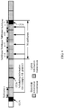
- the M uplink subframes may be followed by a downlink subframe, as shown in FIG. 4 .
- the access network device needs to first perform a CCA before performing downlink information transmission. To ensure that the downlink information transmission can start from a first OFDM symbol included in a downlink subframe, some time of the last uplink subframe before the downlink subframe cannot be used for uplink information transmission, so that the access network device can perform a CCA within the time, thereby ensuring that the downlink information transmission can start from the first OFDM symbol in the downlink subframe.
- the aperiodic CSI may be carried in the penultimate subframe in the M uplink subframes, for example, the subframe n+6 shown in FIG. 4 .
- scheduling information is used to instruct the terminal device to transmit, in M uplink subframes, uplink data scheduled by the scheduling information may include that the scheduling information is used to instruct the terminal device to transmit the uplink information within duration used for uplink information transmission in the M uplink sub frames.
- the terminal device receives the scheduling information in the subframe n; and the terminal device determines a last or penultimate uplink subframe in a time sequence of an uplink burst as the uplink subframe for carrying the uplink control information.
- the uplink burst refers to multiple uplink subframes that are occupied consecutively in time and included in the M uplink subframes, and the uplink burst is after a downlink burst including the subframe n and is immediately adjacent to the downlink burst including the subframe n.
- the terminal device determines any uplink subframe in the uplink burst as the uplink subframe for carrying the uplink control information, where the any uplink subframe is not the first uplink subframe in the M uplink subframes.
- the implementation 2 may be understood as "the terminal device receives the scheduling information in the subframe n; and the terminal device determines a last or penultimate uplink subframe in a time sequence of a first uplink burst as the uplink subframe for carrying the uplink control information".
- An uplink subframe set composed of the M uplink subframes includes the first uplink burst and a second uplink burst. The first uplink burst is after the downlink burst including the subframe n and is immediately adjacent to the downlink burst including the subframe n.
- the terminal device determines any uplink subframe in the time sequence of the first uplink burst as the uplink subframe for carrying the uplink control information, where the any uplink subframe does not include the first uplink subframe in the M uplink subframes.
- the uplink burst (Uplink Burst, UL burst) includes multiple uplink subframes that are occupied consecutively in time.
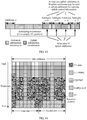
- the multiple uplink subframes may include a time area (for example, as shown in FIG. 5 ) used for a CCA, or may not include a time area (for example, as shown in FIG. 6 ) used for a CCA.
- an idle time unit may be at least used for performing a CCA by another terminal device.
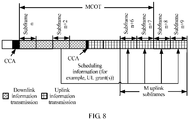
- the downlink burst refers to multiple downlink subframes that are occupied consecutively in time. Specifically, after a base station (such as an eNB) or a cell (Cell) within coverage of a base station preempts an unlicensed spectrum resource, the base station or the cell performs data transmission by using the unlicensed spectrum resource without using a contention mechanism such as a CCA. Duration of a downlink burst is not longer than maximum time of consecutive transmission by the base station (or the cell) on the unlicensed spectrum resource without using the contention mechanism, and the maximum time may also be referred to as maximum channel occupancy time (Maximum Channel Occupancy Time, MCOT).
- the MCOT may be related to constraints of regional laws and regulations.
- the MCOT may be equal to 4 ms; in Europe, the MCOT may be equal to 8 ms, 10 ms, or 13 ms.
- the MCOT may also be related to a contention mechanism used by a listening device (for example, the base station or user equipment). Generally, if listening time is shorter, the MCOT is shorter.
- a length of the MCOT may also be related to a service level of data transmission. For example, using a VoIP service as an example, a priority of the service is relatively high, and in this case, generally, the MCOT may be 2 ms, or may be 2 milliseconds consecutively after the base station obtains an unlicensed spectrum resource through contention. Using a data transmission service as an example, a priority of the service is relatively low, and generally, the MCOT may be 8 or 10 milliseconds consecutively.
- the terminal device receives, in a subframe n+3, the scheduling information sent by the access network device, and the scheduling information instructs the terminal device to transmit the uplink data in the subframe n+7, a subframe n+8, a subframe n+12, and a subframe n+13.
- An uplink burst including the subframe n+7 and the subframe n+8 is an uplink burst immediately adjacent to a downlink burst including the subframe n+3.
- An uplink burst including the subframe n+12 and the subframe n+13 is not an uplink burst immediately adjacent to the downlink burst including the subframe n+3.
- the uplink subframe for carrying the uplink control information may be the subframe n+8.
- a subframe n+x may be used to represent a subframe that has a specific relative relationship with the subframe n.
- the subframe n+x represents a subframe corresponding to the subframe n after a delay of x subframes.
- a benefit of using the implementation 2 is as follows: A benefit of carrying the uplink control information in an uplink burst nearest to the downlink burst including the subframe n+3 (the sub frame for carrying the scheduling information) is: the access network device can obtain the feedback information as soon as possible; because generally, a downlink burst follows the uplink burst, if the access network device receives, in the subframe n+7 or the subframe n+8, the uplink control information fed back by the terminal device, the access network device can set an appropriate MCS for downlink data in a next downlink burst according to the uplink control information, thereby enhancing efficiency of downlink data transmission on the unlicensed band resource.
- Implementation 3 The terminal device determines, in other subframes, a subframe in which a quantity of OFDM symbols for transmitting uplink information is not less than a specified threshold, as the uplink subframe for carrying the uplink control information.
- the other subframes are subframes other than the first subframe in the M uplink subframes.
- the specified threshold may include being not less than a quantity of OFDM symbols that can carry the uplink control information.
- the specified threshold may include 14 OFDM symbols.
- a benefit of this practice is that transmission efficiency of the uplink control information can be ensured; in addition, it may be further specified that a design criterion of an existing LTE system is reused for transmission of the uplink control information, so that system design is simplified.
- the terminal device may use a last uplink subframe in a time sequence of the multiple uplink subframes as the uplink subframe for carrying the uplink control information. For example, if a quantity of OFDM symbols for transmitting uplink information in the last uplink subframe (for example, the subframe n+7 in FIG.
- the terminal device may determine the penultimate uplink subframe in the time sequence of the M uplink subframes as the uplink subframe for carrying the uplink control information.
- the terminal device may determine, according to the scheduling information or other indication information, a quantity of OFDM symbols for transmitting uplink information in each scheduled uplink subframe, and may further determine a relationship between the quantity of OFDM symbols for transmitting uplink information and the specified threshold. If the determined quantity of OFDM symbols is not less than the specified threshold, the corresponding uplink subframe may be used to transmit uplink information. Further, the terminal device may use a first uplink subframe satisfying the relationship with the specified threshold, in the time sequence (time sequence relationship) of the determined uplink subframes, as the uplink subframe for transmitting the uplink control information, and a benefit of this practice is that the access network device can obtain the channel state information earlier.
- the terminal device may use a last uplink subframe satisfying the relationship with the specified threshold, in the time sequence of the determined uplink subframes, as the uplink subframe for transmitting the uplink control information, and a benefit of this practice is that an opportunity for transmitting the uplink control information can be ensured, as described above.
- the access network device sends the scheduling information by using the subframe n
- the terminal device can obtain an unlicensed band resource through contention before the subframe n+4. Therefore, uplink data that is scheduled by the scheduling information sent by the access network device with respect to the subframe n+5 to the subframe n+7 may be transmitted in 14 OFDM symbols.
- the terminal device may determine that quantities of OFDM symbols for transmitting uplink information in the subframe n+5 to the subframe n+7 are not less than the specified threshold (for example, 14 OFDM symbols). In this case, any one of the subframe n+5 to the subframe n+7 may be used as the uplink subframe for carrying the uplink control information in this embodiment of the present invention. Still with reference to FIG. 4 , when the access network device sends the scheduling information by using the subframe n, it may be assumed that the terminal device can obtain an unlicensed band resource through contention before the subframe n+4; in addition, it is considered that the access network device needs to send downlink information after the subframe n+7.
- the specified threshold for example, 14 OFDM symbols
- a quantity of OFDM symbols for transmitting uplink information in the subframe n+7 is less than 14. Therefore, uplink data that is scheduled by the scheduling information sent by the access network device with respect to the subframe n+5 and the subframe n+6 may be transmitted in 14 OFDM symbols, but uplink data that is scheduled by the scheduling information sent with respect to the subframe n+7 can be transmitted only in a part of OFDM symbols.
- the terminal device may determine that quantities of OFDM symbols for transmitting uplink information in the subframe n+5 and the subframe n+6 are not less than the specified threshold, but the quantity of OFDM symbols for transmitting uplink information in the subframe n+7 is less than the specified threshold. In this case, the terminal device may determine the subframe n+6 as the uplink subframe for carrying the uplink control information.
- the specified threshold may be specified by a standard protocol, or notified by using higher layer signaling.
- the higher layer signaling includes radio resource control (Radio Resource Control, RRC) signaling, or includes Medium Access Control (Medium Access Control, MAC) signaling.
- RRC Radio Resource Control
- MAC Medium Access Control
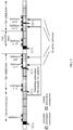
- Implementation 4 The terminal device receives the scheduling information in the subframe n; and the terminal device determines, in the M uplink subframes except the first subframe, any uplink subframe within same maximum channel occupancy time (Maximum Channel Occupancy Time, MCOT) as the subframe n, as the uplink subframe for carrying the uplink control information.
- MCOT Maximum Channel Occupancy Time
- the terminal device may determine, in the M uplink subframes except the first subframe, a last or penultimate uplink subframe within the same MCOT as the subframe n, as the uplink subframe for carrying the uplink control information; or optionally, the terminal device may determine, in the M uplink subframes except the first subframe, a last or penultimate uplink subframe in a time sequence of uplink subframes that are within the same MCOT as the subframe n and in which quantities of OFDM symbols for transmitting uplink information are not less than a specified threshold, as the uplink subframe for carrying the uplink control information.
- a time range included in the MCOT starts from a subframe start boundary of the subframe n and ends at a sub frame start boundary of a sub frame n+8.
- the terminal device receives the scheduling information in a subframe n+2, where the scheduling information instructs the terminal device to transmit the uplink data in the subframe n+6, the subframe n+7, the subframe n+8, and a subframe n+9, in the implementation 4, the terminal device may determine the subframe n+7 as the uplink subframe for carrying the uplink control information.
- the terminal device may use a CCA of a high priority within the MCOT. Therefore, the terminal device can obtain an unlicensed band resource through contention more easily, thereby further ensuring transmission of the uplink control information.
- the CCA of the high priority can be used to obtain an unlicensed band resource more easily.
- the CCA of the high priority may be LBT not including a random backoff parameter, for example, one-shot LBT.
- Implementation 5 The terminal device receives the scheduling information in the subframe n; and the terminal device determines, in the M uplink subframes except the first subframe, any subframe that does not require a clear channel assessment (CCA), as the uplink subframe for carrying the uplink control information.
- CCA clear channel assessment
- the determined uplink subframe for carrying the uplink control information is a first uplink subframe in a time sequence of uplink subframes that do not require CCAs.
- the determined uplink subframe for carrying the uplink control information is a first uplink subframe in a time sequence of uplink subframes that do not require CCAs and in which quantities of OFDM symbols for transmitting uplink information are not less than the specified threshold.
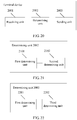
- the terminal device receives, in a subframe n+3, the scheduling information sent by the access network device, and the scheduling information instructs the terminal device to transmit the uplink data in the subframe n+7, a subframe n+8, a subframe n+12, and a subframe n+13.
- the terminal device may transmit uplink information by direct using an unlicensed band resource without performing a CCA.
- duration of uplink information transmission performed without a CCA is generally limited, for example, is 1 ms. Therefore, when the terminal device transmits scheduled uplink data in the subframe n+13, the terminal device needs to determine, by performing a CCA, whether an unlicensed band resource is available.
- the terminal device may determine the uplink subframe n+12 as the uplink subframe for carrying the uplink control information.
- a benefit of this practice is: the terminal device does not need to perform a CCA to determine whether uplink information can be transmitted in the subframe n+12; conversely, the terminal device can transmit the uplink control information directly by using the subframe n+12, and therefore, an opportunity for transmitting the uplink control information can be ensured.
- FIG. 9 although a CCA corresponding to the uplink subframe n+8 is not included, whether the CCA corresponding to the uplink subframe n+8 exists depends on whether the terminal device can obtain an unlicensed band resource through contention in the uplink subframe n+7.
- the terminal device obtains an unlicensed band resource through contention in the uplink subframe n+7, the CCA corresponding to the uplink subframe n+8 does not exist. Conversely, if the terminal device fails to obtain an unlicensed band resource through contention in the subframe n+8, the CCA corresponding to the uplink subframe n+8 exists. In other words, there is a probability that the CCA corresponding to the uplink subframe n+8 does not exist. It is stressed that, in the implementation 5, the CCA corresponding to the uplink subframe for carrying the uplink control information is determined as nonexistent. Therefore, in the implementation 5, the uplink subframe n+8 is an uplink subframe that is not suitable for carrying the uplink control information.
- the CCA corresponding to the uplink subframe exists means that before the terminal device transmits uplink information in the uplink subframe, the terminal device first needs to determine, by performing the CCA, whether an unlicensed band resource is available. That the CCA corresponding to the uplink subframe does not exist means that before the terminal device transmits uplink information in the uplink subframe, the terminal device can directly use an unlicensed band resource, without determining availability of the unlicensed band resource by performing the CCA.
- the implementation 1, the implementation 2, the implementation 4, or the implementation 5 may be used in combination with the implementation 3.
- the last subframe in the time sequence of the M uplink subframes or the penultimate subframe in the time sequence when the quantity of OFDM symbols for transmitting uplink information is not less than the specified threshold, may be used as the uplink subframe for carrying the uplink control information.
- the last or penultimate uplink subframe in the time sequence of the uplink burst when the quantity of OFDM symbols for transmitting uplink information is not less than the specified threshold, may be used as the uplink subframe for carrying the uplink control information.
- any one of the M uplink subframes except the first subframe, within the same MCOT as the downlink subframe including the scheduling information, when the quantity of OFDM symbols for transmitting uplink information is not less than the specified threshold, may be used as the uplink subframe for carrying the uplink control information.
- any subframe that does not require a clear channel assessment (CCA), in the M uplink subframes except the first uplink subframe, when the quantity of OFDM symbols for transmitting uplink information is not less than the specified threshold may be used as the uplink subframe for carrying the uplink control information.
- CCA clear channel assessment
- the hidden node herein includes a node (the node is sending data) that the terminal device fails to listen to in a CCA process when a CCA needs to be performed before the terminal device sends uplink information to the access network device. If data sent by the node causes interference to reception when the access network device receives the uplink information sent by the terminal device, this node may be considered as a hidden node for the terminal device.
- the access network device may send indication information, where the indication information indicates the uplink subframe for carrying the uplink control information, and the uplink subframe is a subframe other than the first subframe in the M uplink subframes.
- the uplink subframe has features defined by the foregoing embodiment of the terminal device.
- the present invention provides a terminal device.
- the terminal device may be applied to a multi-sub frame scheduling scenario in a U-LTE system, and the terminal device may perform each step in the foregoing method embodiment.
- the terminal device includes:
- the uplink subframe determined by the determining unit is a last subframe in a time sequence of the M uplink subframes or a penultimate subframe in a time sequence.
- the receiving unit receives the scheduling information in a subframe n; and the determining unit is configured to determine a last or penultimate uplink subframe in a time sequence of an uplink burst included in the M uplink subframes as the uplink subframe for carrying the uplink control information, where the uplink burst refers to multiple uplink subframes that are occupied consecutively in time, and the uplink burst is after a downlink burst including the subframe n and is immediately adjacent to the downlink burst including the subframe n.
- a quantity of OFDM symbols for transmitting uplink information in the uplink subframe determined by the determining unit is not less than a specified threshold.
- the scheduling information and the trigger information are carried in same downlink control information.
- the uplink control information includes at least one of channel state information, a sounding reference signal, and a hybrid automatic repeat request acknowledgement.
- the scheduling information For definitions and functions of the scheduling information, the trigger information, the uplink control information, and the M uplink subframes in the terminal device embodiment, refer to related descriptions in the foregoing method embodiment.
- the terminal device includes:
- the uplink subframe determined by the determining unit is a last subframe in a time sequence of the M uplink subframes or a penultimate subframe in a time sequence.
- the receiving unit receives the scheduling information in a subframe n; and the determining unit is configured to determine a last or penultimate uplink subframe in a time sequence of an uplink burst included in the M uplink subframes as the uplink subframe for carrying the uplink control information, where the uplink burst refers to multiple uplink subframes that are occupied consecutively in time, and the uplink burst is after a downlink burst including the sub frame n and is immediately adjacent to the downlink burst including the sub frame n.
- a quantity of OFDM symbols for transmitting uplink information in the uplink subframe determined by the determining unit is not less than a specified threshold.
- the scheduling information and the trigger information are carried in same downlink control information.
- the uplink control information includes at least one of channel state information, a sounding reference signal, and a hybrid automatic repeat request acknowledgement.
- the scheduling information For definitions and functions of the scheduling information, the trigger information, the uplink control information, and the M uplink subframes in the terminal device embodiment, refer to related descriptions in the foregoing method embodiment.
- the present invention provides an embodiment of a method for transmitting uplink control information. This embodiment may be applied to a multi-subframe scheduling scenario in a U-LTE (LTE over unlicensed spectrum) system.
- U-LTE LTE over unlicensed spectrum
- the U-LTE system is an LTE system working in the unlicensed band, and may include an LTE system (LAA-LTE system) that uses a licensed band resource and an unlicensed band resource jointly in a CA mode, or may include an LTE system that uses a licensed band resource and an unlicensed band resource jointly in a dual connectivity (Dual Connectivity, DC) mode, or may include an LTE system (standalone U-LTE) that is independently deployed in an unlicensed band resource.
- LAA-LTE system LTE system that uses a licensed band resource and an unlicensed band resource jointly in a CA mode
- DC Dual Connectivity
- LTE system standalone U-LTE
- the present invention provides an embodiment of a method for transmitting uplink control information.
- the method may be applied to an LTE system working in an unlicensed band.
- the method includes the following steps.
- a terminal device receives scheduling information and trigger information from an access network device, where the scheduling information is used to instruct the terminal device to transmit, in M uplink subframes, uplink data scheduled by the scheduling information, M is a positive integer not less than 2, and the trigger information is used to instruct the terminal device to send uplink control information.
- the terminal device determines, in the M uplink subframes, at least two uplink subframes for carrying the uplink control information.
- the terminal device sends the uplink control information in the at least two uplink subframes.
- scheduling information For definitions and functions of the scheduling information, the trigger information, and the uplink control information in this embodiment, refer to related descriptions in Embodiment 1. Details are not further described herein.
- the scheduling information and the trigger information are carried in same downlink control information.
- both the scheduling information and the trigger information are carried in a UL grant.
- the scheduling information and the trigger information are carried in a same downlink subframe.
- the scheduling information and the trigger information used to instruct the terminal device to send the uplink control information are carried in a same subframe; or optionally, a subframe including the trigger information precedes a subframe including the scheduling information in a time sequence, and certainly, this also does not exclude that the subframe including the trigger information follows the subframe including the scheduling information and precedes a first uplink subframe in the M uplink subframes in a time sequence.
- the uplink control information can be fed back as soon as possible; and/or because the uplink control information is carried in multiple uplink subframes separately, occupancy of excessive uplink resources for uplink data transmission in a scheduled uplink subframe can be avoided.
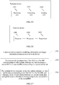
- a diagram of a relationship between subframes in multi-subframe scheduling shown in FIG. 13 is used as an example to describe a specific implementation of this embodiment of the present invention. It is assumed that the terminal device receives, in a subframe n, uplink scheduling grant UL grant information sent by the access network device, where the information schedules the terminal device to send scheduled uplink data in a subframe n+4, a subframe n+5, a subframe n+6, and a subframe n+7, and the uplink data is carried in a PUSCH. In this case, any two of the subframe n+4, the subframe n+5, the subframe n+6, and the subframe n+7 may be used to transmit the uplink control information.
- the terminal device may further determine, in the subframe n+5, whether an unlicensed band resource is obtained through contention, and further determine whether uplink control information can be transmitted in the subframe n+5.
- the terminal device may transmit uplink control information in the subframe n+4, and the terminal device continues to transmit uplink control information in the subframe n+5.
- the terminal device before the terminal device transmits uplink information in any one of the M uplink subframes, the terminal device needs to determine, by performing a CCA, whether an unlicensed band resource can be obtained through contention.
- the terminal device before the terminal device transmits uplink information in the first uplink subframe in the M uplink subframes, the terminal device needs to determine, by performing a CCA, whether an unlicensed band resource can be obtained through contention.
- whether a CCA needs to be performed to determine whether an unlicensed band resource can be obtained through contention depends on whether an unlicensed band resource is obtained through contention in a CCA corresponding to an uplink subframe before the other uplink subframe.
- whether the terminal device needs to perform a CCA to determine availability of an unlicensed band resource before transmitting uplink information in the subframe n+5 depends on whether the terminal device obtains an unlicensed band resource through contention in the subframe n+4. If the terminal device obtains an unlicensed band resource through contention before transmitting uplink information in the subframe n+4 (which may be understood as "the terminal device obtains an unlicensed band resource through contention in the subframe n+4), the terminal device may not need to perform a CCA to contend for an unlicensed band resource before transmitting uplink information in the subframe n+5.
- the terminal device fails to obtain an unlicensed band resource through contention before transmitting uplink information in the subframe n+4 (which may be understood as "the terminal device fails to obtain an unlicensed band resource through contention in the subframe n+5)
- the terminal device needs to perform a CCA to contend for an unlicensed band resource before transmitting uplink information in the subframe n+5.
- whether the terminal device needs to perform a CCA to determine availability of an unlicensed band resource before transmitting uplink information in the subframe n+6 may depend on whether the terminal device obtains an unlicensed band resource through contention in the subframe n+4 and/or the subframe n+5.
- the terminal device may determine, in the M uplink subframes in multiple manners, the at least two uplink subframes for carrying the uplink control information.
- the terminal device determines any two uplink subframes in the uplink burst as uplink subframes included in the at least two uplink subframes, where neither of the any two uplink subframes is the first uplink subframe in the M uplink subframes.
- implementation 1 to the implementation 6 may be used in combination.
- the method for determining the at least two uplink subframes is similar to the method for determining the uplink subframe for carrying the uplink control information in Embodiment 1.
- the implementation 5 and the implementation 6 refer to related descriptions in Embodiment 1. Details are not further described herein.
- the uplink control information carried in each of the at least two uplink subframes is the same.
- the at least two uplink subframes include a first uplink subframe and a second uplink subframe, and uplink control information carried in the first uplink subframe is different from uplink control information carried in the second subframe.
- content of the uplink control information carried in the first uplink subframe does not coincide with content of the uplink control information carried in the second subframe, or content of the control information carried in the first uplink subframe includes content of the uplink control information carried in the second subframe.
- the uplink control information is aperiodic CSI.
- CSI including periodic CSI and aperiodic CSI
- a rule for transmitting CSI in a scheduled uplink resource (it may be understood that the CSI is carried in a PUSCH) in the prior art is described.
- an FDD system is used as an example for description. It should be noted that, a difference between a TDD system and an FDD system in CSI transmission mainly lies in that not all subframes in the TDD system are uplink subframes for transmitting uplink information, and this causes CSI transmission time positions to be different.
- the CSI includes two types: periodic CSI and aperiodic CSI.
- the periodic CSI may be carried in a physical uplink control channel (Physical Uplink Control Channel, PUCCH), or may be carried in the PUSCH.
- the aperiodic CSI is carried in the PUSCH, and is triggered by aperiodic CSI trigger indication information. A case in which the CSI is carried in the PUSCH is mainly considered in this embodiment of the present invention.
- the data transmission may include sending data to the access network device by using the CC1, or may include receiving data sent by the access network device by using the CC1. If the terminal device receives, in a subframe k-4, uplink scheduling information (UL grant) sent by the access network device, the terminal device may transmit scheduled uplink data in a subframe k.
- UL grant uplink scheduling information
- the terminal device may transmit the CSI by using a scheduled uplink resource in the subframe k.
- the terminal device may perform data transmission with the access network device by using multiple carriers. For example, the terminal device may perform data transmission with the access network device by using a CC1, a CC2, a CC3, and a CC4 simultaneously.
- the terminal device feeds back, according to a preset rule, CSI information corresponding to a carrier or a serving cell. If the terminal device receives, in a subframe k-4 of the CC1, uplink scheduling information (UL grant) sent by the access network device, the terminal device may transmit uplink data in a subframe k of the CC1.
- UL grant uplink scheduling information
- the terminal device transmits, according to a preset rule (for example, as described in the following Table 1), in an uplink resource scheduled in the subframe k, the CSI of the serving cell corresponding to the CSI request indication information.
- a preset rule for example, as described in the following Table 1
- the concept of the serving cell is consistent with the concept of the carrier.
- the CSI request field may include two bits, and different combinations of the two bits may be used to indicate four different states.
- the terminal device may transmit, in the subframe k of the CC1 with reference to the foregoing example, CSI corresponding to each serving cell included in a second set of serving cells.
- a first set of serving cells (1st set of serving cells) includes the CC1 and the CC2
- the second set of serving cells (2nd set of serving cells) includes the CC3 and the CC4.
- the terminal device transmits, in the subframe k, CSI corresponding to the CC3 and the CC4.
- a feedback period of CSI corresponding to each downlink carrier (for example, the CC1, the CC2, the CC3, or the CC4) that is also referred to as a serving cell, is configured independently.
- the terminal device transmits the CSI in a determined carrier or serving cell according to a preset rule. For example, according to the preset rule, the terminal device selects a serving cell configured with a smallest cell index (Cell Index), for transmitting the CSI.
- Cell Index a cell index
- the terminal device may further determine, according to a correspondence between bit states included in the aperiodic CSI trigger indication information (CSI request field) and serving cells, to report CSI of the serving cells, the terminal device may further determine, according to a correspondence between bit states included in the CSI request field and a CSI process (CSI process(es)) configured by higher layers, to report CSI corresponding to the CSI process(es), or determine, for a specific serving cell, to report CSI corresponding to a CSI process of the serving cell; or the terminal device may further determine, according to a correspondence between a bit state included in the CSI request field and a CSI process(es) and/or ⁇ CSI process(es), CSI subframe set ⁇ -pair(s) configured by higher layers, to report CSI corresponding to the CSI process(es) and/or ⁇ CSI process(es), CSI subframe set ⁇ -pair(s).
- CSI process(es) CSI process(es)
- the UCI herein may include a HARQ-ACK and CSI
- the HARQ-ACK includes an ACK or a NACK
- the CSI includes a CQI, a PMI, and a RI.
- a PRB pair is a time-frequency resource composed of one subframe in time and resource elements (Resource Element, RE) included in 12 subcarriers in frequency.
- RE Resource Element
- a time-frequency resource is divided into OFDM symbols in a time domain dimension and OFDM subcarriers in a frequency domain dimension, and a smallest resource granularity is referred to as a RE, that is, it represents a time-frequency grid of one OFDM symbol in a time domain and one OFDM subcarrier in a frequency domain.
- a quantity of resource elements occupied by the CSI in the scheduled uplink resource may be determined according to an offset indication configured by higher layers, a quantity of time-frequency resources allocated for uplink data transmission, a quantity of information bits in uplink data transmission, and a quantity of information bits to be transmitted in the CSI.
- the offset indication configured by the higher layers may include I offset RI or I offset , MC RI .
- the terminal device may determine a value of ⁇ offset RI according to this index, and further determine a quantity of time-frequency resources that need to be occupied for transmitting the RI.
- the offset indication may include I offset CQI or I offset , MC CQI .
- the terminal device may determine a value of ⁇ offset CQI according to this index indication, and further determine a quantity of time-frequency resources that need to be occupied for transmitting the CQI (including the PMI). Still with reference to a position of the CSI in the scheduled uplink resource in FIG. 14 , REs in which the CSI should be transmitted may be determined.
- a modulation and coding scheme (Modulation and Coding Scheme, MCS) corresponding to the uplink data needs to correspond to the uplink resource used by the terminal device for transmitting the uplink data.
- MCS Modulation and Coding Scheme
- the uplink control information carried in each of the at least two uplink subframes is the same.
- uplink control information carried in the two subframes is the same.
- the terminal device determines, according to the indication of the CSI request field, that CSI corresponding to the second set of serving cells needs to be fed back, the terminal device feeds back, in both the subframe n+6 and the subframe n+7, the CSI corresponding to the second set of serving cells.
- a UL grant included in a downlink subframe may schedule the terminal device to transmit scheduled uplink data in at least two uplink subframes.
- some information fields included in the UL grant may be reused for multiple scheduled uplink subframes, that is, one set of information fields is used. For example, resource allocation (resource assignment), a cyclic shift (Cyclic shift) corresponding to a demodulation reference signal DMRS, and an MCS included in the UL grant and corresponding to different scheduled uplink subframes are the same.
- resources used for uplink data transmission in an uplink subframe including CSI are fewer than resources used for uplink data transmission in an uplink subframe not including CSI.
- the MCS needs to be set based on uplink resources actually used for uplink data transmission in an uplink subframe including CSI. Therefore, for the uplink subframes that do not include CSI transmission, because many uplink resources are actually used for uplink data transmission, given the same MCS, redundant uplink resources exist in the uplink subframes not including CSI transmission, and uplink resource waste is caused.
- all the scheduled multiple uplink subframes may include CSI.
- This issue is also effective on uplink control information that is an SRS or a HARQ-ACK.
- uplink time-frequency resources used for uplink data transmission in an uplink subframe including an SRS are different from uplink time-frequency resources used for uplink data transmission in an uplink subframe not including an SRS
- uplink time-frequency resources used for uplink data transmission in an uplink subframe including a HARQ-ACK are different from uplink time-frequency resources used for uplink data transmission in an uplink subframe not including a HARQ-ACK.
- the at least two uplink subframes include the first uplink subframe and the second uplink subframe, the uplink control information carried in the first uplink subframe is different from the uplink control information carried in the second subframe, and the content of the uplink control information carried in the first uplink subframe does not coincide with the content of the uplink control information carried in the second subframe.
- An advantage of using this manner is: not only relatively low control signaling overheads can be ensured, but also relatively few resources can be reserved for CSI transmission in an uplink subframe including CSI transmission, because different CSI information is allocated to different uplink subframes. This may further reduce uplink resource waste.
- that transmitted CSI is different includes at least one of the following: content of the transmitted CSI is different, serving cells corresponding to the transmitted CSI are different, CSI processes corresponding to the transmitted CSI are different, or subframe sets corresponding to the transmitted CSI are different.
- the content of the transmitted CSI includes at least one of a CQI, a PMI, or a RI.
- That the content of the transmitted CSI information does not coincide means that the uplink control information carried in the first uplink subframe is completely different from the uplink control information carried in the second uplink subframe.
- the terminal device may transmit one of a RI, a CQI, or a PMI in the subframe n+6 and the subframe n+7, and the CSI information transmitted by the terminal device in the subframe n+6 and the subframe n+7 is different.
- the CQI or the PMI is transmitted in the subframe n+6, and the RI is transmitted in the subframe n+7; or considering a priority of uplink control information included in the CSI, the RI may be transmitted in the subframe n+6, and the CQI is transmitted in the subframe n+7.
- the terminal device may transmit data to the access network device simultaneously by using the CC1, the CC2, the CC3, or the CC4; and according to the higher layer configuration, the first set of serving cells (1st set of serving cells) includes the CC1 and the CC2, and the second set of serving cells (2nd set of serving cells) includes the CC3 and the CC4.
- the terminal device may determine that CSI corresponding to the second set of serving cells needs to be fed back.
- the terminal device may feed back, in the first uplink subframe (for example, the subframe n+6), CSI corresponding to the CC3, and feed back, in the second uplink subframe (for example, the subframe n+7), CSI corresponding to the CC4; or the terminal device may feed back, in the first uplink subframe, CSI corresponding to the CC3 and CC4, and feed back, in the second uplink subframe, CSI corresponding to the CC1 and the CC2; or the terminal device may feed back, in the first uplink subframe, RIs corresponding to the CC3 and the CC4, and feed back, in the second uplink subframes, CQIs or PMIs corresponding to the CC3 and the CC4; or the terminal device may feed back, in the first uplink subframe, RIs corresponding to the CC1 to the CC4, and feed back, in the second uplink subframe, CQIs or PMIs corresponding to the CC1 to the CC4; or
- the terminal device may add, to different uplink subframes respectively, CSI corresponding to CSI processes and triggered for reporting. For example, assuming that six CSI processes are configured by higher layers for the terminal device, the terminal device may determine, according to a correspondence specified in Table 3, reporting for CSI processes corresponding to different CSI request field indications. Assuming that the CSI request field is '100', according to the correspondence in Table 3, the terminal device determines that CSI corresponding to a third set of CSI process(es) needs to be reported.
- CSI processes CSI processes
- the terminal device may add to different uplink subframes according to each CSI process included in the third set of CSI processes or according to another rule (for example, the third set of CSI processes is divided into groups, where one group includes two CSI processes).
- the third set of CSI processes is divided into groups, where one group includes two CSI processes.
- a set composed of a RI corresponding to each CSI process is transmitted in the first uplink subframe, and a set composed of a CQI or a PMI corresponding to each CSI process is transmitted in the second uplink subframe.
- CSI corresponding to the third set of CSI processes is transmitted in one uplink subframe, and then CSI corresponding to another set of CSI processes is transmitted in another uplink subframe according to a preset rule. For example, CSI corresponding to a fourth set of CSI processes is transmitted in another uplink subframe.
- the at least two uplink subframes include the first uplink subframe and the second uplink subframe, and the uplink control information carried in the first uplink subframe is different from the uplink control information carried in the second uplink subframe.
- the content of the control information carried in the first uplink subframe includes the content of the uplink control information carried in the second uplink subframe.
- that the content of the control information carried in the first uplink subframe includes the content of the uplink control information carried in the second subframe includes: CSI information carried in the second uplink subframe is a proper subset of CSI information carried in the first uplink subframe.
- a benefit of using this embodiment is: resource waste is reduced maximally, and it is ensured that the terminal device does not lose excessive CSI information if the terminal device fails to obtain an unlicensed band resource through contention in an uplink subframe for CSI transmission due to a CCA.
- an uplink subframe subsequent in time may be used to transmit more CSI information.
- the at least two uplink subframes include the first uplink subframe and the second uplink subframe, and the uplink control information carried in the first uplink subframe is different from the uplink control information carried in the second uplink subframe.
- some content of the control information carried in the first uplink subframe is the same as some content of the uplink control information carried in the second uplink subframe.
- the same content may be uplink control information of a higher priority, for example, a RI.
- a benefit of using this embodiment is: resource waste is reduced maximally, and transmission of the uplink control information of the higher priority is ensured.
- which subframes are specifically determined for transmitting CSI information and which content is included in CSI transmitted in each determined subframe may be preconfigured, or may be notified by using signaling. This is not specifically limited in this embodiment of the present invention.
- the uplink control information carried in each of the at least two uplink subframes is the same may be understood as "time positions (which may be indicated by OFDM symbol indexes) and frequency resource positions occupied by SRSs transmitted in the at least two uplink subframes, and used sequences are all the same”; "the at least two uplink subframes include the first uplink subframe and the second uplink subframe, and the uplink control information carried in the first uplink subframe is different from the uplink control information carried in the second uplink subframe” may be understood as "at least one of the following included in the SRSs transmitted by the terminal device in the first uplink subframe and the second uplink subframe is different: time positions occupied by the SRSs (which may be indicated by OFDM symbol indexes), frequency resource positions occupied for transmitting the SRSs, or sequences used by the SRSs”, or may be understood as "a frequency
- the implementation described above is also applicable to a hybrid automatic repeat request acknowledgement (HARQ-ACK).
- HARQ-ACK hybrid automatic repeat request acknowledgement
- the HARQ-ACK fed back by the terminal device may be intended for multiple uplink subframes and multiple serving cells.
- the uplink control information carried in each of the at least two uplink subframes is the same may be understood as “HARQ-ACK information carried in each uplink subframe included in the at least two uplink subframes is the same”; “the at least two uplink subframes include the first uplink subframe and the second uplink subframe, and the uplink control information carried in the first uplink subframe is different from the uplink control information carried in the second uplink subframe” may be understood as "at least one of the following included in the HARQ-ACKs transmitted by the terminal device in the first uplink subframe and the second uplink subframe is different: different uplink subframes corresponding to the HARQ-ACKs, or different serving cells corresponding to the HARQ-ACKs; and “the at least two uplink subframes include the first uplink subframe and the second uplink subframe, and the uplink control information carried in the first uplink subframe is different from the uplink control information carried in the second uplink subframe” may also be understood as "
- the access network device may send indication information, where the indication information indicates the uplink subframes for carrying the uplink control information, and the uplink subframes are at least two uplink subframes in the M uplink subframes.
- the uplink subframes have features defined by the foregoing implementation 1 to the implementation 6.
- the access network device may further send indication information to the terminal device, where the indication information is used to indicate which uplink control information is carried in the uplink subframes for carrying the uplink control information.
- the present invention provides a terminal device.
- the terminal device may be applied to a multi-sub frame scheduling scenario in a U-LTE system, and the terminal device may perform each step in the foregoing method embodiment.
- the present invention provides a terminal device.
- the terminal device may be applied to a multi-sub frame scheduling scenario in a U-LTE system, and the terminal device may perform each step in the foregoing method embodiment.
- the terminal device includes:
- the at least two uplink subframes include at least one of a last subframe in a time sequence of the M uplink subframes and a penultimate sub frame in the time sequence.
- the receiving unit receives the scheduling information in a subframe n; and the at least two uplink subframes include at least one of a last uplink subframe and a penultimate uplink subframe in a time sequence of an uplink burst included in the M uplink subframes, where the uplink burst refers to multiple uplink subframes that are occupied consecutively in time, and the uplink burst is after a downlink burst including the subframe n and is immediately adjacent to the downlink burst including the subframe n.
- the at least two uplink subframes include a first subframe in the time sequence of the M uplink subframes.
- a quantity of OFDM symbols for transmitting uplink control information in each of the at least two uplink subframes is not less than a specified threshold.
- the scheduling information and the trigger information are carried in same downlink control information.
- the uplink control information includes at least one of channel state information, a sounding reference signal, and a hybrid automatic repeat request acknowledgement.
- the uplink control information carried in each of the at least two uplink subframes is the same.
- the at least two uplink subframes include a first uplink subframe and a second uplink subframe, and uplink control information carried in the first uplink subframe is different from uplink control information carried in the second uplink subframe.
- content of the uplink control information carried in the first uplink subframe does not coincide with content of the uplink control information carried in the second uplink subframe, or content of the control information carried in the first uplink subframe includes content of the uplink control information carried in the second uplink subframe.
- the scheduling information For definitions and functions of the scheduling information, the trigger information, the uplink control information, and the M uplink subframes in the terminal device embodiment, refer to related descriptions in the foregoing method embodiment.
- the terminal device includes:
- the at least two uplink subframes include at least one of a last subframe in a time sequence of the M uplink subframes and a penultimate subframe in the time sequence.
- the receiving unit receives the scheduling information in a subframe n; and the at least two uplink subframes include at least one of a last uplink subframe and a penultimate uplink subframe in a time sequence of an uplink burst included in the M uplink subframes, where the uplink burst refers to multiple uplink subframes that are occupied consecutively in time, and the uplink burst is after a downlink burst including the sub frame n and is immediately adjacent to the downlink burst including the subframe n.
- the at least two uplink subframes include a first subframe in the time sequence of the M uplink subframes.
- a quantity of OFDM symbols for transmitting uplink control information in each of the at least two uplink subframes is not less than a specified threshold.
- the scheduling information and the trigger information are carried in same downlink control information.
- the uplink control information includes at least one of channel state information, a sounding reference signal, and a hybrid automatic repeat request acknowledgement.
- the uplink control information carried in each of the at least two uplink subframes is the same.
- the at least two uplink subframes include a first uplink subframe and a second uplink subframe, and uplink control information carried in the first uplink subframe is different from uplink control information carried in the second uplink subframe.
- content of the uplink control information carried in the first uplink subframe does not coincide with content of the uplink control information carried in the second uplink subframe, or content of the control information carried in the first uplink subframe includes content of the uplink control information carried in the second uplink subframe.
- the scheduling information For definitions and functions of the scheduling information, the trigger information, the uplink control information, and the M uplink subframes in the terminal device embodiment, refer to related descriptions in the foregoing method embodiment.
- scheduling information corresponding to multiple scheduled uplink subframes is usually the same, for example, resource allocation. It should be noted that, because a quantity of information bits used for resource allocation in multi-subframe scheduling may be relatively large, if different scheduled uplink subframes may be indicated by the same resource allocation, control signaling overheads are relatively low. However, because a size of an uplink resource actually used to transmit uplink data in an uplink sub frame including transmission of uplink control information such as CSI is generally smaller than a size of an uplink resource used to transmit uplink data in an uplink subframe not including transmission of uplink control information such as CSI, uplink resource transmission efficiency is low.
- a size of an uplink resource actually used to transmit uplink data in an uplink subframe including transmission of an SRS or a HARQ-ACK is generally smaller than a size of an uplink resource used to transmit uplink data in an uplink subframe not including transmission of an SRS or a HARQ-ACK, uplink resource transmission efficiency is also low.
- the present invention provides an embodiment of a method for transmitting uplink information. This embodiment may be applied to a multi-subframe scheduling scenario in a U-LTE system.
- an embodiment of a method for transmitting uplink information according to the present invention includes the following steps.
- a terminal device receives scheduling information and trigger information from an access network device, where the scheduling information is used to instruct the terminal device to transmit, in M uplink subframes, uplink data scheduled by the scheduling information, the uplink data includes first uplink data and second uplink data, M is a positive integer not less than 2, and the trigger information is used to instruct the terminal device to send uplink control information.
- the M uplink subframes include a first uplink subframe set and a second uplink subframe set, the first uplink subframe set and the second uplink subframe set respectively include at least one uplink subframe, the subframe in the first uplink subframe set is used to transmit the first uplink data, and the subframe in the second uplink subframe set is used to transmit the uplink control information and the second uplink data.
- the terminal device determines a first MCS or a first RB corresponding to the first uplink subframe set, and determines a second MCS or a second RB corresponding to the second uplink set.
- the terminal device transmits, in the first uplink subframe set, the first uplink data corresponding to the first MCS or the first RB, and transmits, in the second uplink subframe set, the second uplink data and the uplink control information corresponding to the second MCS or the second RB.
- scheduling information For definitions and functions of the scheduling information, the trigger information, and the uplink control information in this embodiment, refer to related descriptions in Embodiment 1. Details are not further described herein.
- FIG. 18 shows a relationship between a first subframe set and a second subframe set.
- the scheduling information instructs the terminal device to transmit the uplink data in four uplink subframes
- a last uplink subframe in the four uplink subframes includes the uplink control information
- first, second, and third uplink subframes in the four uplink subframes are uplink subframes included in the first uplink subframe set
- the fourth uplink subframe is an uplink subframe included in the second uplink subframe set.
- FIG. 19 shows another relationship between a first subframe set and a second subframe set.
- the terminal device receives, in a subframe n, the scheduling information and trigger information sent by the access network device, where the scheduling information instructs the terminal device to transmit the uplink data in a subframe n+4, a subframe n+5, a subframe n+6, and a subframe n+7, and the subframe n+4 is a first uplink subframe that immediately follows a last downlink subframe in a downlink burst, before transmitting uplink information in the subframe n+4, the terminal device may not need to determine, by performing a CCA, whether an unlicensed band resource is available.
- the terminal device may determine the subframe n+4 as an uplink subframe including uplink control information, where the uplink control information is information that the trigger information instructs the terminal device to send.
- the second uplink subframe set includes the subframe n+4
- the first uplink subframe set includes the subframe n+5 to the subframe n+7.
- different MCSs or RBs can be determined according to actual sizes of resources respectively used to transmit uplink data in different uplink subframes. Therefore, efficiency of using uplink resources in uplink subframes carrying only uplink data can be ensured while signaling overheads in multi-subframe scheduling are reduced.
- the terminal device may determine the second uplink subframe set in the M uplink subframes in multiple manners.
- the implementation 1 to the implementation 5 may be used in combination.
- the manner of determining the uplink subframe included in the second uplink subframe set in this embodiment is similar to the method for determining the uplink subframe for carrying the uplink control information in Embodiment 1.
- the method for determining the uplink subframe included in the second uplink subframe set in this embodiment is similar to the method for determining an uplink subframe for carrying uplink control information in Embodiment 2.
- the implementation 1 to the implementation 5 in this embodiment refer to related descriptions in Embodiment 1. Details are not further described herein.
- the terminal device may determine, in multiple manners, the first MCS or the first RB corresponding to the first uplink subframe set.
- the first indication information may be physical layer signaling, for example, may be carried in scheduling signaling for scheduling the terminal device to transmit uplink data in the M uplink subframes, or may be higher layer information, for example, carried in radio resource control (Radio Resource Control, RRC) signaling.
- RRC Radio Resource Control
- a benefit of carrying in the scheduling signaling is: MCS indication information or RB indication information included in the existing scheduling information (for example, a UL grant) may be reused, so as to make design simple.
- a benefit of carrying in the higher layer signaling is that physical layer signaling overheads can be reduced.
- the MCS offset or the RB offset may be indicated by signaling, and if indicated by using signaling, the MCS offset or the RB offset may be indicated by using physical layer signaling, or may be indicated by using RRC signaling. If indicated by using signaling, optionally, a value of the MCS offset or a value of the RB offset may be indicated directly by using signaling; or optionally, an index value corresponding to the MCS offset or the RB offset may be indicated by using signaling, and then the MCS offset or the RB offset may be obtained according to a correspondence between the index value and the MCS offset or the RB offset.
- a benefit of indicating by using the physical layer signaling is: an MCS or an occupied frequency resource corresponding to uplink data transmitted by the terminal device can be flexibly adjusted according to quality of a channel between the access network device and the terminal device, and efficient data transmission can be ensured.
- a benefit of indicating by using the RRC signaling is: if a change feature of the channel between the access network and the terminal device is relatively smooth, the MCS offset or the RB offset can be set by using the RRC signaling, and this can not only adapt to the change of the channel between the access network device and the terminal device, but also reduce physical layer signaling overheads.
- the MCS offset or the RB offset may be preconfigured, for example, specified by a standard protocol. In this manner, signaling overheads are minimized.
- a change of the first MCS or the first RB may be obtained according to a change of the second MCS or the second RB.
- the second MCS or the second RB may be indicated by signaling.
- the signaling may be physical layer signaling, or may be RRC signaling.
- the second MCS or the second RB may be carried in scheduling signaling for scheduling the terminal device to transmit uplink data in the M uplink subframes.
- a benefit of carrying in the scheduling signaling is: MCS indication information or RB indication information included in the existing scheduling information (for example, a UL grant) may be reused, so as to make design simple.
- a benefit of carrying in the RRC signaling is that physical layer signaling overheads can be reduced.
- the terminal device determines the second MCS or the second RB, and may determine the first MCS according to the second MCS and the MCS offset, or may determine the first RB according to the second RB and the RB offset.
- the terminal device may determine, in multiple manners, the second MCS or the second RB corresponding to the second uplink subframe set.
- the indication information may be physical layer signaling, for example, may be carried in scheduling signaling for scheduling the terminal device to transmit uplink data in the M uplink subframes, or may be higher layer information, for example, carried in RRC signaling.
- a benefit of carrying in the scheduling signaling is: MCS indication information or RB indication information included in the existing scheduling information (for example, a UL grant) may be reused, so as to make design simple.
- a benefit of carrying in the higher layer signaling is that physical layer signaling overheads can be reduced.
- the first indication information and the second indication information may be carried in a same piece of signaling.
- the first indication information and the second indication information may be carried in same downlink control information.
- the first indication information and the second indication information may be carried in different downlink control information.
- the first indication information and the second indication information are carried in a same downlink subframe or different downlink subframes.
- the MCS offset or the RB offset may be indicated by signaling, and if indicated by using signaling, the MCS offset or the RB offset may be indicated by using physical layer signaling, or may be indicated by using RRC signaling. If indicated by using signaling, optionally, a value of the MCS offset or a value of the RB offset may be indicated directly by using signaling; or optionally, an index value corresponding to the MCS offset or the RB offset may be indicated by using signaling, and then the MCS offset or the RB offset may be obtained according to a correspondence between the index value and the MCS offset or the RB offset.
- a benefit of indicating by using the physical layer signaling is: an MCS or an occupied frequency resource corresponding to uplink data transmitted by the terminal device can be flexibly adjusted according to quality of a channel between the access network device and the terminal device, and efficient data transmission can be ensured.
- a benefit of indicating by using the RRC signaling is: if a change feature of the channel between the access network and the terminal device is relatively smooth, the MCS offset or the RB offset can be set by using the RRC signaling, and this can not only adapt to the change of the channel between the access network device and the terminal device, but also reduce physical layer signaling overheads.
- the MCS offset or the RB offset may be preconfigured, for example, specified by a standard protocol. In this manner, signaling overheads are minimized.
- a change of the second MCS or the second RB may be obtained according to a change of the first MCS or the first RB.
- the first MCS may be indicated by signaling.
- the signaling may be physical layer signaling, or may be RRC signaling.
- the first MCS may be carried in scheduling signaling for scheduling the terminal device to transmit uplink data in the M uplink subframes.
- a benefit of carrying in the scheduling signaling is: MCS indication information or RB indication information included in the existing scheduling information (for example, a UL grant) may be reused, so as to make design simple.
- a benefit of carrying in the RRC signaling is that physical layer signaling overheads can be reduced.
- the foregoing method for determining the first MCS or the first RB may be used in combination with the method for determining the second MCS or the second RB.
- an example of determining the first MCS is used to specifically describe the method for determining the first MCS and the second MCS.
- one of the MCSs may be determined by using the MCS indication information included in the existing UL grant.
- Another MCS may be indicated by explicit signaling.
- the second MCS is indicated by using a bit added to the UL grant.
- An indicating manner is that the added bit may directly indicate a result corresponding to the MCS, for example, a corresponding modulation order and/or transport block size (Transmission Block Size, TBS) in Table 4.
- Another indicating manner is that the added bit may indicate an MCS index, and an MCS and a TBS are determined according to a correspondence between the index and a modulation mode and the transport block size (Transmission Block Size, TBS).
- an offset (corresponding to the MCS offset in this embodiment of the present invention) of the second MCS relative to the first MCS may be indicated by using the added bit.
- different index information may be indicated by using different states of the added bit, and the different index information corresponds to different offsets on a one-to-one basis.
- a set composed of different offsets may be semi-statically configured, for example, configured by using RRC signaling, or may be statically configured, for example, specified by a standard protocol.
- different offsets may be indicated directly by using the added bit.
- the first MCS may be indicated by control information included in the UL grant, and the second MCS or the MCS offset between the second MCS and the first MCS is preconfigured, for example, specified by a standard protocol.
- the terminal device may determine the second MCS according to the first MCS and the preconfigured MCS offset.
- the manner described above is also applicable to determining the first RB and the second RB.
- the RB offset may be further understood as an increase or a decrease by an RB size indicated by the RB offset and an RB position, on a basis of the first RB, so that the second RB is determined.
- the RB offset may be further understood as an increase or a decrease by an RB size indicated by the RB offset and an RB position, on a basis of the second RB, so that the first RB is determined.
- the first RB (or the second RB) includes at least one of the following: a size of the first RB (or the second RB), and a frequency resource position occupied by the first RB (or the second RB).
- the first MCS (or the second MCS) may include at least one of the following: a modulation order and a transport block size.
- the present invention provides a terminal device.
- the terminal device may be applied to a multi-subframe scheduling scenario in a U-LTE system, and the terminal device may perform each step in the foregoing method embodiment.
- the terminal device includes:
- the second subframe set includes at least one of a last subframe in a time sequence of the M uplink subframes and a penultimate subframe in the time sequence.
- the terminal device receives the scheduling information in a subframe n; and the second subframe set includes at least one of a last uplink subframe and a penultimate uplink subframe in a time sequence of an uplink burst included in the M uplink subframes, where the uplink burst refers to multiple uplink subframes that are occupied consecutively in time, and the uplink burst is after a downlink burst including the subframe n and is immediately adjacent to the downlink burst including the subframe n.
- a quantity of OFDM symbols for transmitting uplink information in the uplink subframe in the second subframe set is not less than a specified threshold.
- the scheduling information and the trigger information are carried in same downlink control information.
- the uplink control information includes at least one of channel state information, a sounding reference signal, and a hybrid automatic repeat request acknowledgement.
- the receiving unit is further configured to receive first indication information from the access network device, where the first indication information is used to indicate the first MCS or the first RB; and the determining unit includes: a first determining unit 2101, configured to determine the first MCS or the first RB according to the first indication information; and a second determining unit 2102, configured to obtain an MCS offset or an RB offset, and determine the second MCS according to the first MCS and the MCS offset, or determine the second RB according to the first RB and the RB offset, where the MCS offset is an offset between the first MCS and the second MCS, and the RB offset is an offset between the first RB and the second RB.
- the receiving unit is further configured to receive first indication information and second indication information from the access network device, where the first indication information is used to indicate the first MCS or the first RB; and the determining unit includes: a first determining unit 2101, configured to determine the first MCS or the first RB according to the first indication information; and a third determining unit, where the third determining unit is configured to determine the second MCS or the second RB according to the second indication information.
- the receiving unit is further configured to receive second indication information from the access network device, where the second indication information is used to indicate the second MCS or the second RB; and the determining unit includes:
- the scheduling information, the trigger information, the uplink control information, and the M uplink subframes in the terminal device embodiment refer to related descriptions in the foregoing method embodiment.
- the method for determining an uplink subframe set and the method for obtaining the first MCS, the second MCS, the first RB, and the second RB in the terminal device embodiment refer to related descriptions in the foregoing method embodiment.
- the terminal device includes:
- the scheduling information, the trigger information, the uplink control information, and the M uplink subframes in the terminal device embodiment refer to related descriptions in the foregoing method embodiment.
- the method for determining the second uplink subframe set and the method for obtaining the first MCS, the second MCS, the first RB, and the second RB in the terminal device embodiment refer to related descriptions in the foregoing method embodiment.
- the second subframe set is used to transmit the uplink control information and uplink data.
- the second subframe set may transmit only the uplink control information.
- an embodiment of a method for transmitting uplink information according to the present invention includes the following steps.
- a terminal device receives scheduling information and trigger information from an access network device, where the scheduling information is used to instruct the terminal device to transmit scheduled uplink data in M uplink subframes, M is a positive integer not less than 2, and the trigger information is used to instruct the terminal device to send uplink control information.
- the M uplink subframes include a first uplink subframe set and a second uplink subframe set, the first uplink subframe set and the second uplink subframe set respectively include at least one uplink subframe, the subframe in the first uplink subframe set is used to transmit the uplink data, and the subframe in the second uplink subframe set is used to transmit the uplink control information.
- the terminal device determines a first MCS or a first RB corresponding to the first uplink subframe set, and determines a second MCS or a second RB corresponding to the second uplink set.
- the terminal device transmits, in the first uplink subframe set, the uplink data corresponding to the first MCS or the first RB, and transmits, in the second uplink subframe set, the uplink control information corresponding to the second MCS or the second RB.
- scheduling information For definitions and functions of the scheduling information, the trigger information, and the uplink control information in this embodiment, refer to related descriptions in Embodiment 1. Details are not further described herein.
- the method for determining the second subframe set, the method for determining the first MCS or the first RB, and the method for determining the second MCS or the second RB are similar to those in the foregoing embodiment. Details are not further described herein.
- the uplink subframe in the second uplink subframe set is used to transmit only the uplink control information, a resource waste problem does not exist in the uplink subframe that includes only the uplink data to reduce signaling overheads.
- the uplink subframe in the second uplink subframe set is used to transmit only the uplink control information. Therefore, not only the benefits described above can be obtained (that is, a resource waste problem in an uplink subframe including only uplink data is reduced), but also a resource waste in an uplink subframe including only uplink control data is reduced.
- the present invention provides a terminal device.
- the terminal device may be applied to a multi-subframe scheduling scenario in a U-LTE system, and the terminal device may perform each step in the foregoing method embodiment.
- the terminal device includes:
- scheduling information For definitions and functions of the scheduling information, the trigger information, and the uplink control information in this embodiment, refer to related descriptions in Embodiment 1. Details are not further described herein.
- the method for determining the second subframe set, the method for determining the first MCS or the first RB, and the method for determining the second MCS or the second RB are similar to those in the foregoing embodiment. Details are not further described herein.
- the present invention provides an embodiment of a method for transmitting uplink control information. This embodiment may be applied to a multi-subframe scheduling scenario in a U-LTE system.
- an embodiment of a method for transmitting uplink control information according to the present invention includes the following steps.
- An access network device sends scheduling information and trigger information to a terminal device, where the scheduling information is used to instruct the terminal device to transmit scheduled uplink data in M uplink subframes, the uplink data includes first uplink data and second uplink data, M is a positive integer not less than 2, and the trigger information is used to instruct the terminal device to send uplink control information.
- the M uplink subframes include a first uplink subframe set and a second uplink subframe set, the first uplink subframe set and the second uplink subframe set respectively include at least one uplink subframe, the subframe in the first uplink subframe set is used to transmit the first uplink data, and the subframe in the second uplink subframe set is used to transmit the uplink control information and the second uplink data.
- the access network device determines a first MCS or a first RB corresponding to the first uplink subframe set, and determines a second MCS or a second RB corresponding to the second uplink set.
- the access network device receives, in the first uplink subframe set, the first uplink data corresponding to the first MCS or the first RB, and transmits, in the second uplink subframe set, the uplink control information and the second uplink data corresponding to the second MCS or the second RB.
- scheduling information For definitions and functions of the scheduling information, the trigger information, and the uplink control information in this embodiment, refer to related descriptions in Embodiment 1. Details are not further described herein.
- the first MCS or the first RB and the second MCS or the second RB may be preconfigured in the access network device, or may be notified to the terminal device after being selected and determined by the access network device.
- the access network device may notify the first MCS or the first RB and the second MCS or the second RB to the terminal device in multiple manners.
- the access network device may send first indication information and second indication information to the terminal device, where the first indication information includes information indicating the first MCS or the first RB, and the second indication information includes information indicating the second MCS or the second RB.
- the first indication information and the second indication information may be carried in a same message.
- the access network device may send one of the first indication information and the second indication information to the terminal device, and send offset information to the terminal device.
- the first indication information includes information indicating the first MCS or the first RB
- the second indication information includes information indicating the second MCS or the second RB.
- the offset information is an offset between the first MCS and the second MCS or an offset between the first RB and the second RB.
- the indication information and the offset information may be carried in a same message.
- the terminal device sends uplink information in a subframe n.
- time for receiving the uplink information by the access network device falls behind a subframe start boundary of the subframe n.
- the access network device receives the uplink information in the subframe n.
- the present invention provides an access network device.
- the access network device may be applied to a multi-subframe scheduling scenario in an LAA-LTE system, and the access network device may perform each step in the foregoing method embodiment.
- the access network device includes:
- the second subframe set includes at least one of a last subframe in a time sequence of the M uplink subframes and a penultimate subframe in the time sequence.
- the access network device sends the scheduling information in a subframe n; and the second subframe set includes at least one of a last uplink subframe and a penultimate uplink subframe in a time sequence of an uplink burst, where the uplink burst refers to multiple uplink subframes that are occupied consecutively in time, and the uplink burst is after a downlink burst including the subframe n and is immediately adjacent to the downlink burst including the subframe n.
- a quantity of OFDM symbols for transmitting uplink information in the uplink subframe in the second subframe set is not less than a specified threshold.
- the scheduling information and the trigger information are carried in same downlink control information.
- the uplink control information includes at least one of channel state information, a sounding reference signal, and a hybrid automatic repeat request acknowledgement.
- the sending unit is further configured to send first indication information to the terminal device, where the first indication information is used to indicate the first MCS or the first RB.
- the sending unit is further configured to send second indication information to the terminal device, where the second indication information is indication information used to indicate the second MCS or the second RB.
- the sending unit is further configured to send an MCS offset or an RB offset to the terminal device, where the MCS offset is an offset between the first MCS and the second MCS, and the RB offset is an offset between the first RB and the second RB.
- the scheduling information, the trigger information, the uplink control information, and the M uplink subframes in this embodiment refer to related descriptions in the foregoing method embodiment.
- the method for determining the second uplink subframe set and the method for obtaining the first MCS, the second MCS, the first RB, and the second RB in the terminal device embodiment refer to related descriptions in the foregoing method embodiment.
- the access network device includes:
- the scheduling information, the trigger information, the uplink control information, and the M uplink subframes in this embodiment refer to related descriptions in the foregoing method embodiment.
- the method for determining the second uplink subframe set and the method for obtaining the first MCS, the second MCS, the first RB, and the second RB in the terminal device embodiment refer to related descriptions in the foregoing method embodiment.
- a terminal device receives scheduling information and trigger information from an access network device, where the scheduling information is used to instruct the terminal device to transmit, in M uplink subframes, uplink data scheduled by the scheduling information, M is a positive integer not less than 2, and the trigger information is used to instruct the terminal device to send uplink control information.
- the terminal device determines, in the M uplink subframes, an uplink subframe for carrying the uplink control information, where the determined uplink subframe is a first uplink subframe in which an unlicensed band resource is obtained through contention in the M uplink subframes.
- the terminal device sends the uplink control information in the determined uplink subframe.
- the terminal device may determine, according to the scheduling information, to transmit the uplink data in an uplink sub frame n to an uplink sub frame n+3, as shown in FIG. 31 .
- the terminal device if the terminal device obtains an unlicensed band resource through contention in the subframe n by performing a CCA, the terminal device transmits the uplink control information in the subframe n. If the terminal device fails to obtain an unlicensed band resource through contention in the subframe n but obtains an unlicensed band resource through contention in the subframe n+1, the terminal device may transmit the uplink control information in the subframe n+1. Further, all of the subframe n to the subframe n+3 may be used as uplink subframes that may transmit the uplink control information.
- the method in this embodiment of the present invention may also be used to report the uplink control information in multiple candidate positions, so as to ensure an opportunity for transmitting the uplink control information.
- a terminal device receives scheduling information from an access network device, where the scheduling information is used to instruct the terminal device to transmit, in M uplink subframes, uplink data scheduled by the scheduling information, the uplink data includes first uplink data and second uplink data, M is a positive integer not less than 2, the M uplink subframes include a first uplink subframe and a second uplink subframe, and a quantity of resource elements (Resource Element, RE) for transmitting uplink data in the first uplink subframe is different from a quantity of resource elements REs for transmitting uplink data in the second uplink subframe.
- Resource Element RE
- the terminal device determines a first MCS or a first RB corresponding to the first uplink subframe, and determines a second MCS or a second RB corresponding to the second uplink subframe.
- the terminal device transmits, in the first uplink subframe, the first uplink data corresponding to the first MCS or the first RB, and transmits, in the second uplink subframe, the second uplink data corresponding to the second MCS or the second RB.
- SRS transmission in the uplink subframe or HARQ-ACK transmission in the uplink subframe may cause quantities of resource elements that are used for uplink data transmission and included in at least two uplink subframes in the M scheduled uplink subframes to be different.
- a representation form of different quantities of resource elements is that quantities of OFDM symbols for transmitting uplink information in different uplink subframes are different, or in other words, there are cases in which different uplink subframes include or do not include blank OFDM symbols, or specific quantities of blank OFDM symbols included in the uplink subframes are different. For example, as shown in FIG.
- a quantity of OFDM symbols for transmitting uplink information in a subframe n+7 is less than a quantity of OFDM symbols for transmitting uplink information in another subframe (such as a subframe n+4, a subframe n+5, or a subframe n+6), or there is a blank OFDM symbol for uplink information transmission in the subframe n+7.
- MCSs or RBs corresponding to the uplink data transmission can be set to ensure data transmission efficiency.
- the terminal device may directly determine the first MCS or the first RB, and directly determine the second MCS or the second RB; or may directly determine the first MCS or the first RB, and then determine the second MCS by using an MCS offset between the first MCS and the second MCS, or determine the second RB by using an offset between the first RB and the second RB; or may directly determine the second MCS or the second RB, and then determine the first MCS by using an MCS offset between the first MCS and the second MCS, or determine the first RB by using an RB offset between the first RB and the second RB.
- implementations of determining the first MCS, the second MCS, the first RB, and the second RB, and determining the MCS offset between the first MCS and the second MCS and the RB offset between the first RB and the second RB are the same as those described above. Details are not further described herein.
- the access network device sends the scheduling information to the access network device, where the scheduling information is used to instruct the terminal device to transmit, in the M uplink subframes, the uplink data scheduled by the scheduling information, the uplink data includes the first uplink data and the second uplink data, M is a positive integer not less than 2, the M uplink subframes include the first uplink subframe and the second uplink subframe, and the quantity of resource elements (Resource Element, RE) for transmitting uplink data in the first uplink subframe is different from the quantity of resource elements REs for transmitting uplink data in the second uplink subframe.
- the scheduling information is used to instruct the terminal device to transmit, in the M uplink subframes, the uplink data scheduled by the scheduling information, the uplink data includes the first uplink data and the second uplink data, M is a positive integer not less than 2, the M uplink subframes include the first uplink subframe and the second uplink subframe, and the quantity of resource elements (Resource Element, RE) for transmitting uplink data in the first
- the access network device determines the first MCS or the first RB corresponding to the first uplink subframe, and determines the second MCS or the second RB corresponding to the second uplink subframe.
- the access network device receives, in the first uplink subframe, the first uplink data corresponding to the first MCS or the first RB, and receives, in the second uplink subframe, the second uplink data corresponding to the second MCS or the second RB.
- RRC signaling may be understood as higher layer signaling.
- the terminal device receives, in a subframe n, a piece of scheduling information sent by the access network device, or receives a piece of UL grant indication information, where the scheduling information instructs the terminal device to transmit, in at least two uplink subframes, uplink data scheduled by the scheduling information.
- the terminal device receives, in the subframe n, multiple pieces of scheduling information sent by the access network device, where the multiple pieces of scheduling information may be carried in different DCI, but may be carried in the same subframe, or in other words, the terminal device receives multiple pieces of UL grant indication information.
- uplink subframes corresponding to the multiple pieces of scheduling information may be considered as M uplink subframes.
- the uplink subframe corresponding to the scheduling information means that the scheduling information is used to instruct the terminal device to transmit uplink data in the uplink subframe.
- the terminal device receives, in the subframe n, multiple pieces of scheduling information sent by the access network device where the multiple pieces of scheduling information are carried in different DCI
- the uplink subframe determined by the terminal device and used to carry uplink control information is one of multiple uplink subframes scheduled by scheduling information that is in the same DCI as the trigger information.
- the M uplink subframes may be consecutive in a time sequence, or optionally, the M uplink subframes may not be consecutive in a time sequence.
- the uplink subframe for carrying the uplink control information may be indicated by signaling, or may be determined according to a preconfigured rule, where the preconfigured rule may, for example, include the foregoing implementations.
- the disclosed system, apparatus, and method may be implemented in other manners.
- the described apparatus embodiment is merely an example.
- the unit division is merely logical function division and may be other division in actual implementation.
- a plurality of units or components may be combined or integrated into another system, or some features may be ignored or not performed.
- the displayed or discussed mutual couplings or direct couplings or communication connections may be implemented by using some interfaces.
- the indirect couplings or communication connections between the apparatuses or units may be implemented in electronic, mechanical, or other forms.
- the units described as separate parts may or may not be physically separate, and parts displayed as units may or may not be physical units, may be located in one position, or may be distributed on a plurality of network units. Some or all of the units may be selected according to actual requirements to achieve the objectives of the solutions of the embodiments.
- functional units in the embodiments of the present invention may be integrated into one processing unit, or each of the units may exist alone physically, or two or more units are integrated into one unit.
- the receiver and the transmitter may be physically integrated into one module, for example, a transceiver or an antenna.
- the program may be stored in a computer readable storage medium. When the program runs, the processes of the methods in the embodiments are performed.
- the foregoing storage medium may include: a magnetic disk, an optical disc, a read-only memory (Read-Only Memory, ROM), or a random access memory (Random Access Memory, RAM).
Abstract
Description
- The present invention relates to the field of wireless communications, and in particular, to a method and an apparatus for transmitting uplink control information.
- A licensed-assisted access using Long Term Evolution (Licensed-Assisted Access using Long Term Evolution, LAA-LTE for short) system may use a 5 GHz unlicensed spectrum (also referred to as the unlicensed spectrum) to extend existing LTE services, that is, use the unlicensed spectrum to carry some data services in an LTE system. Resource sharing on an unlicensed spectrum means that only limitations on indicators such as transmit power and out-of-band leakage are specified for use of a specific spectrum, so as to ensure a basic requirement for coexistence of multiple devices jointly using the band, without limiting a radio technology, an operating enterprise, or a useful life, or ensuring quality of service on the specific spectrum.
- The LAA-LTE system may use a carrier aggregation (Carrier Aggregation, CA) technology in the existing LTE (Long Term Evolution, Long Term Evolution) system, configure a carrier in a licensed band (licensed carrier for short) of an operator as a basis for performing communication, configure carriers in multiple unlicensed bands (unlicensed carriers for short), and use the unlicensed carriers assisted by the licensed carrier to perform communication. An LTE device may use, in a CA mode, the licensed carrier as a primary component carrier (Primary Component Carrier, PCC) or a primary cell (Primary Cell, PCell), and an unlicensed carrier as a secondary component carrier (Secondary Component Carrier, SCC) or a secondary cell (Secondary Cell, SCell). In this way, the LTE device can not only inherit, by using the licensed carrier, conventional advantages of the LTE device used in wireless communication, for example, advantages in mobility, security, quality of service, and simultaneous processing of multi-user scheduling, but also achieve an objective of network capacity offload by using the unlicensed carrier, thereby reducing load of the licensed carrier. When the LAA system uses unlicensed band resources, the LAA system needs to comply with specifications defined for use of the unlicensed bands in various regions.
- When the LAA system uses unlicensed band resources, the LAA system needs to comply with specifications defined for use of the unlicensed bands in various regions. A coexistence specification includes TPC (TPC: Transmit Power Control), DFS (DFS: Dynamic Frequency Selection), channel occupancy bandwidth, LBT (LBT: Listen before talk), and the like. A basic idea of LBT is as follows: Before sending data on a channel, each communications device needs to first detect whether the current channel is idle, that is, whether a neighboring node is occupying the channel for sending data can be detected. This detection process is referred to as a clear channel assessment (Clear Channel Assessment, CCA). If it is detected in a time period that the channel is idle, the communications device may send data. Generally, time for sending data on the channel is limited. In the limited time range, the communications device does not need to perform a clear channel assessment on the channel. If it is detected that the channel is occupied, the communications device cannot transmit data on the channel currently. Detecting whether the channel is idle may be implemented in a manner of signal detection, energy detection, or the like.
- In the LTE system, regardless of an LTE base station sending downlink data or LTE user equipment sending uplink data, generally, before using an unlicensed band to perform data transmission, the LTE base station or the LTE user equipment needs to first perform listening. Therefore, data transmission of the LTE device (including the base station and/or the user equipment) in the unlicensed band is opportunistic. To better adapt to a service requirement of uplink/downlink data transmission, after an access network device obtains an unlicensed band resource through contention, the access network device may determine downlink data transmission duration and/or uplink data transmission duration based on downlink service load and/or uplink service load or other consideration factors.
- Uplink data transmission in the LTE system is generally based on scheduling. For example, when the user equipment in the LTE system transmits data on a physical uplink shared channel (Physical Uplink Shared Channel, PUSCH), an occupied time-frequency resource (time resource and/or frequency resource) is indicated by the access network device, for example, the base station, for example, indicated to the user equipment by using uplink grant (Uplink Grant, UL grant) control information.
- From a perspective of reducing downlink control signaling overheads and/or adapting to service transmission flexibility, multi-subframe scheduling signaling may be used to schedule a terminal device to transmit uplink data in multiple uplink subframes, as shown in
FIG. 1 . InFIG. 1 , the base station may trigger, by using one or more UL grants carried in a subframe n, one terminal device (for example, user equipment, User Equipment, UE) to transmit uplink data in a subframe n+4, n+5, n+6, or n+7. It should be noted that, in embodiments of the present invention, if the access network device and the terminal device perform data transmission by using an unlicensed band resource, before data transmission, generally, the access network device and/or the terminal device needs to determine, by using a contention mechanism such as LBT, whether the unlicensed band resource can be used to perform data transmission. - On the other hand, in the existing LTE system, the terminal device may feed back channel state information (Channel State Information, CSI) or transmit a sounding reference signal (Sounding Reference Signal, SRS). The access network device may determine quality of a channel between the access network device and the terminal device by detecting the CSI or the SRS, and may further configure, based on the quality of the channel, a data transmission mode between the access network device and the terminal device, for example, set an appropriate modulation and coding scheme (Modulation and Coding Scheme, MCS), so as to maximally enhance data transmission efficiency while ensuring reliable data transmission. In addition, based on a hybrid automatic repeat request (Hybrid Automatic Repeat Request, HARQ) mechanism, in the existing LTE system, after the terminal device receives downlink data included in a physical downlink shared channel (Physical Downlink Shared Channel, PDSCH), the terminal device feeds back an acknowledgement (Acknowledgement, ACK) or a non-acknowledgement (Non-Acknowledgement, NACK) to the access network device. After receiving the feedback information, the access network may determine whether the downlink data corresponding to the feedback information is properly received, and therefore may properly perform a subsequent data transmission operation. Because data transmission in the unlicensed band in the LTE system is opportunistic, to ensure data transmission efficiency, it is crucial to keep transmitting the CSI, the SRS, and the HARQ-ACK (including the ACK and the NACK) in the unlicensed band.
- Generally, the CSI, the SRS, and the HARQ-ACK may be carried in a scheduled uplink shared channel (Uplink Shared Channel, UL-SCH) for transmission. Because uplink scheduling information may schedule at least two uplink subframes, and the at least two uplink subframes both include the UL-SCH, how the terminal device determines a position for transmitting uplink control information such as the CSI, the SRS, or the HARQ-ACK is a problem to be considered.
- Embodiments of the present invention provide a method for transmitting uplink control information, so that an opportunity for reporting uplink control information can be ensured in a multi-sub frame scheduling scenario.
- According to an embodiment of the present invention, a method for transmitting uplink control information is provided and includes:
- receiving, by a terminal device, scheduling information and trigger information from an access network device, where the scheduling information is used to instruct the terminal device to transmit, in M uplink subframes, uplink data scheduled by the scheduling information, M is a positive integer not less than 2, and the trigger information is used to instruct the terminal device to send uplink control information;
- determining, by the terminal device, in the M uplink subframes, an uplink subframe for carrying the uplink control information, where the determined uplink subframe is a subframe other than a first subframe in the M uplink subframes, and the first subframe is a first uplink subframe in a time sequence of the M uplink subframes; and
- sending, by the terminal device, the uplink control information in the determined uplink subframe.
- Optionally, the uplink control information includes at least one of channel state information, a sounding reference signal, and a hybrid automatic repeat request acknowledgement.
- In an embodiment, the scheduling information and the trigger information are carried in same downlink control information. For example, both the scheduling information and the trigger information are carried in a UL grant.
- According to another embodiment of the present invention, a terminal device is provided and includes:
- a receiving unit, configured to receive scheduling information and trigger information from an access network device, where the scheduling information is used to instruct the terminal device to transmit, in M uplink subframes, uplink data scheduled by the scheduling information, M is a positive integer not less than 2, and the trigger information is used to instruct the terminal device to send uplink control information;
- a determining unit, configured to determine, in the M uplink subframes, an uplink subframe for carrying the uplink control information, where the determined uplink subframe is a subframe other than a first subframe in the M uplink subframes, and the first subframe is a first uplink subframe in the M uplink subframes; and
- a sending unit, configured to send the uplink control information in the determined uplink subframe.
- Optionally, the uplink subframe determined by the determining unit is a last subframe in a time sequence of the M uplink subframes or a penultimate subframe in a time sequence.
- Optionally, the receiving unit receives the scheduling information in a subframe n; and the determining unit is configured to determine a last or penultimate uplink subframe in a time sequence of an uplink burst included in the M uplink subframes as the uplink subframe for carrying the uplink control information, where the uplink burst refers to multiple uplink subframes that are occupied consecutively in time, and the uplink burst is after a downlink burst including the subframe n and is immediately adjacent to the downlink burst including the subframe n.
- Optionally, a quantity of OFDM symbols for transmitting uplink information in the uplink subframe determined by the determining unit is not less than a specified threshold.
- Optionally, the scheduling information and the trigger information are carried in same downlink control information.
- Optionally, the uplink control information includes at least one of channel state information, a sounding reference signal, and a hybrid automatic repeat request acknowledgement.
- This embodiment of the present invention may be applied to an unlicensed spectrum system. Because the uplink subframe for carrying the uplink control information is a subframe other than the first uplink subframe, before transmitting the uplink control information, the terminal device can perform CCAs before at least two uplink subframes. As long as one CCA succeeds, the terminal device can send the uplink control information in the determined uplink subframe. This can maximally ensure an opportunity for transmitting the uplink control information, and further ensure reliable and efficient data transmission in an unlicensed band.
- According to an embodiment of the present invention, a method for transmitting uplink control information is provided and includes:
- receiving, by a terminal device, scheduling information and trigger information from an access network device, where the scheduling information is used to instruct the terminal device to transmit, in M uplink subframes, uplink data scheduled by the scheduling information, M is a positive integer not less than 2, and the trigger information is used to instruct the terminal device to send uplink control information;
- determining, by the terminal device, in the M uplink subframes, at least two uplink subframes for carrying the uplink control information; and
- sending, by the terminal device, the uplink control information in the at least two uplink subframes.
- Optionally, the uplink control information carried in the at least two uplink subframes is the same.
- Optionally, the at least two uplink subframes include a first uplink subframe and a second uplink subframe, and uplink control information carried in the first uplink subframe is different from uplink control information carried in the second uplink subframe.
- According to another embodiment of the present invention, a terminal device is provided and includes:
- a receiving unit, configured to receive scheduling information and trigger information from an access network device, where the scheduling information is used to instruct the terminal device to transmit, in M uplink subframes, uplink data scheduled by the scheduling information, M is a positive integer not less than 2, and the trigger information is used to instruct the terminal device to send uplink control information;
- a processing unit, configured to determine, in the M uplink subframes, at least two uplink subframes for carrying the uplink control information; and
- a sending unit, configured to send the uplink control information in the at least two uplink subframes.
- Optionally, the uplink control information carried in the at least two uplink subframes is the same.
- Optionally, the at least two uplink subframes include a first uplink subframe and a second uplink subframe, and uplink control information carried in the first uplink subframe is different from uplink control information carried in the second uplink subframe.
- This embodiment of the present invention may be applied to an unlicensed spectrum system. Because the at least two subframes in the M uplink subframes for transmitting the uplink data are used to carry the uplink control information, the uplink control information can be fed back as soon as possible. Because the uplink control information is carried in multiple uplink subframes separately, occupancy of excessive uplink resources for uplink data transmission in a scheduled uplink subframe can be avoided.
- To improve resource transmission efficiency, the present invention provides an embodiment of a method for transmitting uplink information.
- According to an embodiment of the present invention, a method for transmitting uplink control information is provided and includes:
- receiving, by a terminal device, scheduling information and trigger information from an access network device, where the scheduling information is used to instruct the terminal device to transmit, in M uplink subframes, uplink data scheduled by the scheduling information, the uplink data includes first uplink data and second uplink data, M is a positive integer not less than 2, and the trigger information is used to instruct the terminal device to send uplink control information; where
- the M uplink subframes include a first uplink subframe set and a second uplink subframe set, the first uplink subframe set and the second uplink subframe set respectively include at least one uplink subframe, the subframe in the first uplink subframe set is used to transmit the first uplink data, and the subframe in the second uplink subframe set is used to transmit the uplink control information and the second uplink data;
- determining, by the terminal device, a first MCS or a first RB corresponding to the first uplink subframe set, and determining a second MCS or a second RB corresponding to the second uplink set; and
- transmitting, by the terminal device, in the first uplink subframe set, the first uplink data corresponding to the first MCS or the first RB, and transmitting, in the second uplink subframe set, the second uplink data and the uplink control information corresponding to the second MCS or the second RB.
- According to another embodiment of the present invention, a terminal device is provided and includes:
- a receiving unit, configured to receive scheduling information and trigger information from an access network device, where the scheduling information is used to instruct the terminal device to transmit, in M uplink subframes, uplink data scheduled by the scheduling information, the uplink data includes first uplink data and second uplink data, M is a positive integer not less than 2, and the trigger information is used to instruct the terminal device to send uplink control information; where
- the M uplink subframes include a first uplink subframe set and a second uplink subframe set, the first uplink subframe set and the second uplink subframe set respectively include at least one uplink subframe, the subframe in the first uplink subframe set is used to transmit the first uplink data, and the subframe in the second uplink subframe set is used to transmit the uplink control information and the second uplink data;
- a determining unit, configured to determine a first MCS or a first RB corresponding to the first uplink subframe set, and determine a second MCS or a second RB corresponding to the second uplink set; and
- a sending unit, configured to transmit, in the first uplink subframe set, the first uplink data corresponding to the first MCS or the first RB, and transmit, in the second uplink subframe set, the second uplink data and the uplink control information corresponding to the second MCS or the second RB.
- Correspondingly, according to another embodiment of the present invention, a method for transmitting uplink control information is provided and includes:
- sending, by an access network device, scheduling information and trigger information to a terminal device, where the scheduling information is used to instruct the terminal device to transmit scheduled uplink data in M uplink subframes, the uplink data includes first uplink data and second uplink data, M is a positive integer not less than 2, and the trigger information is used to instruct the terminal device to send uplink control information; where
- the M uplink subframes include a first uplink subframe set and a second uplink subframe set, the first uplink subframe set and the second uplink subframe set respectively include at least one uplink subframe, the subframe in the first uplink subframe set is used to transmit the first uplink data, and the subframe in the second uplink subframe set is used to transmit the uplink control information and the second uplink data;
- determining, by the access network device, a first MCS or a first RB corresponding to the first uplink subframe set, and determining a second MCS or a second RB corresponding to the second uplink set; and
- receiving, by the access network device, in the first uplink subframe set, the first uplink data corresponding to the first MCS or the first RB, and transmitting, in the second uplink subframe set, the uplink control information and the second uplink data corresponding to the second MCS or the second RB.
- According to another embodiment of the present invention, an access network device is provided and includes:
- a sending unit, configured to send scheduling information and trigger information to a terminal device, where the scheduling information is used to instruct the terminal device to transmit, in M uplink subframes, uplink data scheduled by the scheduling information, the uplink data includes first uplink data and second uplink data, M is a positive integer not less than 2, and the trigger information is used to instruct the terminal device to send uplink control information; where
- the M uplink subframes include a first uplink subframe set and a second uplink subframe set, the first uplink subframe set and the second uplink subframe set respectively include at least one uplink subframe, the subframe in the first uplink subframe set is used to transmit the first uplink data, and the subframe in the second uplink subframe set is used to transmit the uplink control information and the second uplink data;
- a processing unit, configured to determine a first MCS or a first RB corresponding to the first uplink subframe set, and determine a second MCS or a second RB corresponding to the second uplink set; and
- a receiving unit, configured to receive, in the first uplink subframe set, the first uplink data corresponding to the first MCS or the first RB, and transmit, in the second uplink subframe set, the second uplink data and the uplink control information corresponding to the second MCS or the second RB.
- In this embodiment, in a multi-subframe scheduling case, different MCSs or RBs can be determined according to actual sizes of resources respectively used to transmit uplink data in different uplink subframes. Therefore, efficiency of using uplink resources in uplink subframes carrying only uplink data can be ensured while signaling overheads in multi-subframe scheduling are reduced.
-
-
FIG. 1 is a schematic diagram of multi-subframe scheduling; -
FIG. 2 is a schematic flowchart of a method for transmitting uplink control information according to an embodiment of the present invention; -
FIG. 3 is a schematic diagram of a relationship between subframes in multi-subframe scheduling; -
FIG. 4 is a schematic diagram of another relationship between subframes in multi-subframe scheduling; -
FIG. 5 is a schematic diagram of another relationship between subframes in multi-subframe scheduling; -
FIG. 6 is a schematic diagram of another relationship between subframes in multi-subframe scheduling; -
FIG. 7 is a schematic diagram of another relationship between subframes in multi-subframe scheduling; -
FIG. 8 is a schematic diagram of another relationship between subframes in multi-subframe scheduling; -
FIG. 9 is a schematic diagram of another relationship between subframes in multi-subframe scheduling; -
FIG. 10 is a schematic structural diagram of an embodiment of a terminal device according to an embodiment of the present invention; -
FIG. 11 is a schematic structural diagram of another embodiment of a terminal device according to an embodiment of the present invention; -
FIG. 12 is a schematic flowchart of a method for transmitting uplink control information according to another embodiment of the present invention; -
FIG. 13 is a schematic diagram of another relationship between subframes in multi-subframe scheduling; -
FIG. 14 is a schematic diagram of a mapping between uplink information and resources in a subframe; -
FIG. 15 is a schematic structural diagram of another embodiment of a terminal device according to an embodiment of the present invention; -
FIG. 16 is a schematic structural diagram of another embodiment of a terminal device according to an embodiment of the present invention; -
FIG. 17 is a schematic flowchart of a method for transmitting uplink control information according to another embodiment of the present invention; -
FIG. 18 is a schematic diagram of another relationship between subframes in multi-subframe scheduling; -
FIG. 19 is a schematic diagram of another relationship between subframes in multi-subframe scheduling; -
FIG. 20 is a schematic structural diagram of another embodiment of a terminal device according to an embodiment of the present invention; -
FIG. 21 to FIG. 23 are schematic structural diagrams of embodiments of a determining unit in a terminal device according to an embodiment of the present invention; -
FIG. 24 is a schematic structural diagram of another embodiment of a terminal device according to an embodiment of the present invention; -
FIG. 25 is a schematic flowchart of a method for transmitting uplink control information according to another embodiment of the present invention; -
FIG. 26 is a schematic structural diagram of another embodiment of a terminal device according to an embodiment of the present invention; -
FIG. 27 is a schematic structural diagram of another embodiment of a terminal device according to an embodiment of the present invention; -
FIG. 28 is a schematic flowchart of a method for transmitting uplink control information according to another embodiment of the present invention; -
FIG. 29 is a schematic structural diagram of an embodiment of an access network device according to an embodiment of the present invention; -
FIG. 30 is a schematic structural diagram of an embodiment of an access network device according to an embodiment of the present invention; and -
FIG. 31 is a schematic diagram of another relationship between subframes in multi-subframe scheduling. - The following clearly and completely describes the technical solutions in the embodiments of the present invention with reference to the accompanying drawings in the embodiments of the present invention. Apparently, the described embodiments are merely some but not all of the embodiments of the present invention. All other embodiments obtained by a person of ordinary skill in the art based on the embodiments of the present invention without creative efforts shall fall within the protection scope of the present invention.
- Although the background is described by using an LTE system as an example, a person skilled in the art should understand that, the present invention is not only applicable to the LTE system, but also applicable to other wireless communications systems, for example, a Global System for Mobile Communications (Global System for Mobile Communications, GSM), a Mobile Telecommunications System (Universal Mobile Telecommunications System, UMTS), a Code Division Multiple Access (Code Division Multiple Access, CDMA) system, and a new network system. The following describes the embodiments in detail by using an LTE system as an example.
- A licensed-assisted access using LTE system is an LTE system in which a licensed band and an unlicensed band are used together in a CA or non-CA (for example, DC) mode.
- A mainstream deployment scenario of the licensed-assisted access using LTE system is a scenario in which a licensed band and an unlicensed band are jointly used through carrier aggregation CA. To be specific, the licensed band or a carrier included in the licensed band or a cell working in the licensed band is used as a primary cell, and the unlicensed band or a carrier included in the unlicensed band or a cell working in the unlicensed band is used as a secondary cell. The primary cell and the secondary cell may be deployed on a same site, or may not be deployed on a same site, and an ideal backhaul path exists between the two cells.
- However, the present invention is not limited to the foregoing CA scenario. There are also other deployment scenarios, including a scenario in which no ideal backhaul path exists between the two cells (primary cell and secondary cell). Because a backhaul delay is relatively long, information cannot be quickly coordinated between the two cells, for example, in a DC scenario.
- In addition, independent deployment of the cell working in the unlicensed band may be considered. In this case, the serving cell working in the unlicensed band can directly provide an independent access function, and does not require assistance from the cell working in the licensed band, for example, in a standalone LTE over unlicensed spectrum (Standalone U-LTE) system.
- In the present invention, regardless of the licensed band or the unlicensed band, one or more carriers may be included. Carrier aggregation is performed on the licensed band and the unlicensed band. This may include carrier aggregation performed on one or more carriers included in the licensed band and one or more carriers included in the unlicensed band.
- The cell mentioned in the present invention may be a cell corresponding to a base station. For example, the cell may belong to a macro base station, or may belong to a base station corresponding to a small cell (small cell). Small cells herein may include a metro cell (Metro cell), a micro cell (Micro cell), a pico cell (Pico cell), a femto cell (Femto cell), and the like. The small cells have features of small coverage and low transmit power, and are used to provide high-speed data transmission services.
- In the LTE system, multiple intra-frequency cells may simultaneously work in a carrier. In some special scenarios, it may also be considered that concepts of the carrier and the cell are equivalent in the LTE system. For example, in a CA scenario, when a secondary carrier is configured for UE, a carrier index of the secondary carrier and a cell identity (Cell Identity, Cell ID) of a secondary cell working on the secondary carrier are both carried. In this case, it may be considered that the concepts of the carrier and the cell are equivalent. For example, for the UE, accessing a carrier is equivalent to accessing a cell. DC and standalone U-LTE may also be based on this understanding. In the present invention, the concept of the cell is used for description.
- Network elements in the embodiments of the present invention include an access network device and a terminal device that may work in the unlicensed band.
- Each embodiment of the present invention is described with reference to the terminal device. The terminal device may also be referred to as user equipment (UE, User Equipment), a mobile station, an access terminal, a subscriber unit, a subscriber station, a mobile station, a remote station, a remote terminal, a mobile device, a user terminal, a terminal, a wireless communications device, a user agent, or a user apparatus. The terminal device may be a ST (STATION, station) in a WLAN (Wireless Local Area Network, wireless local area network), or may be a cellular phone, a cordless telephone, a SIP (Session Initiation Protocol, Session Initiation Protocol) phone, a WLL (Wireless Local Loop, wireless local loop) station, a PDA (Personal Digital Assistant, personal digital assistant), a handheld device or computing device that has a wireless communication function, or another processing device, in-vehicle device, or wearable device that is connected to a wireless modem, a mobile station in a future 5G network, a terminal device in a future evolved PLMN network, or the like.
- In addition, in the embodiments of the present invention, the terminal device may further include a relay (Relay), another device capable of performing data communication with the access network device (for example, a base station), or the like.
- Each embodiment of the present invention is described with reference to the access network device. The access network device may be a device configured to communicate with a mobile station. The access network device may be an AP (ACCESS POINT, access point) in a WLAN (Wireless Local Area Network, wireless local area network), a BTS (Base Transceiver Station, BTS) in GSM or CDMA (Code Division Multiple Access, Code Division Multiple Access), or an NB (NodeB, NodeB) in WCDMA, or may be an eNB or eNodeB (Evolved NodeB, evolved NodeB) in LTE (Long Term Evolution, Long Term Evolution), a relay station or an access point, an in-vehicle device, a wearable device, an access network device in a future 5G network, an access network device in a future evolved PLMN network, or the like.
- Uplink control information in the embodiments of the present invention is control information fed back by the terminal device to the access network device. The uplink control information may include channel state information CSI, a sounding reference signal SRS, or a hybrid automatic repeat request acknowledgement (Hybrid Automatic Repeat Request Acknowledgement, HARQ-ACK). The HARQ-ACK includes an acknowledgement ACK (Acknowledgement) or a negative acknowledgement NACK (Negative Acknowledgement), or may further include discontinuous transmission DTX (Discontinuous Transmission). The channel state information CSI may be preferably aperiodic CSI, but certainly also does not exclude periodic CSI. Specifically, the CSI may further include at least one of a channel quality indicator (Channel Quality Indicator, CQI), a precoding indicator (Precoding Matrix Indicator, PMI), and a rank indicator (Rank Indicator, RI). The CSI may be used to reflect quality of a channel between the access network device and the terminal device. The access network device may also determine quality of the channel between the access network device and the terminal device by detecting a received SRS. After determining the quality of the channel, the access network device may set an appropriate transmission mode based on the quality of the channel, so as to improve data transmission efficiency while ensuring reliable data transmission with the terminal device. The access network device may determine, by receiving a HARQ-ACK fed back by the terminal device, whether downlink data scheduled to the terminal device is properly received by the terminal device; and if determining that the scheduled data is properly received, the access network device may transmit new data; or if determining that the scheduled data is not properly received, the access network device may retransmit the data. This can ensure reliable transmission of the scheduled downlink data.
- It should be noted that, in the embodiments of the present invention, duration of a sub frame is one millisecond (1 ms, 1 millisecond). Given a normal cyclic prefix, a subframe includes 14 orthogonal frequency division multiplexing (Orthogonal Frequency Division Multiplexing, OFDM) symbols. Given an extended cyclic prefix, a subframe includes 12 OFDM symbols. Certainly, this also does not exclude using a shorter subframe in a future further evolved LTE system or another wireless system. For example, duration of a future subframe is equivalent to duration of a current OFDM symbol. For example, for an LTE system supporting a short transmission time interval (Short Transmission Time Interval, S-TTI), it may be understood that a subframe may be denoted by a timeslot (Slot), or may be denoted by one or more (for example, a positive integer less than 7 or a positive integer less than 6) OFDM symbols. A subframe may be understood as a scheduled basic time unit. In the embodiments of the present invention, meanings of a subframe whose duration is N OFDM symbols and a transmission time interval (Transmission Time Interval, TTI) whose duration is N OFDM symbols may be consistent. Given a normal cyclic prefix, N may be not greater than 14. Given an extended cyclic prefix, N may be not greater than 12.
- In the embodiments of the present invention, duration used for information transmission in a subframe may be equal to duration of a subframe, or may be less than duration of a subframe. For example, if duration of a downlink subframe is 1 ms, duration used for downlink information transmission in the subframe may be equal to 1 ms, or may be less than 1 ms. For another example, if duration of an uplink subframe is 1 ms, duration used for uplink information transmission in the subframe may be equal to 1 ms, or may be less than 1 ms. Optionally, if duration of a subframe is 1 ms, when duration used for downlink information transmission in the subframe is less than 1 ms, the subframe may further include uplink information. In addition, the subframe further includes switching time used for uplink/downlink switching. For example, for the access network device, the uplink/downlink switching time may be understood as the time for switching between downlink sending and uplink receiving; and for the terminal device, the uplink/downlink switching time may be understood as the time for switching between downlink receiving and uplink sending.
- In the embodiments of the present invention, the duration of the downlink subframe may be the same or different from the duration of the uplink subframe.
- In the embodiments of the present invention, uplink information corresponds to information sent by the terminal device to the access network device. The uplink information includes uplink data, an uplink reference signal, uplink control information, and information carried in a physical random access channel (Physical Random Access Channel, PRACH). The uplink data may correspond to data carried in a UL-SCH (or may be understood as uplink service data), and the uplink reference signal includes an uplink demodulation reference signal (Demodulation Reference Signal, DMRS). The uplink control information includes at least one of the following: channel state information (Channel State Information, CSI), a scheduling request (Scheduling Request, SR), a HARQ-ACK, and a sounding reference signal (Sounding Reference Signal, SRS). In the embodiments of the present invention, the SRS may be understood as a type of uplink control information. The uplink control information may be carried in a physical uplink control channel (Physical Uplink Control Channel, PUCCH), or may be carried in a physical uplink shared channel (Physical Uplink Shared Channel, PUSCH).
- In the embodiments of the present invention, downlink information corresponds to information sent by the access network device such as an LTE base station to the terminal device. The downlink information may include data carried in a downlink physical channel, and/or a downlink reference signal. The downlink physical channel includes at least one of the following: a physical downlink shared channel (Physical Downlink Shared Channel, PDSCH), a physical broadcast channel (Physical Broadcast Channel, PBCH), a physical multicast channel (Physical Multicast Channel, PMCH), a physical control format indicator channel (Physical Control Format Indicator Channel, PCFICH), a physical downlink control channel (Physical Downlink Control Channel, PDCCH), a physical hybrid automatic repeat request indicator channel (Physical Hybrid ARQ Indicator Channel, PHICH), an enhanced physical downlink control channel (Enhanced Physical Downlink Control Channel, EPDCCH), and an MTC physical downlink control channel (MTC Physical Downlink Control Channel, MPDCCH). The downlink reference signal includes at least one of the following: a cell-specific reference signal (Cell-specific Reference Signal, CRS) a multimedia broadcast multicast service single frequency network reference signal (Multimedia Broadcast Multicast Service Single Frequency Network Reference Signal, MBSFN RS), a user equipment specific reference signal (UE-specific Reference Signal, DMRS) for demodulating data carried in the PDSCH, a reference signal (DeModulation Reference Signal, DMRS) for demodulating data carried in the EPDCCH or the MPDCCH, a positioning reference signal (Positioning Reference Signal, PRS), and a channel state information reference signal (CSI Reference Signal, CSI-RS).
- Uplink data transmission in the LTE system is generally based on scheduling. Using the terminal device in the LTE system as an example, when data is transmitted in a physical uplink shared channel (Physical Uplink Shared Channel, PUSCH), occupied time-frequency resources (time resources and/or frequency resources) are indicated by the access network device such as a base station. For example, the base station indicates, to the terminal device by using uplink grant (Uplink Grant, UL grant) control information, time-frequency resources occupied when the terminal device transmits uplink data. In a multi-subframe scheduling scenario, the access network device may schedule, by using multi-subframe scheduling signaling, the terminal device to transmit uplink data in multiple uplink subframes. For example, the base station may schedule, in a subframe n by using one or more UL grants, the terminal device to transmit uplink data in the PUSCH included in multiple subframes. As shown in
FIG. 1 , the base station may trigger, by using one or more UL grants carried in the subframe n, one terminal device (for example, user equipment, User Equipment, UE) to transmit uplink data in a subframe n+4, n+5, n+6, or n+7. The base station may instruct, by using trigger information included in uplink scheduling signaling (for example, the UL grant), the user equipment to feed back uplink control information. In the multi-subframe scheduling case, because the scheduling signaling may schedule at least two uplink subframes, when the terminal device transmits uplink control information in a subframe for transmitting uplink data, how to determine the subframe for transmitting the uplink control information in the at least two uplink subframes is a problem urgently to be solved. - For example, the uplink control information is aperiodic CSI. In the prior art, a preconfigured time relationship exists between a subframe carrying aperiodic CSI and a subframe carrying trigger information for triggering aperiodic CSI reporting. For example, in a frequency division duplex (Frequency Division Duplex, FDD) system, assuming UE receives aperiodic CSI trigger indication information in a subframe n, where the aperiodic CSI trigger indication information may be carried in a physical downlink control channel (Physical Downlink Control Channel, PDCCH) or an enhanced physical downlink control channel (Enhanced Physical Downlink Control Channel, EPDCCH), and the aperiodic CSI trigger indication information may be understood as information included in a CSI request field (CSI request field) carried in the PDCCH or the EPDCCH, the UE reports aperiodic CSI in a subframe n+4, and the aperiodic CSI is carried in an uplink resource indicated by a UL grant. For another example, in a time division duplex (Time Division Duplex, TDD) system, still assuming that UE receives uplink scheduling indication information (carried in a UL grant) in a subframe n, where the indication information includes aperiodic CSI trigger information, the UE reports aperiodic CSI in a subframe n+k, where k is a positive integer, and a value of k is related to an uplink-to-downlink configuration of the TDD system and a value of n. Details are shown in the following Table 1. In Table 1, using a TDD configuration 0 as an example, if the UE receives aperiodic CSI trigger signaling in a subframe 0, the UE reports aperiodic CSI in a
subframe 4.Table 1 Values of k corresponding to TDD configurations 0 to 6 TDD UL/DL configuration Subframe index n 0 1 2 3 4 5 6 7 8 9 0 4 6 4 6 1 6 4 6 4 2 4 4 3 4 4 4 4 4 4 5 4 6 7 7 7 7 5 - Based on the foregoing description, it can be observed that, by using the prior art, the uplink subframe for reporting the CSI is in a position of a preconfigured uplink subframe, and the preconfigured uplink subframe is an uplink subframe nearest to the subframe n, among the subframe n+4 and subframes after the
subframe n+ 4. - In a multi-subframe scheduling technology, if the access network device and the terminal device perform data transmission by using an unlicensed band resource, before data transmission, generally, the access network device and/or terminal device need/needs to determine, by using a contention mechanism such as a CCA, whether the unlicensed band resource can be used to perform data transmission. According to the prior art, if the UL grant carried in the subframe n includes aperiodic CSI trigger indication information, the UE transmits, in the subframe n+4, aperiodic CSI by using a PUSCH resource. If the UE fails to obtain an unlicensed band resource through contention in the subframe n+4, according to the prior art, even if scheduled uplink resources still exist in subsequent subframes (for example, the subframe n+5, n+6, or n+7), the UE cannot transmit aperiodic CSI, and therefore, efficiency of downlink data transmission is affected.
- The foregoing problem also exists in SRS transmission and HARQ-ACK transmission. Details are not further described herein.
- To ensure an opportunity for reporting uplink control information and improve efficiency of transmitting downlink data in an unlicensed band, the present invention provides an embodiment of a method for transmitting uplink control information. This embodiment may be applied to a multi-subframe scheduling scenario in a U-LTE (LTE over unlicensed spectrum) system. It should be noted that, the U-LTE system is an LTE system working in the unlicensed band, and may include an LTE system (LAA-LTE system) that uses a licensed band resource and an unlicensed band resource jointly in a CA mode, or may include an LTE system that uses a licensed band resource and an unlicensed band resource jointly in a dual connectivity (Dual Connectivity, DC) mode, or may include an LTE system (standalone U-LTE) that is independently deployed in an unlicensed band resource.
- Referring to
FIG. 2 , the present invention provides an embodiment of a method for transmitting uplink control information. The method may be applied to an LTE system working in an unlicensed band. The method includes the following steps. - S201. A terminal device receives scheduling information and trigger information from an access network device, where the scheduling information is used to instruct the terminal device to transmit, in M uplink subframes, uplink data scheduled by the scheduling information, M is a positive integer not less than 2, and the trigger information is used to instruct the terminal device to send uplink control information.
- S202. The terminal device determines, in the M uplink subframes, an uplink subframe for carrying the uplink control information, where the determined uplink subframe is a subframe other than a first subframe in the M uplink subframes, and the first subframe is a first uplink subframe in a time sequence of the M uplink subframes.
- S203. The terminal device sends the uplink control information in the determined uplink subframe.
- It should be noted that, in this embodiment of the present invention, if data transmitted between the access network device and the terminal device is carried in an unlicensed band, before the access network device transmits downlink information by using the unlicensed band, or before the terminal device transmits uplink information by using the unlicensed band, generally, a clear channel assessment (Clear Channel Assessment, CCA) needs to be used to determine whether an unlicensed band resource is available. The accompanying drawings in this embodiment of the present invention are intended only for describing execution of the CCA, instead of limiting a specific position of the CCA; in addition, some of the accompanying drawings in this embodiment of the present invention are intended only for describing an uplink subframe position that is used to carry the uplink control information and determined by using this embodiment of the present invention; therefore, the position of the CCA is ignored. However, actually, the CCA may need to be performed or does not need to be performed.
- In this embodiment of the present invention, "the scheduling information is used to instruct the terminal device to transmit, in M uplink subframes, uplink data scheduled by the scheduling information" may be understood as "the scheduling information is used to instruct the terminal device to transmit the uplink data in the M uplink subframes, where the uplink data is scheduled by the scheduling information"; or may be understood as "the scheduling information is used to instruct the terminal device to transmit the uplink data scheduled by the scheduling information, where the scheduling information may be used to specifically indicate in how many uplink subframes and/or in which uplink subframes transmission is performed, or other manners may be used".
- In this embodiment of the present invention, the scheduling information may be used to indicate at least one of the following: a transmission format corresponding to the scheduled uplink data, for example, whether frequency hopping is required in a frequency position when the scheduled uplink data is transmitted in a corresponding time-frequency resource, resource allocation (Resource Allocation) corresponding to the scheduled uplink data, power control information corresponding to the scheduled uplink data, new transmission or retransmission information corresponding to the scheduled uplink data, or an MCS corresponding to the scheduled uplink data, where a quantity of uplink subframes corresponding to the scheduled uplink data may correspond to M in this embodiment of the present invention.
- In this embodiment of the present invention, the scheduling information may be one or some information fields included in downlink control information (Downlink Control Information, DCI), or may be all information fields included in DCI. The scheduling information may be carried in a physical downlink control channel (Physical Downlink Control Channel, PDCCH) and/or an enhanced physical downlink control channel (Enhanced PDCCH, EPDCCH), or may be carried in another channel. This is not specifically limited in the present invention.
- In this embodiment of the present invention, the scheduling information may be UE-specific (UE specific) indication information, for example, effective only on a terminal device or a terminal device group. The scheduling information may also be cell-specific (Cell specific) indication information, for example, effective on all terminal devices in a connected mode in a cell or all terminal devices using the cell as a serving cell (including terminal devices in the connected mode and an idle mode).
- Optionally, in this embodiment of the present invention, the scheduling information may be an information field included in uplink grant (Uplink Grant, UL grant) control information. For example, the scheduling information may include at least one of the following: a carrier indicator (Carrier Indicator), a frequency hopping flag (Frequency hopping flag), resource block assignment and hopping resource allocation (Resource block assignment and hopping resource allocation), a modulation and coding scheme (Modulation and Coding Scheme, MCS), a redundancy version (Redundancy version, RV) indicator, a cyclic shift (Cyclic shift, CS) and an orthogonal cover code (Orthogonal Cover Code, OCC) corresponding to an uplink demodulation reference signal (Demodulation Reference Signal, DMRS), and a new data indicator (New data indicator, NDI). Further optionally, the scheduling information includes an information field included in control information that is transmitted in a DCI format 0 (DCI Format 0) or a DCI format 4 (DCI Format 4), or may further include an information field included in control information transmitted in an enhanced DCI format based on the DCI format 0 (referred to as a DCI format 0 enhanced format for ease of description) or an enhanced DCI format based on the DCI format 4 (likewise, referred to as a
DCI format 4 enhanced format for ease of description). It should be noted that, according to the prior art, generally, using a frequency division duplex (Frequency Division Duplex, FDD) system as an example, the DCI format 0 is used to instruct the terminal device to transmit, in an uplink subframe, uplink data scheduled by the DCI format 0, where the uplink data corresponds to one transport block (Transmission Block, TB) or corresponds to one codeword (Codeword); and theDCI format 4 is used to instruct the terminal device to transmit, in an uplink subframe, uplink data information scheduled by theDCI format 4, where the uplink data corresponds to two transport blocks TBs or corresponds to two codewords. Herein the DCI format 0 enhanced format may be understood as "necessary information fields are added based on the DCI format 0, so as to support scheduling of multiple uplink UL subframes simultaneously by using one piece of scheduling information". TheDCI format 4 enhanced format may be understood as "necessary information fields are added based on theDCI format 4, so as to support scheduling of multiple uplink subframes simultaneously by using one piece of scheduling information, where each uplink subframe may support transmission of two transport blocks. - In this embodiment, the determined uplink subframe includes up to one subframe. Determining up to one uplink subframe for carrying the uplink control information may reduce resource overheads of the uplink control information.
- In an embodiment, the scheduling information and the trigger information are carried in same downlink control information. For example, both the scheduling information and the trigger information are carried in a UL grant.
- In this embodiment of the present invention, the scheduling information and the trigger information are carried in same downlink control information (Downlink Control Information, DCI). For example, the scheduling information and the trigger information are carried in one UL grant, the UL grant is used to instruct the terminal device to transmit the uplink data and the uplink control information, and the trigger information may be an aperiodic CSI request (CSI request) included in the UL grant. It should be noted that, when the uplink control information is an SRS, the trigger information may be an SRS request (SRS request) included in the UL grant. It should be noted that, when the uplink control information is a HARQ-ACK, the trigger information may be understood as downlink data corresponding to the HARQ-ACK or PDSCH transmission corresponding to the HARQ-ACK. For example, assuming that the terminal device receives, in a subframe n, downlink data (downlink service data carried in the PDSCH) sent by the access network device, or detects, in a subframe n, PDSCH transmission sent by the access network device, the terminal device may send, in a subframe n+4 according to a preconfigured HARQ timing relationship, a HARQ-ACK corresponding to the downlink data. In this embodiment of the present invention, the downlink data received in the subframe n or the PDSCH transmission detected in the subframe n may be understood as "the trigger information used to instruct the terminal device to send the uplink control information (HARQ-ACK)". It should be noted that, when the uplink control information is the HARQ-ACK, the trigger information may be further understood as a downlink control channel corresponding to the HARQ-ACK, where the downlink control channel is defined as follows: The terminal device may receive, by detecting the downlink control channel, downlink data in a downlink data channel scheduled by the detected downlink control information. This embodiment of the present invention also does not exclude that the trigger information corresponding to the HARQ-ACK is indication information in another form, and does not exclude that the HARQ timing relationship is indicated by signaling.
- In an embodiment, the scheduling information and the trigger information are carried in a same downlink subframe. In this embodiment of the present invention, the scheduling information and the trigger information used to instruct the terminal device to send the uplink control information are carried in a same subframe; or optionally, a subframe including the trigger information precedes a subframe including the scheduling information in a time sequence, and certainly, this also does not exclude that the subframe including the trigger information follows the subframe including the scheduling information and precedes the first uplink subframe in the M uplink sub frames in a time sequence.
- In an embodiment, the uplink control information includes at least one of channel state information, a sounding reference signal, and a hybrid automatic repeat request acknowledgement.
- Referring to a schematic diagram of a relationship between subframes in multi-sub frame scheduling in
FIG. 3 , the scheduling information such as the UL grant is sent in the downlink subframe n. The subframe n+4, a subframe n+5, a subframe n+6, and a subframe n+7 are uplink subframes scheduled by the downlink subframe n (that is, M=4). Using CSI as an example, the terminal device receives the trigger information in the subframe n, and the trigger information instructs the terminal device to send the uplink control information, for example, aperiodic channel state information (Channel State Information, CSI). In this case, the terminal device may determine to send the CSI in an uplink subframe in the subframe n+4, the subframe n+5, the subframe n+6, and thesubframe n+ 7. In this embodiment of the present invention, the uplink subframe determined by the terminal device for transmitting the CSI may be a subframe other than the first uplink subframe in the subframe n+4 to thesubframe n+ 7. That is, any one of the subframe n+5, the subframe n+6, and the subframe n+7 inFIG. 3 may be used as the uplink subframe for carrying the uplink control information. - In this embodiment, in the M uplink subframes for transmitting the uplink data, a subframe other than the first subframe is used to carry the uplink control information. Before transmitting the uplink control information, the terminal device can perform CCAs before at least two uplink subframes; or the terminal device can perform a CCA before at least one uplink subframe in multiple uplink subframes including an uplink shared channel (Uplink Shared Channel, UL-SCH). As long as one CCA succeeds, the terminal device can send the uplink control information in the determined uplink subframe. This can maximally ensure an opportunity for transmitting the uplink control information, and further ensure reliable and efficient data transmission in the unlicensed band. For example, as shown in
FIG. 3 , if the terminal device determines the subframe n+7 as the uplink subframe for carrying the uplink control information, the terminal device may perform a CCA before at least one of multiple uplink subframes before determining that the unlicensed band is obtained through contention. For example, even if the terminal device fails to obtain an unlicensed band resource through contention in the subframe n+4, the subframe n+5, and the subframe n+6, the terminal device may still perform a CCA before the subframe n+7, and determine whether the uplink control information can be transmitted in thesubframe n+ 7. Therefore, by adding an opportunity for the terminal device to contend for an unlicensed spectrum resource before the terminal device transmits the uplink control information, transmission of the uplink control information can be ensured maximally. - Optionally, the terminal device performs a CCA before at least one of multiple uplink subframes before sending the uplink control information in the determined uplink subframe, and the multiple uplink subframes are at least two uplink subframes included in the M uplink subframes. For example, in the foregoing example, if the terminal device determines that the subframe n+7 is the subframe for carrying the uplink control information, the terminal device may perform a CCA before at least one of the subframe n+4, the subframe n+5, and the
subframe n+ 6. - In this embodiment, the terminal device may determine, in the M uplink subframes in multiple manners, the uplink subframe for carrying the uplink control information.
- Implementation 1: The terminal device determines a last subframe in the time sequence of the M uplink subframes or a penultimate subframe in the time sequence as the uplink subframe for carrying the uplink control information.
- Using
FIG. 3 as an example, it is assumed that the terminal device receives, in the subframe n, a UL grant sent by the access network device, where the UL grant instructs the terminal device to transmit the uplink data in the subframe n+4, the subframe n+5, the subframe n+6, and the subframe n+7, and the uplink data is carried in a PUSCH. Further, the UL grant includes an aperiodic CSI request (CSI request), and the CSI request instructs the terminal device to transmit aperiodic CSI. In theimplementation 1, if the terminal device can determine, by performing a CCA, that an unlicensed band resource is obtained through contention in the subframe n+6 or the subframe n+7, the terminal device can transmit the aperiodic CSI in the subframe n+7, or transmit the aperiodic CSI in thesubframe n+ 6. - A benefit of transmitting the uplink control information in the last subframe in the time sequence is that an opportunity for transmitting the uplink control information can be ensured maximally. Even if the terminal device fails to obtain an unlicensed band resource through contention in the first scheduled uplink subframe, the terminal device may continue to assess whether any unlicensed band resource is available before transmitting data in subsequent uplink subframes. In this case, according to this solution, a subframe for carrying the aperiodic CSI report is configured or indicated in a relatively rear position in multiple scheduled uplink subframes if possible. This is equivalent to providing more CCA opportunities for subframes for carrying the aperiodic CSI report. Therefore, transmission of the aperiodic CSI report is ensured maximally.
- A benefit of transmitting the uplink control information in the penultimate subframe in the time sequence is that lossless transmission of the uplink control information in some cases can be ensured. Considering the following case, the M uplink subframes may be followed by a downlink subframe, as shown in
FIG. 4 . Generally, the access network device needs to first perform a CCA before performing downlink information transmission. To ensure that the downlink information transmission can start from a first OFDM symbol included in a downlink subframe, some time of the last uplink subframe before the downlink subframe cannot be used for uplink information transmission, so that the access network device can perform a CCA within the time, thereby ensuring that the downlink information transmission can start from the first OFDM symbol in the downlink subframe. In this case, because some time of the last uplink subframe cannot be used for uplink information transmission, in this case, if the aperiodic CSI information is still carried in the last subframe in the M uplink subframes, aperiodic CSI transmission performance is affected. Therefore, based on this case, the aperiodic CSI may be carried in the penultimate subframe in the M uplink subframes, for example, the subframe n+6 shown inFIG. 4 . - It should be noted that, in this embodiment of the present invention, that the scheduling information is used to instruct the terminal device to transmit, in M uplink subframes, uplink data scheduled by the scheduling information may include that the scheduling information is used to instruct the terminal device to transmit the uplink information within duration used for uplink information transmission in the M uplink sub frames.
- Implementation 2: The terminal device receives the scheduling information in the subframe n; and the terminal device determines a last or penultimate uplink subframe in a time sequence of an uplink burst as the uplink subframe for carrying the uplink control information. The uplink burst refers to multiple uplink subframes that are occupied consecutively in time and included in the M uplink subframes, and the uplink burst is after a downlink burst including the subframe n and is immediately adjacent to the downlink burst including the subframe n.
- More generally, in this embodiment of the present invention, the terminal device determines any uplink subframe in the uplink burst as the uplink subframe for carrying the uplink control information, where the any uplink subframe is not the first uplink subframe in the M uplink subframes.
- Alternatively, the
implementation 2 may be understood as "the terminal device receives the scheduling information in the subframe n; and the terminal device determines a last or penultimate uplink subframe in a time sequence of a first uplink burst as the uplink subframe for carrying the uplink control information". An uplink subframe set composed of the M uplink subframes includes the first uplink burst and a second uplink burst. The first uplink burst is after the downlink burst including the subframe n and is immediately adjacent to the downlink burst including the subframe n. - More generally, in this embodiment of the present invention, the terminal device determines any uplink subframe in the time sequence of the first uplink burst as the uplink subframe for carrying the uplink control information, where the any uplink subframe does not include the first uplink subframe in the M uplink subframes.
- In this embodiment of the present invention, the uplink burst (Uplink Burst, UL burst) includes multiple uplink subframes that are occupied consecutively in time. In this embodiment of the present invention, the multiple uplink subframes may include a time area (for example, as shown in
FIG. 5 ) used for a CCA, or may not include a time area (for example, as shown inFIG. 6 ) used for a CCA. InFIG. 6 , an idle time unit may be at least used for performing a CCA by another terminal device. - In this embodiment of the present invention, the downlink burst refers to multiple downlink subframes that are occupied consecutively in time. Specifically, after a base station (such as an eNB) or a cell (Cell) within coverage of a base station preempts an unlicensed spectrum resource, the base station or the cell performs data transmission by using the unlicensed spectrum resource without using a contention mechanism such as a CCA. Duration of a downlink burst is not longer than maximum time of consecutive transmission by the base station (or the cell) on the unlicensed spectrum resource without using the contention mechanism, and the maximum time may also be referred to as maximum channel occupancy time (Maximum Channel Occupancy Time, MCOT). The MCOT may be related to constraints of regional laws and regulations. For example, in Japan, the MCOT may be equal to 4 ms; in Europe, the MCOT may be equal to 8 ms, 10 ms, or 13 ms. The MCOT may also be related to a contention mechanism used by a listening device (for example, the base station or user equipment). Generally, if listening time is shorter, the MCOT is shorter. A length of the MCOT may also be related to a service level of data transmission. For example, using a VoIP service as an example, a priority of the service is relatively high, and in this case, generally, the MCOT may be 2 ms, or may be 2 milliseconds consecutively after the base station obtains an unlicensed spectrum resource through contention. Using a data transmission service as an example, a priority of the service is relatively low, and generally, the MCOT may be 8 or 10 milliseconds consecutively.
- Using
FIG. 7 as an example, the terminal device receives, in a subframe n+3, the scheduling information sent by the access network device, and the scheduling information instructs the terminal device to transmit the uplink data in the subframe n+7, a subframe n+8, a subframe n+12, and a subframe n+13. An uplink burst including the subframe n+7 and the subframe n+8 is an uplink burst immediately adjacent to a downlink burst including thesubframe n+ 3. An uplink burst including the subframe n+12 and the subframe n+13 is not an uplink burst immediately adjacent to the downlink burst including thesubframe n+ 3. In theimplementation 2, the uplink subframe for carrying the uplink control information may be the subframe n+8. - It should be noted that, in this embodiment of the present invention, a subframe n+x may be used to represent a subframe that has a specific relative relationship with the subframe n. To be specific, the subframe n+x represents a subframe corresponding to the subframe n after a delay of x subframes. A specific subframe index corresponding to the subframe n+x may be obtained by performing a modulo operation on 10 by using n+x. For example, assuming n=4 and x=7, the subframe n+x represents a subframe whose subframe index is 1 in a first radio frame after a radio frame including a
sub frame 4. - A benefit of using the
implementation 2 is as follows: A benefit of carrying the uplink control information in an uplink burst nearest to the downlink burst including the subframe n+3 (the sub frame for carrying the scheduling information) is: the access network device can obtain the feedback information as soon as possible; because generally, a downlink burst follows the uplink burst, if the access network device receives, in the subframe n+7 or the subframe n+8, the uplink control information fed back by the terminal device, the access network device can set an appropriate MCS for downlink data in a next downlink burst according to the uplink control information, thereby enhancing efficiency of downlink data transmission on the unlicensed band resource. - Implementation 3: The terminal device determines, in other subframes, a subframe in which a quantity of OFDM symbols for transmitting uplink information is not less than a specified threshold, as the uplink subframe for carrying the uplink control information. The other subframes are subframes other than the first subframe in the M uplink subframes.
- The specified threshold may include being not less than a quantity of OFDM symbols that can carry the uplink control information. Using aperiodic CSI as an example, the specified threshold may include 14 OFDM symbols. A benefit of this practice is that transmission efficiency of the uplink control information can be ensured; in addition, it may be further specified that a design criterion of an existing LTE system is reused for transmission of the uplink control information, so that system design is simplified.
- Optionally, in addition to the first subframe, if the M uplink subframes include multiple uplink subframes satisfying the following condition: a quantity of OFDM symbols for transmitting uplink information in a subframe is not less than the specified threshold, the terminal device may use a last uplink subframe in a time sequence of the multiple uplink subframes as the uplink subframe for carrying the uplink control information. For example, if a quantity of OFDM symbols for transmitting uplink information in the last uplink subframe (for example, the subframe n+7 in
FIG. 4 ) in the time sequence of the M uplink subframes is less than 14, but a quantity of OFDM symbols for transmitting uplink information in the penultimate uplink subframe in the time sequence of the M uplink subframes is equal to 14, the terminal device may determine the penultimate uplink subframe in the time sequence of the M uplink subframes as the uplink subframe for carrying the uplink control information. - In this embodiment of the present invention, the terminal device may determine, according to the scheduling information or other indication information, a quantity of OFDM symbols for transmitting uplink information in each scheduled uplink subframe, and may further determine a relationship between the quantity of OFDM symbols for transmitting uplink information and the specified threshold. If the determined quantity of OFDM symbols is not less than the specified threshold, the corresponding uplink subframe may be used to transmit uplink information. Further, the terminal device may use a first uplink subframe satisfying the relationship with the specified threshold, in the time sequence (time sequence relationship) of the determined uplink subframes, as the uplink subframe for transmitting the uplink control information, and a benefit of this practice is that the access network device can obtain the channel state information earlier. Alternatively, the terminal device may use a last uplink subframe satisfying the relationship with the specified threshold, in the time sequence of the determined uplink subframes, as the uplink subframe for transmitting the uplink control information, and a benefit of this practice is that an opportunity for transmitting the uplink control information can be ensured, as described above. With reference to
FIG. 3 , when the access network device sends the scheduling information by using the subframe n, it may be assumed that the terminal device can obtain an unlicensed band resource through contention before thesubframe n+ 4. Therefore, uplink data that is scheduled by the scheduling information sent by the access network device with respect to the subframe n+5 to the subframe n+7 may be transmitted in 14 OFDM symbols. After the terminal device receives the scheduling information or indication information, the terminal device may determine that quantities of OFDM symbols for transmitting uplink information in the subframe n+5 to the subframe n+7 are not less than the specified threshold (for example, 14 OFDM symbols). In this case, any one of the subframe n+5 to the subframe n+7 may be used as the uplink subframe for carrying the uplink control information in this embodiment of the present invention. Still with reference toFIG. 4 , when the access network device sends the scheduling information by using the subframe n, it may be assumed that the terminal device can obtain an unlicensed band resource through contention before the subframe n+4; in addition, it is considered that the access network device needs to send downlink information after thesubframe n+ 7. Therefore, a quantity of OFDM symbols for transmitting uplink information in the subframe n+7 is less than 14. Therefore, uplink data that is scheduled by the scheduling information sent by the access network device with respect to the subframe n+5 and the subframe n+6 may be transmitted in 14 OFDM symbols, but uplink data that is scheduled by the scheduling information sent with respect to the subframe n+7 can be transmitted only in a part of OFDM symbols. After the terminal device receives the scheduling information or indication information, the terminal device may determine that quantities of OFDM symbols for transmitting uplink information in the subframe n+5 and the subframe n+6 are not less than the specified threshold, but the quantity of OFDM symbols for transmitting uplink information in the subframe n+7 is less than the specified threshold. In this case, the terminal device may determine the subframe n+6 as the uplink subframe for carrying the uplink control information. - In this embodiment of the present invention, the specified threshold may be specified by a standard protocol, or notified by using higher layer signaling. The higher layer signaling includes radio resource control (Radio Resource Control, RRC) signaling, or includes Medium Access Control (Medium Access Control, MAC) signaling. However, this also does not exclude notifying the threshold by using physical layer signaling.
- Implementation 4: The terminal device receives the scheduling information in the subframe n; and the terminal device determines, in the M uplink subframes except the first subframe, any uplink subframe within same maximum channel occupancy time (Maximum Channel Occupancy Time, MCOT) as the subframe n, as the uplink subframe for carrying the uplink control information. Optionally, the terminal device may determine, in the M uplink subframes except the first subframe, a last or penultimate uplink subframe within the same MCOT as the subframe n, as the uplink subframe for carrying the uplink control information; or optionally, the terminal device may determine, in the M uplink subframes except the first subframe, a last or penultimate uplink subframe in a time sequence of uplink subframes that are within the same MCOT as the subframe n and in which quantities of OFDM symbols for transmitting uplink information are not less than a specified threshold, as the uplink subframe for carrying the uplink control information.
- As shown in
FIG. 8 , assuming that the access network device starts to transmit downlink information in the subframe n, and that MCOT in the unlicensed band is set to 8 ms, a time range included in the MCOT starts from a subframe start boundary of the subframe n and ends at a sub frame start boundary of a subframe n+ 8. Further, assuming that the terminal device receives the scheduling information in a subframe n+2, where the scheduling information instructs the terminal device to transmit the uplink data in the subframe n+6, the subframe n+7, the subframe n+8, and a subframe n+9, in theimplementation 4, the terminal device may determine the subframe n+7 as the uplink subframe for carrying the uplink control information. In theimplementation 4, the terminal device may use a CCA of a high priority within the MCOT. Therefore, the terminal device can obtain an unlicensed band resource through contention more easily, thereby further ensuring transmission of the uplink control information. Compared with a CCA of a low priority, the CCA of the high priority can be used to obtain an unlicensed band resource more easily. For example, the CCA of the high priority may be LBT not including a random backoff parameter, for example, one-shot LBT. - Implementation 5: The terminal device receives the scheduling information in the subframe n; and the terminal device determines, in the M uplink subframes except the first subframe, any subframe that does not require a clear channel assessment (CCA), as the uplink subframe for carrying the uplink control information. Optionally, in the M uplink subframes except the first subframe, the determined uplink subframe for carrying the uplink control information is a first uplink subframe in a time sequence of uplink subframes that do not require CCAs. Optionally, in the M uplink subframes except the first subframe, the determined uplink subframe for carrying the uplink control information is a first uplink subframe in a time sequence of uplink subframes that do not require CCAs and in which quantities of OFDM symbols for transmitting uplink information are not less than the specified threshold. As shown in
FIG. 9 , the terminal device receives, in a subframe n+3, the scheduling information sent by the access network device, and the scheduling information instructs the terminal device to transmit the uplink data in the subframe n+7, a subframe n+8, a subframe n+12, and a subframe n+13. For the uplink subframe n+12, because the uplink subframe n+12 is immediately adjacent to a last downlink subframe in a downlink burst, if a time difference between a start boundary of time for transmitting uplink information in the uplink subframe and an end boundary of time for transmitting downlink information in the last downlink subframe is less than a specific threshold (for example, the specific threshold may be 16 microseconds), when the terminal device transmits scheduled uplink data in the subframe n+12, the terminal device may transmit uplink information by direct using an unlicensed band resource without performing a CCA. Further, duration of uplink information transmission performed without a CCA is generally limited, for example, is 1 ms. Therefore, when the terminal device transmits scheduled uplink data in the subframe n+13, the terminal device needs to determine, by performing a CCA, whether an unlicensed band resource is available. - In the
implementation 5, the terminal device may determine the uplink subframe n+12 as the uplink subframe for carrying the uplink control information. A benefit of this practice is: the terminal device does not need to perform a CCA to determine whether uplink information can be transmitted in the subframe n+12; conversely, the terminal device can transmit the uplink control information directly by using the subframe n+12, and therefore, an opportunity for transmitting the uplink control information can be ensured. It should be noted that, inFIG. 9 , although a CCA corresponding to the uplink subframe n+8 is not included, whether the CCA corresponding to the uplink subframe n+8 exists depends on whether the terminal device can obtain an unlicensed band resource through contention in the uplinksubframe n+ 7. If the terminal device obtains an unlicensed band resource through contention in the uplink subframe n+7, the CCA corresponding to the uplink subframe n+8 does not exist. Conversely, if the terminal device fails to obtain an unlicensed band resource through contention in the subframe n+8, the CCA corresponding to the uplink subframe n+8 exists. In other words, there is a probability that the CCA corresponding to the uplink subframe n+8 does not exist. It is stressed that, in theimplementation 5, the CCA corresponding to the uplink subframe for carrying the uplink control information is determined as nonexistent. Therefore, in theimplementation 5, the uplink subframe n+8 is an uplink subframe that is not suitable for carrying the uplink control information. It should be noted that, in this embodiment of the present invention, that the CCA corresponding to the uplink subframe exists means that before the terminal device transmits uplink information in the uplink subframe, the terminal device first needs to determine, by performing the CCA, whether an unlicensed band resource is available. That the CCA corresponding to the uplink subframe does not exist means that before the terminal device transmits uplink information in the uplink subframe, the terminal device can directly use an unlicensed band resource, without determining availability of the unlicensed band resource by performing the CCA. - It should be pointed out that, the
implementation 1, theimplementation 2, theimplementation 4, or theimplementation 5 may be used in combination with theimplementation 3. For example, the last subframe in the time sequence of the M uplink subframes or the penultimate subframe in the time sequence, when the quantity of OFDM symbols for transmitting uplink information is not less than the specified threshold, may be used as the uplink subframe for carrying the uplink control information. For example, the last or penultimate uplink subframe in the time sequence of the uplink burst, when the quantity of OFDM symbols for transmitting uplink information is not less than the specified threshold, may be used as the uplink subframe for carrying the uplink control information. For another example, any one of the M uplink subframes except the first subframe, within the same MCOT as the downlink subframe including the scheduling information, when the quantity of OFDM symbols for transmitting uplink information is not less than the specified threshold, may be used as the uplink subframe for carrying the uplink control information. For another example, any subframe that does not require a clear channel assessment (CCA), in the M uplink subframes except the first uplink subframe, when the quantity of OFDM symbols for transmitting uplink information is not less than the specified threshold, may be used as the uplink subframe for carrying the uplink control information. - It should be noted that, with respect to the uplink subframe for carrying the uplink control information, determined in the
implementation 1 to theimplementation 5, because the position of the uplink subframe is determined, even if interference caused by a hidden node exists in the unlicensed band, the access network device and the terminal device do not have different understandings about the uplink subframe for carrying the uplink control information. Therefore, proper transmission of the uplink control information is ensured. The hidden node herein includes a node (the node is sending data) that the terminal device fails to listen to in a CCA process when a CCA needs to be performed before the terminal device sends uplink information to the access network device. If data sent by the node causes interference to reception when the access network device receives the uplink information sent by the terminal device, this node may be considered as a hidden node for the terminal device. - The foregoing embodiment is described from a perspective of the terminal device. In this embodiment, the access network device may send indication information, where the indication information indicates the uplink subframe for carrying the uplink control information, and the uplink subframe is a subframe other than the first subframe in the M uplink subframes. Optionally, the uplink subframe has features defined by the foregoing embodiment of the terminal device.
- Corresponding to the foregoing method, the present invention provides a terminal device. The terminal device may be applied to a multi-sub frame scheduling scenario in a U-LTE system, and the terminal device may perform each step in the foregoing method embodiment.
- Referring to
FIG. 10 , in an embodiment, the terminal device includes: - a
receiving unit 1001, configured to receive scheduling information and trigger information from an access network device, where the scheduling information is used to instruct the terminal device to transmit, in M uplink subframes, uplink data scheduled by the scheduling information, M is a positive integer not less than 2, and the trigger information is used to instruct the terminal device to send uplink control information; - a determining
unit 1002, configured to determine, in the M uplink subframes, an uplink subframe for carrying the uplink control information, where the determined uplink subframe is a subframe other than a first subframe in the M uplink subframes, and the first subframe is a first uplink subframe in the M uplink subframes; and - a sending
unit 1003, configured to send the uplink control information in the determined uplink subframe. - In an embodiment, the uplink subframe determined by the determining unit is a last subframe in a time sequence of the M uplink subframes or a penultimate subframe in a time sequence.
- In an embodiment, the receiving unit receives the scheduling information in a subframe n; and the determining unit is configured to determine a last or penultimate uplink subframe in a time sequence of an uplink burst included in the M uplink subframes as the uplink subframe for carrying the uplink control information, where the uplink burst refers to multiple uplink subframes that are occupied consecutively in time, and the uplink burst is after a downlink burst including the subframe n and is immediately adjacent to the downlink burst including the subframe n.
- In an embodiment, a quantity of OFDM symbols for transmitting uplink information in the uplink subframe determined by the determining unit is not less than a specified threshold.
- In an embodiment, the scheduling information and the trigger information are carried in same downlink control information.
- In an embodiment, the uplink control information includes at least one of channel state information, a sounding reference signal, and a hybrid automatic repeat request acknowledgement.
- For definitions and functions of the scheduling information, the trigger information, the uplink control information, and the M uplink subframes in the terminal device embodiment, refer to related descriptions in the foregoing method embodiment. For specific implementation details about determining, in the M uplink subframes, the uplink subframe for carrying the uplink control information in the terminal device embodiment, refer to related descriptions in the foregoing method embodiment.
- Referring to
FIG. 11 , in another embodiment, the terminal device includes: - a
receiver 1101, configured to receive scheduling information and trigger information from an access network device, where the scheduling information is used to instruct the terminal device to transmit, in M uplink subframes, uplink data scheduled by the scheduling information, M is a positive integer not less than 2, and the trigger information is used to instruct the terminal device to send uplink control information; - a
processor 1102, configured to determine, in the M uplink subframes, an uplink subframe for carrying the uplink control information, where the determined uplink subframe is a subframe other than a first subframe in the M uplink subframes, and the first subframe is a first uplink subframe in the M uplink subframes; and - a
transmitter 1103, configured to send the uplink control information in the determined uplink subframe. - In an embodiment, the uplink subframe determined by the determining unit is a last subframe in a time sequence of the M uplink subframes or a penultimate subframe in a time sequence.
- In an embodiment, the receiving unit receives the scheduling information in a subframe n; and the determining unit is configured to determine a last or penultimate uplink subframe in a time sequence of an uplink burst included in the M uplink subframes as the uplink subframe for carrying the uplink control information, where the uplink burst refers to multiple uplink subframes that are occupied consecutively in time, and the uplink burst is after a downlink burst including the sub frame n and is immediately adjacent to the downlink burst including the sub frame n.
- In an embodiment, a quantity of OFDM symbols for transmitting uplink information in the uplink subframe determined by the determining unit is not less than a specified threshold.
- In an embodiment, the scheduling information and the trigger information are carried in same downlink control information.
- In an embodiment, the uplink control information includes at least one of channel state information, a sounding reference signal, and a hybrid automatic repeat request acknowledgement.
- For definitions and functions of the scheduling information, the trigger information, the uplink control information, and the M uplink subframes in the terminal device embodiment, refer to related descriptions in the foregoing method embodiment. For specific implementation details about determining, in the M uplink subframes, the uplink subframe for carrying the uplink control information in the terminal device embodiment, refer to related descriptions in the foregoing method embodiment.
- To ensure an opportunity for reporting uplink control information and improve efficiency of transmitting downlink data in an unlicensed band, the present invention provides an embodiment of a method for transmitting uplink control information. This embodiment may be applied to a multi-subframe scheduling scenario in a U-LTE (LTE over unlicensed spectrum) system. It should be noted that, the U-LTE system is an LTE system working in the unlicensed band, and may include an LTE system (LAA-LTE system) that uses a licensed band resource and an unlicensed band resource jointly in a CA mode, or may include an LTE system that uses a licensed band resource and an unlicensed band resource jointly in a dual connectivity (Dual Connectivity, DC) mode, or may include an LTE system (standalone U-LTE) that is independently deployed in an unlicensed band resource.
- Referring to
FIG. 12 , the present invention provides an embodiment of a method for transmitting uplink control information. The method may be applied to an LTE system working in an unlicensed band. The method includes the following steps. - S1201. A terminal device receives scheduling information and trigger information from an access network device, where the scheduling information is used to instruct the terminal device to transmit, in M uplink subframes, uplink data scheduled by the scheduling information, M is a positive integer not less than 2, and the trigger information is used to instruct the terminal device to send uplink control information.
- S1202. The terminal device determines, in the M uplink subframes, at least two uplink subframes for carrying the uplink control information.
- S1203. The terminal device sends the uplink control information in the at least two uplink subframes.
- For definitions and functions of the scheduling information, the trigger information, and the uplink control information in this embodiment, refer to related descriptions in
Embodiment 1. Details are not further described herein. - In an embodiment, the scheduling information and the trigger information are carried in same downlink control information. For example, both the scheduling information and the trigger information are carried in a UL grant.
- In an embodiment, the scheduling information and the trigger information are carried in a same downlink subframe. In this embodiment of the present invention, the scheduling information and the trigger information used to instruct the terminal device to send the uplink control information are carried in a same subframe; or optionally, a subframe including the trigger information precedes a subframe including the scheduling information in a time sequence, and certainly, this also does not exclude that the subframe including the trigger information follows the subframe including the scheduling information and precedes a first uplink subframe in the M uplink subframes in a time sequence.
- In this embodiment, because the at least two subframes in the M uplink subframes for transmitting the uplink data are used to carry the uplink control information, the uplink control information can be fed back as soon as possible; and/or because the uplink control information is carried in multiple uplink subframes separately, occupancy of excessive uplink resources for uplink data transmission in a scheduled uplink subframe can be avoided.
- A diagram of a relationship between subframes in multi-subframe scheduling shown in
FIG. 13 is used as an example to describe a specific implementation of this embodiment of the present invention. It is assumed that the terminal device receives, in a subframe n, uplink scheduling grant UL grant information sent by the access network device, where the information schedules the terminal device to send scheduled uplink data in a subframe n+4, a subframe n+5, a subframe n+6, and a subframe n+7, and the uplink data is carried in a PUSCH. In this case, any two of the subframe n+4, the subframe n+5, the subframe n+6, and the subframe n+7 may be used to transmit the uplink control information. Optionally, assuming that the subframe n+4 and the subframe n+5 are the subframes that may be used to transmit the uplink control information, in this embodiment of the present invention, if the terminal device fails to obtain an unlicensed band resource through contention in the subframe n+4, the terminal device may further determine, in the subframe n+5, whether an unlicensed band resource is obtained through contention, and further determine whether uplink control information can be transmitted in thesubframe n+ 5. On the other hand, if the terminal device obtains an unlicensed band resource through contention in the subframe n+4, the terminal device may transmit uplink control information in the subframe n+4, and the terminal device continues to transmit uplink control information in thesubframe n+ 5. - Optionally, in this solution, before the terminal device transmits uplink information in any one of the M uplink subframes, the terminal device needs to determine, by performing a CCA, whether an unlicensed band resource can be obtained through contention. In other words, before the terminal device transmits uplink information in the first uplink subframe in the M uplink subframes, the terminal device needs to determine, by performing a CCA, whether an unlicensed band resource can be obtained through contention. In an uplink subframe other than the first uplink subframe in the M uplink subframes, whether a CCA needs to be performed to determine whether an unlicensed band resource can be obtained through contention depends on whether an unlicensed band resource is obtained through contention in a CCA corresponding to an uplink subframe before the other uplink subframe. For example, using
FIG. 13 as an example, whether the terminal device needs to perform a CCA to determine availability of an unlicensed band resource before transmitting uplink information in the subframe n+5 depends on whether the terminal device obtains an unlicensed band resource through contention in thesubframe n+ 4. If the terminal device obtains an unlicensed band resource through contention before transmitting uplink information in the subframe n+4 (which may be understood as "the terminal device obtains an unlicensed band resource through contention in the subframe n+4), the terminal device may not need to perform a CCA to contend for an unlicensed band resource before transmitting uplink information in thesubframe n+ 5. Conversely, if the terminal device fails to obtain an unlicensed band resource through contention before transmitting uplink information in the subframe n+4 (which may be understood as "the terminal device fails to obtain an unlicensed band resource through contention in the subframe n+5), the terminal device needs to perform a CCA to contend for an unlicensed band resource before transmitting uplink information in thesubframe n+ 5. Likewise, whether the terminal device needs to perform a CCA to determine availability of an unlicensed band resource before transmitting uplink information in the subframe n+6 may depend on whether the terminal device obtains an unlicensed band resource through contention in the subframe n+4 and/or thesubframe n+ 5. - In this embodiment, the terminal device may determine, in the M uplink subframes in multiple manners, the at least two uplink subframes for carrying the uplink control information.
- Implementation 1: The at least two uplink subframes include at least one of a last subframe in a time sequence of the M uplink subframes and a penultimate subframe in the time sequence.
- Implementation 2: The terminal device receives the scheduling information in the subframe n; and the at least two uplink subframes include at least one of a last uplink subframe and a penultimate uplink subframe in a time sequence of an uplink burst, where the uplink burst refers to multiple uplink subframes that are occupied consecutively in time and included in the M uplink subframes, and the uplink burst is after a downlink burst including the subframe n and is immediately adjacent to the downlink burst including the subframe n.
- More generally, in this embodiment of the present invention, the terminal device determines any two uplink subframes in the uplink burst as uplink subframes included in the at least two uplink subframes, where neither of the any two uplink subframes is the first uplink subframe in the M uplink subframes.
- Implementation 3: The at least two uplink subframes include the first subframe in a time sequence of the M uplink subframes.
- Implementation 4: Quantities of OFDM symbols for transmitting uplink information in the at least two uplink subframes are not less than a specified threshold.
- Implementation 5: The terminal device receives the scheduling information in the subframe n; and in the M uplink subframes, the at least two uplink subframes include any uplink subframe within same maximum channel occupancy time (Maximum Channel Occupancy Time, MCOT) as the subframe n. Optionally, in the M uplink subframes, the at least two uplink subframes include a last or penultimate uplink subframe within the same MCOT as the subframe n, as an uplink subframe for carrying the uplink control information; or optionally, the terminal device may determine, in the M uplink subframes, a last or penultimate uplink subframe in a time sequence of uplink subframes that are within the same MCOT as the subframe n and in which quantities of OFDM symbols for transmitting uplink information are not less than a specified threshold, as an uplink subframe for carrying the uplink control information.
- Implementation 6: The terminal device receives the scheduling information in the subframe n; and in the M uplink subframes, the at least two uplink subframes include any subframe that does not require a clear channel assessment (CCA). Optionally, in the M uplink subframes, the at least two uplink subframes include a first uplink subframe in a time sequence of uplink subframes that do not require CCAs. Optionally, in the M uplink subframes, the at least two uplink subframes include a first uplink subframe in a time sequence of uplink subframes that do not require CCAs and in which quantities of OFDM symbols for transmitting uplink information are not less than a specified threshold.
- It should be pointed out that the
implementation 1 to theimplementation 6 may be used in combination. - In this embodiment, the method for determining the at least two uplink subframes, except the
implementation 4, is similar to the method for determining the uplink subframe for carrying the uplink control information inEmbodiment 1. For details about theimplementation 1 to theimplementation 3, theimplementation 5, and theimplementation 6, refer to related descriptions inEmbodiment 1. Details are not further described herein. - In an embodiment, the uplink control information carried in each of the at least two uplink subframes is the same.
- In another embodiment, the at least two uplink subframes include a first uplink subframe and a second uplink subframe, and uplink control information carried in the first uplink subframe is different from uplink control information carried in the second subframe. Optionally, content of the uplink control information carried in the first uplink subframe does not coincide with content of the uplink control information carried in the second subframe, or content of the control information carried in the first uplink subframe includes content of the uplink control information carried in the second subframe.
- The following describes this embodiment of the present invention by using an example in which the uplink control information is aperiodic CSI.
- To better describe the solution of this embodiment, firstly, a rule for transmitting CSI (including periodic CSI and aperiodic CSI) in a scheduled uplink resource (it may be understood that the CSI is carried in a PUSCH) in the prior art is described. For ease of description, an FDD system is used as an example for description. It should be noted that, a difference between a TDD system and an FDD system in CSI transmission mainly lies in that not all subframes in the TDD system are uplink subframes for transmitting uplink information, and this causes CSI transmission time positions to be different.
- Secondly, the CSI includes two types: periodic CSI and aperiodic CSI. The periodic CSI may be carried in a physical uplink control channel (Physical Uplink Control Channel, PUCCH), or may be carried in the PUSCH. The aperiodic CSI is carried in the PUSCH, and is triggered by aperiodic CSI trigger indication information. A case in which the CSI is carried in the PUSCH is mainly considered in this embodiment of the present invention.
- In a single-carrier case, assuming that the terminal device performs data transmission with the access network device by using only a CC1, the data transmission may include sending data to the access network device by using the CC1, or may include receiving data sent by the access network device by using the CC1. If the terminal device receives, in a subframe k-4, uplink scheduling information (UL grant) sent by the access network device, the terminal device may transmit scheduled uplink data in a subframe k. Further, if the terminal device needs to feed back CSI information in the subframe k, for example, if the UL grant information received in the subframe k-4 includes CSI trigger information (correspondingly, a bit corresponding to a CSI request field may be set to 1), or the terminal device determines, according to a CSI feedback time sequence configured by the access network device, that CSI information needs to be fed back in the subframe k, the UE may transmit the CSI by using a scheduled uplink resource in the subframe k.
- In a multi-carrier case, it is assumed that the terminal device may perform data transmission with the access network device by using multiple carriers. For example, the terminal device may perform data transmission with the access network device by using a CC1, a CC2, a CC3, and a CC4 simultaneously. In a case of aperiodic CSI, the terminal device feeds back, according to a preset rule, CSI information corresponding to a carrier or a serving cell. If the terminal device receives, in a subframe k-4 of the CC1, uplink scheduling information (UL grant) sent by the access network device, the terminal device may transmit uplink data in a subframe k of the CC1. Further, if the UL grant indication information includes a CSI request field, and this field instructs the terminal device to transmit uplink control information, the terminal device transmits, according to a preset rule (for example, as described in the following Table 1), in an uplink resource scheduled in the subframe k, the CSI of the serving cell corresponding to the CSI request indication information. It should be noted that, in this embodiment of the present invention, the concept of the serving cell is consistent with the concept of the carrier. In Table 1, the CSI request field may include two bits, and different combinations of the two bits may be used to indicate four different states. For example, when the bits included in the CSI request field are set to a state of "11", the terminal device may transmit, in the subframe k of the CC1 with reference to the foregoing example, CSI corresponding to each serving cell included in a second set of serving cells. For example, according to a higher layer configuration, in this example, a first set of serving cells (1st set of serving cells) includes the CC1 and the CC2, and the second set of serving cells (2nd set of serving cells) includes the CC3 and the CC4. In this case, when the bits included in the CSI request field are set to the state of "11", the terminal device transmits, in the subframe k, CSI corresponding to the CC3 and the CC4.
Table 2 Correspondence between an aperiodic CSI request field and CSI reporting Value of CSI request field (Value of CSI request field) Correspondence '00' No aperiodic CSI report is triggered '01' Aperiodic CSI report is triggered for serving cell c '10' Aperiodic CSI report is triggered for a 1st set of serving cells configured by higher layers '11' Aperiodic CSI report is triggered for a 2nd set of serving cells configured by higher layers - In the multi-carrier case, for a periodic CSI feedback, regardless of whether simultaneous PUCCH and PUSCH transmission is configured for the terminal device (to be specific, whether the terminal device can simultaneously transmit uplink information by using the PUSCH when transmitting the uplink control information by using the PUCCH), if the terminal device needs to simultaneously transmit the periodic CSI and UL data that is carried in the PUSCH, the terminal device needs to transmit the periodic CSI by using a scheduled uplink resource (a PUSCH resource for carrying the UL data). For the periodic CSI, a feedback period of CSI corresponding to each downlink carrier (for example, the CC1, the CC2, the CC3, or the CC4) that is also referred to as a serving cell, is configured independently. At the time for transmitting the periodic CSI, if UL data is scheduled in all of the multiple carriers, the terminal device transmits the CSI in a determined carrier or serving cell according to a preset rule. For example, according to the preset rule, the terminal device selects a serving cell configured with a smallest cell index (Cell Index), for transmitting the CSI.
- Furthermore, in addition to the foregoing multi-carrier case in which the terminal device may determine, according to a correspondence between bit states included in the aperiodic CSI trigger indication information (CSI request field) and serving cells, to report CSI of the serving cells, the terminal device may further determine, according to a correspondence between bit states included in the CSI request field and a CSI process (CSI process(es)) configured by higher layers, to report CSI corresponding to the CSI process(es), or determine, for a specific serving cell, to report CSI corresponding to a CSI process of the serving cell; or the terminal device may further determine, according to a correspondence between a bit state included in the CSI request field and a CSI process(es) and/or {CSI process(es), CSI subframe set}-pair(s) configured by higher layers, to report CSI corresponding to the CSI process(es) and/or {CSI process(es), CSI subframe set}-pair(s).
- Secondly, in resource reuse by the uplink control information (Uplink Control Information, UCI) and the PUSCH, a resource reuse diagram thereof is shown in
FIG. 10 . The UCI herein may include a HARQ-ACK and CSI, the HARQ-ACK includes an ACK or a NACK, and the CSI includes a CQI, a PMI, and a RI. - Referring to
FIG. 14 , a physical resource block (Physical Resource Block, PRB) pair is used as an example for description. A PRB pair is a time-frequency resource composed of one subframe in time and resource elements (Resource Element, RE) included in 12 subcarriers in frequency. In an LTE system based on an orthogonal frequency division multiple access (Orthogonal Frequency Division Multiple Access, OFDMA) technology, a time-frequency resource is divided into OFDM symbols in a time domain dimension and OFDM subcarriers in a frequency domain dimension, and a smallest resource granularity is referred to as a RE, that is, it represents a time-frequency grid of one OFDM symbol in a time domain and one OFDM subcarrier in a frequency domain. - Specifically, when CSI and uplink data are multiplexed in a scheduled uplink resource, a quantity of resource elements occupied by the CSI in the scheduled uplink resource may be determined according to an offset indication configured by higher layers, a quantity of time-frequency resources allocated for uplink data transmission, a quantity of information bits in uplink data transmission, and a quantity of information bits to be transmitted in the CSI. For the RI, the offset indication configured by the higher layers may include


FIG. 14 , REs in which the CSI should be transmitted may be determined. - When the CSI is carried in the scheduled uplink resource, resource reuse in the scheduled uplink resource is implemented in a rate matching mode by the CSI and uplink service data transmitted by the terminal device. Therefore, for the uplink data that reuses the resource with the CSI, to ensure proper transmission of the uplink data, at least a modulation and coding scheme (Modulation and Coding Scheme, MCS) corresponding to the uplink data needs to correspond to the uplink resource used by the terminal device for transmitting the uplink data.
- In an implementation, the uplink control information carried in each of the at least two uplink subframes is the same.
- Using
FIG. 14 as an example, and assuming that the terminal device determines that the subframe n+6 and the subframe n+7 are used to transmit the CSI, in this implementation, uplink control information carried in the two subframes is the same. For example, for the multiple carriers, with reference to Table 1, assuming that the terminal device determines, according to the indication of the CSI request field, that CSI corresponding to the second set of serving cells needs to be fed back, the terminal device feeds back, in both the subframe n+6 and the subframe n+7, the CSI corresponding to the second set of serving cells. - For multi-subframe scheduling, for example, a UL grant included in a downlink subframe may schedule the terminal device to transmit scheduled uplink data in at least two uplink subframes. To reduce signaling overheads, some information fields included in the UL grant may be reused for multiple scheduled uplink subframes, that is, one set of information fields is used. For example, resource allocation (resource assignment), a cyclic shift (Cyclic shift) corresponding to a demodulation reference signal DMRS, and an MCS included in the UL grant and corresponding to different scheduled uplink subframes are the same. According to the foregoing principle of resource reuse by the CSI and the uplink data, given a same resource allocation indication in multi-subframe scheduling, resources used for uplink data transmission in an uplink subframe including CSI are fewer than resources used for uplink data transmission in an uplink subframe not including CSI. To ensure proper transmission of uplink data, the MCS needs to be set based on uplink resources actually used for uplink data transmission in an uplink subframe including CSI. Therefore, for the uplink subframes that do not include CSI transmission, because many uplink resources are actually used for uplink data transmission, given the same MCS, redundant uplink resources exist in the uplink subframes not including CSI transmission, and uplink resource waste is caused. In this case, to maximally reduce control signaling overheads and reduce resource waste, all the scheduled multiple uplink subframes may include CSI. This issue is also effective on uplink control information that is an SRS or a HARQ-ACK. To be specific, in the scheduled multiple uplink subframes, uplink time-frequency resources used for uplink data transmission in an uplink subframe including an SRS are different from uplink time-frequency resources used for uplink data transmission in an uplink subframe not including an SRS, and uplink time-frequency resources used for uplink data transmission in an uplink subframe including a HARQ-ACK are different from uplink time-frequency resources used for uplink data transmission in an uplink subframe not including a HARQ-ACK.
- In another embodiment, the at least two uplink subframes include the first uplink subframe and the second uplink subframe, the uplink control information carried in the first uplink subframe is different from the uplink control information carried in the second subframe, and the content of the uplink control information carried in the first uplink subframe does not coincide with the content of the uplink control information carried in the second subframe.
- An advantage of using this manner is: not only relatively low control signaling overheads can be ensured, but also relatively few resources can be reserved for CSI transmission in an uplink subframe including CSI transmission, because different CSI information is allocated to different uplink subframes. This may further reduce uplink resource waste.
- In this embodiment of the present invention, that transmitted CSI is different includes at least one of the following: content of the transmitted CSI is different, serving cells corresponding to the transmitted CSI are different, CSI processes corresponding to the transmitted CSI are different, or subframe sets corresponding to the transmitted CSI are different. Herein, the content of the transmitted CSI includes at least one of a CQI, a PMI, or a RI.
- That the content of the transmitted CSI information does not coincide means that the uplink control information carried in the first uplink subframe is completely different from the uplink control information carried in the second uplink subframe.
- Using
FIG. 14 as an example, and assuming that the terminal device determines to transmit CSI in the subframe n+6 and the subframe n+7, in this embodiment of the present invention, specifically, the following implementations are used for description. It should be noted that, the implementation of the present invention is not limited thereto. Optionally,
(1) In the single-carrier case, that is, if only a single carrier is configured for the terminal device, the terminal device may transmit one of a RI, a CQI, or a PMI in the subframe n+6 and the subframe n+7, and the CSI information transmitted by the terminal device in the subframe n+6 and the subframe n+7 is different. For example, the CQI or the PMI is transmitted in the subframe n+6, and the RI is transmitted in the subframe n+7; or considering a priority of uplink control information included in the CSI, the RI may be transmitted in the subframe n+6, and the CQI is transmitted in thesubframe n+ 7.
(2) In the multi-carrier case, that is, if multiple carriers are configured (or activated) for the terminal device, for example, the terminal device may transmit data to the access network device simultaneously by using the CC1, the CC2, the CC3, or the CC4; and according to the higher layer configuration, the first set of serving cells (1st set of serving cells) includes the CC1 and the CC2, and the second set of serving cells (2nd set of serving cells) includes the CC3 and the CC4. With reference to Table 1, when the bits included in the CSI request field are set to the state of "11", the terminal device may determine that CSI corresponding to the second set of serving cells needs to be fed back. In this implementation, the terminal device may feed back, in the first uplink subframe (for example, the subframe n+6), CSI corresponding to the CC3, and feed back, in the second uplink subframe (for example, the subframe n+7), CSI corresponding to the CC4; or the terminal device may feed back, in the first uplink subframe, CSI corresponding to the CC3 and CC4, and feed back, in the second uplink subframe, CSI corresponding to the CC1 and the CC2; or the terminal device may feed back, in the first uplink subframe, RIs corresponding to the CC3 and the CC4, and feed back, in the second uplink subframes, CQIs or PMIs corresponding to the CC3 and the CC4; or the terminal device may feed back, in the first uplink subframe, RIs corresponding to the CC1 to the CC4, and feed back, in the second uplink subframe, CQIs or PMIs corresponding to the CC1 to the CC4.
(3) For another example, assuming that multiple CSI processes (CSI processes) are configured for the terminal device, the terminal device may add, to different uplink subframes respectively, CSI corresponding to CSI processes and triggered for reporting. For example, assuming that six CSI processes are configured by higher layers for the terminal device, the terminal device may determine, according to a correspondence specified in Table 3, reporting for CSI processes corresponding to different CSI request field indications. Assuming that the CSI request field is '100', according to the correspondence in Table 3, the terminal device determines that CSI corresponding to a third set of CSI process(es) needs to be reported. In one manner, if the third set of CSI process(es) includes more than one CSI process, the terminal device may add to different uplink subframes according to each CSI process included in the third set of CSI processes or according to another rule (for example, the third set of CSI processes is divided into groups, where one group includes two CSI processes). In another manner, a set composed of a RI corresponding to each CSI process is transmitted in the first uplink subframe, and a set composed of a CQI or a PMI corresponding to each CSI process is transmitted in the second uplink subframe. In another manner, first, CSI corresponding to the third set of CSI processes is transmitted in one uplink subframe, and then CSI corresponding to another set of CSI processes is transmitted in another uplink subframe according to a preset rule. For example, CSI corresponding to a fourth set of CSI processes is transmitted in another uplink subframe.Table 3 Correspondence between an aperiodic CSI request field and CSI reporting Value of CSI request field (Value of CSI request field) Correspondence '000' No aperiodic CSI report is triggered '001' Aperiodic CSI report is triggered for a set of CSI process(es) configured by higher layers for serving cell c '010' Aperiodic CSI report is triggered for a 1st set of CSI process(es) configured by higher layers '011' Aperiodic CSI report is triggered for a 2nd set of CSI process(es) configured by higher layers '100' Aperiodic CSI report is triggered for a 3rd set of CSI process(es) configured by higher layers '101' Aperiodic CSI report is triggered for a 4th set of CSI process(es) configured by higher layers '110' Aperiodic CSI report is triggered for a 5th set of CSI process(es) configured by higher layers '111' Aperiodic CSI report is triggered for a 6th set of CSI process(es) configured by higher layers - In another embodiment, the at least two uplink subframes include the first uplink subframe and the second uplink subframe, and the uplink control information carried in the first uplink subframe is different from the uplink control information carried in the second uplink subframe. In addition, the content of the control information carried in the first uplink subframe includes the content of the uplink control information carried in the second uplink subframe.
- In this implementation, that the content of the control information carried in the first uplink subframe includes the content of the uplink control information carried in the second subframe includes: CSI information carried in the second uplink subframe is a proper subset of CSI information carried in the first uplink subframe.
- Using
FIG. 14 as an example, and assuming that the terminal device determines to transmit CSI in the subframe n+6 and the subframe n+7, in this embodiment of the present invention, specifically, the following specific implementations are used for description. It should be noted that, the implementation of the present invention is not limited thereto. Optionally, - (1) In the single-carrier case, that is, if only a single carrier is configured for the terminal device, the terminal device may transmit a RI in one (corresponding to the second uplink subframe) of the subframe n+6 and the subframe n+7, and transmit a RI and a CQI or a PMI in another subframe (corresponding to the first uplink subframe).
- (2) In the multi-carrier case, that is, if multiple carriers are configured (or activated) for the terminal device, for example, the terminal device may transmit data to the access network device simultaneously by using the CC1, the CC2, the CC3, or the CC4; and according to the higher layer configuration, the first set of serving cells (1st set of serving cells) includes the CC1 and the CC2, and the second set of serving cells (2nd set of serving cells) includes the CC3 and the CC4. With reference to Table 1, when the bits included in the CSI request field are set to the state of "11", the terminal device may determine that CSI corresponding to the second set of serving cells needs to be fed back. In this optional implementation, the terminal device may feed back, in one uplink subframe (corresponding to the first uplink subframe) in multiple determined subframes, CSI corresponding to the CC3 and the CC4, and feed back, in another uplink subframe (corresponding to the second uplink subframe), CSI information corresponding to the CC3 and the CC4; or the terminal device may feed back, in one uplink subframe (corresponding to the second uplink subframe) in multiple determined subframes, some CSI information corresponding to the CC3 and the CC4, and feed back, in another uplink subframe (corresponding to the first uplink subframe), all CSI information corresponding to the CC3 and the CC4; or the terminal device may feed back, in one uplink subframe (corresponding to the second uplink subframe) in multiple determined subframes, all CSI information corresponding to the CC3 and the CC4, and feed back, in another uplink subframe (corresponding to the first uplink subframe), all CSI information corresponding to the CC1 to the CC4.
- (3) If multiple CSI processes are configured for the terminal device, the terminal device may add, to one uplink subframe according to indication information (for example, CSI processes indicated by the CSI request field), CSI information corresponding to some CSI processes in determined CSI processes, and add, to another uplink subframe, CSI information corresponding to all determined CSI processes. Alternatively, based on Table 3, if the CSI request field is set to "110", the terminal device may feed back, in one uplink subframe, CSI corresponding to a fifth set of CSI processes, and feed back, in another uplink subframe, CSI corresponding to the fifth set of CSI processes and another group of CSI processes. An offset relationship exists between the CSI request field corresponding to the another group of CSI processes and the CSI request field carried in the UL grant, and the offset relationship is indicated implicitly, for example, preconfigured (for example, specified by the standard protocol), or may be indicated by using explicit signaling, where the explicit signaling indication may be higher layer signaling, or may be physical layer signaling. This is not specifically limited in this embodiment of the present invention.
- A benefit of using this embodiment is: resource waste is reduced maximally, and it is ensured that the terminal device does not lose excessive CSI information if the terminal device fails to obtain an unlicensed band resource through contention in an uplink subframe for CSI transmission due to a CCA. Optionally, to reduce impact of a CCA listening result on uplink control information transmission, an uplink subframe subsequent in time may be used to transmit more CSI information.
- In another embodiment, the at least two uplink subframes include the first uplink subframe and the second uplink subframe, and the uplink control information carried in the first uplink subframe is different from the uplink control information carried in the second uplink subframe. In addition, some content of the control information carried in the first uplink subframe is the same as some content of the uplink control information carried in the second uplink subframe. Optionally, the same content may be uplink control information of a higher priority, for example, a RI. A benefit of using this embodiment is: resource waste is reduced maximally, and transmission of the uplink control information of the higher priority is ensured.
- In the foregoing manner, which subframes are specifically determined for transmitting CSI information and which content is included in CSI transmitted in each determined subframe may be preconfigured, or may be notified by using signaling. This is not specifically limited in this embodiment of the present invention.
- When the uplink control information is a sounding reference signal, the implementation described above is also applicable to the SRS. It should be noted that, "the uplink control information carried in each of the at least two uplink subframes is the same" may be understood as "time positions (which may be indicated by OFDM symbol indexes) and frequency resource positions occupied by SRSs transmitted in the at least two uplink subframes, and used sequences are all the same"; "the at least two uplink subframes include the first uplink subframe and the second uplink subframe, and the uplink control information carried in the first uplink subframe is different from the uplink control information carried in the second uplink subframe" may be understood as "at least one of the following included in the SRSs transmitted by the terminal device in the first uplink subframe and the second uplink subframe is different: time positions occupied by the SRSs (which may be indicated by OFDM symbol indexes), frequency resource positions occupied for transmitting the SRSs, or sequences used by the SRSs", or may be understood as "a frequency resource occupied by the terminal device for transmitting an SRS in the first uplink subframe includes a frequency resource occupied by the terminal device for transmitting an SRS in the second uplink subframe".
- When the uplink control information is a hybrid automatic repeat request acknowledgement, the implementation described above is also applicable to a hybrid automatic repeat request acknowledgement (HARQ-ACK). The HARQ-ACK fed back by the terminal device may be intended for multiple uplink subframes and multiple serving cells. It should be noted that, "the uplink control information carried in each of the at least two uplink subframes is the same" may be understood as "HARQ-ACK information carried in each uplink subframe included in the at least two uplink subframes is the same"; "the at least two uplink subframes include the first uplink subframe and the second uplink subframe, and the uplink control information carried in the first uplink subframe is different from the uplink control information carried in the second uplink subframe" may be understood as "at least one of the following included in the HARQ-ACKs transmitted by the terminal device in the first uplink subframe and the second uplink subframe is different: different uplink subframes corresponding to the HARQ-ACKs, or different serving cells corresponding to the HARQ-ACKs; and "the at least two uplink subframes include the first uplink subframe and the second uplink subframe, and the uplink control information carried in the first uplink subframe is different from the uplink control information carried in the second uplink subframe" may also be understood as "a downlink subframe corresponding to a HARQ-ACK transmitted by the terminal device in the first uplink subframe includes a downlink subframe corresponding to a HARQ-ACK transmitted by the terminal device in the second uplink subframe, and/or a serving cell corresponding to a HARQ-ACK transmitted by the terminal device in the first uplink subframe includes a serving cell corresponding to a HARQ-ACK transmitted by the terminal device in the second uplink subframe".
- The foregoing embodiment is described from a perspective of the terminal device. In this embodiment, the access network device may send indication information, where the indication information indicates the uplink subframes for carrying the uplink control information, and the uplink subframes are at least two uplink subframes in the M uplink subframes. Optionally, the uplink subframes have features defined by the foregoing
implementation 1 to theimplementation 6. In addition, the access network device may further send indication information to the terminal device, where the indication information is used to indicate which uplink control information is carried in the uplink subframes for carrying the uplink control information. - Corresponding to the foregoing method, the present invention provides a terminal device. The terminal device may be applied to a multi-sub frame scheduling scenario in a U-LTE system, and the terminal device may perform each step in the foregoing method embodiment.
- Corresponding to the foregoing method, the present invention provides a terminal device. The terminal device may be applied to a multi-sub frame scheduling scenario in a U-LTE system, and the terminal device may perform each step in the foregoing method embodiment.
- Referring to
FIG. 15 , in an embodiment, the terminal device includes: - a
receiving unit 1501, configured to receive scheduling information and trigger information from an access network device, where the scheduling information is used to instruct the terminal device to transmit, in M uplink subframes, uplink data scheduled by the scheduling information, M is a positive integer not less than 2, and the trigger information is used to instruct the terminal device to send uplink control information; - a
processing unit 1502, configured to determine, in the M uplink subframes, at least two uplink subframes for carrying the uplink control information; and - a sending
unit 1503, configured to send the uplink control information in the at least two uplink subframes. - In an embodiment, the at least two uplink subframes include at least one of a last subframe in a time sequence of the M uplink subframes and a penultimate sub frame in the time sequence.
- In an embodiment, the receiving unit receives the scheduling information in a subframe n; and the at least two uplink subframes include at least one of a last uplink subframe and a penultimate uplink subframe in a time sequence of an uplink burst included in the M uplink subframes, where the uplink burst refers to multiple uplink subframes that are occupied consecutively in time, and the uplink burst is after a downlink burst including the subframe n and is immediately adjacent to the downlink burst including the subframe n.
- In an embodiment, the at least two uplink subframes include a first subframe in the time sequence of the M uplink subframes.
- In an embodiment, a quantity of OFDM symbols for transmitting uplink control information in each of the at least two uplink subframes is not less than a specified threshold.
- In an embodiment, the scheduling information and the trigger information are carried in same downlink control information.
- In an embodiment, the uplink control information includes at least one of channel state information, a sounding reference signal, and a hybrid automatic repeat request acknowledgement.
- In an embodiment, the uplink control information carried in each of the at least two uplink subframes is the same.
- In another embodiment, the at least two uplink subframes include a first uplink subframe and a second uplink subframe, and uplink control information carried in the first uplink subframe is different from uplink control information carried in the second uplink subframe.
- In an embodiment, content of the uplink control information carried in the first uplink subframe does not coincide with content of the uplink control information carried in the second uplink subframe, or content of the control information carried in the first uplink subframe includes content of the uplink control information carried in the second uplink subframe.
- For definitions and functions of the scheduling information, the trigger information, the uplink control information, and the M uplink subframes in the terminal device embodiment, refer to related descriptions in the foregoing method embodiment. For specific implementation details about determining, in the M uplink subframes, the at least two uplink subframes for carrying the uplink control information in the terminal device embodiment, refer to related descriptions in the foregoing method embodiment.
- Referring to
FIG. 16 , in another embodiment, the terminal device includes: - a
receiver 1601, configured to receive scheduling information and trigger information from an access network device, where the scheduling information is used to instruct the terminal device to transmit, in M uplink subframes, uplink data scheduled by the scheduling information, M is a positive integer not less than 2, and the trigger information is used to instruct the terminal device to send uplink control information; - a
processor 1602, configured to determine, in the M uplink subframes, at least two uplink subframes for carrying the uplink control information; and - a
transmitter 1603, configured to send the uplink control information in the at least two uplink subframes. - In an embodiment, the at least two uplink subframes include at least one of a last subframe in a time sequence of the M uplink subframes and a penultimate subframe in the time sequence.
- In an embodiment, the receiving unit receives the scheduling information in a subframe n; and the at least two uplink subframes include at least one of a last uplink subframe and a penultimate uplink subframe in a time sequence of an uplink burst included in the M uplink subframes, where the uplink burst refers to multiple uplink subframes that are occupied consecutively in time, and the uplink burst is after a downlink burst including the sub frame n and is immediately adjacent to the downlink burst including the subframe n.
- In an embodiment, the at least two uplink subframes include a first subframe in the time sequence of the M uplink subframes.
- In an embodiment, a quantity of OFDM symbols for transmitting uplink control information in each of the at least two uplink subframes is not less than a specified threshold.
- In an embodiment, the scheduling information and the trigger information are carried in same downlink control information.
- In an embodiment, the uplink control information includes at least one of channel state information, a sounding reference signal, and a hybrid automatic repeat request acknowledgement.
- In an embodiment, the uplink control information carried in each of the at least two uplink subframes is the same.
- In another embodiment, the at least two uplink subframes include a first uplink subframe and a second uplink subframe, and uplink control information carried in the first uplink subframe is different from uplink control information carried in the second uplink subframe.
- In an embodiment, content of the uplink control information carried in the first uplink subframe does not coincide with content of the uplink control information carried in the second uplink subframe, or content of the control information carried in the first uplink subframe includes content of the uplink control information carried in the second uplink subframe.
- For definitions and functions of the scheduling information, the trigger information, the uplink control information, and the M uplink subframes in the terminal device embodiment, refer to related descriptions in the foregoing method embodiment. For specific implementation details about determining, in the M uplink subframes, the at least two uplink subframes for carrying the uplink control information in the terminal device embodiment, refer to related descriptions in the foregoing method embodiment.
- For multi-subframe scheduling, to reduce signaling overheads, scheduling information corresponding to multiple scheduled uplink subframes is usually the same, for example, resource allocation. It should be noted that, because a quantity of information bits used for resource allocation in multi-subframe scheduling may be relatively large, if different scheduled uplink subframes may be indicated by the same resource allocation, control signaling overheads are relatively low. However, because a size of an uplink resource actually used to transmit uplink data in an uplink sub frame including transmission of uplink control information such as CSI is generally smaller than a size of an uplink resource used to transmit uplink data in an uplink subframe not including transmission of uplink control information such as CSI, uplink resource transmission efficiency is low. Likewise, in multi-subframe scheduling, a size of an uplink resource actually used to transmit uplink data in an uplink subframe including transmission of an SRS or a HARQ-ACK is generally smaller than a size of an uplink resource used to transmit uplink data in an uplink subframe not including transmission of an SRS or a HARQ-ACK, uplink resource transmission efficiency is also low.
- To improve resource transmission efficiency, the present invention provides an embodiment of a method for transmitting uplink information. This embodiment may be applied to a multi-subframe scheduling scenario in a U-LTE system.
- Referring to
FIG. 17 , an embodiment of a method for transmitting uplink information according to the present invention includes the following steps. - S1701. A terminal device receives scheduling information and trigger information from an access network device, where the scheduling information is used to instruct the terminal device to transmit, in M uplink subframes, uplink data scheduled by the scheduling information, the uplink data includes first uplink data and second uplink data, M is a positive integer not less than 2, and the trigger information is used to instruct the terminal device to send uplink control information.
- The M uplink subframes include a first uplink subframe set and a second uplink subframe set, the first uplink subframe set and the second uplink subframe set respectively include at least one uplink subframe, the subframe in the first uplink subframe set is used to transmit the first uplink data, and the subframe in the second uplink subframe set is used to transmit the uplink control information and the second uplink data.
- S1702. The terminal device determines a first MCS or a first RB corresponding to the first uplink subframe set, and determines a second MCS or a second RB corresponding to the second uplink set.
- S1703. The terminal device transmits, in the first uplink subframe set, the first uplink data corresponding to the first MCS or the first RB, and transmits, in the second uplink subframe set, the second uplink data and the uplink control information corresponding to the second MCS or the second RB.
- For definitions and functions of the scheduling information, the trigger information, and the uplink control information in this embodiment, refer to related descriptions in
Embodiment 1. Details are not further described herein. -
FIG. 18 shows a relationship between a first subframe set and a second subframe set. Referring toFIG. 18 , and assuming that the scheduling information instructs the terminal device to transmit the uplink data in four uplink subframes, if the terminal device determines that a last uplink subframe in the four uplink subframes includes the uplink control information, first, second, and third uplink subframes in the four uplink subframes are uplink subframes included in the first uplink subframe set; and the fourth uplink subframe is an uplink subframe included in the second uplink subframe set. -
FIG. 19 shows another relationship between a first subframe set and a second subframe set. Referring toFIG. 19 , and assuming that the terminal device receives, in a subframe n, the scheduling information and trigger information sent by the access network device, where the scheduling information instructs the terminal device to transmit the uplink data in a subframe n+4, a subframe n+5, a subframe n+6, and a subframe n+7, and the subframe n+4 is a first uplink subframe that immediately follows a last downlink subframe in a downlink burst, before transmitting uplink information in the subframe n+4, the terminal device may not need to determine, by performing a CCA, whether an unlicensed band resource is available. Therefore, the terminal device may determine the subframe n+4 as an uplink subframe including uplink control information, where the uplink control information is information that the trigger information instructs the terminal device to send. In this case, the second uplink subframe set includes the subframe n+4, and the first uplink subframe set includes the subframe n+5 to thesubframe n+ 7. - In this embodiment, in a multi-subframe scheduling case, different MCSs or RBs can be determined according to actual sizes of resources respectively used to transmit uplink data in different uplink subframes. Therefore, efficiency of using uplink resources in uplink subframes carrying only uplink data can be ensured while signaling overheads in multi-subframe scheduling are reduced.
- In this embodiment, the terminal device may determine the second uplink subframe set in the M uplink subframes in multiple manners.
- Implementation 1: The second subframe set includes at least one of a last subframe in a time sequence of the M uplink subframes and a penultimate subframe in the time sequence.
- Implementation 2: The terminal device receives the scheduling information in the subframe n; and the second subframe set includes at least one of a last uplink subframe and a penultimate uplink subframe in a time sequence of an uplink burst, where the uplink burst refers to multiple uplink subframes that are occupied consecutively in time, and the uplink burst is after a downlink burst including the subframe n and is immediately adjacent to the downlink burst including the subframe n.
- Implementation 3: A quantity of OFDM symbols for transmitting uplink information in the uplink subframe in the second subframe set is not less than a specified threshold.
- Implementation 4: The terminal device receives the scheduling information in the subframe n; and in the M uplink subframes except the first subframe, the second subframe set includes any uplink subframe within same maximum channel occupancy time (Maximum Channel Occupancy Time, MCOT) as the subframe n. Optionally, in the M uplink subframes except the first subframe, the second subframe set includes a last or penultimate uplink subframe within the same MCOT as the subframe n.
- Implementation 5: The terminal device receives the scheduling information in the subframe n; and in the M uplink subframes except the first subframe, the second subframe set includes any subframe that does not require a clear channel assessment (CCA), as the uplink subframe for carrying the uplink control information. Optionally, in the M uplink subframes except the first subframe, the second subframe set includes a first uplink subframe that does not require a CCA.
- It should be pointed out that, the
implementation 1 to theimplementation 5 may be used in combination. The manner of determining the uplink subframe included in the second uplink subframe set in this embodiment is similar to the method for determining the uplink subframe for carrying the uplink control information inEmbodiment 1. For details about theimplementation 1 to theimplementation 5 in this embodiment, refer to related descriptions inEmbodiment 1. Details are not further described herein. In addition, the method for determining the uplink subframe included in the second uplink subframe set in this embodiment is similar to the method for determining an uplink subframe for carrying uplink control information inEmbodiment 2. For details about theimplementation 1 to theimplementation 5 in this embodiment, refer to related descriptions inEmbodiment 1. Details are not further described herein. - The terminal device may determine, in multiple manners, the first MCS or the first RB corresponding to the first uplink subframe set.
- 1. The terminal device receives first indication information from the access network device, where the first indication information includes information indicating the first MCS or the first RB, and the terminal device determines the first MCS or the first RB according to the first indication information.
- The first indication information may be physical layer signaling, for example, may be carried in scheduling signaling for scheduling the terminal device to transmit uplink data in the M uplink subframes, or may be higher layer information, for example, carried in radio resource control (Radio Resource Control, RRC) signaling. A benefit of carrying in the scheduling signaling is: MCS indication information or RB indication information included in the existing scheduling information (for example, a UL grant) may be reused, so as to make design simple. A benefit of carrying in the higher layer signaling is that physical layer signaling overheads can be reduced.
- 2. The terminal device obtains an MCS offset or an RB offset; and the terminal device determines the first MCS according to the second MCS and the MCS offset; or the terminal device determines the first RB according to the second RB and the RB offset.
- The MCS offset or the RB offset may be indicated by signaling, and if indicated by using signaling, the MCS offset or the RB offset may be indicated by using physical layer signaling, or may be indicated by using RRC signaling. If indicated by using signaling, optionally, a value of the MCS offset or a value of the RB offset may be indicated directly by using signaling; or optionally, an index value corresponding to the MCS offset or the RB offset may be indicated by using signaling, and then the MCS offset or the RB offset may be obtained according to a correspondence between the index value and the MCS offset or the RB offset. A benefit of indicating by using the physical layer signaling is: an MCS or an occupied frequency resource corresponding to uplink data transmitted by the terminal device can be flexibly adjusted according to quality of a channel between the access network device and the terminal device, and efficient data transmission can be ensured. A benefit of indicating by using the RRC signaling is: if a change feature of the channel between the access network and the terminal device is relatively smooth, the MCS offset or the RB offset can be set by using the RRC signaling, and this can not only adapt to the change of the channel between the access network device and the terminal device, but also reduce physical layer signaling overheads.
- Alternatively, the MCS offset or the RB offset may be preconfigured, for example, specified by a standard protocol. In this manner, signaling overheads are minimized. A change of the first MCS or the first RB may be obtained according to a change of the second MCS or the second RB.
- In this manner, the second MCS or the second RB may be indicated by signaling. The signaling may be physical layer signaling, or may be RRC signaling. For example, the second MCS or the second RB may be carried in scheduling signaling for scheduling the terminal device to transmit uplink data in the M uplink subframes. A benefit of carrying in the scheduling signaling is: MCS indication information or RB indication information included in the existing scheduling information (for example, a UL grant) may be reused, so as to make design simple. A benefit of carrying in the RRC signaling is that physical layer signaling overheads can be reduced.
- The terminal device determines the second MCS or the second RB, and may determine the first MCS according to the second MCS and the MCS offset, or may determine the first RB according to the second RB and the RB offset.
- The terminal device may determine, in multiple manners, the second MCS or the second RB corresponding to the second uplink subframe set.
- 1. The terminal device receives second indication information from the access network device, where the second indication information includes information indicating the second MCS or the second RB, and the terminal device determines the second MCS or the second RB according to the second indication information.
- The indication information may be physical layer signaling, for example, may be carried in scheduling signaling for scheduling the terminal device to transmit uplink data in the M uplink subframes, or may be higher layer information, for example, carried in RRC signaling. A benefit of carrying in the scheduling signaling is: MCS indication information or RB indication information included in the existing scheduling information (for example, a UL grant) may be reused, so as to make design simple. A benefit of carrying in the higher layer signaling is that physical layer signaling overheads can be reduced.
- In an implementation, the first indication information and the second indication information may be carried in a same piece of signaling.
- In an implementation, the first indication information and the second indication information may be carried in same downlink control information.
- In an implementation, the first indication information and the second indication information may be carried in different downlink control information.
- In an implementation, the first indication information and the second indication information are carried in a same downlink subframe or different downlink subframes.
- 2. The terminal device obtains an MCS offset or an RB offset; and the terminal device determines the second MCS according to the first MCS and the MCS offset; or the terminal device determines the second RB according to the first RB and the RB offset.
- The MCS offset or the RB offset may be indicated by signaling, and if indicated by using signaling, the MCS offset or the RB offset may be indicated by using physical layer signaling, or may be indicated by using RRC signaling. If indicated by using signaling, optionally, a value of the MCS offset or a value of the RB offset may be indicated directly by using signaling; or optionally, an index value corresponding to the MCS offset or the RB offset may be indicated by using signaling, and then the MCS offset or the RB offset may be obtained according to a correspondence between the index value and the MCS offset or the RB offset. A benefit of indicating by using the physical layer signaling is: an MCS or an occupied frequency resource corresponding to uplink data transmitted by the terminal device can be flexibly adjusted according to quality of a channel between the access network device and the terminal device, and efficient data transmission can be ensured. A benefit of indicating by using the RRC signaling is: if a change feature of the channel between the access network and the terminal device is relatively smooth, the MCS offset or the RB offset can be set by using the RRC signaling, and this can not only adapt to the change of the channel between the access network device and the terminal device, but also reduce physical layer signaling overheads.
- Alternatively, the MCS offset or the RB offset may be preconfigured, for example, specified by a standard protocol. In this manner, signaling overheads are minimized. A change of the second MCS or the second RB may be obtained according to a change of the first MCS or the first RB.
- In this manner, the first MCS may be indicated by signaling. The signaling may be physical layer signaling, or may be RRC signaling. For example, the first MCS may be carried in scheduling signaling for scheduling the terminal device to transmit uplink data in the M uplink subframes. A benefit of carrying in the scheduling signaling is: MCS indication information or RB indication information included in the existing scheduling information (for example, a UL grant) may be reused, so as to make design simple. A benefit of carrying in the RRC signaling is that physical layer signaling overheads can be reduced.
- It should be pointed out that, the foregoing method for determining the first MCS or the first RB may be used in combination with the method for determining the second MCS or the second RB.
- Optionally, an example of determining the first MCS is used to specifically describe the method for determining the first MCS and the second MCS.
- In this implementation, one of the MCSs, for example, the first MCS, may be determined by using the MCS indication information included in the existing UL grant. Another MCS may be indicated by explicit signaling. For example, the second MCS is indicated by using a bit added to the UL grant. An indicating manner is that the added bit may directly indicate a result corresponding to the MCS, for example, a corresponding modulation order and/or transport block size (Transmission Block Size, TBS) in Table 4. Another indicating manner is that the added bit may indicate an MCS index, and an MCS and a TBS are determined according to a correspondence between the index and a modulation mode and the transport block size (Transmission Block Size, TBS). Another indicating manner is that an offset (corresponding to the MCS offset in this embodiment of the present invention) of the second MCS relative to the first MCS may be indicated by using the added bit. For example, different index information may be indicated by using different states of the added bit, and the different index information corresponds to different offsets on a one-to-one basis. Herein a set composed of different offsets may be semi-statically configured, for example, configured by using RRC signaling, or may be statically configured, for example, specified by a standard protocol. For another example, different offsets may be indicated directly by using the added bit.
- In another manner, for example, the first MCS may be indicated by control information included in the UL grant, and the second MCS or the MCS offset between the second MCS and the first MCS is preconfigured, for example, specified by a standard protocol. In this case, the terminal device may determine the second MCS according to the first MCS and the preconfigured MCS offset.
- It should be noted that, the manner described above is also applicable to determining the first RB and the second RB. Optionally, when the second RB is determined according to the first RB and the RB offset, the RB offset may be further understood as an increase or a decrease by an RB size indicated by the RB offset and an RB position, on a basis of the first RB, so that the second RB is determined. Optionally, when the second RB is determined according to the second RB and the RB offset, the RB offset may be further understood as an increase or a decrease by an RB size indicated by the RB offset and an RB position, on a basis of the second RB, so that the first RB is determined.
- It should be noted that, in this embodiment of the present invention, the first RB (or the second RB) includes at least one of the following: a size of the first RB (or the second RB), and a frequency resource position occupied by the first RB (or the second RB).
- It should be noted that, in this embodiment of the present invention, the first MCS (or the second MCS) may include at least one of the following: a modulation order and a transport block size.
Table 4 PUSCH modulation (Modulation) and transport block size (TBS) index MCS index I MCS Modulation order 
TBS index I TBS 0 2 0 1 2 1 2 2 2 3 2 3 4 2 4 5 2 5 6 2 6 7 2 7 8 2 8 9 2 9 10 2 10 11 4 10 12 4 11 13 4 12 14 4 13 15 4 14 16 4 15 17 4 16 18 4 17 19 4 18 20 4 19 21 6 19 22 6 20 23 6 21 24 6 22 25 6 23 26 6 24 27 6 25 28 6 26 29 reserved 30 31 - Corresponding to the foregoing method, the present invention provides a terminal device. The terminal device may be applied to a multi-subframe scheduling scenario in a U-LTE system, and the terminal device may perform each step in the foregoing method embodiment.
- Referring to
FIG. 20 , in an embodiment, the terminal device includes: - a
receiving unit 2001, configured to receive scheduling information and trigger information from an access network device, where the scheduling information is used to instruct the terminal device to transmit, in M uplink subframes, uplink data scheduled by the scheduling information, the uplink data includes first uplink data and second uplink data, M is a positive integer not less than 2, and the trigger information is used to instruct the terminal device to send uplink control information; where - the M uplink subframes include a first uplink subframe set and a second uplink subframe set, the first uplink subframe set and the second uplink subframe set respectively include at least one uplink subframe, the subframe in the first uplink subframe set is used to transmit the first uplink data, and the subframe in the second uplink subframe set is used to transmit the uplink control information and the second uplink data;
- a determining
unit 2002, configured to determine a first MCS or a first RB corresponding to the first uplink subframe set, and determine a second MCS or a second RB corresponding to the second uplink set; and - a sending
unit 2003, configured to transmit, in the first uplink subframe set, the first uplink data corresponding to the first MCS or the first RB, and transmit, in the second uplink subframe set, the second uplink data and the uplink control information corresponding to the second MCS or the second RB. - In an embodiment, the second subframe set includes at least one of a last subframe in a time sequence of the M uplink subframes and a penultimate subframe in the time sequence.
- In another embodiment, the terminal device receives the scheduling information in a subframe n; and the second subframe set includes at least one of a last uplink subframe and a penultimate uplink subframe in a time sequence of an uplink burst included in the M uplink subframes, where the uplink burst refers to multiple uplink subframes that are occupied consecutively in time, and the uplink burst is after a downlink burst including the subframe n and is immediately adjacent to the downlink burst including the subframe n.
- In another embodiment, a quantity of OFDM symbols for transmitting uplink information in the uplink subframe in the second subframe set is not less than a specified threshold.
- In an embodiment, the scheduling information and the trigger information are carried in same downlink control information.
- In an embodiment, the uplink control information includes at least one of channel state information, a sounding reference signal, and a hybrid automatic repeat request acknowledgement.
- Referring to
FIG. 21 , in an embodiment, the receiving unit is further configured to receive first indication information from the access network device, where the first indication information is used to indicate the first MCS or the first RB; and
the determining unit includes: a first determiningunit 2101, configured to determine the first MCS or the first RB according to the first indication information; and
a second determiningunit 2102, configured to obtain an MCS offset or an RB offset, and determine the second MCS according to the first MCS and the MCS offset, or determine the second RB according to the first RB and the RB offset, where the MCS offset is an offset between the first MCS and the second MCS, and the RB offset is an offset between the first RB and the second RB. - Referring to
FIG. 22 , the receiving unit is further configured to receive first indication information and second indication information from the access network device, where the first indication information is used to indicate the first MCS or the first RB; and
the determining unit includes: a first determiningunit 2101, configured to determine the first MCS or the first RB according to the first indication information; and
a third determining unit, where the third determining unit is configured to determine the second MCS or the second RB according to the second indication information. - Referring to
FIG. 23 , in another embodiment, the receiving unit is further configured to receive second indication information from the access network device, where the second indication information is used to indicate the second MCS or the second RB; and
the determining unit includes: - a third determining
unit 2301, configured to determine the second MCS or the second RB according to the second indication information; and - a fourth determining
unit 2302, configured to obtain an MCS offset or an RB offset, and determine the first MCS according to the second MCS and the MCS offset, or determine, by the terminal device, the first RB according to the second RB and the RB offset, where the MCS offset is an offset between the first MCS and the second MCS, and the RB offset is an offset between the first RB and the second RB. - For definitions and functions of the scheduling information, the trigger information, the uplink control information, and the M uplink subframes in the terminal device embodiment, refer to related descriptions in the foregoing method embodiment. For specific implementation details about the method for determining an uplink subframe set and the method for obtaining the first MCS, the second MCS, the first RB, and the second RB in the terminal device embodiment, refer to related descriptions in the foregoing method embodiment.
- Referring to
FIG. 24 , in another embodiment, the terminal device includes: - a
receiver 2401, configured to receive scheduling information and trigger information from an access network device, where the scheduling information is used to instruct the terminal device to transmit, in M uplink subframes, uplink data scheduled by the scheduling information, the uplink data includes first uplink data and second uplink data, M is a positive integer not less than 2, and the trigger information is used to instruct the terminal device to send uplink control information; where - the M uplink subframes include a first uplink subframe set and a second uplink subframe set, the first uplink subframe set and the second uplink subframe set respectively include at least one uplink subframe, the subframe in the first uplink subframe set is used to transmit the first uplink data, and the subframe in the second uplink subframe set is used to transmit the uplink control information and the second uplink data;
- a
processor 2402, configured to determine a first MCS or a first RB corresponding to the first uplink subframe set, and determine a second MCS or a second RB corresponding to the second uplink set; and - a
transmitter 2403, configured to transmit, in the first uplink subframe set, the first uplink data corresponding to the first MCS or the first RB, and transmit, in the second uplink subframe set, the second uplink data and the uplink control information corresponding to the second MCS or the second RB. - Specific functions implemented by the processor in the terminal device are similar to functions of the determining
unit 2002 in the foregoing embodiment. For specific implementation details about processing, refer to related descriptions in the foregoing embodiment. - For definitions and functions of the scheduling information, the trigger information, the uplink control information, and the M uplink subframes in the terminal device embodiment, refer to related descriptions in the foregoing method embodiment. For specific implementation details about the method for determining the second uplink subframe set and the method for obtaining the first MCS, the second MCS, the first RB, and the second RB in the terminal device embodiment, refer to related descriptions in the foregoing method embodiment.
- In the foregoing embodiment, the second subframe set is used to transmit the uplink control information and uplink data. In another embodiment, the second subframe set may transmit only the uplink control information.
- Referring to
FIG. 25 , an embodiment of a method for transmitting uplink information according to the present invention includes the following steps. - S2501. A terminal device receives scheduling information and trigger information from an access network device, where the scheduling information is used to instruct the terminal device to transmit scheduled uplink data in M uplink subframes, M is a positive integer not less than 2, and the trigger information is used to instruct the terminal device to send uplink control information.
- The M uplink subframes include a first uplink subframe set and a second uplink subframe set, the first uplink subframe set and the second uplink subframe set respectively include at least one uplink subframe, the subframe in the first uplink subframe set is used to transmit the uplink data, and the subframe in the second uplink subframe set is used to transmit the uplink control information.
- S2502. The terminal device determines a first MCS or a first RB corresponding to the first uplink subframe set, and determines a second MCS or a second RB corresponding to the second uplink set.
- S2503. The terminal device transmits, in the first uplink subframe set, the uplink data corresponding to the first MCS or the first RB, and transmits, in the second uplink subframe set, the uplink control information corresponding to the second MCS or the second RB.
- For definitions and functions of the scheduling information, the trigger information, and the uplink control information in this embodiment, refer to related descriptions in
Embodiment 1. Details are not further described herein. - The method for determining the second subframe set, the method for determining the first MCS or the first RB, and the method for determining the second MCS or the second RB are similar to those in the foregoing embodiment. Details are not further described herein.
- In this embodiment, because the uplink subframe in the second uplink subframe set is used to transmit only the uplink control information, a resource waste problem does not exist in the uplink subframe that includes only the uplink data to reduce signaling overheads. In this embodiment, optionally, when overheads of the uplink control information transmitted by the terminal device are relatively high, for example, when CSI corresponding to multiple serving cells or multiple CSI processes needs to be fed back, and/or when HARQ-ACKs corresponding to multiple serving cells and/or multiple downlink subframes need to be fed back, it may be specified that the uplink subframe in the second uplink subframe set is used to transmit only the uplink control information. Therefore, not only the benefits described above can be obtained (that is, a resource waste problem in an uplink subframe including only uplink data is reduced), but also a resource waste in an uplink subframe including only uplink control data is reduced.
- Corresponding to the foregoing method, the present invention provides a terminal device. The terminal device may be applied to a multi-subframe scheduling scenario in a U-LTE system, and the terminal device may perform each step in the foregoing method embodiment.
- Referring to
FIG. 26 , in an embodiment, the terminal device includes: - a
receiving unit 2601, configured to receive scheduling information and trigger information from an access network device, where the scheduling information is used to instruct the terminal device to transmit scheduled uplink data in M uplink subframes, M is a positive integer not less than 2, and the trigger information is used to instruct the terminal device to send uplink control information; where - the M uplink subframes include a first uplink subframe set and a second uplink subframe set, the first uplink subframe set and the second uplink subframe set respectively include at least one uplink subframe, the subframe in the first uplink subframe set is used to transmit the uplink data, and the subframe in the second uplink subframe set is used to transmit the uplink control information;
- a determining
unit 2602, configured to determine a first MCS or a first RB corresponding to the first uplink subframe set, and determine a second MCS or a second RB corresponding to the second uplink set; and - a sending
unit 2603, configured to transmit, in the first uplink subframe set, the uplink data corresponding to the first MCS or the first RB, and transmit, in the second uplink subframe set, the uplink control information corresponding to the second MCS or the second RB. - For definitions and functions of the scheduling information, the trigger information, and the uplink control information in this embodiment, refer to related descriptions in
Embodiment 1. Details are not further described herein. - The method for determining the second subframe set, the method for determining the first MCS or the first RB, and the method for determining the second MCS or the second RB are similar to those in the foregoing embodiment. Details are not further described herein.
- Referring to
FIG. 26 , in another embodiment, the terminal device includes: - a
receiver 2701, configured to receive scheduling information and trigger information from an access network device, where the scheduling information is used to instruct the terminal device to transmit scheduled uplink data in M uplink subframes, M is a positive integer not less than 2, and the trigger information is used to instruct the terminal device to send uplink control information; where - the M uplink subframes include a first uplink subframe set and a second uplink subframe set, the first uplink subframe set and the second uplink subframe set respectively include at least one uplink subframe, the subframe in the first uplink subframe set is used to transmit the uplink data, and the subframe in the second uplink subframe set is used to transmit the uplink control information;
- a
determiner 2702, configured to determine a first MCS or a first RB corresponding to the first uplink subframe set, and determine a second MCS or a second RB corresponding to the second uplink set; and - a
transmitter 2703, configured to transmit, in the first uplink subframe set, the uplink data corresponding to the first MCS or the first RB, and transmit, in the second uplink subframe set, the uplink control information corresponding to the second MCS or the second RB. - For definitions and functions of the scheduling information, the trigger information, and the uplink control information in this embodiment, refer to related descriptions in
Embodiment 1. Details are not further described herein. - The method for determining the second subframe set, the method for determining the first MCS or the first RB, and the method for determining the second MCS or the second RB are similar to those in the foregoing embodiment. Details are not further described herein.
- To improve resource transmission efficiency, the present invention provides an embodiment of a method for transmitting uplink control information. This embodiment may be applied to a multi-subframe scheduling scenario in a U-LTE system.
- Referring to
FIG. 28 , an embodiment of a method for transmitting uplink control information according to the present invention includes the following steps. - S2801. An access network device sends scheduling information and trigger information to a terminal device, where the scheduling information is used to instruct the terminal device to transmit scheduled uplink data in M uplink subframes, the uplink data includes first uplink data and second uplink data, M is a positive integer not less than 2, and the trigger information is used to instruct the terminal device to send uplink control information.
- The M uplink subframes include a first uplink subframe set and a second uplink subframe set, the first uplink subframe set and the second uplink subframe set respectively include at least one uplink subframe, the subframe in the first uplink subframe set is used to transmit the first uplink data, and the subframe in the second uplink subframe set is used to transmit the uplink control information and the second uplink data.
- S2802. The access network device determines a first MCS or a first RB corresponding to the first uplink subframe set, and determines a second MCS or a second RB corresponding to the second uplink set.
- S2803. The access network device receives, in the first uplink subframe set, the first uplink data corresponding to the first MCS or the first RB, and transmits, in the second uplink subframe set, the uplink control information and the second uplink data corresponding to the second MCS or the second RB.
- For definitions and functions of the scheduling information, the trigger information, and the uplink control information in this embodiment, refer to related descriptions in
Embodiment 1. Details are not further described herein. - The first MCS or the first RB and the second MCS or the second RB may be preconfigured in the access network device, or may be notified to the terminal device after being selected and determined by the access network device. The access network device may notify the first MCS or the first RB and the second MCS or the second RB to the terminal device in multiple manners.
- In an embodiment, the access network device may send first indication information and second indication information to the terminal device, where the first indication information includes information indicating the first MCS or the first RB, and the second indication information includes information indicating the second MCS or the second RB. Optionally, the first indication information and the second indication information may be carried in a same message.
- In another embodiment, the access network device may send one of the first indication information and the second indication information to the terminal device, and send offset information to the terminal device. The first indication information includes information indicating the first MCS or the first RB, and the second indication information includes information indicating the second MCS or the second RB. The offset information is an offset between the first MCS and the second MCS or an offset between the first RB and the second RB. Optionally, the indication information and the offset information may be carried in a same message.
- It should be noted that, in this embodiment of the present invention, the terminal device sends uplink information in a subframe n. Considering a propagation delay between the terminal device and the access network device, time for receiving the uplink information by the access network device falls behind a subframe start boundary of the subframe n. However, for ease of description, in this embodiment of the present invention, it may also be described as "the access network device receives the uplink information in the subframe n".
- For the method for determining the second uplink subframe set and the method for obtaining the first MCS, the second MCS, the first RB, and the second RB in this embodiment, refer to related descriptions in the method embodiment corresponding to the terminal device in
Embodiment 3. Details are not further described herein. - Corresponding to the foregoing method, the present invention provides an access network device. The access network device may be applied to a multi-subframe scheduling scenario in an LAA-LTE system, and the access network device may perform each step in the foregoing method embodiment.
- Referring to
FIG. 29 , in an embodiment, the access network device includes: - a sending
unit 2901, configured to send scheduling information and trigger information to a terminal device, where the scheduling information is used to instruct the terminal device to transmit, in M uplink subframes, uplink data scheduled by the scheduling information, the uplink data includes first uplink data and second uplink data, M is a positive integer not less than 2, and the trigger information is used to instruct the terminal device to send uplink control information; where - the M uplink subframes include a first uplink subframe set and a second uplink subframe set, the first uplink subframe set and the second uplink subframe set respectively include at least one uplink subframe, the subframe in the first uplink subframe set is used to transmit the first uplink data, and the subframe in the second uplink subframe set is used to transmit the uplink control information and the second uplink data;
- a
processing unit 2902, configured to determine a first MCS or a first RB corresponding to the first uplink subframe set, and determine a second MCS or a second RB corresponding to the second uplink set; and - a
receiving unit 2903, configured to receive, in the first uplink subframe set, the first uplink data corresponding to the first MCS or the first RB, and transmit, in the second uplink subframe set, the second uplink data and the uplink control information corresponding to the second MCS or the second RB. - In an embodiment, the second subframe set includes at least one of a last subframe in a time sequence of the M uplink subframes and a penultimate subframe in the time sequence.
- In an embodiment, the access network device sends the scheduling information in a subframe n; and the second subframe set includes at least one of a last uplink subframe and a penultimate uplink subframe in a time sequence of an uplink burst, where the uplink burst refers to multiple uplink subframes that are occupied consecutively in time, and the uplink burst is after a downlink burst including the subframe n and is immediately adjacent to the downlink burst including the subframe n.
- In an embodiment, a quantity of OFDM symbols for transmitting uplink information in the uplink subframe in the second subframe set is not less than a specified threshold.
- In an embodiment, the scheduling information and the trigger information are carried in same downlink control information.
- In an embodiment, the uplink control information includes at least one of channel state information, a sounding reference signal, and a hybrid automatic repeat request acknowledgement.
- In an embodiment, the sending unit is further configured to send first indication information to the terminal device, where the first indication information is used to indicate the first MCS or the first RB.
- In an embodiment, the sending unit is further configured to send second indication information to the terminal device, where the second indication information is indication information used to indicate the second MCS or the second RB.
- In an embodiment, the sending unit is further configured to send an MCS offset or an RB offset to the terminal device, where the MCS offset is an offset between the first MCS and the second MCS, and the RB offset is an offset between the first RB and the second RB.
- For definitions and functions of the scheduling information, the trigger information, the uplink control information, and the M uplink subframes in this embodiment, refer to related descriptions in the foregoing method embodiment. For the method for determining the second uplink subframe set and the method for obtaining the first MCS, the second MCS, the first RB, and the second RB in the terminal device embodiment, refer to related descriptions in the foregoing method embodiment.
- Referring to
FIG. 30 , in another embodiment, the access network device includes: - a
transmitter 3001, configured to send scheduling information and trigger information to a terminal device, where the scheduling information is used to instruct the terminal device to transmit, in M uplink subframes, uplink data scheduled by the scheduling information, the uplink data includes first uplink data and second uplink data, M is a positive integer not less than 2, and the trigger information is used to instruct the terminal device to send uplink control information; where - the M uplink subframes include a first uplink subframe set and a second uplink subframe set, the first uplink subframe set and the second uplink subframe set respectively include at least one uplink subframe, the subframe in the first uplink subframe set is used to transmit the first uplink data, and the subframe in the second uplink subframe set is used to transmit the uplink control information and the second uplink data;
- a
processor 3002, configured to determine a first MCS or a first RB corresponding to the first uplink subframe set, and determine a second MCS or a second RB corresponding to the second uplink set; and - a
receiver 3003, configured to receive, in the first uplink subframe set, the first uplink data corresponding to the first MCS or the first RB, and transmit, in the second uplink subframe set, the second uplink data and the uplink control information corresponding to the second MCS or the second RB. - Specific functions of the transmitter, the processor, and the receiver in this embodiment are respectively similar to those of the sending unit, the processing unit, and the receiving unit in the foregoing embodiment.
- For definitions and functions of the scheduling information, the trigger information, the uplink control information, and the M uplink subframes in this embodiment, refer to related descriptions in the foregoing method embodiment. For the method for determining the second uplink subframe set and the method for obtaining the first MCS, the second MCS, the first RB, and the second RB in the terminal device embodiment, refer to related descriptions in the foregoing method embodiment.
- A terminal device receives scheduling information and trigger information from an access network device, where the scheduling information is used to instruct the terminal device to transmit, in M uplink subframes, uplink data scheduled by the scheduling information, M is a positive integer not less than 2, and the trigger information is used to instruct the terminal device to send uplink control information.
- The terminal device determines, in the M uplink subframes, an uplink subframe for carrying the uplink control information, where the determined uplink subframe is a first uplink subframe in which an unlicensed band resource is obtained through contention in the M uplink subframes.
- The terminal device sends the uplink control information in the determined uplink subframe.
- In this embodiment of the present invention, the terminal device may determine, according to the scheduling information, to transmit the uplink data in an uplink sub frame n to an uplink sub frame n+3, as shown in
FIG. 31 . - In
FIG. 31 , if the terminal device obtains an unlicensed band resource through contention in the subframe n by performing a CCA, the terminal device transmits the uplink control information in the subframe n. If the terminal device fails to obtain an unlicensed band resource through contention in the subframe n but obtains an unlicensed band resource through contention in the subframe n+1, the terminal device may transmit the uplink control information in thesubframe n+ 1. Further, all of the subframe n to the subframe n+3 may be used as uplink subframes that may transmit the uplink control information. - The method in this embodiment of the present invention may also be used to report the uplink control information in multiple candidate positions, so as to ensure an opportunity for transmitting the uplink control information.
- A terminal device receives scheduling information from an access network device, where the scheduling information is used to instruct the terminal device to transmit, in M uplink subframes, uplink data scheduled by the scheduling information, the uplink data includes first uplink data and second uplink data, M is a positive integer not less than 2, the M uplink subframes include a first uplink subframe and a second uplink subframe, and a quantity of resource elements (Resource Element, RE) for transmitting uplink data in the first uplink subframe is different from a quantity of resource elements REs for transmitting uplink data in the second uplink subframe.
- The terminal device determines a first MCS or a first RB corresponding to the first uplink subframe, and determines a second MCS or a second RB corresponding to the second uplink subframe.
- The terminal device transmits, in the first uplink subframe, the first uplink data corresponding to the first MCS or the first RB, and transmits, in the second uplink subframe, the second uplink data corresponding to the second MCS or the second RB.
- In multi-subframe scheduling, in addition to CSI transmission in the uplink subframe mentioned in the foregoing embodiment, SRS transmission in the uplink subframe or HARQ-ACK transmission in the uplink subframe may cause quantities of resource elements that are used for uplink data transmission and included in at least two uplink subframes in the M scheduled uplink subframes to be different. Considering that multi-user multiplexing and/or reservation of a CCA gap (CCA gap) in a subframe may also cause the quantities of resource elements that are used for uplink data transmission and included in the at least two uplink subframes in the M scheduled uplink subframes to be different, optionally, a representation form of different quantities of resource elements is that quantities of OFDM symbols for transmitting uplink information in different uplink subframes are different, or in other words, there are cases in which different uplink subframes include or do not include blank OFDM symbols, or specific quantities of blank OFDM symbols included in the uplink subframes are different. For example, as shown in
FIG. 4 , in four scheduled uplink subframes, a quantity of OFDM symbols for transmitting uplink information in a subframe n+7 is less than a quantity of OFDM symbols for transmitting uplink information in another subframe (such as a subframe n+4, a subframe n+5, or a subframe n+6), or there is a blank OFDM symbol for uplink information transmission in thesubframe n+ 7. In this case, for uplink data transmission carried in different uplink subframes, MCSs or RBs corresponding to the uplink data transmission can be set to ensure data transmission efficiency. - As described above, the terminal device may directly determine the first MCS or the first RB, and directly determine the second MCS or the second RB; or may directly determine the first MCS or the first RB, and then determine the second MCS by using an MCS offset between the first MCS and the second MCS, or determine the second RB by using an offset between the first RB and the second RB; or may directly determine the second MCS or the second RB, and then determine the first MCS by using an MCS offset between the first MCS and the second MCS, or determine the first RB by using an RB offset between the first RB and the second RB.
- In this manner, implementations of determining the first MCS, the second MCS, the first RB, and the second RB, and determining the MCS offset between the first MCS and the second MCS and the RB offset between the first RB and the second RB are the same as those described above. Details are not further described herein.
- Correspondingly, in this implementation, the access network device sends the scheduling information to the access network device, where the scheduling information is used to instruct the terminal device to transmit, in the M uplink subframes, the uplink data scheduled by the scheduling information, the uplink data includes the first uplink data and the second uplink data, M is a positive integer not less than 2, the M uplink subframes include the first uplink subframe and the second uplink subframe, and the quantity of resource elements (Resource Element, RE) for transmitting uplink data in the first uplink subframe is different from the quantity of resource elements REs for transmitting uplink data in the second uplink subframe.
- The access network device determines the first MCS or the first RB corresponding to the first uplink subframe, and determines the second MCS or the second RB corresponding to the second uplink subframe.
- The access network device receives, in the first uplink subframe, the first uplink data corresponding to the first MCS or the first RB, and receives, in the second uplink subframe, the second uplink data corresponding to the second MCS or the second RB.
- It should be noted that, in this embodiment of the present invention, RRC signaling may be understood as higher layer signaling.
- It should be noted that, in this embodiment of the present invention, the terminal device receives, in a subframe n, a piece of scheduling information sent by the access network device, or receives a piece of UL grant indication information, where the scheduling information instructs the terminal device to transmit, in at least two uplink subframes, uplink data scheduled by the scheduling information. In this embodiment of the present invention, optionally, the terminal device receives, in the subframe n, multiple pieces of scheduling information sent by the access network device, where the multiple pieces of scheduling information may be carried in different DCI, but may be carried in the same subframe, or in other words, the terminal device receives multiple pieces of UL grant indication information. In this case, uplink subframes corresponding to the multiple pieces of scheduling information may be considered as M uplink subframes. The uplink subframe corresponding to the scheduling information means that the scheduling information is used to instruct the terminal device to transmit uplink data in the uplink subframe.
- It should be noted that, in this embodiment of the present invention, if the terminal device receives, in the subframe n, multiple pieces of scheduling information sent by the access network device where the multiple pieces of scheduling information are carried in different DCI, the uplink subframe determined by the terminal device and used to carry uplink control information is one of multiple uplink subframes scheduled by scheduling information that is in the same DCI as the trigger information.
- In this embodiment of the present invention, optionally, the M uplink subframes may be consecutive in a time sequence, or optionally, the M uplink subframes may not be consecutive in a time sequence.
- It should be noted that, in this embodiment of the present invention, the uplink subframe for carrying the uplink control information may be indicated by signaling, or may be determined according to a preconfigured rule, where the preconfigured rule may, for example, include the foregoing implementations.
- In the several embodiments provided in this application, it should be understood that the disclosed system, apparatus, and method may be implemented in other manners. For example, the described apparatus embodiment is merely an example. For example, the unit division is merely logical function division and may be other division in actual implementation. For example, a plurality of units or components may be combined or integrated into another system, or some features may be ignored or not performed. In addition, the displayed or discussed mutual couplings or direct couplings or communication connections may be implemented by using some interfaces. The indirect couplings or communication connections between the apparatuses or units may be implemented in electronic, mechanical, or other forms.
- The units described as separate parts may or may not be physically separate, and parts displayed as units may or may not be physical units, may be located in one position, or may be distributed on a plurality of network units. Some or all of the units may be selected according to actual requirements to achieve the objectives of the solutions of the embodiments.
- In addition, functional units in the embodiments of the present invention may be integrated into one processing unit, or each of the units may exist alone physically, or two or more units are integrated into one unit. For example, the receiver and the transmitter may be physically integrated into one module, for example, a transceiver or an antenna.
- A person of ordinary skill in the art may understand that all or some of the processes of the methods in the embodiments may be implemented by a computer program instructing relevant hardware. The program may be stored in a computer readable storage medium. When the program runs, the processes of the methods in the embodiments are performed. The foregoing storage medium may include: a magnetic disk, an optical disc, a read-only memory (Read-Only Memory, ROM), or a random access memory (Random Access Memory, RAM).
- In short, the foregoing descriptions are merely example embodiments of the present invention, but are not intended to limit the protection scope of the present invention. Any modification, equivalent replacement, or improvement made without departing from the spirit and principle of the present invention shall fall within the protection scope of the present invention.
Claims (70)
- A method for transmitting uplink control information, comprising:receiving, by a terminal device, scheduling information and trigger information from an access network device, wherein the scheduling information is used to instruct the terminal device to transmit, in M uplink subframes, uplink data scheduled by the scheduling information, M is a positive integer not less than 2, and the trigger information is used to instruct the terminal device to send uplink control information;determining, by the terminal device, in the M uplink subframes, an uplink subframe for carrying the uplink control information, wherein the determined uplink subframe is a subframe other than a first subframe in the M uplink subframes, and the first subframe is a first uplink subframe in the M uplink subframes; andsending, by the terminal device, the uplink control information in the determined uplink subframe.
- The method according to claim 1, wherein the determined uplink subframe is a last subframe in a time sequence of the M uplink subframes or a penultimate subframe in a time sequence.
- The method according to claim 1, wherein the terminal device receives the scheduling information in a subframe n; and the determined uplink subframe is a last or penultimate uplink subframe in a time sequence of an uplink burst comprised in the M uplink subframes, wherein the uplink burst refers to multiple uplink subframes that are occupied consecutively in time, and the uplink burst is after a downlink burst comprising the subframe n and is immediately adjacent to the downlink burst comprising the subframe n.
- The method according to any one of claims 1 to 3, wherein a quantity of OFDM symbols for transmitting uplink information in the determined uplink subframe is not less than a specified threshold.
- The method according to any one of claims 1 to 4, wherein the scheduling information and the trigger information are carried in same downlink control information.
- The method according to claims 1 to 5, wherein the uplink control information comprises at least one of channel state information, a sounding reference signal, and a hybrid automatic repeat request acknowledgement.
- A terminal device, comprising:a receiving unit, configured to receive scheduling information and trigger information from an access network device, wherein the scheduling information is used to instruct the terminal device to transmit, in M uplink subframes, uplink data scheduled by the scheduling information, M is a positive integer not less than 2, and the trigger information is used to instruct the terminal device to send uplink control information;a determining unit, configured to determine, in the M uplink subframes, an uplink subframe for carrying the uplink control information, wherein the determined uplink subframe is a subframe other than a first subframe in the M uplink subframes, and the first subframe is a first uplink subframe in the M uplink subframes; anda sending unit, configured to send the uplink control information in the determined uplink subframe.
- The terminal device according to claim 7, wherein the uplink subframe determined by the determining unit is a last subframe in a time sequence of the M uplink subframes or a penultimate subframe in a time sequence.
- The terminal device according to claim 7, wherein the receiving unit receives the scheduling information in a subframe n; and the determining unit is configured to determine a last or penultimate uplink subframe in a time sequence of an uplink burst comprised in the M uplink subframes as the uplink subframe for carrying the uplink control information, wherein the uplink burst refers to multiple uplink subframes that are occupied consecutively in time, and the uplink burst is after a downlink burst comprising the subframe n and is immediately adjacent to the downlink burst comprising the subframe n.
- The terminal device according to any one of claims 7 to 9, wherein a quantity of OFDM symbols for transmitting uplink information in the uplink subframe determined by the determining unit is not less than a specified threshold.
- The terminal device according to any one of claims 7 to 10, wherein the scheduling information and the trigger information are carried in same downlink control information.
- The terminal device according to claims 7 to 11, wherein the uplink control information comprises at least one of channel state information, a sounding reference signal, and a hybrid automatic repeat request acknowledgement.
- A method for transmitting uplink control information, comprising:receiving, by a terminal device, scheduling information and trigger information from an access network device, wherein the scheduling information is used to instruct the terminal device to transmit, in M uplink subframes, uplink data scheduled by the scheduling information, M is a positive integer not less than 2, and the trigger information is used to instruct the terminal device to send uplink control information;determining, by the terminal device, in the M uplink subframes, at least two uplink subframes for carrying the uplink control information; andsending, by the terminal device, the uplink control information in the at least two uplink subframes.
- The method according to claim 13, wherein the at least two uplink subframes comprise at least one of a last subframe in a time sequence of the M uplink subframes and a penultimate subframe in the time sequence.
- The method according to claim 13, wherein the terminal device receives the scheduling information in a subframe n; and the at least two uplink subframes comprise at least one of a last uplink subframe and a penultimate uplink subframe in a time sequence of an uplink burst comprised in the M uplink subframes, wherein the uplink burst refers to multiple uplink subframes that are occupied consecutively in time, and the uplink burst is after a downlink burst comprising the subframe n and is immediately adjacent to the downlink burst comprising the subframe n.
- The method according to any one of claims 13 to 15, wherein the at least two uplink subframes comprise a first subframe in the time sequence of the M uplink subframes.
- The method according to any one of claims 13 to 16, wherein quantities of OFDM symbols for transmitting the uplink control information in the at least two uplink subframes are not less than a specified threshold.
- The method according to any one of claims 13 to 17, wherein the scheduling information and the trigger information are carried in same downlink control information.
- The method according to claims 13 to 18, wherein the uplink control information comprises at least one of channel state information, a sounding reference signal, and a hybrid automatic repeat request acknowledgement.
- The method according to any one of claims 13 to 19, wherein the uplink control information carried in each of the at least two uplink subframes is the same.
- The method according to any one of claims 13 to 19, wherein the at least two uplink subframes comprise a first uplink subframe and a second uplink subframe, and uplink control information carried in the first uplink subframe is different from uplink control information carried in the second uplink subframe.
- The method according to claim 21, wherein content of the uplink control information carried in the first uplink subframe does not coincide with content of the uplink control information carried in the second uplink subframe, or content of the control information carried in the first uplink subframe comprises content of the uplink control information carried in the second uplink subframe.
- A terminal device, comprising:a receiving unit, configured to receive scheduling information and trigger information from an access network device, wherein the scheduling information is used to instruct the terminal device to transmit, in M uplink subframes, uplink data scheduled by the scheduling information, M is a positive integer not less than 2, and the trigger information is used to instruct the terminal device to send uplink control information;a processing unit, configured to determine, in the M uplink subframes, at least two uplink subframes for carrying the uplink control information; anda sending unit, configured to send the uplink control information in the at least two uplink subframes.
- The terminal device according to claim 23, wherein the at least two uplink subframes comprise at least one of a last subframe in a time sequence of the M uplink subframes and a penultimate subframe in the time sequence.
- The terminal device according to claim 23, wherein the receiving unit receives the scheduling information in a subframe n; and the at least two uplink subframes comprise at least one of a last uplink subframe and a penultimate uplink subframe in a time sequence of an uplink burst comprised in the M uplink subframes, wherein the uplink burst refers to multiple uplink subframes that are occupied consecutively in time, and the uplink burst is after a downlink burst comprising the subframe n and is immediately adjacent to the downlink burst comprising the subframe n.
- The terminal device according to any one of claims 23 to 25, wherein the at least two uplink subframes comprise a first subframe in the time sequence of the M uplink subframes.
- The terminal device according to any one of claims 23 to 26, wherein a quantity of OFDM symbols for transmitting uplink control information in each of the at least two uplink subframes is not less than a specified threshold.
- The terminal device according to any one of claims 23 to 27, wherein the scheduling information and the trigger information are carried in same downlink control information.
- The terminal device according to claims 23 to 28, wherein the uplink control information comprises at least one of channel state information, a sounding reference signal, and a hybrid automatic repeat request acknowledgement.
- The terminal device according to any one of claims 23 to 29, wherein the uplink control information carried in each of the at least two uplink subframes is the same.
- The terminal device according to any one of claims 23 to 29, wherein the at least two uplink subframes comprise a first uplink subframe and a second uplink subframe, and uplink control information carried in the first uplink subframe is different from uplink control information carried in the second uplink subframe.
- The terminal device according to claim 31, wherein content of the uplink control information carried in the first uplink subframe does not coincide with content of the uplink control information carried in the second uplink subframe, or content of the control information carried in the first uplink subframe comprises content of the uplink control information carried in the second uplink subframe.
- A method for transmitting uplink control information, comprising:receiving, by a terminal device, scheduling information and trigger information from an access network device, wherein the scheduling information is used to instruct the terminal device to transmit, in M uplink subframes, uplink data scheduled by the scheduling information, the uplink data comprises first uplink data and second uplink data, M is a positive integer not less than 2, and the trigger information is used to instruct the terminal device to send uplink control information; whereinthe M uplink subframes comprise a first uplink subframe set and a second uplink subframe set, the first uplink subframe set and the second uplink subframe set respectively comprise at least one uplink subframe, the subframe in the first uplink subframe set is used to transmit the first uplink data, and the subframe in the second uplink subframe set is used to transmit the uplink control information and the second uplink data;determining, by the terminal device, a first MCS or a first RB corresponding to the first uplink subframe set, and determining a second MCS or a second RB corresponding to the second uplink set; andtransmitting, by the terminal device, in the first uplink subframe set, the first uplink data corresponding to the first MCS or the first RB, and transmitting, in the second uplink subframe set, the second uplink data and the uplink control information corresponding to the second MCS or the second RB.
- The method according to claim 33, wherein the second subframe set comprises at least one of a last subframe in a time sequence of the M uplink subframes and a penultimate subframe in the time sequence.
- The method according to claim 33, wherein the terminal device receives the scheduling information in a subframe n; and the second subframe set comprises at least one of a last uplink subframe and a penultimate uplink subframe in a time sequence of an uplink burst comprised in the M uplink subframes, wherein the uplink burst refers to multiple uplink subframes that are occupied consecutively in time, and the uplink burst is after a downlink burst comprising the subframe n and is immediately adjacent to the downlink burst comprising the subframe n.
- The method according to any one of claims 33 to 35, wherein a quantity of OFDM symbols for transmitting uplink information in the uplink subframe in the second subframe set is not less than a specified threshold.
- The method according to any one of claims 33 to 36, wherein the scheduling information and the trigger information are carried in same downlink control information.
- The method according to claims 33 to 37, wherein the uplink control information comprises at least one of channel state information, a sounding reference signal, and a hybrid automatic repeat request acknowledgement.
- The method according to any one of claims 33 to 38, wherein the determining, by the terminal device, a first MCS or a first RB corresponding to the first uplink subframe set comprises:receiving, by the terminal device, first indication information from the access network device, wherein the first indication information is used to indicate the first MCS or the first RB, and determining, by the terminal device, the first MCS or the first RB according to the first indication information.
- The method according to claim 39, wherein the determining, by the terminal device, a second MCS or a second RB corresponding to the second uplink subframe set comprises:obtaining, by the terminal device, an MCS offset or an RB offset, wherein the MCS offset is an offset between the first MCS and the second MCS, and the RB offset is an offset between the first RB and the second RB; anddetermining, by the terminal device, the second MCS according to the first MCS and the MCS offset; or determining, by the terminal device, the second RB according to the first RB and the RB offset.
- The method according to any one of claims 33 to 39, wherein the determining, by the terminal device, a second MCS or a second RB corresponding to the second uplink set comprises:receiving, by the terminal device, second indication information from the access network device, wherein the second indication information is used to indicate the second MCS or the second RB, and determining, by the terminal device, the second MCS or the second RB according to the second indication information.
- The method according to claims 33 to 38, wherein the determining, by the terminal device, a second MCS or a second RB corresponding to the second uplink set comprises:receiving, by the terminal device, second indication information from the access network device, wherein the second indication information is used to indicate the second MCS or the second RB, and determining, by the terminal device, the second MCS or the second RB according to the second indication information; andthe determining, by the terminal device, a first MCS or a first RB corresponding to the first uplink subframe set comprises:obtaining, by the terminal device, an MCS offset or an RB offset, wherein the MCS offset is an offset between the first MCS and the second MCS, and the RB offset is an offset between the first RB and the second RB; anddetermining, by the terminal device, the first MCS according to the second MCS and the MCS offset; or determining, by the terminal device, the first RB according to the second RB and the RB offset.
- A terminal device, comprising:a receiving unit, configured to receive scheduling information and trigger information from an access network device, wherein the scheduling information is used to instruct the terminal device to transmit, in M uplink subframes, uplink data scheduled by the scheduling information, the uplink data comprises first uplink data and second uplink data, M is a positive integer not less than 2, and the trigger information is used to instruct the terminal device to send uplink control information; whereinthe M uplink subframes comprise a first uplink subframe set and a second uplink subframe set, the first uplink subframe set and the second uplink subframe set respectively comprise at least one uplink subframe, the subframe in the first uplink subframe set is used to transmit the first uplink data, and the subframe in the second uplink subframe set is used to transmit the uplink control information and the second uplink data;a determining unit, configured to determine a first MCS or a first RB corresponding to the first uplink subframe set, and determine a second MCS or a second RB corresponding to the second uplink set; anda sending unit, configured to transmit, in the first uplink subframe set, the first uplink data corresponding to the first MCS or the first RB, and transmit, in the second uplink subframe set, the second uplink data and the uplink control information corresponding to the second MCS or the second RB.
- The terminal device according to claim 33, wherein the second subframe set comprises at least one of a last subframe in a time sequence of the M uplink subframes and a penultimate subframe in the time sequence.
- The terminal device according to claim 43, wherein the terminal device receives the scheduling information in a subframe n; and the second subframe set comprises at least one of a last uplink subframe and a penultimate uplink subframe in a time sequence of an uplink burst comprised in the M uplink subframes, wherein the uplink burst refers to multiple uplink subframes that are occupied consecutively in time, and the uplink burst is after a downlink burst comprising the subframe n and is immediately adjacent to the downlink burst comprising the subframe n.
- The terminal device according to any one of claims 43 to 45, wherein a quantity of OFDM symbols for transmitting uplink information in the uplink subframe in the second subframe set is not less than a specified threshold.
- The terminal device according to any one of claims 43 to 46, wherein the scheduling information and the trigger information are carried in same downlink control information.
- The terminal device according to claims 43 to 47, wherein the uplink control information comprises at least one of channel state information, a sounding reference signal, and a hybrid automatic repeat request acknowledgement.
- The terminal device according to any one of claims 43 to 48, wherein the receiving unit is further configured to receive first indication information from the access network device, wherein the first indication information is used to indicate the first MCS or the first RB; and
the determining unit comprises a first determining unit, wherein the first determining unit is configured to determine the first MCS or the first RB according to the first indication information. - The terminal device according to claim 49, wherein the determining unit further comprises a second determining unit, and the second determining unit is configured to obtain an MCS offset or an RB offset, and determine the second MCS according to the first MCS and the MCS offset, or determine the second RB according to the first RB and the RB offset, wherein the MCS offset is an offset between the first MCS and the second MCS, and the RB offset is an offset between the first RB and the second RB.
- The terminal device according to any one of claims 43 to 49, wherein the receiving unit is further configured to receive second indication information from the access network device, wherein the second indication information is used to indicate the second MCS or the second RB; and
the determining unit comprises a third determining unit, wherein the third determining unit is configured to determine the second MCS or the second RB according to the second indication information. - The terminal device according to any one of claims 43 to 48, wherein the receiving unit is further configured to receive second indication information from the access network device, wherein the second indication information is used to indicate the second MCS or the second RB; and
the determining unit comprises:a third determining unit, configured to determine the second MCS or the second RB according to the second indication information; anda fourth determining unit, configured to obtain an MCS offset or an RB offset, and determine the first MCS according to the second MCS and the MCS offset, or determine the first RB according to the second RB and the RB offset, wherein the MCS offset is an offset between the first MCS and the second MCS, and the RB offset is an offset between the first RB and the second RB. - A method for transmitting uplink control information, comprising:sending, by an access network device, scheduling information and trigger information to a terminal device, wherein the scheduling information is used to instruct the terminal device to transmit, in M uplink subframes, uplink data scheduled by the scheduling information, the uplink data comprises first uplink data and second uplink data, M is a positive integer not less than 2, and the trigger information is used to instruct the terminal device to send uplink control information; whereinthe M uplink subframes comprise a first uplink subframe set and a second uplink subframe set, the first uplink subframe set and the second uplink subframe set respectively comprise at least one uplink subframe, the subframe in the first uplink subframe set is used to transmit the first uplink data, and the subframe in the second uplink subframe set is used to transmit the uplink control information and the second uplink data;determining, by the access network device, a first MCS or a first RB corresponding to the first uplink subframe set, and determining a second MCS or a second RB corresponding to the second uplink set; andreceiving, by the access network device, in the first uplink subframe set, the first uplink data corresponding to the first MCS or the first RB, and transmitting, in the second uplink subframe set, the second uplink data and the uplink control information corresponding to the second MCS or the second RB.
- The method according to claim 53, wherein the second subframe set comprises at least one of a last subframe in a time sequence of the M uplink subframes and a penultimate subframe in the time sequence.
- The method according to claim 53, wherein the access network device sends the scheduling information in a subframe n; and the second subframe set comprises at least one of a last uplink subframe and a penultimate uplink subframe in a time sequence of an uplink burst, wherein the uplink burst refers to multiple uplink subframes that are occupied consecutively in time, and the uplink burst is after a downlink burst comprising the subframe n and is immediately adjacent to the downlink burst comprising the subframe n.
- The method according to any one of claims 53 to 55, wherein a quantity of OFDM symbols for transmitting uplink information in the uplink subframe in the second subframe set is not less than a specified threshold.
- The method according to any one of claims 53 to 56, wherein the scheduling information and the trigger information are carried in same downlink control information.
- The method according to claims 53 to 57, wherein the uplink control information comprises at least one of channel state information, a sounding reference signal, and a hybrid automatic repeat request acknowledgement.
- The method according to any one of claims 53 to 58, further comprising:sending, by the access network device, first indication information to the terminal device, wherein the first indication information is used to indicate the first MCS or the first RB.
- The method according to any one of claims 53 to 59, further comprising:sending, by the access network device, second indication information to the terminal device, wherein the second indication information is indication information used to indicate the second MCS or the second RB.
- The method according to claim 59 or 60, further comprising:sending, by the access network device, an MCS offset or an RB offset to the terminal device, wherein the MCS offset is an offset between the first MCS and the second MCS, and the RB offset is an offset between the first RB and the second RB.
- An access network device, comprising:a sending unit, configured to send scheduling information and trigger information to a terminal device, wherein the scheduling information is used to instruct the terminal device to transmit, in M uplink subframes, uplink data scheduled by the scheduling information, the uplink data comprises first uplink data and second uplink data, M is a positive integer not less than 2, and the trigger information is used to instruct the terminal device to send uplink control information; whereinthe M uplink subframes comprise a first uplink subframe set and a second uplink subframe set, the first uplink subframe set and the second uplink subframe set respectively comprise at least one uplink subframe, the subframe in the first uplink subframe set is used to transmit the first uplink data, and the subframe in the second uplink subframe set is used to transmit the uplink control information and the second uplink data;a processing unit, configured to determine a first MCS or a first RB corresponding to the first uplink subframe set, and determine a second MCS or a second RB corresponding to the second uplink set; anda receiving unit, configured to receive, in the first uplink subframe set, the first uplink data corresponding to the first MCS or the first RB, and transmit, in the second uplink subframe set, the second uplink data and the uplink control information corresponding to the second MCS or the second RB.
- The access network device according to claim 62, wherein the second subframe set comprises at least one of a last subframe in a time sequence of the M uplink subframes and a penultimate subframe in the time sequence.
- The access network device according to claim 62, wherein the access network device sends the scheduling information in a subframe n; and the second subframe set comprises at least one of a last uplink subframe and a penultimate uplink subframe in a time sequence of an uplink burst, wherein the uplink burst refers to multiple uplink subframes that are occupied consecutively in time, and the uplink burst is after a downlink burst comprising the subframe n and is immediately adjacent to the downlink burst comprising the subframe n.
- The access network device according to any one of claims 62 to 64, wherein a quantity of OFDM symbols for transmitting uplink information in the uplink subframe in the second subframe set is not less than a specified threshold.
- The access network device according to any one of claims 62 to 65, wherein the scheduling information and the trigger information are carried in same downlink control information.
- The access network device according to claims 62 to 66, wherein the uplink control information comprises at least one of channel state information, a sounding reference signal, and a hybrid automatic repeat request acknowledgement.
- The access network device according to any one of claims 62 to 67, wherein the sending unit is further configured to send first indication information to the terminal device, wherein the first indication information is used to indicate the first MCS or the first RB.
- The access network device according to any one of claims 62 to 68, wherein the sending unit is further configured to send second indication information to the terminal device, wherein the second indication information is indication information used to indicate the second MCS or the second RB.
- The access network device according to claim 59 or 60, wherein the sending unit is further configured to send an MCS offset or an RB offset to the terminal device, wherein the MCS offset is an offset between the first MCS and the second MCS, and the RB offset is an offset between the first RB and the second RB.
Applications Claiming Priority (1)
| Application Number | Priority Date | Filing Date | Title |
|---|---|---|---|
| PCT/CN2016/082123 WO2017193399A1 (en) | 2016-05-13 | 2016-05-13 | Method and apparatus for transmitting uplink control information |
Publications (2)
| Publication Number | Publication Date |
|---|---|
| EP3448108A1 true EP3448108A1 (en) | 2019-02-27 |
| EP3448108A4 EP3448108A4 (en) | 2019-04-10 |
Family
ID=60266966
Family Applications (1)
| Application Number | Title | Priority Date | Filing Date |
|---|---|---|---|
| EP16901354.7A Pending EP3448108A4 (en) | 2016-05-13 | 2016-05-13 | Method and apparatus for transmitting uplink control information |
Country Status (6)
| Country | Link |
|---|---|
| US (1) | US11212823B2 (en) |
| EP (1) | EP3448108A4 (en) |
| JP (1) | JP6867410B2 (en) |
| CN (1) | CN109076569B (en) |
| BR (1) | BR112018073358B1 (en) |
| WO (1) | WO2017193399A1 (en) |
Cited By (1)
| Publication number | Priority date | Publication date | Assignee | Title |
|---|---|---|---|---|
| EP3598819B1 (en) | 2017-04-20 | 2021-08-18 | Guangdong Oppo Mobile Telecommunications Corp., Ltd. | Method, apparatus and system for transmitting periodic uplink information/signals |
Families Citing this family (16)
| Publication number | Priority date | Publication date | Assignee | Title |
|---|---|---|---|---|
| NZ741942A (en) * | 2015-10-29 | 2023-10-27 | Sharp Kk | Terminal device, base station device, communication method, and integrated circuit |
| WO2017082696A1 (en) | 2015-11-13 | 2017-05-18 | 엘지전자 주식회사 | Method for transmitting wireless signals and apparatus therefor |
| CN112437492A (en) * | 2016-12-29 | 2021-03-02 | 华为技术有限公司 | Method for transmitting data in multiple carriers, terminal equipment and network equipment |
| US11057926B2 (en) * | 2017-02-04 | 2021-07-06 | Qualcomm Incorporated | Physical uplink shared channel coverage enhancements |
| US11528101B2 (en) * | 2017-10-12 | 2022-12-13 | Telefonaktiebolaget Lm Ericsson (Publ) | Methods and apparatus for control information triggering in wireless networks |
| EP3755043A4 (en) * | 2018-02-13 | 2021-12-01 | Sony Group Corporation | Communication device and communication method |
| US11540257B2 (en) | 2018-03-23 | 2022-12-27 | Qualcomm Incorporated | Uplink control information transmission on autonomous uplink in new radio-unlicensed (NR-U) |
| US11304077B2 (en) * | 2018-08-09 | 2022-04-12 | Lenovo (Singapore) Pte. Ltd. | Downlink assignments for downlink control channels |
| US11224034B2 (en) * | 2019-01-08 | 2022-01-11 | Qualcomm Incorporated | Configuring uplink control channel resources for communications in a shared radio frequency spectrum |
| CN111447162B (en) * | 2019-01-17 | 2022-11-25 | 全球能源互联网研究院有限公司 | Transmission method and system in long-term evolution communication system |
| CN113632556A (en) * | 2019-03-28 | 2021-11-09 | 松下电器(美国)知识产权公司 | Mobile station, base station, reception method, and transmission method |
| JP7182728B2 (en) * | 2019-03-29 | 2022-12-02 | エルジー エレクトロニクス インコーポレイティド | Signal transmission/reception method for multiple transmission block scheduling and apparatus therefor |
| CN111867118B (en) * | 2019-04-30 | 2022-04-26 | 华为技术有限公司 | Resource scheduling method and communication device |
| CN114175780A (en) * | 2019-07-25 | 2022-03-11 | 松下电器(美国)知识产权公司 | Terminal and transmitting method |
| CN112583531B (en) * | 2019-09-27 | 2022-06-24 | 维沃移动通信有限公司 | Transmission method of uplink control information, terminal equipment and network equipment |
| CN110708765A (en) * | 2019-10-15 | 2020-01-17 | 中兴通讯股份有限公司 | Uplink control information multiplexing method and device |
Family Cites Families (11)
| Publication number | Priority date | Publication date | Assignee | Title |
|---|---|---|---|---|
| CN104619035B (en) * | 2012-01-20 | 2016-11-16 | 华为终端有限公司 | Based on data transmission method, subscriber equipment and base station across carrier dispatching |
| CN104105129B (en) * | 2013-04-12 | 2019-02-05 | 北京三星通信技术研究有限公司 | Aperiodic CSI report method and user equipment in LTE system |
| CN104113924B (en) * | 2013-04-17 | 2019-04-16 | 中兴通讯股份有限公司 | A kind of more subframe scheduling methods, apparatus and system |
| CN104253677A (en) * | 2013-06-25 | 2014-12-31 | 北京三星通信技术研究有限公司 | Method and equipment for processing uplink transmission |
| US9980257B2 (en) * | 2014-09-26 | 2018-05-22 | Qualcomm Incorporated | Ultra-low latency LTE reference signal transmission |
| US10187186B2 (en) * | 2014-09-30 | 2019-01-22 | Qualcomm Incorporated | Uplink grant management for LTE in unlicensed spectrum |
| EP3251266B1 (en) * | 2015-01-30 | 2018-08-22 | Telefonaktiebolaget LM Ericsson (publ) | Burst slot numbering for licensed assisted access |
| CN106658742B (en) * | 2015-11-03 | 2020-07-03 | 中兴通讯股份有限公司 | Method, device and system for scheduling and transmitting data |
| US10368372B2 (en) * | 2016-01-12 | 2019-07-30 | Qualcomm Incorporated | Listen-before-talk techniques for uplink transmissions |
| US10187187B2 (en) * | 2016-02-01 | 2019-01-22 | Ofinno Technologies, Llc | Sounding reference signal configuration in a wireless network |
| FI3490187T3 (en) | 2016-03-29 | 2022-12-15 | Sounding reference signal transmission in a wireless network |
-
2016
- 2016-05-13 BR BR112018073358-0A patent/BR112018073358B1/en active IP Right Grant
- 2016-05-13 EP EP16901354.7A patent/EP3448108A4/en active Pending
- 2016-05-13 WO PCT/CN2016/082123 patent/WO2017193399A1/en active Application Filing
- 2016-05-13 CN CN201680085043.1A patent/CN109076569B/en active Active
- 2016-05-13 JP JP2018559807A patent/JP6867410B2/en active Active
-
2018
- 2018-11-13 US US16/188,507 patent/US11212823B2/en active Active
Cited By (2)
| Publication number | Priority date | Publication date | Assignee | Title |
|---|---|---|---|---|
| EP3598819B1 (en) | 2017-04-20 | 2021-08-18 | Guangdong Oppo Mobile Telecommunications Corp., Ltd. | Method, apparatus and system for transmitting periodic uplink information/signals |
| US11743916B2 (en) | 2017-04-20 | 2023-08-29 | Guangdong Oppo Mobile Telecommunications Corp., Ltd. | Method, apparatus and system for transmitting periodic uplink information/signals |
Also Published As
| Publication number | Publication date |
|---|---|
| EP3448108A4 (en) | 2019-04-10 |
| CN109076569A (en) | 2018-12-21 |
| BR112018073358A2 (en) | 2019-03-06 |
| US20190082452A1 (en) | 2019-03-14 |
| JP6867410B2 (en) | 2021-04-28 |
| JP2019520734A (en) | 2019-07-18 |
| WO2017193399A1 (en) | 2017-11-16 |
| US11212823B2 (en) | 2021-12-28 |
| BR112018073358B1 (en) | 2024-01-09 |
| CN109076569B (en) | 2021-07-16 |
Similar Documents
| Publication | Publication Date | Title |
|---|---|---|
| US11212823B2 (en) | Method and apparatus for transmitting uplink control information | |
| JP6970725B2 (en) | Power control execution method and user equipment | |
| US11122615B2 (en) | System access method and apparatus of a narrowband terminal in a wireless communication system supporting wideband and narrowband terminals | |
| US10834763B2 (en) | Method and apparatus for handling overlap of different channels in wireless communication system | |
| CN107852299B (en) | Method and apparatus for transmitting data burst in wireless access system supporting unlicensed band and carrier aggregation | |
| CN107438969B (en) | Management method and apparatus for dynamic TTI scheduling for low latency communications | |
| CN109417795B (en) | Techniques for transmitting physical uplink shared channel in uplink pilot time slot | |
| US10264560B2 (en) | Uplink signal transmitting method and user equipment, and uplink signal receiving method and base station | |
| US20190159200A1 (en) | Pucch transmission method by mtc device | |
| US10863487B2 (en) | Uplink control channel sending method, uplink control channel receiving method, and apparatus | |
| CN108810905B (en) | Method and device for transmitting uplink channel and method and device for transmitting downlink channel | |
| EP3651522A1 (en) | Method of handling communication in unlicensed spectrum and related communication device | |
| US20160360550A1 (en) | Low latency under time division duplex and flexible frequency division duplex | |
| WO2014116078A1 (en) | Communication method and device of terminal in wireless communication system | |
| EP3618483A1 (en) | Method and apparatus for transmitting uplink control information | |
| US20130003664A1 (en) | Scheduling of a User Equipment in a Radio Communication System | |
| JP2015537449A (en) | Information transmission method, user apparatus and base station | |
| US20180338306A1 (en) | Uplink information transmission method and apparatus | |
| KR20100100644A (en) | Method and apparatus for reporting channel condition in multiple carrier system | |
| US10122429B2 (en) | Channel state information for enhanced carrier aggregation | |
| US10575290B2 (en) | Scheduling of transmissions in radio access networks | |
| EP3383107B1 (en) | Data communication method, terminal device, and network device | |
| WO2024058168A1 (en) | Csi reporting in a multi-cell scheduling environment |
Legal Events
| Date | Code | Title | Description |
|---|---|---|---|
| STAA | Information on the status of an ep patent application or granted ep patent |
Free format text: STATUS: THE INTERNATIONAL PUBLICATION HAS BEEN MADE |
|
| PUAI | Public reference made under article 153(3) epc to a published international application that has entered the european phase |
Free format text: ORIGINAL CODE: 0009012 |
|
| STAA | Information on the status of an ep patent application or granted ep patent |
Free format text: STATUS: REQUEST FOR EXAMINATION WAS MADE |
|
| 17P | Request for examination filed |
Effective date: 20181119 |
|
| AK | Designated contracting states |
Kind code of ref document: A1 Designated state(s): AL AT BE BG CH CY CZ DE DK EE ES FI FR GB GR HR HU IE IS IT LI LT LU LV MC MK MT NL NO PL PT RO RS SE SI SK SM TR |
|
| AX | Request for extension of the european patent |
Extension state: BA ME |
|
| A4 | Supplementary search report drawn up and despatched |
Effective date: 20190313 |
|
| RIC1 | Information provided on ipc code assigned before grant |
Ipc: H04W 72/12 20090101AFI20190306BHEP |
|
| DAV | Request for validation of the european patent (deleted) | ||
| DAX | Request for extension of the european patent (deleted) | ||
| STAA | Information on the status of an ep patent application or granted ep patent |
Free format text: STATUS: EXAMINATION IS IN PROGRESS |
|
| 17Q | First examination report despatched |
Effective date: 20200225 |
|
| STAA | Information on the status of an ep patent application or granted ep patent |
Free format text: STATUS: EXAMINATION IS IN PROGRESS |
|
| STAA | Information on the status of an ep patent application or granted ep patent |
Free format text: STATUS: EXAMINATION IS IN PROGRESS |
|
| REG | Reference to a national code |
Ref country code: DE Ref legal event code: R079 Free format text: PREVIOUS MAIN CLASS: H04W0072120000 Ipc: H04W0072126800 |
|
| GRAP | Despatch of communication of intention to grant a patent |
Free format text: ORIGINAL CODE: EPIDOSNIGR1 |
|
| STAA | Information on the status of an ep patent application or granted ep patent |
Free format text: STATUS: GRANT OF PATENT IS INTENDED |
|
| RIC1 | Information provided on ipc code assigned before grant |
Ipc: H04W 72/20 20230101ALN20231223BHEP Ipc: H04W 74/08 20090101ALN20231223BHEP Ipc: H04W 72/23 20230101ALI20231223BHEP Ipc: H04W 72/21 20230101ALI20231223BHEP Ipc: H04W 72/1268 20230101AFI20231223BHEP |
|
| INTG | Intention to grant announced |
Effective date: 20240119 |
|
| GRAS | Grant fee paid |
Free format text: ORIGINAL CODE: EPIDOSNIGR3 |
|
| P01 | Opt-out of the competence of the unified patent court (upc) registered |
Effective date: 20240304 |