EP3447783A1 - Vacuum valve - Google Patents
Vacuum valve Download PDFInfo
- Publication number
- EP3447783A1 EP3447783A1 EP17785666.3A EP17785666A EP3447783A1 EP 3447783 A1 EP3447783 A1 EP 3447783A1 EP 17785666 A EP17785666 A EP 17785666A EP 3447783 A1 EP3447783 A1 EP 3447783A1
- Authority
- EP
- European Patent Office
- Prior art keywords
- contact
- fixed side
- reinforcement plate
- movable side
- side contact
- Prior art date
- Legal status (The legal status is an assumption and is not a legal conclusion. Google has not performed a legal analysis and makes no representation as to the accuracy of the status listed.)
- Granted
Links
Images



Classifications
-
- H—ELECTRICITY
- H01—ELECTRIC ELEMENTS
- H01H—ELECTRIC SWITCHES; RELAYS; SELECTORS; EMERGENCY PROTECTIVE DEVICES
- H01H33/00—High-tension or heavy-current switches with arc-extinguishing or arc-preventing means
- H01H33/60—Switches wherein the means for extinguishing or preventing the arc do not include separate means for obtaining or increasing flow of arc-extinguishing fluid
- H01H33/66—Vacuum switches
- H01H33/664—Contacts; Arc-extinguishing means, e.g. arcing rings
-
- H—ELECTRICITY
- H01—ELECTRIC ELEMENTS
- H01H—ELECTRIC SWITCHES; RELAYS; SELECTORS; EMERGENCY PROTECTIVE DEVICES
- H01H1/00—Contacts
- H01H1/02—Contacts characterised by the material thereof
- H01H1/0203—Contacts characterised by the material thereof specially adapted for vacuum switches
- H01H1/0206—Contacts characterised by the material thereof specially adapted for vacuum switches containing as major components Cu and Cr
-
- H—ELECTRICITY
- H01—ELECTRIC ELEMENTS
- H01H—ELECTRIC SWITCHES; RELAYS; SELECTORS; EMERGENCY PROTECTIVE DEVICES
- H01H11/00—Apparatus or processes specially adapted for the manufacture of electric switches
- H01H11/04—Apparatus or processes specially adapted for the manufacture of electric switches of switch contacts
-
- H—ELECTRICITY
- H01—ELECTRIC ELEMENTS
- H01H—ELECTRIC SWITCHES; RELAYS; SELECTORS; EMERGENCY PROTECTIVE DEVICES
- H01H33/00—High-tension or heavy-current switches with arc-extinguishing or arc-preventing means
- H01H33/60—Switches wherein the means for extinguishing or preventing the arc do not include separate means for obtaining or increasing flow of arc-extinguishing fluid
- H01H33/66—Vacuum switches
- H01H33/664—Contacts; Arc-extinguishing means, e.g. arcing rings
- H01H33/6643—Contacts; Arc-extinguishing means, e.g. arcing rings having disc-shaped contacts subdivided in petal-like segments, e.g. by helical grooves
-
- H—ELECTRICITY
- H01—ELECTRIC ELEMENTS
- H01H—ELECTRIC SWITCHES; RELAYS; SELECTORS; EMERGENCY PROTECTIVE DEVICES
- H01H33/00—High-tension or heavy-current switches with arc-extinguishing or arc-preventing means
- H01H33/60—Switches wherein the means for extinguishing or preventing the arc do not include separate means for obtaining or increasing flow of arc-extinguishing fluid
- H01H33/66—Vacuum switches
- H01H33/664—Contacts; Arc-extinguishing means, e.g. arcing rings
- H01H2033/6648—Contacts containing flexible parts, e.g. to improve contact pressure
Definitions
- the present invention relates to a vacuum interrupter for use in, for example, a vacuum circuit breaker.
- FIG. 9 is a sectional view in which a contact portion in a conventional vacuum interrupter is enlarged.
- This contact 1 is arranged in a vacuum vessel and is formed with a plurality of spiral grooves, each of which smoothly changes its direction from a center portion to a rim portion.
- a reinforcement plate 5 and a spacer 8 are arranged on the back of the contact 1; and an electrode rod 6 is joined to the contact 1 via the reinforcement plate 5 and the spacer 8.
- the reinforcement plate 5 prevents metallic vapor or the like generated between the contacts 1 during the interruption of fault current from dispersing to the backside of the contact 1, from attaching to the inner surface of ceramics, and from degrading withstand voltage performance.
- a contact pressure is exerted between the contacts 1 in a contact closed state; and force exceeding the contact pressure is further temporarily generated at a moment when the contacts 1 collide during contact closing operation, a lot of stress is generated in the contact 1, and the contact 1 is likely to be deformed.
- the reinforcement plate 5 also combines the role of reinforcing so that the contact 1 does not deform by being arranged on the backside of the contact 1 while coming in contact with the contact 1.
- Material such as stainless steel, which is stronger in strength and higher in resistance than the contact 1, is generally used for material of the reinforcement plate 5; however, current is shunted to the reinforcement plate 5 according to the resistance ratio between the conta0ct 1 and the reinforcement plate 5.
- the spiral shaped groove is not formed in the reinforcement plate 5; and accordingly, a magnetic field is not generated from the current that flows through the reinforcement plate 5, the magnetic field generated from the contact 1 is reduced by the amount of current that flows through the reinforcement plate 5 and it causes to degrade the interruption performance.
- the reinforcement plate is arranged on the back of the contact and comes in contact with the entire surface of the contact in order to reinforce the contact; and accordingly, problems exist in that current during the interruption of fault current flows through not only the contact but also the reinforcement plate, the magnetic field due to the current that flows through the contact is reduced, and the interruption performance is degraded.
- the present invention has been made to solve the above described problem, and an object of the present invention is to improve interruption performance and a further object is to provide a vacuum interrupter which can also reinforce a contact.
- a vacuum interrupter including: a fixed side contact and a movable side contact, each of which is arranged in a vacuum vessel to be able to connect and disconnect, has a contact portion to be connected to and disconnected from each other, and is formed with a plurality of arc shaped grooves from a center portion to a rim portion; a fixed side electrode rod connected to the fixed side contact; a movable side electrode rod connected to the movable side contact; a fixed side reinforcement plate which is arranged between the fixed side electrode rod and the fixed side contact, and whose rim portion has a step portion to be arranged apart from the back of the fixed side contact; and a movable side reinforcement plate which is arranged between the movable side electrode rod and the movable side contact, and whose rim portion has a step portion to be arranged apart from the back of the movable side contact.
- a vacuum interrupter including: a fixed side contact and a movable side contact, each of which is arranged in a vacuum vessel to be able to connect and disconnect, has a contact portion to be connected to and disconnected from each other, and is formed with a plurality of arc shaped grooves from a center portion to a rim portion; a fixed side electrode rod connected to the fixed side contact; a movable side electrode rod connected to the movable side contact; a fixed side projection portion provided in a central portion on the back side of the fixed side contact; a movable side projection portion provided in a central portion on the back side of the movable side contact; a fixed side reinforcement plate which is arranged between the fixed side electrode rod and the fixed side contact, whose central portion comes in contact with the fixed side projection portion, and whose rim portion has a step portion to be arranged apart from the back of the fixed side contact; and a movable side reinforcement plate which is arranged between the movable side electrode rod and
- the reinforcement plate which is arranged between the fixed side electrode rod and the fixed side contact, and whose rim portion has the step portion to be arranged apart from the back of the fixed side contact; and the reinforcement plate which is arranged between the movable side electrode rod and the movable side contact, and whose rim portion has the step portion to be arranged apart from the back of the movable side contact are provided, whereby, each step portion of the reinforcement plate does not come in contact with the fixed side contact and the movable side contact and therefore there can be obtained the vacuum interrupter that can improve interruption performance of the vacuum interrupter while maintaining the strength of a contact portion.
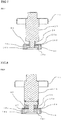
- FIG. 1 is a sectional view showing a vacuum interrupter according to Embodiment 1 of the present invention.
- FIG. 2 is a sectional view showing a contact portion of the vacuum interrupter according to Embodiment 1 of the present invention.
- FIG. 3 is a sectional view taken along the line III-III of FIG. 2 showing the vacuum interrupter according to Embodiment 1 of the present invention.
- FIG. 4 is a sectional view showing comparison of the moment to be exerted on the contact portion in the vacuum interrupter according to Embodiment 1 of the present invention.
- a reference numeral 10 denotes a vacuum vessel of the vacuum interrupter and, for example, the vacuum vessel is made of ceramics.
- 11 denotes a fixed side flange attached to the fixed side of the vacuum vessel 10;
- 12 denotes a movable side flange attached to the movable side of the vacuum vessel 10;
- 13 denotes a fixed side electrode rod which is supported to the fixed side flange 11 and is arranged in the vacuum vessel 10;
- 14 denotes a movable side electrode rod which can pass through the movable side flange 12, is arranged in the vacuum vessel 10, and is coaxially arranged with the fixed side electrode rod 13;
- 15 denotes an accordion shaped bellows made of thin metal which is coupled to the movable side electrode rod 14 and the movable side flange 12 and allows the movable side electrode rod 14 to be movable while the interior of the vacuum vessel 10 of the vacuum interrupter is kept vacuum.
- 16 denotes a fixed side contact which is attached to the tip of the fixed side electrode rod 13 and has a contact portion 16a; and although not shown in the drawing, 17 denotes a movable side contact to be connected to and disconnected from the fixed side contact 16, the movable side contact 17 being attached to the tip of the movable side electrode rod 14 and having a contact portion to be brought into contact with the contact portion 16a.
- a concave shaped spiral portion 16b is formed in a center portion on the contact portion 16a side of the fixed side contact 16 and arc shaped grooves 16c are formed from the spiral portion 16b toward the rim portion, what is called, a spiral shaped fixed side electrode is constituted.
- a concave shaped spiral portion 17b is formed in a center portion on the contact portion 17a of the movable side contact 17 and arc shaped grooves 17c are formed from the spiral portion 17b toward the rim portion, what is called, a spiral shaped movable side electrode is configured.
- the configuration is such that the thickness of a central portion of the reinforcement 19 is thickened, the step portion 19a of the reinforcement 19 is thinned than the thickness of the central portion, and the step portion 19a is arranged apart from the back 16d of the fixed side contact 16.
- 20 denotes a spacer arranged between the movable side electrode rod 14 and the movable side contact 17
- 21 denotes a reinforcement plate arranged between the spacer 20 and the movable side contact 17 and a configuration is such that a rim portion of the reinforcement plate 21 has a step portion 21a separated from the back 17d of the movable side contact 17. More specifically, the configuration is such that the thickness of a central portion of the reinforcement 21 is thickened, the step portion 21a of the reinforcement 21 is thinned than the thickness of the central portion, and the step portion 21a is arranged apart from the back 17d of the movable side contact 17.
- the shield 22 denotes a shield which is attached inside the vacuum vessel 10 and is arranged over the fixed side contact 16 and the movable side contact 17. Then, the shield 22 prevents metallic vapor, which is diffused from an arc that is ignited between the fixed side contact 16 and the movable side contact 17, from attaching to an inner wall of the vacuum vessel 10.
- the movable side contact 17 is contact closed by an operating mechanism of a circuit breaker (not shown in the drawing) and is pressurized by a contact pressure spring (not shown in the drawing); and when fault current is generated, the movable side contact 17 moves the movable side electrode rod 14 to a contact opened position by the operating mechanism to interrupt large current.
- the spiral shaped groove 16c is formed in the fixed side contact 16 and the spiral shaped groove 17c is formed in the movable side contact 17, the current flows along the shape of the spiral and thereby generating a magnetic field G, and the concentrated arc A is made to rotate and move without being remained at one place by the magnetic field G and arc driving force K by current I, whereby local overheat of the fixed side contact 16 and the movable side contact 17 is suppressed and interruption performance is improved.
- the step portion 19a with thin thickness in which the reinforcement plate 19 is separated from the back 16d of the rim portion of the fixed side contact 16 is provided and a diameter D3 of a portion in which the reinforcement 19 comes in contact with the fixed side contact 16 is set larger than an inner diameter D1 of a thick portion of the rim portion of the fixed side contact 16.
- the configuration is such that the thickness of the central portion of the reinforcement 19 is thickened, the step portion 19a of the reinforcement 19 is thinned than the thickness of the central portion, and the step portion 19a is arranged apart from the back 16d of the fixed side contact 16.
- material of the fixed side contact 16 is, for example, a composite material of copper and chromium and the reinforcement plate 19 is made of, for example, stainless steel.
- axial force F is applied to the thick portion of the rim portion of the fixed side contact 16 by contact pressure of the fixed side contact 16 or impact during contact closing; however, a support does not exist on the back of the thick portion and thus the axial force F is supported by the diameter D3 of the portion in which the reinforcement 21 comes in contact with the fixed side contact 16 on the back of the thin portion of the fixed side contact 16.
- the diameter D3 of the portion in which the reinforcement 19 comes in contact with the fixed side contact 16 is increased than the inner diameter D1 of the thick portion of the rim portion of the fixed side contact 16, whereby the backside of the thin portion of the fixed side contact 16 can be supported, the moment exerted on the thin portion of the fixed side contact 16 is extremely reduced, and the deformation and/or damage of the fixed side contact 16 can be prevented.
- the current I flows along the facing spiral shape and thereby generating the magnetic field G in a radial direction; and as shown in FIG. 3 , the arc driving force K is generated by the concentrated arc A and the magnetic field G and the concentrated arc A is driven along the circumference of the fixed side contact 16; however, the strength of the magnetic field G is strengthened in proportion to the current I that flows through this spiral shape and the arc driving force K also tends to increase.
- the reinforcement plate 5 comes in contact with the entire surface of the back of the contact 1 and the current is shunted to the reinforcement plate 5. Since the spiral shaped groove is not formed in the reinforcement plate 5, the current shunted to the reinforcement plate 5 does not flow through the spiral shape and thus the magnetic field cannot be generated. Furthermore, the current that flows through the spiral shape of the contact is also reduced by the amount of current that flows through the reinforcement plate 5; and accordingly, the magnetic field to be generated is reduced.
- the groove is not formed in the conventional reinforcement plate, a current flows.
- the current does not flow through a hatching portion of the step portion 19a of the reinforcement plate 19 shown in FIG. 3 ; and therefore, magnetic field strength of the fixed side contact 16 is improved by approximately 20 % than ever before and the interruption performance is improved by approximately 10 %.
- the fixed side contact 16 comes in contact with the reinforcement plate 19, the current is shunted to the reinforcement plate 19 and the current that flows along the spiral shape is reduced, and the magnetic field is reduced; however, the arc moves to the rim portion by electromagnetic force immediately after arc generation and begins to rotate on the rim portion; and therefore, the influence on the interruption performance is small. More particularly, as for the shape like JP 3 812 711 B2 in which the contact portion is positioned in the rim portion, the generation of the arc is limited to the contact portion of the rim portion and thus the influence to be exerted on the interruption performance by a magnetic field at a portion within the diameter D1 is imperceptible.
- the diameter D3 of the portion in which the reinforcement 19 comes in contact with the fixed side contact 16 needs to be smaller than the outer circumferential diameter D2 of the fixed side contact 16.
- a range of D1 ⁇ D3 ⁇ (D1 + D2)/2 has a profound effect and is effective for an improvement in magnetic field strength.
- a level difference is equal to or more than 0.5 mm.
- the metallic vapor generated between the fixed side contact 16 and the movable side contact 17 by the arc is dispersed in the axial direction through the groove 16c of the spiral shaped fixed side contact 16 and is dispersed to the inside or the like of the vacuum vessel 10 made of ceramics in the vacuum interrupter and the withstand voltage performance is degraded; however, the reinforcement plate 19 has the role of blocking the metallic vapor dispersed from the groove 16c of the fixed side contact 16 and preventing the degradation of the withstand voltage performance.
- the reinforcement plate 19 and the fixed side contact 16 are generally joined by a method such as blazing; however, if temperature in brazing is too high, brazing material between the reinforcement plate 19 and the fixed side contact 16 may creep up near the surface of the contact. However, if the brazing material is present adjacent to the surface of the contact, the brazing material is melted by the arc during the interruption of large current and the interruption performance may be degraded; and thus, control of blazing temperature becomes important.
- FIG. 5 is a sectional view showing a contact portion in a vacuum interrupter according to Embodiment 2 of the present invention.
- the shape of a reinforcement plate 23 is a shape in which a thin plate is bent. More specifically, a central portion of the thin plate-shaped reinforcement plate 23 is formed into a concave shaped portion by, for example, press working to serve as a portion that comes in contact with a fixed side contact 16, whereby a step portion 23a in which a rim portion of the reinforcement plate 23 is separated from the back 16d of the fixed side contact 16 can be configured, and it can be configured into a substantially equivalent shape to that of the aforementioned Embodiment 1.
- FIG. 6 is a sectional view showing a vacuum interrupter according to Embodiment 3 of the present invention.
- a spacer 18 formed with a step portion 18a in a rim portion thereof on the fixed side contact 16 side is arranged between a fixed side electrode rod 13 and a fixed side contact 16, and a fixed side reinforcement plate 24 is attached to the step portion 18a of the spacer 18, whereby a step portion 24a separated from the back 16d of the fixed side contact 16 can be configured in a rim portion of the fixed side reinforcement plate 24 and effects similar to those of the aforementioned respective embodiments can be exhibited.
- the spacer 18 and the fixed side reinforcement plate 24 are made as an integrated structure, the number of components can be further reduced and there can be obtained an effect that can be manufactured more inexpensively.
- FIG. 7 is a sectional view showing a contact portion in a vacuum interrupter according to Embodiment 4 of the present invention.
- the shape of a fixed side reinforcement plate 25 shown in FIG. 7 in this Embodiment 4 is a shape in which a stainless steel thin plate is bent, a rim portion of the fixed side reinforcement plate 25 constitutes a step portion 25a separated from the back 16d of a fixed side contact 16, and the fixed side reinforcement plate 25 is integrally structured with a spacer 26.
- the spacer 26 has the role of supporting the fixed side reinforcement plate 25, the fixed side reinforcement plate 25 is bent in an axial direction to have a positioning function by fitting to the diameter of a fixed side electrode rod 13.
- FIG. 8 is a sectional view showing a contact portion in a vacuum interrupter according to Embodiment 5 of the present invention.
- a configuration is such that a fixed side projection portion 27 is provided in a central portion on the back side of a fixed side contact 16, a central portion of a fixed side reinforcement plate 28 comes in contact with the fixed side projection portion 27 on the fixed side of the contact 16, and a rim portion of the fixed side reinforcement plate 28 has a step portion 28a to be arranged apart from the back 16d of the fixed side contact 16.
- the fixed side reinforcement plate 28 has a shape which is plate-shaped, is not provided with a level difference, and is flat washer-shaped.
- a level difference is formed by providing the fixed side projection portion 27 in the central portion on the back side of the fixed side contact 16, a portion in which the fixed side projection portion 27 comes in contact with the fixed side reinforcement plate 28 becomes a diameter D3, and effects regarding the improvement in interruption performance and the reinforcement of the fixed side contact 16 in the aforementioned Embodiment 1 can also be similarly obtained.
- the shape of the fixed side reinforcement plate 28 becomes simple and can be manufactured inexpensively by press working or the like.
- the level difference needs to be formed by providing the fixed side projection portion 27 in the central portion on the back side of the fixed side contact 16; however, since the fixed side contact 16 is generally manufactured by machining from the beginning, an increase in cost by the addition of the level difference is small and there is an advantage that can be manufactured inexpensively as a whole.
- a structure in which a spacer 18 is integrated with the fixed side reinforcement plate 28 in this FIG. 8 can also reduce the number of components and becomes an effective means and effects similar to those of the above-mentioned respective embodiments can be obtained.
- the fixed side contact 16 side are mainly described; however, although not shown in the drawings, the movable side contact 17 side can be similarly applied and the similar effects can be exhibited.
- the present invention can freely combine the respective embodiments and appropriately modify and/or omit the respective embodiments, within the scope of the present invention.
- the present invention is suitable for achieving a vacuum interrupter which can improve interruption performance of the vacuum interrupter while maintaining the strength of a contact portion.
Landscapes
- Engineering & Computer Science (AREA)
- Manufacturing & Machinery (AREA)
- High-Tension Arc-Extinguishing Switches Without Spraying Means (AREA)
Abstract
Description
- The present invention relates to a vacuum interrupter for use in, for example, a vacuum circuit breaker.
-
FIG. 9 is a sectional view in which a contact portion in a conventional vacuum interrupter is enlarged. Thiscontact 1 is arranged in a vacuum vessel and is formed with a plurality of spiral grooves, each of which smoothly changes its direction from a center portion to a rim portion. In this drawing, areinforcement plate 5 and aspacer 8 are arranged on the back of thecontact 1; and anelectrode rod 6 is joined to thecontact 1 via thereinforcement plate 5 and thespacer 8. - In such a spiral shaped
contact 1, when fault current is interrupted, current flows along thecontact 1 machined in the spiral shape and thereby generating a magnetic field in a radial direction, and a concentrated arc due to the fault current generated between thecontacts 1 is driven in a circumferential direction by the magnetic field, whereby the arc is prevented from remaining in a certain place of thecontact 1 and interruption performance is improved. - The
reinforcement plate 5 prevents metallic vapor or the like generated between thecontacts 1 during the interruption of fault current from dispersing to the backside of thecontact 1, from attaching to the inner surface of ceramics, and from degrading withstand voltage performance. - Furthermore, generally, a contact pressure is exerted between the
contacts 1 in a contact closed state; and force exceeding the contact pressure is further temporarily generated at a moment when thecontacts 1 collide during contact closing operation, a lot of stress is generated in thecontact 1, and thecontact 1 is likely to be deformed. Thereinforcement plate 5 also combines the role of reinforcing so that thecontact 1 does not deform by being arranged on the backside of thecontact 1 while coming in contact with thecontact 1. - Material such as stainless steel, which is stronger in strength and higher in resistance than the
contact 1, is generally used for material of thereinforcement plate 5; however, current is shunted to thereinforcement plate 5 according to the resistance ratio between theconta0ct 1 and thereinforcement plate 5. The spiral shaped groove is not formed in thereinforcement plate 5; and accordingly, a magnetic field is not generated from the current that flows through thereinforcement plate 5, the magnetic field generated from thecontact 1 is reduced by the amount of current that flows through thereinforcement plate 5 and it causes to degrade the interruption performance. - For example, if the structure is such that a contact does not come in contact with a reinforcement plate behind the contact as in U.S. Patent
US 8 039 771 B2 , current that flows through the reinforcement plate disappears and a magnetic field generated from the contact increases, but a function serving as the reinforcement of the contact also disappears and the contact is more likely to be deformed. - More particularly, in the case of a contact for use at a high contact pressure and a shape in which a recess at a central portion of the contact is large and which comes in contact at a rim portion as in Japanese Patent
JP 3 812 711 B2 -
- Patent Document 1:
US 8 039 771 B2 - Patent Document 2:
JP 3 812 711 B2 - In the aforementioned conventional vacuum interrupter, the reinforcement plate is arranged on the back of the contact and comes in contact with the entire surface of the contact in order to reinforce the contact; and accordingly, problems exist in that current during the interruption of fault current flows through not only the contact but also the reinforcement plate, the magnetic field due to the current that flows through the contact is reduced, and the interruption performance is degraded.
- The present invention has been made to solve the above described problem, and an object of the present invention is to improve interruption performance and a further object is to provide a vacuum interrupter which can also reinforce a contact.
- According to the present invention, there is provided a vacuum interrupter including: a fixed side contact and a movable side contact, each of which is arranged in a vacuum vessel to be able to connect and disconnect, has a contact portion to be connected to and disconnected from each other, and is formed with a plurality of arc shaped grooves from a center portion to a rim portion; a fixed side electrode rod connected to the fixed side contact; a movable side electrode rod connected to the movable side contact; a fixed side reinforcement plate which is arranged between the fixed side electrode rod and the fixed side contact, and whose rim portion has a step portion to be arranged apart from the back of the fixed side contact; and a movable side reinforcement plate which is arranged between the movable side electrode rod and the movable side contact, and whose rim portion has a step portion to be arranged apart from the back of the movable side contact.
- Furthermore, according to the present invention, there is provided a vacuum interrupter including: a fixed side contact and a movable side contact, each of which is arranged in a vacuum vessel to be able to connect and disconnect, has a contact portion to be connected to and disconnected from each other, and is formed with a plurality of arc shaped grooves from a center portion to a rim portion; a fixed side electrode rod connected to the fixed side contact; a movable side electrode rod connected to the movable side contact; a fixed side projection portion provided in a central portion on the back side of the fixed side contact; a movable side projection portion provided in a central portion on the back side of the movable side contact; a fixed side reinforcement plate which is arranged between the fixed side electrode rod and the fixed side contact, whose central portion comes in contact with the fixed side projection portion, and whose rim portion has a step portion to be arranged apart from the back of the fixed side contact; and a movable side reinforcement plate which is arranged between the movable side electrode rod and the movable side contact, whose central portion comes in contact with the movable side projection portion, and whose rim portion has a step portion to be arranged apart from the back of the movable side contact.
- According to the vacuum interrupter according to the present invention, the reinforcement plate which is arranged between the fixed side electrode rod and the fixed side contact, and whose rim portion has the step portion to be arranged apart from the back of the fixed side contact; and the reinforcement plate which is arranged between the movable side electrode rod and the movable side contact, and whose rim portion has the step portion to be arranged apart from the back of the movable side contact are provided, whereby, each step portion of the reinforcement plate does not come in contact with the fixed side contact and the movable side contact and therefore there can be obtained the vacuum interrupter that can improve interruption performance of the vacuum interrupter while maintaining the strength of a contact portion.
-
- FIG. 1
- is a sectional view showing a vacuum interrupter according to
Embodiment 1 of the present invention; - FIG. 2
- is a sectional view showing a contact portion of the vacuum interrupter according to
Embodiment 1 of the present invention; - FIG. 3
- is a sectional view taken along the line III-III of
FIG. 2 showing the vacuum interrupter according toEmbodiment 1 of the present invention; - FIG. 4
- is a sectional view showing a comparison of the moment to be exerted on the contact portion in the vacuum interrupter according to
Embodiment 1 of the present invention; - FIG. 5
- is a sectional view showing a contact portion in a vacuum interrupter according to
Embodiment 2 of the present invention; - FIG. 6
- is a sectional view showing a contact portion in a vacuum interrupter according to
Embodiment 3 of the present invention; - FIG. 7
- is a sectional view showing a contact portion in a vacuum interrupter according to
Embodiment 4 of the present invention; - FIG. 8
- is a sectional view showing a contact portion in a vacuum interrupter according to
Embodiment 5 of the present invention; and - FIG. 9
- is a sectional view showing a contact portion in a conventional vacuum interrupter.
- Hereinafter,
Embodiment 1 of the present invention will be described based onFIG. 1 to FIG. 4 . Then, in each of the drawings, identical or equivalent members and portions will be described with the same reference numerals (and letters) assigned thereto.FIG. 1 is a sectional view showing a vacuum interrupter according toEmbodiment 1 of the present invention.FIG. 2 is a sectional view showing a contact portion of the vacuum interrupter according toEmbodiment 1 of the present invention. -
FIG. 3 is a sectional view taken along the line III-III ofFIG. 2 showing the vacuum interrupter according toEmbodiment 1 of the present invention.FIG. 4 is a sectional view showing comparison of the moment to be exerted on the contact portion in the vacuum interrupter according toEmbodiment 1 of the present invention. - In these drawings, a
reference numeral 10 denotes a vacuum vessel of the vacuum interrupter and, for example, the vacuum vessel is made of ceramics. 11 denotes a fixed side flange attached to the fixed side of thevacuum vessel 10; 12 denotes a movable side flange attached to the movable side of thevacuum vessel 10; 13 denotes a fixed side electrode rod which is supported to the fixed side flange 11 and is arranged in thevacuum vessel 10; 14 denotes a movable side electrode rod which can pass through the movable side flange 12, is arranged in thevacuum vessel 10, and is coaxially arranged with the fixed side electrode rod 13; and 15 denotes an accordion shaped bellows made of thin metal which is coupled to the movableside electrode rod 14 and the movable side flange 12 and allows the movableside electrode rod 14 to be movable while the interior of thevacuum vessel 10 of the vacuum interrupter is kept vacuum. - 16 denotes a fixed side contact which is attached to the tip of the fixed side electrode rod 13 and has a contact portion 16a; and although not shown in the drawing, 17 denotes a movable side contact to be connected to and disconnected from the
fixed side contact 16, themovable side contact 17 being attached to the tip of the movableside electrode rod 14 and having a contact portion to be brought into contact with the contact portion 16a. - A concave shaped spiral portion 16b is formed in a center portion on the contact portion 16a side of the fixed
side contact 16 and arc shaped grooves 16c are formed from the spiral portion 16b toward the rim portion, what is called, a spiral shaped fixed side electrode is constituted. - Furthermore, also in the
movable side contact 17, similarly to the fixedside contact 16, a concave shaped spiral portion 17b is formed in a center portion on the contact portion 17a of themovable side contact 17 and arc shaped grooves 17c are formed from the spiral portion 17b toward the rim portion, what is called, a spiral shaped movable side electrode is configured. - 18 denotes a spacer arranged between the fixed side electrode rod 13 and the
fixed side contact 16; and 19 denotes a reinforcement plate arranged between the spacer 18 and thefixed side contact 16 and a configuration is such that a rim portion of thereinforcement plate 19 has a step portion 19a separated from the back 16d of thefixed side contact 16. - More specifically, the configuration is such that the thickness of a central portion of the
reinforcement 19 is thickened, the step portion 19a of thereinforcement 19 is thinned than the thickness of the central portion, and the step portion 19a is arranged apart from the back 16d of thefixed side contact 16. - 20 denotes a spacer arranged between the movable
side electrode rod 14 and themovable side contact 17; 21 denotes a reinforcement plate arranged between thespacer 20 and themovable side contact 17 and a configuration is such that a rim portion of thereinforcement plate 21 has a step portion 21a separated from the back 17d of themovable side contact 17. More specifically, the configuration is such that the thickness of a central portion of thereinforcement 21 is thickened, the step portion 21a of thereinforcement 21 is thinned than the thickness of the central portion, and the step portion 21a is arranged apart from the back 17d of themovable side contact 17. - Incidentally, 22 denotes a shield which is attached inside the
vacuum vessel 10 and is arranged over the fixedside contact 16 and themovable side contact 17. Then, the shield 22 prevents metallic vapor, which is diffused from an arc that is ignited between the fixedside contact 16 and themovable side contact 17, from attaching to an inner wall of thevacuum vessel 10. - During energization, the
movable side contact 17 is contact closed by an operating mechanism of a circuit breaker (not shown in the drawing) and is pressurized by a contact pressure spring (not shown in the drawing); and when fault current is generated, themovable side contact 17 moves the movableside electrode rod 14 to a contact opened position by the operating mechanism to interrupt large current. - After the fixed
side contact 16 has been separated from themovable side contact 17, an arc is generated between thefixed side contact 16 and themovable side contact 17; however, if the current exceeds approximately 10 kA, the arc is concentrated at one place and becomes a concentrated arc A. - At this time, the spiral shaped groove 16c is formed in the fixed
side contact 16 and the spiral shaped groove 17c is formed in themovable side contact 17, the current flows along the shape of the spiral and thereby generating a magnetic field G, and the concentrated arc A is made to rotate and move without being remained at one place by the magnetic field G and arc driving force K by current I, whereby local overheat of thefixed side contact 16 and themovable side contact 17 is suppressed and interruption performance is improved. - For example, although a description will be made on the fixed
side contact 16 side, as shown inFIG. 2 , the step portion 19a with thin thickness in which thereinforcement plate 19 is separated from the back 16d of the rim portion of the fixedside contact 16 is provided and a diameter D3 of a portion in which thereinforcement 19 comes in contact with the fixedside contact 16 is set larger than an inner diameter D1 of a thick portion of the rim portion of the fixedside contact 16. - More specifically, the configuration is such that the thickness of the central portion of the
reinforcement 19 is thickened, the step portion 19a of thereinforcement 19 is thinned than the thickness of the central portion, and the step portion 19a is arranged apart from the back 16d of the fixedside contact 16. Then, material of the fixedside contact 16 is, for example, a composite material of copper and chromium and thereinforcement plate 19 is made of, for example, stainless steel. - For example, as shown in
FIG. 4 , when a diameter D3 of a portion in which thereinforcement 21 comes in contact with the fixedside contact 16 is smaller than the inner diameter D1 of the thick portion of the rim portion of the fixedside contact 16, axial force F is applied to the thick portion of the rim portion of the fixedside contact 16 by contact pressure of the fixedside contact 16 or impact during contact closing; however, a support does not exist on the back of the thick portion and thus the axial force F is supported by the diameter D3 of the portion in which thereinforcement 21 comes in contact with the fixedside contact 16 on the back of the thin portion of the fixedside contact 16. - At this time, the moment M depending on the length of L=(D1-D3)/2 is generated on a contact thin portion L of the fixed
side contact 16 in a direction shown inFIG. 4 . A lot of stress is generated in the thin portion with low strength of the fixedside contact 16 by the moment M during the contact closing and possibility of generating deformation and/or damage of the fixedside contact 16 is increased by a large number of opening or closing operations. - However, in this
Embodiment 1, the diameter D3 of the portion in which thereinforcement 19 comes in contact with the fixedside contact 16 is increased than the inner diameter D1 of the thick portion of the rim portion of the fixedside contact 16, whereby the backside of the thin portion of the fixedside contact 16 can be supported, the moment exerted on the thin portion of the fixedside contact 16 is extremely reduced, and the deformation and/or damage of the fixedside contact 16 can be prevented. - Furthermore, in the spiral shaped contact, the current I flows along the facing spiral shape and thereby generating the magnetic field G in a radial direction; and as shown in
FIG. 3 , the arc driving force K is generated by the concentrated arc A and the magnetic field G and the concentrated arc A is driven along the circumference of the fixedside contact 16; however, the strength of the magnetic field G is strengthened in proportion to the current I that flows through this spiral shape and the arc driving force K also tends to increase. - In the conventional structure shown in
FIG. 9 , thereinforcement plate 5 comes in contact with the entire surface of the back of thecontact 1 and the current is shunted to thereinforcement plate 5. Since the spiral shaped groove is not formed in thereinforcement plate 5, the current shunted to thereinforcement plate 5 does not flow through the spiral shape and thus the magnetic field cannot be generated. Furthermore, the current that flows through the spiral shape of the contact is also reduced by the amount of current that flows through thereinforcement plate 5; and accordingly, the magnetic field to be generated is reduced. - In the vacuum interrupter according to this
Embodiment 1, as shown inFIG. 2 andFIG. 3 , since the step portion 19a of thereinforcement plate 19 does not come in contact with the fixedside contact 16 in an area on the outer diameter side than the diameter D3 of the portion in which thereinforcement 19 comes in contact with the fixedside contact 16, all the current flows through the fixedside contact 16. - Furthermore, since the groove is not formed in the conventional reinforcement plate, a current flows. However, the current does not flow through a hatching portion of the step portion 19a of the
reinforcement plate 19 shown inFIG. 3 ; and therefore, magnetic field strength of the fixedside contact 16 is improved by approximately 20 % than ever before and the interruption performance is improved by approximately 10 %. - As for an inner portion of the diameter D1 of the fixed
side contact 16, the fixedside contact 16 comes in contact with thereinforcement plate 19, the current is shunted to thereinforcement plate 19 and the current that flows along the spiral shape is reduced, and the magnetic field is reduced; however, the arc moves to the rim portion by electromagnetic force immediately after arc generation and begins to rotate on the rim portion; and therefore, the influence on the interruption performance is small. More particularly, as for the shape likeJP 3 812 711 B2 - If the diameter D3 of the portion in which the
reinforcement 19 comes in contact with the fixedside contact 16 is increased, an effect as the reinforcement of the fixedside contact 16 increases; however, the magnetic field tends to reduce by an increase in current that flows through thereinforcement plate 19 at the same time and, if the diameter D3 reaches an outer circumferential diameter D2 of the fixedside contact 16, the magnetic field strength becomes the same as that of the conventional structure. - Consequently, the diameter D3 of the portion in which the
reinforcement 19 comes in contact with the fixedside contact 16 needs to be smaller than the outer circumferential diameter D2 of the fixedside contact 16. Preferably, a range of D1 < D3 < (D1 + D2)/2 has a profound effect and is effective for an improvement in magnetic field strength. Furthermore, in order not to bring the fixedside contact 16 into contact with thereinforcement plate 19, it is preferable that a level difference is equal to or more than 0.5 mm. - When the large current is interrupted, the metallic vapor generated between the fixed
side contact 16 and themovable side contact 17 by the arc is dispersed in the axial direction through the groove 16c of the spiral shaped fixedside contact 16 and is dispersed to the inside or the like of thevacuum vessel 10 made of ceramics in the vacuum interrupter and the withstand voltage performance is degraded; however, thereinforcement plate 19 has the role of blocking the metallic vapor dispersed from the groove 16c of the fixedside contact 16 and preventing the degradation of the withstand voltage performance. - The larger the outer diameter D4 of the
reinforcement 19 is, the larger the interruption effect is; however, if the outer diameter D4 is larger than the outer circumferential diameter D2 of the fixedside contact 16, field strength at the tip of thereinforcement plate 19 is increased and the withstand voltage performance is degraded; and thus, it is desirable that the outer diameter D4 is smaller than the outer circumferential diameter D2 of the fixedside contact 16. - The
reinforcement plate 19 and the fixedside contact 16 are generally joined by a method such as blazing; however, if temperature in brazing is too high, brazing material between thereinforcement plate 19 and the fixedside contact 16 may creep up near the surface of the contact. However, if the brazing material is present adjacent to the surface of the contact, the brazing material is melted by the arc during the interruption of large current and the interruption performance may be degraded; and thus, control of blazing temperature becomes important. - In the shape of this
Embodiment 1, area in which the fixedside contact 16 is blazed to thereinforcement plate 19 is small in the back 16d of the fixedside contact 16, the amount of the brazing material can be reduced, the brazing material can be difficult to creep up adjacent to the surface of the contact even when the brazing temperature is high, the temperature control in brazing becomes easy, and an effect can also be obtained that the vacuum interrupter with higher reliability can be easily manufactured. - In the aforementioned
FIG. 2 andFIG. 3 , the description has been made on the fixed side electrode rod 13, the fixedside contact 16, and thereinforcement plate 19; however, although not shown in the drawings, the movableside electrode rod 14, themovable side contact 17, and thereinforcement plate 21 are also the same configuration and the same effects can be exhibited. -
Embodiment 2 of the present invention will be described with reference toFIG. 5. FIG. 5 is a sectional view showing a contact portion in a vacuum interrupter according toEmbodiment 2 of the present invention. - In a shape shown in
FIG. 5 inEmbodiment 2 of the present invention, the shape of a reinforcement plate 23 is a shape in which a thin plate is bent. More specifically, a central portion of the thin plate-shaped reinforcement plate 23 is formed into a concave shaped portion by, for example, press working to serve as a portion that comes in contact with a fixedside contact 16, whereby a step portion 23a in which a rim portion of the reinforcement plate 23 is separated from the back 16d of the fixedside contact 16 can be configured, and it can be configured into a substantially equivalent shape to that of theaforementioned Embodiment 1. - Also in the shape such as this, effects similar to those of the above-mentioned
Embodiments 1 can be obtained; and since the reinforcement plate 23 can be manufactured by the press working, there can be obtained an effect that can be manufactured more inexpensively. -
Embodiment 3 of the present invention will be described with reference toFIG. 6. FIG. 6 is a sectional view showing a vacuum interrupter according toEmbodiment 3 of the present invention. - In a shape shown in
FIG. 6 inEmbodiment 3 of the present invention, a spacer 18 formed with a step portion 18a in a rim portion thereof on the fixedside contact 16 side is arranged between a fixed side electrode rod 13 and a fixedside contact 16, and a fixedside reinforcement plate 24 is attached to the step portion 18a of the spacer 18, whereby a step portion 24a separated from the back 16d of the fixedside contact 16 can be configured in a rim portion of the fixedside reinforcement plate 24 and effects similar to those of the aforementioned respective embodiments can be exhibited. - Incidentally, if the spacer 18 and the fixed
side reinforcement plate 24 are made as an integrated structure, the number of components can be further reduced and there can be obtained an effect that can be manufactured more inexpensively. -
Embodiment 4 of the present invention will be described with reference toFIG. 7. FIG. 7 is a sectional view showing a contact portion in a vacuum interrupter according toEmbodiment 4 of the present invention. - The shape of a fixed
side reinforcement plate 25 shown inFIG. 7 in thisEmbodiment 4 is a shape in which a stainless steel thin plate is bent, a rim portion of the fixedside reinforcement plate 25 constitutes a step portion 25a separated from the back 16d of a fixedside contact 16, and the fixedside reinforcement plate 25 is integrally structured with aspacer 26. Although thespacer 26 has the role of supporting the fixedside reinforcement plate 25, the fixedside reinforcement plate 25 is bent in an axial direction to have a positioning function by fitting to the diameter of a fixed side electrode rod 13. - This allows the fixed
side reinforcement plate 25 to be manufactured by press working and a reduction in the number of components and a reduction in cost can be achieved at the same time. Furthermore, effects regarding the improvement in interruption performance and the reinforcement of the fixedside contact 16 in theaforementioned Embodiment 1 can also be similarly obtained. -
Embodiment 5 of the present invention will be described with reference toFIG. 8. FIG. 8 is a sectional view showing a contact portion in a vacuum interrupter according toEmbodiment 5 of the present invention. - In the shape of
FIG. 8 inEmbodiment 5 of the present invention, a configuration is such that a fixedside projection portion 27 is provided in a central portion on the back side of a fixedside contact 16, a central portion of a fixedside reinforcement plate 28 comes in contact with the fixedside projection portion 27 on the fixed side of thecontact 16, and a rim portion of the fixedside reinforcement plate 28 has a step portion 28a to be arranged apart from the back 16d of the fixedside contact 16. - The fixed
side reinforcement plate 28 has a shape which is plate-shaped, is not provided with a level difference, and is flat washer-shaped. In thisEmbodiment 5, a level difference is formed by providing the fixedside projection portion 27 in the central portion on the back side of the fixedside contact 16, a portion in which the fixedside projection portion 27 comes in contact with the fixedside reinforcement plate 28 becomes a diameter D3, and effects regarding the improvement in interruption performance and the reinforcement of the fixedside contact 16 in theaforementioned Embodiment 1 can also be similarly obtained. - According to
Embodiment 5 of the present invention, the shape of the fixedside reinforcement plate 28 becomes simple and can be manufactured inexpensively by press working or the like. The level difference needs to be formed by providing the fixedside projection portion 27 in the central portion on the back side of the fixedside contact 16; however, since the fixedside contact 16 is generally manufactured by machining from the beginning, an increase in cost by the addition of the level difference is small and there is an advantage that can be manufactured inexpensively as a whole. - Furthermore, a structure in which a spacer 18 is integrated with the fixed
side reinforcement plate 28 in thisFIG. 8 can also reduce the number of components and becomes an effective means and effects similar to those of the above-mentioned respective embodiments can be obtained. - In the
aforementioned Embodiment 2 toEmbodiment 5, the fixedside contact 16 side are mainly described; however, although not shown in the drawings, themovable side contact 17 side can be similarly applied and the similar effects can be exhibited. - Incidentally, the present invention can freely combine the respective embodiments and appropriately modify and/or omit the respective embodiments, within the scope of the present invention.
- The present invention is suitable for achieving a vacuum interrupter which can improve interruption performance of the vacuum interrupter while maintaining the strength of a contact portion.
-
- 10
- Vacuum vessel
- 13
- Fixed side electrode rod
- 14
- Movable side electrode rod
- 16
- Fixed side contact
- 16a
- Contact portion
- 16c
- Groove
- 16d
- Back
- 17
- Movable side contact
- 17a
- Contact portion
- 17c
- Groove
- 17d
- Back
- 18
- Spacer
- 19
- Fixed side reinforcement plate
- 19a
- Step portion
- 20
- Spacer
- 21
- Movable side reinforcement plate
- 21a
- Step portion
- 23
- Fixed side reinforcement plate
- 23a
- Step portion
- 24
- Fixed side reinforcement plate
- 24a
- Step portion
- 25
- Fixed side reinforcement plate
- 25a
- Step portion
- 26a
- Spacer
- 27
- Fixed side projection portion
- 28
- Fixed side reinforcement plate
- 28a
- Step portion
Claims (10)
- A vacuum interrupter comprising:- a fixed side contact and a movable side contact, each of which is arranged in a vacuum vessel to be able to connect and disconnect, has a contact portion to be connected to and disconnected from each other, and is formed with a plurality of arc shaped grooves from a center portion to a rim portion;- a fixed side electrode rod connected to the fixed side contact;- a movable side electrode rod connected to the movable side contact;- a fixed side reinforcement plate which is arranged between the fixed side electrode rod and the fixed side contact, and whose rim portion has a step portion to be arranged apart from the back of the fixed side contact; and- a movable side reinforcement plate which is arranged between the movable side electrode rod and the movable side contact, and whose rim portion has a step portion to be arranged apart from the back of the movable side contact.
- The vacuum interrupter according to claim 1,
wherein the step portion of the fixed side reinforcement plate is arranged apart from the back of the fixed side contact by thickening the thickness of a central portion of the fixed side reinforcement plate; and
the step portion of the movable side reinforcement plate is arranged apart from the back of the movable side contact by thickening the thickness of a central portion of the movable side reinforcement plate. - The vacuum interrupter according to claim 1,
wherein the step portion of the fixed side reinforcement plate is arranged apart from the back of the fixed side contact by forming a central portion of the fixed side reinforcement plate into a concave shaped portion to serve as a portion in which the fixed side reinforcement plate comes in contact with the fixed side contact; and
the step portion of the movable side reinforcement plate is arranged apart from the back of the movable side contact by forming a central portion of the movable side reinforcement plate into a concave shaped portion to serve as a portion in which the movable side reinforcement plate comes in contact with the movable side contact. - The vacuum interrupter according to claim 1,
wherein the step portion of the fixed side reinforcement plate is arranged apart from the back of the fixed side contact by arranging a spacer whose rim portion is formed with a step portion between the fixed side electrode rod and the fixed side contact, and by attaching the fixed side reinforcement plate on the step portion of the spacer; and
the step portion of the movable side reinforcement plate is arranged apart from the back of the movable side contact by arranging a spacer whose rim portion is formed with a step portion between the movable side electrode rod and the movable side contact, and by attaching the movable side reinforcement plate on the step portion of the spacer. - The vacuum interrupter according to claim 4,
wherein the fixed side reinforcement plate and the spacer are made as an integrated structure; and
wherein he movable side reinforcement plate and the spacer are made as an integrated structure. - The vacuum interrupter according to claim 1,
wherein when the diameter of the portion in which the fixed side reinforcement plate comes in contact with the fixed side contact and the diameter of the portion in which the movable side reinforcement plate comes in contact with the movable side contact are set to D3, the diameter of the fixed side contact and the diameter of the movable side contact are set to D2, and the inner diameter of a thick portion of the rim portion of the fixed side contact and the inner diameter of a thick portion of the rim portion of the movable side contact are set to D1, D1 is smaller than D3 and D3 is smaller than D2 (D1 < D3 < D2). - The vacuum interrupter according to any one of claims 1 to 6,
wherein a gap between the step portion of the fixed side reinforcement plate and the fixed side contact and a gap between the step portion of the movable side reinforcement plate and the movable side contact are equal to or more than 0.5 mm. - The vacuum interrupter according to any one of claims 1 to 7,
wherein the fixed side reinforcement plate and the movable side reinforcement plate are made of stainless steel material. - The vacuum interrupter according to any one of claims 1 to 8,
wherein the fixed side contact and the movable side contact are made of Cu-Cr based material containing from 20 to 60 wt-% Cr. - A vacuum interrupter comprising:- a fixed side contact and a movable side contact, each of which is arranged in a vacuum vessel to be able to connect and disconnect, has a contact portion to be connected to and disconnected from each other, and is formed with a plurality of arc shaped grooves from a center portion to a rim portion;- a fixed side electrode rod connected to the fixed side contact;- a movable side electrode rod connected to the movable side contact;- a fixed side projection portion provided in a central portion on the back side of the fixed side contact;- a movable side projection portion provided in a central portion on the back side of the movable side contact;- a fixed side reinforcement plate which is arranged between the fixed side electrode rod and the fixed side contact, whose central portion comes in contact with the fixed side projection portion, and whose rim portion has a step portion to be arranged apart from the back of the fixed side contact; and- a movable side reinforcement plate which is arranged between the movable side electrode rod and the movable side contact, whose central portion comes in contact with the movable side projection portion, and whose rim portion has a step portion to be arranged apart from the back of the movable side contact.
Applications Claiming Priority (2)
| Application Number | Priority Date | Filing Date | Title |
|---|---|---|---|
| JP2016083334 | 2016-04-19 | ||
| PCT/JP2017/008423 WO2017183323A1 (en) | 2016-04-19 | 2017-03-03 | Vacuum valve |
Publications (3)
| Publication Number | Publication Date |
|---|---|
| EP3447783A1 true EP3447783A1 (en) | 2019-02-27 |
| EP3447783A4 EP3447783A4 (en) | 2019-03-13 |
| EP3447783B1 EP3447783B1 (en) | 2026-01-07 |
Family
ID=60116031
Family Applications (1)
| Application Number | Title | Priority Date | Filing Date |
|---|---|---|---|
| EP17785666.3A Active EP3447783B1 (en) | 2016-04-19 | 2017-03-03 | Vacuum interrupter |
Country Status (5)
| Country | Link |
|---|---|
| US (1) | US10650995B2 (en) |
| EP (1) | EP3447783B1 (en) |
| JP (1) | JP6342090B2 (en) |
| CN (1) | CN209298004U (en) |
| WO (1) | WO2017183323A1 (en) |
Families Citing this family (3)
| Publication number | Priority date | Publication date | Assignee | Title |
|---|---|---|---|---|
| CN113678219B (en) * | 2019-04-23 | 2024-09-27 | 三菱电机株式会社 | Vacuum valve |
| JP7664922B2 (en) * | 2020-05-28 | 2025-04-18 | 三菱電機株式会社 | Vacuum valve |
| CN112509856B (en) * | 2020-09-25 | 2022-10-21 | 平高集团有限公司 | Contact coil for generating arc extinguishing magnetic field and vacuum arc extinguishing chamber contact structure |
Family Cites Families (18)
| Publication number | Priority date | Publication date | Assignee | Title |
|---|---|---|---|---|
| US3244843A (en) * | 1963-10-16 | 1966-04-05 | Jennings Radio Mfg Corp | Arc-controlling auxiliary contact assembly for electric switches |
| GB1163271A (en) * | 1965-08-06 | 1969-09-04 | English Electric Co Ltd | Circuit Interrupters |
| DE2124426A1 (en) * | 1971-05-17 | 1972-11-23 | Siemens AG, 1000 Berlin u. 8000 München | Vacuum switch contact |
| JPS5086678U (en) * | 1973-12-14 | 1975-07-23 | ||
| JPS52150571A (en) * | 1976-06-09 | 1977-12-14 | Hitachi Ltd | Vacuum breaker electrode |
| US4588879A (en) * | 1982-11-30 | 1986-05-13 | Kabushika Kaisha Meidensha | Vacuum interrupter |
| KR910005759B1 (en) * | 1987-03-24 | 1991-08-02 | 미쓰비시덴기 가부시기가이샤 | Vacuum switch |
| DE4119191C2 (en) * | 1991-06-11 | 1997-07-03 | Abb Patent Gmbh | Contact arrangement for a vacuum interrupter |
| JP3812711B2 (en) | 1999-06-04 | 2006-08-23 | 三菱電機株式会社 | Vacuum valve |
| DE10027198B4 (en) | 1999-06-04 | 2006-06-22 | Mitsubishi Denki K.K. | Electrode for a paired arrangement in a vacuum tube of a vacuum switch |
| KR100386845B1 (en) * | 2000-10-16 | 2003-06-09 | 엘지산전 주식회사 | Electrode structure for vacuum interrupter using aial magnetic field |
| JP4979604B2 (en) | 2008-01-21 | 2012-07-18 | 株式会社日立製作所 | Electrical contacts for vacuum valves |
| US8039771B2 (en) | 2008-08-11 | 2011-10-18 | Eaton Corporation | Vacuum envelope including self-aligning end shield, vacuum interrupter, vacuum circuit interrupter and method including the same |
| KR101362622B1 (en) * | 2010-02-24 | 2014-02-12 | 미쓰비시덴키 가부시키가이샤 | Vacuum valve |
| KR101115639B1 (en) * | 2010-10-18 | 2012-02-15 | 엘에스산전 주식회사 | Contact assembly of the vacuum interrupter |
| KR101415065B1 (en) * | 2010-11-17 | 2014-07-04 | 엘에스산전 주식회사 | Contact apparatus for circuit breaker |
| US20140048514A1 (en) * | 2012-08-20 | 2014-02-20 | Ganesh K. Balasubramanian | Contact assembly and vacuum switch including the same |
| JP2014127280A (en) * | 2012-12-25 | 2014-07-07 | Toshiba Corp | Vacuum valve |
-
2017
- 2017-03-03 JP JP2017558751A patent/JP6342090B2/en active Active
- 2017-03-03 US US16/072,766 patent/US10650995B2/en active Active
- 2017-03-03 EP EP17785666.3A patent/EP3447783B1/en active Active
- 2017-03-03 CN CN201790000644.8U patent/CN209298004U/en active Active
- 2017-03-03 WO PCT/JP2017/008423 patent/WO2017183323A1/en not_active Ceased
Also Published As
| Publication number | Publication date |
|---|---|
| EP3447783A4 (en) | 2019-03-13 |
| US20190035578A1 (en) | 2019-01-31 |
| EP3447783B1 (en) | 2026-01-07 |
| US10650995B2 (en) | 2020-05-12 |
| JP6342090B2 (en) | 2018-06-13 |
| WO2017183323A1 (en) | 2017-10-26 |
| CN209298004U (en) | 2019-08-23 |
| JPWO2017183323A1 (en) | 2018-04-26 |
Similar Documents
| Publication | Publication Date | Title |
|---|---|---|
| US10650995B2 (en) | Vacuum interrupter | |
| EP2485235B1 (en) | Vacuum interrupter for vacuum circuit breaker | |
| EP3089188B1 (en) | Opening and closing device | |
| EP3378084B1 (en) | Maximizing wall thickness of a cu-cr floating center shield component by moving contact gap away from center flange axial location | |
| KR101362622B1 (en) | Vacuum valve | |
| CN113678219A (en) | vacuum valve | |
| JP4818530B2 (en) | Vacuum valve | |
| KR102102028B1 (en) | Clearance-control-type seal structure | |
| EP2920801B1 (en) | Contact system | |
| EP2797095B1 (en) | Tulip contact for circuit breaker | |
| EP2469562A1 (en) | Interrupter insert for a circuit breaker arrangement | |
| JP5389058B2 (en) | Vacuum valve | |
| EP3588528B1 (en) | Gas-insulated high or medium voltage circuit breaker with ring-like element | |
| JP4703360B2 (en) | Vacuum valve | |
| CN219917007U (en) | Vacuum arc-extinguishing chamber assembly without installing protective cover | |
| JP2014127280A (en) | Vacuum valve | |
| EP3796353A1 (en) | Contact arrangement | |
| JP6846878B2 (en) | Vacuum valve | |
| EP1926116A1 (en) | Puffer circuit breaker with reduced puffer volume pressure | |
| JP2006019077A (en) | Vacuum valve | |
| JP2015156274A (en) | Vacuum valve or switch with vacuum valve | |
| JP2008091267A (en) | Vacuum valve | |
| JP2013041735A (en) | Vacuum circuit breaker electrode | |
| JP2006079862A (en) | Vacuum valve |
Legal Events
| Date | Code | Title | Description |
|---|---|---|---|
| STAA | Information on the status of an ep patent application or granted ep patent |
Free format text: STATUS: THE INTERNATIONAL PUBLICATION HAS BEEN MADE |
|
| PUAI | Public reference made under article 153(3) epc to a published international application that has entered the european phase |
Free format text: ORIGINAL CODE: 0009012 |
|
| STAA | Information on the status of an ep patent application or granted ep patent |
Free format text: STATUS: REQUEST FOR EXAMINATION WAS MADE |
|
| 17P | Request for examination filed |
Effective date: 20181011 |
|
| AK | Designated contracting states |
Kind code of ref document: A1 Designated state(s): AL AT BE BG CH CY CZ DE DK EE ES FI FR GB GR HR HU IE IS IT LI LT LU LV MC MK MT NL NO PL PT RO RS SE SI SK SM TR |
|
| AX | Request for extension of the european patent |
Extension state: BA ME |
|
| A4 | Supplementary search report drawn up and despatched |
Effective date: 20190213 |
|
| RIC1 | Information provided on ipc code assigned before grant |
Ipc: H01H 33/664 20060101AFI20190207BHEP |
|
| DAV | Request for validation of the european patent (deleted) | ||
| DAX | Request for extension of the european patent (deleted) | ||
| STAA | Information on the status of an ep patent application or granted ep patent |
Free format text: STATUS: EXAMINATION IS IN PROGRESS |
|
| 17Q | First examination report despatched |
Effective date: 20211015 |
|
| GRAP | Despatch of communication of intention to grant a patent |
Free format text: ORIGINAL CODE: EPIDOSNIGR1 |
|
| STAA | Information on the status of an ep patent application or granted ep patent |
Free format text: STATUS: GRANT OF PATENT IS INTENDED |
|
| INTG | Intention to grant announced |
Effective date: 20250820 |
|
| GRAS | Grant fee paid |
Free format text: ORIGINAL CODE: EPIDOSNIGR3 |
|
| GRAA | (expected) grant |
Free format text: ORIGINAL CODE: 0009210 |
|
| STAA | Information on the status of an ep patent application or granted ep patent |
Free format text: STATUS: THE PATENT HAS BEEN GRANTED |
|
| AK | Designated contracting states |
Kind code of ref document: B1 Designated state(s): AL AT BE BG CH CY CZ DE DK EE ES FI FR GB GR HR HU IE IS IT LI LT LU LV MC MK MT NL NO PL PT RO RS SE SI SK SM TR |
|
| REG | Reference to a national code |
Ref country code: CH Ref legal event code: F10 Free format text: ST27 STATUS EVENT CODE: U-0-0-F10-F00 (AS PROVIDED BY THE NATIONAL OFFICE) Effective date: 20260107 Ref country code: GB Ref legal event code: FG4D |
|
| REG | Reference to a national code |
Ref country code: DE Ref legal event code: R096 Ref document number: 602017093458 Country of ref document: DE |
|
| REG | Reference to a national code |
Ref country code: IE Ref legal event code: FG4D |
|
| PGFP | Annual fee paid to national office [announced via postgrant information from national office to epo] |
Ref country code: DE Payment date: 20260218 Year of fee payment: 10 |