EP3447755A1 - Lighting system - Google Patents
Lighting system Download PDFInfo
- Publication number
- EP3447755A1 EP3447755A1 EP18187794.5A EP18187794A EP3447755A1 EP 3447755 A1 EP3447755 A1 EP 3447755A1 EP 18187794 A EP18187794 A EP 18187794A EP 3447755 A1 EP3447755 A1 EP 3447755A1
- Authority
- EP
- European Patent Office
- Prior art keywords
- section
- abutment element
- positioning
- lighting modules
- backstop
- Prior art date
- Legal status (The legal status is an assumption and is not a legal conclusion. Google has not performed a legal analysis and makes no representation as to the accuracy of the status listed.)
- Withdrawn
Links
- 239000000725 suspension Substances 0.000 claims abstract description 37
- 230000007704 transition Effects 0.000 claims description 6
- 239000004020 conductor Substances 0.000 description 6
- 238000000034 method Methods 0.000 description 3
- 230000008878 coupling Effects 0.000 description 2
- 238000010168 coupling process Methods 0.000 description 2
- 238000005859 coupling reaction Methods 0.000 description 2
- 150000003071 polychlorinated biphenyls Chemical class 0.000 description 2
- 238000004026 adhesive bonding Methods 0.000 description 1
- 238000000429 assembly Methods 0.000 description 1
- 230000000712 assembly Effects 0.000 description 1
- 238000006073 displacement reaction Methods 0.000 description 1
- 238000009434 installation Methods 0.000 description 1
- 238000012423 maintenance Methods 0.000 description 1
- 239000000463 material Substances 0.000 description 1
- 238000012986 modification Methods 0.000 description 1
- 230000004048 modification Effects 0.000 description 1
- 238000003466 welding Methods 0.000 description 1
Images



Classifications
-
- G—PHYSICS
- G09—EDUCATION; CRYPTOGRAPHY; DISPLAY; ADVERTISING; SEALS
- G09F—DISPLAYING; ADVERTISING; SIGNS; LABELS OR NAME-PLATES; SEALS
- G09F13/00—Illuminated signs; Luminous advertising
- G09F13/04—Signs, boards or panels, illuminated from behind the insignia
-
- F—MECHANICAL ENGINEERING; LIGHTING; HEATING; WEAPONS; BLASTING
- F21—LIGHTING
- F21S—NON-PORTABLE LIGHTING DEVICES; SYSTEMS THEREOF; VEHICLE LIGHTING DEVICES SPECIALLY ADAPTED FOR VEHICLE EXTERIORS
- F21S8/00—Lighting devices intended for fixed installation
-
- F—MECHANICAL ENGINEERING; LIGHTING; HEATING; WEAPONS; BLASTING
- F21—LIGHTING
- F21V—FUNCTIONAL FEATURES OR DETAILS OF LIGHTING DEVICES OR SYSTEMS THEREOF; STRUCTURAL COMBINATIONS OF LIGHTING DEVICES WITH OTHER ARTICLES, NOT OTHERWISE PROVIDED FOR
- F21V21/00—Supporting, suspending, or attaching arrangements for lighting devices; Hand grips
- F21V21/14—Adjustable mountings
-
- G—PHYSICS
- G09—EDUCATION; CRYPTOGRAPHY; DISPLAY; ADVERTISING; SEALS
- G09F—DISPLAYING; ADVERTISING; SIGNS; LABELS OR NAME-PLATES; SEALS
- G09F13/00—Illuminated signs; Luminous advertising
- G09F13/20—Illuminated signs; Luminous advertising with luminescent surfaces or parts
- G09F13/22—Illuminated signs; Luminous advertising with luminescent surfaces or parts electroluminescent
-
- F—MECHANICAL ENGINEERING; LIGHTING; HEATING; WEAPONS; BLASTING
- F21—LIGHTING
- F21Y—INDEXING SCHEME ASSOCIATED WITH SUBCLASSES F21K, F21L, F21S and F21V, RELATING TO THE FORM OR THE KIND OF THE LIGHT SOURCES OR OF THE COLOUR OF THE LIGHT EMITTED
- F21Y2103/00—Elongate light sources, e.g. fluorescent tubes
- F21Y2103/10—Elongate light sources, e.g. fluorescent tubes comprising a linear array of point-like light-generating elements
-
- F—MECHANICAL ENGINEERING; LIGHTING; HEATING; WEAPONS; BLASTING
- F21—LIGHTING
- F21Y—INDEXING SCHEME ASSOCIATED WITH SUBCLASSES F21K, F21L, F21S and F21V, RELATING TO THE FORM OR THE KIND OF THE LIGHT SOURCES OR OF THE COLOUR OF THE LIGHT EMITTED
- F21Y2115/00—Light-generating elements of semiconductor light sources
- F21Y2115/10—Light-emitting diodes [LED]
-
- G—PHYSICS
- G09—EDUCATION; CRYPTOGRAPHY; DISPLAY; ADVERTISING; SEALS
- G09F—DISPLAYING; ADVERTISING; SIGNS; LABELS OR NAME-PLATES; SEALS
- G09F13/00—Illuminated signs; Luminous advertising
- G09F13/20—Illuminated signs; Luminous advertising with luminescent surfaces or parts
- G09F13/22—Illuminated signs; Luminous advertising with luminescent surfaces or parts electroluminescent
- G09F2013/222—Illuminated signs; Luminous advertising with luminescent surfaces or parts electroluminescent with LEDs
Definitions
- Embodiments of the present disclosure relate to lighting system and, more particularly, to suspension assembly of the lighting system.
- Installers are always looking for a quicker and reliable means to install LED lighting modules into a box sign.
- bars and rails have been used to support the LED lighting modules.
- prepopulated strings of LED lighting modules have been hung in the box sign from top and bottom supports to hold the string of LED lighting modules. In this way, many different strings need to be made depending on the depth of the sign.
- clamp or tie used to hold the string of modules causes uneven and non-repeatable spacing among LED lighting modules, and the clamps come undone or the ties become loose as well.
- a lighting system comprising at least two lighting modules, each lighting modules having a plurality of light emitting elements which are electrically coupled to one another; and a suspension assembly, configured for longitudinally attaching to the at least two lighting modules to be arranged as two lighting modules adjacent to each other.
- the suspension assembly includes a first section configured for attaching to one of the two adjacent lighting modules; and a second section configured for attaching to the other one of the two adjacent lighting modules; wherein the first section and the second section are mechanically connected for adjusting the longitudinal distance between the two adjacent lighting modules.
- a lighting system comprising at least two lighting modules, each lighting modules having a plurality of light emitting elements which are electrically coupled to one another; and a suspension assembly, configured for longitudinally attaching to the at least two lighting modules to be arranged as two lighting modules adjacent to each other.
- the suspension assembly comprising: a first section configured for attaching to both of the two adjacent lighting modules; and a second section configured for fastening with both of the two adjacent lighting modules; wherein the first section and the second section are mechanically connected for adjusting the longitudinal distance between the two adjacent lighting modules.
- embodiments of the disclosure provide a lighting system. It may be a separate component in various application, including cabinet signs, doubled-sided box signs, and other like applications built for use with lighting fixtures.
- the suspension assembly involved in the lighting system is simply to adjust for multiple depths after installation, easy connection for uniformity spacing among lighting modules, and simple maintenance.
- FIGS. 1 and 2 depict an exemplary embodiment of a lighting system 1 with a suspension assembly 20 in different operation states.
- the lighting system 1 further includes at least two lighting modules 10, the suspension assembly 20 is longitudinally attached to each two adjacent lighting modules 10 from top to bottom.
- the suspension assembly 20 connects with two adjacent lighting modules 10 at both lateral ends of the adjacent lighting modules 10, so as to keep the lighting modules 10 as connected be relatively stable, and to easily balance a longitudinal distance D between the two adjacent lighting modules 10, i.e., evenly spaced from one another in a direction parallel to a longitudinal axis C.
- the suspension assembly 20 in the exemplary lighting system illustrated herein is fixed, such as by gluing or welding, to each two adjacent lighting modules 10.
- the suspension assembly 20 may be integrally formed with the lighting modules 10.
- Each lighting modules 10 generally includes a plurality of light emitting elements 11, such as light emitting diodes (LEDs), which are electrically coupled to one another and are mounted on a printed circuit board (PCB) 12.
- the lighting system 1 also includes at least one flexible electrical conductor 30 which is electrically and mechanically connected to the lighting modules 10 for supplying power to the LEDs mounted on the PCBs 12.
- the flexible electrical conductor 30 may be pulled (shown in Fig. 1 ) or loosen (shown in Fig. 2 ).
- the suspension assembly 20 in this exemplary embodiment as illustrated includes a first section 21 and a second section 22, which are mechanically connected.
- the first section 21 is attached to one of the two adjacent lighting modules 10 and the corresponding second section 22 is attached to the other one.
- the first section 21 in this exemplary embodiment as illustrated includes a plurality of backstop elements 211 along the length of the first section 21.
- Each backstop element 211, projecting from an outer surface 2103 of the first section 21, includes a sliding surface 2111 with a smaller slope relative to the outer surface 2103 and a backstop surface 2112 with a larger slope, even perpendicular to the outer surface 2103 of the first section 21.
- the second section 22 in this exemplary embodiment as illustrated includes a positioning portion 2201 configured for corresponding to the backstop elements 211 so as to put the first section 21 at a desirable position.
- the second section 22 further includes a sliding portion 2202 configured for the first section 21 to slide thereon along the length of the second section 22.
- the positioning portion 2201 includes a positioning channel 222 configured for the first section 21 to get in and out thereof, an abutment element 221 configured for corresponding to the backstop elements 211, an elastic control element 223 for controlling the abutment element 221.
- the elastic control element 223 includes a control button 2231 for being pressed, and a driving arm 2232 connecting with the abutment element 221 and the control button 2231. When the control button 2233 is pressed, the abutment element 221 will be in response to the control button 2231 through the driving arm 2232.
- the first section 21 gets through the positioning channel 222 and moves ahead by sliding onto the sliding portion 2202.
- the abutment element 221 contacts with the backstop element 211, i.e., the abutment element 221 slides across the sliding surface 2111, then slides back to abut the backstop surface 2112 if needed, so as to fix the first section 21 at a desirable position.
- the control button 2231 of the elastic control element 223 is pressed so that abutment element 221 is driven to not abut the backstop element 211, i.e., is controlled to release from the backstop elements 211 which fixes the first section 21 in previous positon.
- the abutment element 221 is controlled to be ready to correspond to the backstop elements 211 when the first section 21 gets in the positioning channel 222 and the elastic control element 223 is not pressed; and the abutment element 221 is controlled to release from the backstop elements 211 when the elastic control element 223 is pressed.
- the first section 21 further includes a plurality of flanges 2102 which position at edges of the first section 21 and extend against the outer surface 2103 of the first section 21. During sliding, the flanges 2102 contacts with the sliding portion 2202 of the second section 22 and provides frictional force so as to prevent from skidding.
- FIGS. 8 and 9 illustrate another example of a lighting system 1' with a suspension assembly 20' in different operation states.
- the lighting system 1' also includes at least two lighting modules 10, the suspension assembly 20' is longitudinally attached to each two adjacent lighting modules 10 from top to bottom, and is configured to keep the lighting modules 10 as connected be relatively stable as well as to easily balance a longitudinal distance D between the two adjacent lighting modules 10, i.e., evenly spaced from one another in a direction parallel to a longitudinal axis C.
- the lighting system 1' also includes at least one flexible electrical conductor 30 which is electrically and mechanically connected to the lighting modules 10 for supplying power to the LEDs 11 mounted on the PCBs. When the suspension assembly 20' adjust the longitudinal distance D between two adjacent lighting modules 10, the flexible electrical conductor 30 may be pulled (shown in Fig. 8 ) or loosen (shown in Fig. 9 ).
- the suspension assembly 20' in this exemplary embodiment as illustrated includes a first section 21' and a second section 22', which are mechanically connected.
- the first section 21' is attached to one of the two adjacent lighting modules 10 and the corresponding second first section 22' is attached to the other one.
- the first section 21' in this exemplary embodiment as illustrated includes a plurality of positioning portions 2101' along the length of the first section 21'.
- Each positioning portions 2101' integrally formed by one through-hole on an outer surface 2102' of the first section 21', includes a backstop element 211' with a first inner width w1, an elastic transition region 213' with a second inner width w2 and a positioning element 212' with a third inner width w3.
- the first inner width w1 is smaller than the third inner width w3 and the first inner width w1 is not smaller than the second inner width w2.
- the second inner width w2 is smaller than the first inner width w1.
- the second section 22' in this exemplary embodiment as illustrated includes a plurality of protrusion portions 2201' along the length of the second section 22'.
- Each protrusion portions 2201' integrally projecting from an outer surface 2202' of the second section 22', includes a first abutment element 221' with a first outer width w1' and a second abutment element 222'. with a second outer width w2'.
- the first outer width w1' is smaller than the second outer width w2'.
- the first outer width w1' is not smaller than the second inner width w2, the first outer width w1' is smaller than the first inner width w1, the third inner width w3 is smaller than the second outer width w2'.
- the positioning element 212' is configured for the protrusion portions 2201' to get in and out thereof
- the backstop element 211' is configured for corresponding to both of the first abutment element 221' and the second abutment element 222'.
- the protrusion portions 2201' get in the positioning element 212', i.e., the second abutment element 222' gets through the positioning element 212' where the first abutment element 221' follows
- the first abutment element 221' will get through the elastic transition region 213' to the backstop element 211' under the force of pulling from top to bottom along the y direction.
- the second abutment element 222' and the outer surface 2202'of the second section 22' defines the displacement that the first abutment element 221' may take place along the z direction so that the protrusion portions 2201' may be fixed in the backstop element 211', then both of the first section 21' and the second section 22' can be defined in a desirable position.
- the first abutment element 221' will get through the elastic transition region 213' to the positioning element 212' under the force of pulling from bottom to top along the y direction, then get out from the positioning portion 2101'. Accordingly, the protrusion portions 2201' of the second section 22' that was fixed in specific positioning portions 2101' of the first section 21' can be released from the previous position and can be re-positioned by selecting other desirable positioning portions 2101' of the first section 21'.
- FIGS. 14 and 15 illustrate another example of a lighting system 1" with a suspension assembly 20" in different operation states.
- the lighting system 1" also includes at least two lighting modules 10", the suspension assembly 20" is longitudinally attached to each two adjacent lighting modules 10" from top to bottom, and is configured to keep the lighting modules 10" as connected be relatively stable as well as to easily balance a longitudinal distance D between the two adjacent lighting modules 10", i.e., evenly spaced from one another in a direction parallel to a longitudinal axis C.
- the lighting system 1" also includes at least one flexible electrical conductor 30 which is electrically and mechanically connected to the lighting modules 10" for supplying power to the LEDs 11 mounted on the lighting modules 10". When the suspension assembly 20" adjust the longitudinal distance D between two adjacent lighting modules 10", the flexible electrical conductor 30 may be pulled (shown in Fig. 14 ) or loosen (shown in Fig. 15 ).
- the suspension assembly 20" in this exemplary embodiment as illustrated includes a first section 21" and a second section 22", which are mechanically connected.
- the first section 21" is attached to both of the two adjacent lighting modules 10" and the corresponding second first section 22" is fastened with both of the two adjacent lighting modules 10".
- the first section 21" in this exemplary embodiment as illustrated includes a plurality of positioning portions 2101" along the length of the first section 21".
- Each positioning portions 2101", integrally formed by one through-hole on an outer surface 2102" of the first section 21" includes a backstop element 211" with a first inner width w1", an elastic transition region 213" with a second inner width w2" and a positioning element 212" with a third inner width w3".
- the first inner width w1" is smaller than the third inner width w3" and the first inner width w1" is not smaller than the second inner width w2".
- the second inner width w2" is smaller than the first inner width w1".
- the second section 22" in this exemplary embodiment as illustrated includes a plurality of protrusion portions 2201" along the width of the lighting modules 10".
- Each protrusion portions 2201 integrally projecting from an outer surface 101" of the lighting modules 10
- the first outer width w1"' is smaller than the second outer width w2"'.
- the first outer width w1"' is not smaller than the second inner width w2
- the first outer width w1"' is smaller than the first inner width w1
- the third inner width w3" is smaller than the second outer width w2"'.
- the positioning element 212" is configured for the protrusion portions 2201" to get in and out thereof
- the backstop element 211" is configured for corresponding to both of the first abutment element 221" and the second abutment element 222'
- the specific operation manner of these elements is as same as the embodiment shown in FIGS. 10 to 13 as described above.
Landscapes
- Engineering & Computer Science (AREA)
- Physics & Mathematics (AREA)
- General Physics & Mathematics (AREA)
- Theoretical Computer Science (AREA)
- General Engineering & Computer Science (AREA)
- Fastening Of Light Sources Or Lamp Holders (AREA)
- Non-Portable Lighting Devices Or Systems Thereof (AREA)
Abstract
The present disclosure is directed to a lighting system (1), the lighting system (1) comprising at least two lighting modules. Each lighting modules includes a plurality of light emitting elements which are electrically coupled to one another. The lighting system (1) further comprises a suspension assembly which is configured for longitudinally attaching to the at least two lighting modules to be arranged as two lighting modules adjacent to each other. The suspension assembly includes a first section configured for attaching to one of the two adjacent lighting modules, and a second section configured for attaching to the other one of the two adjacent lighting modules. The first section and the second section are mechanically connected for adjusting the longitudinal distance between the two adjacent lighting modules.
Description
- Embodiments of the present disclosure relate to lighting system and, more particularly, to suspension assembly of the lighting system.
- Installers are always looking for a quicker and reliable means to install LED lighting modules into a box sign. Typically, bars and rails have been used to support the LED lighting modules. In the recent past prepopulated strings of LED lighting modules have been hung in the box sign from top and bottom supports to hold the string of LED lighting modules. In this way, many different strings need to be made depending on the depth of the sign. Moreover, clamp or tie used to hold the string of modules causes uneven and non-repeatable spacing among LED lighting modules, and the clamps come undone or the ties become loose as well.
- Accordingly, it would be desirable to provide a better configuration to support the LED lighting modules at multiple depths and to be easily set for the spacing as needed among LED lighting modules, mounted from top to bottom.
- In accordance with one embodiment disclosed herein, a lighting system is provided. The lighting system comprises at least two lighting modules, each lighting modules having a plurality of light emitting elements which are electrically coupled to one another; and a suspension assembly, configured for longitudinally attaching to the at least two lighting modules to be arranged as two lighting modules adjacent to each other. The suspension assembly includes a first section configured for attaching to one of the two adjacent lighting modules; and a second section configured for attaching to the other one of the two adjacent lighting modules; wherein the first section and the second section are mechanically connected for adjusting the longitudinal distance between the two adjacent lighting modules.
- In accordance with another embodiment disclosed herein, a lighting system is provided. The lighting system comprises at least two lighting modules, each lighting modules having a plurality of light emitting elements which are electrically coupled to one another; and a suspension assembly, configured for longitudinally attaching to the at least two lighting modules to be arranged as two lighting modules adjacent to each other. The suspension assembly comprising: a first section configured for attaching to both of the two adjacent lighting modules; and a second section configured for fastening with both of the two adjacent lighting modules; wherein the first section and the second section are mechanically connected for adjusting the longitudinal distance between the two adjacent lighting modules.
- These and other features and aspects of the present disclosure will become better understood when the following detailed description is read with reference to the accompanying drawings in which like characters represent like parts throughout the drawings, wherein:
-
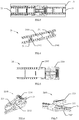
FIG. 1 and FIG. 2 are perspective views illustration of a lighting system with a suspension assembly in different operation states according to one embodiment; -
FIG. 3 is an enlarged view of portion A illustrated inFIG. 1 ; -
FIG. 4 is a perspective view illustration of a first section of the suspension assembly illustrated inFIG. 1 ; -
FIG. 5 is a front view illustration of a second section of the suspension assembly illustrated inFIG. 1 ; -
FIG. 6 and FIG. 7 are perspective views illustration of a positioning portion of the second section illustrated inFIG. 5 ; -
FIG. 8 and FIG. 9 are perspective views illustration of a lighting system with a suspension assembly in different operation states according to another embodiment; -
FIG. 10 is an enlarged view of portion B illustrated inFIG. 8 ; -
FIG. 11 is a front view illustration of a first section of the suspension assembly illustrated inFIG. 8 ; -
FIG. 12 is a front view illustration of a second section of the suspension assembly illustrated inFIG. 8 ; -
FIG. 13 is a side view illustration of a second section of the suspension assembly illustrated inFIG. 8 ; -
FIG. 14 and FIG. 15 are perspective views illustration of a lighting system with a suspension assembly in different operation states according to another embodiment; -
FIG. 16 is an enlarged view of portion E illustrated inFIG. 14 ; -
FIG. 17 is a perspective view illustration of a first section of the suspension assembly illustrated inFIG. 14 ; and -
FIG. 18 is a perspective view illustration of the lighting module and a second section of the suspension assembly illustrated inFIG. 14 . - Unless defined otherwise, technical and scientific terms used herein have the same meaning as is commonly understood by one of ordinary skill in the art to which this disclosure belongs. The terms "a" and "an" do not denote a limitation of quantity, but rather denote the presence of at least one of the referenced items. The use of "including," "comprising" or "having" and variations thereof herein are meant to encompass the items listed thereafter and equivalents thereof as well as additional items. The terms "connected" and "coupled" are not restricted to physical or mechanical connections or couplings, and can include electrical connections or couplings, whether direct or indirect.
- Generally, embodiments of the disclosure provide a lighting system. It may be a separate component in various application, including cabinet signs, doubled-sided box signs, and other like applications built for use with lighting fixtures. The suspension assembly involved in the lighting system is simply to adjust for multiple depths after installation, easy connection for uniformity spacing among lighting modules, and simple maintenance.
- Now, referring to the drawings wherein identical reference numerals denote the same elements throughout the various views,
FIGS. 1 and 2 depict an exemplary embodiment of alighting system 1 with asuspension assembly 20 in different operation states. Thelighting system 1 further includes at least twolighting modules 10, thesuspension assembly 20 is longitudinally attached to each twoadjacent lighting modules 10 from top to bottom. According to the exemplary lighting system illustrated herein, thesuspension assembly 20 connects with twoadjacent lighting modules 10 at both lateral ends of theadjacent lighting modules 10, so as to keep thelighting modules 10 as connected be relatively stable, and to easily balance a longitudinal distance D between the twoadjacent lighting modules 10, i.e., evenly spaced from one another in a direction parallel to a longitudinal axis C. - The
suspension assembly 20 in the exemplary lighting system illustrated herein is fixed, such as by gluing or welding, to each twoadjacent lighting modules 10. Thesuspension assembly 20 may be integrally formed with thelighting modules 10. - Each
lighting modules 10 generally includes a plurality oflight emitting elements 11, such as light emitting diodes (LEDs), which are electrically coupled to one another and are mounted on a printed circuit board (PCB) 12. Thelighting system 1 also includes at least one flexibleelectrical conductor 30 which is electrically and mechanically connected to thelighting modules 10 for supplying power to the LEDs mounted on thePCBs 12. When thesuspension assembly 20 adjust the longitudinal distance D between twoadjacent lighting modules 10, the flexibleelectrical conductor 30 may be pulled (shown inFig. 1 ) or loosen (shown inFig. 2 ). - Referring to
FIG. 3 , thesuspension assembly 20 in this exemplary embodiment as illustrated includes afirst section 21 and asecond section 22, which are mechanically connected. Thefirst section 21 is attached to one of the twoadjacent lighting modules 10 and the correspondingsecond section 22 is attached to the other one. - Referring to
FIG. 4 , thefirst section 21 in this exemplary embodiment as illustrated includes a plurality ofbackstop elements 211 along the length of thefirst section 21. Eachbackstop element 211, projecting from anouter surface 2103 of thefirst section 21, includes asliding surface 2111 with a smaller slope relative to theouter surface 2103 and abackstop surface 2112 with a larger slope, even perpendicular to theouter surface 2103 of thefirst section 21. - Referring to
FIG. 5 , thesecond section 22 in this exemplary embodiment as illustrated includes apositioning portion 2201 configured for corresponding to thebackstop elements 211 so as to put thefirst section 21 at a desirable position. Thesecond section 22 further includes a slidingportion 2202 configured for thefirst section 21 to slide thereon along the length of thesecond section 22. - Referring to
FIGS. 4, 5, 6 and 7 , thepositioning portion 2201 includes apositioning channel 222 configured for thefirst section 21 to get in and out thereof, anabutment element 221 configured for corresponding to thebackstop elements 211, anelastic control element 223 for controlling theabutment element 221. Theelastic control element 223 includes acontrol button 2231 for being pressed, and adriving arm 2232 connecting with theabutment element 221 and thecontrol button 2231. When the control button 2233 is pressed, theabutment element 221 will be in response to thecontrol button 2231 through thedriving arm 2232. - Specifically, the
first section 21 gets through thepositioning channel 222 and moves ahead by sliding onto the slidingportion 2202. During sliding, theabutment element 221 contacts with thebackstop element 211, i.e., theabutment element 221 slides across thesliding surface 2111, then slides back to abut thebackstop surface 2112 if needed, so as to fix thefirst section 21 at a desirable position. When it needs to adjust the relative position between the first section 21' and the second section 22', thecontrol button 2231 of theelastic control element 223 is pressed so thatabutment element 221 is driven to not abut thebackstop element 211, i.e., is controlled to release from thebackstop elements 211 which fixes thefirst section 21 in previous positon. It is understood that theabutment element 221 is controlled to be ready to correspond to thebackstop elements 211 when thefirst section 21 gets in thepositioning channel 222 and theelastic control element 223 is not pressed; and theabutment element 221 is controlled to release from thebackstop elements 211 when theelastic control element 223 is pressed. - Referring to
FIGS. 4, 5 and 7 , Thefirst section 21 further includes a plurality offlanges 2102 which position at edges of thefirst section 21 and extend against theouter surface 2103 of thefirst section 21. During sliding, theflanges 2102 contacts with the slidingportion 2202 of thesecond section 22 and provides frictional force so as to prevent from skidding. -
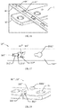
FIGS. 8 and 9 illustrate another example of a lighting system 1' with a suspension assembly 20' in different operation states. The lighting system 1' also includes at least twolighting modules 10, the suspension assembly 20' is longitudinally attached to each twoadjacent lighting modules 10 from top to bottom, and is configured to keep thelighting modules 10 as connected be relatively stable as well as to easily balance a longitudinal distance D between the twoadjacent lighting modules 10, i.e., evenly spaced from one another in a direction parallel to a longitudinal axis C. The lighting system 1' also includes at least one flexibleelectrical conductor 30 which is electrically and mechanically connected to thelighting modules 10 for supplying power to theLEDs 11 mounted on the PCBs. When the suspension assembly 20' adjust the longitudinal distance D between twoadjacent lighting modules 10, the flexibleelectrical conductor 30 may be pulled (shown inFig. 8 ) or loosen (shown inFig. 9 ). - Referring to
FIG. 10 , the suspension assembly 20' in this exemplary embodiment as illustrated includes a first section 21' and a second section 22', which are mechanically connected. The first section 21' is attached to one of the twoadjacent lighting modules 10 and the corresponding second first section 22' is attached to the other one. - Referring to
FIG.11 , the first section 21' in this exemplary embodiment as illustrated includes a plurality of positioning portions 2101' along the length of the first section 21'. Each positioning portions 2101', integrally formed by one through-hole on an outer surface 2102' of the first section 21', includes abackstop element 211' with a first inner width w1, an elastic transition region 213' with a second inner width w2 and a positioning element 212' with a third inner width w3. Preferably, the first inner width w1 is smaller than the third inner width w3 and the first inner width w1 is not smaller than the second inner width w2. As illustrated inFIG. 11 , the second inner width w2 is smaller than the first inner width w1. - Referring to
FIGS.12 and 13 , the second section 22' in this exemplary embodiment as illustrated includes a plurality of protrusion portions 2201' along the length of the second section 22'. Each protrusion portions 2201', integrally projecting from an outer surface 2202' of the second section 22', includes a first abutment element 221' with a first outer width w1' and asecond abutment element 222'. with a second outer width w2'. Preferably, the first outer width w1' is smaller than the second outer width w2'. Furthermore, the first outer width w1' is not smaller than the second inner width w2, the first outer width w1' is smaller than the first inner width w1, the third inner width w3 is smaller than the second outer width w2'. - Referring to
FIGS. 10, 11, 12 and 13 , the positioning element 212' is configured for the protrusion portions 2201' to get in and out thereof, thebackstop element 211' is configured for corresponding to both of the first abutment element 221' and the second abutment element 222'. Specifically, when the protrusion portions 2201' get in the positioning element 212', i.e., the second abutment element 222' gets through the positioning element 212' where the first abutment element 221' follows, the first abutment element 221' will get through the elastic transition region 213' to thebackstop element 211' under the force of pulling from top to bottom along the y direction. Meanwhile, the second abutment element 222' and the outer surface 2202'of the second section 22' defines the displacement that the first abutment element 221' may take place along the z direction so that the protrusion portions 2201' may be fixed in thebackstop element 211', then both of the first section 21' and the second section 22' can be defined in a desirable position. When it needs to adjust the relative position between the first section 21' and the second section 22', the first abutment element 221' will get through the elastic transition region 213' to the positioning element 212' under the force of pulling from bottom to top along the y direction, then get out from the positioning portion 2101'. Accordingly, the protrusion portions 2201' of the second section 22' that was fixed in specific positioning portions 2101' of the first section 21' can be released from the previous position and can be re-positioned by selecting other desirable positioning portions 2101' of the first section 21'. -
FIGS. 14 and 15 illustrate another example of alighting system 1" with asuspension assembly 20" in different operation states. Thelighting system 1" also includes at least twolighting modules 10", thesuspension assembly 20" is longitudinally attached to each twoadjacent lighting modules 10" from top to bottom, and is configured to keep thelighting modules 10" as connected be relatively stable as well as to easily balance a longitudinal distance D between the twoadjacent lighting modules 10", i.e., evenly spaced from one another in a direction parallel to a longitudinal axis C. Thelighting system 1" also includes at least one flexibleelectrical conductor 30 which is electrically and mechanically connected to thelighting modules 10" for supplying power to theLEDs 11 mounted on thelighting modules 10". When thesuspension assembly 20" adjust the longitudinal distance D between twoadjacent lighting modules 10", the flexibleelectrical conductor 30 may be pulled (shown inFig. 14 ) or loosen (shown inFig. 15 ). - Referring to
FIG. 16 , thesuspension assembly 20" in this exemplary embodiment as illustrated includes afirst section 21" and asecond section 22", which are mechanically connected. Thefirst section 21" is attached to both of the twoadjacent lighting modules 10" and the corresponding secondfirst section 22" is fastened with both of the twoadjacent lighting modules 10". - Referring to
FIG.17 , thefirst section 21" in this exemplary embodiment as illustrated includes a plurality ofpositioning portions 2101" along the length of thefirst section 21". Eachpositioning portions 2101", integrally formed by one through-hole on anouter surface 2102" of thefirst section 21", includes abackstop element 211" with a first inner width w1", anelastic transition region 213" with a second inner width w2" and apositioning element 212" with a third inner width w3". Preferably, the first inner width w1" is smaller than the third inner width w3" and the first inner width w1" is not smaller than the second inner width w2". As illustrated inFIG. 17 , the second inner width w2" is smaller than the first inner width w1". - Referring to
FIGS. 18 , thesecond section 22" in this exemplary embodiment as illustrated includes a plurality ofprotrusion portions 2201" along the width of thelighting modules 10". Eachprotrusion portions 2201", integrally projecting from anouter surface 101" of thelighting modules 10", includes afirst abutment element 221" with a first outer width w1"' and asecond abutment element 222" with a second outer width w2"'. Preferably, the first outer width w1"' is smaller than the second outer width w2"'. Furthermore, the first outer width w1"' is not smaller than the second inner width w2", the first outer width w1"' is smaller than the first inner width w1", the third inner width w3" is smaller than the second outer width w2"'. - Referring to
FIGS. 16, 17 and 18 , thepositioning element 212" is configured for theprotrusion portions 2201" to get in and out thereof, thebackstop element 211" is configured for corresponding to both of thefirst abutment element 221" and the second abutment element 222', the specific operation manner of these elements is as same as the embodiment shown inFIGS. 10 to 13 as described above. - While the invention has been described with reference to exemplary embodiments, it will be understood by those skilled in the art that various changes may be made and equivalents may be substituted for elements thereof without departing from the scope of the invention. Furthermore, the skilled artisan will recognize the interchangeability of various features from different embodiments. Similarly, the various method steps and features described, as well as other known equivalents for each such methods and feature, can be mixed and matched by one of ordinary skill in this art to construct additional assemblies and techniques in accordance with principles of this disclosure. In addition, many modifications may be made to adapt a particular situation or material to the teachings of the invention without departing from the essential scope thereof. Therefore, it is intended that the invention not be limited to the particular embodiment disclosed as the best mode contemplated for carrying out this invention, but that the invention will include all embodiments falling within the scope of the appended claims.
Claims (15)
- A lighting system (1, 1'), comprising:at least two lighting modules (10), each lighting modules having a plurality of light emitting elements (11) which are electrically coupled to one another; anda suspension assembly (20), configured for longitudinally attaching to the at least two lighting modules (10) to be arranged as two lighting modules adjacent to each other, the suspension assembly (20) comprising:a first section (21, 21') configured for attaching to one of the two adjacent lighting modules; anda second section (22, 22') configured for attaching to the other one of the two adjacent lighting modules;wherein the first section (21, 21') and the second section (22, 22') are mechanically connected for adjusting the longitudinal distance (D) between the two adjacent lighting modules.
- The lighting system (1) of claim 1, wherein
the first section (21) comprises a plurality of backstop elements (211) along the length of the first section (21); and
the second section (22) comprises a positioning portion (2201) having an abutment element (221) configured for corresponding to the backstop elements (211), and a positioning channel (222) configured for the first section (21) to get in and out thereof. - The lighting system (1) of claim 2, wherein
the positioning portion (2201) further comprises an elastic control element (223) for controlling the abutment element (221);
wherein the abutment element (221) is controlled to be ready to correspond to the backstop elements (211) when the first section (21) gets in the positioning channel (222) and the elastic control element (223) is not pressed; and the abutment element (221) is controlled to release from the backstop elements (211) when the elastic control element (223) is pressed. - The lighting system (1) of claim 2, wherein
the second section (22) further comprises a sliding portion (2202) configured for the first section (21) to slide thereon along the length of the second section (22). - The lighting system (1) of claim 4, wherein
the first section (21) further comprises a plurality of flanges (2102) configured for contacting with the sliding portion (2202). - The lighting system (1') of any preceding claim, wherein
the first section (21') comprises a plurality of positioning portions (2101') along the length of the first section (21'), each positioning portions (2101') comprising backstop element (211') and positioning element (212');
the second section (22') comprises a plurality of protrusion portions (2201') along the length of the second section (22'), each protrusion portions (2201') comprising a first abutment element (221') and a second abutment element (222');
wherein the positioning element (212') is configured for the protrusion portions (2201') to get in and out thereof, the backstop element (211') is configured for corresponding to both of the first abutment element (221') and the second abutment element (222'). - The lighting system (1') of claim 6, wherein
each positioning portions (2101') is integrally formed by one through-hole comprising the backstop element (211') with a first inner width (w1), an elastic transition region (213') with a second inner width (w2), and the positioning element (212') with a third inner width (w3);
wherein the first inner width (w1) is smaller than the third inner width (w3) and the first inner width (w1) is not smaller than the second inner width (w2). - The lighting system (1') of claim 7, wherein
each protrusion portions (2201') is integrally formed at least by the first abutment element (221') with a first outer width (w1') and the second abutment element (222') with a second outer width (w2');
wherein the first outer width (w1') is smaller than the second outer width (w2'), the first outer width (w1') is not smaller than the second inner width (w2), the first outer width (w1') is smaller than the first inner width (w1) and the third inner width (w3) is smaller than the second outer width (w2'). - The lighting system (1') of claim 6, wherein
the backstop element (211') is controlled to correspond to the first abutment element (221') and the second abutment element (222') when the protrusion portion (2201') gets in the positioning portion (2101') and the first abutment element (221') is contained in the backstop element (211'). - The lighting system (1') of claim 9, wherein
the backstop element (211') is controlled to release the first abutment element (221') and the second abutment element (222') when the protrusion portion (2201') gets out from the positioning portion (2101'). - A lighting system (1"), comprising:at least two lighting modules (10"), each lighting modules having a plurality of light emitting elements (11) which are electrically coupled to one another; anda suspension assembly (20"), configured for longitudinally attaching to the at least two lighting modules (10") to be arranged as two lighting modules adjacent to each other, the suspension assembly (20") comprising:a first section (21") configured for attaching to both of the two adjacent lighting modules; anda second section (22") configured for fastening with both of the two adjacent lighting modules;wherein the first section (21, 21') and the second section (22, 22') are mechanically connected for adjusting the longitudinal distance (D) between the two adjacent lighting modules.
- The lighting system (1") of claim 11, wherein
the first section (21") comprises a plurality of positioning portions (2101") along the length of the first section (21"), each positioning portions (2101") comprising backstop element (211") and positioning element (212");
the second section (22") comprises a plurality of protrusion portions (2201") along the width of the lighting module (10"), each protrusion portions (2201") comprising a first abutment element (221") and a second abutment element (222");
wherein the positioning element (212") is configured for the protrusion portions (2201") to get in and out thereof, the backstop element (211") is configured for corresponding to both of the first abutment element (221") and the second abutment element (222"). - The lighting system (1") of claim 12, wherein
each positioning portions (2101") is integrally formed by one through-hole comprising the backstop element (211") with a first inner width (w1"), an elastic transition region (213") with a second inner width (w2"), and the positioning element (212") with a third inner width (w3 ");
wherein the first inner width (w1") is smaller than the third inner width (w3") and the first inner width (w1") is not smaller than the second inner width (w2"). - The lighting system (1") of claim 13, wherein
each protrusion portions (2201") is integrally formed at least by the first abutment element (221") with a first outer width (w1"') and the second abutment element (222") with a second outer width (w2"');
wherein the first outer width (w1"') is smaller than the second outer width (w2"'), the first outer width (w1"') is not smaller than the second inner width (w2"), the first outer width (w1"') is smaller than the first inner width (w1") and the third inner width (w3") is smaller than the second outer width (w2"'). - The lighting system (1") of claim 12, wherein
the backstop element (211") is controlled to correspond to the first abutment element (221") and the second abutment element (222") when the protrusion portion (2201") gets in the positioning portion (2101") and the first abutment element (221") is contained in the backstop element (211"); and
the backstop element (211") is controlled to release the first abutment element (221") and the second abutment element (222") when the protrusion portion (2201") gets out from the positioning portion (2101").
Applications Claiming Priority (1)
| Application Number | Priority Date | Filing Date | Title |
|---|---|---|---|
| CN201710691583.0A CN109386766A (en) | 2017-08-14 | 2017-08-14 | Lighting system |
Publications (1)
| Publication Number | Publication Date |
|---|---|
| EP3447755A1 true EP3447755A1 (en) | 2019-02-27 |
Family
ID=63173981
Family Applications (1)
| Application Number | Title | Priority Date | Filing Date |
|---|---|---|---|
| EP18187794.5A Withdrawn EP3447755A1 (en) | 2017-08-14 | 2018-08-07 | Lighting system |
Country Status (3)
| Country | Link |
|---|---|
| US (1) | US10527266B2 (en) |
| EP (1) | EP3447755A1 (en) |
| CN (1) | CN109386766A (en) |
Families Citing this family (1)
| Publication number | Priority date | Publication date | Assignee | Title |
|---|---|---|---|---|
| WO2021042259A1 (en) * | 2019-09-03 | 2021-03-11 | 卡任特照明解决方案有限公司 | Mounting assembly, illumination system and method for fixing mounting strap |
Citations (4)
| Publication number | Priority date | Publication date | Assignee | Title |
|---|---|---|---|---|
| US20080244944A1 (en) * | 2006-10-05 | 2008-10-09 | Lumination, Llc | LED backlighting system for cabinet sign |
| US20090073693A1 (en) * | 2007-09-17 | 2009-03-19 | Nall Jeffrey M | Led lighting system for a cabinet sign |
| US20100238663A1 (en) * | 2009-03-18 | 2010-09-23 | Shun-Chih Chen | Adjustable Light-Emitting Diode Display Module |
| US20140268786A1 (en) * | 2013-03-15 | 2014-09-18 | The Sloan Company, Inc. Dba Sloanled | Sign box lighting system |
Family Cites Families (24)
| Publication number | Priority date | Publication date | Assignee | Title |
|---|---|---|---|---|
| CN88203598U (en) * | 1988-02-15 | 1988-12-14 | 何浩华 | belt fastening device |
| US5404282A (en) * | 1993-09-17 | 1995-04-04 | Hewlett-Packard Company | Multiple light emitting diode module |
| US5559681A (en) * | 1994-05-13 | 1996-09-24 | Cnc Automation, Inc. | Flexible, self-adhesive, modular lighting system |
| CN2241729Y (en) * | 1995-12-11 | 1996-12-04 | 黄朝明 | The clamping structure of the telescopic rod of the tripod |
| US6793369B2 (en) * | 2002-05-31 | 2004-09-21 | Tivoli Llc | Light fixture |
| US7528421B2 (en) * | 2003-05-05 | 2009-05-05 | Lamina Lighting, Inc. | Surface mountable light emitting diode assemblies packaged for high temperature operation |
| US7377669B2 (en) * | 2005-03-28 | 2008-05-27 | U.S. Led, Ltd. | LED module and system of LED modules with integral branch connectors |
| CN2825026Y (en) * | 2005-08-29 | 2006-10-11 | 陈伟成 | Roller Skate Telescopic Fixture |
| US8398261B2 (en) * | 2005-12-30 | 2013-03-19 | Ge Lighting Solutions Llc | Lighting strips with improved manufacturability |
| US9341328B2 (en) * | 2006-09-27 | 2016-05-17 | Osram Gesellschaft Mit Beschrankter Haftung | Method of producing a light emitting diode arrangement and light emitting diode arrangement |
| DE102007003809B4 (en) * | 2006-09-27 | 2012-03-08 | Osram Ag | A method of manufacturing a light emitting diode array and light emitting diode array having a plurality of LED modules arranged in a chain |
| EP2070071B1 (en) * | 2006-10-05 | 2016-11-16 | GE Lighting Solutions, LLC | Led backlighting system for cabinet sign |
| US7887218B2 (en) * | 2006-10-17 | 2011-02-15 | Baoliang Wang | LED illuminating device |
| US8186855B2 (en) * | 2007-10-01 | 2012-05-29 | Wassel James J | LED lamp apparatus and method of making an LED lamp apparatus |
| US8132935B2 (en) * | 2008-09-01 | 2012-03-13 | Samsung Led Co., Ltd. | Light emitting module |
| US20120155085A1 (en) * | 2010-12-20 | 2012-06-21 | Chih-Yang Chang | Led module assembling structure |
| EP2503221A3 (en) * | 2011-03-23 | 2013-03-06 | Toshiba Lighting & Technology Corporation | Light-emitting module, light-emitting module unit, and luminaire |
| US8449145B1 (en) * | 2011-05-04 | 2013-05-28 | Universal Lighting Technologies, Inc. | Mounting apparatus for a light emitting diode module |
| US9539932B2 (en) * | 2012-03-22 | 2017-01-10 | Lux Lighting Systems, Inc. | Light emitting diode lighting system |
| CN203028909U (en) * | 2012-10-12 | 2013-07-03 | 上海华森葳教育用品有限公司 | Board with holes, connecting piece and hanging piece containing connecting piece |
| CN202932662U (en) * | 2012-10-24 | 2013-05-15 | 何军 | Convenient clothes hanger |
| CN204743178U (en) * | 2015-05-28 | 2015-11-11 | 天元机器股份有限公司 | Screw-free shelf |
| CN205807140U (en) * | 2016-06-28 | 2016-12-14 | 深圳市美斯特光电技术有限公司 | LED high shed light |
| CN206233445U (en) * | 2016-10-18 | 2017-06-09 | 杭州欧尔装饰工程有限公司 | A kind of Multifunctional hanging board keel |
-
2017
- 2017-08-14 CN CN201710691583.0A patent/CN109386766A/en active Pending
-
2018
- 2018-07-09 US US16/030,039 patent/US10527266B2/en active Active
- 2018-08-07 EP EP18187794.5A patent/EP3447755A1/en not_active Withdrawn
Patent Citations (4)
| Publication number | Priority date | Publication date | Assignee | Title |
|---|---|---|---|---|
| US20080244944A1 (en) * | 2006-10-05 | 2008-10-09 | Lumination, Llc | LED backlighting system for cabinet sign |
| US20090073693A1 (en) * | 2007-09-17 | 2009-03-19 | Nall Jeffrey M | Led lighting system for a cabinet sign |
| US20100238663A1 (en) * | 2009-03-18 | 2010-09-23 | Shun-Chih Chen | Adjustable Light-Emitting Diode Display Module |
| US20140268786A1 (en) * | 2013-03-15 | 2014-09-18 | The Sloan Company, Inc. Dba Sloanled | Sign box lighting system |
Also Published As
| Publication number | Publication date |
|---|---|
| US10527266B2 (en) | 2020-01-07 |
| CN109386766A (en) | 2019-02-26 |
| US20190049098A1 (en) | 2019-02-14 |
Similar Documents
| Publication | Publication Date | Title |
|---|---|---|
| US20150241034A1 (en) | LED Linear Lighting Kit | |
| EP2557359A1 (en) | A lighting module | |
| US9279544B1 (en) | LED linear lighting strip | |
| CN102870290B (en) | Led socket assembly | |
| EP2615700B1 (en) | Lighting module | |
| US8313212B1 (en) | Modular lighting system and method | |
| US8746933B2 (en) | Lighting apparatus | |
| US8398261B2 (en) | Lighting strips with improved manufacturability | |
| CN101689337A (en) | Wirelessly controlled light emitting display system | |
| US20180014423A1 (en) | Power supply system for shelving system | |
| KR20130018833A (en) | Solid state lighting assembly | |
| CN105090796A (en) | Lighting device and corresponding mounting housing, kit and method | |
| JP7573221B2 (en) | Light source unit and lighting fixture | |
| US10527266B2 (en) | Lighting system | |
| WO1994019809A1 (en) | Circuit component stand-off mount | |
| US10018333B1 (en) | Systems, methods, and devices for providing replaceable reflector inserts for an LED light fixture | |
| US10443824B2 (en) | Sign box lighting system | |
| KR200453138Y1 (en) | LED module assembly for lights | |
| CN108138820A (en) | Retaining element | |
| CN104379989A (en) | Connecting module, power supply module and connecting set for light strips | |
| US10690324B2 (en) | Apparatus for mounting a luminaire on a support | |
| EP2902697B1 (en) | Lighting appliance based on strip of lighting elements with magnetic coupling | |
| EP3594558B1 (en) | A method for installing lighting devices and corresponding lighting device | |
| TWI627798B (en) | Electrical circuit with lighting led | |
| US20180135835A1 (en) | Apparatus and method to self-align led modules in a luminaire and secure with a single fixation point |
Legal Events
| Date | Code | Title | Description |
|---|---|---|---|
| PUAI | Public reference made under article 153(3) epc to a published international application that has entered the european phase |
Free format text: ORIGINAL CODE: 0009012 |
|
| STAA | Information on the status of an ep patent application or granted ep patent |
Free format text: STATUS: THE APPLICATION HAS BEEN PUBLISHED |
|
| AK | Designated contracting states |
Kind code of ref document: A1 Designated state(s): AL AT BE BG CH CY CZ DE DK EE ES FI FR GB GR HR HU IE IS IT LI LT LU LV MC MK MT NL NO PL PT RO RS SE SI SK SM TR |
|
| AX | Request for extension of the european patent |
Extension state: BA ME |
|
| STAA | Information on the status of an ep patent application or granted ep patent |
Free format text: STATUS: THE APPLICATION IS DEEMED TO BE WITHDRAWN |
|
| 18D | Application deemed to be withdrawn |
Effective date: 20190828 |