EP3447589A1 - Wheel train mechanism of clock - Google Patents
Wheel train mechanism of clock Download PDFInfo
- Publication number
- EP3447589A1 EP3447589A1 EP17815365.6A EP17815365A EP3447589A1 EP 3447589 A1 EP3447589 A1 EP 3447589A1 EP 17815365 A EP17815365 A EP 17815365A EP 3447589 A1 EP3447589 A1 EP 3447589A1
- Authority
- EP
- European Patent Office
- Prior art keywords
- gear
- pinion
- train mechanism
- tooth
- gear train
- Prior art date
- Legal status (The legal status is an assumption and is not a legal conclusion. Google has not performed a legal analysis and makes no representation as to the accuracy of the status listed.)
- Granted
Links
Images








Classifications
-
- G—PHYSICS
- G04—HOROLOGY
- G04B—MECHANICALLY-DRIVEN CLOCKS OR WATCHES; MECHANICAL PARTS OF CLOCKS OR WATCHES IN GENERAL; TIME PIECES USING THE POSITION OF THE SUN, MOON OR STARS
- G04B13/00—Gearwork
- G04B13/02—Wheels; Pinions; Spindles; Pivots
- G04B13/027—Wheels; Pinions; Spindles; Pivots planar toothing: shape and design
-
- F—MECHANICAL ENGINEERING; LIGHTING; HEATING; WEAPONS; BLASTING
- F16—ENGINEERING ELEMENTS AND UNITS; GENERAL MEASURES FOR PRODUCING AND MAINTAINING EFFECTIVE FUNCTIONING OF MACHINES OR INSTALLATIONS; THERMAL INSULATION IN GENERAL
- F16H—GEARING
- F16H55/00—Elements with teeth or friction surfaces for conveying motion; Worms, pulleys or sheaves for gearing mechanisms
- F16H55/02—Toothed members; Worms
- F16H55/08—Profiling
-
- F—MECHANICAL ENGINEERING; LIGHTING; HEATING; WEAPONS; BLASTING
- F16—ENGINEERING ELEMENTS AND UNITS; GENERAL MEASURES FOR PRODUCING AND MAINTAINING EFFECTIVE FUNCTIONING OF MACHINES OR INSTALLATIONS; THERMAL INSULATION IN GENERAL
- F16H—GEARING
- F16H55/00—Elements with teeth or friction surfaces for conveying motion; Worms, pulleys or sheaves for gearing mechanisms
- F16H55/02—Toothed members; Worms
- F16H55/08—Profiling
- F16H55/0806—Involute profile
-
- G—PHYSICS
- G04—HOROLOGY
- G04B—MECHANICALLY-DRIVEN CLOCKS OR WATCHES; MECHANICAL PARTS OF CLOCKS OR WATCHES IN GENERAL; TIME PIECES USING THE POSITION OF THE SUN, MOON OR STARS
- G04B13/00—Gearwork
- G04B13/02—Wheels; Pinions; Spindles; Pivots
Definitions
- the present disclosure relates to a gear train mechanism of a timepiece.
- a timepiece includes a gear train mechanism formed by a plurality of gear devices which meshes with each other to transmit power generated in a power source while increasing and decreasing a speed of the power.
- the gear device includes a gear and a pinion which are fixed to a common shaft.
- the gear has a diameter and the number of teeth larger than those of the pinion.
- the gear of one gear device meshes with the pinion of another gear device.
- the gears and the pinions of these gear devices include an involute tooth profile or a circular arc tooth profile.
- Patent Literature 1 JP5520278B
- the present disclosure has been made in view of the above circumstance, and an object of the present disclosure is to provide a gear train mechanism of a timepiece formed by a gear having an involute tooth profile, which is easily manufactured, and a pinion that meshes with the gear.
- a gear train mechanism of a timepiece reduces a fluctuation in torque to be transmitted and stably operates.
- a gear train mechanism of a timepiece of this disclosure includes a gear including a tooth having a tooth profile of an involute curve; and a pinion including a tooth meshing with the tooth of the gear to transmit and receive a torque, wherein the torque to be transmitted from one of the gear and the pinion to the other of the gear and the pinion is substantially constant at least in a part of a first half of a meshing period of the gear and the pinion.
- a gear train mechanism of a timepiece of this disclosure is formed by a gear having an involute tooth profile, which is easily manufactured, and a pinion that meshes with the gear. Such a gear train mechanism of a timepiece reduces a fluctuation in torque to be transmitted and stably operates.
- Fig. 1A is a schematic diagram illustrating a gear train mechanism 1 of a portable timepiece (for example, watch) as one embodiment of the present disclosure at the start of the contact of a tooth 11 of a driving gear 10 and a tooth 21 of a driven pinion 20.
- the gear train mechanism 1 illustrated in the figure includes the gear 10 as a second wheel and the pinion 20 as a third wheel.
- the gear 10 meshes with the pinion 20 to transmit a torque from the gear 10 to the pinion 20 through a meshing point T at which the gear 10 meshes with the pinion 20.
- the pinion 20 rotates in an arrow direction (counterclockwise direction in Fig. 1A ) along with the rotation of the gear 10 in an arrow direction (clockwise direction in Fig. 1A ). By this rotation, the meshing point T draws a track L illustrated by a one dot chain line.
- the module size is defined by International Organization for Standard (ISO) as a unit for representing a size of a tooth.
- a tooth profile 12 of each tooth 11 is defined by an involute curve such that a pressure angle ⁇ 2 is set to 22 degrees.
- the pressure angle is defined by Japan Industrial Standard (JIS B 0102) as an angle formed by a radial line and a line tangent to a tooth profile at one point of a tooth face.
- a tooth profile 22 of each tooth 21 is defined by a constant torque curve having a substantial constant torque to be transmitted from a virtual gear to the pinion 20 in the meshing period from the start to the end of the meshing of the tooth 21 of the pinion 20 and the virtual gear.
- the constant torque curve meshes with the involute virtual gear having a pressure angle ⁇ 1 (for example, 23.5 degrees) larger than the pressure angle ⁇ 2 of the tooth 11.
- the torque to be transmitted from the gear 10 to the pinion 20 becomes substantially constant at least in a part of a first half (for example, approach contact range) of the meshing period of the tooth 11 of the gear 10 and the tooth 21 of the pinion 20.
- the distance between the rotation center of the gear 10 and the rotation center of the pinion 20 (center distance) is 3 mm, for example.
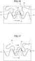
- Figs. 1B , 1C, 1D , IE, IF are schematic diagrams each illustrating the gear train mechanism 1.
- Fig. 1A, 1B , 1C illustrate the gear train mechanism 1 in the time-series order in the approach contact range in the first half of the above meshing period. Namely, Fig. 1A illustrates the gear train mechanism 1 at the meshing start, Fig. 1B illustrates the gear train mechanism 1 from the meshing start to the end of the approach contact, and Fig. 1C illustrates the gear train mechanism 1 at the end of the approach contact and the start of the recess contact.
- the approach contact and the recess contact are defined by Japan Industrial Standard (JIS B 0102).
- the approach contact is contact at any point on a path of contact between a pitch point and an addendum circle of a driven gear (pinion 20 in this embodiment).
- the recess contact is contact at any point on a path of contact between an addendum circle of a driving gear and a pitch point.
- Figs. 1C, 1D , IE, IF are schematic diagrams each illustrating the gear train mechanism 1.
- Figs. 1C, 1D , IE, IF illustrate the gear train mechanism 1 in the time-series order in the recess contact range in the second half of the above meshing period.
- Fig. 1C illustrates the gear train mechanism 1 at the end of the approach contact and the start of the recess contact
- Figs, 1D , IE illustrate the gear train mechanism 1 from the start of the recess contact to the end of the recess contact (part 1, part 2)
- Fig. IF illustrates the gear train mechanism 1 at the end of the recess contact.
- Fig. 1D is between Fig. 1C and Fig. 1E in the time-series order.
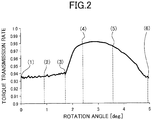
- Fig. 2 is a graph showing a transmission rate (transmission efficiency) of a torque from the gear 10 to the pinion 20 when the gear 10 meshes with the pinion 20 in the gear train mechanism 1 of the timepiece of this embodiment.
- the horizontal axis shows a rotation angle of the gear 10 and a vertical axis shows a torque transmission rate.
- (1) denotes the meshing illustrated in Fig. 1A
- (2) denotes the meshing illustrated in Fig. 1B
- (3) denotes the meshing illustrated in Fig. 1C
- (6) denotes the meshing illustrated in Fig. IF.
- the transmission rate of 1.0 shows 100 % transmission
- the transmission rate of 0.9 shows 90% transmission (hereinafter the same).
- the gear train mechanism 1 of the timepiece of this embodiment has a substantial constant transmission rate (0.93 to 0.94) of the torque to be transmitted from the gear 10 to the pinion 20 in the approach contact range (range of about 1.7 degrees of rotation angle of gear 10) illustrated in Figs. 1A, 1B , 1C .
- the gear train mechanism 1 of the timepiece of this embodiment also has a transmission rate of the torque to be transmitted from the gear 10 to the pinion 20 in the recess contact range (range of about 3.3 degrees of rotation angle of gear 10) illustrated in Figs. 1D , IE, IF.
- This transmission rate increases to be larger than that in the approach contact range, and decreases to about 0.93 to 0.94 in the approach contact range after exceeding 0.98.
- Fig. 3 is a graph showing the torque transmission rate (solid line) of the gear train mechanism 1 of the timepiece of this embodiment and the torque transmission rate (broken line) of a conventional gear train mechanism of a timepiece to which the present disclosure is not applied.
- the horizontal axis shows the rotation angle of the gear 10 and the vertical axis shows the torque transmission rate.
- the torque transmission rate of the gear train mechanism 1 of the timepiece of this embodiment shown by the solid line is the same as that shown in Fig. 2 .
- the torque transmission rate includes the minimum value T MIN and the maximum value T MAX .
- the conventional gear train mechanism of the timepiece illustrated by the broken line in Fig. 3 is a typical gear train mechanism formed by a gear having an involute tooth profile and a pinion having a tooth profile by ETA SA (not tooth profile of constant torque curve).
- the minimum value T MIN of the torque transmission rate of this gear train mechanism is slightly larger than 0.91, and this value is smaller than the minimum value T MIN of the torque transmission rate of the gear train mechanism 1 of this embodiment.
- the maximum value T MAX of the torque transmission rate of the typical gear train mechanism is substantially the same as the maximum value T MAX of the torque transmission rate of the gear train mechanism 1 of this embodiment.
- the gear train mechanism 1 of the timepiece of this embodiment has a substantial constant torque transmission rate with a tolerance value of 0.01 or below in the approach contact range in the meshing period of the gear 10 and the pinion 20.
- the minimum value of the torque transmission rate of the gear train mechanism 1 is larger than the minimum value of the torque transmission rate in the typical gear train mechanism of the timepiece to which the present disclosure is not applied as illustrated by the broken line of Fig. 3 .
- the torque fluctuation which is the difference between the maximum value and the minimum value of the torque transmission rates in the gear train mechanism 1 of the timepiece of the present disclosure reduces to be smaller than that of the conventional typical gear train mechanism of the timepiece, and the gear train mechanism 1 of the timepiece of this embodiment stably operates.
- the gear train mechanism 1 of the timepiece of the embodiment includes the pinion 20 having 8 teeth 21.
- the number Z of the teeth 21 on the pinion 20 is not limited to 8. It is preferable for the number Z of the teeth 21 on the pinion 20 to be 7 to 15. When the number Z of the teeth 21 on the pinion 20 is equal to 6 or less, the pinion 20 inappropriately meshes with the gear 10. On the other hand, when the number Z of the teeth 21 on the pinion 20 is equal to 16 or more, the torque fluctuation is not a significant issue for the gear train mechanism 1. When the number Z of the teeth 21 on the pinion 20 is 7, 8, 9, 10, 11, 12, 13, 14, 15, the pinion 20 appropriately meshes with the gear 10 and the torque fluctuation reduces. In these cases, the tooth profile 22 of the tooth 21 of the pinion 20 is defined by a constant torque curve in the period in which the pinion 20 meshes with the virtual gear having the large pressure angle ⁇ 1 as described above.
- the number Z of the teeth 21 on the pinion 20 of the gear train mechanism 1 is 7 to 10. In this case, the torque fluctuation further reduces.
- Fig. 4 is a graph showing correspondence of the number Z of teeth on the pinion 20 and the difference in pressure angle ⁇ .
- the gear 10 includes the tooth 11 having the tooth profile 12 defined by the involute curve, and the pressure angle ⁇ 1 is used for calculating the constant torque curve defining the tooth profile 22 of the tooth 21 of the pinion 20.
- the difference in pressure angle ⁇ is equal to - (Z / 2) + 5 or below, the addendum of the pinion 20 may contact the bottom of the gear 10.
- the difference in pressure angle ⁇ is larger than - (Z / 2) + 5
- the addendum of the pinion 20 may not contact the bottom of the gear 10.
- the torque transmission rate has a substantial constant value in the approach contact range and the maximum value in the recess contact range.
- the substantial constant value decreases and the maximum value increases in accordance with an increase in the difference in pressure angle ⁇ , resulting in an increase in the torque fluctuation which is the difference in torque transmission rate. Accordingly, when the difference in pressure angle ⁇ is equal to - (Z / 2) + 8 or more, the torque fluctuation does not significantly reduce.
- the difference in pressure angle ⁇ is smaller than - (Z / 2) + 8, the torque fluctuation further reduces.
- the pressure angle ⁇ 1 is used to calculate the constant torque curve defining the tooth profile 22 of the tooth 21 of the pinion 20.
- Such a difference ⁇ prevents the addendum of the pinion 20 from contacting a part of the gear 10 which is not required for torque transmission, for example, the bottom of the gear 10, achieving a gear train component of a timepiece having a substantial constant torque to be transmitted from the gear 10 to the pinion 20 at least in a part of the first half of the meshing period.
- the pinion 20 having the difference in pressure angle ⁇ smaller than 3.0 significantly reduces the torque fluctuation to be smaller than that of a pinion having the difference in pressure angle ⁇ smaller than 4.0.
- Fig. 5 is a graph corresponding to Fig. 2 .
- the graph in Fig. 5 shows the torque transmission rate when the difference in pressure angle ⁇ is changed to 1.5 degrees, 2 degrees, and 3 degrees in the gear train mechanism 1 of this embodiment (for example, pinion 20 has 8 teeth and gear 10 has 72 teeth meshing with pinion 20).
- the horizontal axis shows the rotation angle of the gear 10 and the vertical axis shows the torque transmission rate.
- the torque transmission rate when the difference in pressure angle ⁇ is 1.5 degrees in Fig. 5 is obtained by the gear train mechanism 1 of the above-described embodiment.
- the graph showing the torque transmission rate when the difference in pressure angle ⁇ is 1.5 degrees in Fig. 5 is the same as that in Fig. 2 .
- Fig. 5 shows the torque transmission rate when the difference in pressure angle ⁇ is changed to 1.5 degrees, 2 degrees, and 3 degrees in the gear train mechanism 1 of this embodiment (for example, pinion 20 has 8 teeth and gear 10 has 72 teeth meshing with pinion 20).
- the tooth profile of the tooth 11 of the gear 10 in the gear train mechanism 1 of this embodiment is defined by an involute curve such that the pressure angle ⁇ 2 is set to 22 degrees.
- this pressure angle ⁇ 2 is not limited to 22 degrees, and may be, for example, 18 degrees, 19 degrees, 20 degrees, 21 degrees, 23 degrees, 24 degrees, and 25 degrees in addition to 22 degrees.
- the pressure angles ⁇ 1, ⁇ 2 may be a value including a decimal point such as 22.5 degrees and 23.4 degrees.
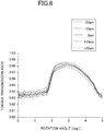
- Fig. 6 is a graph showing the torque transmission rates when the center distance between the gear 10 and the pinion 20 in the gear train mechanism 1 of the timepiece of this embodiment is changed by the shift amount ⁇ ⁇ m with respect to the normal 3 mm.
- the horizontal axis of the graph shows the rotation angle of the gear 10 and the vertical axis of the graph shows the torque transmission rate.
- the torque transmission rate shown by the solid line in Fig. 6 with the shift amount ⁇ of 0 ⁇ m is the same as that in the graph of Fig. 2 .
- the center distance is the normal 3 mm.
- the rough broken line in Fig. 6 shows the toque transmission rate when the shift amount ⁇ is + 10 ⁇ m which is longer than the normal center distance of 3 mm by 10 ⁇ m.
- the minimum torque transmission rate in the range of the constant torque transmission rate having a substantial constant torque transmission rate becomes larger than that when the center distance is the normal center distance and the maximum torque transmission rate in the range except the range of the constant torque transmission rate becomes smaller than that when the center distance is the normal center distance.
- the torque fluctuation therefore reduces to be smaller than that when the center distance is the normal center distance.
- the one dot chain line in Fig. 6 shows the torque transmission rate when the shift amount ⁇ is + 20 ⁇ m which is further longer than the shift amount ⁇ of + 10 ⁇ m by 10 ⁇ m.
- the minimum torque transmission rate in the range of the constant torque transmission rate becomes larger than that when the shift amount ⁇ is + 10 ⁇ m and the maximum torque transmission rate in the range except the range of the constant torque transmission rate becomes smaller than that when the shift amount ⁇ is + 10 ⁇ m.
- the torque fluctuation therefore further reduces to be smaller than that when the shift amount ⁇ of the center distance is + 10 ⁇ m.
- the dense broken line in Fig. 6 shows the torque transmission rate when the shift amount ⁇ is - 10 ⁇ m which is shorter than the normal center distance of 3 mm by 10 ⁇ m.
- the minimum torque transmission rate in the range of the constant torque transmission rate having a substantial constant torque rate becomes smaller than that when the center distance is the normal center distance and the maximum torque transmission rate in the range except the range of the constant torque transmission rate becomes larger than that when the center distance is the normal center distance.
- the torque fluctuation therefore increases to be larger than that when the center distance is the normal center distance.
- the fine broken line in Fig. 6 shows the torque transmission rate when the shift amount ⁇ is - 20 ⁇ m which is further shorter than the shift amount ⁇ of - 10 ⁇ m by 10 ⁇ m.
- the minimum torque transmission rate in the constant torque transmission rate becomes smaller than that when the shift amount ⁇ is - 10 ⁇ m and the maximum torque transmission rate in the range except the range of the constant torque transmission rate becomes larger than that when the shift amount ⁇ is - 10 ⁇ m.
- the torque fluctuation therefore further increases to be larger than that when the shift amount ⁇ is - 10 ⁇ m.
- the gear 10 In the range of the shift amount ⁇ of the center distance of - 20 ⁇ m to + 20 ⁇ m, the gear 10 normally meshes with the pinion 20, and the torque fluctuation does not significantly change. Accordingly, in the range of the shift amount ⁇ of the center distance of - 20 ⁇ m to + 20 ⁇ m, the torque fluctuation of the gear train mechanism 1 of the timepiece of this embodiment reduces to be smaller than that of a conventional gear train mechanism of a timepiece shown by the broken line in Fig. 3 .
- the gear train mechanism 1 of the timepiece of this embodiment is formed by the combination of the gear 10 as the second wheel and the pinion 20 as the third wheel.
- the gear train mechanism of the timepiece according to the present disclosure is not limited to this combination. More specifically, various combinations may be used, for example, combination of a gear as a third wheel and a pinion as a fourth wheel, combination of a gear as a fourth wheel and a pinion as an escape wheel, and combination of other gears.
- a specific method of setting the tooth profile 22 of the tooth 21 of the pinion 20 in the gear train mechanism 1 of the timepiece of the above embodiment is described hereinbelow.
- the pinion in the gear train mechanism of the timepiece according to the present disclosure is not limited to the one set by the following setting method.
- the following setting method is merely one example.
- Fig. 7 is a schematic diagram for describing a specific method of setting the tooth profile 22 of the tooth 21 of the pinion 20.
- Fig. 7 shows a virtual gear 10' having the pressure angle ⁇ 1 larger than the pressure angle of the gear 10 actually meshing with the pinion 20.
- O2 denotes the rotation center of the virtual gear 10'
- O1 denotes the rotation center of the pinion 20
- T denotes the meshing point of the pinion 20 and the virtual gear 10'
- L2 denotes the normal line (common normal line) of a common tangential line L1 of the tooth profile of the virtual gear 10' and the pinion 20 at the meshing point T
- P denotes the intersection point of the normal line L2 and a straight line L3
- ⁇ denotes a frictional angle.
- the normal line L2 is a normal line (common normal line) of the common tangential line L1 of the tooth profile of the virtual gear 10' and the pinion 20 at the meshing point T
- the straight line L3 connects the rotation centers O1, O2.
- Q denotes the intersection point of a straight line L4 and the straight line L3.
- the straight line L4 inclines at the friction angle ⁇ from the common normal line L2 at the meshing point T.
- ⁇ denotes the angle between the straight line L3 and the straight line L4, and a1, a2 denote the intersection point of the common tangential line L1 and each of perpendicular lines L5, L6 from each of the rotation centers O1, O2.
- R1 denotes the length from the rotation center O1 to the intersection point Q
- R2 denotes the length from the rotation center O2 to the intersection point Q
- P1 denotes the length from the rotation center O1 to the intersection point a1
- P2 denotes the length from the rotation center O2 to the intersection point a2.
- the lengths R1, R2 are set to be constant to rotate the pinion 20 with a substantial constant torque with respect to the virtual gear 10'.
- Tooth form curves F1, F2 are represented by polar tangential coordinates (P1, ⁇ 1) and polar tangential coordinates (P2, ⁇ 2), respectively, where L7 represent the straight line as a standard line connecting the rotation center O1 and an intersection point K1 of the virtually set tooth form curve F1 and a circle E1 having a radius R1 with the rotation center O1 as a center, ⁇ 1 represents the angle between the standard line L7 and the common tangential line L1, L8 represents the straight line as a standard line connecting the rotation center O2 and an intersection point K2 of the virtually set tooth form curve F2 and a circle E2 having a radius R2 with the rotation center O2 as a center, and ⁇ 2 represents the angle between the standard line L8 and the common tangential line L1.
- the tooth form curve F2 of the tooth 11 of the gear 10 is an involute.
- the polar tangential coordinates (P1, ⁇ 1) of the tooth form curve F1 as the constant torque curve to the involute curve are calculated based on the polar tangential coordinates (P2, ⁇ 2).
- ⁇ represent the pressure angle ⁇ 1 of the above-described virtual gear 10'.
- the tooth form curve F2 is obtained by the equations (1) to (7). More specifically, the polar coordinates (r, ⁇ ) corresponding to the path of the meshing point T are obtained by the equations (1), (3), (6), (7), and the polar tangential coordinates (P1, ⁇ 1) are obtained by substituting the obtained value into the equations (2), (4), (5).
- ⁇ 1 R 2 tan ⁇ ⁇ R 1 + R 2 ⁇ log Rg 2 t 2 ⁇ 2 R 1 + R 2 t + Rg 2 t 2 + 1 ⁇ 2 ⁇ R 1 tan ⁇ 1 t R 1 + R 2 + Rg 2 ⁇ R 1 R 1 + R 2 R 1 + R 2 2 ⁇ Rg 2 2 ⁇ log Rg 2 ⁇ t ⁇ R 1 + R 2 ⁇ R 1 + R 2 ⁇ Rg 2 2 Rg 2 ⁇ t ⁇ R 1 + R 2 + R 1 + R 1 + R 2 2 ⁇ Rg 2 2 + R 1 + R 2 + R 1 + R 2 2 ⁇ Rg 2 2 + c
- the constant term c in the equation (9) is obtained by substituting the initial value ⁇ into ⁇ 1 and the initial value ( ⁇ / 2 - ⁇ - ⁇ ) into ⁇ .
- the polar tangential coordinates (P1, ⁇ 1) defining the constant torque curve (tooth form curve F1) as the tooth profile of the pinion 20 are obtained.
- the constant torque curve (tooth form curve F1) corresponds to the involute curve (tooth form curve F2) as the tooth profile of the gear 10 defined by the polar tangential coordinates (P2, ⁇ 2).
- the obtained pinion 20 thereby has a substantial constant torque to be transmitted from the gear 10 with which the pinion 20 actually meshes at least in a part of the first half of the meshing period.
- the tooth profile 22 of the tooth 21 of the pinion 20 is defined by the constant torque curve having a substantial constant torque to be transmitted from the virtual gear 10' to the pinion 20 in the meshing period from the start to the end of the meshing of the virtual gear 10' and the tooth 21 of the pinion 20.
- the constant torque curve meshes with the involute virtual gear 10' having the pressure angle ⁇ 1 larger than the pressure angle ⁇ 2 of the tooth 11.
- the gear train mechanism of the present disclosure is not limited this configuration.
- the tooth profile 22 of the tooth 21 of the pinion 20 may be defined by the constant torque curve having a substantial constant torque to be transmitted from the virtual gear 10' to the pinion 20 in the meshing period from the start to the end of the meshing of the virtual gear 10' and the pinion 20.
- the constant torque curve meshes with the involute virtual gear 10' having the pressure angle ⁇ 1 smaller than the pressure angle ⁇ 2 of the tooth 11.
- the gear train mechanism 1 configured as described above may be Embodiment 2 of the gear train function of the present disclosure.
- the gear train mechanism 1 of Embodiment 2 configured as described above has the number Z of the teeth 21 on the pinion 20 in the range of 11 to 20, for example.
- the number Z of the teeth 21 having the tooth profile 22 defined by the constant torque curve in the meshing period with the virtual gear 10' having the small pressure angle ⁇ 1 is 11, 12, 13, 14, 15, 16, 17, 18, 19, 20, the torque fluctuation reduces while achieving appropriate meshing. It is more preferable for the number Z of the teeth 21 on the pinion 20 to be the range of 16 to 20 in order to further reduce the torque fluctuation.
- the difference in pressure angle ⁇ is larger than - (Z / 2) + 5, i.e., - (Z / 2) + 5 ⁇ ⁇ in the range of the number Z of the teeth 21 on the pinion 20 illustrated in Fig. 4 , i.e., in the range of 11, 12, 13, 14, 15, 16, 17, 18, 19, 20, in particular, in the range of 16 to 20.
- the difference in pressure angle ⁇ is smaller than - (Z / 2) + 8, i.e., ⁇ ⁇ - (Z / 2) + 8 in the range of the number Z of teeth on the pinion 20 illustrated in Fig. 4 , i.e., in the range of 11, 12, 13, 14, 15, 16, 17, 18, 19, 20, in particular, in the range of 16 to 20.
- the torque transmission rate has the substantial constant value in the approach contact range and the maximum value in the recess contact range.
- the difference in pressure angle ⁇ is ⁇ ⁇ - (Z / 2) + 7 in the range of the number of teeth Z on the pinion 20, i.e., in the range of 11, 12, 13, 14, 15, 16, 17, 18, 19, 20.
- ⁇ ⁇ - (Z / 2) +7 the torque fluctuation further reduces.
- the difference ⁇ between the pressure angle ⁇ 1 of the involute virtual gear 10' for use in the calculation of the constant torque curve defining the tooth profile 22 of the tooth 21 of the pinion 20 and the pressure angle ⁇ 2 of the gear 10, i.e., ⁇ ⁇ 1 - ⁇ 2, is set to be larger than - 3.5 and smaller than - 0.5 (preferably, smaller than - 1.5).
- a difference in pressure angle ⁇ prevents the addendum of the pinion 20 from contacting a part of the gear 10 (for example, bottom of gear 10) which is not required for torque transmission.
- the gear train component of the timepiece having a substantial constant torque to be transmitted from the gear 10 to the pinion 20 can be obtained.
- the pinion 20 has the preferable difference in pressure angle ⁇ of smaller than - 1.5, the torque fluctuation reduces to be smaller than that when the pinion 20 has the difference in pressure angle ⁇ of smaller than - 0.5.
- Fig. 8 is a graph showing the torque transmission rates corresponding to Fig. 5 .
- the torque transmission rates shown in Fig 8 are obtained when the difference in pressure angle ⁇ is changed to 0 degree, - 1 degree, and - 2 degrees in the gear train mechanism 1 of Embodiment 2 (the number Z of teeth on the pinion 20 is 17 and the number of teeth on the gear 10 meshing with the pinion 20 is 109, for example).
- the horizontal axis shows the rotation angle of the gear 10 and the vertical axis shows the torque transmission rate.
- the gear train mechanism of the timepiece of Embodiment 2 may be formed by various combinations such as the combination of the gear 10 as the second wheel and the pinion 20 as the third wheel, the combination of the gear as the third wheel and the pinion as the fourth wheel, the combination of the gear as the fourth wheel and the pinion as the escape wheel, the combination of the barrel wheel and the pinion as the second wheel, and the combination of the other gears.
- the gear train mechanism 1 of the Embodiment 1 includes the pinion 20 having the teeth 21 with a profile having the pressure angle ⁇ 1 ( ⁇ is positive) larger than the pressure angle ⁇ 2 of the teeth of the meshing gear 10.
- the number Z of teeth on the pinion 20 is preferably 7 to 15.
- the gear train mechanism 1 of Embodiment 2 includes the pinion 20 having the teeth 21 with a profile having the pressure angle ⁇ 1 ( ⁇ is negative) smaller than the pressure angle ⁇ 2 of the teeth of the meshing gear 10.
- the number Z of teeth on the pinion 20 is preferably 11 to 20.
- the pressure angle may be a pressure angle larger than the pressure angle ⁇ 2 of the teeth of the meshing gear 10, or a pressure angle smaller than the pressure angle ⁇ 2 of the teeth of the meshing gear 10.
- the pressure angle it is preferable for the pressure angle to be smaller than the pressure angle ⁇ 2 of the teeth of the meshing gear 10.
- the pinion 20 having 7 to 10 teeth is defined by the profile having the pressure angle ⁇ 1 ( ⁇ is positive) larger than the pressure angle ⁇ 2 of the teeth of the meshing gear 10.
- the pinion 20 having 16 to 20 teeth is defined by the profile having the pressure angle ⁇ 1 ( ⁇ is negative) smaller than the pressure angle ⁇ 2 of the teeth of the meshing gear 10.
- the pinion 20 having 11 to 15 teeth may be defined by a profile having the pressure angle ⁇ 1 ( ⁇ is positive) larger than the pressure angle ⁇ 2 of the teeth of the meshing gear 10, or a profile having a small pressure angle ⁇ 1 ( ⁇ is negative). It is more preferable for the pinion 20 to be defined by the profile having the pressure angle ⁇ 1 ( ⁇ is negative) smaller than the pressure angle ⁇ 2 of the teeth of the meshing gear.
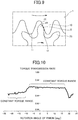
- Fig. 9 is a schematic view illustrating a gear train mechanism 1 of a portable timepiece (for example, watch) of Embodiment 3 of the present disclosure.
- the tooth 21 of the driving pinion 20 contacts the tooth 11 of the driven gear 10.
- the gear train mechanism 1 illustrated in Fig. 9 is formed by the pinion 20 and the gear 10 for use in a gear train mechanism which winds a power spring of a mechanical timepiece, for example.
- the pinion 20 meshes with the gear 10 to transmit a torque from the pinion 20 to the gear 10 through a meshing point T at which the pinion 20 contacts the gear 10.
- the gear 10 rotates in an arrow direction (counterclockwise direction in Fig. 9 ) by the rotation of the pinion 20 in an arrow direction (clockwise direction in Fig. 9 ).
- the tooth profile 12 of each tooth 11 is defined by the involute curve such that the pressure angle ⁇ 2 is set to 22 degrees.
- the tooth profile 22 of each tooth 21 is defined by a constant torque curve having a substantial constant torque to be transmitted from the pinion 20 to the virtual gear in the meshing period from the start to the end of the meshing of the tooth 21 of the pinion 20 and the virtual gear.
- the constant torque curve meshes with the involute virtual gear having the pressure angle ⁇ 1 (for example, 20 degrees) smaller than the pressure angle ⁇ 2 of the tooth 11.
- the torque to be transmitted from the pinion 20 to the gear 10 becomes substantially constant at least in a part of the first half (for example, approach contact range) of the meshing period of the tooth 11 of the gear 10 and the tooth 21 of the pinion 20.
- the torque to be transmitted from the pinion 20 to the gear 10 also becomes substantially constant at least in a part of the second half (for example, recess contact range) of the meshing period of the tooth 11 of the gear 10 and the tooth 21 of the pinion 20.
- the distance (center distance) between the rotation center of the gear 10 and the rotation center of the pinion 20 is 4.41 mm, for example.
- Fig. 10 is a graph illustrating a torque transmission rate from the pinion 20 to the gear 10 when the gear 10 meshes with the pinion 20 in the gear train mechanism 1 of Embodiment 3.
- the negative range of the rotation angle of the pinion 20 in the horizontal axis shows the first half of the meshing period
- the positive range of the rotation angle of the pinion 20 shows the second half of the meshing period.
- the gear train mechanism 1 of the timepiece of Embodiment 3 has a substantial constant torque transmission rate (0.94 to 0.95) to be transmitted from the pinion 20 to the gear 10 in a part of the approach contact (range of rotation angle of about 12 degrees (- 22 to - 10 degrees) of pinion 20).
- the gear train mechanism 1 of the timepiece of Embodiment 3 also has a substantial constant torque transmission rate (about 0.96) to be transmitted from the pinion 20 to the gear 10 in a part of the recess contact (range of rotation angle of about 25 degrees (- 8 to + 17 degrees) of pinion 20).
- Fig. 11 is a graph showing the torque transmission rate (solid line) of the gear train mechanism 1 of Embodiment 3 and the torque transmission rate (dashed line) of a conventional gear train mechanism of a timepiece to which the present disclosure is not applied.
- the horizontal axis shows the rotation angle of the pinion 20 and the vertical axis shows the torque transmission rate.
- the torque transmission rate of the gear train mechanism 1 of the timepiece of this embodiment shown by the solid line is the same as that illustrated in Fig. 10 .
- the torque transmission rate has the minimum value T MIN and the maximum value T MAX .
- the conventional gear train mechanism of the timepiece illustrated by the broken line in Fig. 11 is a typical gear train mechanism.
- the gear train mechanism is formed by a gear including an involute tooth profile and a pinion including a tooth profile by ETA SA (not profile of constant torque curve).
- the minimum value T MIN of the torque transmission rate is slightly larger than 0.92 and this value is smaller than the minimum value T MIN (slightly larger than 0.93) of the torque transmission rate in the gear train mechanism 1 of Embodiment 3.
- the maximum value T MAX of the torque transmission rate in the general gear train mechanism is slightly larger than 0.97, and this value is larger than the maximum value T MAX (slightly larger than 0.96) of the torque transmission rate in the gear train mechanism 1 of Embodiment 3.
- the gear train mechanism 1 of the timepiece of Embodiment 3 has a substantial constant torque transmission rate with a tolerance value of 0.01 or below both in a part of the approach contact and a part of the recess contact in the meshing period of the gear 10 and the pinion 20.
- the torque fluctuation which is the difference between the maximum value T MAX and the minimum value T MIN of the torque transmission rate in the gear train mechanism 1 of the timepiece of Embodiment 3 reduces to be smaller than that in the conventional gear train mechanism of the timepiece to which the present disclosure is not applied.
- the conventional gear train mechanism of the timepiece is represented by the broken line in Fig. 11 .
- the gear train mechanism 1 of the timepiece of Embodiment 3 stably operates.
- the gear train mechanism 1 of the timepiece of Embodiment 3 includes the pinion 20 having 8 teeth 21.
- the number Z of the teeth 21 on the pinion 20 is not limited to 8, and may be 7 to 12. As described above, when the number Z of the teeth 21 on the pinion 20 is equal to 6 or below and is equal to 13 or more, the pinion 20 inappropriately meshes with the gear 10. When the number Z of teeth 21 on the pinion is 7, 8, 9, 10, 11, 12, the torque fluctuation is effectively controlled while achieving the appropriate meshing.
- the tooth profile 22 of the tooth 21 of the pinion 20 is defined by the constant torque curve in the meshing period meshing with the virtual gear 10' having the small pressure angle ⁇ 1.
- Fig. 12 is a graph showing a torque transmission rate in the gear train mechanism 1 of the modified example.
- the gear train mechanism 1 includes the pinion 20 having 12 teeth 21, and a substantial constant torque to be transmitted from the pinion 20 to the gear 10 at least in a part of the first half of the meshing period of the gear 10 and the pinion 20 and at least in a part of the second half of the meshing period.
- the horizontal axis shows the rotation angle of the pinion 20 and the vertical axis shows the torque transmission rate.
- the torque transmission rate illustrated in Fig. 12 is obtained by the combination of the tooth 11 and the pinion 20.
- the tooth profile 12 of the tooth 11 is defined by the involute curve such that the pressure angle ⁇ 2 is set to 20 degrees.
- the pinion 20 meshes with the virtual gear corresponding to the involute tooth profile 22 of the tooth 21 having the pressure angle ⁇ 1 of 20 degrees.
- the pressure angle ⁇ 1 of the pinion 20 may be set to be equal to the pressure angle ⁇ 2 of the gear 10 as long as the pinion 20 has the substantial constant torque to be transmitted from the pinion 20 to the gear 10 at least in a part of the first half of the meshing period of the gear 10 and the pinion 20 and at least in a part of the second half of the meshing period.
- the fluctuation in torque to be transmitted from the pinion 20 to the gear 10 can be controlled as shown in Fig. 12 while achieving appropriate meshing.
- the number Z of the teeth 21 on the pinion 20 in the gear train mechanism 1 is more preferable for the number Z of the teeth 21 on the pinion 20 in the gear train mechanism 1 to be the range of 7 to 10. In this case, the torque fluctuation further reduces.
- Fig. 13 is a graph showing correspondence between the number Z of teeth on the pinion 20 and the difference in pressure angle ⁇ .
- the gear train mechanism 1 of the timepiece of Embodiment 3 prefferably has the difference in pressure angle ⁇ larger than (Z / 2) - 8 and smaller than (Z / 2) - 5, i.e., (Z / 2) - 8 ⁇ ⁇ ⁇ (Z / 2) - 5, in the range of the number Z of teeth on the pinion 20 shown in Fig. 13 , i.e., in the range of 7, 8, 9, 10, 11, 12.
- the difference in pressure angle ⁇ is smaller than (Z / 2) - 8 and larger than (Z / 2) - 5
- the addendum of the pinion 20 may contact the addendum of the gear 10, which may disturb the appropriate meshing.
- the number Z of teeth on the pinion 20 in the gear train mechanism 1 of the timepiece of Embodiment 3 is 7, 8, 9, 10 under the condition that the difference in pressure angle ⁇ is negative.
- the involute tooth profile of the tooth 11 of the gear 10 in the gear train mechanism 1 of Embodiment 3 has the pressure angle ⁇ 2 of 22 degrees.
- the involute tooth profile of the tooth of the gear in the gear train mechanism of the timepiece according to the present disclosure is not limited to have the pressure angle ⁇ 2 of 22 degrees.
- the pressure angle ⁇ 2 may be 18 degrees, 19 degrees, 20 degrees, 21 degrees, 23 degrees, 24 degrees, and 25 degrees in addition to 22 degrees.
- the pressure angles ⁇ 1, ⁇ 2 may be an angle including a decimal point such as 22.5 degrees, 23.4 degrees.
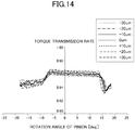
- Fig. 14 is a graph showing the torque transmission rate when the center distance between the gear 10 and the pinion 20 in the gear train mechanism 1 of the timepiece of Embodiment 3 is changed by the shift amount ⁇ a ⁇ m with respect to the normal center distance of 4.41 mm.
- the horizontal axis shows the rotation angle of the gear 10 and the vertical axis shows the torque transmission rate.
- the torque transmission rate when the shift amount ⁇ a is 0 ⁇ m which is shown by the solid line is the torque transmission rate when the center distance is the normal 4.41 mm which is the same as that in the graph of Fig. 10 .
- the rough short broken line of Fig. 14 shows the torque transmission rate when the shift amount ⁇ a is + 10 ⁇ m which is longer than the normal distance of 4.41 mm by 10 ⁇ m.
- the minimum torque transmission rate in the range of the substantial constant torque transmission rate, which is in the first half of the meshing period, is smaller than that when the center distance is the normal center distance
- the maximum torque transmission rate in the range of the substantial constant torque transmission rate, which is in the second half of the meshing period is larger than that when the center distance is the normal center distance.
- the torque fluctuation therefore increases to be larger than that when the center distance is the normal center distance.
- the short one dot chain line of Fig. 14 shows the torque transmission rate when the shift amount ⁇ a is + 20 ⁇ m which is longer than the shift amount ⁇ a of + 10 ⁇ m by 10 ⁇ m.
- the minimum torque transmission rate in the range of the substantial constant torque transmission rate, which is in the first half of the meshing period is smaller than that when the shift amount ⁇ a is + 10 ⁇ m
- the maximum torque transmission rate in the range of the substantial constant torque transmission rate, which is in the second half of the meshing period is larger than that when the shift amount ⁇ a is + 10 ⁇ m.
- the torque fluctuation therefore further increases to be larger than that when the shift amount ⁇ a is + 10 ⁇ m.
- the rough long broken line of Fig. 14 shows the torque transmission rate when the shift amount ⁇ a is + 30 ⁇ m which is longer than the shift amount ⁇ a of + 20 ⁇ m by 10 ⁇ m.
- the minimum torque transmission rate in the range of the substantial constant torque transmission rate, which is in the first half of the meshing period is smaller than that when the shift amount ⁇ a is + 20 ⁇ m
- the maximum torque transmission rate in the range of the substantial constant torque transmission rate, which is in the second half of the meshing period is larger than that when the shift amount ⁇ a is + 20 ⁇ m.
- the torque fluctuation therefore further increases to be larger than that when the shift amount ⁇ a is + 20 ⁇ m.
- the dense short broken line of Fig. 14 shows the torque transmission rate when the shift amount ⁇ a is - 10 ⁇ m which is shorter than the normal distance of 4.41 mm by 10 ⁇ m.
- the minimum torque transmission rate in the range of the substantial constant torque transmission rate, which is in the first half of the meshing period, is larger than that when the center distance is the normal center distance and the maximum torque transmission rate in the substantial constant torque transmission rate, which is in the second half of the meshing period, is smaller than that when the center distance is the normal distance.
- the toque fluctuation therefore reduces to be smaller than that when the center distance is the normal center distance.
- the long one dot chain line of Fig. 14 shows the torque transmission rate when the shift amount ⁇ a is - 20 ⁇ m which is shorter than the shift amount ⁇ a of - 10 ⁇ m by 10 ⁇ m.
- the minimum torque transmission rate in the range of the substantial constant torque transmission rate, which is in the first half of the meshing period is larger than that when the shift amount ⁇ a is - 10 ⁇ m
- the maximum torque transmission rate in the range the substantial constant torque transmission rate, which is in the second half of the meshing period is smaller than that when the shift amount ⁇ a is - 10 ⁇ m.
- the torque fluctuation therefore further reduces to be smaller than that when the shift amount ⁇ a is - 10 ⁇ m.
- the fine broken line of Fig. 14 shows the torque transmission rate when the shift amount ⁇ a is - 30 ⁇ m which is shorter than the shift amount ⁇ a of - 20 ⁇ m by 10 ⁇ m.
- the minimum torque transmission rate in the range of the substantial constant torque transmission rate, which is in the first half of the meshing period is larger than that when the shift amount ⁇ a is - 20 ⁇ m
- the maximum torque transmission rate in the range of the substantial constant torque transmission rate, which is in the second half of the meshing period is smaller than that when the shift amount ⁇ a is - 20 ⁇ m.
- the torque fluctuation therefore further reduces to be smaller than that when the shift amount ⁇ a is - 20 ⁇ m.
- the gear 10 in the range of the shift amount ⁇ a of - 30 ⁇ m to + 30 ⁇ m, the gear 10 appropriately meshes with the pinion 20, and the torque fluctuation does not significantly change. Accordingly, in the range of the shift amount ⁇ a of - 30 ⁇ m to + 30 ⁇ m, the torque fluctuation of the gear train mechanism 1 of the timepiece of Embodiment 3 reduces to be smaller than that of the conventional gear train mechanism shown by the dashed line in Fig. 11 .
- the gear train mechanism 1 of the timepiece of Embodiment 3 is formed by the combination of the pinion 20 and the gear 10 for use in the gear train mechanism which winds the power spring.
- the gear train mechanism of the timepiece of this disclosure is not limited to this combination.
- the gear train mechanism 1 of each of the embodiments and the modified example is merely one preferable example.
- the technical scope of the gear train mechanism of the present disclosure is not limited to each of these embodiments and the modified example.
Landscapes
- Engineering & Computer Science (AREA)
- General Engineering & Computer Science (AREA)
- Mechanical Engineering (AREA)
- Physics & Mathematics (AREA)
- General Physics & Mathematics (AREA)
- Gears, Cams (AREA)
- Gear Transmission (AREA)
Abstract
Description
- The present disclosure relates to a gear train mechanism of a timepiece.
- A timepiece includes a gear train mechanism formed by a plurality of gear devices which meshes with each other to transmit power generated in a power source while increasing and decreasing a speed of the power. The gear device includes a gear and a pinion which are fixed to a common shaft. The gear has a diameter and the number of teeth larger than those of the pinion. The gear of one gear device meshes with the pinion of another gear device.
- The gears and the pinions of these gear devices include an involute tooth profile or a circular arc tooth profile.
- When the gear meshes with the pinion to transmit a torque between the gear and the pinion, it is preferable for a fluctuation in toque to be transmitted to be as small as possible. A gear train mechanism having tooth profiles of a gear and a pinion defined by a specific calculation formula is therefore proposed (see
Patent Literature 1, for example). - Patent Literature 1:
JP5520278B - However, it is not easy to manufacture such a gear train mechanism because the gear train mechanism described in
Patent Literature 1 includes a gear and a pinion both having a tooth profile defined by the above calculation formula. - The present disclosure has been made in view of the above circumstance, and an object of the present disclosure is to provide a gear train mechanism of a timepiece formed by a gear having an involute tooth profile, which is easily manufactured, and a pinion that meshes with the gear. Such a gear train mechanism of a timepiece reduces a fluctuation in torque to be transmitted and stably operates.
- A gear train mechanism of a timepiece of this disclosure includes a gear including a tooth having a tooth profile of an involute curve; and a pinion including a tooth meshing with the tooth of the gear to transmit and receive a torque, wherein the torque to be transmitted from one of the gear and the pinion to the other of the gear and the pinion is substantially constant at least in a part of a first half of a meshing period of the gear and the pinion.
- A gear train mechanism of a timepiece of this disclosure is formed by a gear having an involute tooth profile, which is easily manufactured, and a pinion that meshes with the gear. Such a gear train mechanism of a timepiece reduces a fluctuation in torque to be transmitted and stably operates.
-
-
Fig. 1A is a schematic diagram illustrating a gear train mechanism of a portable timepiece (for example, watch) as one embodiment of the present disclosure at the start of contact (approach contact) of a tooth of a driving gear and a tooth of a driven pinion. -
Fig. 1B is a schematic diagram illustrating the gear train mechanism of the portable timepiece from the start of meshing to the end of the approach contact. -
Fig. 1C is a schematic diagram illustrating the gear train mechanism of the portable timepiece at the end of the approach contact and the start of recess contact. - Fig. ID is a schematic diagram illustrating the gear train mechanism of the portable timepiece from the start of the recess contact to the end of the recess contact (part 1).
- Fig. IE is a schematic diagram illustrating the gear train mechanism of the portable timepiece from the start of the recess contact to the end of the recess contact (part 2).
- Fig. IF is a schematic diagram illustrating the gear train mechanism of the portable timepiece at the end of the recess contact.
-
Fig. 2 is a graph showing a torque transmission rate from the gear to the pinion when the gear meshes with the pinion in the gear train mechanism of the timepiece according to the embodiment. -
Fig. 3 is a graph showing a torque transmission rate (solid line) of the gear train mechanism of the embodiment and a torque transmission rate (broken line) of a conventional gear train mechanism of a timepiece to which the present disclosure is not applied. -
Fig. 4 is a graph showing correspondence between the number of teeth on the pinion and a difference in pressure angle. -
Fig. 5 is a graph showing torque transmission rates corresponding toFig. 2 when the difference in pressure angle is changed to 1.5 degrees, 2 degrees, and 3 degrees in the gear train mechanism of the embodiment. -
Fig. 6 is a graph showing torque transmission rates when a center distance between the gear and the pinion in the gear train mechanism of the timepiece of the embodiment is changed by a shift amount Δa µm with respect to the normal 30 mm. -
Fig. 7 is a schematic diagram for describing a specific setting method of a tooth profile of a tooth of the pinion. -
Fig. 8 is a graph showing torque transmission rates corresponding toFig. 5 when the difference in pressure angle is changed to - 2 degrees, - 1 degree, and 0 degree in the gear train mechanism ofEmbodiment 2. -
Fig. 9 is a schematic diagram illustrating a gear train mechanism of a portable timepiece (for example, watch) ofEmbodiment 3, and illustrating the contact of a tooth of a driving pinion and a tooth of a driven gear. -
Fig. 10 is a graph showing a torque transmission rate from the pinion to the gear when the gear meshes with the pinion in the gear train mechanism ofEmbodiment 3. -
Fig. 11 is a graph showing a torque transmission rate (solid line) of the gear train mechanism ofEmbodiment 3 and a torque transmission rate (broken line) of a conventional gear train mechanism of a timepiece to which the present disclosure is not applied. -
Fig. 12 is a graph showing a torque transmission rate in a gear train mechanism of a modified example including a pinion having 12 teeth, the gear train mechanism being configured to have a substantial constant torque to be transmitted from the pinion to the gear at least in a part of a first half of the meshing period of the gear and the pinion and at least in a part of a second half of the meshing period. -
Fig. 13 is a graph showing correspondence between the number of teeth on the pinion and the difference in pressure angle Δα. -
Fig. 14 is a graph showing torque transmission rates when a center distance between the gear and the pinion in the gear train mechanism of the timepiece ofEmbodiment 3 is changed by the shift amount Δα µm with respect to the normal 4.41 mm. - Hereinafter, embodiments of a gear train mechanism of a timepiece according to the present disclosure are described with reference to the drawings.
-
Fig. 1A is a schematic diagram illustrating agear train mechanism 1 of a portable timepiece (for example, watch) as one embodiment of the present disclosure at the start of the contact of atooth 11 of adriving gear 10 and atooth 21 of a drivenpinion 20. Thegear train mechanism 1 illustrated in the figure includes thegear 10 as a second wheel and thepinion 20 as a third wheel. Thegear 10 meshes with thepinion 20 to transmit a torque from thegear 10 to thepinion 20 through a meshing point T at which thegear 10 meshes with thepinion 20. Thepinion 20 rotates in an arrow direction (counterclockwise direction inFig. 1A ) along with the rotation of thegear 10 in an arrow direction (clockwise direction inFig. 1A ). By this rotation, the meshing point T draws a track L illustrated by a one dot chain line. - The
gear 10 has 72teeth 11 and a module size, m = 0.075 mm, for example. The module size is defined by International Organization for Standard (ISO) as a unit for representing a size of a tooth. Atooth profile 12 of eachtooth 11 is defined by an involute curve such that a pressure angle α2 is set to 22 degrees. The pressure angle is defined by Japan Industrial Standard (JIS B 0102) as an angle formed by a radial line and a line tangent to a tooth profile at one point of a tooth face. - On the other hand, the
pinion 20 has 8teeth 21 and a module size, m = 0.075 mm, for example. Atooth profile 22 of eachtooth 21 is defined by a constant torque curve having a substantial constant torque to be transmitted from a virtual gear to thepinion 20 in the meshing period from the start to the end of the meshing of thetooth 21 of thepinion 20 and the virtual gear. In this case, the constant torque curve meshes with the involute virtual gear having a pressure angle α1 (for example, 23.5 degrees) larger than the pressure angle α2 of thetooth 11. Accordingly, the torque to be transmitted from thegear 10 to thepinion 20 becomes substantially constant at least in a part of a first half (for example, approach contact range) of the meshing period of thetooth 11 of thegear 10 and thetooth 21 of thepinion 20. The distance between the rotation center of thegear 10 and the rotation center of the pinion 20 (center distance) is 3 mm, for example. - The operation of the
gear train mechanism 1 constructed as described above is described.Figs. 1B ,1C, 1D , IE, IF are schematic diagrams each illustrating thegear train mechanism 1.Fig. 1A, 1B ,1C illustrate thegear train mechanism 1 in the time-series order in the approach contact range in the first half of the above meshing period. Namely,Fig. 1A illustrates thegear train mechanism 1 at the meshing start,Fig. 1B illustrates thegear train mechanism 1 from the meshing start to the end of the approach contact, andFig. 1C illustrates thegear train mechanism 1 at the end of the approach contact and the start of the recess contact. - The approach contact and the recess contact are defined by Japan Industrial Standard (JIS B 0102). The approach contact is contact at any point on a path of contact between a pitch point and an addendum circle of a driven gear (
pinion 20 in this embodiment). The recess contact is contact at any point on a path of contact between an addendum circle of a driving gear and a pitch point. -
Figs. 1C, 1D , IE, IF are schematic diagrams each illustrating thegear train mechanism 1.Figs. 1C, 1D , IE, IF illustrate thegear train mechanism 1 in the time-series order in the recess contact range in the second half of the above meshing period. Namely,Fig. 1C illustrates thegear train mechanism 1 at the end of the approach contact and the start of the recess contact,Figs, 1D , IE illustrate thegear train mechanism 1 from the start of the recess contact to the end of the recess contact (part 1, part 2), and Fig. IF illustrates thegear train mechanism 1 at the end of the recess contact. In addition,Fig. 1D is betweenFig. 1C andFig. 1E in the time-series order. -
Fig. 2 is a graph showing a transmission rate (transmission efficiency) of a torque from thegear 10 to thepinion 20 when thegear 10 meshes with thepinion 20 in thegear train mechanism 1 of the timepiece of this embodiment. In the graph, the horizontal axis shows a rotation angle of thegear 10 and a vertical axis shows a torque transmission rate. In the graph, (1) denotes the meshing illustrated inFig. 1A , (2) denotes the meshing illustrated inFig. 1B , (3) denotes the meshing illustrated inFig. 1C , (4) denotes the meshing illustrated inFig. 1D , (5) denotes the meshing illustrated in Fig, IE, and (6) denotes the meshing illustrated in Fig. IF. The transmission rate of 1.0 shows 100 % transmission, and the transmission rate of 0.9 shows 90% transmission (hereinafter the same). - According to the graph illustrated in
Fig. 2 , thegear train mechanism 1 of the timepiece of this embodiment has a substantial constant transmission rate (0.93 to 0.94) of the torque to be transmitted from thegear 10 to thepinion 20 in the approach contact range (range of about 1.7 degrees of rotation angle of gear 10) illustrated inFigs. 1A, 1B ,1C . - The
gear train mechanism 1 of the timepiece of this embodiment also has a transmission rate of the torque to be transmitted from thegear 10 to thepinion 20 in the recess contact range (range of about 3.3 degrees of rotation angle of gear 10) illustrated inFigs. 1D , IE, IF. This transmission rate increases to be larger than that in the approach contact range, and decreases to about 0.93 to 0.94 in the approach contact range after exceeding 0.98. -
Fig. 3 is a graph showing the torque transmission rate (solid line) of thegear train mechanism 1 of the timepiece of this embodiment and the torque transmission rate (broken line) of a conventional gear train mechanism of a timepiece to which the present disclosure is not applied. InFig. 3 , the horizontal axis shows the rotation angle of thegear 10 and the vertical axis shows the torque transmission rate. InFig. 3 , the torque transmission rate of thegear train mechanism 1 of the timepiece of this embodiment shown by the solid line is the same as that shown inFig. 2 . The torque transmission rate includes the minimum value TMIN and the maximum value TMAX. - The conventional gear train mechanism of the timepiece illustrated by the broken line in
Fig. 3 is a typical gear train mechanism formed by a gear having an involute tooth profile and a pinion having a tooth profile by ETA SA (not tooth profile of constant torque curve). The minimum value TMIN of the torque transmission rate of this gear train mechanism is slightly larger than 0.91, and this value is smaller than the minimum value TMIN of the torque transmission rate of thegear train mechanism 1 of this embodiment. The maximum value TMAX of the torque transmission rate of the typical gear train mechanism is substantially the same as the maximum value TMAX of the torque transmission rate of thegear train mechanism 1 of this embodiment. - The
gear train mechanism 1 of the timepiece of this embodiment has a substantial constant torque transmission rate with a tolerance value of 0.01 or below in the approach contact range in the meshing period of thegear 10 and thepinion 20. As a result, the minimum value of the torque transmission rate of thegear train mechanism 1 is larger than the minimum value of the torque transmission rate in the typical gear train mechanism of the timepiece to which the present disclosure is not applied as illustrated by the broken line ofFig. 3 . Accordingly, the torque fluctuation which is the difference between the maximum value and the minimum value of the torque transmission rates in thegear train mechanism 1 of the timepiece of the present disclosure reduces to be smaller than that of the conventional typical gear train mechanism of the timepiece, and thegear train mechanism 1 of the timepiece of this embodiment stably operates. - The
gear train mechanism 1 of the timepiece of the embodiment includes thepinion 20 having 8teeth 21. However, the number Z of theteeth 21 on thepinion 20 is not limited to 8. It is preferable for the number Z of theteeth 21 on thepinion 20 to be 7 to 15. When the number Z of theteeth 21 on thepinion 20 is equal to 6 or less, thepinion 20 inappropriately meshes with thegear 10. On the other hand, when the number Z of theteeth 21 on thepinion 20 is equal to 16 or more, the torque fluctuation is not a significant issue for thegear train mechanism 1. When the number Z of theteeth 21 on thepinion 20 is 7, 8, 9, 10, 11, 12, 13, 14, 15, thepinion 20 appropriately meshes with thegear 10 and the torque fluctuation reduces. In these cases, thetooth profile 22 of thetooth 21 of thepinion 20 is defined by a constant torque curve in the period in which thepinion 20 meshes with the virtual gear having the large pressure angle α1 as described above. - It is more preferable for the number Z of the
teeth 21 on thepinion 20 of thegear train mechanism 1 to be 7 to 10. In this case, the torque fluctuation further reduces. -
Fig. 4 is a graph showing correspondence of the number Z of teeth on thepinion 20 and the difference in pressure angle Δα. In this case, the difference in pressure angle Δα is a difference between the pressure angle α2 of thegear 10 with which thepinion 20 actually meshes and the pressure angle α1 of the virtual involute gear, i.e., Δα = α1 - α2. In this case, thegear 10 includes thetooth 11 having thetooth profile 12 defined by the involute curve, and the pressure angle α1 is used for calculating the constant torque curve defining thetooth profile 22 of thetooth 21 of thepinion 20. - It is preferable for the
gear train mechanism 1 of the timepiece of this embodiment to have the difference in pressure angle Δα larger than - (Z / 2) + 5 in the range of the number Z of teeth (= 7, 8, 9, 10, 11, 12, 13, 14, 15) on thepinion 20 as illustrated inFig. 4 , i.e., - (Z / 2) + 5 < Δα. When the difference in pressure angle Δα is equal to - (Z / 2) + 5 or below, the addendum of thepinion 20 may contact the bottom of thegear 10. When the difference in pressure angle Δα is larger than - (Z / 2) + 5, the addendum of thepinion 20 may not contact the bottom of thegear 10. - It is also preferable for the
gear train mechanism 1 of the timepiece of this embodiment to have the difference in pressure angle Δα smaller than - (Z / 2) + 8 in the range of the number Z of the teeth (= 7, 8, 9, 10, 11, 12, 13, 14, 15) on thepinion 20 as illustrated inFig. 4 , i.e., Δα < - (Z / 2) + 8. The torque transmission rate has a substantial constant value in the approach contact range and the maximum value in the recess contact range. The substantial constant value decreases and the maximum value increases in accordance with an increase in the difference in pressure angle Δα, resulting in an increase in the torque fluctuation which is the difference in torque transmission rate. Accordingly, when the difference in pressure angle Δα is equal to - (Z / 2) + 8 or more, the torque fluctuation does not significantly reduce. When the difference in pressure angle Δα is smaller than - (Z / 2) + 8, the torque fluctuation further reduces. - It is more preferable for the
gear train mechanism 1 of the timepiece of this embodiment to have the difference in pressure angle Δα of the range of Δα < - (Z / 2) + 7 as shown by the broken line in the range of the number Z of teeth (= 7, 8, 9, 10) on thepinion 20. In this range of Δα < - (Z / 2) + 7, the torque fluctuation further reduces. - For the reasons stated above, when the number Z of teeth on the
pinion 20 is 8, the difference Δα (= α1 - α2) between the pressure angle α1 of the virtual involute gear and the pressure angle α2 of thegear 10 is set to be larger than 1.0 and smaller than 4.0 (preferably smaller than 3.0). In this case, the pressure angle α1 is used to calculate the constant torque curve defining thetooth profile 22 of thetooth 21 of thepinion 20. Such a difference Δα prevents the addendum of thepinion 20 from contacting a part of thegear 10 which is not required for torque transmission, for example, the bottom of thegear 10, achieving a gear train component of a timepiece having a substantial constant torque to be transmitted from thegear 10 to thepinion 20 at least in a part of the first half of the meshing period. Thepinion 20 having the difference in pressure angle Δα smaller than 3.0 significantly reduces the torque fluctuation to be smaller than that of a pinion having the difference in pressure angle Δα smaller than 4.0. -
Fig. 5 is a graph corresponding toFig. 2 . The graph inFig. 5 shows the torque transmission rate when the difference in pressure angle Δα is changed to 1.5 degrees, 2 degrees, and 3 degrees in thegear train mechanism 1 of this embodiment (for example,pinion 20 has 8 teeth andgear 10 has 72 teeth meshing with pinion 20). In the graph, the horizontal axis shows the rotation angle of thegear 10 and the vertical axis shows the torque transmission rate. The torque transmission rate when the difference in pressure angle Δα is 1.5 degrees inFig. 5 is obtained by thegear train mechanism 1 of the above-described embodiment. The graph showing the torque transmission rate when the difference in pressure angle Δα is 1.5 degrees inFig. 5 is the same as that inFig. 2 . InFig. 5 , when the difference in pressure angle Δα is 2 degrees, the value of the torque transmission rate which becomes substantially constant in the approach contact range decreases to be smaller than that when the difference in pressure angle Δα is 1.5 degrees, and the value of the torque transmission rate which becomes maximum in the recess contact range increases to be larger than that when the difference in pressure angle Δα is 1.5 degrees. The torque fluctuation therefore increases. - In
Fig. 5 , when the difference in pressure angle Δα is 3 degrees inFig. 5 , the value of the torque transmission rate which becomes substantially constant in the approach contact range further decreases to be smaller than that when the difference in pressure angle Δα is 2 degrees, and the value of the torque transmission rate which becomes the maximum in the recess contact range further increases to be larger than that when the difference in pressure angle Δα is 2 degrees. The torque fluctuation further increases. However, as long as the difference in pressure angle Δα is smaller than 4 degrees, the torque fluctuation reduces to be smaller than that of a gear train mechanism to which the present disclosure is not applied. Accordingly, it is preferable for the difference in pressure angle Δα to be smaller than - (Z / 2) + 8, in order to reduce the torque fluctuation. It is more preferable for the difference in pressure angle Δα to be smaller than - (Z / 2) + 7, in order to further reduce the torque fluctuation. - The tooth profile of the
tooth 11 of thegear 10 in thegear train mechanism 1 of this embodiment is defined by an involute curve such that the pressure angle α2 is set to 22 degrees. However, this pressure angle α2 is not limited to 22 degrees, and may be, for example, 18 degrees, 19 degrees, 20 degrees, 21 degrees, 23 degrees, 24 degrees, and 25 degrees in addition to 22 degrees. The pressure angles α1, α2 may be a value including a decimal point such as 22.5 degrees and 23.4 degrees. -
Fig. 6 is a graph showing the torque transmission rates when the center distance between thegear 10 and thepinion 20 in thegear train mechanism 1 of the timepiece of this embodiment is changed by the shift amount Δα µm with respect to the normal 3 mm. The horizontal axis of the graph shows the rotation angle of thegear 10 and the vertical axis of the graph shows the torque transmission rate. The torque transmission rate shown by the solid line inFig. 6 with the shift amount Δα of 0 µm is the same as that in the graph ofFig. 2 . In this case, the center distance is the normal 3 mm. - The rough broken line in
Fig. 6 shows the toque transmission rate when the shift amount Δα is + 10 µm which is longer than the normal center distance of 3 mm by 10 µm. In this case, the minimum torque transmission rate in the range of the constant torque transmission rate having a substantial constant torque transmission rate becomes larger than that when the center distance is the normal center distance and the maximum torque transmission rate in the range except the range of the constant torque transmission rate becomes smaller than that when the center distance is the normal center distance. The torque fluctuation therefore reduces to be smaller than that when the center distance is the normal center distance. - The one dot chain line in
Fig. 6 shows the torque transmission rate when the shift amount Δα is + 20 µm which is further longer than the shift amount Δα of + 10 µm by 10 µm. In this case, the minimum torque transmission rate in the range of the constant torque transmission rate becomes larger than that when the shift amount Δα is + 10 µm and the maximum torque transmission rate in the range except the range of the constant torque transmission rate becomes smaller than that when the shift amount Δα is + 10 µm. The torque fluctuation therefore further reduces to be smaller than that when the shift amount Δα of the center distance is + 10 µm. - The dense broken line in
Fig. 6 shows the torque transmission rate when the shift amount Δα is - 10 µm which is shorter than the normal center distance of 3 mm by 10 µm. In this case, the minimum torque transmission rate in the range of the constant torque transmission rate having a substantial constant torque rate becomes smaller than that when the center distance is the normal center distance and the maximum torque transmission rate in the range except the range of the constant torque transmission rate becomes larger than that when the center distance is the normal center distance. The torque fluctuation therefore increases to be larger than that when the center distance is the normal center distance. - The fine broken line in
Fig. 6 shows the torque transmission rate when the shift amount Δα is - 20 µm which is further shorter than the shift amount Δα of - 10 µm by 10 µm. In this case, the minimum torque transmission rate in the constant torque transmission rate becomes smaller than that when the shift amount Δα is - 10 µm and the maximum torque transmission rate in the range except the range of the constant torque transmission rate becomes larger than that when the shift amount Δα is - 10 µm. The torque fluctuation therefore further increases to be larger than that when the shift amount Δα is - 10 µm. - In the range of the shift amount Δα of the center distance of - 20 µm to + 20 µm, the
gear 10 normally meshes with thepinion 20, and the torque fluctuation does not significantly change. Accordingly, in the range of the shift amount Δα of the center distance of - 20 µm to + 20 µm, the torque fluctuation of thegear train mechanism 1 of the timepiece of this embodiment reduces to be smaller than that of a conventional gear train mechanism of a timepiece shown by the broken line inFig. 3 . - The
gear train mechanism 1 of the timepiece of this embodiment is formed by the combination of thegear 10 as the second wheel and thepinion 20 as the third wheel. However, the gear train mechanism of the timepiece according to the present disclosure is not limited to this combination. More specifically, various combinations may be used, for example, combination of a gear as a third wheel and a pinion as a fourth wheel, combination of a gear as a fourth wheel and a pinion as an escape wheel, and combination of other gears. - A specific method of setting the
tooth profile 22 of thetooth 21 of thepinion 20 in thegear train mechanism 1 of the timepiece of the above embodiment is described hereinbelow. In addition, the pinion in the gear train mechanism of the timepiece according to the present disclosure is not limited to the one set by the following setting method. The following setting method is merely one example. -
Fig. 7 is a schematic diagram for describing a specific method of setting thetooth profile 22 of thetooth 21 of thepinion 20. -
Fig. 7 shows a virtual gear 10' having the pressure angle α1 larger than the pressure angle of thegear 10 actually meshing with thepinion 20. InFig. 7 , O2 denotes the rotation center of the virtual gear 10', O1 denotes the rotation center of thepinion 20, T denotes the meshing point of thepinion 20 and the virtual gear 10', L2 denotes the normal line (common normal line) of a common tangential line L1 of the tooth profile of the virtual gear 10' and thepinion 20 at the meshing point T, P denotes the intersection point of the normal line L2 and a straight line L3, and λ denotes a frictional angle. The normal line L2 is a normal line (common normal line) of the common tangential line L1 of the tooth profile of the virtual gear 10' and thepinion 20 at the meshing point T, and the straight line L3 connects the rotation centers O1, O2. - In
Fig. 7 , Q denotes the intersection point of a straight line L4 and the straight line L3. The straight line L4 inclines at the friction angle λ from the common normal line L2 at the meshing point T. InFig. 7 , θ denotes the angle between the straight line L3 and the straight line L4, and a1, a2 denote the intersection point of the common tangential line L1 and each of perpendicular lines L5, L6 from each of the rotation centers O1, O2. R1 denotes the length from the rotation center O1 to the intersection point Q, R2 denotes the length from the rotation center O2 to the intersection point Q, P1 denotes the length from the rotation center O1 to the intersection point a1, and P2 denotes the length from the rotation center O2 to the intersection point a2. In this case, the lengths R1, R2 are set to be constant to rotate thepinion 20 with a substantial constant torque with respect to the virtual gear 10'. - Tooth form curves F1, F2 are represented by polar tangential coordinates (P1, β1) and polar tangential coordinates (P2, β2), respectively, where L7 represent the straight line as a standard line connecting the rotation center O1 and an intersection point K1 of the virtually set tooth form curve F1 and a circle E1 having a radius R1 with the rotation center O1 as a center, β1 represents the angle between the standard line L7 and the common tangential line L1, L8 represents the straight line as a standard line connecting the rotation center O2 and an intersection point K2 of the virtually set tooth form curve F2 and a circle E2 having a radius R2 with the rotation center O2 as a center, and β2 represents the angle between the standard line L8 and the common tangential line L1.
- The tooth form curve F2 of the
tooth 11 of thegear 10 is an involute. The polar tangential coordinates (P1, β1) of the tooth form curve F1 as the constant torque curve to the involute curve are calculated based on the polar tangential coordinates (P2, β2). - Namely, the following equation (1) is established under the condition in which the polar tangential coordinates (P2, β2) defining the tooth form curve F2 are an involute.
[Formula 1]
- In this equation, α represent the pressure angle α1 of the above-described virtual gear 10'.
- The following equations (2), (3) are also established for the length P3 from the meshing point T to the intersection point a1 and for the length P4 from the meshing point T to the intersection point a2 based on the polar tangential coordinates.
[Formula 2]

- In the approach contact, the following equations (4), (5), (6), (7) are established.
[Formula 3]


- Accordingly, the tooth form curve F2 is obtained by the equations (1) to (7). More specifically, the polar coordinates (r, θ) corresponding to the path of the meshing point T are obtained by the equations (1), (3), (6), (7), and the polar tangential coordinates (P1, β1) are obtained by substituting the obtained value into the equations (2), (4), (5).
- More specifically, P1 is obtained by substituting the polar coordinates (r, θ) into the equation (4). β1 becomes the following equation (8) by the equations (2), (4), (5).
[Formula 4]
- In the above equation (8), β1 is indefinite-integrated by the function of θ, the constant term c is obtained by the initial value, and β1 is obtained. More specifically, with tan {(θ + λ) / 2} = t, R2cons (α) = Rg2, when the equation (8) is indefinite-integrated by the function of t, the following equation (9) is obtained.
[Formula 5]
- The constant term c in the equation (9) is obtained by substituting the initial value α into β1 and the initial value (π / 2 - α - λ) into θ. As described above, the polar tangential coordinates (P1, β1) defining the constant torque curve (tooth form curve F1) as the tooth profile of the
pinion 20 are obtained. The constant torque curve (tooth form curve F1) corresponds to the involute curve (tooth form curve F2) as the tooth profile of thegear 10 defined by the polar tangential coordinates (P2, β2). The obtainedpinion 20 thereby has a substantial constant torque to be transmitted from thegear 10 with which thepinion 20 actually meshes at least in a part of the first half of the meshing period. - In the
gear train mechanism 1 of the above-describedEmbodiment 1, thetooth profile 22 of thetooth 21 of thepinion 20 is defined by the constant torque curve having a substantial constant torque to be transmitted from the virtual gear 10' to thepinion 20 in the meshing period from the start to the end of the meshing of the virtual gear 10' and thetooth 21 of thepinion 20. In this case, the constant torque curve meshes with the involute virtual gear 10' having the pressure angle α1 larger than the pressure angle α2 of thetooth 11. However, the gear train mechanism of the present disclosure is not limited this configuration. - More specifically, in the gear train mechanism of the present disclosure, the
tooth profile 22 of thetooth 21 of thepinion 20 may be defined by the constant torque curve having a substantial constant torque to be transmitted from the virtual gear 10' to thepinion 20 in the meshing period from the start to the end of the meshing of the virtual gear 10' and thepinion 20. In this case, the constant torque curve meshes with the involute virtual gear 10' having the pressure angle α1 smaller than the pressure angle α2 of thetooth 11. Thegear train mechanism 1 configured as described above may beEmbodiment 2 of the gear train function of the present disclosure. - The
gear train mechanism 1 ofEmbodiment 2 configured as described above has the number Z of theteeth 21 on thepinion 20 in the range of 11 to 20, for example. When the number Z of theteeth 21 having thetooth profile 22 defined by the constant torque curve in the meshing period with the virtual gear 10' having the small pressure angle α1 is 11, 12, 13, 14, 15, 16, 17, 18, 19, 20, the torque fluctuation reduces while achieving appropriate meshing. It is more preferable for the number Z of theteeth 21 on thepinion 20 to be the range of 16 to 20 in order to further reduce the torque fluctuation. - In the
gear train mechanism 1 of the timepiece ofEmbodiment 2, it is preferable for the difference in pressure angle Δα to be larger than - (Z / 2) + 5, i.e., - (Z / 2) + 5 < Δα in the range of the number Z of theteeth 21 on thepinion 20 illustrated inFig. 4 , i.e., in the range of 11, 12, 13, 14, 15, 16, 17, 18, 19, 20, in particular, in the range of 16 to 20. - In the
gear train mechanism 1 of the timepiece ofEmbodiment 2, it is preferable for the difference in pressure angle Δα to be smaller than - (Z / 2) + 8, i.e., Δα < - (Z / 2) + 8 in the range of the number Z of teeth on thepinion 20 illustrated inFig. 4 , i.e., in the range of 11, 12, 13, 14, 15, 16, 17, 18, 19, 20, in particular, in the range of 16 to 20. The torque transmission rate has the substantial constant value in the approach contact range and the maximum value in the recess contact range. The substantial constant value decreases and the maximum value increases in accordance with an increase in the difference in pressure angle Δα (as Δα is negative number, increase in Δα means Δα approaches 0), resulting in an increase in torque fluctuation. Accordingly, when the difference in pressure angle Δα is equal to - (Z / 2) + 8 or more, the torque fluctuation increases. On the other hand, when the difference in pressure angle Δα is smaller than - (Z / 2) + 8, the torque fluctuation reduces. - In the
gear train mechanism 1 of the timepiece ofEmbodiment 2, it is more preferable for the difference in pressure angle Δα to be Δα < - (Z / 2) + 7 in the range of the number of teeth Z on thepinion 20, i.e., in the range of 11, 12, 13, 14, 15, 16, 17, 18, 19, 20. In this range, Δα < - (Z / 2) +7, the torque fluctuation further reduces. - For the reasons stated above, when the number Z of teeth on the
pinion 20 is 17, the difference Δα between the pressure angle α1 of the involute virtual gear 10' for use in the calculation of the constant torque curve defining thetooth profile 22 of thetooth 21 of thepinion 20 and the pressure angle α2 of thegear 10, i.e., Δα = α1 - α2, is set to be larger than - 3.5 and smaller than - 0.5 (preferably, smaller than - 1.5). Such a difference in pressure angle Δα prevents the addendum of thepinion 20 from contacting a part of the gear 10 (for example, bottom of gear 10) which is not required for torque transmission. Accordingly, the gear train component of the timepiece having a substantial constant torque to be transmitted from thegear 10 to thepinion 20 can be obtained. When thepinion 20 has the preferable difference in pressure angle Δα of smaller than - 1.5, the torque fluctuation reduces to be smaller than that when thepinion 20 has the difference in pressure angle Δα of smaller than - 0.5. -
Fig. 8 is a graph showing the torque transmission rates corresponding toFig. 5 . The torque transmission rates shown inFig 8 are obtained when the difference in pressure angle Δα is changed to 0 degree, - 1 degree, and - 2 degrees in thegear train mechanism 1 of Embodiment 2 (the number Z of teeth on thepinion 20 is 17 and the number of teeth on thegear 10 meshing with thepinion 20 is 109, for example). In the graph, the horizontal axis shows the rotation angle of thegear 10 and the vertical axis shows the torque transmission rate. InFig. 8 , when the difference in pressure angle Δα is - 1 degree, the value of the torque transmission rate which becomes substantially constant in the approach contact range is smaller than that when the difference in pressure angle Δα is - 2 degrees, and the value of the torque transmission rate which becomes the maximum in the recess contact range is larger than that when the difference in torque transmission rate Δα is - 2 degrees. The torque fluctuation therefore increases. - In
Fig. 8 , when the difference in pressure angle Δα is 0 degree, the value of the torque transmission rate which becomes substantially constant in the approach contact range further decreases to be smaller than that when the difference in pressure angle Δα is - 1 degree and the value of the torque transmission rate which becomes the maximum in the recess contact range further increases to be larger than that when the difference in pressure angle Δα is - 1 degree. The torque fluctuation therefore further increases. Accordingly, in order to reduce the torque fluctuation, it is preferable for the difference in pressure angle Δα to be smaller than - (Z / 2) + 8. In addition, in order to further reduce the torque fluctuation, it is more preferable for the difference in pressure angle Δα to be smaller than - (Z / 2) + 7. - The gear train mechanism of the timepiece of
Embodiment 2 may be formed by various combinations such as the combination of thegear 10 as the second wheel and thepinion 20 as the third wheel, the combination of the gear as the third wheel and the pinion as the fourth wheel, the combination of the gear as the fourth wheel and the pinion as the escape wheel, the combination of the barrel wheel and the pinion as the second wheel, and the combination of the other gears. - As a specific method of setting the
tooth profile 22 of thetooth 21 of thepinion 20 in thegear train mechanism 1 of the timepiece ofEmbodiment 2 is the same as the specific method of setting thetooth profile 22 of thetooth 21 of thepinion 20 in thegear train mechanism 1 of the timepiece ofEmbodiment 1, the description thereof is omitted. However, in the setting method described inEmbodiment 1, the pressure angle α1 smaller than the pressure angle α2 of thegear 10 actually meshing with thepinion 20 is applied instead of the pressure angle α1 of the virtual gear 10'. The pinion in the gear train mechanism of the timepiece of this disclosure is not limited to the one set by the setting method described inEmbodiment 1. The setting method is merely one example. - The
gear train mechanism 1 of theEmbodiment 1 includes thepinion 20 having theteeth 21 with a profile having the pressure angle α1 (Δα is positive) larger than the pressure angle α2 of the teeth of themeshing gear 10. The number Z of teeth on thepinion 20 is preferably 7 to 15. On the other hand, thegear train mechanism 1 ofEmbodiment 2 includes thepinion 20 having theteeth 21 with a profile having the pressure angle α1 (Δα is negative) smaller than the pressure angle α2 of the teeth of themeshing gear 10. The number Z of teeth on thepinion 20 is preferably 11 to 20. - Accordingly, when the number Z of teeth on the
pinion 20 is preferably 11 to 15 for both inEmbodiment 1 andEmbodiment 2, the pressure angle may be a pressure angle larger than the pressure angle α2 of the teeth of themeshing gear 10, or a pressure angle smaller than the pressure angle α2 of the teeth of themeshing gear 10. When both pinions 20 are compared, it is preferable for the pressure angle to be smaller than the pressure angle α2 of the teeth of themeshing gear 10. - As described above, as the
gear train mechanism 1 of a preferable example, thepinion 20 having 7 to 10 teeth is defined by the profile having the pressure angle α1 (Δα is positive) larger than the pressure angle α2 of the teeth of themeshing gear 10. Thepinion 20 having 16 to 20 teeth is defined by the profile having the pressure angle α1 (Δα is negative) smaller than the pressure angle α2 of the teeth of themeshing gear 10. As thegear train mechanism 1 of a preferable example, thepinion 20 having 11 to 15 teeth may be defined by a profile having the pressure angle α1 (Δα is positive) larger than the pressure angle α2 of the teeth of themeshing gear 10, or a profile having a small pressure angle α1 (Δα is negative). It is more preferable for thepinion 20 to be defined by the profile having the pressure angle α1 (Δα is negative) smaller than the pressure angle α2 of the teeth of the meshing gear. -
Fig. 9 is a schematic view illustrating agear train mechanism 1 of a portable timepiece (for example, watch) ofEmbodiment 3 of the present disclosure. InFig. 9 , thetooth 21 of the drivingpinion 20 contacts thetooth 11 of the drivengear 10. Thegear train mechanism 1 illustrated inFig. 9 is formed by thepinion 20 and thegear 10 for use in a gear train mechanism which winds a power spring of a mechanical timepiece, for example. Thepinion 20 meshes with thegear 10 to transmit a torque from thepinion 20 to thegear 10 through a meshing point T at which thepinion 20 contacts thegear 10. Thegear 10 rotates in an arrow direction (counterclockwise direction inFig. 9 ) by the rotation of thepinion 20 in an arrow direction (clockwise direction inFig. 9 ). - The
gear 10 has 90teeth 11 and a module size, m = 0.090 mm, for example. Thetooth profile 12 of eachtooth 11 is defined by the involute curve such that the pressure angle α2 is set to 22 degrees. - On the other hand, the
pinion 20 also has 8teeth 21 and a module size, m = 0.090 mm, for example. Thetooth profile 22 of eachtooth 21 is defined by a constant torque curve having a substantial constant torque to be transmitted from thepinion 20 to the virtual gear in the meshing period from the start to the end of the meshing of thetooth 21 of thepinion 20 and the virtual gear. In this case, the constant torque curve meshes with the involute virtual gear having the pressure angle α1 (for example, 20 degrees) smaller than the pressure angle α2 of thetooth 11. - Accordingly, the torque to be transmitted from the
pinion 20 to thegear 10 becomes substantially constant at least in a part of the first half (for example, approach contact range) of the meshing period of thetooth 11 of thegear 10 and thetooth 21 of thepinion 20. The torque to be transmitted from thepinion 20 to thegear 10 also becomes substantially constant at least in a part of the second half (for example, recess contact range) of the meshing period of thetooth 11 of thegear 10 and thetooth 21 of thepinion 20. The distance (center distance) between the rotation center of thegear 10 and the rotation center of thepinion 20 is 4.41 mm, for example. -
Fig. 10 is a graph illustrating a torque transmission rate from thepinion 20 to thegear 10 when thegear 10 meshes with thepinion 20 in thegear train mechanism 1 ofEmbodiment 3. In the graph ofFig. 10 , the negative range of the rotation angle of thepinion 20 in the horizontal axis shows the first half of the meshing period, and the positive range of the rotation angle of thepinion 20 shows the second half of the meshing period. - According to the graph illustrated in
Fig. 10 , thegear train mechanism 1 of the timepiece ofEmbodiment 3 has a substantial constant torque transmission rate (0.94 to 0.95) to be transmitted from thepinion 20 to thegear 10 in a part of the approach contact (range of rotation angle of about 12 degrees (- 22 to - 10 degrees) of pinion 20). Thegear train mechanism 1 of the timepiece ofEmbodiment 3 also has a substantial constant torque transmission rate (about 0.96) to be transmitted from thepinion 20 to thegear 10 in a part of the recess contact (range of rotation angle of about 25 degrees (- 8 to + 17 degrees) of pinion 20). -
Fig. 11 is a graph showing the torque transmission rate (solid line) of thegear train mechanism 1 ofEmbodiment 3 and the torque transmission rate (dashed line) of a conventional gear train mechanism of a timepiece to which the present disclosure is not applied. In the graph ofFig. 11 , the horizontal axis shows the rotation angle of thepinion 20 and the vertical axis shows the torque transmission rate. InFig. 11 , the torque transmission rate of thegear train mechanism 1 of the timepiece of this embodiment shown by the solid line is the same as that illustrated inFig. 10 . The torque transmission rate has the minimum value TMIN and the maximum value TMAX. - The conventional gear train mechanism of the timepiece illustrated by the broken line in
Fig. 11 is a typical gear train mechanism. The gear train mechanism is formed by a gear including an involute tooth profile and a pinion including a tooth profile by ETA SA (not profile of constant torque curve). The minimum value TMIN of the torque transmission rate is slightly larger than 0.92 and this value is smaller than the minimum value TMIN (slightly larger than 0.93) of the torque transmission rate in thegear train mechanism 1 ofEmbodiment 3. The maximum value TMAX of the torque transmission rate in the general gear train mechanism is slightly larger than 0.97, and this value is larger than the maximum value TMAX (slightly larger than 0.96) of the torque transmission rate in thegear train mechanism 1 ofEmbodiment 3. - The
gear train mechanism 1 of the timepiece ofEmbodiment 3 has a substantial constant torque transmission rate with a tolerance value of 0.01 or below both in a part of the approach contact and a part of the recess contact in the meshing period of thegear 10 and thepinion 20. The torque fluctuation which is the difference between the maximum value TMAX and the minimum value TMIN of the torque transmission rate in thegear train mechanism 1 of the timepiece ofEmbodiment 3 reduces to be smaller than that in the conventional gear train mechanism of the timepiece to which the present disclosure is not applied. The conventional gear train mechanism of the timepiece is represented by the broken line inFig. 11 . Thegear train mechanism 1 of the timepiece ofEmbodiment 3 stably operates. - The
gear train mechanism 1 of the timepiece ofEmbodiment 3 includes thepinion 20 having 8teeth 21. The number Z of theteeth 21 on thepinion 20 is not limited to 8, and may be 7 to 12. As described above, when the number Z of theteeth 21 on thepinion 20 is equal to 6 or below and is equal to 13 or more, thepinion 20 inappropriately meshes with thegear 10. When the number Z ofteeth 21 on the pinion is 7, 8, 9, 10, 11, 12, the torque fluctuation is effectively controlled while achieving the appropriate meshing. In this case, thetooth profile 22 of thetooth 21 of thepinion 20 is defined by the constant torque curve in the meshing period meshing with the virtual gear 10' having the small pressure angle α1. -
Fig. 12 is a graph showing a torque transmission rate in thegear train mechanism 1 of the modified example. Thegear train mechanism 1 includes thepinion 20 having 12teeth 21, and a substantial constant torque to be transmitted from thepinion 20 to thegear 10 at least in a part of the first half of the meshing period of thegear 10 and thepinion 20 and at least in a part of the second half of the meshing period. In the graph ofFig. 12 , the horizontal axis shows the rotation angle of thepinion 20 and the vertical axis shows the torque transmission rate. In addition, the torque transmission rate illustrated inFig. 12 is obtained by the combination of thetooth 11 and thepinion 20. Thetooth 11 has 90teeth 11 and a module size, m = 0.090 mm, for example. Thetooth profile 12 of thetooth 11 is defined by the involute curve such that the pressure angle α2 is set to 20 degrees. Thepinion 20 has 8teeth 21 and a module size, m = 0.090 mm. Thepinion 20 meshes with the virtual gear corresponding to theinvolute tooth profile 22 of thetooth 21 having the pressure angle α1 of 20 degrees. - When the number of the
teeth 21 on thepinion 20 is 12, the pressure angle α1 of thepinion 20 may be set to be equal to the pressure angle α2 of thegear 10 as long as thepinion 20 has the substantial constant torque to be transmitted from thepinion 20 to thegear 10 at least in a part of the first half of the meshing period of thegear 10 and thepinion 20 and at least in a part of the second half of the meshing period. According to thegear train mechanism 1 configured as described above, the fluctuation in torque to be transmitted from thepinion 20 to thegear 10 can be controlled as shown inFig. 12 while achieving appropriate meshing. - It is more preferable for the number Z of the
teeth 21 on thepinion 20 in thegear train mechanism 1 to be the range of 7 to 10. In this case, the torque fluctuation further reduces. -
Fig. 13 is a graph showing correspondence between the number Z of teeth on thepinion 20 and the difference in pressure angle Δα. The difference in pressure angle Δα is a difference between the pressure angle α1 of the involute virtual gear 10' for use in the calculation of the constant torque curve defining thetooth profile 22 of thetooth 21 of thepinion 20 and the pressure angle α2 of theinvolute tooth profile 12 of thetooth 11 of thegear 10 with which thepinion 20 actually meshes, i.e., Δα = α1 - α2. - It is preferable for the
gear train mechanism 1 of the timepiece ofEmbodiment 3 to have the difference in pressure angle Δα larger than (Z / 2) - 8 and smaller than (Z / 2) - 5, i.e., (Z / 2) - 8 < Δα < (Z / 2) - 5, in the range of the number Z of teeth on thepinion 20 shown inFig. 13 , i.e., in the range of 7, 8, 9, 10, 11, 12. When the difference in pressure angle Δα is smaller than (Z / 2) - 8 and larger than (Z / 2) - 5, the addendum of thepinion 20 may contact the addendum of thegear 10, which may disturb the appropriate meshing. - However, when the difference in pressure angle Δα is larger than (Z / 2) - 8 and smaller than (Z / 2) - 5, i.e., (Z / 2) - 8 < Δα < (Z / 2) - 5, the addendum of the
pinion 20 may not contact the addendum of thegear 10, which achieves the appropriate meshing and reduces the fluctuation in torque to be transmitted from thepinion 20 to thegear 10. - It is more preferable for the number Z of teeth on the
pinion 20 in thegear train mechanism 1 of the timepiece ofEmbodiment 3 to be 7, 8, 9, 10 under the condition that the difference in pressure angle Δα is negative. - The involute tooth profile of the
tooth 11 of thegear 10 in thegear train mechanism 1 ofEmbodiment 3 has the pressure angle α2 of 22 degrees. However, the involute tooth profile of the tooth of the gear in the gear train mechanism of the timepiece according to the present disclosure is not limited to have the pressure angle α2 of 22 degrees. The pressure angle α2 may be 18 degrees, 19 degrees, 20 degrees, 21 degrees, 23 degrees, 24 degrees, and 25 degrees in addition to 22 degrees. The pressure angles α1, α2 may be an angle including a decimal point such as 22.5 degrees, 23.4 degrees. -
Fig. 14 is a graph showing the torque transmission rate when the center distance between thegear 10 and thepinion 20 in thegear train mechanism 1 of the timepiece ofEmbodiment 3 is changed by the shift amount Δa µm with respect to the normal center distance of 4.41 mm. In the graph ofFig. 14 , the horizontal axis shows the rotation angle of thegear 10 and the vertical axis shows the torque transmission rate. InFig. 14 , the torque transmission rate when the shift amount Δa is 0 µm which is shown by the solid line is the torque transmission rate when the center distance is the normal 4.41 mm which is the same as that in the graph ofFig. 10 . - The rough short broken line of
Fig. 14 shows the torque transmission rate when the shift amount Δa is + 10 µm which is longer than the normal distance of 4.41 mm by 10 µm. In this case, the minimum torque transmission rate in the range of the substantial constant torque transmission rate, which is in the first half of the meshing period, is smaller than that when the center distance is the normal center distance, and the maximum torque transmission rate in the range of the substantial constant torque transmission rate, which is in the second half of the meshing period, is larger than that when the center distance is the normal center distance. The torque fluctuation therefore increases to be larger than that when the center distance is the normal center distance. - The short one dot chain line of
Fig. 14 shows the torque transmission rate when the shift amount Δa is + 20 µm which is longer than the shift amount Δa of + 10 µm by 10 µm. In this case, the minimum torque transmission rate in the range of the substantial constant torque transmission rate, which is in the first half of the meshing period, is smaller than that when the shift amount Δa is + 10 µm, and the maximum torque transmission rate in the range of the substantial constant torque transmission rate, which is in the second half of the meshing period, is larger than that when the shift amount Δa is + 10 µm. The torque fluctuation therefore further increases to be larger than that when the shift amount Δa is + 10 µm. - The rough long broken line of
Fig. 14 shows the torque transmission rate when the shift amount Δa is + 30 µm which is longer than the shift amount Δa of + 20 µm by 10 µm. In this case, the minimum torque transmission rate in the range of the substantial constant torque transmission rate, which is in the first half of the meshing period, is smaller than that when the shift amount Δa is + 20 µm, and the maximum torque transmission rate in the range of the substantial constant torque transmission rate, which is in the second half of the meshing period, is larger than that when the shift amount Δa is + 20 µm. The torque fluctuation therefore further increases to be larger than that when the shift amount Δa is + 20 µm. - The dense short broken line of
Fig. 14 shows the torque transmission rate when the shift amount Δa is - 10 µm which is shorter than the normal distance of 4.41 mm by 10 µm. In this case, the minimum torque transmission rate in the range of the substantial constant torque transmission rate, which is in the first half of the meshing period, is larger than that when the center distance is the normal center distance and the maximum torque transmission rate in the substantial constant torque transmission rate, which is in the second half of the meshing period, is smaller than that when the center distance is the normal distance. The toque fluctuation therefore reduces to be smaller than that when the center distance is the normal center distance. - The long one dot chain line of
Fig. 14 shows the torque transmission rate when the shift amount Δa is - 20 µm which is shorter than the shift amount Δa of - 10 µm by 10 µm. In this case, the minimum torque transmission rate in the range of the substantial constant torque transmission rate, which is in the first half of the meshing period, is larger than that when the shift amount Δa is - 10 µm, and the maximum torque transmission rate in the range the substantial constant torque transmission rate, which is in the second half of the meshing period, is smaller than that when the shift amount Δa is - 10 µm. The torque fluctuation therefore further reduces to be smaller than that when the shift amount Δa is - 10 µm. - The fine broken line of
Fig. 14 shows the torque transmission rate when the shift amount Δa is - 30 µm which is shorter than the shift amount Δa of - 20 µm by 10 µm. In this case, the minimum torque transmission rate in the range of the substantial constant torque transmission rate, which is in the first half of the meshing period, is larger than that when the shift amount Δa is - 20 µm, and the maximum torque transmission rate in the range of the substantial constant torque transmission rate, which is in the second half of the meshing period, is smaller than that when the shift amount Δa is - 20 µm. The torque fluctuation therefore further reduces to be smaller than that when the shift amount Δa is - 20 µm. - However, in the range of the shift amount Δa of - 30 µm to + 30 µm, the
gear 10 appropriately meshes with thepinion 20, and the torque fluctuation does not significantly change. Accordingly, in the range of the shift amount Δa of - 30 µm to + 30 µm, the torque fluctuation of thegear train mechanism 1 of the timepiece ofEmbodiment 3 reduces to be smaller than that of the conventional gear train mechanism shown by the dashed line inFig. 11 . - The
gear train mechanism 1 of the timepiece ofEmbodiment 3 is formed by the combination of thepinion 20 and thegear 10 for use in the gear train mechanism which winds the power spring. However, the gear train mechanism of the timepiece of this disclosure is not limited to this combination. - As a specific setting method of the
tooth profile 22 of thetooth 21 of thepinion 20 in thegear train mechanism 1 of the timepiece ofEmbodiment 3 is the same as the specific setting method of thetooth profile 22 of thetooth 21 of thepinion 20 in thegear train mechanism 1 of the timepiece ofEmbodiment 1, the description thereof is omitted. However, in the setting method described inEmbodiment 1, the pressure angle α1 smaller than the pressure angle α2 of thegear 10 actually meshing with thepinion 20 is applied instead of the pressure angle α1 of the virtual gear 10'. In addition, the pinion in the gear train mechanism of the timepiece according to this disclosure is not limited to the one set by the setting method described inEmbodiment 1. The setting method is merely one example. - The
gear train mechanism 1 of each of the embodiments and the modified example is merely one preferable example. The technical scope of the gear train mechanism of the present disclosure is not limited to each of these embodiments and the modified example. - This application is based upon and claims the benefit of priority from Japanese Patent Application No.
2016-124837 PCT/JP2017/014822 fled on April 11, 2017
Claims (10)
- A gear train mechanism (1) of a timepiece, comprising:a gear (10) including a tooth (11) having a tooth profile (12) of an involute curve; anda pinion (20) including a tooth (21) meshing with the tooth (11) of the gear (10) to transmit and receive a torque, whereinthe torque to be transmitted from one of the gear (10) and the pinion (20) to the other of the gear (10) and the pinion (20) is substantially constant at least in a part of a first half of a meshing period of the gear (10) and the pinion (20).
- The gear train mechanism of the timepiece according to claim 1, wherein a tooth profile (22) of the pinion (20) is set to a constant torque curve having a substantial constant torque to be transmitted from a virtual gear to the pinion (20) when the tooth (21) of the pinion (20) meshes with a tooth of the virtual gear including an involute profile having a pressure angle larger than a pressure angle of the involute curve of the gear (10).
- The gear train mechanism of the timepiece according to claim 2, wherein a number of teeth on the pinion (20) is equal to 7 or more and equal to 15 or below.
- The gear train mechanism of the timepiece according to claim 1, wherein a tooth profile (22) of the pinion (20) is set to a constant torque curve having a substantial constant torque to be transmitted from a virtual gear to the pinion (20) when the tooth (21) of the pinion (20) meshes with a tooth of the virtual gear including an involute profile having a pressure angle smaller than a pressure angle of the involute curve of the gear (10).
- The gear train mechanism of the timepiece according to claim 4, wherein a number of teeth on the pinion (20) is equal to 11 or more and equal to 20 or below.
- The gear train mechanism of the timepiece according to any one of claims 2 to 5, wherein a difference Δα between the pressure angle α2 of the gear (10) and the pressure angle α1 of the involute profile of the tooth of the virtual gear, i.e., Δα = α1 - α2, satisfies a following condition,

- The gear train mechanism of the timepiece according to claim 1, wherein the torque to be transmitted from the pinion (20) to the gear (10) is substantially constant at least in a part of a second half of the meshing period.
- The gear train mechanism of the timepiece according to claim 7, wherein a tooth profile (22) of the pinion (20) is set to a constant torque curve having a substantial constant torque to be transmitted from the pinion (20) to a virtual gear when the tooth (21) of the pinion (20) meshes with a tooth of the virtual gear including an involute profile having a pressure angle smaller than a pressure angle of the involute curve of the gear (10).
- The gear train mechanism of the timepiece according to claim 7 or 8, wherein a number of teeth on the pinion (20) is equal to 7 or more and equal to 12 or below.
- The gear train mechanism of the timepiece according to any one of claims 7 to 9, wherein a difference Δα between the pressure angle α2 of the gear and the pressure angle α1 of the involute profile of the tooth of the virtual gear, i.e., Δα = α1 - α2, satisfies a following condition,

Applications Claiming Priority (3)
| Application Number | Priority Date | Filing Date | Title |
|---|---|---|---|
| JP2016124837 | 2016-06-23 | ||
| PCT/JP2017/014822 WO2017221522A1 (en) | 2016-06-23 | 2017-04-11 | Wheel train mechanism of clock |
| PCT/JP2017/022552 WO2017221897A1 (en) | 2016-06-23 | 2017-06-19 | Wheel train mechanism of clock |
Publications (3)
| Publication Number | Publication Date |
|---|---|
| EP3447589A1 true EP3447589A1 (en) | 2019-02-27 |
| EP3447589A4 EP3447589A4 (en) | 2019-11-27 |
| EP3447589B1 EP3447589B1 (en) | 2022-04-27 |
Family
ID=60784503
Family Applications (1)
| Application Number | Title | Priority Date | Filing Date |
|---|---|---|---|
| EP17815365.6A Active EP3447589B1 (en) | 2016-06-23 | 2017-06-19 | Gear train mechanism of timepiece |
Country Status (5)
| Country | Link |
|---|---|
| US (1) | US10895844B2 (en) |
| EP (1) | EP3447589B1 (en) |
| JP (1) | JP6876694B2 (en) |
| CN (1) | CN109154793B (en) |
| WO (2) | WO2017221522A1 (en) |
Families Citing this family (1)
| Publication number | Priority date | Publication date | Assignee | Title |
|---|---|---|---|---|
| WO2017221522A1 (en) | 2016-06-23 | 2017-12-28 | シチズン時計株式会社 | Wheel train mechanism of clock |
Family Cites Families (11)
| Publication number | Priority date | Publication date | Assignee | Title |
|---|---|---|---|---|
| GB153581A (en) * | 1919-11-06 | 1921-08-18 | Vickers Electrical Co Ltd | Improvements relating to toothed gear wheels |
| US3918315A (en) * | 1974-07-22 | 1975-11-11 | William S Rouverol | High capacity gearing |
| US4108017A (en) | 1977-03-16 | 1978-08-22 | Rouverol W S | Standard-pitch gearing |
| US4640149A (en) * | 1983-03-04 | 1987-02-03 | The Boeing Company | High profile contact ratio, non-involute gear tooth form and method |
| US4651588A (en) * | 1986-03-03 | 1987-03-24 | Rouverol William S | Low-excitation gearing |
| CN86205718U (en) * | 1986-08-18 | 1987-05-13 | 国营北京红旗机械厂 | Improved tooth form of clock gear |
| JP3669273B2 (en) * | 2001-02-01 | 2005-07-06 | セイコーエプソン株式会社 | GEAR, POWER TRANSMISSION DEVICE INCLUDING THIS GEAR, DEVICE HAVING THIS POWER TRANSMISSION DEVICE, AND GEAR MANUFACTURING METHOD |
| EP2172815A1 (en) * | 2008-10-02 | 2010-04-07 | Montres Breguet S.A. | Timepiece gear-train |
| CH699679B1 (en) * | 2008-10-02 | 2013-10-15 | Montres Breguet Sa | Gear clock. |
| EP2453321B1 (en) * | 2010-11-11 | 2015-09-09 | ETA SA Manufacture Horlogère Suisse | Constant torque gear contour |
| WO2017221522A1 (en) | 2016-06-23 | 2017-12-28 | シチズン時計株式会社 | Wheel train mechanism of clock |
-
2017
- 2017-04-11 WO PCT/JP2017/014822 patent/WO2017221522A1/en not_active Ceased
- 2017-06-19 WO PCT/JP2017/022552 patent/WO2017221897A1/en not_active Ceased
- 2017-06-19 US US16/312,950 patent/US10895844B2/en active Active
- 2017-06-19 EP EP17815365.6A patent/EP3447589B1/en active Active
- 2017-06-19 CN CN201780031446.2A patent/CN109154793B/en active Active
- 2017-06-19 JP JP2018524089A patent/JP6876694B2/en active Active
Also Published As
| Publication number | Publication date |
|---|---|
| EP3447589B1 (en) | 2022-04-27 |
| US20190163136A1 (en) | 2019-05-30 |
| CN109154793B (en) | 2020-08-14 |
| WO2017221897A1 (en) | 2017-12-28 |
| JPWO2017221897A1 (en) | 2019-04-11 |
| WO2017221522A1 (en) | 2017-12-28 |
| JP6876694B2 (en) | 2021-05-26 |
| CN109154793A (en) | 2019-01-04 |
| US10895844B2 (en) | 2021-01-19 |
| EP3447589A4 (en) | 2019-11-27 |
Similar Documents
| Publication | Publication Date | Title |
|---|---|---|
| US9470301B2 (en) | Harmonic drive gear reduction mechanism | |
| US10975947B2 (en) | Optimized harmonic drive | |
| US8020464B2 (en) | Gear pairs for power transmission in speed increaser or reducer and methods of forming the same | |
| US20170329282A1 (en) | Gearwheel for clock movement | |
| EP3447589B1 (en) | Gear train mechanism of timepiece | |
| WO2009110108A1 (en) | Volumetric flowmeter and helical gear | |
| JP5520278B2 (en) | Profile gear with constant torque | |
| EP3591260A1 (en) | Roller gear cam mechanism | |
| US4392635A (en) | Rotary power coupling and planetary gear winch | |
| US11480923B2 (en) | Escapement for a timepiece with optimized torque transmission | |
| EP1975746A2 (en) | Timepiece | |
| RU2013117492A (en) | COX REDUCER | |
| CN109190214B (en) | A planetary gear transmission mechanism and its design method | |
| JP3669273B2 (en) | GEAR, POWER TRANSMISSION DEVICE INCLUDING THIS GEAR, DEVICE HAVING THIS POWER TRANSMISSION DEVICE, AND GEAR MANUFACTURING METHOD | |
| HK1261290B (en) | Wheel train mechanism of clock | |
| HK1261290A1 (en) | Wheel train mechanism of clock | |
| KR101190388B1 (en) | Positive displacement flowmeter | |
| US20220163924A1 (en) | Two-Stage Speed Increaser Arrangement And Gear Train For A Clockwork | |
| EP2805084A1 (en) | Gear tooth profile with transition zone blending relief | |
| HUP0100767A2 (en) | Door closer | |
| CN107630978B (en) | Self-locking gear set | |
| CN102305268B (en) | Four-gear transmission mechanism and installation method thereof | |
| UA10475U (en) | Popovs toothed gear with modified teeth | |
| UA68700A (en) | Toothed gear with evolute one-side coupling |
Legal Events
| Date | Code | Title | Description |
|---|---|---|---|
| STAA | Information on the status of an ep patent application or granted ep patent |
Free format text: STATUS: THE INTERNATIONAL PUBLICATION HAS BEEN MADE |
|
| PUAI | Public reference made under article 153(3) epc to a published international application that has entered the european phase |
Free format text: ORIGINAL CODE: 0009012 |
|
| STAA | Information on the status of an ep patent application or granted ep patent |
Free format text: STATUS: REQUEST FOR EXAMINATION WAS MADE |
|
| 17P | Request for examination filed |
Effective date: 20181119 |
|
| AK | Designated contracting states |
Kind code of ref document: A1 Designated state(s): AL AT BE BG CH CY CZ DE DK EE ES FI FR GB GR HR HU IE IS IT LI LT LU LV MC MK MT NL NO PL PT RO RS SE SI SK SM TR |
|
| AX | Request for extension of the european patent |
Extension state: BA ME |
|
| DAV | Request for validation of the european patent (deleted) | ||
| DAX | Request for extension of the european patent (deleted) | ||
| A4 | Supplementary search report drawn up and despatched |
Effective date: 20191025 |
|
| RIC1 | Information provided on ipc code assigned before grant |
Ipc: F16H 55/08 20060101ALI20191021BHEP Ipc: G04B 13/02 20060101AFI20191021BHEP |
|
| STAA | Information on the status of an ep patent application or granted ep patent |
Free format text: STATUS: EXAMINATION IS IN PROGRESS |
|
| 17Q | First examination report despatched |
Effective date: 20200729 |
|
| GRAP | Despatch of communication of intention to grant a patent |
Free format text: ORIGINAL CODE: EPIDOSNIGR1 |
|
| STAA | Information on the status of an ep patent application or granted ep patent |
Free format text: STATUS: GRANT OF PATENT IS INTENDED |
|
| GRAJ | Information related to disapproval of communication of intention to grant by the applicant or resumption of examination proceedings by the epo deleted |
Free format text: ORIGINAL CODE: EPIDOSDIGR1 |
|
| STAA | Information on the status of an ep patent application or granted ep patent |
Free format text: STATUS: EXAMINATION IS IN PROGRESS |
|
| INTG | Intention to grant announced |
Effective date: 20210316 |
|
| INTC | Intention to grant announced (deleted) | ||
| GRAP | Despatch of communication of intention to grant a patent |
Free format text: ORIGINAL CODE: EPIDOSNIGR1 |
|
| STAA | Information on the status of an ep patent application or granted ep patent |
Free format text: STATUS: GRANT OF PATENT IS INTENDED |
|
| INTG | Intention to grant announced |
Effective date: 20211129 |
|
| GRAS | Grant fee paid |
Free format text: ORIGINAL CODE: EPIDOSNIGR3 |
|
| GRAA | (expected) grant |
Free format text: ORIGINAL CODE: 0009210 |
|
| STAA | Information on the status of an ep patent application or granted ep patent |
Free format text: STATUS: THE PATENT HAS BEEN GRANTED |
|
| AK | Designated contracting states |
Kind code of ref document: B1 Designated state(s): AL AT BE BG CH CY CZ DE DK EE ES FI FR GB GR HR HU IE IS IT LI LT LU LV MC MK MT NL NO PL PT RO RS SE SI SK SM TR |
|
| REG | Reference to a national code |
Ref country code: GB Ref legal event code: FG4D |
|
| REG | Reference to a national code |
Ref country code: CH Ref legal event code: EP |
|
| REG | Reference to a national code |
Ref country code: DE Ref legal event code: R096 Ref document number: 602017056630 Country of ref document: DE |
|
| REG | Reference to a national code |
Ref country code: AT Ref legal event code: REF Ref document number: 1487410 Country of ref document: AT Kind code of ref document: T Effective date: 20220515 |
|
| REG | Reference to a national code |
Ref country code: IE Ref legal event code: FG4D |
|
| REG | Reference to a national code |
Ref country code: LT Ref legal event code: MG9D |
|
| REG | Reference to a national code |
Ref country code: NL Ref legal event code: MP Effective date: 20220427 |
|
| REG | Reference to a national code |
Ref country code: AT Ref legal event code: MK05 Ref document number: 1487410 Country of ref document: AT Kind code of ref document: T Effective date: 20220427 |
|
| PG25 | Lapsed in a contracting state [announced via postgrant information from national office to epo] |
Ref country code: NL Free format text: LAPSE BECAUSE OF FAILURE TO SUBMIT A TRANSLATION OF THE DESCRIPTION OR TO PAY THE FEE WITHIN THE PRESCRIBED TIME-LIMIT Effective date: 20220427 |
|
| PG25 | Lapsed in a contracting state [announced via postgrant information from national office to epo] |
Ref country code: SE Free format text: LAPSE BECAUSE OF FAILURE TO SUBMIT A TRANSLATION OF THE DESCRIPTION OR TO PAY THE FEE WITHIN THE PRESCRIBED TIME-LIMIT Effective date: 20220427 Ref country code: PT Free format text: LAPSE BECAUSE OF FAILURE TO SUBMIT A TRANSLATION OF THE DESCRIPTION OR TO PAY THE FEE WITHIN THE PRESCRIBED TIME-LIMIT Effective date: 20220829 Ref country code: NO Free format text: LAPSE BECAUSE OF FAILURE TO SUBMIT A TRANSLATION OF THE DESCRIPTION OR TO PAY THE FEE WITHIN THE PRESCRIBED TIME-LIMIT Effective date: 20220727 Ref country code: LT Free format text: LAPSE BECAUSE OF FAILURE TO SUBMIT A TRANSLATION OF THE DESCRIPTION OR TO PAY THE FEE WITHIN THE PRESCRIBED TIME-LIMIT Effective date: 20220427 Ref country code: HR Free format text: LAPSE BECAUSE OF FAILURE TO SUBMIT A TRANSLATION OF THE DESCRIPTION OR TO PAY THE FEE WITHIN THE PRESCRIBED TIME-LIMIT Effective date: 20220427 Ref country code: GR Free format text: LAPSE BECAUSE OF FAILURE TO SUBMIT A TRANSLATION OF THE DESCRIPTION OR TO PAY THE FEE WITHIN THE PRESCRIBED TIME-LIMIT Effective date: 20220728 Ref country code: FI Free format text: LAPSE BECAUSE OF FAILURE TO SUBMIT A TRANSLATION OF THE DESCRIPTION OR TO PAY THE FEE WITHIN THE PRESCRIBED TIME-LIMIT Effective date: 20220427 Ref country code: ES Free format text: LAPSE BECAUSE OF FAILURE TO SUBMIT A TRANSLATION OF THE DESCRIPTION OR TO PAY THE FEE WITHIN THE PRESCRIBED TIME-LIMIT Effective date: 20220427 Ref country code: BG Free format text: LAPSE BECAUSE OF FAILURE TO SUBMIT A TRANSLATION OF THE DESCRIPTION OR TO PAY THE FEE WITHIN THE PRESCRIBED TIME-LIMIT Effective date: 20220727 Ref country code: AT Free format text: LAPSE BECAUSE OF FAILURE TO SUBMIT A TRANSLATION OF THE DESCRIPTION OR TO PAY THE FEE WITHIN THE PRESCRIBED TIME-LIMIT Effective date: 20220427 |
|
| PG25 | Lapsed in a contracting state [announced via postgrant information from national office to epo] |
Ref country code: RS Free format text: LAPSE BECAUSE OF FAILURE TO SUBMIT A TRANSLATION OF THE DESCRIPTION OR TO PAY THE FEE WITHIN THE PRESCRIBED TIME-LIMIT Effective date: 20220427 Ref country code: PL Free format text: LAPSE BECAUSE OF FAILURE TO SUBMIT A TRANSLATION OF THE DESCRIPTION OR TO PAY THE FEE WITHIN THE PRESCRIBED TIME-LIMIT Effective date: 20220427 Ref country code: LV Free format text: LAPSE BECAUSE OF FAILURE TO SUBMIT A TRANSLATION OF THE DESCRIPTION OR TO PAY THE FEE WITHIN THE PRESCRIBED TIME-LIMIT Effective date: 20220427 Ref country code: IS Free format text: LAPSE BECAUSE OF FAILURE TO SUBMIT A TRANSLATION OF THE DESCRIPTION OR TO PAY THE FEE WITHIN THE PRESCRIBED TIME-LIMIT Effective date: 20220827 |
|
| REG | Reference to a national code |
Ref country code: DE Ref legal event code: R097 Ref document number: 602017056630 Country of ref document: DE |
|
| PG25 | Lapsed in a contracting state [announced via postgrant information from national office to epo] |
Ref country code: SM Free format text: LAPSE BECAUSE OF FAILURE TO SUBMIT A TRANSLATION OF THE DESCRIPTION OR TO PAY THE FEE WITHIN THE PRESCRIBED TIME-LIMIT Effective date: 20220427 Ref country code: SK Free format text: LAPSE BECAUSE OF FAILURE TO SUBMIT A TRANSLATION OF THE DESCRIPTION OR TO PAY THE FEE WITHIN THE PRESCRIBED TIME-LIMIT Effective date: 20220427 Ref country code: RO Free format text: LAPSE BECAUSE OF FAILURE TO SUBMIT A TRANSLATION OF THE DESCRIPTION OR TO PAY THE FEE WITHIN THE PRESCRIBED TIME-LIMIT Effective date: 20220427 Ref country code: MC Free format text: LAPSE BECAUSE OF FAILURE TO SUBMIT A TRANSLATION OF THE DESCRIPTION OR TO PAY THE FEE WITHIN THE PRESCRIBED TIME-LIMIT Effective date: 20220427 Ref country code: EE Free format text: LAPSE BECAUSE OF FAILURE TO SUBMIT A TRANSLATION OF THE DESCRIPTION OR TO PAY THE FEE WITHIN THE PRESCRIBED TIME-LIMIT Effective date: 20220427 Ref country code: DK Free format text: LAPSE BECAUSE OF FAILURE TO SUBMIT A TRANSLATION OF THE DESCRIPTION OR TO PAY THE FEE WITHIN THE PRESCRIBED TIME-LIMIT Effective date: 20220427 Ref country code: CZ Free format text: LAPSE BECAUSE OF FAILURE TO SUBMIT A TRANSLATION OF THE DESCRIPTION OR TO PAY THE FEE WITHIN THE PRESCRIBED TIME-LIMIT Effective date: 20220427 |
|
| REG | Reference to a national code |
Ref country code: BE Ref legal event code: MM Effective date: 20220630 |
|
| PLBE | No opposition filed within time limit |
Free format text: ORIGINAL CODE: 0009261 |
|
| STAA | Information on the status of an ep patent application or granted ep patent |
Free format text: STATUS: NO OPPOSITION FILED WITHIN TIME LIMIT |
|
| PG25 | Lapsed in a contracting state [announced via postgrant information from national office to epo] |
Ref country code: AL Free format text: LAPSE BECAUSE OF FAILURE TO SUBMIT A TRANSLATION OF THE DESCRIPTION OR TO PAY THE FEE WITHIN THE PRESCRIBED TIME-LIMIT Effective date: 20220427 |
|
| 26N | No opposition filed |
Effective date: 20230130 |
|
| PG25 | Lapsed in a contracting state [announced via postgrant information from national office to epo] |
Ref country code: LU Free format text: LAPSE BECAUSE OF NON-PAYMENT OF DUE FEES Effective date: 20220619 Ref country code: IE Free format text: LAPSE BECAUSE OF NON-PAYMENT OF DUE FEES Effective date: 20220619 Ref country code: FR Free format text: LAPSE BECAUSE OF NON-PAYMENT OF DUE FEES Effective date: 20220627 |
|
| PG25 | Lapsed in a contracting state [announced via postgrant information from national office to epo] |
Ref country code: SI Free format text: LAPSE BECAUSE OF FAILURE TO SUBMIT A TRANSLATION OF THE DESCRIPTION OR TO PAY THE FEE WITHIN THE PRESCRIBED TIME-LIMIT Effective date: 20220427 Ref country code: BE Free format text: LAPSE BECAUSE OF NON-PAYMENT OF DUE FEES Effective date: 20220630 |
|
| PG25 | Lapsed in a contracting state [announced via postgrant information from national office to epo] |
Ref country code: IT Free format text: LAPSE BECAUSE OF FAILURE TO SUBMIT A TRANSLATION OF THE DESCRIPTION OR TO PAY THE FEE WITHIN THE PRESCRIBED TIME-LIMIT Effective date: 20220427 |
|
| PG25 | Lapsed in a contracting state [announced via postgrant information from national office to epo] |
Ref country code: HU Free format text: LAPSE BECAUSE OF FAILURE TO SUBMIT A TRANSLATION OF THE DESCRIPTION OR TO PAY THE FEE WITHIN THE PRESCRIBED TIME-LIMIT; INVALID AB INITIO Effective date: 20170619 |
|
| PG25 | Lapsed in a contracting state [announced via postgrant information from national office to epo] |
Ref country code: MK Free format text: LAPSE BECAUSE OF FAILURE TO SUBMIT A TRANSLATION OF THE DESCRIPTION OR TO PAY THE FEE WITHIN THE PRESCRIBED TIME-LIMIT Effective date: 20220427 Ref country code: CY Free format text: LAPSE BECAUSE OF FAILURE TO SUBMIT A TRANSLATION OF THE DESCRIPTION OR TO PAY THE FEE WITHIN THE PRESCRIBED TIME-LIMIT Effective date: 20220427 |
|
| PG25 | Lapsed in a contracting state [announced via postgrant information from national office to epo] |
Ref country code: TR Free format text: LAPSE BECAUSE OF FAILURE TO SUBMIT A TRANSLATION OF THE DESCRIPTION OR TO PAY THE FEE WITHIN THE PRESCRIBED TIME-LIMIT Effective date: 20220427 |
|
| PG25 | Lapsed in a contracting state [announced via postgrant information from national office to epo] |
Ref country code: MT Free format text: LAPSE BECAUSE OF FAILURE TO SUBMIT A TRANSLATION OF THE DESCRIPTION OR TO PAY THE FEE WITHIN THE PRESCRIBED TIME-LIMIT Effective date: 20220427 |
|
| PG25 | Lapsed in a contracting state [announced via postgrant information from national office to epo] |
Ref country code: BG Free format text: LAPSE BECAUSE OF FAILURE TO SUBMIT A TRANSLATION OF THE DESCRIPTION OR TO PAY THE FEE WITHIN THE PRESCRIBED TIME-LIMIT Effective date: 20220427 |
|
| PG25 | Lapsed in a contracting state [announced via postgrant information from national office to epo] |
Ref country code: BG Free format text: LAPSE BECAUSE OF FAILURE TO SUBMIT A TRANSLATION OF THE DESCRIPTION OR TO PAY THE FEE WITHIN THE PRESCRIBED TIME-LIMIT Effective date: 20220427 |
|
| PGFP | Annual fee paid to national office [announced via postgrant information from national office to epo] |
Ref country code: CH Payment date: 20250701 Year of fee payment: 9 |
|
| REG | Reference to a national code |
Ref country code: CH Ref legal event code: U11 Free format text: ST27 STATUS EVENT CODE: U-0-0-U10-U11 (AS PROVIDED BY THE NATIONAL OFFICE) Effective date: 20260701 |
|
| PGFP | Annual fee paid to national office [announced via postgrant information from national office to epo] |
Ref country code: GB Payment date: 20260507 Year of fee payment: 10 |
|
| PGFP | Annual fee paid to national office [announced via postgrant information from national office to epo] |
Ref country code: DE Payment date: 20260430 Year of fee payment: 10 |