EP3447559B1 - High resolution 2d microscopy with improved cut thickness - Google Patents
High resolution 2d microscopy with improved cut thickness Download PDFInfo
- Publication number
- EP3447559B1 EP3447559B1 EP18189298.5A EP18189298A EP3447559B1 EP 3447559 B1 EP3447559 B1 EP 3447559B1 EP 18189298 A EP18189298 A EP 18189298A EP 3447559 B1 EP3447559 B1 EP 3447559B1
- Authority
- EP
- European Patent Office
- Prior art keywords
- image
- sample
- illumination
- diffraction
- imaging
- Prior art date
- Legal status (The legal status is an assumption and is not a legal conclusion. Google has not performed a legal analysis and makes no representation as to the accuracy of the status listed.)
- Active
Links
- 238000000386 microscopy Methods 0.000 title description 14
- 238000005286 illumination Methods 0.000 claims description 33
- 238000003384 imaging method Methods 0.000 claims description 28
- 230000003287 optical effect Effects 0.000 claims description 22
- 238000000034 method Methods 0.000 claims description 18
- 238000011156 evaluation Methods 0.000 claims description 16
- 230000005855 radiation Effects 0.000 claims description 16
- 238000004621 scanning probe microscopy Methods 0.000 claims description 5
- 239000000523 sample Substances 0.000 description 48
- 238000005406 washing Methods 0.000 description 20
- 229920013655 poly(bisphenol-A sulfone) Polymers 0.000 description 7
- 238000001514 detection method Methods 0.000 description 5
- 238000012986 modification Methods 0.000 description 4
- 230000004048 modification Effects 0.000 description 4
- 238000012545 processing Methods 0.000 description 3
- 238000007493 shaping process Methods 0.000 description 3
- 238000013459 approach Methods 0.000 description 2
- 238000004624 confocal microscopy Methods 0.000 description 2
- 238000011161 development Methods 0.000 description 2
- 230000005284 excitation Effects 0.000 description 2
- 238000012417 linear regression Methods 0.000 description 2
- 230000008569 process Effects 0.000 description 2
- 238000012546 transfer Methods 0.000 description 2
- 230000009466 transformation Effects 0.000 description 2
- 238000004458 analytical method Methods 0.000 description 1
- 230000005540 biological transmission Effects 0.000 description 1
- 239000004020 conductor Substances 0.000 description 1
- 230000008878 coupling Effects 0.000 description 1
- 238000010168 coupling process Methods 0.000 description 1
- 238000005859 coupling reaction Methods 0.000 description 1
- 230000001419 dependent effect Effects 0.000 description 1
- 238000005516 engineering process Methods 0.000 description 1
- 239000000835 fiber Substances 0.000 description 1
- 238000001914 filtration Methods 0.000 description 1
- 238000005293 physical law Methods 0.000 description 1
- 238000004611 spectroscopical analysis Methods 0.000 description 1
- 230000007480 spreading Effects 0.000 description 1
- 238000006467 substitution reaction Methods 0.000 description 1
Images


Classifications
-
- G—PHYSICS
- G02—OPTICS
- G02B—OPTICAL ELEMENTS, SYSTEMS OR APPARATUS
- G02B27/00—Optical systems or apparatus not provided for by any of the groups G02B1/00 - G02B26/00, G02B30/00
- G02B27/58—Optics for apodization or superresolution; Optical synthetic aperture systems
-
- G—PHYSICS
- G02—OPTICS
- G02B—OPTICAL ELEMENTS, SYSTEMS OR APPARATUS
- G02B21/00—Microscopes
- G02B21/0004—Microscopes specially adapted for specific applications
- G02B21/002—Scanning microscopes
- G02B21/0024—Confocal scanning microscopes (CSOMs) or confocal "macroscopes"; Accessories which are not restricted to use with CSOMs, e.g. sample holders
- G02B21/0052—Optical details of the image generation
- G02B21/0072—Optical details of the image generation details concerning resolution or correction, including general design of CSOM objectives
-
- G—PHYSICS
- G02—OPTICS
- G02B—OPTICAL ELEMENTS, SYSTEMS OR APPARATUS
- G02B21/00—Microscopes
- G02B21/0004—Microscopes specially adapted for specific applications
- G02B21/002—Scanning microscopes
- G02B21/0024—Confocal scanning microscopes (CSOMs) or confocal "macroscopes"; Accessories which are not restricted to use with CSOMs, e.g. sample holders
- G02B21/0032—Optical details of illumination, e.g. light-sources, pinholes, beam splitters, slits, fibers
-
- G—PHYSICS
- G02—OPTICS
- G02B—OPTICAL ELEMENTS, SYSTEMS OR APPARATUS
- G02B21/00—Microscopes
- G02B21/0004—Microscopes specially adapted for specific applications
- G02B21/002—Scanning microscopes
- G02B21/0024—Confocal scanning microscopes (CSOMs) or confocal "macroscopes"; Accessories which are not restricted to use with CSOMs, e.g. sample holders
- G02B21/0036—Scanning details, e.g. scanning stages
-
- G—PHYSICS
- G02—OPTICS
- G02B—OPTICAL ELEMENTS, SYSTEMS OR APPARATUS
- G02B21/00—Microscopes
- G02B21/0004—Microscopes specially adapted for specific applications
- G02B21/002—Scanning microscopes
- G02B21/0024—Confocal scanning microscopes (CSOMs) or confocal "macroscopes"; Accessories which are not restricted to use with CSOMs, e.g. sample holders
- G02B21/0052—Optical details of the image generation
- G02B21/0076—Optical details of the image generation arrangements using fluorescence or luminescence
-
- G—PHYSICS
- G02—OPTICS
- G02B—OPTICAL ELEMENTS, SYSTEMS OR APPARATUS
- G02B21/00—Microscopes
- G02B21/0004—Microscopes specially adapted for specific applications
- G02B21/002—Scanning microscopes
- G02B21/0024—Confocal scanning microscopes (CSOMs) or confocal "macroscopes"; Accessories which are not restricted to use with CSOMs, e.g. sample holders
- G02B21/008—Details of detection or image processing, including general computer control
-
- G—PHYSICS
- G02—OPTICS
- G02B—OPTICAL ELEMENTS, SYSTEMS OR APPARATUS
- G02B21/00—Microscopes
- G02B21/36—Microscopes arranged for photographic purposes or projection purposes or digital imaging or video purposes including associated control and data processing arrangements
- G02B21/365—Control or image processing arrangements for digital or video microscopes
-
- G—PHYSICS
- G06—COMPUTING; CALCULATING OR COUNTING
- G06T—IMAGE DATA PROCESSING OR GENERATION, IN GENERAL
- G06T3/00—Geometric image transformation in the plane of the image
- G06T3/40—Scaling the whole image or part thereof
- G06T3/4053—Super resolution, i.e. output image resolution higher than sensor resolution
Definitions
- the invention relates to a method for high-resolution 2D scanning microscopy of a sample, the sample being illuminated with illuminating radiation in such a way that the illuminating radiation is focused at a point in or on the sample to form a diffraction-limited illuminating spot, an illuminating point image washing function being symmetrical to the optical axis, the point is imaged diffraction-limited in a diffraction image on a spatially resolving area detector, an imaging point image washing function being symmetrical to the optical axis and the area detector having a spatial resolution which resolves a diffraction structure of the diffraction image, the point relative to the sample in different scan positions is shifted with a step size that is smaller than half the diameter of the illumination spot, several scan positions being traversed at a fixed z position of a focal plane of the image, the area detector is read out and a A 2D image of the sample is generated from the data of the area detector and from the scan positions assigned to this
- the invention further relates to a microscope for high-resolution 2D scanning microscopy of a sample, which has an illuminating beam path for illuminating the specimen with illuminating radiation, the illuminating radiation being focused at a point in or on the specimen to form a diffraction-limited illuminating spot and an illuminating Point image washing function is symmetrical to the optical axis, an imaging beam path for diffraction-limiting imaging of the point in a diffraction image on a spatially resolving area detector, an imaging point image washing function being symmetrical to the optical axis and the area detector having a spatial resolution which resolves a diffraction structure of the diffraction image, a scanning device for shifting of the point relative to the sample in different scan positions with a step size that is smaller than half the diameter of the illumination spot, the scanning device having a plurality of scan positions at e in a fixed z position of a focal plane of the image, an evaluation device for generating a 2D image
- a classic field of application for light microscopy is laser scanning microscope (also abbreviated to LSM), which uses a confocal detection arrangement to image only that plane of the sample that is in the focal plane of the objective. An optical section is obtained, the thickness of which depends on the size of the confocal diaphragm. The recording of several optical sections at different depths of the sample makes it possible to generate a three-dimensional image of the sample, which is then composed of the different optical sections. Laser scanning microscopy is therefore suitable for examining thick specimens.
- LSM laser scanning microscope
- the optical resolution of a light microscope is diffraction-limited by physical laws.
- the term "high resolution” is used here for resolutions beyond the diffraction limit.
- Airy-Scan microscopy which z. B. in EP 2317362 A1 is described.
- this combines diffraction-limited illumination of the sample with an area detector, a scanning device being designed such that the diffraction image of the point illuminated by the illumination spot rests on the area detector. This arrangement is referred to as a so-called "de-scanned" detector arrangement.
- a scanner between the sample and the point of union of the illumination device and the imaging device, which deflects the beam path.
- a scanner acts both on the illumination spot and on the image of the point illuminated with the illumination spot, so that the beam path is at rest in the imaging direction after the scanner.
- An alternative to such a scanner is to use a movable sample table that moves the sample. Even then, the diffraction pattern rests on the area detector.
- the area detector is provided with a spatial resolution which, based on the imaging scale, causes the diffraction image to be oversampled and thus allows the structure of the diffraction image to be resolved.
- Jesacher et al. "Three-dimensional information from two-dimensional scans: a scanning microscope with postacquisition refocusing capability", Optica 2, pp. 210-213, 2015 .
- the latter publication uses a phase mask for z-coding the depth information.
- 3D image recording In Airy scan microscopy, 3D image recording is known, in which so-called image stacks are recorded, i.e. H. Multiple 2D images are captured in different focal planes. These image stacks can then be used in 3D for a depth-resolved image. An image stack can be saved if a specific modification of the point image washer function eliminates the inherent ambiguity, which consists in not knowing a priori whether a defocused point is above or below the focal plane. This ambiguity is eliminated by z-modulated point image washing functions and a three-dimensional image can be reconstructed from a single 2D image in a 3D reconstruction.
- Three-dimensional images basically make it possible to a certain degree to solve the problem of coupling the confocal aperture size and the optical section thickness described above. To do this, a three-dimensional image is first created and then the desired cutting plane is selected from the three-dimensional image.
- the disadvantage here is that a three-dimensional image stack must be processed or a modified point image washing function must be used.
- the invention is therefore based on the object of improving the optical section thickness in 2D Airy scan microscopy without these two requirements.
- the invention provides a method for high-resolution scan microscopy of a sample according to the Airy scan principle.
- the sample is illuminated with illuminating radiation.
- the illuminating radiation is focused at a point in or on the sample to form a diffraction-limited illuminating spot.
- This point is mapped onto a surface detector in a diffraction pattern with limited diffraction.
- the area detector has pixels and thereby a spatial resolution which resolves a diffraction structure of the diffraction image.
- the point is moved to different scan positions relative to the sample.
- a step size between successive scan positions is smaller than the diameter of the illumination spot, as a result of which each point of the sample is contained several times in differently located illumination spots and diffraction images.
- the area detector is read out.
- An image of the sample is generated from the data obtained and the scan positions assigned to this data. According to the Airy scan principle, the image has a resolution that is increased beyond a resolution limit of the image. The diffraction limit is thus overcome. A pure 2D scan is carried out.
- the 2D image is not generated directly from the data of the area detector, since the conventional link between the size of the diffraction image (which corresponds to the diameter of the confocal diaphragm) and the optical section thickness would then again be provided.
- a three-dimensional reconstruction is first carried out from the data of the area detector for the multiple scan positions. Because of the pure 2D scan, the data come from the fixed z position of the focal plane.
- the three-dimensional reconstruction is known, but has so far been used only for point image washing functions which have been made to a certain extent asymmetrical by a manipulation element in the imaging and / or illumination beam path, in order to avoid the ambiguities mentioned. Such an element is not used.
- the 3D reconstruction therefore only provides a preliminary, depth-resolved 3D image, since a single focal plane position was used without manipulation.
- the ambiguity problem exists because both the illumination point image washing function and the image point image washing function have not been manipulated in a targeted manner and are therefore essentially symmetrical to the optical axis (unavoidable residual asymmetries can nevertheless result from imperfect components - the decisive factor is that no targeted PSF Manipulation takes place). This ambiguity is consciously accepted.
- a reduced section thickness is then specified or it has already been predetermined. It is less than the section thickness that results from the optical image. From the preliminary depth-resolved 3D image, only those parts are selected that lie within the reduced section thickness around the fixed z position of the focal plane. Parts that are outside the reduced section thickness are discarded. These are the parts that are subject to the ambiguity problem mentioned.
- the point spread function is not modified, it is essentially symmetrical. This symmetry is usually symmetry to the focal plane.
- the point image washing function is also symmetrical to the optical axis, in particular it is rotationally symmetrical. This corresponds to most microscopes Point spreading function of an hourglass-like shape, with the waist lying in the focal plane. Any remaining asymmetries that result from the real realization of the imaging elements do not lead to such a modification that the three-dimensional reconstruction from a single image would result in a depth-resolved image without ambiguities.
- Known reconstruction algorithms are used for the 3D reconstruction from the image data which were obtained for a fixed position of the focal plane and with the unmodified point image washing function.
- the beam path of the imaging and lighting is free of elements that manipulate a point image washing function and introduce a specific, determinable degree of asymmetry, which is necessary for the depth-resolved approaches, as described, for example, in the publication by Jesacher et al. are explained, necessary and used.
- the three-dimensional reconstruction generates 3D images in several discrete cutting planes. It is therefore preferred in a further development to generate the preliminary, depth-resolved 3D image in such a way that it contains several discrete cutting planes.
- the section plane that corresponds to the fixed z position of the focal plane is then selected as the selected component.
- the emission of fluorescent radiation can be stimulated with the illuminating radiation, which improves the signal / noise ratio and strengthens the algorithm as a whole, in particular the reduced slice thickness can then be very thin.
- the microscope provided analogously to the method has an evaluation device which carries out the method steps and is suitably designed for this.
- a corresponding microscope is provided, which includes an illumination beam path for illuminating the sample with the properties mentioned and an imaging beam path for diffraction-limited imaging of the point in a diffraction image on the surface detector its pixels.
- the illuminating beam path and the imaging beam path are not provided with a manipulation element in order to make the point image washing function asymmetrical; in particular, no astigmatic lenses or phase masks are provided.
- manipulation is aimed at influencing the point image washing function in a targeted manner, with which an asymmetry is generated which, in particular in the case of 3D reconstruction, avoids ambiguity between layers which lie below the focal plane and layers which lie above the focal plane.
- Manipulation is therefore synonymous with the fact that layers below the focal plane have a clearly different point spread function than layers lying above the focal plane.
- Such manipulation usually requires the use of phase masks and / or astigmatic elements in the beam path.
- Fig. 1 shows schematically a confocal microscope 20 with high, ie above the diffraction limit, increased resolution according to the principle of the so-called Airy scan, as z. B. from the EP 2317362 A1 is known. It has a light source 6 for illuminating the sample P with an illuminating spot 14.
- the illuminating light B is guided to a beam splitter 9 via a beam shaping 7 and a mirror 8.
- the beam splitter 9 is designed such that it reflects as much of the illuminating light B as possible and forwards it to a scanner 10.
- the illuminating light B is guided by the scanner 10 via further beam shaping optics 11 and 12 to a lens 13.
- the objective 13 bundles the illuminating light B onto the sample P in an illuminating spot 14.
- the sample light D generated by the sample in the illumination spot B is collected by the lens 13 and conducted to the beam splitter 9 in the opposite way to the illumination light B.
- the beam splitter 9 is designed in such a way that it transmits the largest possible proportion of the sample light D.
- the sample light D thus transmitted by the beam splitter 9 is passed to the detector 17 via a further filter 15 and a further beam shaping optics 16.
- the detector 17 detects the sample light D, generates electrical signals therefrom and passes these via conductors 23, 24, 25 to a control and evaluation device C, for. B. a computer. In this way, a diffraction image 18 is recorded which, as the diffraction structure 18a shows, is diffraction limited.
- the illumination spot 14 is moved over the sample P with the scanner 10 point by point.
- the control and evaluation device C assembles a 3D image. B. can be displayed by means of a monitor.
- the scanner 10 makes it possible to record a two-dimensional image which extends laterally, that is to say in a plane perpendicular to the optical axis of the objective.
- the illuminating beam path and the imaging beam path do not receive any manipulation element in order to specifically asymmetrically increase the point image washing function do; in particular, no astigmatic lenses or phase masks are provided.
- manipulation is aimed at influencing the point image washing function in a targeted manner, with which an asymmetry is generated which, in particular in the case of 3D reconstruction, avoids ambiguity between layers which lie below the focal plane and layers which lie above the focal plane.
- Targeted manipulation is therefore synonymous with the fact that layers below the focal plane have a clearly different point spread function than layers that lie above the focal plane.
- Such manipulation usually requires the use of phase masks and / or astigmatic elements in the beam path.
- Fig. 2a shows a conventional detector with a single sensitive area 30.
- the detector 17 of the confocal microscope 20 has a plurality of detection elements or pixels 31 as in FIG Fig. 2b .
- the elements are numbered, the arrangement has 32 pixels as an example.
- the size of the pixels 31 is selected such that they are significantly smaller than the diffraction image 18 generated on the detector 17. At the same time, the number of pixels 31 and thus the entire area of the detector 17 is selected such that a substantial proportion of the sample light D for the diffraction image 18 can be detected.
- a detector with only one element 30 indicated as would be used for a confocal microscope with ordinary resolution.
- ordinary resolution is to be understood in such a way that the resolution achieved corresponds at most to the Abbe limit.
- the illumination and the detection work together in such a way that, in theory, a resolution twice as high can be achieved.
- the increase in resolution is somewhat lower because structures near the resolution limit can only be transferred with very little contrast. Real resolutions up to 1.7 times the Abbe limit can be achieved.
- the detector 17 of the confocal microscope 20 records with high resolution for each scanned point P ( r , z ) many detected signals D h ( r , z ) corresponding to the number of detector elements 31.
- r denotes the lateral sample position
- z the axial sample position
- the index h denotes the detector element (pixel).
- the further description assumes 32 pixels; however, a different number of pixels can be used.
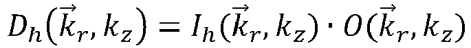
- Each of the detector elements 31 detects a raw image signal from the sample P consisting of the signals D h ( r , z ).
- the raw image signals differ from one another, with the differences are determined by the lateral distance of the illuminating light spot relative to the sample area detected by the respective detector element.
- the function of the evaluation unit C is, from all D h ( r , z ) a picture ⁇ ( r , z ) to reconstruct as closely as possible the original of the sample O ( r , z ) corresponds.
- deconvolution DCV
- subsequent composition of the raw image signals thus developed are used, whereby the processes of development and composition can merge into one another in terms of process technology.
- Fig. 3 all steps are shown in a signal schedule.
- the starting point is the PSFs I h ( r , z ) 40 and the raw image signals D h ( r , z ) 41.
- the PSFs are known due to the properties of the optical system. They can be calculated from system parameters or measured and stored once.
- the signals are forwarded via lines 140, 141 for evaluation 50, which unfolds and assembles all the raw image signals accordingly and an image of the sample ⁇ ( r , z ) 42 which corresponds as closely as possible to the original of the sample O ( r , z ) corresponds.
- the amount of data to be transmitted is represented by the thickness of the arrows 140, 141, 151.
- An image of the sample is obtained from the evaluation ⁇ ( r , z), The amount of data of this image is 32 times less than that of all raw image signals. This is symbolized by the thin arrow 151.
- the factor of the amount of data related to a single image is also indicated by the arrows. So // 32 for the raw image signals and PSFs, // 1 for the image of the sample.
- the area LSM Laser Scanning Microscope
- the area PC describes the control and evaluation device C and thus everything that is required to control the confocal microscope 20, the further processing and display of the data.
- the centerpiece of this area is usually a personal computer C. Specifically, the data of all raw image signals must be transferred from the LSM to the PC will. This requires a powerful interface, or the speed of the data transmission can be limited by a predetermined interface.
- Fig. 4 a more concrete version of the data processing of a confocal microscope 20 is shown with high resolution.
- the evaluation unit 50a performs z. B. a so-called Wiener filtering.
- the raw image signals D h shown in spatial coordinates r , z
- the PSFs I h ( k , k z ) are referred to as the object transfer function OTF.
- w is a real positive number and is referred to here as the Wiener parameter. If the Wiener parameter is small compared to ⁇ h
- x and y correspond to the position of the pixel i :
- D i ⁇ p x ⁇ p y ⁇ e.g. O ⁇ p x , ⁇ p y , e.g. ′ EH i ⁇ p x , ⁇ p y , e.g. ′ dz ′
- Equation (6) transforms the z dimension in the object space into the xy dimension in the measured data.
- the transformation is fully defined by the "confocal" OTF, EH i ( ⁇ p x , ⁇ p y , z ' k ).
- the z dimension in the object space can be reconstructed, for example, by linear regression in the Fourier space.
Description
Die Erfindung bezieht sich auf ein Verfahren zur hochauflösenden 2D-Scanning-Mikroskopie einer Probe, wobei die Probe mit Beleuchtungsstrahlung derart beleuchtet wird, dass die Beleuchtungsstrahlung an einem Punkt in oder auf der Probe zu einem beugungsbegrenzten Beleuchtungsfleck gebündelt wird, wobei eine Beleuchtungs-Punktbildverwaschungsfunktion symmetrisch zur optische Achse ist, der Punkt beugungsbegrenzt in ein Beugungsbild auf einen ortsauflösenden Flächendetektor abgebildet wird, wobei eine Abbildungs-Punktbildverwaschungsfunktion symmetrisch zur optische Achse ist und der Flächendetektor eine Ortsauflösung aufweist, die eine Beugungsstruktur des Beugungsbildes auflöst, der Punkt relativ zur Probe in verschiedene Scanpositionen mit einer Schrittweite verschoben wird, die kleiner ist als der halbe Durchmesser des Beleuchtungsflecks, wobei mehrere Scanpositionen bei einer festen z-Lage einer Fokalebene der Abbildung abgefahren werden, der Flächendetektor ausgelesen und aus den Daten des Flächendetektors und aus den diesen Daten zugeordneten Scanpositionen ein 2D-Bild der Probe erzeugt wird, das eine Auflösung aufweist, die über eine Auflösungsgrenze der Abbildung gesteigert ist.The invention relates to a method for high-resolution 2D scanning microscopy of a sample, the sample being illuminated with illuminating radiation in such a way that the illuminating radiation is focused at a point in or on the sample to form a diffraction-limited illuminating spot, an illuminating point image washing function being symmetrical to the optical axis, the point is imaged diffraction-limited in a diffraction image on a spatially resolving area detector, an imaging point image washing function being symmetrical to the optical axis and the area detector having a spatial resolution which resolves a diffraction structure of the diffraction image, the point relative to the sample in different scan positions is shifted with a step size that is smaller than half the diameter of the illumination spot, several scan positions being traversed at a fixed z position of a focal plane of the image, the area detector is read out and a A 2D image of the sample is generated from the data of the area detector and from the scan positions assigned to this data, which has a resolution that is increased above a resolution limit of the image.
Die Erfindung bezieht sich weiter auf ein Mikroskop zur hochauflösenden 2D-Scanning-Mikroskopie einer Probe, das aufweist einen Beleuchtungsstrahlengang zur Beleuchtung der Probe mit Beleuchtungsstrahlung, wobei die Beleuchtungsstrahlung an einem Punkt in oder auf der Probe zu einem beugungsbegrenzten Beleuchtungsfleck gebündelt ist und eine Beleuchtungs-Punktbildverwaschungsfunktion symmetrisch zur optische Achse ist, einen Abbildungsstrahlengang zur beugungsbegrenzen Abbildung des Punkts in ein Beugungsbild auf einen ortsauflösenden Flächendetektor, wobei eine Abbildungs-Punktbildverwaschungsfunktion symmetrisch zur optische Achse ist und der Flächendetektor eine Ortsauflösung aufweist, die eine Beugungsstruktur des Beugungsbildes auflöst, eine Scaneinrichtung zum Verschieben des Punkts relativ zur Probe in verschiedene Scanpositionen mit einer Schrittweite, die kleiner ist als der halbe Durchmesser des Beleuchtungsflecks, wobei die Scaneinrichtung mehrere Scanpositionen bei einer festen z-Lage einer Fokalebene der Abbildung abfährt, eine Auswerteeinrichtung zum Erzeugen eines 2D-Bildes der Probe aus den Daten des Flächendetektors und aus den diesen Daten zugeordneten Scanpositionen, das eine Auflösung aufweist, die über eine Auflösungsgrenze des Abbildungsstrahlengangs gesteigert ist.The invention further relates to a microscope for high-resolution 2D scanning microscopy of a sample, which has an illuminating beam path for illuminating the specimen with illuminating radiation, the illuminating radiation being focused at a point in or on the specimen to form a diffraction-limited illuminating spot and an illuminating Point image washing function is symmetrical to the optical axis, an imaging beam path for diffraction-limiting imaging of the point in a diffraction image on a spatially resolving area detector, an imaging point image washing function being symmetrical to the optical axis and the area detector having a spatial resolution which resolves a diffraction structure of the diffraction image, a scanning device for shifting of the point relative to the sample in different scan positions with a step size that is smaller than half the diameter of the illumination spot, the scanning device having a plurality of scan positions at e in a fixed z position of a focal plane of the image, an evaluation device for generating a 2D image of the sample from the data of the area detector and from the scan positions associated with this data, which has a resolution that is increased above a resolution limit of the imaging beam path.
Ein klassisches Anwendungsgebiet der Lichtmikroskopie ist die Laser-Scanning-Mikroskope (auch LSM abgekürzt), die mittels einer konfokalen Detektionsanordnung nur diejenige Ebene der Probe abbildet, die sich in der Fokusebene des Objektives befindet. Es wird ein optischer Schnitt gewonnen, dessen Dicke von der Größe der konfokalen Blende abhängt. Die Aufzeichnung mehrerer optischer Schnitte in verschiedenen Tiefen der Probe erlaubt es, ein dreidimensionales Bild der Probe zu generieren, das dann aus den verschiedenen optischen Schnitten zusammengesetzt ist. Die Laser-Scanning-Mikroskopie ist somit zur Untersuchung von dicken Präparaten geeignet.A classic field of application for light microscopy is laser scanning microscope (also abbreviated to LSM), which uses a confocal detection arrangement to image only that plane of the sample that is in the focal plane of the objective. An optical section is obtained, the thickness of which depends on the size of the confocal diaphragm. The recording of several optical sections at different depths of the sample makes it possible to generate a three-dimensional image of the sample, which is then composed of the different optical sections. Laser scanning microscopy is therefore suitable for examining thick specimens.
Prinzipiell ist die optische Auflösung eines Lichtmikroskops, auch die eines LSM, durch die physikalischen Gesetze beugungsbegrenzt. Der Begriff "hochauflösend" wird hier für Auflösungen jenseits der Beugungsgrenze verwendet. Das Überwinden der Beugungsgrenze gelingt der sogenannten Airy-Scan-Mikroskopie, die z. B. in
In der klassischen konfokalen Mikroskopie ist die Tiefenauflösung untrennbar mit der Größe der konfokalen Lochblende verknüpft. Diese Blende filtert außerfokales Licht heraus und lässt den optischen Schnitt entstehen. Damit steigt auf dem Weg zu immer dünneren optischen Schnitten der Lichtverlust, da die Blende signifikant Licht blockt. Die Verwendung einer sehr kleinen konfokalen Blende führt zwar zu einem sehr dünnen optischen Schnitt, jedoch mit sehr schlechtem Signal/Rausch-Verhältnis.In classic confocal microscopy, the depth resolution is inextricably linked to the size of the confocal pinhole. This aperture filters out non-focal light and creates the optical cut. This increases the loss of light on the way to ever thinner optical cuts, since the aperture blocks significant light. The use of a very small confocal aperture leads to a very thin optical section, but with a very poor signal / noise ratio.
Diese Problematik stellt sich auch bei der Airy-Scan-Mikroskopie, die die aus dem klassischen Verfahren (vgl.
Bei der Airy-Scan-Mikroskopie ist eine 3D-Bildaufnahme bekannt, in der sogenannte Bildstapel aufgenommen werden, d. h. mehrere 2D-Bilder in unterschiedlichen Fokalebenen erfasst werden. Diese Bildstapel können dann in einer 3D-Entfaltung für ein tiefenaufgelöstes Bild herangezogen werden. Einen Bildstapel kann man sich sparen, wenn durch eine gezielte Modifikation der Punktbildverwaschungsfunktion die an und für sich gegebene Uneindeutigkeit aufgehoben ist, die darin besteht, dass man a priori nicht weiß, ob ein defokussierter Punkt oberhalb oder unterhalb der Fokalebene liegt. Durch z-modulierte Punktbildverwaschungsfunktionen ist diese Uneindeutigkeit behoben und es lässt sich in einer 3D-Rekonstruktion aus einem einzigen 2D-Bild ein dreidimensionales Bild rekonstruieren.In Airy scan microscopy, 3D image recording is known, in which so-called image stacks are recorded, i.e. H. Multiple 2D images are captured in different focal planes. These image stacks can then be used in 3D for a depth-resolved image. An image stack can be saved if a specific modification of the point image washer function eliminates the inherent ambiguity, which consists in not knowing a priori whether a defocused point is above or below the focal plane. This ambiguity is eliminated by z-modulated point image washing functions and a three-dimensional image can be reconstructed from a single 2D image in a 3D reconstruction.
Dreidimensionalen Bilder erlauben es grundsätzlich, die eingangs geschilderte Problematik der Kopplung zwischen konfokaler Blendengröße und optischer Schnittdicke zu einem gewissen Grade zu beheben. Dazu wird zuerst ein dreidimensionales Bild erzeugt und dann aus dem dreidimensionalen Bild die gewünschte Schnittebene selektiert. Nachteilig ist hierbei, dass ein dreidimensionaler Bildstapel abgearbeitet werden muss oder eine modifizierte Punktbildverwaschungsfunktion verwendet werden muss. Der Erfindung liegt deshalb die Aufgabe zugrunde, die optische Schnittdicke bei der 2D-Airy-Scan-Mikroskopie ohne diese beiden Anforderungen zu verbessern.Three-dimensional images basically make it possible to a certain degree to solve the problem of coupling the confocal aperture size and the optical section thickness described above. To do this, a three-dimensional image is first created and then the desired cutting plane is selected from the three-dimensional image. The disadvantage here is that a three-dimensional image stack must be processed or a modified point image washing function must be used. The invention is therefore based on the object of improving the optical section thickness in 2D Airy scan microscopy without these two requirements.
Die Erfindung ist in den Ansprüchen 1 und 5 definiert.The invention is defined in
Die Erfindung sieht ein Verfahren zur hochaufgelösten Scan-Mikroskopie einer Probe gemäß dem Airy-Scan-Prinzip vor. Die Probe wird mit Beleuchtungsstrahlung beleuchtet. Dabei wird die Beleuchtungsstrahlung an einem Punkt in oder auf der Probe zu einem beugungsbegrenzten Beleuchtungsfleck gebündelt. Dieser Punkt wird beugungsbegrenzt in ein Beugungsbild auf einen Flächendetektor abgebildet. Der Flächendetektor weist Pixel auf und dadurch eine Ortsauflösung, die eine Beugungsstruktur des Beugungsbildes auflöst. Der Punkt wird relativ zur Probe in verschiedene Scanpositionen verschoben. Eine Schrittweite zwischen aufeinanderfolgenden Scanpositionen ist dabei kleiner als der Durchmesser des Beleuchtungsflecks, wodurch jeder Punkt der Probe mehrmals in verschieden liegenden Beleuchtungsflecken und Beugungsbilder enthalten ist. Der Flächendetektor wird ausgelesen. Aus den dabei gewonnen Daten und den diesen Daten zugeordneten Scanpositionen wird ein Bild der Probe erzeugt. Das Bild weist nach dem Airy-Scan-Prinzip eine Auflösung auf, die über eine Auflösungsgrenze der Abbildung hinaus gesteigert ist. Die Beugungsgrenze ist damit überwunden. Es wird ein reiner 2D-Scan durchgeführt.The invention provides a method for high-resolution scan microscopy of a sample according to the Airy scan principle. The sample is illuminated with illuminating radiation. The illuminating radiation is focused at a point in or on the sample to form a diffraction-limited illuminating spot. This point is mapped onto a surface detector in a diffraction pattern with limited diffraction. The area detector has pixels and thereby a spatial resolution which resolves a diffraction structure of the diffraction image. The point is moved to different scan positions relative to the sample. A step size between successive scan positions is smaller than the diameter of the illumination spot, as a result of which each point of the sample is contained several times in differently located illumination spots and diffraction images. The area detector is read out. An image of the sample is generated from the data obtained and the scan positions assigned to this data. According to the Airy scan principle, the image has a resolution that is increased beyond a resolution limit of the image. The diffraction limit is thus overcome. A pure 2D scan is carried out.
Zur Verbesserung der Tiefenauflösung wird aus den Daten des Flächendetektors nicht unmittelbar das 2D-Bild erzeugt, da dann wieder die herkömmliche Verknüpfung zwischen Größe des Beugungsbildes (welche dem Durchmesser der konfokalen Blende entspricht) und der optischen Schnittdicke gegeben wäre. Es wird stattdessen zuerst aus den Daten des Flächendetektors zu den mehreren Scanpositionen eine dreidimensionale Rekonstruktion durchgeführt. Die Daten stammen wegen des reinen 2D-Scans aus der festen z-Lage der Fokalebene. Die dreidimensionale Rekonstruktion ist bekannt, wurde bislang jedoch nur bei Punktbildverwaschungsfunktionen eingesetzt, die gezielt durch ein Manipulationselement im Abbildungs- und/oder Beleuchtungsstrahlengang im bestimmten Maße asymmetrisch gemacht wurden, um die erwähnten Uneindeutigkeiten zu vermeiden. Ein solches Element wird nicht verwendet. Die 3D-Rekonstruktion liefert deshalb nur ein vorläufiges, tiefenaufgelöstes 3D-Bild, da eine einzige Fokalebenenposition ohne Manipulation verwendet wurde. Die Uneindeutigkeitsproblematik besteht, da sowohl die Beleuchtungs-Punktbildverwaschungsfunktion als auch die Abbildungs-Punktbildverwaschungsfunktion nicht gezielt manipuliert wurden und somit im Wesentlichen symmetrisch zur optischen Achse sind (unvermeidbare Rest-Asymmetrien können sich durch unperfekte Bauteile dennoch ergeben - entscheidend ist, dass keine gezielte PSF-Manipulation erfolgt). Diese Uneindeutigkeit wird bewusst hingenommen. Anschließend wird eine reduzierte Schnittdicke festgelegt oder sie war bereits vorbestimmt. Sie ist geringer als die Schnittdicke, die sich aus der optischen Abbildung ergibt. Aus dem vorläufigen tiefenaufgelösten 3D-Bild werden nur diejenigen Anteile selektiert, die innerhalb der reduzierten Schnittdicke um die feste z-Lage der Fokalebene liegen. Anteile, die außerhalb der reduzierten Schnittdicke liegen, werden verworfen. Es handelt sich dabei um die Anteile, die der erwähnten Uneindeutigkeitsproblematik unterliegen.To improve the depth resolution, the 2D image is not generated directly from the data of the area detector, since the conventional link between the size of the diffraction image (which corresponds to the diameter of the confocal diaphragm) and the optical section thickness would then again be provided. Instead, a three-dimensional reconstruction is first carried out from the data of the area detector for the multiple scan positions. Because of the pure 2D scan, the data come from the fixed z position of the focal plane. The three-dimensional reconstruction is known, but has so far been used only for point image washing functions which have been made to a certain extent asymmetrical by a manipulation element in the imaging and / or illumination beam path, in order to avoid the ambiguities mentioned. Such an element is not used. The 3D reconstruction therefore only provides a preliminary, depth-resolved 3D image, since a single focal plane position was used without manipulation. The ambiguity problem exists because both the illumination point image washing function and the image point image washing function have not been manipulated in a targeted manner and are therefore essentially symmetrical to the optical axis (unavoidable residual asymmetries can nevertheless result from imperfect components - the decisive factor is that no targeted PSF Manipulation takes place). This ambiguity is consciously accepted. A reduced section thickness is then specified or it has already been predetermined. It is less than the section thickness that results from the optical image. From the preliminary depth-resolved 3D image, only those parts are selected that lie within the reduced section thickness around the fixed z position of the focal plane. Parts that are outside the reduced section thickness are discarded. These are the parts that are subject to the ambiguity problem mentioned.
Da die Punktbildverwaschungsfunktion nicht modifiziert wird, ist sie im Wesentlichen symmetrisch. Diese Symmetrie ist in der Regel eine Symmetrie zur Fokalebene. In der Regel ist die Punktbildverwaschungsfunktion auch symmetrisch zur optischen Achse, insbesondere ist sie rotationssymmetrisch. Bei den meisten Mikroskopen entspricht die Punktbildverwaschungsfunktion einer Sanduhr-artigen Form, wobei die Taille in der Fokalebene liegt. Etwaige verbleibende Unsymmetrien, die sich durch die reale Verwirklichung der abbildenden Elemente ergibt, führen nicht zu einer derartigen Modifikation, dass die dreidimensionale Rekonstruktion aus einem einzigen Bild ein tiefenaufgelöstes Bild ohne Eindeutigkeiten ergäbe. Es werden zur 3D-Rekonstruktion aus den Bilddaten, die für eine feste Lage der Fokalebene und mit der unmodifizierten Punktbildverwaschungsfunktion erhalten wurden, bekannte Rekonstruktionsalgorithmen verwendet. Sie wurde zur Erzeugung eines tiefenaufgelösten 3D-Bildes für Mikroskope mit gezielter Manipulation der Punktbildverwaschungsfunktion entwickelt. Damit wird ein 3D-Bild erhalten, das tiefenaufgelöst ist, jedoch aufgrund der Uneindeutigkeiten dieses Bild kein vollwertiges und artefaktfreies 3D-Bild ist. Es wird deshalb hier als vorläufiges tiefenaufgelöstes 3D-Bild bezeichnet, um es von tiefenaufgelösten 3D-Bildern zu unterscheiden, die man bei gezielter und umfangreicher Manipulation der Punktbildverwaschungsfunktion mit denselben Rekonstruktionsalgorithmen erhalten würden und die artefaktfrei wären.Since the point spread function is not modified, it is essentially symmetrical. This symmetry is usually symmetry to the focal plane. As a rule, the point image washing function is also symmetrical to the optical axis, in particular it is rotationally symmetrical. This corresponds to most microscopes Point spreading function of an hourglass-like shape, with the waist lying in the focal plane. Any remaining asymmetries that result from the real realization of the imaging elements do not lead to such a modification that the three-dimensional reconstruction from a single image would result in a depth-resolved image without ambiguities. Known reconstruction algorithms are used for the 3D reconstruction from the image data which were obtained for a fixed position of the focal plane and with the unmodified point image washing function. It was developed for the generation of a deeply resolved 3D image for microscopes with targeted manipulation of the point image washing function. This results in a 3D image that is depth-resolved, but because of the ambiguities this image is not a full-fledged and artifact-free 3D image. It is therefore referred to here as a preliminary depth-resolved 3D image in order to distinguish it from depth-resolved 3D images that would be obtained with targeted and extensive manipulation of the point image washing function with the same reconstruction algorithms and that would be artifact-free.
Der Strahlengang der Abbildung und Beleuchtung ist frei von Elemente, die eine Punktbildverwaschungsfunktion manipulieren und einen gezielten, bestimmbaren Grad der Asymmetrie einführen, welcher für die tiefenaufgelösten Ansätze, wie sie beispielsweise in der Publikation von Jesacher et al. erläutert sind, notwendig und verwendet sind. Insbesondere finden sich im Strahlengang keine astigmatischen Linsen oder Phasenmasken, welche die Punktbildverwaschungsfunktion asymmetrisch und tiefenabhängig auf bestimmte Weise gezielt modulieren.The beam path of the imaging and lighting is free of elements that manipulate a point image washing function and introduce a specific, determinable degree of asymmetry, which is necessary for the depth-resolved approaches, as described, for example, in the publication by Jesacher et al. are explained, necessary and used. In particular, there are no astigmatic lenses or phase masks in the beam path, which modulate the point image washing function asymmetrically and depth-dependent in a specific way.
Die dreidimensionale Rekonstruktion erzeugt in einer Ausführungsform 3D-Bilder in mehreren diskreten Schnittebenen. Es ist deshalb in einer Weiterbildung bevorzugt, das vorläufige, tiefenaufgelöste 3D-Bild so zu erzeugen, dass es mehrere diskrete Schnittebenen enthält. Als selektierter Anteil wird dann diejenige Schnittebene ausgewählt, die der festen z-Lage der Fokalebene entspricht.In one embodiment, the three-dimensional reconstruction generates 3D images in several discrete cutting planes. It is therefore preferred in a further development to generate the preliminary, depth-resolved 3D image in such a way that it contains several discrete cutting planes. The section plane that corresponds to the fixed z position of the focal plane is then selected as the selected component.
Mit der Beleuchtungsstrahlung kann die Abgabe von Fluoreszenzstrahlung angeregt werden, was das Signal/Rausch-Verhältnis verbessert und den Algorithmus insgesamt stärkt, insbesondere kann die reduzierte Schnittdicke dann sehr dünn sein.The emission of fluorescent radiation can be stimulated with the illuminating radiation, which improves the signal / noise ratio and strengthens the algorithm as a whole, in particular the reduced slice thickness can then be very thin.
Das analog zum Verfahren vorgesehen Mikroskop hat eine Auswerteeinrichtung, welche die Verfahrensschritte durchführt und dazu geeignet ausgebildet ist. Analog zum Verfahren ist ein entsprechendes Mikroskop vorgesehen, das einen Beleuchtungsstrahlengang zur Beleuchtung der Probe mit den genannten Eigenschaften und einen Abbildungsstrahlengang zur beugungsbegrenzten Abbildung des Punkts in ein Beugungsbild auf den Flächendetektor mit seinen Pixeln umfasst. Wie bereits erwähnt, erhält der Beleuchtungsstrahlengang und der Abbildungsstrahlengang kein Manipulationselement, um die Punktbildverwaschungsfunktion asymmetrisch zu machen; insbesondere sind keine astigmatischen Linsen oder Phasenmasken vorgesehen. Der Begriff der Manipulation stellt dabei auf eine gezielte Beeinflussung der Punktbildverwaschungsfunktion ab, mit der eine Asymmetrie erzeugt wird, welche insbesondere bei der 3D-Rekonstruktion eine Uneindeutigkeit zwischen Schichten, die unterhalb der Fokalebene liegen, und Schichten, die oberhalb der Fokalebene liegen, vermeidet. Eine Manipulation ist also gleichbedeutend damit, dass Schichten unterhalb der Fokalebene eine eindeutig andere Punktbildverwaschungsfunktion haben, als Schichten, die oberhalb der Fokalebene liegen. Eine solche Manipulation erfordert üblicherweise den Einsatz von Phasenmasken und/oder astigmatischen Elementen im Strahlengang.The microscope provided analogously to the method has an evaluation device which carries out the method steps and is suitably designed for this. Analogous to the method, a corresponding microscope is provided, which includes an illumination beam path for illuminating the sample with the properties mentioned and an imaging beam path for diffraction-limited imaging of the point in a diffraction image on the surface detector its pixels. As already mentioned, the illuminating beam path and the imaging beam path are not provided with a manipulation element in order to make the point image washing function asymmetrical; in particular, no astigmatic lenses or phase masks are provided. The term manipulation is aimed at influencing the point image washing function in a targeted manner, with which an asymmetry is generated which, in particular in the case of 3D reconstruction, avoids ambiguity between layers which lie below the focal plane and layers which lie above the focal plane. Manipulation is therefore synonymous with the fact that layers below the focal plane have a clearly different point spread function than layers lying above the focal plane. Such manipulation usually requires the use of phase masks and / or astigmatic elements in the beam path.
Soweit nachfolgend Aspekte des Verfahrens zur Mikroskopie erläutert werden, betreffen diese Aspekte gleichermaßen die Auswerteeinrichtung, die geeignet ausgebildet ist, die entsprechenden Verfahrensschritte auszuführen. Es kann sich dabei um einen Computer handeln, der mit entsprechender Software oder mit entsprechendem Programmcode ausgestaltet ist. Umgekehrt betreffen Aspekte, die anhand des Mikroskops und dessen Arbeitsweise geschildert werden, gleichermaßen das Verfahren zur Mikroskopie.Insofar as aspects of the method for microscopy are explained below, these aspects equally relate to the evaluation device, which is designed to carry out the corresponding method steps. It can be a computer that is designed with the appropriate software or with the appropriate program code. Conversely, aspects that are described on the basis of the microscope and its mode of operation equally affect the method for microscopy.
Es versteht sich, dass die vorstehend genannten und die nachstehend noch zu erläuternden Merkmale nicht nur in den angegebenen Kombinationen, sondern auch in anderen Kombinationen oder in Alleinstellung einsetzbar sind, ohne den Rahmen der vorliegenden Erfindung zu verlassen.It goes without saying that the features mentioned above and those yet to be explained below can be used not only in the specified combinations but also in other combinations or on their own without departing from the scope of the present invention.
Nachfolgend wird die Erfindung anhand von Ausführungsbeispielen unter Bezugnahme auf die beigefügten Zeichnungen, die ebenfalls erfindungswesentliche Merkmale offenbaren, noch näher erläutert. Diese Ausführungsbeispiele dienen lediglich der Veranschaulichung und sind nicht als einschränkend auszulegen. Beispielsweise ist eine Beschreibung eines Ausführungsbeispiels mit einer Vielzahl von Elementen oder Komponenten nicht dahingehend auszulegen, dass alle diese Elemente oder Komponenten zur Implementierung notwendig sind. Vielmehr können andere Ausführungsbeispiele auch alternative Elemente und Komponenten, weniger Elemente oder Komponenten oder zusätzliche Elemente oder Komponenten enthalten. Elemente oder Komponenten verschiedener Ausführungsbespiele können miteinander kombiniert werden, sofern nichts anderes angegeben ist. Modifikationen und Abwandlungen, welche für eines der Ausführungsbeispiele beschrieben werden, können auch auf andere Ausführungsbeispiele anwendbar sein. Zur Vermeidung von Wiederholungen werden gleiche oder einander entsprechende Elemente in verschiedenen Figuren mit gleichen Bezugszeichen bezeichnet und nicht mehrmals erläutert. Von den Figuren zeigen:
- Fig. 1
- eine Schemadarstellung eines Mikroskops zur hochauflösenden Mikroskopie,
- Fig. 2, 2a und 2b
- Schemadarstellungen der Anordnungen von Pixeln eines Detektors des Mikroskops der
Fig. 1 , - Fig. 3
- einen Signallaufplan zum Mikroskopieverfahren, und
- Fig. 4
- ein Ausführungsbeispiel für die Datenverarbeitung eines hochauflösenden Konfokalmikroskops.
- Fig. 1
- a schematic representation of a microscope for high-resolution microscopy,
- 2, 2a and 2b
- Schematic representation of the arrangement of pixels of a detector of the microscope
Fig. 1 , - Fig. 3
- a signal schedule for the microscopy method, and
- Fig. 4
- an embodiment for the data processing of a high-resolution confocal microscope.
Das von der Probe im Beleuchtungsfleck B erzeugte Probenlicht D wird vom Objektiv 13 gesammelt und über umgekehrten Weg wie das Beleuchtungslicht B zum Strahlteiler 9 geleitet. Der Strahlteiler 9 ist so gestaltet, dass er einen möglichst großen Anteil des Probenlichts D transmittiert. Das so vom Strahlteiler 9 transmittierte Probenlicht D wird über einen weiteren Filter 15 und eine weitere Strahlformungsoptik 16 zum Detektor 17 geleitet. Der Detektor 17 detektiert das Probenlicht D, erzeugt daraus elektrische Signale und leitet diese über Leiter 23, 24, 25 an eine Steuer- und Auswerteeinrichtung C, z. B. einen Computer, weiter. Auf diese Weise wird ein Beugungsbild 18 aufgenommen, das, wie die Beugungsstruktur 18a zeigt, beugungsbegrenzt ist.The sample light D generated by the sample in the illumination spot B is collected by the
Um ein Bild von der Probe P zu erhalten, wird der Beleuchtungsfleck 14 mit dem Scanner 10 punktweise über die Probe P bewegt. Aus den so gewonnenen punktweisen Probensignalen wird von der Steuer- und Auswerteeinrichtung C ein 3D-Bild zusammengesetzt, welches z. B. mittels eines Monitors dargestellt werden kann.In order to obtain an image of the sample P, the
Der Scanner 10 erlaubt es dabei, ein zweidimensionales Bild aufzunehmen, welches sich lateral, also in einer Ebene senkrecht zur optischen Achse des Objektivs erstreckt.The
Wie bereits erwähnt, erhält der Beleuchtungsstrahlengang und der Abbildungsstrahlengang kein Manipulationselement, um die Punktbildverwaschungsfunktion gezielt asymmetrisch zu machen; insbesondere sind keine astigmatischen Linsen oder Phasenmasken vorgesehen. Der Begriff der Manipulation stellt dabei auf eine gezielte Beeinflussung der Punktbildverwaschungsfunktion ab, mit der eine Asymmetrie erzeugt wird, welche insbesondere bei der 3D-Rekonstruktion eine Uneindeutigkeit zwischen Schichten, die unterhalb der Fokalebene liegen, und Schichten, die oberhalb der Fokalebene liegen, vermeidet. Eine gezielte Manipulation ist also gleichbedeutend damit, dass Schichten unterhalb der Fokalebene eine eindeutig andere Punktbildverwaschungsfunktion haben, als Schichten, die oberhalb der Fokalebene liegen. Eine solche Manipulation erfordert üblicherweise den Einsatz von Phasenmasken und/oder astigmatischen Elementen im Strahlengang.As already mentioned, the illuminating beam path and the imaging beam path do not receive any manipulation element in order to specifically asymmetrically increase the point image washing function do; in particular, no astigmatic lenses or phase masks are provided. The term manipulation is aimed at influencing the point image washing function in a targeted manner, with which an asymmetry is generated which, in particular in the case of 3D reconstruction, avoids ambiguity between layers which lie below the focal plane and layers which lie above the focal plane. Targeted manipulation is therefore synonymous with the fact that layers below the focal plane have a clearly different point spread function than layers that lie above the focal plane. Such manipulation usually requires the use of phase masks and / or astigmatic elements in the beam path.
In
Die Größe der Pixel 31 ist so gewählt, dass sie wesentlich kleiner als das auf dem Detektor 17 erzeugte Beugungsbild 18 sind. Gleichzeitig ist die Anzahl der Pixel 31 und damit die gesamte Fläche des Detektors 17 so gewählt, dass ein wesentlicher Anteil des Probenlichts D für das Beugungsbild 18 detektiert werden kann.The size of the
Zum Vergleich ist in
Der Detektor 17 des Konfokalmikroskops 20 mit hoher Auflösung erfasst für jeden abgetasteten Punkt P(
Jedes der Detektorelemente 31 erfasst ein Rohbildsignal von der Probe P bestehend aus den Signalen Dh ( ![]()
![]()
Die Funktion der Auswerteeinheit C ist es, aus allen Dh (
In
In
Mit der gestrichelten Linie 60 sind Bereiche des gesamten konfokalen Mikroskops 20 voneinander abgegrenzt, zwischen denen die Daten der Rohbildsignale übertragen werden müssen. Dabei umfasst der Bereich LSM (Laser Scanning Microscope) hardwarenahe Bereiche des Konfokalmikroskops, also Optik, Mechanik und Elektronik, welche eine Datenübertragung zum Bereich PC ermöglicht. Der Bereich PC beschreibt die Steuer- und Auswerteeinrichtung C und damit alles, was zur Steuerung des Konfokalmikroskops 20, der weiteren Verarbeitung und Darstellung der Daten erforderlich ist. Kernstück dieses Bereichs ist üblicherweise ein Personal Computer C. Konkret müssen die Daten aller Rohbildsignale vom LSM zum PC übertragen werden. Dazu ist eine leistungsfähige Schnittstelle erforderlich, bzw. die Geschwindigkeit der Datenübertragung kann durch eine vorgegebene Schnittstelle limitiert sein.Areas of the entire
In
Für das Verständnis der Entfaltungsformel in 50a sind zwei Punkte wichtig:
- 1. Die Rohbildsignale entsprechen der Probe gefaltet mit der System-PSF; wie oben bereits dargestellt:
- 2. Eine Faltung im Ortsraum entspricht einer Multiplikation im Fourierraum. D. h. im Fourierraum lassen sich die Rohbildsignale als Produkt aus Probe und OTF darstellen:
- 1. The raw image signals correspond to the sample folded with the system PSF; as already shown above:
- 2. A convolution in the space corresponds to a multiplication in the Fourier space. That is, In the Fourier room, the raw image signals can be represented as a product of the sample and OTF:
Setzt man die Formel für Dh ( 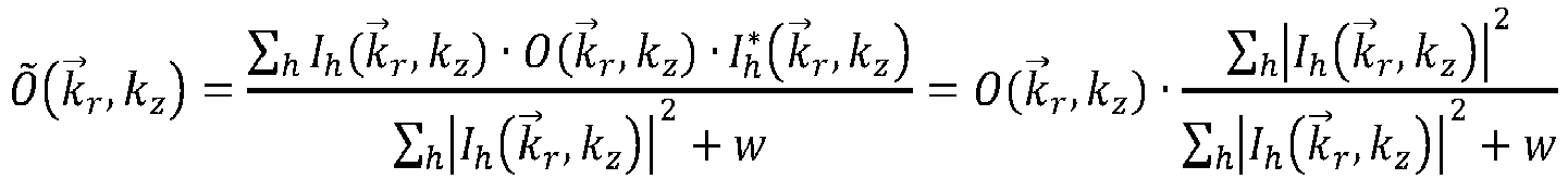
![]()
![]()
w ist eine reelle positive Zahl und sei hier als Wiener-Parameter bezeichnet. Ist der Wiener-Parameter klein gegenüber ∑ h |Ih (
Um das Bild darstellen zu können, muss das in Raumfrequenzkoordinaten vorliegende Bild Õ(
Das detektierte Signal, D( 
Aus (1) in 2D Fall (pz = 0, z = 0) ergibt sich als dreidimensionale Gleichung: 
Die Fourier-Transformation von (2) in px und py ergibt 
Substitution von FTx',y' {E(x',y',z')H(x+x',y+y',z')} durch EH(x,y,ωp
Zur Vereinfachung der Notation wird angenommen, dass x und y der Position des Pixels i entspricht: 
Diskretisieren des Integrals über z in (5) führt zu 
Gleichung (6) transformiert die z-Dimension im Objektraum in die x-y-Dimension in den gemessenen Daten. Die Transformation ist vollständig definiert durch die "confocal" OTF, EHi(ω
Da wegen der unmanipulierten, insbesondere symmetrischen Punktbildverwaschungsfunktion eine eindeutige Lösung nach dieser dreidimensionalen Rekonstruktion nur für die Fokalebene vorliegt, kann diese unproblematisch ausgewählt werden. Die außerfokalen Ebenen werden verworfen, d. h. Ebenen, die außerhalb der vorbestimmten Schnittdicke und insbesondere oberhalb und unterhalb der Fokusebene liegen. Sie wären ohnehin nicht eindeutig zuzuordnen. Dies ist jedoch unproblematisch, da die vorliegende Mikroskopie ein 2D-Bild erzeugt. Es wird deshalb nach einer linearen Regressionsanalyse im Fourierraum das zentrale Bild des erhaltenen z-Stapels ausgewählt. Dies entspricht folgender Gleichung: 
Claims (8)
- Method for high-resolution 2D scanning microscopy of a sample (P), wherein- the sample (P) is illuminated with illumination radiation in such a way that the illumination radiation (B) is focused at a point in or on the sample (P) to form a diffraction-limited illumination spot (14), wherein- the point is imaged in a diffraction-limited manner into a diffraction image (18) on a spatially resolving surface detector (17), and the surface detector (17) has a spatial resolution that resolves a diffraction structure (18a) of the diffraction image (18),- wherein manipulated is neither an imaging point spread function nor an illumination point spread function for producing an asymmetry,- the point is displaced relative to the sample (P) into different scanning positions with an increment of less than half the diameter of the illumination spot (14), wherein a plurality of scanning positions are traveled with a fixed z-location of a focal plane of the imaging,- the surface detector (17) is read, and a 2D image of the sample (P) is produced from the data of the surface detector (17) and from the scanning positions assigned to said data, said 2D image having a resolution that is increased beyond a resolution limit for imaging,characterized in that- the data of the surface detector (17) with respect to the plurality of scanning positions at the fixed z-location of the focal plane are used to perform a three-dimensional reconstruction which provides a provisional depth-resolved 3D image,- a reduced section thickness is specified or predetermined, which is less than a section thickness which is produced by the imaging,- in the provisional, depth-resolved 3D image, only portions which are situated in the reduced section thickness around the fixed z-location of the focal plane are selected, and portions which are outside the reduced section thickness around the fixed z-location of the focal plane are discarded to produce the 2D image.
- Method according to Claim 1, characterized in that in the three-dimensional deconvolution the provisional, depth-resolved 3D image is produced such that it contains a plurality of discrete section planes, and in that, as a selected portion, the section plane which is assigned to, or closest to, the fixed z-location of the focal plane is used.
- Method according to Claim 1 or 2, characterized in that the imaging point spread function and the illumination point spread function are symmetric with respect to the optical axis.
- Method according to Claim 1, 2 or 3, characterized in that the sample (P) is excited with the illumination radiation (B) to emit fluorescence radiation.
- Microscope for high-resolution 2D scanning microscopy of a sample (P), comprising- an illumination beam path for illuminating the sample (P) with illumination radiation (B), wherein the illumination radiation is focused at a point in or on the sample (P) to form a diffraction-limited illumination spot (14), wherein the illumination beam path is free from elements for manipulating an illumination point spread function,- an imaging beam path for the diffraction-limited imaging of the point into a diffraction image (18) on a spatially resolving surface detector (17), wherein the imaging beam path is free from elements for manipulating an imaging point spread function and the surface detector (17) has a spatial resolution that resolves a diffraction structure (18a) of the diffraction image (18),- a scanning device (10) for displacing the point relative to the sample (P) into different scanning positions with an increment of less than half the diameter of the illumination spot (14), wherein the scanning device travels a plurality of scanning positions with a fixed z-location of a focal plane of the image,- an evaluation device (C) for producing a 2D image of the sample (P) from the data of the surface detector (17) and from the scanning positions assigned to said data, said 2D image having a resolution that is increased beyond a resolution limit of the imaging beam path,characterized in that- the evaluation device (C) performs a three-dimensional deconvolution and produces a provisional depth-resolved 3D image with the data of the surface detector (17) with respect to the plurality of scanning positions at the fixed z-location of the focal plane,- the evaluation device (C) specifies a reduced section thickness a reduced section thickness, or a reduced section thickness is predetermined for the evaluation device, which is less than a section thickness which is produced by the imaging,- the evaluation device (C) selects in the provisional, depth-resolved 3D image only portions which are situated in the reduced section thickness around the fixed z-location of the focal plane, and discards portions which are outside the reduced section thickness around the fixed z-location of the focal plane to produce the 2D image.
- Microscope according to Claim 5, characterized in that the evaluation device (C) produces the provisional, depth-resolved 3D image in the three-dimensional deconvolution such that it contains a plurality of discrete section planes, and uses, as a selected portion, the section plane which is assigned to, or closest to, the fixed z-location of the focal plane.
- Microscope according to Claim 5 or 6, characterized in that the imaging point spread function and the illumination point spread function are symmetric with respect to the optical axis.
- Microscope according to Claim 5, 6 or 7, characterized in that the illumination radiation beam excites the sample (P) to emit fluorescence radiation.
Applications Claiming Priority (1)
| Application Number | Priority Date | Filing Date | Title |
|---|---|---|---|
| DE102017119531.9A DE102017119531A1 (en) | 2017-08-25 | 2017-08-25 | High-resolution 2D microscopy with improved slice thickness |
Publications (2)
| Publication Number | Publication Date |
|---|---|
| EP3447559A1 EP3447559A1 (en) | 2019-02-27 |
| EP3447559B1 true EP3447559B1 (en) | 2020-04-08 |
Family
ID=63294071
Family Applications (1)
| Application Number | Title | Priority Date | Filing Date |
|---|---|---|---|
| EP18189298.5A Active EP3447559B1 (en) | 2017-08-25 | 2018-08-16 | High resolution 2d microscopy with improved cut thickness |
Country Status (5)
| Country | Link |
|---|---|
| US (1) | US10996452B2 (en) |
| EP (1) | EP3447559B1 (en) |
| JP (1) | JP7190843B2 (en) |
| CN (1) | CN109425978B (en) |
| DE (1) | DE102017119531A1 (en) |
Families Citing this family (6)
| Publication number | Priority date | Publication date | Assignee | Title |
|---|---|---|---|---|
| DE102019100184A1 (en) | 2019-01-07 | 2020-07-09 | Carl Zeiss Microscopy Gmbh | High resolution scanning microscopy |
| DE102019107267A1 (en) * | 2019-03-21 | 2020-09-24 | Carl Zeiss Microscopy Gmbh | Process for high-resolution scanning microscopy |
| DE102019007066A1 (en) * | 2019-10-11 | 2021-04-15 | Abberior Instruments Gmbh | Method and device for correcting aberrations in fluorescence microscopy |
| MX2022004773A (en) * | 2019-10-21 | 2022-05-16 | Illumina Inc | Systems and methods for structured illumination microscopy. |
| DE102020122605A1 (en) | 2020-08-28 | 2022-03-03 | Abberior Instruments Gmbh | Method, image processing unit and laser scanning microscope for background-reduced imaging of a structure in a sample |
| CN115598822B (en) * | 2022-12-15 | 2023-03-10 | 达州爱迦飞诗特科技有限公司 | Intelligent multi-dimensional microscopic image acquisition and processing method |
Family Cites Families (11)
| Publication number | Priority date | Publication date | Assignee | Title |
|---|---|---|---|---|
| US3013467A (en) | 1957-11-07 | 1961-12-19 | Minsky Marvin | Microscopy apparatus |
| US6166853A (en) * | 1997-01-09 | 2000-12-26 | The University Of Connecticut | Method and apparatus for three-dimensional deconvolution of optical microscope images |
| US7197193B2 (en) | 2002-05-03 | 2007-03-27 | Creatv Microtech, Inc. | Apparatus and method for three dimensional image reconstruction |
| US20090219607A1 (en) * | 2008-01-17 | 2009-09-03 | Baylor College Of Medicine | Method and apparatus for enhanced resolution microscopy of living biological nanostructures |
| EP3667391A1 (en) | 2009-10-28 | 2020-06-17 | Carl Zeiss Microscopy GmbH | Microscopic method and microscope with improved resolution |
| EP2557584A1 (en) * | 2011-08-10 | 2013-02-13 | Fei Company | Charged-particle microscopy imaging method |
| DE102013019347A1 (en) * | 2013-08-15 | 2015-02-19 | Carl Zeiss Microscopy Gmbh | High-resolution scanning microscopy |
| DE102013015933A1 (en) | 2013-09-19 | 2015-03-19 | Carl Zeiss Microscopy Gmbh | High-resolution scanning microscopy |
| DE102013218795A1 (en) * | 2013-09-19 | 2015-03-19 | Carl Zeiss Microscopy Gmbh | Laser scanning microscope and method for correcting aberrations, in particular in high-resolution scanning microscopy |
| DE102015111702A1 (en) | 2015-07-20 | 2017-01-26 | Carl Zeiss Microscopy Gmbh | High-resolution, spectrally selective scanning microscopy of a sample |
| CN105319196B (en) * | 2015-11-30 | 2019-02-05 | 哈尔滨工业大学 | A kind of super-resolution structure detection confocal fluorescent imaging device and its imaging method |
-
2017
- 2017-08-25 DE DE102017119531.9A patent/DE102017119531A1/en active Pending
-
2018
- 2018-08-16 EP EP18189298.5A patent/EP3447559B1/en active Active
- 2018-08-22 JP JP2018155090A patent/JP7190843B2/en active Active
- 2018-08-27 CN CN201810979516.3A patent/CN109425978B/en active Active
- 2018-09-13 US US16/107,506 patent/US10996452B2/en active Active
Non-Patent Citations (1)
| Title |
|---|
| None * |
Also Published As
| Publication number | Publication date |
|---|---|
| JP7190843B2 (en) | 2022-12-16 |
| US20190064495A1 (en) | 2019-02-28 |
| DE102017119531A1 (en) | 2019-02-28 |
| EP3447559A1 (en) | 2019-02-27 |
| US10996452B2 (en) | 2021-05-04 |
| JP2019040185A (en) | 2019-03-14 |
| CN109425978A (en) | 2019-03-05 |
| CN109425978B (en) | 2022-05-24 |
Similar Documents
| Publication | Publication Date | Title |
|---|---|---|
| EP3447559B1 (en) | High resolution 2d microscopy with improved cut thickness | |
| EP1248132B1 (en) | Method and arrangement for depth resolving optical detection of a probe | |
| EP2917776B1 (en) | Optical microscope and microscopy method | |
| EP1943625B1 (en) | Image processing method and device | |
| EP1862839B1 (en) | Microscope with improved resolution | |
| EP3650905B1 (en) | Improved method and devices for microscopy with structured illumination | |
| EP3692409B1 (en) | High-resolution confocal microscope | |
| EP3304165B1 (en) | Assembly and method for beam shaping and for light sheet microscopy | |
| DE102007018048A1 (en) | Method and arrangement for optical imaging with depth discrimination | |
| WO2000052512A1 (en) | Method and device for representing an object | |
| DE102020211380A1 (en) | Process for super-resolution evaluation of structured illuminated microscope images and microscope with structured illumination | |
| EP2718762A1 (en) | High-resolution luminescence microscopy | |
| WO2013053859A1 (en) | High-resolution luminescence microscopy | |
| EP3655810B1 (en) | Light sheet microscopy method for generating a volume image of a sample, and light sheet microscope | |
| DE10155002A1 (en) | Depth-resolved optical imaging method for use in biological scanning microscopy, uses phase or frequency modulation of the imaging light | |
| DE102020122605A1 (en) | Method, image processing unit and laser scanning microscope for background-reduced imaging of a structure in a sample | |
| EP3712670A1 (en) | Method for high-resolution scanning microscopy | |
| DE10118463A1 (en) | Depth-resolved optical imaging method for use in biological scanning microscopy, uses phase or frequency modulation of the imaging light | |
| DE102015116598A1 (en) | Method and microscope for high-resolution imaging by means of SIM | |
| DE102019100184A1 (en) | High resolution scanning microscopy | |
| WO2016071033A1 (en) | Method for generating an image of a sample | |
| DE102019132384A1 (en) | Method for creating a high-resolution image, data processing system and optical observation device | |
| EP3341781B1 (en) | Illumination arrangement for a light sheet microscope | |
| EP3198323B1 (en) | Device for imaging a sample | |
| DE102021123130A1 (en) | DEVICE AND METHOD FOR LIGHT FIELD MICROSCOPY |
Legal Events
| Date | Code | Title | Description |
|---|---|---|---|
| PUAI | Public reference made under article 153(3) epc to a published international application that has entered the european phase |
Free format text: ORIGINAL CODE: 0009012 |
|
| STAA | Information on the status of an ep patent application or granted ep patent |
Free format text: STATUS: THE APPLICATION HAS BEEN PUBLISHED |
|
| AK | Designated contracting states |
Kind code of ref document: A1 Designated state(s): AL AT BE BG CH CY CZ DE DK EE ES FI FR GB GR HR HU IE IS IT LI LT LU LV MC MK MT NL NO PL PT RO RS SE SI SK SM TR |
|
| AX | Request for extension of the european patent |
Extension state: BA ME |
|
| STAA | Information on the status of an ep patent application or granted ep patent |
Free format text: STATUS: REQUEST FOR EXAMINATION WAS MADE |
|
| 17P | Request for examination filed |
Effective date: 20190709 |
|
| RBV | Designated contracting states (corrected) |
Designated state(s): AL AT BE BG CH CY CZ DE DK EE ES FI FR GB GR HR HU IE IS IT LI LT LU LV MC MK MT NL NO PL PT RO RS SE SI SK SM TR |
|
| GRAP | Despatch of communication of intention to grant a patent |
Free format text: ORIGINAL CODE: EPIDOSNIGR1 |
|
| STAA | Information on the status of an ep patent application or granted ep patent |
Free format text: STATUS: GRANT OF PATENT IS INTENDED |
|
| INTG | Intention to grant announced |
Effective date: 20191114 |
|
| RIN1 | Information on inventor provided before grant (corrected) |
Inventor name: KLEPPE, INGO Inventor name: NOVIKAU, YAUHENI |
|
| GRAS | Grant fee paid |
Free format text: ORIGINAL CODE: EPIDOSNIGR3 |
|
| GRAA | (expected) grant |
Free format text: ORIGINAL CODE: 0009210 |
|
| STAA | Information on the status of an ep patent application or granted ep patent |
Free format text: STATUS: THE PATENT HAS BEEN GRANTED |
|
| AK | Designated contracting states |
Kind code of ref document: B1 Designated state(s): AL AT BE BG CH CY CZ DE DK EE ES FI FR GB GR HR HU IE IS IT LI LT LU LV MC MK MT NL NO PL PT RO RS SE SI SK SM TR |
|
| REG | Reference to a national code |
Ref country code: AT Ref legal event code: REF Ref document number: 1255168 Country of ref document: AT Kind code of ref document: T Effective date: 20200415 Ref country code: CH Ref legal event code: EP |
|
| REG | Reference to a national code |
Ref country code: DE Ref legal event code: R096 Ref document number: 502018001144 Country of ref document: DE |
|
| REG | Reference to a national code |
Ref country code: IE Ref legal event code: FG4D Free format text: LANGUAGE OF EP DOCUMENT: GERMAN |
|
| REG | Reference to a national code |
Ref country code: CH Ref legal event code: PK Free format text: BERICHTIGUNGEN |
|
| RIN2 | Information on inventor provided after grant (corrected) |
Inventor name: NOVIKAU, YAUHENI Inventor name: KLEPPE, INGO |
|
| REG | Reference to a national code |
Ref country code: NL Ref legal event code: FP |
|
| REG | Reference to a national code |
Ref country code: DE Ref legal event code: R083 Ref document number: 502018001144 Country of ref document: DE |
|
| REG | Reference to a national code |
Ref country code: LT Ref legal event code: MG4D |
|
| PG25 | Lapsed in a contracting state [announced via postgrant information from national office to epo] |
Ref country code: LT Free format text: LAPSE BECAUSE OF FAILURE TO SUBMIT A TRANSLATION OF THE DESCRIPTION OR TO PAY THE FEE WITHIN THE PRESCRIBED TIME-LIMIT Effective date: 20200408 Ref country code: GR Free format text: LAPSE BECAUSE OF FAILURE TO SUBMIT A TRANSLATION OF THE DESCRIPTION OR TO PAY THE FEE WITHIN THE PRESCRIBED TIME-LIMIT Effective date: 20200709 Ref country code: NO Free format text: LAPSE BECAUSE OF FAILURE TO SUBMIT A TRANSLATION OF THE DESCRIPTION OR TO PAY THE FEE WITHIN THE PRESCRIBED TIME-LIMIT Effective date: 20200708 Ref country code: IS Free format text: LAPSE BECAUSE OF FAILURE TO SUBMIT A TRANSLATION OF THE DESCRIPTION OR TO PAY THE FEE WITHIN THE PRESCRIBED TIME-LIMIT Effective date: 20200808 Ref country code: PT Free format text: LAPSE BECAUSE OF FAILURE TO SUBMIT A TRANSLATION OF THE DESCRIPTION OR TO PAY THE FEE WITHIN THE PRESCRIBED TIME-LIMIT Effective date: 20200817 Ref country code: FI Free format text: LAPSE BECAUSE OF FAILURE TO SUBMIT A TRANSLATION OF THE DESCRIPTION OR TO PAY THE FEE WITHIN THE PRESCRIBED TIME-LIMIT Effective date: 20200408 Ref country code: SE Free format text: LAPSE BECAUSE OF FAILURE TO SUBMIT A TRANSLATION OF THE DESCRIPTION OR TO PAY THE FEE WITHIN THE PRESCRIBED TIME-LIMIT Effective date: 20200408 |
|
| PG25 | Lapsed in a contracting state [announced via postgrant information from national office to epo] |
Ref country code: HR Free format text: LAPSE BECAUSE OF FAILURE TO SUBMIT A TRANSLATION OF THE DESCRIPTION OR TO PAY THE FEE WITHIN THE PRESCRIBED TIME-LIMIT Effective date: 20200408 Ref country code: BG Free format text: LAPSE BECAUSE OF FAILURE TO SUBMIT A TRANSLATION OF THE DESCRIPTION OR TO PAY THE FEE WITHIN THE PRESCRIBED TIME-LIMIT Effective date: 20200708 Ref country code: RS Free format text: LAPSE BECAUSE OF FAILURE TO SUBMIT A TRANSLATION OF THE DESCRIPTION OR TO PAY THE FEE WITHIN THE PRESCRIBED TIME-LIMIT Effective date: 20200408 Ref country code: LV Free format text: LAPSE BECAUSE OF FAILURE TO SUBMIT A TRANSLATION OF THE DESCRIPTION OR TO PAY THE FEE WITHIN THE PRESCRIBED TIME-LIMIT Effective date: 20200408 |
|
| PG25 | Lapsed in a contracting state [announced via postgrant information from national office to epo] |
Ref country code: AL Free format text: LAPSE BECAUSE OF FAILURE TO SUBMIT A TRANSLATION OF THE DESCRIPTION OR TO PAY THE FEE WITHIN THE PRESCRIBED TIME-LIMIT Effective date: 20200408 |
|
| REG | Reference to a national code |
Ref country code: DE Ref legal event code: R097 Ref document number: 502018001144 Country of ref document: DE |
|
| PG25 | Lapsed in a contracting state [announced via postgrant information from national office to epo] |
Ref country code: ES Free format text: LAPSE BECAUSE OF FAILURE TO SUBMIT A TRANSLATION OF THE DESCRIPTION OR TO PAY THE FEE WITHIN THE PRESCRIBED TIME-LIMIT Effective date: 20200408 Ref country code: CZ Free format text: LAPSE BECAUSE OF FAILURE TO SUBMIT A TRANSLATION OF THE DESCRIPTION OR TO PAY THE FEE WITHIN THE PRESCRIBED TIME-LIMIT Effective date: 20200408 Ref country code: DK Free format text: LAPSE BECAUSE OF FAILURE TO SUBMIT A TRANSLATION OF THE DESCRIPTION OR TO PAY THE FEE WITHIN THE PRESCRIBED TIME-LIMIT Effective date: 20200408 Ref country code: SM Free format text: LAPSE BECAUSE OF FAILURE TO SUBMIT A TRANSLATION OF THE DESCRIPTION OR TO PAY THE FEE WITHIN THE PRESCRIBED TIME-LIMIT Effective date: 20200408 Ref country code: EE Free format text: LAPSE BECAUSE OF FAILURE TO SUBMIT A TRANSLATION OF THE DESCRIPTION OR TO PAY THE FEE WITHIN THE PRESCRIBED TIME-LIMIT Effective date: 20200408 Ref country code: RO Free format text: LAPSE BECAUSE OF FAILURE TO SUBMIT A TRANSLATION OF THE DESCRIPTION OR TO PAY THE FEE WITHIN THE PRESCRIBED TIME-LIMIT Effective date: 20200408 Ref country code: IT Free format text: LAPSE BECAUSE OF FAILURE TO SUBMIT A TRANSLATION OF THE DESCRIPTION OR TO PAY THE FEE WITHIN THE PRESCRIBED TIME-LIMIT Effective date: 20200408 |
|
| PLBE | No opposition filed within time limit |
Free format text: ORIGINAL CODE: 0009261 |
|
| STAA | Information on the status of an ep patent application or granted ep patent |
Free format text: STATUS: NO OPPOSITION FILED WITHIN TIME LIMIT |
|
| PG25 | Lapsed in a contracting state [announced via postgrant information from national office to epo] |
Ref country code: PL Free format text: LAPSE BECAUSE OF FAILURE TO SUBMIT A TRANSLATION OF THE DESCRIPTION OR TO PAY THE FEE WITHIN THE PRESCRIBED TIME-LIMIT Effective date: 20200408 Ref country code: SK Free format text: LAPSE BECAUSE OF FAILURE TO SUBMIT A TRANSLATION OF THE DESCRIPTION OR TO PAY THE FEE WITHIN THE PRESCRIBED TIME-LIMIT Effective date: 20200408 |
|
| 26N | No opposition filed |
Effective date: 20210112 |
|
| PG25 | Lapsed in a contracting state [announced via postgrant information from national office to epo] |
Ref country code: MC Free format text: LAPSE BECAUSE OF FAILURE TO SUBMIT A TRANSLATION OF THE DESCRIPTION OR TO PAY THE FEE WITHIN THE PRESCRIBED TIME-LIMIT Effective date: 20200408 |
|
| PG25 | Lapsed in a contracting state [announced via postgrant information from national office to epo] |
Ref country code: LU Free format text: LAPSE BECAUSE OF NON-PAYMENT OF DUE FEES Effective date: 20200816 |
|
| REG | Reference to a national code |
Ref country code: BE Ref legal event code: MM Effective date: 20200831 |
|
| PG25 | Lapsed in a contracting state [announced via postgrant information from national office to epo] |
Ref country code: SI Free format text: LAPSE BECAUSE OF FAILURE TO SUBMIT A TRANSLATION OF THE DESCRIPTION OR TO PAY THE FEE WITHIN THE PRESCRIBED TIME-LIMIT Effective date: 20200408 |
|
| PG25 | Lapsed in a contracting state [announced via postgrant information from national office to epo] |
Ref country code: FR Free format text: LAPSE BECAUSE OF NON-PAYMENT OF DUE FEES Effective date: 20200831 |
|
| PG25 | Lapsed in a contracting state [announced via postgrant information from national office to epo] |
Ref country code: BE Free format text: LAPSE BECAUSE OF NON-PAYMENT OF DUE FEES Effective date: 20200831 Ref country code: IE Free format text: LAPSE BECAUSE OF NON-PAYMENT OF DUE FEES Effective date: 20200816 |
|
| REG | Reference to a national code |
Ref country code: CH Ref legal event code: PL |
|
| PG25 | Lapsed in a contracting state [announced via postgrant information from national office to epo] |
Ref country code: LI Free format text: LAPSE BECAUSE OF NON-PAYMENT OF DUE FEES Effective date: 20210831 Ref country code: CH Free format text: LAPSE BECAUSE OF NON-PAYMENT OF DUE FEES Effective date: 20210831 |
|
| PG25 | Lapsed in a contracting state [announced via postgrant information from national office to epo] |
Ref country code: TR Free format text: LAPSE BECAUSE OF FAILURE TO SUBMIT A TRANSLATION OF THE DESCRIPTION OR TO PAY THE FEE WITHIN THE PRESCRIBED TIME-LIMIT Effective date: 20200408 Ref country code: MT Free format text: LAPSE BECAUSE OF FAILURE TO SUBMIT A TRANSLATION OF THE DESCRIPTION OR TO PAY THE FEE WITHIN THE PRESCRIBED TIME-LIMIT Effective date: 20200408 Ref country code: CY Free format text: LAPSE BECAUSE OF FAILURE TO SUBMIT A TRANSLATION OF THE DESCRIPTION OR TO PAY THE FEE WITHIN THE PRESCRIBED TIME-LIMIT Effective date: 20200408 |
|
| PG25 | Lapsed in a contracting state [announced via postgrant information from national office to epo] |
Ref country code: MK Free format text: LAPSE BECAUSE OF FAILURE TO SUBMIT A TRANSLATION OF THE DESCRIPTION OR TO PAY THE FEE WITHIN THE PRESCRIBED TIME-LIMIT Effective date: 20200408 |
|
| PGFP | Annual fee paid to national office [announced via postgrant information from national office to epo] |
Ref country code: NL Payment date: 20230821 Year of fee payment: 6 |
|
| PGFP | Annual fee paid to national office [announced via postgrant information from national office to epo] |
Ref country code: GB Payment date: 20230822 Year of fee payment: 6 |
|
| PGFP | Annual fee paid to national office [announced via postgrant information from national office to epo] |
Ref country code: DE Payment date: 20230821 Year of fee payment: 6 |