EP3447512A1 - Apparatus and method for detecting failure of battery pack - Google Patents
Apparatus and method for detecting failure of battery pack Download PDFInfo
- Publication number
- EP3447512A1 EP3447512A1 EP17849012.4A EP17849012A EP3447512A1 EP 3447512 A1 EP3447512 A1 EP 3447512A1 EP 17849012 A EP17849012 A EP 17849012A EP 3447512 A1 EP3447512 A1 EP 3447512A1
- Authority
- EP
- European Patent Office
- Prior art keywords
- relay
- battery pack
- failure
- voltages
- relays
- Prior art date
- Legal status (The legal status is an assumption and is not a legal conclusion. Google has not performed a legal analysis and makes no representation as to the accuracy of the status listed.)
- Granted
Links
Images


Classifications
-
- G—PHYSICS
- G01—MEASURING; TESTING
- G01R—MEASURING ELECTRIC VARIABLES; MEASURING MAGNETIC VARIABLES
- G01R19/00—Arrangements for measuring currents or voltages or for indicating presence or sign thereof
- G01R19/165—Indicating that current or voltage is either above or below a predetermined value or within or outside a predetermined range of values
- G01R19/16533—Indicating that current or voltage is either above or below a predetermined value or within or outside a predetermined range of values characterised by the application
- G01R19/16538—Indicating that current or voltage is either above or below a predetermined value or within or outside a predetermined range of values characterised by the application in AC or DC supplies
- G01R19/16542—Indicating that current or voltage is either above or below a predetermined value or within or outside a predetermined range of values characterised by the application in AC or DC supplies for batteries
-
- G—PHYSICS
- G01—MEASURING; TESTING
- G01R—MEASURING ELECTRIC VARIABLES; MEASURING MAGNETIC VARIABLES
- G01R31/00—Arrangements for testing electric properties; Arrangements for locating electric faults; Arrangements for electrical testing characterised by what is being tested not provided for elsewhere
- G01R31/36—Arrangements for testing, measuring or monitoring the electrical condition of accumulators or electric batteries, e.g. capacity or state of charge [SoC]
- G01R31/382—Arrangements for monitoring battery or accumulator variables, e.g. SoC
- G01R31/3835—Arrangements for monitoring battery or accumulator variables, e.g. SoC involving only voltage measurements
-
- B—PERFORMING OPERATIONS; TRANSPORTING
- B60—VEHICLES IN GENERAL
- B60L—PROPULSION OF ELECTRICALLY-PROPELLED VEHICLES; SUPPLYING ELECTRIC POWER FOR AUXILIARY EQUIPMENT OF ELECTRICALLY-PROPELLED VEHICLES; ELECTRODYNAMIC BRAKE SYSTEMS FOR VEHICLES IN GENERAL; MAGNETIC SUSPENSION OR LEVITATION FOR VEHICLES; MONITORING OPERATING VARIABLES OF ELECTRICALLY-PROPELLED VEHICLES; ELECTRIC SAFETY DEVICES FOR ELECTRICALLY-PROPELLED VEHICLES
- B60L50/00—Electric propulsion with power supplied within the vehicle
- B60L50/50—Electric propulsion with power supplied within the vehicle using propulsion power supplied by batteries or fuel cells
- B60L50/60—Electric propulsion with power supplied within the vehicle using propulsion power supplied by batteries or fuel cells using power supplied by batteries
-
- B—PERFORMING OPERATIONS; TRANSPORTING
- B60—VEHICLES IN GENERAL
- B60L—PROPULSION OF ELECTRICALLY-PROPELLED VEHICLES; SUPPLYING ELECTRIC POWER FOR AUXILIARY EQUIPMENT OF ELECTRICALLY-PROPELLED VEHICLES; ELECTRODYNAMIC BRAKE SYSTEMS FOR VEHICLES IN GENERAL; MAGNETIC SUSPENSION OR LEVITATION FOR VEHICLES; MONITORING OPERATING VARIABLES OF ELECTRICALLY-PROPELLED VEHICLES; ELECTRIC SAFETY DEVICES FOR ELECTRICALLY-PROPELLED VEHICLES
- B60L58/00—Methods or circuit arrangements for monitoring or controlling batteries or fuel cells, specially adapted for electric vehicles
- B60L58/10—Methods or circuit arrangements for monitoring or controlling batteries or fuel cells, specially adapted for electric vehicles for monitoring or controlling batteries
- B60L58/18—Methods or circuit arrangements for monitoring or controlling batteries or fuel cells, specially adapted for electric vehicles for monitoring or controlling batteries of two or more battery modules
- B60L58/21—Methods or circuit arrangements for monitoring or controlling batteries or fuel cells, specially adapted for electric vehicles for monitoring or controlling batteries of two or more battery modules having the same nominal voltage
-
- G—PHYSICS
- G01—MEASURING; TESTING
- G01R—MEASURING ELECTRIC VARIABLES; MEASURING MAGNETIC VARIABLES
- G01R31/00—Arrangements for testing electric properties; Arrangements for locating electric faults; Arrangements for electrical testing characterised by what is being tested not provided for elsewhere
- G01R31/327—Testing of circuit interrupters, switches or circuit-breakers
- G01R31/3277—Testing of circuit interrupters, switches or circuit-breakers of low voltage devices, e.g. domestic or industrial devices, such as motor protections, relays, rotation switches
- G01R31/3278—Testing of circuit interrupters, switches or circuit-breakers of low voltage devices, e.g. domestic or industrial devices, such as motor protections, relays, rotation switches of relays, solenoids or reed switches
-
- G—PHYSICS
- G01—MEASURING; TESTING
- G01R—MEASURING ELECTRIC VARIABLES; MEASURING MAGNETIC VARIABLES
- G01R31/00—Arrangements for testing electric properties; Arrangements for locating electric faults; Arrangements for electrical testing characterised by what is being tested not provided for elsewhere
- G01R31/36—Arrangements for testing, measuring or monitoring the electrical condition of accumulators or electric batteries, e.g. capacity or state of charge [SoC]
- G01R31/396—Acquisition or processing of data for testing or for monitoring individual cells or groups of cells within a battery
-
- G—PHYSICS
- G01—MEASURING; TESTING
- G01R—MEASURING ELECTRIC VARIABLES; MEASURING MAGNETIC VARIABLES
- G01R31/00—Arrangements for testing electric properties; Arrangements for locating electric faults; Arrangements for electrical testing characterised by what is being tested not provided for elsewhere
- G01R31/40—Testing power supplies
-
- H—ELECTRICITY
- H01—ELECTRIC ELEMENTS
- H01M—PROCESSES OR MEANS, e.g. BATTERIES, FOR THE DIRECT CONVERSION OF CHEMICAL ENERGY INTO ELECTRICAL ENERGY
- H01M10/00—Secondary cells; Manufacture thereof
- H01M10/42—Methods or arrangements for servicing or maintenance of secondary cells or secondary half-cells
- H01M10/48—Accumulators combined with arrangements for measuring, testing or indicating the condition of cells, e.g. the level or density of the electrolyte
-
- H—ELECTRICITY
- H01—ELECTRIC ELEMENTS
- H01M—PROCESSES OR MEANS, e.g. BATTERIES, FOR THE DIRECT CONVERSION OF CHEMICAL ENERGY INTO ELECTRICAL ENERGY
- H01M10/00—Secondary cells; Manufacture thereof
- H01M10/42—Methods or arrangements for servicing or maintenance of secondary cells or secondary half-cells
- H01M10/48—Accumulators combined with arrangements for measuring, testing or indicating the condition of cells, e.g. the level or density of the electrolyte
- H01M10/482—Accumulators combined with arrangements for measuring, testing or indicating the condition of cells, e.g. the level or density of the electrolyte for several batteries or cells simultaneously or sequentially
-
- H—ELECTRICITY
- H01—ELECTRIC ELEMENTS
- H01M—PROCESSES OR MEANS, e.g. BATTERIES, FOR THE DIRECT CONVERSION OF CHEMICAL ENERGY INTO ELECTRICAL ENERGY
- H01M50/00—Constructional details or processes of manufacture of the non-active parts of electrochemical cells other than fuel cells, e.g. hybrid cells
- H01M50/50—Current conducting connections for cells or batteries
-
- H—ELECTRICITY
- H01—ELECTRIC ELEMENTS
- H01M—PROCESSES OR MEANS, e.g. BATTERIES, FOR THE DIRECT CONVERSION OF CHEMICAL ENERGY INTO ELECTRICAL ENERGY
- H01M50/00—Constructional details or processes of manufacture of the non-active parts of electrochemical cells other than fuel cells, e.g. hybrid cells
- H01M50/50—Current conducting connections for cells or batteries
- H01M50/502—Interconnectors for connecting terminals of adjacent batteries; Interconnectors for connecting cells outside a battery casing
-
- H—ELECTRICITY
- H01—ELECTRIC ELEMENTS
- H01M—PROCESSES OR MEANS, e.g. BATTERIES, FOR THE DIRECT CONVERSION OF CHEMICAL ENERGY INTO ELECTRICAL ENERGY
- H01M50/00—Constructional details or processes of manufacture of the non-active parts of electrochemical cells other than fuel cells, e.g. hybrid cells
- H01M50/50—Current conducting connections for cells or batteries
- H01M50/502—Interconnectors for connecting terminals of adjacent batteries; Interconnectors for connecting cells outside a battery casing
- H01M50/509—Interconnectors for connecting terminals of adjacent batteries; Interconnectors for connecting cells outside a battery casing characterised by the type of connection, e.g. mixed connections
- H01M50/512—Connection only in parallel
-
- H—ELECTRICITY
- H01—ELECTRIC ELEMENTS
- H01M—PROCESSES OR MEANS, e.g. BATTERIES, FOR THE DIRECT CONVERSION OF CHEMICAL ENERGY INTO ELECTRICAL ENERGY
- H01M50/00—Constructional details or processes of manufacture of the non-active parts of electrochemical cells other than fuel cells, e.g. hybrid cells
- H01M50/50—Current conducting connections for cells or batteries
- H01M50/569—Constructional details of current conducting connections for detecting conditions inside cells or batteries, e.g. details of voltage sensing terminals
-
- Y—GENERAL TAGGING OF NEW TECHNOLOGICAL DEVELOPMENTS; GENERAL TAGGING OF CROSS-SECTIONAL TECHNOLOGIES SPANNING OVER SEVERAL SECTIONS OF THE IPC; TECHNICAL SUBJECTS COVERED BY FORMER USPC CROSS-REFERENCE ART COLLECTIONS [XRACs] AND DIGESTS
- Y02—TECHNOLOGIES OR APPLICATIONS FOR MITIGATION OR ADAPTATION AGAINST CLIMATE CHANGE
- Y02E—REDUCTION OF GREENHOUSE GAS [GHG] EMISSIONS, RELATED TO ENERGY GENERATION, TRANSMISSION OR DISTRIBUTION
- Y02E60/00—Enabling technologies; Technologies with a potential or indirect contribution to GHG emissions mitigation
- Y02E60/10—Energy storage using batteries
-
- Y—GENERAL TAGGING OF NEW TECHNOLOGICAL DEVELOPMENTS; GENERAL TAGGING OF CROSS-SECTIONAL TECHNOLOGIES SPANNING OVER SEVERAL SECTIONS OF THE IPC; TECHNICAL SUBJECTS COVERED BY FORMER USPC CROSS-REFERENCE ART COLLECTIONS [XRACs] AND DIGESTS
- Y02—TECHNOLOGIES OR APPLICATIONS FOR MITIGATION OR ADAPTATION AGAINST CLIMATE CHANGE
- Y02T—CLIMATE CHANGE MITIGATION TECHNOLOGIES RELATED TO TRANSPORTATION
- Y02T10/00—Road transport of goods or passengers
- Y02T10/60—Other road transportation technologies with climate change mitigation effect
- Y02T10/70—Energy storage systems for electromobility, e.g. batteries
Definitions
- the present invention relates to apparatus and method for detecting failure of battery pack using an independent ground unit, and more particularly, to an apparatus for detecting a failure of a battery pack using an independent ground unit which includes an independent ground unit between a battery pack and a relay and measures voltages of both ends of the relay to detect failure of the relay based on the measured value and a method for detecting a failure of a battery pack.
- a secondary cell is used as an energy source of a driving motor which drives a vehicle.
- the secondary cell is formed with a configuration in which a plurality of unit battery packs is connected in parallel and the battery packs share one ground unit.
- the present invention is conceived to solve the above described problem and an object of the present invention is to provide an apparatus for detecting a failure of a battery pack which includes an independent ground unit between a battery pack and a relay to detect failure of the relay by a voltage difference at both ends of the relay when failure occurs in the relay and a method for detecting a failure of a battery pack.
- an apparatus for detecting a failure of a battery pack includes a first battery pack which supplies power to a load; a first ground unit which is connected between a first relay which is connected to the first battery pack to connect and disconnect power supplying of the battery pack and the first battery pack; a second battery pack which supplies power to a load; a second ground unit which is connected between a second relay which is connected to the second battery pack to connect and disconnect power supplying of the battery pack and the second battery pack; and a voltage measuring unit which measures voltages of both ends of the first relay and voltages of both ends of the second relay,
- the first and second ground units may make differences of voltages of both ends of the first and second relays by making a voltage between the first and second battery packs and the first and second relays be a reference voltage in order to detect failure of the first and second relays.
- the voltage measuring unit may be connected to both ends of each of the first and second relay to measure a voltage.
- the voltage measuring unit may detect failure of the first and second relays based on the voltage measurement result.
- a method of detecting failure by a power supply device includes: controlling a first relay and a second relay to close the first relay whose one end is connected to a first ground unit and the second relay whose one end is connected to a second ground unit; measuring a voltage at both ends of the first relay and a voltage at both ends of the second relay; determining whether the measured voltages of both ends of the first relay are equal to each other and the measured voltages of both ends of the second relay are equal to each other; and detecting failure of the first and second relays based on a determination result.
- the detecting of failure of the first and second relays may include detecting a relay in which voltages of both ends are not equal to each other as a failure relay.
- the apparatus for detecting a failure of a battery pack includes an independent ground unit between each battery pack and a relay connected to the battery pack to detect the failure of the relay by a voltage difference at both ends of each relay so that failure of the relay which is not detected when the relay is closed by the combined ground unit in an existing power supply device is detected.
- the failure of the relay is detected by measuring a voltage, a separate configuration to detect failure of the relay is not necessary so that a manufacturing cost of a circuit is saved.
- the term "-unit"described in the specification means a unit for processing at least one function and operation and can be implemented by hardware components or software components or combinations thereof.
- FIG. 1 is a view schematically illustrating a configuration of a battery pack device 10 of the related art.
- the battery pack device 10 includes a battery pack 11, a ground unit 12, a relay 13, and a voltage measuring unit 14.
- the battery pack device 10 may be formed such that one or more battery packs 11 are connected in parallel.
- One or more battery packs 11 supply power to a load and include a separate charging unit to charge the battery pack 11.
- the load may mean an electric vehicle, a hybrid vehicle, a plug-in hybrid vehicle, an uninterruptible power supply, or an energy storage system.
- one or more battery packs 11 may be connected to one or more relays 13, respectively.
- one or more battery packs 11 may include a ground unit 12 connected in one.
- the relay 13 may connect or disconnect power supplying of the battery pack 11 which is supplied to the load.
- the voltage measuring unit 14 may selectively measure voltages of one or more relays 13.
- the above-described battery pack device 10 is different from a structure of the apparatus 100 for detecting a failure of a battery pack of the exemplary embodiment in that the ground unit 12 connected in one is provided and one or more battery packs 11 connected in parallel are connected through a common ground unit.
- a common ground unit 12 is used for a board on which a circuit of the battery pack device 10 is configured.
- one end of each of the relays 13 is connected to a common ground unit 12 to have the same voltage so that the voltage measuring unit 14 may not individually detect which relay has failure.
- the failure may mean contact fusing in the relay due to a high temperature of the relay, contact movement due to frequent opening and closing of the relay, increase of a contact resistance due to deformation of a contact unit of the relay, a contact failure of the relay due to abnormal current and voltage, and the like.
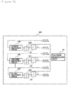
- FIG. 2 is a view schematically illustrating an apparatus for detecting a failure of a battery pack which is capable of detecting failure of a relay according to an exemplary embodiment.
- An apparatus 100 for detecting a failure of a battery pack includes a first battery pack 110, a second battery pack 111, a N-th battery pack 112, a first ground unit 120, a second ground unit 121, a N-th ground unit 122, a first relay 130, a second relay 131, a N-th relay 132, and a voltage measuring unit 14.
- the first battery pack 110, the second battery pack 111, and the N-th battery pack 112 are connected in parallel and supply power to the load.
- Each of the first battery pack 110, the second battery pack 111, and the N-th battery pack 112 may be formed such that one or more battery cells are connected in series and parallel.
- a type of battery cells which configure the first battery pack 110, the second battery pack 111, and the N-th battery pack 112 is not limited.
- the battery cell may be configured by a lead storage battery, a nickel-cadmium battery, a nickel hydrogen storage battery, a lithium ion battery, or a lithium ion polymer battery.
- the first relay 130, the second relay 131, and the N-th relay 132 are connected to the battery pack to connect or disconnect the power of the battery pack which is supplied to the load.
- the first relay 130, the second relay 131, and the N-th relay 132 are closed, the connected first battery pack 110, second battery pack 111, and N-th battery pack 112 are connected to the load to supply power to the load.
- the relays are open, the first battery pack 110, the second battery pack 111, and the N-th battery pack 112 are disconnected from the load to perform an operation of disconnecting the power from the load.
- the voltage measuring unit 14 is connected to both ends of one or more relays 13 to measure the voltages.
- first relay 130 second relay 131, and N-th relay 132 are not limited and for example, may be configured by a mechanical relay, a photoMOS relay, or a solid state relay.
- Relays are additionally configured at positive electrodes of the first battery pack 110, the second battery pack 111, and the N-th battery pack 112 to be controlled together with the relays which are previously connected to the respective battery packs.
- the first ground unit 120, the second ground unit 121, and the N-th ground unit 122 may be separately provided between the battery packs and the relays such that the ground units are not connected to each other.
- the first to N-th ground units 120, 121, and 122 may separately make the voltage between the battery pack and the relay be a reference voltage. Further, in FIG. 1 , even though the first ground unit 120, the second ground unit 121, and the N-the ground unit 122 are provided between the battery packs and the relays, in some exemplary embodiments, the relay may be provided between the battery pack and the ground unit.
- the voltage measuring unit 14 is connected to both ends of one or more relays such as the first relay 130, the second relay 131, and the N-th relay 132 to measure the voltages thoseof.
- the voltage measuring unit 14 measures the voltage of each relay whose one end is connected to the separate ground unit to separately measure the voltages of the relays to individually detect the failure of the relay.
- the voltage measuring unit 14 controls the relay to be closed and then measure whether voltages of both ends of each relay are equal to each other so that the failure of each relay may be detected according to the voltage measurement result.
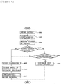
- FIG. 3 is a view illustrating a failure detecting operation procedure of an apparatus for detecting a failure of a battery pack
- FIG. 4 is a view schematically illustrating an apparatus for detecting a failure of a battery pack according to an exemplary embodiment of the present invention which is capable of detecting failure of a relay.
- a relay is controlled such that a first relay 130 to which a first ground unit 110 is connected is closed (S201).
- the voltage measuring unit 140 is connected to both ends of the first relay 130 to measure voltages of both ends of the first relay 130 (S202) and compares the voltages values of both ends of the first relay 130 to determine whether the voltages are equal to each other (S203).
- the failure of the first relay 130 may be detected (S204).
- the voltage measuring unit 14 measures voltages of both ends of the first relay 130 again.
- step S202 the voltage measuring unit 140 is connected to both ends of the second relay 231 to separately measure voltages of both ends of the second relay 231.
- step S203 the voltage measuring unit 140 determines whether voltages of both ends of the second relay 231 are different from each other in step S203 based on a result obtained by measuring the voltages of both ends of the second relay 231 to detect whether the second relay has failure (S204).
Landscapes
- Engineering & Computer Science (AREA)
- Chemical & Material Sciences (AREA)
- General Chemical & Material Sciences (AREA)
- Electrochemistry (AREA)
- Chemical Kinetics & Catalysis (AREA)
- Physics & Mathematics (AREA)
- General Physics & Mathematics (AREA)
- Power Engineering (AREA)
- Manufacturing & Machinery (AREA)
- Life Sciences & Earth Sciences (AREA)
- Mechanical Engineering (AREA)
- Transportation (AREA)
- Sustainable Energy (AREA)
- Sustainable Development (AREA)
- Secondary Cells (AREA)
- Testing Of Short-Circuits, Discontinuities, Leakage, Or Incorrect Line Connections (AREA)
- Charge And Discharge Circuits For Batteries Or The Like (AREA)
Abstract
Description
- This application claims priority to and the benefit of Korean Patent Application No.
10-2016-0116602 - The present invention relates to apparatus and method for detecting failure of battery pack using an independent ground unit, and more particularly, to an apparatus for detecting a failure of a battery pack using an independent ground unit which includes an independent ground unit between a battery pack and a relay and measures voltages of both ends of the relay to detect failure of the relay based on the measured value and a method for detecting a failure of a battery pack.
- In a battery for a vehicle, a secondary cell is used as an energy source of a driving motor which drives a vehicle.
- Generally, the secondary cell is formed with a configuration in which a plurality of unit battery packs is connected in parallel and the battery packs share one ground unit.
- In the meantime, in a structure in which a plurality of battery packs connected in parallel uses one ground unit, even when failure occurs in a relay, a voltage difference between both ends of the relay is not generated due to the combined ground unit so that the failure of the relay cannot be detected.
- The present invention is conceived to solve the above described problem and an object of the present invention is to provide an apparatus for detecting a failure of a battery pack which includes an independent ground unit between a battery pack and a relay to detect failure of the relay by a voltage difference at both ends of the relay when failure occurs in the relay and a method for detecting a failure of a battery pack.
- According to an exemplary embodiment of the present invention, an apparatus for detecting a failure of a battery pack includes a first battery pack which supplies power to a load; a first ground unit which is connected between a first relay which is connected to the first battery pack to connect and disconnect power supplying of the battery pack and the first battery pack; a second battery pack which supplies power to a load; a second ground unit which is connected between a second relay which is connected to the second battery pack to connect and disconnect power supplying of the battery pack and the second battery pack; and a voltage measuring unit which measures voltages of both ends of the first relay and voltages of both ends of the second relay, In an exemplary embodiment, the first and second ground units may make differences of voltages of both ends of the first and second relays by making a voltage between the first and second battery packs and the first and second relays be a reference voltage in order to detect failure of the first and second relays.
- In an exemplary embodiment, the voltage measuring unit may be connected to both ends of each of the first and second relay to measure a voltage.
- In an exemplary embodiment, the voltage measuring unit may detect failure of the first and second relays based on the voltage measurement result.
- According to another exemplary embodiment of the present invention, a method of detecting failure by a power supply device includes: controlling a first relay and a second relay to close the first relay whose one end is connected to a first ground unit and the second relay whose one end is connected to a second ground unit; measuring a voltage at both ends of the first relay and a voltage at both ends of the second relay; determining whether the measured voltages of both ends of the first relay are equal to each other and the measured voltages of both ends of the second relay are equal to each other; and detecting failure of the first and second relays based on a determination result.
- In an exemplary embodiment, when voltages of both ends of any of the first and second relays are not equal to each other, the detecting of failure of the first and second relays may include detecting a relay in which voltages of both ends are not equal to each other as a failure relay.
- The apparatus for detecting a failure of a battery pack according to the exemplary embodiment of the present invention includes an independent ground unit between each battery pack and a relay connected to the battery pack to detect the failure of the relay by a voltage difference at both ends of each relay so that failure of the relay which is not detected when the relay is closed by the combined ground unit in an existing power supply device is detected.
- Further, since the failure of the relay is detected by measuring a voltage, a separate configuration to detect failure of the relay is not necessary so that a manufacturing cost of a circuit is saved.
-
-
FIG. 1 is a view schematically illustrating a configuration of a battery pack device of the related art. -
FIG. 2 is a view schematically illustrating an apparatus for detecting a failure of a battery pack which is capable of detecting failure of a relay. -
FIG. 3 is a view illustrating a failure detecting operation procedure of an apparatus for detecting a failure of a battery pack. -
FIG. 4 is a view schematically illustrating an apparatus for detecting a failure of a battery pack according to an exemplary embodiment of the present invention which is capable of detecting failure of a relay. - The present invention will be described in detail below with reference to the accompanying drawings. Herein, repeated description and the detailed description of a known function and configuration that may make the purpose of the present invention unnecessarily ambiguous will be omitted. Exemplary embodiments of the present invention are provided so that those skilled in the art may more completely understand the present invention. Accordingly, the shape, the size, etc., of elements in the figures may be exaggerated for explicit comprehension.
- In the specification, unless explicitly described to the contrary, the word "comprise" and variations such as "comprises" or "comprising" will be understood to imply the inclusion of stated elements but not the exclusion of any other elements.
- In addition, the term "-unit"described in the specification means a unit for processing at least one function and operation and can be implemented by hardware components or software components or combinations thereof.
-
FIG. 1 is a view schematically illustrating a configuration of abattery pack device 10 of the related art. - Referring to
FIG. 1 , thebattery pack device 10 includes abattery pack 11, aground unit 12, a relay 13, and avoltage measuring unit 14. - The
battery pack device 10 may be formed such that one ormore battery packs 11 are connected in parallel. - One or
more battery packs 11 supply power to a load and include a separate charging unit to charge thebattery pack 11. - Here, the load may mean an electric vehicle, a hybrid vehicle, a plug-in hybrid vehicle, an uninterruptible power supply, or an energy storage system.
- Further, one or
more battery packs 11 may be connected to one or more relays 13, respectively. - Further, one or
more battery packs 11 may include aground unit 12 connected in one. - Further, the relay 13 may connect or disconnect power supplying of the
battery pack 11 which is supplied to the load. - Here, the
voltage measuring unit 14 may selectively measure voltages of one or more relays 13. - The above-described
battery pack device 10 is different from a structure of theapparatus 100 for detecting a failure of a battery pack of the exemplary embodiment in that theground unit 12 connected in one is provided and one ormore battery packs 11 connected in parallel are connected through a common ground unit. - Here, when the
battery pack device 10 is controlled to close the relay to supply power from the battery pack to the load, if the relay normally operates, voltages of both ends of the relay need to be equal to each other. Here, when failure occurs in the relay so that when the relay is not normally closed, a voltage difference is generated at both ends of the relay. - However, in order to detect failure caused in the relay 13, the voltage difference at both ends of the relay needs to be generated. However, generally, a
common ground unit 12 is used for a board on which a circuit of thebattery pack device 10 is configured. In this case, one end of each of the relays 13 is connected to acommon ground unit 12 to have the same voltage so that thevoltage measuring unit 14 may not individually detect which relay has failure. - Here, the failure may mean contact fusing in the relay due to a high temperature of the relay, contact movement due to frequent opening and closing of the relay, increase of a contact resistance due to deformation of a contact unit of the relay, a contact failure of the relay due to abnormal current and voltage, and the like.
-
FIG. 2 is a view schematically illustrating an apparatus for detecting a failure of a battery pack which is capable of detecting failure of a relay according to an exemplary embodiment. - An
apparatus 100 for detecting a failure of a battery pack according to an exemplary embodiment includes afirst battery pack 110, asecond battery pack 111, a N-th battery pack 112, afirst ground unit 120, asecond ground unit 121, a N-th ground unit 122, afirst relay 130, asecond relay 131, a N-th relay 132, and avoltage measuring unit 14. - The
first battery pack 110, thesecond battery pack 111, and the N-th battery pack 112 are connected in parallel and supply power to the load. - Each of the
first battery pack 110, thesecond battery pack 111, and the N-th battery pack 112 may be formed such that one or more battery cells are connected in series and parallel. - Further, a type of battery cells which configure the
first battery pack 110, thesecond battery pack 111, and the N-th battery pack 112 is not limited. For example, the battery cell may be configured by a lead storage battery, a nickel-cadmium battery, a nickel hydrogen storage battery, a lithium ion battery, or a lithium ion polymer battery. - The
first relay 130, thesecond relay 131, and the N-th relay 132 are connected to the battery pack to connect or disconnect the power of the battery pack which is supplied to the load. - More specifically, when the
first relay 130, thesecond relay 131, and the N-th relay 132 are closed, the connectedfirst battery pack 110,second battery pack 111, and N-th battery pack 112 are connected to the load to supply power to the load. When the relays are open, thefirst battery pack 110, thesecond battery pack 111, and the N-th battery pack 112 are disconnected from the load to perform an operation of disconnecting the power from the load. - The
voltage measuring unit 14 is connected to both ends of one or more relays 13 to measure the voltages. - Here, the types of
first relay 130,second relay 131, and N-th relay 132 are not limited and for example, may be configured by a mechanical relay, a photoMOS relay, or a solid state relay. - Relays are additionally configured at positive electrodes of the
first battery pack 110, thesecond battery pack 111, and the N-th battery pack 112 to be controlled together with the relays which are previously connected to the respective battery packs. - The
first ground unit 120, thesecond ground unit 121, and the N-th ground unit 122 may be separately provided between the battery packs and the relays such that the ground units are not connected to each other. The first to N-th ground units FIG. 1 , even though thefirst ground unit 120, thesecond ground unit 121, and the N-theground unit 122 are provided between the battery packs and the relays, in some exemplary embodiments, the relay may be provided between the battery pack and the ground unit. - The
voltage measuring unit 14 is connected to both ends of one or more relays such as thefirst relay 130, thesecond relay 131, and the N-th relay 132 to measure the voltages thoseof. Thevoltage measuring unit 14 measures the voltage of each relay whose one end is connected to the separate ground unit to separately measure the voltages of the relays to individually detect the failure of the relay. As described above, thevoltage measuring unit 14 controls the relay to be closed and then measure whether voltages of both ends of each relay are equal to each other so that the failure of each relay may be detected according to the voltage measurement result. -
FIG. 3 is a view illustrating a failure detecting operation procedure of an apparatus for detecting a failure of a battery pack, andFIG. 4 is a view schematically illustrating an apparatus for detecting a failure of a battery pack according to an exemplary embodiment of the present invention which is capable of detecting failure of a relay. - Referring to
FIGS. 3 and4 , first, a relay is controlled such that afirst relay 130 to which afirst ground unit 110 is connected is closed (S201). - The
voltage measuring unit 140 is connected to both ends of thefirst relay 130 to measure voltages of both ends of the first relay 130 (S202) and compares the voltages values of both ends of thefirst relay 130 to determine whether the voltages are equal to each other (S203). - When it is determined that the voltage values measured at both ends of the
first relay 130 are not equal to each other, the failure of thefirst relay 130 may be detected (S204). - In contrast, when it is determined that the voltage values measured at both ends of the
first relay 130 are equal to each other, thevoltage measuring unit 14 measures voltages of both ends of thefirst relay 130 again. - Similarly, in step S202, the
voltage measuring unit 140 is connected to both ends of the second relay 231 to separately measure voltages of both ends of the second relay 231. Next, thevoltage measuring unit 140 determines whether voltages of both ends of the second relay 231 are different from each other in step S203 based on a result obtained by measuring the voltages of both ends of the second relay 231 to detect whether the second relay has failure (S204). - While a specific embodiment of the present invention has been illustrated and described, it is obvious to those skilled in the art that the technical spirit of the present invention is not limited to the accompanying drawings and the above description and various modifications may be made without departing from the spirit of the present invention. Further, it is understood that such modifications will be covered by the claims of the present invention within the spirit of the present invention.
Claims (7)
- A power supply device, comprising:a first battery pack which supplies power to a load;a first ground unit which is connected between a first relay which is connected to the first battery pack to connect and disconnect power supplying of the battery pack and the first battery pack;a second battery pack which supplies power to the load;a second ground unit which is connected between a second relay which is connected to the second battery pack to connect and disconnect power supplying of the battery pack and the second battery pack; anda voltage measuring unit which measures voltages of both ends of the first relay and voltages of both ends of the second relay,wherein the first ground unit and the second ground unit are separately provided so as not to be connected to each other.
- The power supply device of claim 1, wherein the first and second ground units make differences of voltages of both ends of the first and second relays by making a voltage between the first and second battery packs and the first and second relays be a reference voltage in order to detect a failure of the first and second relays.
- The power supply device of claim 1, wherein the voltage measuring unit is connected to both ends of each of the first and second relay to measure a voltage.
- The power supply device of claim 3, wherein the voltage measuring unit detects failure of the first and second relays based on the voltage measurement result.
- The power supply device of claim 1, wherein the first battery pack and the second battery pack are connected in parallel.
- A method for detecting failure by a power supply device, the method comprising:controlling a first relay and a second relay to close the first relay whose one end is connected to a first ground unit and the second relay whose one end is connected to a second ground unit;measuring voltages of both ends of the first relay and voltages of both ends of the second relay;determining whether the measured voltages of both ends of the first relay are equal to each other and the measured voltages of both ends of the second relay are equal to each other; anddetecting failure of the first and second relays based on a determination result.
- The method of claim 6, wherein when voltages of both ends of any of the first and second relays are not equal to each other, the detecting of failure of the first and second relays includes detecting a relay in which voltages of both ends are not equal to each other as a failure relay.
Applications Claiming Priority (2)
| Application Number | Priority Date | Filing Date | Title |
|---|---|---|---|
| KR1020160116602A KR102044598B1 (en) | 2016-09-09 | 2016-09-09 | Apparatus and method for detect malfunction of battery pack |
| PCT/KR2017/009371 WO2018048128A1 (en) | 2016-09-09 | 2017-08-28 | Apparatus and method for detecting failure of battery pack |
Publications (3)
| Publication Number | Publication Date |
|---|---|
| EP3447512A1 true EP3447512A1 (en) | 2019-02-27 |
| EP3447512A4 EP3447512A4 (en) | 2019-04-24 |
| EP3447512B1 EP3447512B1 (en) | 2023-02-15 |
Family
ID=61562900
Family Applications (1)
| Application Number | Title | Priority Date | Filing Date |
|---|---|---|---|
| EP17849012.4A Active EP3447512B1 (en) | 2016-09-09 | 2017-08-28 | Apparatus and method for detecting failure of relay |
Country Status (6)
| Country | Link |
|---|---|
| US (1) | US10892527B2 (en) |
| EP (1) | EP3447512B1 (en) |
| JP (1) | JP6921123B2 (en) |
| KR (1) | KR102044598B1 (en) |
| CN (1) | CN109219754B (en) |
| WO (1) | WO2018048128A1 (en) |
Cited By (1)
| Publication number | Priority date | Publication date | Assignee | Title |
|---|---|---|---|---|
| EP3967543A1 (en) * | 2020-09-10 | 2022-03-16 | Altra S.p.A. | Battery for an electric vehicle, power supply system of an electric vehicle including an array of such batteries, and electric vehicle |
Families Citing this family (9)
| Publication number | Priority date | Publication date | Assignee | Title |
|---|---|---|---|---|
| KR102433848B1 (en) * | 2018-09-12 | 2022-08-17 | 주식회사 엘지에너지솔루션 | Apparatus and method for diagnosing switch |
| KR102827948B1 (en) * | 2019-11-21 | 2025-07-01 | 주식회사 엘지에너지솔루션 | Diagnostic circuit of parallel structure MOSFET comprising MUX and diagnostic method using the same |
| KR102785104B1 (en) * | 2019-12-20 | 2025-03-21 | 주식회사 엘지에너지솔루션 | Apparatus and method for diagnosing parallel battery relay |
| JP7348108B2 (en) * | 2020-03-06 | 2023-09-20 | 株式会社日立国際電気 | battery unit |
| KR102729158B1 (en) | 2020-06-08 | 2024-11-12 | 주식회사 엘지에너지솔루션 | Relay diagnosis apparatus, relay diagnosis method, battery system, and electric vehicle |
| KR20220012044A (en) | 2020-07-22 | 2022-02-03 | 주식회사 엘지에너지솔루션 | Battery apparatus, battery management system, and method of diagonsing supply voltage of contactor |
| KR102753193B1 (en) * | 2020-10-19 | 2025-01-09 | 주식회사 엘지에너지솔루션 | Diagnostic circuit of parallel structure FET comprising LDO and Shunt resistor, and diagnostic method using the same |
| KR102918559B1 (en) * | 2021-10-15 | 2026-01-27 | 주식회사 엘지에너지솔루션 | Battery managing apparatus and operating method of the same |
| JP2025002478A (en) * | 2023-06-22 | 2025-01-09 | 株式会社クボタ | Electric working machine and method for starting electric working machine |
Family Cites Families (20)
| Publication number | Priority date | Publication date | Assignee | Title |
|---|---|---|---|---|
| JP2900036B2 (en) * | 1989-03-08 | 1999-06-02 | 安藤電気株式会社 | Relay Matrix Ground Circuit |
| JPH07296695A (en) * | 1994-04-28 | 1995-11-10 | Sanyo Electric Co Ltd | Relay contact abnormality detecting circuit |
| JP3945630B2 (en) * | 2002-01-10 | 2007-07-18 | パナソニック・イーブイ・エナジー株式会社 | Relay contact welding inspection method for battery power supply |
| US7683575B2 (en) | 2007-07-18 | 2010-03-23 | Tesla Motors, Inc. | Method and apparatus for identifying and disconnecting short-circuited battery cells within a battery pack |
| CN101826737B (en) | 2009-03-06 | 2012-05-30 | 登丰微电子股份有限公司 | Battery charging control device and battery balance charging controller |
| FR2948461B1 (en) | 2009-07-24 | 2011-07-01 | Renault Sa | METHOD FOR DIAGNOSING THE OPERATION OF A DEVICE FOR CUTTING AND CONNECTING A BATTERY TO A MOTOR VEHICLE EDGE NETWORK |
| JP5477778B2 (en) * | 2010-05-28 | 2014-04-23 | スズキ株式会社 | Control device for battery parallel connection circuit |
| US8901934B2 (en) * | 2010-10-29 | 2014-12-02 | GM Global Technology Operations LLC | Diagnosis of HEV/EV battery disconnect system |
| TWI451112B (en) | 2012-06-21 | 2014-09-01 | Via Tech Inc | Battery management system |
| KR20140013250A (en) | 2012-07-23 | 2014-02-05 | 현대모비스 주식회사 | Vehicle power supply with multi battery packs and power control method therof |
| JP5983171B2 (en) * | 2012-08-10 | 2016-08-31 | 株式会社Gsユアサ | Switch failure diagnosis device, power storage device |
| KR20140125971A (en) | 2013-04-19 | 2014-10-30 | 삼성에스디아이 주식회사 | Dual battery pack and operating method thereof |
| CN104142470A (en) | 2013-05-10 | 2014-11-12 | 台达电子工业股份有限公司 | Relay detection device and operation method thereof |
| KR102052956B1 (en) * | 2013-05-21 | 2019-12-09 | 엘지이노텍 주식회사 | Relay checking device of battery pack and Battery control system |
| JP5751282B2 (en) * | 2013-05-29 | 2015-07-22 | 株式会社デンソー | Control device |
| KR101562016B1 (en) * | 2013-08-29 | 2015-11-18 | 주식회사 엘지화학 | Apparatus and Method for diagnosis of cell balancing switch |
| JP2015122864A (en) | 2013-12-24 | 2015-07-02 | 株式会社豊田自動織機 | Relay error detection method |
| KR102210282B1 (en) | 2014-05-30 | 2021-02-01 | 삼성전자주식회사 | Method and apparatus for detecting condition of relay |
| JP6196188B2 (en) * | 2014-06-17 | 2017-09-13 | 株式会社東芝 | ANTENNA DEVICE AND RADIO DEVICE |
| JP6281578B2 (en) * | 2016-01-20 | 2018-02-21 | 船井電機株式会社 | Antenna device and communication device |
-
2016
- 2016-09-09 KR KR1020160116602A patent/KR102044598B1/en active Active
-
2017
- 2017-08-28 WO PCT/KR2017/009371 patent/WO2018048128A1/en not_active Ceased
- 2017-08-28 JP JP2018559742A patent/JP6921123B2/en active Active
- 2017-08-28 US US16/307,754 patent/US10892527B2/en active Active
- 2017-08-28 CN CN201780032470.8A patent/CN109219754B/en active Active
- 2017-08-28 EP EP17849012.4A patent/EP3447512B1/en active Active
Cited By (1)
| Publication number | Priority date | Publication date | Assignee | Title |
|---|---|---|---|---|
| EP3967543A1 (en) * | 2020-09-10 | 2022-03-16 | Altra S.p.A. | Battery for an electric vehicle, power supply system of an electric vehicle including an array of such batteries, and electric vehicle |
Also Published As
| Publication number | Publication date |
|---|---|
| JP2019517102A (en) | 2019-06-20 |
| EP3447512A4 (en) | 2019-04-24 |
| EP3447512B1 (en) | 2023-02-15 |
| CN109219754B (en) | 2021-05-28 |
| US20190267679A1 (en) | 2019-08-29 |
| CN109219754A (en) | 2019-01-15 |
| JP6921123B2 (en) | 2021-08-18 |
| KR20180028800A (en) | 2018-03-19 |
| WO2018048128A1 (en) | 2018-03-15 |
| KR102044598B1 (en) | 2019-11-13 |
| US10892527B2 (en) | 2021-01-12 |
Similar Documents
| Publication | Publication Date | Title |
|---|---|---|
| US10892527B2 (en) | Apparatus and method for detecting failure of battery pack | |
| US10707686B2 (en) | Battery management | |
| US9373973B2 (en) | Apparatus, system, and method of preventing battery rack damage by measuring current | |
| EP2930811B1 (en) | Apparatus, system and method for preventing damage to battery rack by means of voltage measurement | |
| EP4253972B1 (en) | Battery diagnosis device, battery management system, battery pack, electric vehicle, and battery diagnosis method | |
| EP3206042B1 (en) | Switch deterioration detection device and method | |
| CN105051552A (en) | Fault detection device for voltage sensor | |
| CN107251312A (en) | Modularized design for 48 V Li-ion batteries of easy assembly and disassembly | |
| US20150229144A1 (en) | Battery management system | |
| KR20120077482A (en) | Balance charging apparatus for battery module | |
| CN114556739A (en) | Individual discharge system and method for battery rack | |
| US11114703B2 (en) | Battery pack | |
| KR20130077134A (en) | Mathod for detecting fault of battery cell | |
| EP2916138B1 (en) | Battery pack test system and method for testing said battery pack | |
| EP4365613B1 (en) | Battery pack and operating method thereof | |
| EP4160782B1 (en) | Battery disconnect unit including moving plate | |
| EP4303600B1 (en) | Voltage determination circuit | |
| KR20250097496A (en) | Battery management apparatus and operating method of the same | |
| KR20250092893A (en) | Battery diagnosis apparatus and operating method of the same | |
| KR20170090137A (en) | Method for driving of Battery management system |
Legal Events
| Date | Code | Title | Description |
|---|---|---|---|
| STAA | Information on the status of an ep patent application or granted ep patent |
Free format text: STATUS: THE INTERNATIONAL PUBLICATION HAS BEEN MADE |
|
| PUAI | Public reference made under article 153(3) epc to a published international application that has entered the european phase |
Free format text: ORIGINAL CODE: 0009012 |
|
| STAA | Information on the status of an ep patent application or granted ep patent |
Free format text: STATUS: REQUEST FOR EXAMINATION WAS MADE |
|
| 17P | Request for examination filed |
Effective date: 20181123 |
|
| AK | Designated contracting states |
Kind code of ref document: A1 Designated state(s): AL AT BE BG CH CY CZ DE DK EE ES FI FR GB GR HR HU IE IS IT LI LT LU LV MC MK MT NL NO PL PT RO RS SE SI SK SM TR |
|
| AX | Request for extension of the european patent |
Extension state: BA ME |
|
| A4 | Supplementary search report drawn up and despatched |
Effective date: 20190322 |
|
| RIC1 | Information provided on ipc code assigned before grant |
Ipc: G01R 31/40 20140101ALI20190318BHEP Ipc: H01M 10/48 20060101ALI20190318BHEP Ipc: G01R 31/327 20060101AFI20190318BHEP Ipc: G01R 19/165 20060101ALN20190318BHEP |
|
| DAV | Request for validation of the european patent (deleted) | ||
| DAX | Request for extension of the european patent (deleted) | ||
| RAP1 | Party data changed (applicant data changed or rights of an application transferred) |
Owner name: LG ENERGY SOLUTION LTD. |
|
| RAP3 | Party data changed (applicant data changed or rights of an application transferred) |
Owner name: LG ENERGY SOLUTION, LTD. |
|
| REG | Reference to a national code |
Ref country code: DE Ref legal event code: R079 Ref document number: 602017066095 Country of ref document: DE Free format text: PREVIOUS MAIN CLASS: G01R0031360000 Ipc: G01R0031327000 |
|
| GRAP | Despatch of communication of intention to grant a patent |
Free format text: ORIGINAL CODE: EPIDOSNIGR1 |
|
| STAA | Information on the status of an ep patent application or granted ep patent |
Free format text: STATUS: GRANT OF PATENT IS INTENDED |
|
| RIC1 | Information provided on ipc code assigned before grant |
Ipc: G01R 19/165 20060101ALN20220801BHEP Ipc: H01M 50/569 20210101ALI20220801BHEP Ipc: H01M 50/512 20210101ALI20220801BHEP Ipc: H01M 50/50 20210101ALI20220801BHEP Ipc: B60L 50/60 20190101ALI20220801BHEP Ipc: H01M 10/48 20060101ALI20220801BHEP Ipc: G01R 31/40 20140101ALI20220801BHEP Ipc: G01R 31/327 20060101AFI20220801BHEP |
|
| INTG | Intention to grant announced |
Effective date: 20220905 |
|
| GRAS | Grant fee paid |
Free format text: ORIGINAL CODE: EPIDOSNIGR3 |
|
| GRAA | (expected) grant |
Free format text: ORIGINAL CODE: 0009210 |
|
| STAA | Information on the status of an ep patent application or granted ep patent |
Free format text: STATUS: THE PATENT HAS BEEN GRANTED |
|
| AK | Designated contracting states |
Kind code of ref document: B1 Designated state(s): AL AT BE BG CH CY CZ DE DK EE ES FI FR GB GR HR HU IE IS IT LI LT LU LV MC MK MT NL NO PL PT RO RS SE SI SK SM TR |
|
| REG | Reference to a national code |
Ref country code: CH Ref legal event code: EP Ref country code: GB Ref legal event code: FG4D |
|
| REG | Reference to a national code |
Ref country code: DE Ref legal event code: R096 Ref document number: 602017066095 Country of ref document: DE |
|
| REG | Reference to a national code |
Ref country code: AT Ref legal event code: REF Ref document number: 1548483 Country of ref document: AT Kind code of ref document: T Effective date: 20230315 Ref country code: IE Ref legal event code: FG4D |
|
| REG | Reference to a national code |
Ref country code: LT Ref legal event code: MG9D |
|
| REG | Reference to a national code |
Ref country code: NL Ref legal event code: MP Effective date: 20230215 |
|
| P01 | Opt-out of the competence of the unified patent court (upc) registered |
Effective date: 20230525 |
|
| REG | Reference to a national code |
Ref country code: AT Ref legal event code: MK05 Ref document number: 1548483 Country of ref document: AT Kind code of ref document: T Effective date: 20230215 |
|
| PG25 | Lapsed in a contracting state [announced via postgrant information from national office to epo] |
Ref country code: RS Free format text: LAPSE BECAUSE OF FAILURE TO SUBMIT A TRANSLATION OF THE DESCRIPTION OR TO PAY THE FEE WITHIN THE PRESCRIBED TIME-LIMIT Effective date: 20230215 Ref country code: PT Free format text: LAPSE BECAUSE OF FAILURE TO SUBMIT A TRANSLATION OF THE DESCRIPTION OR TO PAY THE FEE WITHIN THE PRESCRIBED TIME-LIMIT Effective date: 20230615 Ref country code: NO Free format text: LAPSE BECAUSE OF FAILURE TO SUBMIT A TRANSLATION OF THE DESCRIPTION OR TO PAY THE FEE WITHIN THE PRESCRIBED TIME-LIMIT Effective date: 20230515 Ref country code: NL Free format text: LAPSE BECAUSE OF FAILURE TO SUBMIT A TRANSLATION OF THE DESCRIPTION OR TO PAY THE FEE WITHIN THE PRESCRIBED TIME-LIMIT Effective date: 20230215 Ref country code: LV Free format text: LAPSE BECAUSE OF FAILURE TO SUBMIT A TRANSLATION OF THE DESCRIPTION OR TO PAY THE FEE WITHIN THE PRESCRIBED TIME-LIMIT Effective date: 20230215 Ref country code: LT Free format text: LAPSE BECAUSE OF FAILURE TO SUBMIT A TRANSLATION OF THE DESCRIPTION OR TO PAY THE FEE WITHIN THE PRESCRIBED TIME-LIMIT Effective date: 20230215 Ref country code: HR Free format text: LAPSE BECAUSE OF FAILURE TO SUBMIT A TRANSLATION OF THE DESCRIPTION OR TO PAY THE FEE WITHIN THE PRESCRIBED TIME-LIMIT Effective date: 20230215 Ref country code: ES Free format text: LAPSE BECAUSE OF FAILURE TO SUBMIT A TRANSLATION OF THE DESCRIPTION OR TO PAY THE FEE WITHIN THE PRESCRIBED TIME-LIMIT Effective date: 20230215 Ref country code: AT Free format text: LAPSE BECAUSE OF FAILURE TO SUBMIT A TRANSLATION OF THE DESCRIPTION OR TO PAY THE FEE WITHIN THE PRESCRIBED TIME-LIMIT Effective date: 20230215 |
|
| PG25 | Lapsed in a contracting state [announced via postgrant information from national office to epo] |
Ref country code: SE Free format text: LAPSE BECAUSE OF FAILURE TO SUBMIT A TRANSLATION OF THE DESCRIPTION OR TO PAY THE FEE WITHIN THE PRESCRIBED TIME-LIMIT Effective date: 20230215 Ref country code: PL Free format text: LAPSE BECAUSE OF FAILURE TO SUBMIT A TRANSLATION OF THE DESCRIPTION OR TO PAY THE FEE WITHIN THE PRESCRIBED TIME-LIMIT Effective date: 20230215 Ref country code: IS Free format text: LAPSE BECAUSE OF FAILURE TO SUBMIT A TRANSLATION OF THE DESCRIPTION OR TO PAY THE FEE WITHIN THE PRESCRIBED TIME-LIMIT Effective date: 20230615 Ref country code: GR Free format text: LAPSE BECAUSE OF FAILURE TO SUBMIT A TRANSLATION OF THE DESCRIPTION OR TO PAY THE FEE WITHIN THE PRESCRIBED TIME-LIMIT Effective date: 20230516 Ref country code: FI Free format text: LAPSE BECAUSE OF FAILURE TO SUBMIT A TRANSLATION OF THE DESCRIPTION OR TO PAY THE FEE WITHIN THE PRESCRIBED TIME-LIMIT Effective date: 20230215 |
|
| PG25 | Lapsed in a contracting state [announced via postgrant information from national office to epo] |
Ref country code: SM Free format text: LAPSE BECAUSE OF FAILURE TO SUBMIT A TRANSLATION OF THE DESCRIPTION OR TO PAY THE FEE WITHIN THE PRESCRIBED TIME-LIMIT Effective date: 20230215 Ref country code: RO Free format text: LAPSE BECAUSE OF FAILURE TO SUBMIT A TRANSLATION OF THE DESCRIPTION OR TO PAY THE FEE WITHIN THE PRESCRIBED TIME-LIMIT Effective date: 20230215 Ref country code: EE Free format text: LAPSE BECAUSE OF FAILURE TO SUBMIT A TRANSLATION OF THE DESCRIPTION OR TO PAY THE FEE WITHIN THE PRESCRIBED TIME-LIMIT Effective date: 20230215 Ref country code: DK Free format text: LAPSE BECAUSE OF FAILURE TO SUBMIT A TRANSLATION OF THE DESCRIPTION OR TO PAY THE FEE WITHIN THE PRESCRIBED TIME-LIMIT Effective date: 20230215 Ref country code: CZ Free format text: LAPSE BECAUSE OF FAILURE TO SUBMIT A TRANSLATION OF THE DESCRIPTION OR TO PAY THE FEE WITHIN THE PRESCRIBED TIME-LIMIT Effective date: 20230215 |
|
| REG | Reference to a national code |
Ref country code: DE Ref legal event code: R097 Ref document number: 602017066095 Country of ref document: DE |
|
| PG25 | Lapsed in a contracting state [announced via postgrant information from national office to epo] |
Ref country code: SK Free format text: LAPSE BECAUSE OF FAILURE TO SUBMIT A TRANSLATION OF THE DESCRIPTION OR TO PAY THE FEE WITHIN THE PRESCRIBED TIME-LIMIT Effective date: 20230215 |
|
| PLBE | No opposition filed within time limit |
Free format text: ORIGINAL CODE: 0009261 |
|
| STAA | Information on the status of an ep patent application or granted ep patent |
Free format text: STATUS: NO OPPOSITION FILED WITHIN TIME LIMIT |
|
| 26N | No opposition filed |
Effective date: 20231116 |
|
| PG25 | Lapsed in a contracting state [announced via postgrant information from national office to epo] |
Ref country code: SI Free format text: LAPSE BECAUSE OF FAILURE TO SUBMIT A TRANSLATION OF THE DESCRIPTION OR TO PAY THE FEE WITHIN THE PRESCRIBED TIME-LIMIT Effective date: 20230215 |
|
| PG25 | Lapsed in a contracting state [announced via postgrant information from national office to epo] |
Ref country code: MC Free format text: LAPSE BECAUSE OF FAILURE TO SUBMIT A TRANSLATION OF THE DESCRIPTION OR TO PAY THE FEE WITHIN THE PRESCRIBED TIME-LIMIT Effective date: 20230215 |
|
| REG | Reference to a national code |
Ref country code: CH Ref legal event code: PL |
|
| PG25 | Lapsed in a contracting state [announced via postgrant information from national office to epo] |
Ref country code: MC Free format text: LAPSE BECAUSE OF FAILURE TO SUBMIT A TRANSLATION OF THE DESCRIPTION OR TO PAY THE FEE WITHIN THE PRESCRIBED TIME-LIMIT Effective date: 20230215 |
|
| PG25 | Lapsed in a contracting state [announced via postgrant information from national office to epo] |
Ref country code: LU Free format text: LAPSE BECAUSE OF NON-PAYMENT OF DUE FEES Effective date: 20230828 |
|
| PG25 | Lapsed in a contracting state [announced via postgrant information from national office to epo] |
Ref country code: LU Free format text: LAPSE BECAUSE OF NON-PAYMENT OF DUE FEES Effective date: 20230828 Ref country code: CH Free format text: LAPSE BECAUSE OF NON-PAYMENT OF DUE FEES Effective date: 20230831 |
|
| REG | Reference to a national code |
Ref country code: BE Ref legal event code: MM Effective date: 20230831 |
|
| REG | Reference to a national code |
Ref country code: IE Ref legal event code: MM4A |
|
| PG25 | Lapsed in a contracting state [announced via postgrant information from national office to epo] |
Ref country code: IT Free format text: LAPSE BECAUSE OF FAILURE TO SUBMIT A TRANSLATION OF THE DESCRIPTION OR TO PAY THE FEE WITHIN THE PRESCRIBED TIME-LIMIT Effective date: 20230215 |
|
| PG25 | Lapsed in a contracting state [announced via postgrant information from national office to epo] |
Ref country code: IE Free format text: LAPSE BECAUSE OF NON-PAYMENT OF DUE FEES Effective date: 20230828 |
|
| PG25 | Lapsed in a contracting state [announced via postgrant information from national office to epo] |
Ref country code: IE Free format text: LAPSE BECAUSE OF NON-PAYMENT OF DUE FEES Effective date: 20230828 |
|
| PG25 | Lapsed in a contracting state [announced via postgrant information from national office to epo] |
Ref country code: BE Free format text: LAPSE BECAUSE OF NON-PAYMENT OF DUE FEES Effective date: 20230831 |
|
| PG25 | Lapsed in a contracting state [announced via postgrant information from national office to epo] |
Ref country code: BG Free format text: LAPSE BECAUSE OF FAILURE TO SUBMIT A TRANSLATION OF THE DESCRIPTION OR TO PAY THE FEE WITHIN THE PRESCRIBED TIME-LIMIT Effective date: 20230215 |
|
| PG25 | Lapsed in a contracting state [announced via postgrant information from national office to epo] |
Ref country code: BG Free format text: LAPSE BECAUSE OF FAILURE TO SUBMIT A TRANSLATION OF THE DESCRIPTION OR TO PAY THE FEE WITHIN THE PRESCRIBED TIME-LIMIT Effective date: 20230215 |
|
| PG25 | Lapsed in a contracting state [announced via postgrant information from national office to epo] |
Ref country code: CY Free format text: LAPSE BECAUSE OF FAILURE TO SUBMIT A TRANSLATION OF THE DESCRIPTION OR TO PAY THE FEE WITHIN THE PRESCRIBED TIME-LIMIT; INVALID AB INITIO Effective date: 20170828 |
|
| PG25 | Lapsed in a contracting state [announced via postgrant information from national office to epo] |
Ref country code: HU Free format text: LAPSE BECAUSE OF FAILURE TO SUBMIT A TRANSLATION OF THE DESCRIPTION OR TO PAY THE FEE WITHIN THE PRESCRIBED TIME-LIMIT; INVALID AB INITIO Effective date: 20170828 |
|
| PGFP | Annual fee paid to national office [announced via postgrant information from national office to epo] |
Ref country code: DE Payment date: 20250721 Year of fee payment: 9 |
|
| PGFP | Annual fee paid to national office [announced via postgrant information from national office to epo] |
Ref country code: GB Payment date: 20250722 Year of fee payment: 9 |
|
| PGFP | Annual fee paid to national office [announced via postgrant information from national office to epo] |
Ref country code: FR Payment date: 20250725 Year of fee payment: 9 |
|
| PG25 | Lapsed in a contracting state [announced via postgrant information from national office to epo] |
Ref country code: TR Free format text: LAPSE BECAUSE OF FAILURE TO SUBMIT A TRANSLATION OF THE DESCRIPTION OR TO PAY THE FEE WITHIN THE PRESCRIBED TIME-LIMIT Effective date: 20230215 |