EP3447501A1 - Rotary machine - Google Patents
Rotary machine Download PDFInfo
- Publication number
- EP3447501A1 EP3447501A1 EP17810182.0A EP17810182A EP3447501A1 EP 3447501 A1 EP3447501 A1 EP 3447501A1 EP 17810182 A EP17810182 A EP 17810182A EP 3447501 A1 EP3447501 A1 EP 3447501A1
- Authority
- EP
- European Patent Office
- Prior art keywords
- magnetic sensor
- rotor
- magnet
- housing
- magnetic
- Prior art date
- Legal status (The legal status is an assumption and is not a legal conclusion. Google has not performed a legal analysis and makes no representation as to the accuracy of the status listed.)
- Withdrawn
Links
Images







Classifications
-
- G—PHYSICS
- G01—MEASURING; TESTING
- G01P—MEASURING LINEAR OR ANGULAR SPEED, ACCELERATION, DECELERATION, OR SHOCK; INDICATING PRESENCE, ABSENCE, OR DIRECTION, OF MOVEMENT
- G01P3/00—Measuring linear or angular speed; Measuring differences of linear or angular speeds
- G01P3/42—Devices characterised by the use of electric or magnetic means
- G01P3/44—Devices characterised by the use of electric or magnetic means for measuring angular speed
- G01P3/48—Devices characterised by the use of electric or magnetic means for measuring angular speed by measuring frequency of generated current or voltage
- G01P3/481—Devices characterised by the use of electric or magnetic means for measuring angular speed by measuring frequency of generated current or voltage of pulse signals
- G01P3/487—Devices characterised by the use of electric or magnetic means for measuring angular speed by measuring frequency of generated current or voltage of pulse signals delivered by rotating magnets
-
- F—MECHANICAL ENGINEERING; LIGHTING; HEATING; WEAPONS; BLASTING
- F01—MACHINES OR ENGINES IN GENERAL; ENGINE PLANTS IN GENERAL; STEAM ENGINES
- F01D—NON-POSITIVE DISPLACEMENT MACHINES OR ENGINES, e.g. STEAM TURBINES
- F01D17/00—Regulating or controlling by varying flow
- F01D17/02—Arrangement of sensing elements
- F01D17/06—Arrangement of sensing elements responsive to speed
-
- G—PHYSICS
- G01—MEASURING; TESTING
- G01D—MEASURING NOT SPECIALLY ADAPTED FOR A SPECIFIC VARIABLE; ARRANGEMENTS FOR MEASURING TWO OR MORE VARIABLES NOT COVERED IN A SINGLE OTHER SUBCLASS; TARIFF METERING APPARATUS; MEASURING OR TESTING NOT OTHERWISE PROVIDED FOR
- G01D5/00—Mechanical means for transferring the output of a sensing member; Means for converting the output of a sensing member to another variable where the form or nature of the sensing member does not constrain the means for converting; Transducers not specially adapted for a specific variable
- G01D5/12—Mechanical means for transferring the output of a sensing member; Means for converting the output of a sensing member to another variable where the form or nature of the sensing member does not constrain the means for converting; Transducers not specially adapted for a specific variable using electric or magnetic means
- G01D5/14—Mechanical means for transferring the output of a sensing member; Means for converting the output of a sensing member to another variable where the form or nature of the sensing member does not constrain the means for converting; Transducers not specially adapted for a specific variable using electric or magnetic means influencing the magnitude of a current or voltage
-
- G—PHYSICS
- G01—MEASURING; TESTING
- G01P—MEASURING LINEAR OR ANGULAR SPEED, ACCELERATION, DECELERATION, OR SHOCK; INDICATING PRESENCE, ABSENCE, OR DIRECTION, OF MOVEMENT
- G01P1/00—Details of instruments
-
- G—PHYSICS
- G01—MEASURING; TESTING
- G01P—MEASURING LINEAR OR ANGULAR SPEED, ACCELERATION, DECELERATION, OR SHOCK; INDICATING PRESENCE, ABSENCE, OR DIRECTION, OF MOVEMENT
- G01P1/00—Details of instruments
- G01P1/02—Housings
- G01P1/026—Housings for speed measuring devices, e.g. pulse generator
-
- F—MECHANICAL ENGINEERING; LIGHTING; HEATING; WEAPONS; BLASTING
- F05—INDEXING SCHEMES RELATING TO ENGINES OR PUMPS IN VARIOUS SUBCLASSES OF CLASSES F01-F04
- F05B—INDEXING SCHEME RELATING TO WIND, SPRING, WEIGHT, INERTIA OR LIKE MOTORS, TO MACHINES OR ENGINES FOR LIQUIDS COVERED BY SUBCLASSES F03B, F03D AND F03G
- F05B2220/00—Application
- F05B2220/40—Application in turbochargers
Definitions
- the present invention relates to a rotary machine such as a turbocharger.
- a rotary machine serving as a turbocharger, or the like
- a rotary machine that includes a rotor configured to axially rotate around a rotation axis and a housing configured to house the rotor
- the rotor has a magnet attached thereto so that the rotation speed of the rotor can be measured.
- the magnet is attached to the rotor such that the arrangement direction of a pair of magnetic poles is the same as the radial direction of the rotor.
- the rotary machine is provided with a magnetic sensor outside the housing.
- the rotary machine is configured such that the rotation speed of the rotor is detected on the basis of the time variation of the output of the magnetic sensor.
- the magnetic sensor is attached to the housing, and attempts to arrange the magnetic sensor as close as possible to the magnet have been made.
- techniques that make it possible to measure the rotation speed accurately with high sensitivity even when the rotation speed is extremely high, have been demanded.
- the magnetic sensor has only to be arranged at the position adjacent to the magnet in the radial direction of the rotor and the magnetic sensitive direction of the magnetic sensor has only to be the same as the radial direction (refer to FIG. 24 ). It is because it has been considered that such arrangement makes it possible to arrange the magnetic sensor close to the magnet, and at the same time to increase the output of the magnetic sensor because the magnetic field of the magnet acts on the magnetic sensor in the magnetism sensing direction.
- Patent Document 1 Japanese Patent No. 5032578
- the output of the magnetic sensor is lowered as the rotation speed of the rotor becomes high (refer to FIG. 25 ).
- This is considered, by the assumption, to be caused by an eddy current that generates in the housing.
- the housing is formed of a conductive material such as metal or the like, when the magnetic field of the magnet that acts on the housing varies with time by rotation of the magnet, an eddy current generates inside the housing.
- the lowering of the output of the magnetic sensor is considered to be caused by cancelling out of the magnetic field of the magnet by the magnetic field generated by the eddy current.
- the present invention has been made in view of such a background, and it is intended to provide a rotary machine in which the output of a magnetic sensor is hardly lowered even if the rotation speed of a rotor becomes high.
- One aspect of the present invention is a rotary machine including:
- the magnet is attached to the rotor such that the arrangement direction of the pair of magnetic poles is the same as the radial direction of the rotor.
- the magnetic sensor is attached to the housing. And, the magnetism sensing direction of the magnetic sensor is set orthogonal to the radial direction.
- the output of the magnetic sensor can remain at a high level even if the rotation speed of the rotor becomes high, to thereby detect the rotation speed of the rotor accurately.
- the present aspect can provide a rotary machine in which the output of the magnetic sensor is hardly lowered even if the rotation speed of the rotor becomes high.
- the magnetism sensing direction of the magnetic sensor is orthogonal to the radial direction.
- the magnetism sensing direction is orthogonal to the radial direction means that the direction (radial direction) parallel to a straight line SL which passes through the magnetic sensor 5 (refer to FIG. 3 ) and a rotation axis A and is orthogonal to the rotation axis A is orthogonal to the magnetism sensing direction of the magnetic sensor 5.
- orthogonal mentioned here is not strictly restricted, and is permitted to have some displacement. Specifically, displacement at the level of ⁇ 10°from the orthogonal can be accepted with no problem.
- the magnetic sensor is preferably arranged at a position apart from the magnet by a prescribed distance in an axial direction of the rotor.
- the magnetic sensor is preferably located on the inside than an intermediate position between an exterior surface and an interior surface of the housing in the radial direction.
- the magnetic sensor can be closer to the magnet.
- the output of the magnetic sensor can be increased. Accordingly, the rotation speed of the rotor can be detected more accurately.
- the housing has a recessed part recessively formed inward in the radial direction from the exterior surface of the housing, and the magnetic sensor is arranged in the recessed part.
- the magnetic sensor when manufacturing the rotary machine, the magnetic sensor can be easily disposed inside the housing from the outside of the housing. In this way, the rotary machine can be readily manufactured.
- the magnetic sensor when the magnetic sensor is disposed in the recessed part, the magnetic sensor can be arranged close to the magnet. Therefore, the output of the magnetic sensor can be increased to thereby detect the rotation speed of the rotor accurately.
- two or more of the magnetic sensors are provided, which differ from each other in output corresponding to the magnetic field generated from the magnet so that the difference of outputs between the two magnetic sensors is used to detect the rotation speed of the rotor.
- the rotary machine is used as a turbocharger
- the rotor is a compressor wheel of the turbocharger
- the housing is a compressor housing containing the compressor wheel
- the magnetic sensor is attached to the compressor housing.
- the compressor housing is an intake side housing of a turbocharger
- the temperature is lower than that of a turbine housing that is an exhaust side housing. Therefore, by attaching the magnetic sensor to the compressor housing, the magnetic sensor can be prevented from having a high temperature to thereby prevent shortening of the life of the magnetic sensor.
- the magnetic sensor is preferably a magneto-impedance sensor.
- a magneto-impedance sensor (hereinafter, also referred to as an MI sensor) has high sensitivity for detecting magnetism and is also excellent in high-speed response. Therefore, although other-type magnetic sensors also can be used, particularly in the case of high-speed rotation at 10000 rpm or higher, by using an MI sensor, time variation of the magnetic field of the magnet can be accurately detected, so that the rotation speed of the rotor can be accurately detected.
- the magnet is preferably attached to the rotation axis.
- the magnet When the magnet is attached to the rotation axis, the magnet is hardly affected by a centrifugal force accompanied with the rotation of the rotor. Accordingly, any failure, for example, dropping of the magnet by the centrifugal force, etc. can be prevented.
- a rotary machine 1 of the present embodiment includes a rotor 2, a housing 3, a magnet 4, and a magnetic sensor 5.
- the rotor 2 axially rotates around a rotation axis A.
- the housing 3 is formed of a conductive material and contains the rotor 2.
- the magnet 4 is attached to the rotor 2 in such a manner that the arrangement direction of a pair of magnetic poles is in a radial direction of the rotor 2.
- the magnetic sensor 5 is attached to the housing 3. The magnetic sensor 5 detects time variation of the magnetic field generated from the magnet 4. In this way, it is configured to detect rotation speed of the rotor 2.
- the magnetic sensor 5 is arranged on the outside than the magnet 4 in the radial direction.
- the magnetism sensing direction of the magnetic sensor 5 is orthogonal to the radial direction.
- the rotary machine 1 of the present embodiment is a turbocharger 1a that is to be installed in an engine of a vehicle, and the like.
- the turbocharger 1a includes a turbo wheel 11, a turbo housing 12 for housing the turbo wheel 11, a turbo shaft 13, a compressor wheel 2a, a compressor housing 3a for housing the compressor wheel 2a, an air inlet 30, an air outlet 14, an exhaust air inlet 15, and an exhaust air outlet 16.
- the turbo shaft 13 connects the turbo wheel 11 and the compressor wheel 2a.
- the rotor 2 of the present embodiment is the compressor wheel 2a of the turbocharger 1a.
- the housing 3 of the present embodiment is the compressor housing 3a.
- the magnetic sensor 5 is attached to the compressor housing 3a.
- the compressor housing 3a is made of aluminum.
- the magnet 4 of the present embodiment is attached such that the center coincides with the rotation axis A of the compressor wheel 2a.
- the magnet 4 of the present embodiment is a nut that has been magnetized (magnetized nut). Using this magnetized nut, the compressor wheel 2a is tightened to the turbo shaft 13.
- the magnetic sensor 5 is arranged at a position apart from the magnet 4 by a prescribed distance L in the axial direction (X direction).
- the magnetic sensor 5 of the present embodiment is a magneto-impedance sensor.
- the housing 3 has a recessed part 33 recessively formed inward in the radial direction from the exterior surface of the housing.
- the magnetic sensor 5 is arranged in the recessed part 33.
- the magnetism sensing direction of the magnetic sensor 5 is the same as the axial direction.
- the magnetic sensor 5 is located on the inside than an intermediate position M between an exterior surface 31 and an interior surface 32 of the housing 3 in the radial direction.
- the magnet 4 When the rotor 2 rotates, the magnet 4 also rotates. Thus, the magnetic field that is generated from the magnet 4 and acts on the housing 3 varies with time. Accordingly, as shown in FIG.5 , the output of the magnetic sensor 5 varies with time. It is configured to detect the rotation speed of the rotor 2 using the time variation of the output. In the present embodiment, detected values of the rotation speed are transmitted to an ECU that is not shown in the figure. The ECU uses the detected values to control the engine.
- the rotary machine 1 shown in FIG.1 to FIG. 3 was prepared as sample 1 that falls within the scope of the present invention. Further, as shown in FIG. 6 and FIG.7 , the rotary machine 1 in which the magnetism sensing direction of the magnetic sensor 5 is in the direction (Y direction) that is orthogonal to both of the axial direction (X direction) and the opening direction of the recessed part 33 (Z direction) was prepared as sample 2 that falls within the scope of the present invention. Still further, as shown in FIG.24 , the rotary machine 1 in which the magnetism sensing direction of the magnetic sensor 5 is in the radial direction (Z direction) was prepared as a comparative sample that departs from the scope of the present invention.
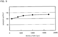
- the magnetic sensor 5 was arranged at the position adjacent to the magnet 4 in the radial direction. Each rotor 2 of these samples is rotated to reach 1000 to 17000 rpm to measure the amplitude of the output voltage of the magnetic sensor 5. Then, the relation between the revolution of the rotor 2 and the amplitude of the output voltage was graphed. The results are shown in FIG. 8 , FIG. 9 and FIG. 25 . It is noted that in these graphs, the output of the magnetic sensor 5 (ordinate) is indicated by the ratio of indices when setting the magnitude of the output at 1000 rpm as 100.
- FIG.8 shows the measurement result of sample 1
- FIG.9 shows the measurement result of sample 2.
- FIG. 25 shows the measurement result of the comparative sample. From FIG. 8 and FIG.9 , it is found that in each of samples 1 and 2 that fall within the scope of the present invention, the output of the magnetic sensor 5 gradually increases as the revolution of the rotor 2 increases. In contrast, as shown in FIG 25 , the comparative sample shows that the output of the magnetic sensor 5 gradually decreases as the revolution of the rotor 2 increases.
- the magnet 4 is attached to the rotor 2 such that the arrangement direction of a pair of magnetic poles is the same as the radial direction of the rotor.
- the magnetic sensor 5 is attached to the housing 3. The magnetism sensing direction of the magnetic sensor 5 is made orthogonal to the radial direction of the rotor.
- the output of the magnetic sensor 5 can remain at a high level even if the rotation speed of the rotor 2 becomes high, which makes it possible to accurately detect the rotation speed of the rotor 2.
- the magnetic sensor 5 of the present embodiment is arranged at a position apart from the magnet 4 by the prescribed distance L in an axial direction (X direction) of the rotor 2.
- part of a magnetic field H generated from the magnet 4 flows inside the housing 3 in the direction orthogonal to the radial direction at the position apart from the magnet 4 in the axial direction. Therefore, when the magnetic sensor 5 is arranged at the position apart from the magnet 4 by the prescribed distance L in the axial direction, the intensity of the magnetic field H of the magnet 4, which acts on the magnetic sensor 5 in the magnetism sensing direction, can be enhanced. Thus, the output of the magnetic sensor 5 can be increased, accordingly the rotation speed of the rotor 2 can be detected accurately.
- the magnetic sensor 5 of the present embodiment is located on the inside than the intermediate position M between the exterior surface 31 and the interior surface 32 of the housing 3 in the radial direction.
- the magnetic sensor 5 can be closer to the magnet 4.
- the output of the magnetic sensor 5 can be increased. Consequently, the rotation speed of the rotor 2 can be detected more accurately.
- the housing 3 of the present embodiment has a recessed part 33 recessively formed inward in the radial direction from the exterior surface 31. And the magnetic sensor 5 is arranged in the recessed part 33.
- the magnetic sensor 5 can be easily disposed inside the housing 3 from the outside of the housing 3. In this way, it becomes possible to readily manufacture the rotary machine 1.
- the magnetic sensor 5 when the magnetic sensor 5 is disposed in the recessed part 33, the magnetic sensor 5 can be made close to the magnet 4. Therefore, the output of the magnetic sensor 5 can be increased to thereby detect the rotation speed of the rotor 2 accurately.
- the rotary machine 1 of the present embodiment is used as a turbocharger 1a.
- the rotor 2 is a compressor wheel 2a of the turbocharger 1
- the housing 3 is a compressor housing 3a for housing the compressor wheel 2a.
- the magnetic sensor 5 is attached to the compressor housing 3a.
- the compressor housing 3a is an intake side housing 3 of a turbocharger 1a
- the temperature is lower than that of a turbine housing 12 that is an exhaust side housing. Therefore, by attaching the magnetic sensor 5 to the compressor housing 3a, the magnetic sensor 5 can be prevented from having a high temperature to thereby prevent shortening of the life of the magnetic sensor 5.
- the magnetic sensor 5 of the present embodiment is an MI sensor.
- An MI sensor is excellent both in sensitivity for detecting magnetism and response speed. Therefore, even in the case of high-speed rotation exceeding 10000 rpm, by using an MI sensor, time variation of the magnetic field of the magnet 4 can be accurately detected, so that the rotation speed of the rotor 2 can be accurately detected.
- the magnet 4 of the present embodiment is attached such that the center coincides with the rotation axis A of the rotor 2.
- the magnet 4 When the magnet 4 is attached to the rotation axis A in such a manner, the magnet 4 is hardly affected by a centrifugal force accompanied with the rotation of the rotor 2. Accordingly, any failure, for example, dropping of the magnet 4 by the centrifugal force, etc. can be prevented.
- the present embodiment can provide a rotary machine in which the output of the magnetic sensor is hardly lowered even if the rotation speed of the rotor becomes high.
- the rotary machine 1 of the present embodiment is the turbocharger 1a, however, the present invention is not limited thereto.
- the rotary machine 1 can also be applied to some other type of turbo, air motor, and the like.
- the magnetism sensing direction of the magnetic sensor 5 is in the axial direction of the rotor 2 (X direction: refer to FIG. 3 ) or Y direction (refer to FIG. 6 ), however, the present invention is not limited to this. As long as the magnetism sensing direction is orthogonal to the radial direction, the same effects can be obtained even when the magnetism sensing direction is in the direction between X direction and Y direction.
- the present embodiment uses the magnet 4 equipped with a pair of magnetic poles, however, the present invention is not limited to this configuration.
- the magnet 4 equipped with two or more pair of magnetic poles can be used. Accordingly, the magnet 4 can be attached to the rotor 2 such that each of plural pairs of magnetic poles is in the radial direction.
- the present embodiment is an example in which the shape of the housing 3 is modified.
- the housing 3 has a through hole 34 formed passing therethrough in the radial direction.
- the magnetic sensor 5 is disposed inside this through hole 34 and is sealed therein by a sealing member 19 such as an epoxy resin, a ceramic adhesive, and the like.
- the magnetic sensor 5 is disposed such that the magnetism sensing direction of the magnetic sensor 5 is in the axial direction (X direction) of the rotor 2, in the same way as in Embodiment 1. Further, the magnetic sensor 5 is located on the inside than an intermediate position M between the exterior surface 31 and the interior surface 32 of the housing 3 in the radial direction.
- the present embodiment has the same configurations and operational effects as those in Embodiment 1.
- the present embodiment is an example in which the arrangement position of the magnetic sensor 5 is modified.
- the magnetic sensor 5 is arranged at a position apart from the magnet 4 by a predetermined distance L in the axial direction (X direction) in the same way as in Embodiment 1.
- the magnetic sensor 5 is located on the side closer to the rotor 2 than the magnet 4 in the X direction.
- the housing 3 has the recessed part 33 formed therein.
- the magnetic sensor 5 is disposed in the recessed part 33.
- the magnetic sensor 5 is located on the inside than the intermediate position M between the exterior surface 31 and the interior surface 32 of the housing 3 in the radial direction.
- the present embodiment has the same configurations and operational effects as those in Embodiment 1.
- the present embodiment is an example in which the arrangement position of the magnetic sensor 5 is modified.
- the magnetic sensor 5 is arranged at the position adjacent to the magnet 4 in the radial direction (the position where the center of the magnetic sensor 5 is located on the straight line SL drawn in the radial direction passing through the magnet 4).
- the magnetic sensor 5 is arranged such that the magnetism sensing direction is in the Y direction.
- part of the magnetic field H generated from the magnet 4 acts on the magnetic sensor 5 in the Y direction, that is, in the magnetism sensing direction.
- the output of the magnetic sensor 5 can be increased. Accordingly, it becomes possible to accurately detect time variation of the magnetic field H of the magnet 4 by the magnetic sensor 5, so that the rotation speed of the rotor 2 can be measured accurately.
- the present embodiment has the same configurations and operational effects as those in Embodiment 1.
- the present embodiment is an example in which the shape of the housing 3 and the attached position of the magnetic sensor 5 are modified. As shown in FIG. 14 , in the present embodiment, the housing 3 does not have the recessed part 33 or the through hole 34 formed therein. In the present embodiment, the magnetic sensor 5 is attached to the interior surface 32 of the housing 3. It is noted that although not shown in the figure, the magnetic sensor 5 may be attached to the exterior surface 31 of the housing 3.
- the present embodiment has the same configurations and operational effects as those in Embodiment 1.
- the present embodiment is a modified example in which the number of the magnetic sensor 5 is changed.
- the rotary machine 1 of the present embodiment includes two magnetic sensors 5, i.e. a first magnetic sensor 5a and a second magnetic sensor 5b.
- the first magnetic sensor 5a is arranged at the position closer to the magnet 4 than the second magnetic sensor 5b is. Therefore, the magnetic field H of the magnet 4 acts on the first magnetic sensor 5a more strongly than on the second magnetic sensor 5b. Accordingly, as shown in FIG 17 , the output intensity of the first magnetic sensor 5a is higher than that of the second magnetic sensor 5b (refer to FIG. 18 ).
- another component that generates a disturbance magnetic field is disposed around the rotary machine 1.
- another component that generates a disturbance magnetic field is provided inside the engine room.
- the disturbance magnetic field is cancelled using the two magnetic sensors 5a and 5b. Specifically, as shown in Fig. 17 and FIG. 18 , an output that results from the disturbance magnetic field (noise component) is generated from each of the magnetic sensors 5a and 5b in the same way.
- the disturbance magnetic field acts on the two magnetic sensors 5a and 5b with the same intensity.
- the noise components output from the magnetic sensors 5a and 5b have nearly the same intensity. Therefore, subtracting the output of the second magnetic sensor 5b from the output of the first magnetic sensor 5a eliminates the noise components, so that the component that resulted from the magnetic field H of the magnet 4 is left as shown in FIG.19 .
- the rotation speed of the rotor 2 is calculated.
- the present embodiment has the same configurations and operational effects as those in Embodiment 1.
- the present embodiment is a modified example in which the arrangement positions of the two magnetic sensors 5a and 5b are changed.
- the magnetic sensors 5a and 5b are arranged such that the first magnetic sensor 5a, the rotation axis A, and the second magnetic sensor 5b form the angle of 90° when viewed from the axial direction (X direction).
- the distance L from each of the magnetic sensors 5a and 5b to the magnet 4 is set equal.
- the amplitudes of the outputs of the magnetic sensors 5a and 5b are equal to each other.
- the output waveform having a certain amplitude obtained by eliminating the noise components that resulted from the disturbance magnetic field can be obtained by calculating the difference between the outputs of the two magnetic sensors 5a and 5b.
- the present embodiment has the same configurations and operational effects as those in Embodiment 1.
- the present embodiment is a modified example in which the arrangement positions of the two magnetic sensors 5a and 5b are changed.
- the magnetic sensors 5a and 5b are arranged such that the first magnetic sensor 5a, the rotation axis A, and the second magnetic sensor 5b form the angle of 180° when viewed from the axial direction (X direction).
- the distance L from each of the magnetic sensors 5a and 5b to the magnet 4 is set equal.
- the amplitudes of the outputs of the magnetic sensors 5a and 5b are equal to each other.
- the phases of the outputs of the magnetic sensors 5a and 5b are deviated from each other by 180°, therefore, by calculating the difference between the outputs of the two magnetic sensors 5a and 5b, the noise components that resulted from the disturbance magnetic field can be eliminated, and at the same time the resulting output after calculation is allowed to have an amplitude twice as large as the original amplitudes of the outputs of the magnetic sensors 5a and 5b. Accordingly, it becomes possible to measure the rotation speed of the rotor 2 more accurately.
- the present embodiment has the same configurations and operational effects as those in Embodiment 6.
Landscapes
- Physics & Mathematics (AREA)
- General Physics & Mathematics (AREA)
- Engineering & Computer Science (AREA)
- Mechanical Engineering (AREA)
- General Engineering & Computer Science (AREA)
Abstract
Description
- The present invention relates to a rotary machine such as a turbocharger.
- As a rotary machine serving as a turbocharger, or the like, a rotary machine that includes a rotor configured to axially rotate around a rotation axis and a housing configured to house the rotor is known (refer to, for example,
Patent Document 1 mentioned below). In this rotary machine, the rotor has a magnet attached thereto so that the rotation speed of the rotor can be measured. The magnet is attached to the rotor such that the arrangement direction of a pair of magnetic poles is the same as the radial direction of the rotor. Further, the rotary machine is provided with a magnetic sensor outside the housing. - When the rotor rotates, the magnet rotates along with this rotation. Thus, a magnetic field acting on the magnetic sensor varies with time, and accordingly an output of the magnetic sensor varies with time. The rotary machine is configured such that the rotation speed of the rotor is detected on the basis of the time variation of the output of the magnetic sensor.
- In recent years, in order that the rotation speed of the rotor can be measured more accurately, researches have been conducted to enhance the output of the magnetic sensor. For this purpose, the magnetic sensor is attached to the housing, and attempts to arrange the magnetic sensor as close as possible to the magnet have been made. In particular, techniques that make it possible to measure the rotation speed accurately with high sensitivity even when the rotation speed is extremely high, have been demanded.
- In the past, it was considered that the magnetic sensor has only to be arranged at the position adjacent to the magnet in the radial direction of the rotor and the magnetic sensitive direction of the magnetic sensor has only to be the same as the radial direction (refer to
FIG. 24 ). It is because it has been considered that such arrangement makes it possible to arrange the magnetic sensor close to the magnet, and at the same time to increase the output of the magnetic sensor because the magnetic field of the magnet acts on the magnetic sensor in the magnetism sensing direction. - Patent Document 1: Japanese Patent No.
5032578 - However, as the result of experiments conducted by the present inventors, it was found that when the abovementioned configuration being adopted, the output of the magnetic sensor is lowered as the rotation speed of the rotor becomes high (refer to
FIG. 25 ). This is considered, by the assumption, to be caused by an eddy current that generates in the housing. In other words, because the housing is formed of a conductive material such as metal or the like, when the magnetic field of the magnet that acts on the housing varies with time by rotation of the magnet, an eddy current generates inside the housing. The lowering of the output of the magnetic sensor is considered to be caused by cancelling out of the magnetic field of the magnet by the magnetic field generated by the eddy current. When the rotation speed of the magnet becomes high, the time variation rate of the magnetic field of the magnet that acts on the housing becomes high. Accordingly, the eddy current increases, and thus the magnetic field of the magnet can be easily cancelled out. For this reason, it can be considered that the output of the magnetic sensor is lowered as the rotation speed becomes high. As mentioned above, there is a possibility that it becomes difficult in some cases for the abovementioned configuration to be applied to rotary machines in which the rotor rotates at extremely high speed. - The present invention has been made in view of such a background, and it is intended to provide a rotary machine in which the output of a magnetic sensor is hardly lowered even if the rotation speed of a rotor becomes high.
- One aspect of the present invention is a rotary machine including:
- a rotor configured to axially rotate around a rotation axis;
- a housing formed of a conductive material and containing the rotor;
- a magnet attached to the rotor such that an arrangement direction of at least a pair of magnetic poles is in a radial direction of the rotor; and
- a magnetic sensor attached to the housing and configured to detect a time variation of a magnetic field generated from the magnet to thereby detect a rotation speed of the rotor,
- wherein the magnetic sensor is arranged on the outside than the magnet in the radial direction, and
- wherein a magnetism sensing direction of the magnetic sensor is orthogonal to the radial direction.
- In the rotary machine, the magnet is attached to the rotor such that the arrangement direction of the pair of magnetic poles is the same as the radial direction of the rotor. In addition, the magnetic sensor is attached to the housing. And, the magnetism sensing direction of the magnetic sensor is set orthogonal to the radial direction.
- As the result of experiments conducted by the present inventors, it was found that if the abovementioned configuration is adopted, the output of the magnetic sensor is hardly lowered even if the rotation speed of the rotor becomes high, and instead the output becomes higher (refer to
FIG. 8 andFIG. 9 ). The reason is considered that the magnetic field of the magnet and the magnetic field caused by the eddy current are not cancelled with each other, and rather intensify each other with being directed in the same direction. This is considered to be the reason why the output of the magnetic sensor becomes high as the rotation speed of the magnet becomes high and the eddy current generate more largely in the housing. For this reason, by means of arranging the magnetic sensor such that the magnetism sensing direction is set orthogonal to the radial direction, the output of the magnetic sensor can remain at a high level even if the rotation speed of the rotor becomes high, to thereby detect the rotation speed of the rotor accurately. - As mentioned above, the present aspect can provide a rotary machine in which the output of the magnetic sensor is hardly lowered even if the rotation speed of the rotor becomes high.
- It is noted that in the present invention, variation of the magnetic field of the magnet is measured by the magnetic sensor. Therefore, cases where the magnetic sensor is attached in such a manner not to measure the magnetic field of the magnet are out of the present invention. For example, in case, as shown in
FIG. 26 , acenter 59 of amagnetic sensor 5 is aligned with acenter 49 of amagnet 4 in the axial direction (X direction), and the magnetism sensing direction of the magnetic sensor 5 (the longitudinal direction of the magnetic sensor 5) is in X direction, the magnetic field of themagnet 4 acts on thecenter 59 of themagnetic sensor 5 with the almost same intensity in the left and right directions. Therefore, the actual magnetic field that acts on themagnetic sensor 5 is made almost zero. Accordingly, the magnetic field of the magnetic 4 cannot be measured, and thus the rotation speed of arotor 2 cannot be measured. Such a manner to attach themagnetic sensor 5 is out of the present invention. - Further, as mentioned above, in the present invention, the magnetism sensing direction of the magnetic sensor is orthogonal to the radial direction. Here, "the magnetism sensing direction is orthogonal to the radial direction" means that the direction (radial direction) parallel to a straight line SL which passes through the magnetic sensor 5 (refer to
FIG. 3 ) and a rotation axis A and is orthogonal to the rotation axis A is orthogonal to the magnetism sensing direction of themagnetic sensor 5. It is noted that "orthogonal" mentioned here is not strictly restricted, and is permitted to have some displacement. Specifically, displacement at the level of ±10°from the orthogonal can be accepted with no problem. -
-
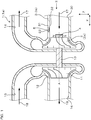
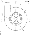
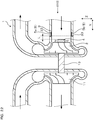
FIG. 1 is a cross-sectional view of a rotary machine according toEmbodiment 1, taken along the line I-I inFIG. 2 . -
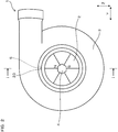
FIG. 2 is an arrow view viewed in the direction of the arrow II inFIG. 1 . -
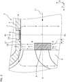
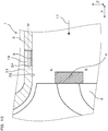
FIG. 3 is an enlarged view of a substantial part ofFIG. 1 . -
FIG. 4 is an arrow view viewed in the direction of the arrow IV inFIG. 3 . -
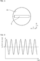
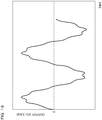
FIG. 5 shows an output waveform of a magnetic sensor according toEmbodiment 1. -
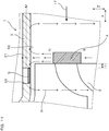
FIG. 6 is a cross-sectional view of the rotary machine according toEmbodiment 1, in which the magnetism sensing direction of the magnetic sensor is in Y direction. -
FIG. 7 is an arrow view viewed in the direction of the arrow VII inFIG. 6 . -
FIG. 8 is a graph showing the relation between the amplitude of output of the magnetic sensor shown inFIG. 3 and the revolution of the rotor. -
FIG. 9 is a graph showing the relation between the amplitude of output of the magnetic sensor shown inFIG. 6 and the revolution of the rotor. -
FIG. 10 is a cross-sectional view of a rotary machine according toEmbodiment 2. -
FIG. 11 is a cross-sectional view of a rotor according toEmbodiment 3. -
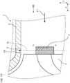
FIG. 12 is a cross-sectional view of a rotor according toEmbodiment 4, taken along the line XII-XII inFIG. 13 . -
FIG. 13 is an arrow view viewed in the direction of the arrow XIII inFIG. 12 . -
FIG. 14 is a cross-sectional view of a rotary machine according toEmbodiment 5. -
FIG. 15 is a cross-sectional view of a rotor according to Embodiment 6, taken along the line XV-XV inFIG. 16 . -
FIG. 16 is an arrow view viewed in the direction of the arrow XVI inFIG. 15 . -
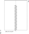
FIG. 17 shows an output waveform of a first magnetic sensor according to Embodiment 6. -
FIG. 18 shows an output waveform of a second magnetic sensor according to Embodiment 6. -
FIG. 19 shows a waveform resulting from subtraction of the output waveform of the second magnetic sensor from the output waveform of the first magnetic sensor in Embodiment 6. -
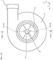
FIG. 20 is a cross-sectional view of a rotary machine according to Embodiment 7, taken along the line XX-XX inFIG. 21 . -
FIG. 21 is an arrow view viewed in the direction of the arrow XXI inFIG. 20 . -
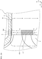
FIG. 22 is a cross-sectional view of a rotary machine according to Embodiment 8, taken along the line XXII-XXII inFIG. 23 . -
FIG. 23 is an arrow view viewed in the direction of the arrow XXIII inFIG. 22 . -
FIG. 24 is a cross-sectional view of a rotary machine according toComparative Embodiment 1. -
FIG. 25 is a graph showing the relation between the amplitude of output of the magnetic sensor shown inFIG. 24 and the revolution of the rotor. -
FIG. 26 is a cross-sectional view of a rotary machine according toComparative Embodiment 2. - The magnetic sensor is preferably arranged at a position apart from the magnet by a prescribed distance in an axial direction of the rotor.
- Part of the magnetic field generated from the magnet flows in the direction orthogonal to the radial direction inside the housing at the position apart from the magnet in the axial direction (refer to
FIG.3 ). Therefore, when the magnetic sensor is arranged at the position apart from the magnet by the prescribed distance in the axial direction, the intensity of the magnetic field of the magnet, which acts on the magnetic sensor in the magnetism sensing direction, can be enhanced. Thus, the output of the magnetic sensor can be increased, accordingly the rotation speed of the rotor can be detected accurately. - Further, the magnetic sensor is preferably located on the inside than an intermediate position between an exterior surface and an interior surface of the housing in the radial direction.
- In this case, the magnetic sensor can be closer to the magnet. Thus, the output of the magnetic sensor can be increased. Accordingly, the rotation speed of the rotor can be detected more accurately.
- Still further, it is preferable that the housing has a recessed part recessively formed inward in the radial direction from the exterior surface of the housing, and the magnetic sensor is arranged in the recessed part.
- In this case, when manufacturing the rotary machine, the magnetic sensor can be easily disposed inside the housing from the outside of the housing. In this way, the rotary machine can be readily manufactured. In addition, when the magnetic sensor is disposed in the recessed part, the magnetic sensor can be arranged close to the magnet. Therefore, the output of the magnetic sensor can be increased to thereby detect the rotation speed of the rotor accurately.
- Still further, it is preferable that two or more of the magnetic sensors are provided, which differ from each other in output corresponding to the magnetic field generated from the magnet so that the difference of outputs between the two magnetic sensors is used to detect the rotation speed of the rotor.
- In this case, it hardly suffers from influence of disturbance magnetic field, so that the rotation speed of the rotor can be measured more accurately. Specifically, even if the disturbance magnetic field acts on the two magnetic sensors from the outside of the rotary machine, the outputs based on this disturbance magnetic field are almost the same between the two magnetic sensors. Therefore, influence of the disturbance magnetic field can be eliminated from the output by calculating the difference between the outputs of the two magnetic sensors. Consequently, it becomes easy to accurately detect the time variation of the magnetic field of the magnet, which makes it possible to detect the rotation speed of the rotor more accurately.
- Still further, it is preferable that the rotary machine is used as a turbocharger, the rotor is a compressor wheel of the turbocharger, the housing is a compressor housing containing the compressor wheel, and the magnetic sensor is attached to the compressor housing.
- In this case, it becomes possible to measure the rotation speed of the compressor wheel accurately. In addition, because the compressor housing is an intake side housing of a turbocharger, the temperature is lower than that of a turbine housing that is an exhaust side housing. Therefore, by attaching the magnetic sensor to the compressor housing, the magnetic sensor can be prevented from having a high temperature to thereby prevent shortening of the life of the magnetic sensor.
- Still further, the magnetic sensor is preferably a magneto-impedance sensor.
- A magneto-impedance sensor (hereinafter, also referred to as an MI sensor) has high sensitivity for detecting magnetism and is also excellent in high-speed response. Therefore, although other-type magnetic sensors also can be used, particularly in the case of high-speed rotation at 10000 rpm or higher, by using an MI sensor, time variation of the magnetic field of the magnet can be accurately detected, so that the rotation speed of the rotor can be accurately detected.
- Still further, the magnet is preferably attached to the rotation axis.
- When the magnet is attached to the rotation axis, the magnet is hardly affected by a centrifugal force accompanied with the rotation of the rotor. Accordingly, any failure, for example, dropping of the magnet by the centrifugal force, etc. can be prevented.
- An embodiment of the rotary machine will be explained with reference to
FIG.1 to FIG. 9 . As shown inFIG. 1 andFIG. 2 , arotary machine 1 of the present embodiment includes arotor 2, ahousing 3, amagnet 4, and amagnetic sensor 5. Therotor 2 axially rotates around a rotation axis A. Thehousing 3 is formed of a conductive material and contains therotor 2. - The
magnet 4 is attached to therotor 2 in such a manner that the arrangement direction of a pair of magnetic poles is in a radial direction of therotor 2. Themagnetic sensor 5 is attached to thehousing 3. Themagnetic sensor 5 detects time variation of the magnetic field generated from themagnet 4. In this way, it is configured to detect rotation speed of therotor 2. - The
magnetic sensor 5 is arranged on the outside than themagnet 4 in the radial direction. - The magnetism sensing direction of the
magnetic sensor 5 is orthogonal to the radial direction. - As shown in
FIG. 1 , therotary machine 1 of the present embodiment is aturbocharger 1a that is to be installed in an engine of a vehicle, and the like. Theturbocharger 1a includes aturbo wheel 11, aturbo housing 12 for housing theturbo wheel 11, aturbo shaft 13, acompressor wheel 2a, acompressor housing 3a for housing thecompressor wheel 2a, anair inlet 30, anair outlet 14, anexhaust air inlet 15, and anexhaust air outlet 16. Theturbo shaft 13 connects theturbo wheel 11 and thecompressor wheel 2a. - The
rotor 2 of the present embodiment is thecompressor wheel 2a of theturbocharger 1a. And, thehousing 3 of the present embodiment is thecompressor housing 3a. Themagnetic sensor 5 is attached to thecompressor housing 3a. Thecompressor housing 3a is made of aluminum. - When
exhaust gas 18 is discharged from the engine not shown in the figure, theturbo wheel 11 rotates. Accompanying the rotation, thecompressor wheel 2a also rotates. Accordingly,air 17 is sucked from theair inlet 30 and fed to the engine. - The
magnet 4 of the present embodiment is attached such that the center coincides with the rotation axis A of thecompressor wheel 2a. Themagnet 4 of the present embodiment is a nut that has been magnetized (magnetized nut). Using this magnetized nut, thecompressor wheel 2a is tightened to theturbo shaft 13. - As shown in
FIG. 3 , themagnetic sensor 5 is arranged at a position apart from themagnet 4 by a prescribed distance L in the axial direction (X direction). Themagnetic sensor 5 of the present embodiment is a magneto-impedance sensor. Thehousing 3 has a recessedpart 33 recessively formed inward in the radial direction from the exterior surface of the housing. Themagnetic sensor 5 is arranged in the recessedpart 33. - As shown in
FIG.3 andFIG. 4 , the magnetism sensing direction of themagnetic sensor 5 is the same as the axial direction. Themagnetic sensor 5 is located on the inside than an intermediate position M between anexterior surface 31 and aninterior surface 32 of thehousing 3 in the radial direction. - When the
rotor 2 rotates, themagnet 4 also rotates. Thus, the magnetic field that is generated from themagnet 4 and acts on thehousing 3 varies with time. Accordingly, as shown inFIG.5 , the output of themagnetic sensor 5 varies with time. It is configured to detect the rotation speed of therotor 2 using the time variation of the output. In the present embodiment, detected values of the rotation speed are transmitted to an ECU that is not shown in the figure. The ECU uses the detected values to control the engine. - Experiments to confirm the effects of the present embodiment were conducted. Firstly, the
rotary machine 1 shown inFIG.1 to FIG. 3 was prepared assample 1 that falls within the scope of the present invention. Further, as shown inFIG. 6 andFIG.7 , therotary machine 1 in which the magnetism sensing direction of themagnetic sensor 5 is in the direction (Y direction) that is orthogonal to both of the axial direction (X direction) and the opening direction of the recessed part 33 (Z direction) was prepared assample 2 that falls within the scope of the present invention. Still further, as shown inFIG.24 , therotary machine 1 in which the magnetism sensing direction of themagnetic sensor 5 is in the radial direction (Z direction) was prepared as a comparative sample that departs from the scope of the present invention. In the comparative sample, themagnetic sensor 5 was arranged at the position adjacent to themagnet 4 in the radial direction. Eachrotor 2 of these samples is rotated to reach 1000 to 17000 rpm to measure the amplitude of the output voltage of themagnetic sensor 5. Then, the relation between the revolution of therotor 2 and the amplitude of the output voltage was graphed. The results are shown inFIG. 8 ,FIG. 9 andFIG. 25 . It is noted that in these graphs, the output of the magnetic sensor 5 (ordinate) is indicated by the ratio of indices when setting the magnitude of the output at 1000 rpm as 100. -
FIG.8 shows the measurement result ofsample 1, andFIG.9 shows the measurement result ofsample 2.FIG. 25 shows the measurement result of the comparative sample. FromFIG. 8 andFIG.9 , it is found that in each ofsamples magnetic sensor 5 gradually increases as the revolution of therotor 2 increases. In contrast, as shown inFIG 25 , the comparative sample shows that the output of themagnetic sensor 5 gradually decreases as the revolution of therotor 2 increases. - Operational effects of the present invention will be explained. As shown in
FIG. 3 andFIG. 6 , in the present embodiment, themagnet 4 is attached to therotor 2 such that the arrangement direction of a pair of magnetic poles is the same as the radial direction of the rotor. And, themagnetic sensor 5 is attached to thehousing 3. The magnetism sensing direction of themagnetic sensor 5 is made orthogonal to the radial direction of the rotor. - According to such a configuration, as shown in
FIG. 8 andFIG. 9 , even if the rotation speed of therotor 2 becomes high, the output of themagnetic sensor 5 is hardly lowered, and instead the output can be made higher. This is considered, by the assumption, because the magnetic field of themagnet 4 and the magnetic field caused by the eddy current generated in thehousing 3 are not cancelled out each other in the direction orthogonal to the radial direction, and rather intensify each other with being directed in the same direction. Therefore, it can be considered that the output of themagnetic sensor 5 becomes high as the rotation speed of themagnet 4 becomes high and the eddy current generate more largely in thehousing 3. For this reason, when themagnetic sensor 5 is arranged such that the magnetism sensing direction is orthogonal to the radial direction as in the present embodiment, the output of themagnetic sensor 5 can remain at a high level even if the rotation speed of therotor 2 becomes high, which makes it possible to accurately detect the rotation speed of therotor 2. - Further, as shown in
FIG. 3 , themagnetic sensor 5 of the present embodiment is arranged at a position apart from themagnet 4 by the prescribed distance L in an axial direction (X direction) of therotor 2. - As shown in
FIG.3 , part of a magnetic field H generated from themagnet 4 flows inside thehousing 3 in the direction orthogonal to the radial direction at the position apart from themagnet 4 in the axial direction. Therefore, when themagnetic sensor 5 is arranged at the position apart from themagnet 4 by the prescribed distance L in the axial direction, the intensity of the magnetic field H of themagnet 4, which acts on themagnetic sensor 5 in the magnetism sensing direction, can be enhanced. Thus, the output of themagnetic sensor 5 can be increased, accordingly the rotation speed of therotor 2 can be detected accurately. - Further, as shown in
FIG.3 , themagnetic sensor 5 of the present embodiment is located on the inside than the intermediate position M between theexterior surface 31 and theinterior surface 32 of thehousing 3 in the radial direction. - According to such a configuration, the
magnetic sensor 5 can be closer to themagnet 4. Thus, the output of themagnetic sensor 5 can be increased. Consequently, the rotation speed of therotor 2 can be detected more accurately. - Still further, as shown in
FIG. 3 , thehousing 3 of the present embodiment has a recessedpart 33 recessively formed inward in the radial direction from theexterior surface 31. And themagnetic sensor 5 is arranged in the recessedpart 33. - Therefore, when manufacturing the
rotary machine 1, themagnetic sensor 5 can be easily disposed inside thehousing 3 from the outside of thehousing 3. In this way, it becomes possible to readily manufacture therotary machine 1. In addition, when themagnetic sensor 5 is disposed in the recessedpart 33, themagnetic sensor 5 can be made close to themagnet 4. Therefore, the output of themagnetic sensor 5 can be increased to thereby detect the rotation speed of therotor 2 accurately. - Still further, as shown in
FIG. 1 , therotary machine 1 of the present embodiment is used as aturbocharger 1a. Therotor 2 is acompressor wheel 2a of theturbocharger 1, thehousing 3 is acompressor housing 3a for housing thecompressor wheel 2a. Themagnetic sensor 5 is attached to thecompressor housing 3a. - Thus, it becomes possible to measure the rotation speed of the
compressor wheel 2a accurately. In addition, because thecompressor housing 3a is anintake side housing 3 of aturbocharger 1a, the temperature is lower than that of aturbine housing 12 that is an exhaust side housing. Therefore, by attaching themagnetic sensor 5 to thecompressor housing 3a, themagnetic sensor 5 can be prevented from having a high temperature to thereby prevent shortening of the life of themagnetic sensor 5. - Still further, the
magnetic sensor 5 of the present embodiment is an MI sensor. - An MI sensor is excellent both in sensitivity for detecting magnetism and response speed. Therefore, even in the case of high-speed rotation exceeding 10000 rpm, by using an MI sensor, time variation of the magnetic field of the
magnet 4 can be accurately detected, so that the rotation speed of therotor 2 can be accurately detected. - Still further, as shown in
FIG. 1 , themagnet 4 of the present embodiment is attached such that the center coincides with the rotation axis A of therotor 2. - When the
magnet 4 is attached to the rotation axis A in such a manner, themagnet 4 is hardly affected by a centrifugal force accompanied with the rotation of therotor 2. Accordingly, any failure, for example, dropping of themagnet 4 by the centrifugal force, etc. can be prevented. - As mentioned above, the present embodiment can provide a rotary machine in which the output of the magnetic sensor is hardly lowered even if the rotation speed of the rotor becomes high.
- It is noted that the
rotary machine 1 of the present embodiment is theturbocharger 1a, however, the present invention is not limited thereto. For example, therotary machine 1 can also be applied to some other type of turbo, air motor, and the like. In addition, in the present embodiment, the magnetism sensing direction of themagnetic sensor 5 is in the axial direction of the rotor 2 (X direction: refer toFIG. 3 ) or Y direction (refer toFIG. 6 ), however, the present invention is not limited to this. As long as the magnetism sensing direction is orthogonal to the radial direction, the same effects can be obtained even when the magnetism sensing direction is in the direction between X direction and Y direction. - Still further, the present embodiment uses the
magnet 4 equipped with a pair of magnetic poles, however, the present invention is not limited to this configuration. In other words, themagnet 4 equipped with two or more pair of magnetic poles can be used. Accordingly, themagnet 4 can be attached to therotor 2 such that each of plural pairs of magnetic poles is in the radial direction. - In the following embodiments, the reference numbers which are used in the figures and are the same as were used in
Embodiment 1 indicate the same structural elements, etc. as were used inEmbodiment 1, except as otherwise shown. - The present embodiment is an example in which the shape of the
housing 3 is modified. As shown inFIG. 10 , in the present embodiment, thehousing 3 has a throughhole 34 formed passing therethrough in the radial direction. And, themagnetic sensor 5 is disposed inside this throughhole 34 and is sealed therein by a sealingmember 19 such as an epoxy resin, a ceramic adhesive, and the like. - In the present embodiment, the
magnetic sensor 5 is disposed such that the magnetism sensing direction of themagnetic sensor 5 is in the axial direction (X direction) of therotor 2, in the same way as inEmbodiment 1. Further, themagnetic sensor 5 is located on the inside than an intermediate position M between theexterior surface 31 and theinterior surface 32 of thehousing 3 in the radial direction. - In addition, the present embodiment has the same configurations and operational effects as those in
Embodiment 1. - The present embodiment is an example in which the arrangement position of the
magnetic sensor 5 is modified. As shown inFIG. 11 , in the present embodiment, themagnetic sensor 5 is arranged at a position apart from themagnet 4 by a predetermined distance L in the axial direction (X direction) in the same way as inEmbodiment 1. Themagnetic sensor 5 is located on the side closer to therotor 2 than themagnet 4 in the X direction. - In addition, the
housing 3 has the recessedpart 33 formed therein. Themagnetic sensor 5 is disposed in the recessedpart 33. Themagnetic sensor 5 is located on the inside than the intermediate position M between theexterior surface 31 and theinterior surface 32 of thehousing 3 in the radial direction. - Also in the case configured as mentioned above, it becomes easy for the magnetic field H of the
magnet 4 to act on themagnetic sensor 5 in the magnetism sensing direction in the same way as inEmbodiment 1. Therefore, the output of themagnetic sensor 5 can be increased. - In addition, the present embodiment has the same configurations and operational effects as those in
Embodiment 1. - The present embodiment is an example in which the arrangement position of the
magnetic sensor 5 is modified. As shown inFIG. 12 andFIG. 13 , in the present embodiment, themagnetic sensor 5 is arranged at the position adjacent to themagnet 4 in the radial direction (the position where the center of themagnetic sensor 5 is located on the straight line SL drawn in the radial direction passing through the magnet 4). Themagnetic sensor 5 is arranged such that the magnetism sensing direction is in the Y direction. - As shown in
FIG. 13 , part of the magnetic field H generated from themagnet 4 acts on themagnetic sensor 5 in the Y direction, that is, in the magnetism sensing direction. Thus, the output of themagnetic sensor 5 can be increased. Accordingly, it becomes possible to accurately detect time variation of the magnetic field H of themagnet 4 by themagnetic sensor 5, so that the rotation speed of therotor 2 can be measured accurately. - Here, as shown in
FIG. 26 , in case themagnetic sensor 5 is arranged at the position adjacent to themagnet 4 in the radial direction and the magnetism sensing direction of themagnetic sensor 5 is set in the X direction, magnetism generated from themagnet 4 acts on thecenter 59 of themagnetic sensor 5 with the same intensity in the left and right directions, and thus the output of themagnetic sensor 5 is lowered, which is undesirable and requires attention. - In addition, the present embodiment has the same configurations and operational effects as those in
Embodiment 1. - The present embodiment is an example in which the shape of the
housing 3 and the attached position of themagnetic sensor 5 are modified. As shown inFIG. 14 , in the present embodiment, thehousing 3 does not have the recessedpart 33 or the throughhole 34 formed therein. In the present embodiment, themagnetic sensor 5 is attached to theinterior surface 32 of thehousing 3. It is noted that although not shown in the figure, themagnetic sensor 5 may be attached to theexterior surface 31 of thehousing 3. - In addition, the present embodiment has the same configurations and operational effects as those in
Embodiment 1. - The present embodiment is a modified example in which the number of the
magnetic sensor 5 is changed. As shown inFIG. 15 andFIG. 16 , therotary machine 1 of the present embodiment includes twomagnetic sensors 5, i.e. a firstmagnetic sensor 5a and a secondmagnetic sensor 5b. The firstmagnetic sensor 5a is arranged at the position closer to themagnet 4 than the secondmagnetic sensor 5b is. Therefore, the magnetic field H of themagnet 4 acts on the firstmagnetic sensor 5a more strongly than on the secondmagnetic sensor 5b. Accordingly, as shown inFIG 17 , the output intensity of the firstmagnetic sensor 5a is higher than that of the secondmagnetic sensor 5b (refer toFIG. 18 ). - In some cases, another component that generates a disturbance magnetic field is disposed around the
rotary machine 1. For example, when therotary machine 1 is applied to a turbocharger, another component that generates a disturbance magnetic field is provided inside the engine room. When themagnetic sensor 5 suffers from influence of the disturbance magnetic field, there occurs a possibility that the rotation speed of therotor 2 cannot be measured with satisfactory accuracy. So, in the present embodiment, the disturbance magnetic field is cancelled using the twomagnetic sensors Fig. 17 andFIG. 18 , an output that results from the disturbance magnetic field (noise component) is generated from each of themagnetic sensors magnetic sensors magnetic sensors magnetic sensors magnetic sensor 5b from the output of the firstmagnetic sensor 5a eliminates the noise components, so that the component that resulted from the magnetic field H of themagnet 4 is left as shown inFIG.19 . In the present embodiment, by using this value, the rotation speed of therotor 2 is calculated. - Operational effects of the present embodiment will be explained. According to the abovementioned configuration, it is possible to leave the output based on the magnetic field of the
magnet 4 from the outputs of themagnetic sensors rotor 2 can be measured more accurately. - In addition, the present embodiment has the same configurations and operational effects as those in
Embodiment 1. - The present embodiment is a modified example in which the arrangement positions of the two
magnetic sensors FIG. 21 , in the present embodiment, themagnetic sensors magnetic sensor 5a, the rotation axis A, and the secondmagnetic sensor 5b form the angle of 90° when viewed from the axial direction (X direction). And, as shown inFIG. 20 , in the X direction, the distance L from each of themagnetic sensors magnet 4 is set equal. - Thus configured, because the distance L from the
magnet 4 is equal between themagnetic sensors magnetic sensors magnetic sensors magnetic sensors rotor 2 can be accurately calculated. - In addition, the present embodiment has the same configurations and operational effects as those in
Embodiment 1. - The present embodiment is a modified example in which the arrangement positions of the two
magnetic sensors FIG. 23 , in the present embodiment, themagnetic sensors magnetic sensor 5a, the rotation axis A, and the secondmagnetic sensor 5b form the angle of 180° when viewed from the axial direction (X direction). And, as shown inFIG. 22 , in the X direction, the distance L from each of themagnetic sensors magnet 4 is set equal. - Thus configured, because the distance L from the
magnet 4 is equal between themagnetic sensors magnetic sensors magnetic sensors magnetic sensors magnetic sensors rotor 2 more accurately. - In addition, the present embodiment has the same configurations and operational effects as those in Embodiment 6.
Claims (8)
- A rotary machine comprising:a rotor configured to axially rotate around a rotation axis;a housing formed of a conductive material and containing the rotor;a magnet attached to the rotor such that an arrangement direction of at least a pair of magnetic poles is in a radial direction of the rotor; anda magnetic sensor attached to the housing and configured to detect a time variation of a magnetic field generated from the magnet to thereby detect a rotation speed of the rotor,wherein the magnetic sensor is arranged on the outside than the magnet in the radial direction, andwherein a magnetism sensing direction of the magnetic sensor is orthogonal to the radial direction.
- The rotary machine according to claim 1, wherein the magnetic sensor is arranged at a position apart from the magnet by a prescribed distance in an axial direction of the rotor.
- The rotary machine according to claim 1 or 2, wherein the magnetic sensor is located on the inside than an intermediate position between an exterior surface and an interior surface of the housing in the radial direction.
- The rotary machine according to any one of claims 1 to 3, wherein the housing has a recessed part recessively formed inward in the radial direction from the exterior surface of the housing, and the magnetic sensor is arranged in the recessed part.
- The rotary machine according to any one of claims 1 to 4, wherein two or more of the magnetic sensors are provided, which differ from each other in output corresponding to the magnetic field generated from the magnet so that the difference of outputs between the two magnetic sensors is used to detect the rotation speed of the rotor.
- The rotary machine according to any one of claims 1 to 5, wherein the rotary machine is used as a turbocharger, the rotor is a compressor wheel of the turbocharger, the housing is a compressor housing containing the compressor wheel, and the magnetic sensor is attached to the compressor housing.
- The rotary machine according to any one of claims 1 to 6, wherein the magnetic sensor is a magneto-impedance sensor.
- The rotary machine according to any one of claims 1 to 7, wherein the magnet is attached to the rotation axis.
Applications Claiming Priority (2)
| Application Number | Priority Date | Filing Date | Title |
|---|---|---|---|
| JP2016114992A JP6233455B1 (en) | 2016-06-09 | 2016-06-09 | Rotating machine |
| PCT/JP2017/020330 WO2017213004A1 (en) | 2016-06-09 | 2017-05-31 | Rotary machine |
Publications (2)
| Publication Number | Publication Date |
|---|---|
| EP3447501A1 true EP3447501A1 (en) | 2019-02-27 |
| EP3447501A4 EP3447501A4 (en) | 2019-07-31 |
Family
ID=60417511
Family Applications (1)
| Application Number | Title | Priority Date | Filing Date |
|---|---|---|---|
| EP17810182.0A Withdrawn EP3447501A4 (en) | 2016-06-09 | 2017-05-31 | ROTARY MACHINE |
Country Status (4)
| Country | Link |
|---|---|
| US (1) | US10900988B2 (en) |
| EP (1) | EP3447501A4 (en) |
| JP (1) | JP6233455B1 (en) |
| WO (1) | WO2017213004A1 (en) |
Families Citing this family (5)
| Publication number | Priority date | Publication date | Assignee | Title |
|---|---|---|---|---|
| JP6840970B2 (en) * | 2016-09-21 | 2021-03-10 | 日立金属株式会社 | Turbocharger with rotation speed detector |
| JP6926502B2 (en) * | 2017-02-10 | 2021-08-25 | 日立金属株式会社 | Rotation sensor for turbo and turbocharger |
| JP7054449B2 (en) * | 2018-05-25 | 2022-04-14 | 日立金属株式会社 | Rotation sensor for turbo |
| US10895583B2 (en) * | 2018-05-25 | 2021-01-19 | Hitachi Metals, Ltd. | Turbo rotation sensor |
| EP3825657A1 (en) * | 2019-11-22 | 2021-05-26 | Berlin Heart GmbH | Rotary machine with sensorless rotor position detection |
Family Cites Families (20)
| Publication number | Priority date | Publication date | Assignee | Title |
|---|---|---|---|---|
| JPS5032578B1 (en) | 1969-05-30 | 1975-10-22 | ||
| DE3122376A1 (en) * | 1981-06-05 | 1982-12-23 | Robert Bosch Gmbh, 7000 Stuttgart | DEVICE FOR DETECTING THE SPEED OF ROTATING PARTS |
| JPS63136945A (en) * | 1986-11-27 | 1988-06-09 | Toshiba Corp | Motor |
| EP0606942A1 (en) | 1993-01-15 | 1994-07-20 | Magnavox Electronic Systems Company | Angular speed and position measuring device and method |
| US5602472A (en) | 1993-01-15 | 1997-02-11 | Hughes Electronics | Apparatus and method for determining angular position and rotational speed using a rotating magnet and a directional magnetometer |
| US5670877A (en) | 1994-12-05 | 1997-09-23 | Hughes Electronics | Shaft rotation sensor with magnetic sensors angularly spaced apart with respect to a magnetic source |
| EP0807256B1 (en) * | 1995-02-02 | 2001-07-04 | Siemens Aktiengesellschaft | Device for measuring the rotation speed or detecting the direction of rotation of a rotary magnetic field |
| US6124709A (en) * | 1998-06-05 | 2000-09-26 | Cts Corporation | Magnetic position sensor having a variable width magnet mounted into a rotating disk and a hall effect sensor |
| US6265867B1 (en) | 1999-05-19 | 2001-07-24 | Arthur D. Little, Inc. | Position encoder utilizing fluxgate sensors |
| US6483296B1 (en) * | 1999-06-17 | 2002-11-19 | Denso Corporation | Angular position detection apparatus |
| US6919657B2 (en) * | 2003-10-10 | 2005-07-19 | Sunonwealth Electric Machine Industry Co., Ltd. | Combination structure of a motor |
| DE102005010921A1 (en) * | 2004-07-15 | 2006-02-09 | Siemens Ag | turbocharger |
| JP2006058274A (en) * | 2004-08-20 | 2006-03-02 | Aec:Kk | Sensing sensor |
| DE102005029764B4 (en) * | 2005-06-27 | 2010-11-11 | Continental Automotive France | Sensor for measuring the speed of a turbo shaft |
| DE102006003599A1 (en) | 2006-01-25 | 2007-08-16 | Siemens Ag | Compressor housing for an exhaust gas turbocharger |
| DE102006040667B3 (en) | 2006-08-30 | 2008-01-10 | Siemens Ag | Waste gate actuator for an exhaust gas turbocharger |
| CN101939623B (en) | 2008-02-07 | 2013-10-09 | 日立金属株式会社 | Rotation angle detection device, rotating machine and rotation angle detection method |
| JP5705705B2 (en) * | 2011-11-11 | 2015-04-22 | 日立オートモティブシステムズ株式会社 | Magnetic angle measuring device and rotating machine using the same |
| US10408892B2 (en) * | 2013-07-19 | 2019-09-10 | Allegro Microsystems, Llc | Magnet with opposing directions of magnetization for a magnetic sensor |
| JP5886269B2 (en) * | 2013-12-27 | 2016-03-16 | マブチモーター株式会社 | Rotation detection device and motor |
-
2016
- 2016-06-09 JP JP2016114992A patent/JP6233455B1/en not_active Expired - Fee Related
-
2017
- 2017-05-31 EP EP17810182.0A patent/EP3447501A4/en not_active Withdrawn
- 2017-05-31 WO PCT/JP2017/020330 patent/WO2017213004A1/en not_active Ceased
- 2017-05-31 US US16/306,789 patent/US10900988B2/en not_active Expired - Fee Related
Also Published As
| Publication number | Publication date |
|---|---|
| JP2017219455A (en) | 2017-12-14 |
| JP6233455B1 (en) | 2017-11-22 |
| US20190137536A1 (en) | 2019-05-09 |
| WO2017213004A1 (en) | 2017-12-14 |
| EP3447501A4 (en) | 2019-07-31 |
| US10900988B2 (en) | 2021-01-26 |
Similar Documents
| Publication | Publication Date | Title |
|---|---|---|
| US10900988B2 (en) | Rotary machine | |
| US6323641B1 (en) | Non-contacting position sensor with helical flux linkage | |
| US20050122095A1 (en) | Rotation sensor and method | |
| US20150308859A1 (en) | method for monitoring a rotation of a compressor wheel | |
| US9470554B2 (en) | Position detector | |
| US20170115320A1 (en) | Magnetic sensing system and method for detecting shaft speed | |
| EP3221678B1 (en) | Temperature and angular speed sensing apparatus | |
| US20150233735A1 (en) | Sensor device for acquiring at least one rotational property of a rotating element | |
| US20140340081A1 (en) | Magnetic sensor | |
| EP2088398B1 (en) | Rotation angle detector | |
| US20060267581A1 (en) | Angle position sensor | |
| CA2873702A1 (en) | Battery-free meter for flowing media | |
| US7019517B2 (en) | Offset magnet rotary position sensor | |
| US20090319120A1 (en) | Vehicle steering angle sensor | |
| US6404185B1 (en) | Apparatus and method for sensing an angular position of a flux linkage member | |
| US10408854B2 (en) | Sensor arrangement for measuring the rate of rotation of a rotating component | |
| US10487680B2 (en) | Turbo rotation sensor and turbocharger | |
| US20150110650A1 (en) | Exhaust-gas turbocharger | |
| JP6344590B2 (en) | Turbocharger | |
| AU2010305079A1 (en) | Measuring device for detecting rotation signals | |
| JP2018048883A (en) | Turbocharger attached with rotary velocity detection device | |
| JP6489032B2 (en) | Turbo rotation sensor and turbocharger | |
| JP5831689B2 (en) | Rotation angle detection device and method | |
| JP6452060B1 (en) | Turbocharger | |
| JP6493821B2 (en) | Turbocharger |
Legal Events
| Date | Code | Title | Description |
|---|---|---|---|
| STAA | Information on the status of an ep patent application or granted ep patent |
Free format text: STATUS: THE INTERNATIONAL PUBLICATION HAS BEEN MADE |
|
| PUAI | Public reference made under article 153(3) epc to a published international application that has entered the european phase |
Free format text: ORIGINAL CODE: 0009012 |
|
| STAA | Information on the status of an ep patent application or granted ep patent |
Free format text: STATUS: REQUEST FOR EXAMINATION WAS MADE |
|
| 17P | Request for examination filed |
Effective date: 20181122 |
|
| AK | Designated contracting states |
Kind code of ref document: A1 Designated state(s): AL AT BE BG CH CY CZ DE DK EE ES FI FR GB GR HR HU IE IS IT LI LT LU LV MC MK MT NL NO PL PT RO RS SE SI SK SM TR |
|
| AX | Request for extension of the european patent |
Extension state: BA ME |
|
| RIC1 | Information provided on ipc code assigned before grant |
Ipc: G01P 1/02 20060101ALI20190329BHEP Ipc: G01P 1/00 20060101ALI20190329BHEP Ipc: G01P 3/487 20060101AFI20190329BHEP |
|
| A4 | Supplementary search report drawn up and despatched |
Effective date: 20190703 |
|
| RIC1 | Information provided on ipc code assigned before grant |
Ipc: G01P 1/00 20060101ALI20190627BHEP Ipc: G01P 3/487 20060101AFI20190627BHEP Ipc: G01P 1/02 20060101ALI20190627BHEP |
|
| DAV | Request for validation of the european patent (deleted) | ||
| DAX | Request for extension of the european patent (deleted) | ||
| STAA | Information on the status of an ep patent application or granted ep patent |
Free format text: STATUS: EXAMINATION IS IN PROGRESS |
|
| 17Q | First examination report despatched |
Effective date: 20210125 |
|
| GRAP | Despatch of communication of intention to grant a patent |
Free format text: ORIGINAL CODE: EPIDOSNIGR1 |
|
| STAA | Information on the status of an ep patent application or granted ep patent |
Free format text: STATUS: GRANT OF PATENT IS INTENDED |
|
| INTG | Intention to grant announced |
Effective date: 20220314 |
|
| STAA | Information on the status of an ep patent application or granted ep patent |
Free format text: STATUS: THE APPLICATION IS DEEMED TO BE WITHDRAWN |
|
| 18D | Application deemed to be withdrawn |
Effective date: 20220726 |