EP3447430A1 - Heat exchanger - Google Patents
Heat exchanger Download PDFInfo
- Publication number
- EP3447430A1 EP3447430A1 EP17785703.4A EP17785703A EP3447430A1 EP 3447430 A1 EP3447430 A1 EP 3447430A1 EP 17785703 A EP17785703 A EP 17785703A EP 3447430 A1 EP3447430 A1 EP 3447430A1
- Authority
- EP
- European Patent Office
- Prior art keywords
- heat transfer
- standing
- standing portions
- transfer fins
- notch
- Prior art date
- Legal status (The legal status is an assumption and is not a legal conclusion. Google has not performed a legal analysis and makes no representation as to the accuracy of the status listed.)
- Granted
Links
Images



Classifications
-
- F—MECHANICAL ENGINEERING; LIGHTING; HEATING; WEAPONS; BLASTING
- F28—HEAT EXCHANGE IN GENERAL
- F28F—DETAILS OF HEAT-EXCHANGE AND HEAT-TRANSFER APPARATUS, OF GENERAL APPLICATION
- F28F1/00—Tubular elements; Assemblies of tubular elements
- F28F1/10—Tubular elements and assemblies thereof with means for increasing heat-transfer area, e.g. with fins, with projections, with recesses
- F28F1/12—Tubular elements and assemblies thereof with means for increasing heat-transfer area, e.g. with fins, with projections, with recesses the means being only outside the tubular element
- F28F1/24—Tubular elements and assemblies thereof with means for increasing heat-transfer area, e.g. with fins, with projections, with recesses the means being only outside the tubular element and extending transversely
- F28F1/32—Tubular elements and assemblies thereof with means for increasing heat-transfer area, e.g. with fins, with projections, with recesses the means being only outside the tubular element and extending transversely the means having portions engaging further tubular elements
- F28F1/325—Fins with openings
-
- F—MECHANICAL ENGINEERING; LIGHTING; HEATING; WEAPONS; BLASTING
- F25—REFRIGERATION OR COOLING; COMBINED HEATING AND REFRIGERATION SYSTEMS; HEAT PUMP SYSTEMS; MANUFACTURE OR STORAGE OF ICE; LIQUEFACTION SOLIDIFICATION OF GASES
- F25B—REFRIGERATION MACHINES, PLANTS OR SYSTEMS; COMBINED HEATING AND REFRIGERATION SYSTEMS; HEAT PUMP SYSTEMS
- F25B39/00—Evaporators; Condensers
-
- F—MECHANICAL ENGINEERING; LIGHTING; HEATING; WEAPONS; BLASTING
- F28—HEAT EXCHANGE IN GENERAL
- F28D—HEAT-EXCHANGE APPARATUS, NOT PROVIDED FOR IN ANOTHER SUBCLASS, IN WHICH THE HEAT-EXCHANGE MEDIA DO NOT COME INTO DIRECT CONTACT
- F28D1/00—Heat-exchange apparatus having stationary conduit assemblies for one heat-exchange medium only, the media being in contact with different sides of the conduit wall, in which the other heat-exchange medium is a large body of fluid, e.g. domestic or motor car radiators
- F28D1/02—Heat-exchange apparatus having stationary conduit assemblies for one heat-exchange medium only, the media being in contact with different sides of the conduit wall, in which the other heat-exchange medium is a large body of fluid, e.g. domestic or motor car radiators with heat-exchange conduits immersed in the body of fluid
- F28D1/04—Heat-exchange apparatus having stationary conduit assemblies for one heat-exchange medium only, the media being in contact with different sides of the conduit wall, in which the other heat-exchange medium is a large body of fluid, e.g. domestic or motor car radiators with heat-exchange conduits immersed in the body of fluid with tubular conduits
- F28D1/053—Heat-exchange apparatus having stationary conduit assemblies for one heat-exchange medium only, the media being in contact with different sides of the conduit wall, in which the other heat-exchange medium is a large body of fluid, e.g. domestic or motor car radiators with heat-exchange conduits immersed in the body of fluid with tubular conduits the conduits being straight
- F28D1/0535—Heat-exchange apparatus having stationary conduit assemblies for one heat-exchange medium only, the media being in contact with different sides of the conduit wall, in which the other heat-exchange medium is a large body of fluid, e.g. domestic or motor car radiators with heat-exchange conduits immersed in the body of fluid with tubular conduits the conduits being straight the conduits having a non-circular cross-section
- F28D1/05366—Assemblies of conduits connected to common headers, e.g. core type radiators
-
- F—MECHANICAL ENGINEERING; LIGHTING; HEATING; WEAPONS; BLASTING
- F28—HEAT EXCHANGE IN GENERAL
- F28F—DETAILS OF HEAT-EXCHANGE AND HEAT-TRANSFER APPARATUS, OF GENERAL APPLICATION
- F28F1/00—Tubular elements; Assemblies of tubular elements
- F28F1/02—Tubular elements of cross-section which is non-circular
-
- F—MECHANICAL ENGINEERING; LIGHTING; HEATING; WEAPONS; BLASTING
- F28—HEAT EXCHANGE IN GENERAL
- F28F—DETAILS OF HEAT-EXCHANGE AND HEAT-TRANSFER APPARATUS, OF GENERAL APPLICATION
- F28F1/00—Tubular elements; Assemblies of tubular elements
- F28F1/02—Tubular elements of cross-section which is non-circular
- F28F1/022—Tubular elements of cross-section which is non-circular with multiple channels
-
- F—MECHANICAL ENGINEERING; LIGHTING; HEATING; WEAPONS; BLASTING
- F28—HEAT EXCHANGE IN GENERAL
- F28F—DETAILS OF HEAT-EXCHANGE AND HEAT-TRANSFER APPARATUS, OF GENERAL APPLICATION
- F28F1/00—Tubular elements; Assemblies of tubular elements
- F28F1/10—Tubular elements and assemblies thereof with means for increasing heat-transfer area, e.g. with fins, with projections, with recesses
- F28F1/12—Tubular elements and assemblies thereof with means for increasing heat-transfer area, e.g. with fins, with projections, with recesses the means being only outside the tubular element
- F28F1/24—Tubular elements and assemblies thereof with means for increasing heat-transfer area, e.g. with fins, with projections, with recesses the means being only outside the tubular element and extending transversely
- F28F1/32—Tubular elements and assemblies thereof with means for increasing heat-transfer area, e.g. with fins, with projections, with recesses the means being only outside the tubular element and extending transversely the means having portions engaging further tubular elements
-
- F—MECHANICAL ENGINEERING; LIGHTING; HEATING; WEAPONS; BLASTING
- F28—HEAT EXCHANGE IN GENERAL
- F28D—HEAT-EXCHANGE APPARATUS, NOT PROVIDED FOR IN ANOTHER SUBCLASS, IN WHICH THE HEAT-EXCHANGE MEDIA DO NOT COME INTO DIRECT CONTACT
- F28D21/00—Heat-exchange apparatus not covered by any of the groups F28D1/00 - F28D20/00
- F28D2021/0019—Other heat exchangers for particular applications; Heat exchange systems not otherwise provided for
- F28D2021/0068—Other heat exchangers for particular applications; Heat exchange systems not otherwise provided for for refrigerant cycles
-
- F—MECHANICAL ENGINEERING; LIGHTING; HEATING; WEAPONS; BLASTING
- F28—HEAT EXCHANGE IN GENERAL
- F28F—DETAILS OF HEAT-EXCHANGE AND HEAT-TRANSFER APPARATUS, OF GENERAL APPLICATION
- F28F17/00—Removing ice or water from heat-exchange apparatus
- F28F17/005—Means for draining condensates from heat exchangers, e.g. from evaporators
-
- F—MECHANICAL ENGINEERING; LIGHTING; HEATING; WEAPONS; BLASTING
- F28—HEAT EXCHANGE IN GENERAL
- F28F—DETAILS OF HEAT-EXCHANGE AND HEAT-TRANSFER APPARATUS, OF GENERAL APPLICATION
- F28F2215/00—Fins
- F28F2215/12—Fins with U-shaped slots for laterally inserting conduits
Definitions
- the present invention relates to a heat exchanger, more particularly, to a heat exchanger used for exchanging heat between air and refrigerant.
- Patent Literature 1 Japanese Patent Unexamined Publication 2012-163318
- Patent Literature 1 Japanese Patent Unexamined Publication 2012-163318
- the flat tubes are thin and hence notches in the flat tubes are small. Because of this, part of the heat transfer fin is lanced and raised and used as a spacer for securing a gap between adjacent heat transfer fins.
- a heat exchanger is a heat exchanger including a plurality of flat tubes that each have a cross-sectional shape perpendicular to a direction of flow of refrigerant with a width direction that extends in an air flow direction; and a plurality of heat transfer fins each having a plurality of notches configured to receive the plurality of flat tubes, the plurality of notches being along the width direction of the plurality of flat tubes, in which the plurality of heat transfer fins includes at least three standing portions provided on a peripheral portion of each of the plurality of notches for forming gaps between adjacent heat transfer fins, and the at least three standing portions are arranged so as not to face each other across a reference line that extends in the width direction through a perpendicular center portion of the flat tube.
- the standing portions are arranged so as not to face each other across the reference line that extends in the width direction through the perpendicular center portion of the flat tube, sufficient standing height of the standing portion can be ensured and fin pitch can be maintained by the standing portions.
- the positional relationship between adjacent heat transfer fins can be stabilized, and strength of the brazed heat transfer fins can be stably secured.
- a heat exchanger according to a second aspect of the present invention is the heat exchanger according to the first aspect, in which each of the plurality of heat transfer fins includes, in the notch, a plurality of the standing portions on each of two long sides that face each other across the reference line.
- a plurality of standing portions is provided on each long side of the notch, and hence stability can be improved when the plurality of heat transfer fins are stacked.
- a heat exchanger according to a third aspect of the present invention is the heat exchanger according to the second aspect of the present invention, in which, in each of the plurality of heat transfer fins, the standing portions on the two long sides of the notches are alternately arranged along the reference line.
- the standing portions on the two long sides are alternately arranged along the reference line, the standing portions can be made taller and a range compatible with a thickness direction of the flat tube perpendicular to the width direction of the flat tube can be expanded to include a thin flat tube.
- a heat exchanger according to a fourth aspect of the present invention is the heat exchanger according to the third aspect, in which, in each of the plurality of heat transfer fins, the standing portions on the two long sides of the notch each form a wave-shape such that the standing portions can be fitted into one another when pushed down into the notch.
- the standing portions on the two long sides each form a wave-shape such that the standing portions can be fitted into one another when pushed down into the notch, the height of the wave-shaped standing portions until the crest portions can be increased, and the member notched with the notch can be utilized to the fullest extent.
- a heat exchanger according to a fifth aspect of the present invention is the heat exchanger according to the second aspect, in which, in each of the plurality of heat transfer fins, each of the plurality of standing portions on each of the long sides forms a wave-shape.
- the standing portions form the wave-shape
- the crest portions of the wave-shaped standing portions on one long side can be made to correspond to the trough portions of the wave-shaped standing portions on the other long side, and hence a plurality of standing portions can easily be made taller.
- a heat exchanger is the heat exchanger according to the fifth aspect, in which, in each of the plurality of heat transfer fins, a distance from a wave crest of one of the standing portions in the wave-shaped standing portions on an end of at least one of the two long sides to a wave crest of one of the standing portions in the wave-shaped standing portions on an other end of the at least one of the two long sides is at least one third of a width of the flat tube.
- the distance from the wave crest of one of the standing portions in the wave-shaped standing portions on an end of at least one of the two long sides to a wave crest of one of the standing portions in the wave-shaped standing portions on an other end of the at least one of the two long sides is at least one third of a width of the flat tube
- the distance that abuts against adjacent heat transfer fins on the long side can be extended to at least one third of the width of the flat tube.
- a heat exchanger according to a seventh aspect of the present invention is the heat exchanger according to any one of the first to sixth aspects, in which, in each of the plurality of heat transfer fins, at least one of the standing portions is arranged at a deepest portion of the notch.
- the heat exchanger according to the seventh aspect of the present invention because at least one standing portion is arranged at the deepest portion of the notch, the range in which the standing portions are arranged in a direction along the reference line of the notch can be made longer.
- the standing portion arranged at the deepest portion has a function of restricting the flat tube when the flat tube is inserted.
- a heat exchanger according to an eighth aspect of the present invention is the heat exchanger according to any one of the second to seventh aspects, wherein, in each of the plurality of heat transfer fins, when viewed from an air flow direction, a height at which intervals between the standing portions disposed on one of the long sides of the notch and the standing portions disposed on the other of the long sides of the notch is at a minimum is less than half of a height of the standing portion.
- the heat transfer fin and the flat tube when viewed from the air flow direction, because the height at which the intervals between the standing portions is at a minimum is smaller than half the height of the standing portion, the heat transfer fin and the flat tube sufficiently make contact near a main surface on which the standing portions of the heat transfer fin stand up. By shortening the distance between this point of contact and the main surface of the heat transfer fin, good heat conductivity is achieved between the heat transfer fin and the flat tube.
- the flat tube can be unlikely to catch on the notch in the heat transfer fin when the flat tube is inserted into the notch, and the shape distortion of the heat exchanger due to the catching can be reduced.
- a heat exchanger is the heat exchanger according to any one of the first to eighth aspects, in which, each of the plurality of heat transfer fins includes a protruding portion that is provided between adjacent notches and protrudes in a direction opposite to the standing portion, and a flat portion provided between the protruding portion and the notch, and in which the standing portion of one of adjacent heat transfer fins is provided so as to abut against the flat portion of another of the adjacent heat transfer fins.
- one standing portion in adjacent heat transfer fins is provided so as to abut against another flat portion, and hence the standing portion can easily move to the flat portion without stopping at the protruding portion when the plurality of heat transfer fins are stacked, and hence stacking time can be easily shortened and manufacturing costs can be reduced.
- a heat exchanger is the heat exchanger according to any one of the first to ninth aspects, in which each of the plurality of heat transfer fins has a reflare portion in which each of the standing portions is bent into an curved shape on a side opposite to the notch, and in which a position of the reflare portion at which the height of the standing portion is at a maximum is located outward of an edge of the notch by a predetermined distance.
- the position of the reflare portion at which the height of the standing portion is at a maximum is located outward of the edge of the notch by a predetermined distance, an error in the fin pitch caused by deformation around the notch can be reduced.
- the heat exchanger according to the first aspect of the present invention there is no need to provide extra raised-lance elements for a gap between adjacent fins in, for example, an air flow passage, and hence an increase in air flow resistance and a decrease in drainability of condensed water can be reduced and there can be provided a high-quality heat exchanger having stable fin pitch and mounting strength of the heat transfer fins.
- the heat exchanger according to the third or fifth aspect of the present invention it is easier to employ a thin flat tube and the thin flat tube has a larger applicable range.
- the heat exchanger according to the fourth aspect of the present invention it is easier to obtain high dimensional accuracy and mounting strength in terms of the positional relationship between the plurality of heat transfer fins even when a thin flat tube is employed.
- the heat transfer fins can be more easily stabilized when the plurality of heat transfer fins are stacked and it is easier to provide a heat exchanger that has even intervals between heat transfer fins.
- dimensional accuracy between the stacked heat transfer fins and dimensional accuracy and mounting strength between the heat transfer fins and the flat tubes can be increased.
- a heat exchanger according to a first embodiment of the present invention is described with reference to FIGS. 1 to 9 .
- a heat exchanger 91 includes a first heat exchange portion 96 and a second heat exchange portion 97.
- the first heat exchange portion 96 is disposed on a windward side and the second heat exchange portion 97 is disposed on a leeward side.
- Both the first heat exchange portion 96 and the second heat exchange portion 97 include a plurality of flat tubes 21 arranged in rows and a plurality of heat transfer fins 31 that intersect with the plurality of flat tubes 21.
- the flat tubes 21 and the heat transfer fins 31 are substantially orthogonal to each other. Only one heat transfer fin 31 of each of the first heat exchange portion 96 and the second heat exchange portion 97 is illustrated in FIG. 1 .
- Other heat transfer fins 31 that are adjacent to the heat transfer fins 31 illustrated in FIG. 1 are arranged parallel to the heat transfer fins 31 in FIG. 1 .
- a plurality of flow passages 21a are formed as one windward-to-leeward row inside one flat tube 21, and the refrigerant flows through each of these flow passages 21a.
- the width direction of the cross-sectional shape of the flat tube 21 perpendicular to the direction of flow of refrigerant in each flow passage 21a extends in an air flow direction (direction of the arrow Ar9).
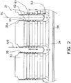
- the heat transfer fin 31 includes a windward main portion 33 formed with a notch 35 that receives the flat tube 21, and a leeward communication portion 34 located on a side opposite to an open end 35a of the notch 35.
- a plurality of the notches 35 that receive the plurality of flat tubes 21 are formed along the width direction of the flat tube 21.
- the notches 35 extend in the air flow direction (direction of the arrow Ar9).
- the flat tube 21 is inserted in the direction of the arrow Ar9 in FIG. 2 .
- a guide rib 36 that facilitates condensed water discharge is formed in the communication portion 34.
- This guide rib 36 is a portion that extends from a pressed groove.
- a protruded structure extends in the up-down direction along the guide rib 36 when the guide rib 36 is viewed from a one main surface f1 of the heat transfer fin 31, while a recessed structure extends in the up-down direction along the guide rib 36 when the guide rib 36 is viewed from an other main surface on a side opposite to the one main surface fl.
- FIG. 3 illustrates a cross section taken along the line I-I in FIG. 2 .
- FIG. 4 illustrates a state of the heat transfer fin 31 illustrated in FIG. 2 when viewed from a direction perpendicular to the air flow direction (direction of the arrow Ar9).
- collar portions 60 are formed on the side of the one main surface fl of the first heat transfer fin 31.
- a plurality of raised-lance elements 37 that protrude in a bridge shape are formed on the side of an other main surface f2 of the heat transfer fin 31.
- the collar portion 60 has a U-shape so as to surround the notch 35 when the heat transfer fin 31 is viewed in plan (when viewed along the direction in which the flat tube 21 extends).
- a flat tube 21 that is inserted into the notch 35 is fixed to the collar portion 60 by brazing.
- FIG. 5 illustrates an area around the collar portion 60 illustrated in FIG. 2 in an enlarged manner.
- Each of the plurality of heat transfer fins 31 includes, in the collar portion 60, three types of standing portions 61, 62, 63 provided on a peripheral portion of each notch 35 for forming a gap with an adjacent heat transfer fin 31.
- the collar portion 60 includes six wave-shaped standing portions 61, five wave-shaped standing portions 62 and one standing portion 63. Therefore, the number of standing portions 61, 62, 63 included in the collar portion 60 is 12.
- At least three standing portions 61, 62, 63 are provided so that the standing portions 61, 62, 63 do not face each other across a reference line RL that extends in the width direction through the perpendicular center portion of the flat tube 21.
- the 12 standing portions 61, 62, 63 are arranged so as not to face each other.
- a plurality standing portions 61 and a plurality of standing portions 62 are provided on each of two long sides 68, 69 of the notch 35.
- the two long sides 68, 69 face each other across the reference line RL.
- six standing portions 61 are disposed on the long side 68 and five standing portions 62 are disposed on the long side 69.
- the six standing portions 61 and the five standing portions 62 are alternately arranged along the reference line RL.
- the long sides 68, 69 are linear portions along flat surfaces formed in the flat tube 21.
- a length L1 of the portion in which the standing portions 61 are formed and a length L2 of the portion in which the standing portions 62 are formed are both larger than half a width W1 of the flat tube 21.
- at least one standing portion 63 is arranged at a deepest portion 67 of the notch 35 in each of the plurality of heat transfer fins 31.
- only one standing portion 63 is provided, but a plurality of standing portions 63 may be provided through, for example, forming the standing portion 63 as a forked shape.
- the standing portion 63 has a function of restricting the flat tube 21 when the flat tube 21 is inserted. In other words, the flat tube 21 is pushed into the notch 35 until the flat tube 21 abuts against the standing portion 63.
- the standing portions 61, 62 have wave-like shapes so that the standing portions 61, 62 on the two long sides 68, 69 of the notch 35 can be fitted into each other when they are pushed down into the notch 35.
- a cutting line 70 of the wave-like shape may be formed in a metal plate as the material of the heat transfer fin 31 through, for example, press molding.
- the heat transfer fin 31 is configured such that, when viewed from the wind direction, a height h1 at which the interval between the standing portion 61 disposed on the one long side 68 of the notch 35 and the standing portion 62 disposed on the other long side 69 is a minimum value D1 is less than half a height h2 of the standing portions 61, 62.
- a height h3 that is a height from a crest portion 61a, 61b of the standing portion 61, 62 to the position at which the interval becomes the minimum value D1 is smaller than the height h1 at which the interval is the minimum value D1 (h1 ⁇ h3). This means that the portion at which the interval is the minimum value D1 is formed closer to the one main surface fl of the heat transfer fin 31.
- FIG. 8 illustrates three heat transfer fins 31 of a plurality of stacked heat transfer fins 31.
- the gap between adjacent heat transfer fins 31 is formed by the collar portion 60.
- adjacent heat transfer fins 31 have a predetermined fin pitch Pt. This fin pitch Pt is equal to an interval between adjacent one main surfaces fl.
- Each of the plurality of stacked heat transfer fins 31 illustrated in FIG. 8 includes a base 65 that is a flat portion.
- the standing portions 61, 62 of the collar portions 60 in one heat transfer fin 31 abut against the base 65 of an adjacent heat transfer fin 31.
- Each of the plurality of heat transfer fins 31 has the raised-lance element 37 as a protruding portion that is formed between adjacent notches 35 and that protrudes in a direction opposite to the standing portions 61, 62.
- the protruding portion is not limited to the raised-lance element 37 and may be any portion that has been, for example, punched out.
- the base 65 of each heat transfer fin 31 is formed between the raised-lance element 37 and the notch 35.
- the standing portions 61, 62 automatically slide down from the raised-lance elements 37 as the protruding portions and gather at the bases 65 when a large number of three or more heat transfer fins 31 are stacked upon assembling the heat exchanger 91. Because the standing portions 61, 62 can easily move toward the bases 65 without stopping at the raised-lance elements 37 when the plurality of heat transfer fins 31 is stacked, stacking work takes less time and manufacturing labor and time can be reduced, which results in lower manufacturing costs. As illustrated in FIG.
- a distance X1 from an edge 66 of the notch 35 to an end portion of the standing portion 61, 62 is set smaller than a distance X3 from the edge 66 of the notch 35 to the raised-lance element 37 so that the base 65 and the standing portion 61, 62 can easily abut against each other.
- each heat transfer fin 31 has a reflare portion 41 in which the standing portion 61 is bent into an curved shape on a side opposite to the notch 35 and a reflare portion 42 in which the standing portion 62 is bent into an curved shape on a side opposite to the notch 35.
- the crest portions 61a, 62a of the reflare portions 41, 42 where the standing height of the standing portions 61, 62 is at a maximum are located outward than the edge 66 of the notch 35 by a predetermined distance X2.
- the distance X2 is set such that the flat base 65 is larger than a distance X4 from the edge 66 of the notch 35.
- the distance X2 is preferably set at least 0.2 mm larger than the distance X4 (X2 - X4 ⁇ 0.2 mm).
- the standing portion 63 is arranged at the deepest portion of the notch 35, but the standing portion 63 may be omitted.
- the standing portions 61, 62 formed into the wave-shape depict a wavy line that looks like a sine wave, but the wave shape formed by the standing portions 61, 62 does not need to be a wavy line and also includes, for example, a shape in which a triangle shape or a square shape repeats.
- the heat transfer fin 31 communicates on the leeward side (see FIG. 1 ), but the heat transfer fin may communicate on the windward side.
- the heat exchanger according to the first embodiment of the present invention can be applied to an indoor unit of an air conditioner, an outdoor unit of an air conditioner, or a heat exchanger for a vehicle.
- the standing portions 61, 62, 63 in the collar portions 60 of each of the plurality of heat transfer fins 31 are arranged so as not to face each other across the reference line RL that extends in the width direction through the perpendicular center portion of the flat tube 21. Because of this, sufficient standing height of the standing portions 61, 62, 63 can be ensured and the fin pitch Pt (see FIG. 8 ) can be maintained with the standing portions 61, 62, 63. In addition, through providing three or more of the standing portions 61, 62, 63, the positional relationship between adjacent heat transfer fins 31 can be stabilized, and strength of the brazed heat transfer fins 31 can be stably maintained.
- the three or more standing portions may be combined such that there are, for example, two standing portions 61 and one standing portion 62, or one standing portion 61 and two standing portions 62.
- a plurality of standing portions 61, 62 are provided on each long side 68, 69 of the notch 35, and hence stability is improved when the plurality of heat transfer fins 31 are stacked. Improving stability means that the positional relationship between adjacent heat transfer fins 31 is accurately determined. Therefore, high dimensional accuracy can be afforded to the positional relationship between the plurality of heat transfer fins 31.
- the standing portions 61, 62 on the two long sides 68, 69 are alternately arranged along the reference line RL, the standing portions 61, 62 can be made taller. Because the standing portions 61, 62 are formed by raising a piece of metal at a portion of the notch 35, the height thereof is naturally restricted by the size of the piece of metal at the portion of the notch 35. However, because the standing portions 61, 62 are alternately arranged along the reference line RL, the distance from the crest portions 61a, 61b of the standing portions 61, 62 to the long sides 68, 69 when taken along the section illustrated in FIG.
- the length from the crest portions 61a, 61b of the standing portions 61, 62 to the long sides 68, 69 can be easily secured even if the flat tube 21 is thin in the direction perpendicular to the width direction.
- the length from the crest portions 61a, 61b of the standing portions 61, 62 to the long sides 68, 69 can be secured even if the flat tube 21 is thin, and even a thin flat tube in the thickness direction is within the applicable range of the flat tube 21.
- the standing portions 61, 62 on the two long sides 68, 69 form wave-shapes that can be fitted into each other when pushed down into the notch 35, the crest portions 61a, 61b of the wave-shaped standing portions 61, 62 can be made taller, and the member notched with the notch 35 can be utilized to the fullest extent. Even when a thin flat tube 21 is used, high dimensional accuracy and mounting strength can easily be obtained in terms of the positional relationship between the plurality of heat transfer fins 31.
- the range in which the standing portions 61, 62, 63 are arranged in the direction of the reference line RL in the notch 35 can be made longer.
- the length of a standing portion arrangement area when the standing portion 63 is not provided is the length L1 or L2, but the length of the standing portion arrangement area when the standing portion 63 is provided can be extended up until the length L3.
- the standing portion 63 arranged at the deepest portion 67 also has a function of restricting the flat tube when the flat tube is inserted. As a result, dimensional accuracy between the stacked heat transfer fins 31, and dimensional accuracy and mounting strength between the heat transfer fins 31 and the flat tubes 21 can be improved.
- the heat transfer fins 31 and the flat tubes 21 make sufficient contact near the main surfaces fl at which the standing portions 61, 62 of the heat transfer fins 31 stand up.
- the flat tube 21 can be prevented from catching on the notch 35 in the heat transfer fin 31 when the flat tube 21 is inserted into the notch 35, and the shape of the heat exchanger 91 can be prevented from distorting due to catching.
- good heat conductivity between the heat transfer fins 31 and the flat tubes 21 can be achieved by shortening the distance between the main surfaces fl of the heat transfer fins 31 and the flat tubes 21. As a result, dimensional accuracy between the stacked heat transfer fins 31, and dimensional accuracy and mounting strength between the heat transfer fins 31 and the flat tubes 21 can be improved.
- the standing portion 61, 62 on one of the adjacent heat transfer fins 31 is formed so as to abut against the base 65 (example of flat portion) of the other adjacent heat transfer fin 31, the standing portion 61, 62 can easily move to the base 65 without stopping at the raised-lance element 37 (example of protruding portion) when the plurality of heat transfer fins 31 is stacked, and hence stacking time can be shortened and manufacturing costs can be reduced. Due to reducing manufacturing costs, the heat exchanger 91 can be provided at low cost.
- a heat exchanger according to a second embodiment of the present invention is described with reference to FIGS. 10 to 17 .
- the heat exchanger according to the second embodiment has the same configuration as the heat exchanger 91 according to the first embodiment illustrated in FIG. 1 apart from details of a heat transfer fin 31A illustrated in FIG. 10A .
- the heat exchanger 91 according to the second embodiment also includes the first heat exchange portion 96 and the second heat exchange portion 97. Further, in the second embodiment, the first heat exchange portion 96 and the second heat exchange portion 97 each include a plurality of flat tubes 21A (see FIG. 10A ) arranged in a row and a plurality of heat transfer fins 31A that intersect with the plurality of flat tubes 21A.
- the positional relationship between the plurality of flat tubes 21A and the plurality of heat transfer fins 31A and the configuration of the flat tube 21A according to the second embodiment are substantially the same as the positional relationship between the plurality of flat tubes 21 and the plurality of heat transfer fins 31 and the configuration of the flat tube 21 according to the first embodiment, and hence a description thereof is omitted.
- FIGS. 10A, 10B and 10C illustrate a part of the heat transfer fin 31A in an enlarged manner.
- FIG. 10A illustrates the heat transfer fin 31A in a state in which the flat tube 21A is inserted into the notch 35 and
- FIG. 10C illustrates the heat transfer fin 31A in a state in which the flat tube 21A is not inserted into the notch 35.
- FIG. 10B is an illustration for explaining a brazing portion of the flat tube 21A and the heat transfer fin 31.
- the notch 35 that receives the flat tube 21A is formed in the windward main portion 33 and the leeward communication portion 34 is located on a side opposite to the open end 35a of the notch 35.
- the heat transfer fin 31A also includes the guide rib 36 and the collar portions 60 formed on the one main surface fl.
- a portion at which the flat tube 21A makes contact with the collar portion 60 is the portion indicated by hatching in FIG. 10B .
- the portion at which the flat tube 21A makes contact with the collar portion 60 is brazed.
- the shape of the notch 35 in plan view only needs to substantially match the external shape of the flat tube 21A in order to make the flat tube 21A contact with the collar portion 60 in a U-shape when viewed in plan.
- Each of the plurality of heat transfer fins 31A includes, in the collar portion 60, the three types of standing portions 61, 62, 63 provided on a peripheral portion of each notch 35 for forming gaps between adjacent heat transfer fins 31A.
- the collar portion 60 includes seven wave-shaped standing portions 61, eight wave-shaped standing portions 62 and one wave-shaped standing portion 63.
- the standing portions 61 on either end of the long side 68 do not form a sufficient wave-shape and hence are not counted as one standing portion 61. Therefore, the number of standing portions 61, 62, 63 included in the collar portion 60 is 16 in total.
- At least three standing portions 61, 62, 63 are arranged so as not to face each other across the reference line RL that extends in the width direction through the perpendicular center portion of the flat tube 21.
- 12 standing portions 61, 62, 63 are arranged so as not to face each other.
- a plurality of the wave-shaped standing portions 61 are arranged on the long side 68 of the notch 35 and a plurality of the wave-shaped standing portions 62 are arranged on the long side 69 of the notch 35.
- the two long sides 68, 69 of the notch 35 face each other across the reference line RL.
- the plurality of standing portions 61 and the plurality of the standing portions 62 are alternately arranged along the reference line RL.
- the long sides 68, 69 are linear portions along flat surfaces formed in the flat tube 21A.
- the standing portions 61, 62 on the two long sides 68, 69 in the notch 35 are formed into the wave shapes such that the standing portions 61, 62 can be fitted into each other when pushed down into the notch 35. This feature is also the same as the first embodiment.
- a distance X5 between a wave crest P1 of a standing portion 61 on one end of the long side 68 and a wave crest P2 of a standing portion 61 on the other end of the long side 68 is set to be at least one third of a width W2 of the flat tube 21A.
- a distance X6 between a wave crest P3 of a standing portion 62 on one end of the long side 69 and a wave crest P4 of a standing portion 62 on the other end of the long side 69 is set to be at least one third of the width W2 of the flat tube 21A.
- FIGS. 11 and 12 show a cross section taken along the line II-II and a cross section taken along the line III-III of the collar portion 60 illustrated in FIG. 10A .
- the standing portions 61, 62 makes contact with a flat surface 22 of the flat tube 21A at a contact portion P5 illustrated in FIG. 11 .
- the collar portion 60 makes contact with the flat surface 22 of the flat tube 21A at portions other than the wave-shaped standing portions 61, 62 (contact portion P6).
- FIG. 13 illustrates three of the plurality of stacked heat transfer fins 31A.
- the gap between adjacent heat transfer fins 31A is formed by the collar portions 60. This gap is the fin pitch Pt between the plurality of heat transfer fins 31A.
- the plurality of heat transfer fins 31A also include the bases 65 and the raised-lance elements 37. As illustrated in FIG. 14 , the distance X1 from the edge 66 of the notch 35 to the end portions of the standing portions 61, 62 is set smaller than the distance X3 from the edge 66 of the notch 35 to the raised-lance element 37 so that the bases 65 and the standing portions 61, 62 easily abut against each other.
- each heat transfer fin 31A has a reflare portion 43 in which the standing portion 61 is bent into an curved shape on a side opposite to the notch 35 and a reflare portion 44 in which the standing portion 62 is bent into an curved shape on a side opposite to the notch 35.
- the reflare portions 43, 44 according to the second embodiment illustrated in FIG. 14 differ from the reflare portions 41, 42 according to the first embodiment illustrated in FIG. 9 in that the reflare portions 43, 44 extend completely straight in the longitudinal direction of the main portion 33. Compared to a case where the reflare portions 41, 42 extend diagonally such that tips thereof approach the main portion 33, air resistance can be reduced in a case where the reflare portions 43, 44 extend completely straight.
- the crest portions 61a, 62a of the reflare portions 43, 44 where the standing height of the standing portions 61, 62 is at a maximum are located outward than the edge 66 of the notch 35 by the predetermined distance X2.
- the crest portions 61a, 62a of the reflare portions 43, 44 are flat and the predetermined distance X2 is defined as the distance closest to the edge 66 of the flat crest portions 61a, 62a.
- the distance X2 is set such that the flat base 65 is larger than the distance X4 from the edge 66 of the notch 35.
- the distance X2 is preferably set at least 0.2 mm larger than the distance X4 (X2 - X4 ⁇ 0.2 mm).
- the standing portion 63 does not need to be arranged at the deepest portion of the notch 35.
- the standing portions 61, 62 formed into the wave-shape depict a wavy line that looks like a sine wave, but the wave shape formed by the standing portions 61, 62 does not need to be a wavy line and also includes, for example, a shape in which a triangle shape or a square shape repeats, as in the first embodiment.
- the plurality of wave-shaped standing portions 61, 62 are continuous on each long side 68, 69.
- the plurality of wave-shaped standing portions 61, 62 do not need to be continuous.
- the length of the wave formed by the standing portions 61, 62 repeating on each long side 68, 69 is constant.
- the length of the wave shape formed by the plurality of standing portions 61, 62 repeating may not be constant.
- the standing portions 61, 62 repeatedly alternate one by one on each long side 68, 69 to form the wave shape, but the standing portions 61, 62 are not limited to repeating in this way.
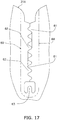
- FIG. 17 there may be adopted a configuration in which three standing portions 61 are arranged between two standing portions 62.
- the heat transfer fin 31A communicates on the leeward side (see FIG. 1 ), but the heat transfer fin may communicate on the windward side.
- the heat exchanger according to the second embodiment of the present invention can be applied to an indoor unit of an air conditioner, an outdoor unit of an air conditioner, or a heat exchanger for a vehicle.
- the heat exchanger 91 according to the second embodiment also achieves the actions and effects described in sections (4-1) to (4-8).
- the plurality of standing portions 61, 62 on each long side 68, 69 forms the wave shape. Because the standing portions 61, 62 form the wave shape, the crest portions of the wave-shaped standing portions 61 or standing portions 62 on one of the long side 68 or the long side 69 are made to correspond to trough portions of the wave-shaped standing portions 61 or standing portions 62 on the other of the long side 69 or the long side 68. Therefore, the plurality of standing portions 61, 62 on each long side 68, 69 are more easily formed high. For example, the crest portion P11 of the standing portion 61 illustrated in FIG.
- the crest portion P12 of the standing portion 62 corresponds to the trough portion B2 of the standing portion 61. Because the plurality of standing portions 61, 62 can be more easily made taller, it is easier to adopt a thin flat tube 21, 21A and the heat exchanger can be more widely applied.
- a case where the wave-shaped standing portions 61, 62 are cut and separated at the cutting line 70 is described as a case of forming the wave-shaped standing portions 61, 62, but the method for separating the standing portions 61, 62 is not limited to using the cutting line 70 and may involve, for example, forming a thin groove between the standing portions 61, 62 to separate the standing portions 61, 62. Even in this case, an effect of more easily forming the plurality of standing portions 61, 62 taller on each long side 68, 69 is achieved.
- a portion at which the distance is smallest when, for example, the portion at the crest portion of the standing portion is parallel to the reference line RL shall be measured.
- the distance X5, X6 between the wave crest PI, P3 of the wave-shaped standing portion 61, 62 on one end of the standing portions 61, 62 on the two long sides 68, 69 and a wave crest P2, P4 of the standing portion 61, 62 on the other end of the standing portions 61, 62 is at least one third of the width of the flat tube 21A. In other words, it is easier to extend the distance along which the long sides 68, 69 abut against the adjacent heat transfer fins 31A to at least one third of the width of the flat tube 21A.
- the heat transfer fins 31A are more easily stabilized when the plurality of heat transfer fins 31A are stacked and it is easier to obtain a heat exchanger 91 having even intervals between the heat transfer fins 31A.
- the distance X5, X6 between the wave crest of a standing portion 61, 62 on one end of the standing portions 61, 62 on the two long sides 68, 69 and a wave crest of a standing portion 61, 62 on the other end of the standing portions 61, 62 is at least one third of the width of the flat tube 21A and produces the same effect as the second embodiment.
- Patent Literature 1 Japanese Patent Unexamined Publication 2012-163318
Landscapes
- Engineering & Computer Science (AREA)
- Physics & Mathematics (AREA)
- Thermal Sciences (AREA)
- Mechanical Engineering (AREA)
- General Engineering & Computer Science (AREA)
- Geometry (AREA)
- Heat-Exchange Devices With Radiators And Conduit Assemblies (AREA)
Abstract
Description
- The present invention relates to a heat exchanger, more particularly, to a heat exchanger used for exchanging heat between air and refrigerant.
- There is known a heat exchanger such as the one described in Patent Literature 1 (Japanese Patent Unexamined Publication
2012-163318 - However, as described in Patent Literature 1, air flow resistance increases when the raised-lance element is disposed perpendicular to an air flow direction. Arranging the raised-lance element parallel to the air flow direction in order to avoid an increase in air flow resistance could be conceived to solve this problem, but drainability of condensed water decreases if the raised-lance element is arranged parallel to the air flow direction.
- It is an object of the present invention to provide a high-quality heat exchanger in which flat tubes are inserted into notches in heat transfer fins, that can reduce an increase in air flow resistance and a decrease in drainability of condensed water while ensuring fin pitch.
- A heat exchanger according to a first aspect of the present invention is a heat exchanger including a plurality of flat tubes that each have a cross-sectional shape perpendicular to a direction of flow of refrigerant with a width direction that extends in an air flow direction; and a plurality of heat transfer fins each having a plurality of notches configured to receive the plurality of flat tubes, the plurality of notches being along the width direction of the plurality of flat tubes, in which the plurality of heat transfer fins includes at least three standing portions provided on a peripheral portion of each of the plurality of notches for forming gaps between adjacent heat transfer fins, and the at least three standing portions are arranged so as not to face each other across a reference line that extends in the width direction through a perpendicular center portion of the flat tube.
- In the heat exchanger according to the first aspect of the present invention, because the standing portions are arranged so as not to face each other across the reference line that extends in the width direction through the perpendicular center portion of the flat tube, sufficient standing height of the standing portion can be ensured and fin pitch can be maintained by the standing portions. In addition, by providing at least three standing portions, the positional relationship between adjacent heat transfer fins can be stabilized, and strength of the brazed heat transfer fins can be stably secured.
- A heat exchanger according to a second aspect of the present invention is the heat exchanger according to the first aspect, in which each of the plurality of heat transfer fins includes, in the notch, a plurality of the standing portions on each of two long sides that face each other across the reference line.
- In the heat exchanger according to the second aspect of the present invention, a plurality of standing portions is provided on each long side of the notch, and hence stability can be improved when the plurality of heat transfer fins are stacked.
- A heat exchanger according to a third aspect of the present invention is the heat exchanger according to the second aspect of the present invention, in which, in each of the plurality of heat transfer fins, the standing portions on the two long sides of the notches are alternately arranged along the reference line.
- In the heat exchanger according to the third aspect of the present invention, because the standing portions on the two long sides are alternately arranged along the reference line, the standing portions can be made taller and a range compatible with a thickness direction of the flat tube perpendicular to the width direction of the flat tube can be expanded to include a thin flat tube.
- A heat exchanger according to a fourth aspect of the present invention is the heat exchanger according to the third aspect, in which, in each of the plurality of heat transfer fins, the standing portions on the two long sides of the notch each form a wave-shape such that the standing portions can be fitted into one another when pushed down into the notch.
- In the heat exchanger according to the fourth aspect of the present invention, because the standing portions on the two long sides each form a wave-shape such that the standing portions can be fitted into one another when pushed down into the notch, the height of the wave-shaped standing portions until the crest portions can be increased, and the member notched with the notch can be utilized to the fullest extent.
- A heat exchanger according to a fifth aspect of the present invention is the heat exchanger according to the second aspect, in which, in each of the plurality of heat transfer fins, each of the plurality of standing portions on each of the long sides forms a wave-shape.
- In the heat exchanger according to the fifth aspect of the present invention, because the standing portions form the wave-shape, the crest portions of the wave-shaped standing portions on one long side can be made to correspond to the trough portions of the wave-shaped standing portions on the other long side, and hence a plurality of standing portions can easily be made taller.
- A heat exchanger according to a sixth aspect of the present invention is the heat exchanger according to the fifth aspect, in which, in each of the plurality of heat transfer fins, a distance from a wave crest of one of the standing portions in the wave-shaped standing portions on an end of at least one of the two long sides to a wave crest of one of the standing portions in the wave-shaped standing portions on an other end of the at least one of the two long sides is at least one third of a width of the flat tube.
- In the heat exchanger according to the sixth aspect of the present invention, because the distance from the wave crest of one of the standing portions in the wave-shaped standing portions on an end of at least one of the two long sides to a wave crest of one of the standing portions in the wave-shaped standing portions on an other end of the at least one of the two long sides is at least one third of a width of the flat tube, the distance that abuts against adjacent heat transfer fins on the long side can be extended to at least one third of the width of the flat tube.
- A heat exchanger according to a seventh aspect of the present invention is the heat exchanger according to any one of the first to sixth aspects, in which, in each of the plurality of heat transfer fins, at least one of the standing portions is arranged at a deepest portion of the notch.
- In the heat exchanger according to the seventh aspect of the present invention, because at least one standing portion is arranged at the deepest portion of the notch, the range in which the standing portions are arranged in a direction along the reference line of the notch can be made longer. In addition, the standing portion arranged at the deepest portion has a function of restricting the flat tube when the flat tube is inserted.
- A heat exchanger according to an eighth aspect of the present invention is the heat exchanger according to any one of the second to seventh aspects, wherein, in each of the plurality of heat transfer fins, when viewed from an air flow direction, a height at which intervals between the standing portions disposed on one of the long sides of the notch and the standing portions disposed on the other of the long sides of the notch is at a minimum is less than half of a height of the standing portion.
- In the heat exchanger according to the eighth aspect of the present invention, when viewed from the air flow direction, because the height at which the intervals between the standing portions is at a minimum is smaller than half the height of the standing portion, the heat transfer fin and the flat tube sufficiently make contact near a main surface on which the standing portions of the heat transfer fin stand up. By shortening the distance between this point of contact and the main surface of the heat transfer fin, good heat conductivity is achieved between the heat transfer fin and the flat tube. In addition, the flat tube can be unlikely to catch on the notch in the heat transfer fin when the flat tube is inserted into the notch, and the shape distortion of the heat exchanger due to the catching can be reduced.
- A heat exchanger according to a ninth aspect of the present invention is the heat exchanger according to any one of the first to eighth aspects, in which, each of the plurality of heat transfer fins includes a protruding portion that is provided between adjacent notches and protrudes in a direction opposite to the standing portion, and a flat portion provided between the protruding portion and the notch, and in which the standing portion of one of adjacent heat transfer fins is provided so as to abut against the flat portion of another of the adjacent heat transfer fins.
- In the heat exchanger according to the ninth aspect of the present invention, one standing portion in adjacent heat transfer fins is provided so as to abut against another flat portion, and hence the standing portion can easily move to the flat portion without stopping at the protruding portion when the plurality of heat transfer fins are stacked, and hence stacking time can be easily shortened and manufacturing costs can be reduced.
- A heat exchanger according to a tenth aspect of the present invention is the heat exchanger according to any one of the first to ninth aspects, in which each of the plurality of heat transfer fins has a reflare portion in which each of the standing portions is bent into an curved shape on a side opposite to the notch, and in which a position of the reflare portion at which the height of the standing portion is at a maximum is located outward of an edge of the notch by a predetermined distance.
- In the heat exchanger according to the tenth aspect of the present invention, because the position of the reflare portion at which the height of the standing portion is at a maximum is located outward of the edge of the notch by a predetermined distance, an error in the fin pitch caused by deformation around the notch can be reduced.
- With the heat exchanger according to the first aspect of the present invention, there is no need to provide extra raised-lance elements for a gap between adjacent fins in, for example, an air flow passage, and hence an increase in air flow resistance and a decrease in drainability of condensed water can be reduced and there can be provided a high-quality heat exchanger having stable fin pitch and mounting strength of the heat transfer fins.
- With the heat exchanger according to the second aspect of the present invention, high dimensional accuracy can be obtained in terms of the positional relationship between the plurality of heat transfer fins.
- With the heat exchanger according to the third or fifth aspect of the present invention, it is easier to employ a thin flat tube and the thin flat tube has a larger applicable range.
- With the heat exchanger according to the fourth aspect of the present invention, it is easier to obtain high dimensional accuracy and mounting strength in terms of the positional relationship between the plurality of heat transfer fins even when a thin flat tube is employed.
- With the heat exchanger according to the sixth aspect of the present invention, the heat transfer fins can be more easily stabilized when the plurality of heat transfer fins are stacked and it is easier to provide a heat exchanger that has even intervals between heat transfer fins.
- With the heat exchanger according to the seventh aspect of the present invention, dimensional accuracy between the stacked heat transfer fins and dimensional accuracy and mounting strength between the heat transfer fins and the flat tubes can be increased.
- With the heat exchanger according to the eighth aspect of the present invention, good heat conductivity between the heat transfer fin and the flat tube can be stably secured and high product quality can be maintained.
- With the heat exchanger according to the ninth aspect of the present invention, costs can be reduced and the heat exchanger can be provided at low cost.
- With the heat exchanger according to the tenth aspect of the present invention, dimensional accuracy of the stacked heat transfer fins can be improved.
-
-
FIG. 1 is a cross-sectional view for illustrating the structure of a heat exchanger and its vicinity according to a first embodiment. -
FIG. 2 is a partially expanded plan view of a part of a heat transfer fin. -
FIG. 3 is a cross-sectional view for illustrating the heat transfer fin taken along the line I-I inFIG. 2 . -
FIG. 4 is a side view for illustrating the heat transfer fin. -
FIG. 5 is a partially expanded plan view for illustrating the heat transfer fin in which an area around a notch of the heat transfer fin is expanded. -
FIG. 6 is a partially expanded plan view of the material of the heat transfer fin for explaining a method for forming a standing portion. -
FIG. 7 is a partially expanded cross-sectional view of an area around the standing portion. -
FIG. 8 is a partially expanded cross-sectional view for illustrating a state in which a plurality of heat transfer fins are stacked. -
FIG. 9 is a partially expanded cross-sectional view for explaining the shape of the standing portion. -
FIG. 10A is a partially expanded view of part of the heat transfer fin and a flat tube;FIG. 10B is an expanded plan view of the heat transfer fin for explaining a brazing portion of the flat tube; andFIG. 10C is a partially expanded plan view of part of the heat transfer fin. -
FIG. 11 is a cross-sectional view of the heat transfer fin and the flat tube taken along the line II-II inFIG. 10 . -
FIG. 12 is a cross-sectional view of the heat transfer fin and the flat tube taken along the line III-III inFIG. 10 . -
FIG. 13 is a partially expanded cross-sectional view for illustrating a state in which a plurality of heat transfer fins are stacked. -
FIG. 14 is a partially expanded cross-sectional view for explaining the shape of the standing portion. -
FIG. 15 is a partially expanded plan view of the material of the heat transfer fin for explaining another exemplary method for forming the standing portion. -
FIG. 16 is a partially expanded plan view of the material of the heat transfer fin for explaining yet another exemplary method for forming the standing portion. -
FIG. 17 is a partially expanded plan view of the material of the heat transfer fin for explaining further another exemplary method for forming the standing portion. - A heat exchanger according to a first embodiment of the present invention is described with reference to
FIGS. 1 to 9 . - As illustrated in
FIG. 1 , aheat exchanger 91 includes a firstheat exchange portion 96 and a secondheat exchange portion 97. The firstheat exchange portion 96 is disposed on a windward side and the secondheat exchange portion 97 is disposed on a leeward side. Both the firstheat exchange portion 96 and the secondheat exchange portion 97 include a plurality offlat tubes 21 arranged in rows and a plurality ofheat transfer fins 31 that intersect with the plurality offlat tubes 21. Theflat tubes 21 and theheat transfer fins 31 are substantially orthogonal to each other. Only oneheat transfer fin 31 of each of the firstheat exchange portion 96 and the secondheat exchange portion 97 is illustrated inFIG. 1 . Otherheat transfer fins 31 that are adjacent to theheat transfer fins 31 illustrated inFIG. 1 are arranged parallel to theheat transfer fins 31 inFIG. 1 . - As illustrated in
FIG. 1 , a plurality offlow passages 21a are formed as one windward-to-leeward row inside oneflat tube 21, and the refrigerant flows through each of theseflow passages 21a. In other words, the width direction of the cross-sectional shape of theflat tube 21 perpendicular to the direction of flow of refrigerant in eachflow passage 21a extends in an air flow direction (direction of the arrow Ar9). - In
FIG. 2 , a part of theheat transfer fin 31 is illustrated in a further expanded manner. Theheat transfer fin 31 includes a windwardmain portion 33 formed with anotch 35 that receives theflat tube 21, and aleeward communication portion 34 located on a side opposite to anopen end 35a of thenotch 35. In theheat transfer fin 31, a plurality of thenotches 35 that receive the plurality offlat tubes 21 are formed along the width direction of theflat tube 21. In other words, thenotches 35 extend in the air flow direction (direction of the arrow Ar9). Theflat tube 21 is inserted in the direction of the arrow Ar9 inFIG. 2 . Aguide rib 36 that facilitates condensed water discharge is formed in thecommunication portion 34. Thisguide rib 36 is a portion that extends from a pressed groove. A protruded structure extends in the up-down direction along theguide rib 36 when theguide rib 36 is viewed from a one main surface f1 of theheat transfer fin 31, while a recessed structure extends in the up-down direction along theguide rib 36 when theguide rib 36 is viewed from an other main surface on a side opposite to the one main surface fl. -
FIG. 3 illustrates a cross section taken along the line I-I inFIG. 2 . In addition,FIG. 4 illustrates a state of theheat transfer fin 31 illustrated inFIG. 2 when viewed from a direction perpendicular to the air flow direction (direction of the arrow Ar9). As illustrated inFIGS. 3 and4 ,collar portions 60 are formed on the side of the one main surface fl of the firstheat transfer fin 31. A plurality of raised-lance elements 37 that protrude in a bridge shape are formed on the side of an other main surface f2 of theheat transfer fin 31. Thecollar portion 60 has a U-shape so as to surround thenotch 35 when theheat transfer fin 31 is viewed in plan (when viewed along the direction in which theflat tube 21 extends). Aflat tube 21 that is inserted into thenotch 35 is fixed to thecollar portion 60 by brazing. -
FIG. 5 illustrates an area around thecollar portion 60 illustrated inFIG. 2 in an enlarged manner. Each of the plurality ofheat transfer fins 31 includes, in thecollar portion 60, three types of standingportions notch 35 for forming a gap with an adjacentheat transfer fin 31. In this embodiment, thecollar portion 60 includes six wave-shapedstanding portions 61, five wave-shapedstanding portions 62 and one standingportion 63. Therefore, the number of standingportions collar portion 60 is 12. At least three standingportions portions flat tube 21. In this embodiment, the 12 standingportions - In addition, in the plurality of
heat transfer fins 31, aplurality standing portions 61 and a plurality of standingportions 62 are provided on each of twolong sides notch 35. The twolong sides portions 61 are disposed on thelong side 68 and five standingportions 62 are disposed on thelong side 69. The six standingportions 61 and the five standingportions 62 are alternately arranged along the reference line RL. Thelong sides flat tube 21. A length L1 of the portion in which the standingportions 61 are formed and a length L2 of the portion in which the standingportions 62 are formed are both larger than half a width W1 of theflat tube 21. In addition, at least one standingportion 63 is arranged at adeepest portion 67 of thenotch 35 in each of the plurality ofheat transfer fins 31. In this embodiment, only one standingportion 63 is provided, but a plurality of standingportions 63 may be provided through, for example, forming the standingportion 63 as a forked shape. The standingportion 63 has a function of restricting theflat tube 21 when theflat tube 21 is inserted. In other words, theflat tube 21 is pushed into thenotch 35 until theflat tube 21 abuts against the standingportion 63. - As illustrated in
FIG. 6 , the standingportions portions long sides notch 35 can be fitted into each other when they are pushed down into thenotch 35. In order to form the standingportions line 70 of the wave-like shape may be formed in a metal plate as the material of theheat transfer fin 31 through, for example, press molding. - As illustrated in
FIG. 7 , theheat transfer fin 31 is configured such that, when viewed from the wind direction, a height h1 at which the interval between the standingportion 61 disposed on the onelong side 68 of thenotch 35 and the standingportion 62 disposed on the otherlong side 69 is a minimum value D1 is less than half a height h2 of the standingportions crest portion 61a, 61b of the standingportion heat transfer fin 31. -
FIG. 8 illustrates threeheat transfer fins 31 of a plurality of stackedheat transfer fins 31. The gap between adjacentheat transfer fins 31 is formed by thecollar portion 60. In other words, adjacentheat transfer fins 31 have a predetermined fin pitch Pt. This fin pitch Pt is equal to an interval between adjacent one main surfaces fl. - Each of the plurality of stacked
heat transfer fins 31 illustrated inFIG. 8 includes a base 65 that is a flat portion. The standingportions collar portions 60 in oneheat transfer fin 31 abut against thebase 65 of an adjacentheat transfer fin 31. Each of the plurality ofheat transfer fins 31 has the raised-lance element 37 as a protruding portion that is formed betweenadjacent notches 35 and that protrudes in a direction opposite to the standingportions lance element 37 and may be any portion that has been, for example, punched out. Thebase 65 of eachheat transfer fin 31 is formed between the raised-lance element 37 and thenotch 35. Because theheat transfer fins 31 are provided with thebases 65, the standingportions lance elements 37 as the protruding portions and gather at thebases 65 when a large number of three or moreheat transfer fins 31 are stacked upon assembling theheat exchanger 91. Because the standingportions bases 65 without stopping at the raised-lance elements 37 when the plurality ofheat transfer fins 31 is stacked, stacking work takes less time and manufacturing labor and time can be reduced, which results in lower manufacturing costs. As illustrated inFIG. 9 , a distance X1 from anedge 66 of thenotch 35 to an end portion of the standingportion edge 66 of thenotch 35 to the raised-lance element 37 so that thebase 65 and the standingportion - As illustrated in
FIG. 9 , eachheat transfer fin 31 has areflare portion 41 in which the standingportion 61 is bent into an curved shape on a side opposite to thenotch 35 and areflare portion 42 in which the standingportion 62 is bent into an curved shape on a side opposite to thenotch 35. Thecrest portions reflare portions portions edge 66 of thenotch 35 by a predetermined distance X2. The distance X2 is set such that theflat base 65 is larger than a distance X4 from theedge 66 of thenotch 35. In consideration of evenly maintaining the fin pitch Pt using the height of the standingportion - In the
collar portion 60 according to the first embodiment, the standingportion 63 is arranged at the deepest portion of thenotch 35, but the standingportion 63 may be omitted. - In the above-described first embodiment, the standing
portions portions - In the above-described first embodiment, the
heat transfer fin 31 communicates on the leeward side (seeFIG. 1 ), but the heat transfer fin may communicate on the windward side. - The heat exchanger according to the first embodiment of the present invention can be applied to an indoor unit of an air conditioner, an outdoor unit of an air conditioner, or a heat exchanger for a vehicle.
- As described with reference to
FIGS. 2 to 5 , the standingportions collar portions 60 of each of the plurality ofheat transfer fins 31 are arranged so as not to face each other across the reference line RL that extends in the width direction through the perpendicular center portion of theflat tube 21. Because of this, sufficient standing height of the standingportions FIG. 8 ) can be maintained with the standingportions portions heat transfer fins 31 can be stabilized, and strength of the brazedheat transfer fins 31 can be stably maintained. As a result, unlike with a conventional heat exchanger, there is no need to provide extra raised-lance elements for forming gaps between adjacent fins in an air flow passage or the like. As a result, an increase in air flow resistance and a decrease in drainability of condensed water can be reduced, and there can be provided a high-quality heat exchanger with stable fin pitch Pt andheat transfer fin 31 mounting strength. The three or more standing portions may be combined such that there are, for example, two standingportions 61 and one standingportion 62, or one standingportion 61 and two standingportions 62. - In the above-described first embodiment, a plurality of standing
portions long side notch 35, and hence stability is improved when the plurality ofheat transfer fins 31 are stacked. Improving stability means that the positional relationship between adjacentheat transfer fins 31 is accurately determined. Therefore, high dimensional accuracy can be afforded to the positional relationship between the plurality ofheat transfer fins 31. - As described with reference to
FIGS. 5 and6 , because the standingportions long sides portions portions notch 35, the height thereof is naturally restricted by the size of the piece of metal at the portion of thenotch 35. However, because the standingportions crest portions 61a, 61b of the standingportions long sides FIG. 6 is longer compared to a case where the standing portions are formed separately across the reference line RL. Therefore, the length from thecrest portions 61a, 61b of the standingportions long sides flat tube 21 is thin in the direction perpendicular to the width direction. As a result, the length from thecrest portions 61a, 61b of the standingportions long sides flat tube 21 is thin, and even a thin flat tube in the thickness direction is within the applicable range of theflat tube 21. - Because the standing
portions long sides notch 35, thecrest portions 61a, 61b of the wave-shapedstanding portions notch 35 can be utilized to the fullest extent. Even when a thinflat tube 21 is used, high dimensional accuracy and mounting strength can easily be obtained in terms of the positional relationship between the plurality ofheat transfer fins 31. - As illustrated in
FIG. 5 , because at least one standingportion 63 is arranged at thedeepest portion 67 of thenotch 35, the range in which the standingportions notch 35 can be made longer. In other words, the length of a standing portion arrangement area when the standingportion 63 is not provided is the length L1 or L2, but the length of the standing portion arrangement area when the standingportion 63 is provided can be extended up until the length L3. The standingportion 63 arranged at thedeepest portion 67 also has a function of restricting the flat tube when the flat tube is inserted. As a result, dimensional accuracy between the stackedheat transfer fins 31, and dimensional accuracy and mounting strength between theheat transfer fins 31 and theflat tubes 21 can be improved. - As described with reference to
FIG. 7 , because the height h1 at which the interval between the standingportions portion heat transfer fins 31 and theflat tubes 21 make sufficient contact near the main surfaces fl at which the standingportions heat transfer fins 31 stand up. In addition, theflat tube 21 can be prevented from catching on thenotch 35 in theheat transfer fin 31 when theflat tube 21 is inserted into thenotch 35, and the shape of theheat exchanger 91 can be prevented from distorting due to catching. Further, good heat conductivity between theheat transfer fins 31 and theflat tubes 21 can be achieved by shortening the distance between the main surfaces fl of theheat transfer fins 31 and theflat tubes 21. As a result, dimensional accuracy between the stackedheat transfer fins 31, and dimensional accuracy and mounting strength between theheat transfer fins 31 and theflat tubes 21 can be improved. - As described with reference to
FIG. 8 , because the standingportion heat transfer fins 31 is formed so as to abut against the base 65 (example of flat portion) of the other adjacentheat transfer fin 31, the standingportion base 65 without stopping at the raised-lance element 37 (example of protruding portion) when the plurality ofheat transfer fins 31 is stacked, and hence stacking time can be shortened and manufacturing costs can be reduced. Due to reducing manufacturing costs, theheat exchanger 91 can be provided at low cost. - As described with reference to
FIG. 9 , because the positions of thecrest portions reflare portions portions edge 66 of thenotch 35 by the predetermined distance X2 (≧X4), an error in the fin pitch Pt (seeFIG. 8 ) caused by deformation around thenotch 35 can be prevented. With this configuration, dimensional accuracy of the stacked heat transfer fins can be improved. - A heat exchanger according to a second embodiment of the present invention is described with reference to
FIGS. 10 to 17 . - The heat exchanger according to the second embodiment has the same configuration as the
heat exchanger 91 according to the first embodiment illustrated inFIG. 1 apart from details of aheat transfer fin 31A illustrated inFIG. 10A . Theheat exchanger 91 according to the second embodiment also includes the firstheat exchange portion 96 and the secondheat exchange portion 97. Further, in the second embodiment, the firstheat exchange portion 96 and the secondheat exchange portion 97 each include a plurality offlat tubes 21A (seeFIG. 10A ) arranged in a row and a plurality ofheat transfer fins 31A that intersect with the plurality offlat tubes 21A. The positional relationship between the plurality offlat tubes 21A and the plurality ofheat transfer fins 31A and the configuration of theflat tube 21A according to the second embodiment are substantially the same as the positional relationship between the plurality offlat tubes 21 and the plurality ofheat transfer fins 31 and the configuration of theflat tube 21 according to the first embodiment, and hence a description thereof is omitted. -
FIGS. 10A, 10B and 10C illustrate a part of theheat transfer fin 31A in an enlarged manner.FIG. 10A illustrates theheat transfer fin 31A in a state in which theflat tube 21A is inserted into thenotch 35 andFIG. 10C illustrates theheat transfer fin 31A in a state in which theflat tube 21A is not inserted into thenotch 35.FIG. 10B is an illustration for explaining a brazing portion of theflat tube 21A and theheat transfer fin 31. - Even in the
heat transfer fin 31A, thenotch 35 that receives theflat tube 21A is formed in the windwardmain portion 33 and theleeward communication portion 34 is located on a side opposite to theopen end 35a of thenotch 35. In this way, the basic configuration of theheat transfer fin 31A is the same as theheat transfer fin 31. Theheat transfer fin 31A also includes theguide rib 36 and thecollar portions 60 formed on the one main surface fl. A portion at which theflat tube 21A makes contact with thecollar portion 60 is the portion indicated by hatching inFIG. 10B . The portion at which theflat tube 21A makes contact with thecollar portion 60 is brazed. As indicated by the hatching inFIG. 10B , the shape of thenotch 35 in plan view only needs to substantially match the external shape of theflat tube 21A in order to make theflat tube 21A contact with thecollar portion 60 in a U-shape when viewed in plan. - Each of the plurality of
heat transfer fins 31A includes, in thecollar portion 60, the three types of standingportions notch 35 for forming gaps between adjacentheat transfer fins 31A. In this embodiment, thecollar portion 60 includes seven wave-shapedstanding portions 61, eight wave-shapedstanding portions 62 and one wave-shaped standingportion 63. The standingportions 61 on either end of thelong side 68 do not form a sufficient wave-shape and hence are not counted as one standingportion 61. Therefore, the number of standingportions collar portion 60 is 16 in total. In this way, at least three standingportions flat tube 21. In this embodiment, 12 standingportions heat transfer fins 31A, a plurality of the wave-shapedstanding portions 61 are arranged on thelong side 68 of thenotch 35 and a plurality of the wave-shapedstanding portions 62 are arranged on thelong side 69 of thenotch 35. The twolong sides notch 35 face each other across the reference line RL. Similar to the first embodiment, the plurality of standingportions 61 and the plurality of the standingportions 62 are alternately arranged along the reference line RL. Thelong sides flat tube 21A. The standingportions long sides notch 35 are formed into the wave shapes such that the standingportions notch 35. This feature is also the same as the first embodiment. - As illustrated in
FIG. 10B , a distance X5 between a wave crest P1 of a standingportion 61 on one end of thelong side 68 and a wave crest P2 of a standingportion 61 on the other end of thelong side 68 is set to be at least one third of a width W2 of theflat tube 21A. Similarly, a distance X6 between a wave crest P3 of a standingportion 62 on one end of thelong side 69 and a wave crest P4 of a standingportion 62 on the other end of thelong side 69 is set to be at least one third of the width W2 of theflat tube 21A. - The
flat tube 21A is pushed into thenotch 35 until theflat tube 21A abuts against the standingportion 63 and comes into contact with theheat transfer fin 31A across the entire U-shaped region part r1 indicated by the hatching inFIG. 10B .FIGS. 11 and 12 show a cross section taken along the line II-II and a cross section taken along the line III-III of thecollar portion 60 illustrated inFIG. 10A . The standingportions flat surface 22 of theflat tube 21A at a contact portion P5 illustrated inFIG. 11 . In addition, thecollar portion 60 makes contact with theflat surface 22 of theflat tube 21A at portions other than the wave-shapedstanding portions 61, 62 (contact portion P6). -
FIG. 13 illustrates three of the plurality of stackedheat transfer fins 31A. The gap between adjacentheat transfer fins 31A is formed by thecollar portions 60. This gap is the fin pitch Pt between the plurality ofheat transfer fins 31A. Similar to theheat transfer fins 31 according to the first embodiment, the plurality ofheat transfer fins 31A also include thebases 65 and the raised-lance elements 37. As illustrated inFIG. 14 , the distance X1 from theedge 66 of thenotch 35 to the end portions of the standingportions edge 66 of thenotch 35 to the raised-lance element 37 so that thebases 65 and the standingportions - In addition, as illustrated in
FIG. 14 , eachheat transfer fin 31A has areflare portion 43 in which the standingportion 61 is bent into an curved shape on a side opposite to thenotch 35 and areflare portion 44 in which the standingportion 62 is bent into an curved shape on a side opposite to thenotch 35. Thereflare portions FIG. 14 differ from thereflare portions FIG. 9 in that thereflare portions main portion 33. Compared to a case where thereflare portions main portion 33, air resistance can be reduced in a case where thereflare portions - The
crest portions reflare portions portions edge 66 of thenotch 35 by the predetermined distance X2. In the second embodiment, thecrest portions reflare portions edge 66 of theflat crest portions flat base 65 is larger than the distance X4 from theedge 66 of thenotch 35. In consideration of evenly maintaining the fin pitch Pt using the height of the standingportions - Similar to the first embodiment, in the
collar portion 60 according to the above-described second embodiment, the standingportion 63 does not need to be arranged at the deepest portion of thenotch 35. - In the above-described second embodiment, the standing
portions portions - In addition, in the first and second embodiments, there is described a case in which the plurality of wave-shaped
standing portions long side standing portions FIG. 15 , there may be provided a portion r2 at which the wave shape formed by the standingportions - In addition, in the first and second embodiments, the length of the wave formed by the standing
portions long side FIG. 16 , for example, the length of the wave shape formed by the plurality of standingportions - In addition, in the first and second embodiments, there is described a case where the standing
portions long side portions FIG. 17 , there may be adopted a configuration in which three standingportions 61 are arranged between two standingportions 62. - In the above-described second embodiment, the
heat transfer fin 31A communicates on the leeward side (seeFIG. 1 ), but the heat transfer fin may communicate on the windward side. - The heat exchanger according to the second embodiment of the present invention can be applied to an indoor unit of an air conditioner, an outdoor unit of an air conditioner, or a heat exchanger for a vehicle.
- Similar to the
heat exchanger 91 according to the first embodiment, theheat exchanger 91 according to the second embodiment also achieves the actions and effects described in sections (4-1) to (4-8). - In the above-described
heat exchanger 91, in the plurality ofheat transfer fins portions long side portions standing portions 61 or standingportions 62 on one of thelong side 68 or thelong side 69 are made to correspond to trough portions of the wave-shapedstanding portions 61 or standingportions 62 on the other of thelong side 69 or thelong side 68. Therefore, the plurality of standingportions long side portion 61 illustrated inFIG. 10C corresponds to the trough portion B1 of the standingportion 62. In addition, the crest portion P12 of the standingportion 62 corresponds to the trough portion B2 of the standingportion 61. Because the plurality of standingportions flat tube - A case where the wave-shaped
standing portions line 70 is described as a case of forming the wave-shapedstanding portions portions cutting line 70 and may involve, for example, forming a thin groove between the standingportions portions portions long side - Note that, in a case where the standing portions do not have crest portions, a portion at which the distance is smallest when, for example, the portion at the crest portion of the standing portion is parallel to the reference line RL shall be measured.
- In the
heat exchanger 91 according to the second embodiment, in each of the plurality ofheat transfer fins 31A, the distance X5, X6 between the wave crest PI, P3 of the wave-shaped standingportion portions long sides portion portions flat tube 21A. In other words, it is easier to extend the distance along which thelong sides heat transfer fins 31A to at least one third of the width of theflat tube 21A. In addition, theheat transfer fins 31A are more easily stabilized when the plurality ofheat transfer fins 31A are stacked and it is easier to obtain aheat exchanger 91 having even intervals between theheat transfer fins 31A. In addition, even with theheat exchanger 91 according to the above-described first embodiment, in the plurality ofheat transfer fins 31, the distance X5, X6 between the wave crest of a standingportion portions long sides portion portions flat tube 21A and produces the same effect as the second embodiment. -
- 21, 21A Flat tube
- 31, 31A Heat transfer fin
- 35 Notch
- 37 Raised-lance element (example of Protruding portion)
- 61, 62, 63 Standing portion
- 65 Base (example of Flat portion)
- 67 Deepest portion
- 68,69 Long side
- 91 Heat exchanger
- 96 First heat exchange portion
- 97 Second heat exchange portion
- [Patent Literature 1] Japanese Patent Unexamined Publication
2012-163318
Claims (10)
- A heat exchanger comprising:a plurality of flat tubes (21, 21A) that each have a cross-sectional shape perpendicular to a direction of flow of refrigerant with a width direction that extends in an air flow direction; anda plurality of heat transfer fins (31, 31A) each having a plurality of notches (35) configured to receive the plurality of flat tubes, the plurality of notches being along the width direction of the plurality of flat tubes,the plurality of heat transfer fins including at least three standing portions (61, 62, 63) provided on a peripheral portion of each of the plurality of notches for forming gaps between adjacent heat transfer fins, andthe at least three standing portions being arranged so as not to face each other across a reference line that extends in the width direction through a perpendicular center portion of the flat tube.
- The heat exchanger according to claim 1, whereineach of the plurality of heat transfer fins includes, in the notch, a plurality of the standing portions on each of two long sides (68, 69) that face each other across the reference line.
- The heat exchanger according to claim 2, wherein,in each of the plurality of heat transfer fins, the standing portions (61, 62) on the two long sides of the notches are alternately arranged along the reference line.
- The heat exchanger according to claim 3, wherein,in each of the plurality of heat transfer fins, the standing portions on the two long sides of the notch each form a wave-shape such that the standing portions can be fitted into one another when pushed down into the notch.
- The heat exchanger according to claim 2, wherein,in each of the plurality of heat transfer fins, each of the plurality of standing portions on each of the long sides forms a wave-shape.
- The heat exchanger according to claim 5, wherein,in each of the plurality of heat transfer fins, a distance from a wave crest of one of the standing portions in the wave-shaped standing portions on an end of at least one of the two long sides to a wave crest of one of the standing portions in the wave-shaped standing portions on an other end of the at least one of the two long sides is at least one third of a width of the flat tube.
- The heat exchanger according to any one of claims 1 to 6, wherein,in each of the plurality of heat transfer fins, at least one of the standing portions (63) is arranged at a deepest portion (67) of the notch.
- The heat exchanger according to any one of claims 2 to 7, wherein,in each of the plurality of heat transfer fins, when viewed from an air flow direction, a height at which intervals between the standing portions disposed on one of the long sides of the notch and the standing portions disposed on the other of the long sides of the notch is at a minimum is less than half of a height of the standing portion.
- The heat exchanger according to any one of claims 1 to 8, whereineach of the plurality of heat transfer fins includes a protruding portion (37) that is provided between adjacent notches and protrudes in a direction opposite to the standing portion, and a flat portion (65) provided between the protruding portion and the notch, andwherein the standing portion of one of adjacent heat transfer fins is provided so as to abut against the flat portion of another of the adjacent heat transfer fins.
- The heat exchanger according to any one of claims 1 to 9, whereineach of the plurality of heat transfer fins has a reflare portion in which each of the standing portions is bent into an curved shape on a side opposite to the notch, andwherein a position (61a, 62a) of the reflare portion at which the height of the standing portion is at a maximum is located outward of an edge of the notch by a predetermined distance.
Applications Claiming Priority (2)
| Application Number | Priority Date | Filing Date | Title |
|---|---|---|---|
| JP2016084250 | 2016-04-20 | ||
| PCT/JP2017/010162 WO2017183361A1 (en) | 2016-04-20 | 2017-03-14 | Heat exchanger |
Publications (3)
| Publication Number | Publication Date |
|---|---|
| EP3447430A1 true EP3447430A1 (en) | 2019-02-27 |
| EP3447430A4 EP3447430A4 (en) | 2020-01-15 |
| EP3447430B1 EP3447430B1 (en) | 2022-09-28 |
Family
ID=60116688
Family Applications (1)
| Application Number | Title | Priority Date | Filing Date |
|---|---|---|---|
| EP17785703.4A Active EP3447430B1 (en) | 2016-04-20 | 2017-03-14 | Heat exchanger |
Country Status (6)
| Country | Link |
|---|---|
| US (1) | US10443956B2 (en) |
| EP (1) | EP3447430B1 (en) |
| JP (1) | JP6233540B2 (en) |
| CN (1) | CN109073333B (en) |
| ES (1) | ES2928735T3 (en) |
| WO (1) | WO2017183361A1 (en) |
Cited By (2)
| Publication number | Priority date | Publication date | Assignee | Title |
|---|---|---|---|---|
| EP3951308A4 (en) * | 2019-03-28 | 2022-11-30 | Fujitsu General Limited | HEAT EXCHANGER |
| EP3951303A4 (en) * | 2019-03-26 | 2022-12-14 | Fujitsu General Limited | Air conditioner |
Families Citing this family (7)
| Publication number | Priority date | Publication date | Assignee | Title |
|---|---|---|---|---|
| JP2019190727A (en) * | 2018-04-25 | 2019-10-31 | パナソニックIpマネジメント株式会社 | Heat exchanger |
| JP6972336B2 (en) * | 2018-06-13 | 2021-11-24 | 三菱電機株式会社 | Heat exchanger, heat exchanger unit, and refrigeration cycle device |
| JP7044991B2 (en) | 2018-11-07 | 2022-03-31 | ダイキン工業株式会社 | Heat exchanger and air conditioner |
| US11236951B2 (en) * | 2018-12-06 | 2022-02-01 | Johnson Controls Technology Company | Heat exchanger fin surface enhancement |
| JP7357207B2 (en) * | 2019-11-26 | 2023-10-06 | 株式会社ノーリツ | Heat exchanger and water heating equipment equipped with the same |
| US11835306B2 (en) * | 2021-03-03 | 2023-12-05 | Rheem Manufacturing Company | Finned tube heat exchangers and methods for manufacturing same |
| JP7752953B2 (en) * | 2021-03-24 | 2025-10-14 | 日本キヤリア株式会社 | heat exchanger |
Family Cites Families (23)
| Publication number | Priority date | Publication date | Assignee | Title |
|---|---|---|---|---|
| US2656808A (en) * | 1947-03-07 | 1953-10-27 | Kramer Trenton Co | Method of producing heat exchange elements |
| JPH03184645A (en) * | 1989-12-11 | 1991-08-12 | Hidaka Seiki Kk | Heat exchanger fin and its manufacture |
| JPH0493594A (en) * | 1990-08-08 | 1992-03-26 | Matsushita Electric Ind Co Ltd | Finned heat exchanger |
| US5582246A (en) * | 1995-02-17 | 1996-12-10 | Heat Pipe Technology, Inc. | Finned tube heat exchanger with secondary star fins and method for its production |
| JPH09310993A (en) * | 1996-05-22 | 1997-12-02 | Nippon Light Metal Co Ltd | Heat exchanger manufacturing method and heat exchanger |
| JPH1078295A (en) * | 1996-09-03 | 1998-03-24 | Nippon Light Metal Co Ltd | Heat exchanger |
| GB2375164B (en) * | 2001-05-04 | 2005-11-30 | Llanelli Radiators Ltd | Heat exchanger system |
| US20110030932A1 (en) * | 2009-08-07 | 2011-02-10 | Johnson Controls Technology Company | Multichannel heat exchanger fins |
| JP2011208823A (en) * | 2010-03-29 | 2011-10-20 | Furukawa Electric Co Ltd:The | Method of manufacturing heat exchanger |
| KR20120044847A (en) * | 2010-10-28 | 2012-05-08 | 삼성전자주식회사 | Heat exchanger and fin for the same |
| CN103403487B (en) | 2011-01-21 | 2015-11-25 | 大金工业株式会社 | Heat exchanger and air conditioner |
| JP2012172892A (en) * | 2011-02-21 | 2012-09-10 | Sumitomo Light Metal Ind Ltd | Fin and tube type heat exchanger |
| CN103403486B (en) * | 2011-03-01 | 2015-12-09 | 三菱电机株式会社 | Heat exchanger and possess refrigerator, the air regulator of this heat exchanger |
| WO2013160951A1 (en) * | 2012-04-26 | 2013-10-31 | 三菱電機株式会社 | Heat exchanger, method for manufacturing heat exchanger, and air conditioner |
| JP2013245884A (en) * | 2012-05-28 | 2013-12-09 | Panasonic Corp | Fin tube heat exchanger |
| JP2014074513A (en) * | 2012-10-03 | 2014-04-24 | Panasonic Corp | Fin tube heat exchanger, heat pump device, and heat transfer fin |
| EP2725311B1 (en) * | 2012-10-29 | 2018-05-09 | Samsung Electronics Co., Ltd. | Heat exchanger |
| US10041739B2 (en) * | 2014-09-08 | 2018-08-07 | Mitsubishi Electric Corporation | Heat exchanger and method for manufacturing plate-shaped fins for heat exchanger |
| JP6289729B2 (en) * | 2015-03-02 | 2018-03-07 | 三菱電機株式会社 | Fin-and-tube heat exchanger and refrigeration cycle apparatus provided with the same |
| EP3306252B1 (en) * | 2015-05-29 | 2019-07-24 | Mitsubishi Electric Corporation | Heat exchanger and refrigeration cycle apparatus |
| CN105043153A (en) * | 2015-07-28 | 2015-11-11 | 成信绿集成股份有限公司 | Novel heat exchange tube used for low-low temperature economizer |
| EP3421919A4 (en) * | 2016-02-24 | 2019-11-06 | Mitsubishi Electric Corporation | HEAT EXCHANGER |
| JP6805055B2 (en) * | 2017-04-05 | 2020-12-23 | リンナイ株式会社 | Fin tube heat exchanger |
-
2017
- 2017-03-10 JP JP2017045813A patent/JP6233540B2/en active Active
- 2017-03-14 WO PCT/JP2017/010162 patent/WO2017183361A1/en not_active Ceased
- 2017-03-14 EP EP17785703.4A patent/EP3447430B1/en active Active
- 2017-03-14 US US16/095,230 patent/US10443956B2/en active Active
- 2017-03-14 ES ES17785703T patent/ES2928735T3/en active Active
- 2017-03-14 CN CN201780024140.4A patent/CN109073333B/en active Active
Cited By (3)
| Publication number | Priority date | Publication date | Assignee | Title |
|---|---|---|---|---|
| EP3951303A4 (en) * | 2019-03-26 | 2022-12-14 | Fujitsu General Limited | Air conditioner |
| EP3951308A4 (en) * | 2019-03-28 | 2022-11-30 | Fujitsu General Limited | HEAT EXCHANGER |
| US11828544B2 (en) | 2019-03-28 | 2023-11-28 | Fujitsu General Limited | Heat exchanger |
Also Published As
| Publication number | Publication date |
|---|---|
| US10443956B2 (en) | 2019-10-15 |
| CN109073333A (en) | 2018-12-21 |
| US20190137193A1 (en) | 2019-05-09 |
| EP3447430B1 (en) | 2022-09-28 |
| WO2017183361A1 (en) | 2017-10-26 |
| CN109073333B (en) | 2019-05-07 |
| EP3447430A4 (en) | 2020-01-15 |
| JP2017198440A (en) | 2017-11-02 |
| JP6233540B2 (en) | 2017-11-22 |
| ES2928735T3 (en) | 2022-11-22 |
Similar Documents
| Publication | Publication Date | Title |
|---|---|---|
| EP3447430B1 (en) | Heat exchanger | |
| US8464782B2 (en) | Manifold fluid communication plate | |
| EP3018439B1 (en) | Fin tube heat exchanger | |
| US11454448B2 (en) | Enhanced heat transfer surface | |
| EP2985558B1 (en) | Fin-and-tube heat exchanger and refrigeration cycle device | |
| EP2810010B1 (en) | Multiple tube bank heat exchanger assembly and fabrication method | |
| EP2767790B1 (en) | Fin tube heat exchanger | |
| US11913735B2 (en) | Heat exchanger | |
| EP3193121B1 (en) | Heat exchanger | |
| US20090229801A1 (en) | Radiator tube dimple pattern | |
| US9901966B2 (en) | Method for fabricating flattened tube finned heat exchanger | |
| JP2011064403A (en) | Heat exchanger, fin for heat exchanger and its manufacturing method | |
| EP2956728B1 (en) | Multiple bank flattened tube heat exchanger | |
| WO2014168760A1 (en) | Folded tube multiple bank heat exchange unit | |
| US12007178B2 (en) | Heat exchanger | |
| CN113950605A (en) | Heat exchanger | |
| JP2006513392A (en) | Heat exchangers, especially gas coolers | |
| EP3220090A1 (en) | Heat sink | |
| KR101375770B1 (en) | Heat exchanger | |
| KR20120002075A (en) | Plate heat exchanger | |
| CA2774167C (en) | Tube heat exchanger | |
| JPH0650688A (en) | Heat exchanger | |
| CN119063556A (en) | Fins, heat exchange components, microchannel heat exchangers and HVAC equipment | |
| CN119063557A (en) | Fins, heat exchange components, microchannel heat exchangers and HVAC equipment | |
| US20250314434A1 (en) | Heat exchanger |
Legal Events
| Date | Code | Title | Description |
|---|---|---|---|
| STAA | Information on the status of an ep patent application or granted ep patent |
Free format text: STATUS: THE INTERNATIONAL PUBLICATION HAS BEEN MADE |
|
| PUAI | Public reference made under article 153(3) epc to a published international application that has entered the european phase |
Free format text: ORIGINAL CODE: 0009012 |
|
| STAA | Information on the status of an ep patent application or granted ep patent |
Free format text: STATUS: REQUEST FOR EXAMINATION WAS MADE |
|
| 17P | Request for examination filed |
Effective date: 20181114 |
|
| AK | Designated contracting states |
Kind code of ref document: A1 Designated state(s): AL AT BE BG CH CY CZ DE DK EE ES FI FR GB GR HR HU IE IS IT LI LT LU LV MC MK MT NL NO PL PT RO RS SE SI SK SM TR |
|
| AX | Request for extension of the european patent |
Extension state: BA ME |
|
| DAV | Request for validation of the european patent (deleted) | ||
| DAX | Request for extension of the european patent (deleted) | ||
| A4 | Supplementary search report drawn up and despatched |
Effective date: 20191213 |
|
| RIC1 | Information provided on ipc code assigned before grant |
Ipc: F28F 17/00 20060101ALI20191209BHEP Ipc: F28D 21/00 20060101ALI20191209BHEP Ipc: F28F 1/02 20060101ALI20191209BHEP Ipc: F25B 39/00 20060101ALI20191209BHEP Ipc: F28F 1/32 20060101AFI20191209BHEP Ipc: F28D 1/053 20060101ALI20191209BHEP |
|
| GRAP | Despatch of communication of intention to grant a patent |
Free format text: ORIGINAL CODE: EPIDOSNIGR1 |
|
| STAA | Information on the status of an ep patent application or granted ep patent |
Free format text: STATUS: GRANT OF PATENT IS INTENDED |
|
| RIC1 | Information provided on ipc code assigned before grant |
Ipc: F28D 21/00 20060101ALI20220419BHEP Ipc: F28F 17/00 20060101ALI20220419BHEP Ipc: F28D 1/053 20060101ALI20220419BHEP Ipc: F28F 1/02 20060101ALI20220419BHEP Ipc: F25B 39/00 20060101ALI20220419BHEP Ipc: F28F 1/32 20060101AFI20220419BHEP |
|
| INTG | Intention to grant announced |
Effective date: 20220513 |
|
| GRAS | Grant fee paid |
Free format text: ORIGINAL CODE: EPIDOSNIGR3 |
|
| GRAA | (expected) grant |
Free format text: ORIGINAL CODE: 0009210 |
|
| STAA | Information on the status of an ep patent application or granted ep patent |
Free format text: STATUS: THE PATENT HAS BEEN GRANTED |
|
| AK | Designated contracting states |
Kind code of ref document: B1 Designated state(s): AL AT BE BG CH CY CZ DE DK EE ES FI FR GB GR HR HU IE IS IT LI LT LU LV MC MK MT NL NO PL PT RO RS SE SI SK SM TR |
|
| REG | Reference to a national code |
Ref country code: GB Ref legal event code: FG4D |
|
| REG | Reference to a national code |
Ref country code: CH Ref legal event code: EP |
|
| REG | Reference to a national code |
Ref country code: DE Ref legal event code: R096 Ref document number: 602017062186 Country of ref document: DE |
|
| REG | Reference to a national code |
Ref country code: AT Ref legal event code: REF Ref document number: 1521496 Country of ref document: AT Kind code of ref document: T Effective date: 20221015 |
|
| REG | Reference to a national code |
Ref country code: IE Ref legal event code: FG4D |
|
| REG | Reference to a national code |
Ref country code: ES Ref legal event code: FG2A Ref document number: 2928735 Country of ref document: ES Kind code of ref document: T3 Effective date: 20221122 |
|
| REG | Reference to a national code |
Ref country code: LT Ref legal event code: MG9D |
|
| PG25 | Lapsed in a contracting state [announced via postgrant information from national office to epo] |
Ref country code: SE Free format text: LAPSE BECAUSE OF FAILURE TO SUBMIT A TRANSLATION OF THE DESCRIPTION OR TO PAY THE FEE WITHIN THE PRESCRIBED TIME-LIMIT Effective date: 20220928 Ref country code: RS Free format text: LAPSE BECAUSE OF FAILURE TO SUBMIT A TRANSLATION OF THE DESCRIPTION OR TO PAY THE FEE WITHIN THE PRESCRIBED TIME-LIMIT Effective date: 20220928 Ref country code: NO Free format text: LAPSE BECAUSE OF FAILURE TO SUBMIT A TRANSLATION OF THE DESCRIPTION OR TO PAY THE FEE WITHIN THE PRESCRIBED TIME-LIMIT Effective date: 20221228 Ref country code: LV Free format text: LAPSE BECAUSE OF FAILURE TO SUBMIT A TRANSLATION OF THE DESCRIPTION OR TO PAY THE FEE WITHIN THE PRESCRIBED TIME-LIMIT Effective date: 20220928 Ref country code: LT Free format text: LAPSE BECAUSE OF FAILURE TO SUBMIT A TRANSLATION OF THE DESCRIPTION OR TO PAY THE FEE WITHIN THE PRESCRIBED TIME-LIMIT Effective date: 20220928 Ref country code: FI Free format text: LAPSE BECAUSE OF FAILURE TO SUBMIT A TRANSLATION OF THE DESCRIPTION OR TO PAY THE FEE WITHIN THE PRESCRIBED TIME-LIMIT Effective date: 20220928 |
|
| REG | Reference to a national code |
Ref country code: NL Ref legal event code: MP Effective date: 20220928 |
|
| REG | Reference to a national code |
Ref country code: AT Ref legal event code: MK05 Ref document number: 1521496 Country of ref document: AT Kind code of ref document: T Effective date: 20220928 |
|
| PG25 | Lapsed in a contracting state [announced via postgrant information from national office to epo] |
Ref country code: HR Free format text: LAPSE BECAUSE OF FAILURE TO SUBMIT A TRANSLATION OF THE DESCRIPTION OR TO PAY THE FEE WITHIN THE PRESCRIBED TIME-LIMIT Effective date: 20220928 Ref country code: GR Free format text: LAPSE BECAUSE OF FAILURE TO SUBMIT A TRANSLATION OF THE DESCRIPTION OR TO PAY THE FEE WITHIN THE PRESCRIBED TIME-LIMIT Effective date: 20221229 |
|
| PG25 | Lapsed in a contracting state [announced via postgrant information from national office to epo] |
Ref country code: SM Free format text: LAPSE BECAUSE OF FAILURE TO SUBMIT A TRANSLATION OF THE DESCRIPTION OR TO PAY THE FEE WITHIN THE PRESCRIBED TIME-LIMIT Effective date: 20220928 Ref country code: RO Free format text: LAPSE BECAUSE OF FAILURE TO SUBMIT A TRANSLATION OF THE DESCRIPTION OR TO PAY THE FEE WITHIN THE PRESCRIBED TIME-LIMIT Effective date: 20220928 Ref country code: PT Free format text: LAPSE BECAUSE OF FAILURE TO SUBMIT A TRANSLATION OF THE DESCRIPTION OR TO PAY THE FEE WITHIN THE PRESCRIBED TIME-LIMIT Effective date: 20230130 Ref country code: CZ Free format text: LAPSE BECAUSE OF FAILURE TO SUBMIT A TRANSLATION OF THE DESCRIPTION OR TO PAY THE FEE WITHIN THE PRESCRIBED TIME-LIMIT Effective date: 20220928 Ref country code: AT Free format text: LAPSE BECAUSE OF FAILURE TO SUBMIT A TRANSLATION OF THE DESCRIPTION OR TO PAY THE FEE WITHIN THE PRESCRIBED TIME-LIMIT Effective date: 20220928 |
|
| PG25 | Lapsed in a contracting state [announced via postgrant information from national office to epo] |
Ref country code: SK Free format text: LAPSE BECAUSE OF FAILURE TO SUBMIT A TRANSLATION OF THE DESCRIPTION OR TO PAY THE FEE WITHIN THE PRESCRIBED TIME-LIMIT Effective date: 20220928 Ref country code: PL Free format text: LAPSE BECAUSE OF FAILURE TO SUBMIT A TRANSLATION OF THE DESCRIPTION OR TO PAY THE FEE WITHIN THE PRESCRIBED TIME-LIMIT Effective date: 20220928 Ref country code: IS Free format text: LAPSE BECAUSE OF FAILURE TO SUBMIT A TRANSLATION OF THE DESCRIPTION OR TO PAY THE FEE WITHIN THE PRESCRIBED TIME-LIMIT Effective date: 20230128 Ref country code: EE Free format text: LAPSE BECAUSE OF FAILURE TO SUBMIT A TRANSLATION OF THE DESCRIPTION OR TO PAY THE FEE WITHIN THE PRESCRIBED TIME-LIMIT Effective date: 20220928 |
|
| REG | Reference to a national code |
Ref country code: DE Ref legal event code: R097 Ref document number: 602017062186 Country of ref document: DE |
|
| PG25 | Lapsed in a contracting state [announced via postgrant information from national office to epo] |
Ref country code: NL Free format text: LAPSE BECAUSE OF FAILURE TO SUBMIT A TRANSLATION OF THE DESCRIPTION OR TO PAY THE FEE WITHIN THE PRESCRIBED TIME-LIMIT Effective date: 20220928 Ref country code: AL Free format text: LAPSE BECAUSE OF FAILURE TO SUBMIT A TRANSLATION OF THE DESCRIPTION OR TO PAY THE FEE WITHIN THE PRESCRIBED TIME-LIMIT Effective date: 20220928 |
|
| P01 | Opt-out of the competence of the unified patent court (upc) registered |
Effective date: 20230525 |
|
| PG25 | Lapsed in a contracting state [announced via postgrant information from national office to epo] |
Ref country code: DK Free format text: LAPSE BECAUSE OF FAILURE TO SUBMIT A TRANSLATION OF THE DESCRIPTION OR TO PAY THE FEE WITHIN THE PRESCRIBED TIME-LIMIT Effective date: 20220928 |
|
| PLBE | No opposition filed within time limit |
Free format text: ORIGINAL CODE: 0009261 |
|
| STAA | Information on the status of an ep patent application or granted ep patent |
Free format text: STATUS: NO OPPOSITION FILED WITHIN TIME LIMIT |
|
| 26N | No opposition filed |
Effective date: 20230629 |
|
| PG25 | Lapsed in a contracting state [announced via postgrant information from national office to epo] |
Ref country code: MC Free format text: LAPSE BECAUSE OF FAILURE TO SUBMIT A TRANSLATION OF THE DESCRIPTION OR TO PAY THE FEE WITHIN THE PRESCRIBED TIME-LIMIT Effective date: 20220928 |
|
| REG | Reference to a national code |
Ref country code: CH Ref legal event code: PL |
|
| PG25 | Lapsed in a contracting state [announced via postgrant information from national office to epo] |
Ref country code: SI Free format text: LAPSE BECAUSE OF FAILURE TO SUBMIT A TRANSLATION OF THE DESCRIPTION OR TO PAY THE FEE WITHIN THE PRESCRIBED TIME-LIMIT Effective date: 20220928 |
|
| REG | Reference to a national code |
Ref country code: BE Ref legal event code: MM Effective date: 20230331 |
|
| PG25 | Lapsed in a contracting state [announced via postgrant information from national office to epo] |
Ref country code: LU Free format text: LAPSE BECAUSE OF NON-PAYMENT OF DUE FEES Effective date: 20230314 |
|
| REG | Reference to a national code |
Ref country code: IE Ref legal event code: MM4A |
|
| PG25 | Lapsed in a contracting state [announced via postgrant information from national office to epo] |
Ref country code: LI Free format text: LAPSE BECAUSE OF NON-PAYMENT OF DUE FEES Effective date: 20230331 Ref country code: IE Free format text: LAPSE BECAUSE OF NON-PAYMENT OF DUE FEES Effective date: 20230314 Ref country code: CH Free format text: LAPSE BECAUSE OF NON-PAYMENT OF DUE FEES Effective date: 20230331 |
|
| PG25 | Lapsed in a contracting state [announced via postgrant information from national office to epo] |
Ref country code: BE Free format text: LAPSE BECAUSE OF NON-PAYMENT OF DUE FEES Effective date: 20230331 |
|
| PG25 | Lapsed in a contracting state [announced via postgrant information from national office to epo] |
Ref country code: BG Free format text: LAPSE BECAUSE OF FAILURE TO SUBMIT A TRANSLATION OF THE DESCRIPTION OR TO PAY THE FEE WITHIN THE PRESCRIBED TIME-LIMIT Effective date: 20220928 |
|
| PG25 | Lapsed in a contracting state [announced via postgrant information from national office to epo] |
Ref country code: BG Free format text: LAPSE BECAUSE OF FAILURE TO SUBMIT A TRANSLATION OF THE DESCRIPTION OR TO PAY THE FEE WITHIN THE PRESCRIBED TIME-LIMIT Effective date: 20220928 |
|
| PGFP | Annual fee paid to national office [announced via postgrant information from national office to epo] |
Ref country code: ES Payment date: 20250403 Year of fee payment: 9 |
|
| PG25 | Lapsed in a contracting state [announced via postgrant information from national office to epo] |
Ref country code: CY Free format text: LAPSE BECAUSE OF FAILURE TO SUBMIT A TRANSLATION OF THE DESCRIPTION OR TO PAY THE FEE WITHIN THE PRESCRIBED TIME-LIMIT; INVALID AB INITIO Effective date: 20170314 |
|
| PG25 | Lapsed in a contracting state [announced via postgrant information from national office to epo] |
Ref country code: HU Free format text: LAPSE BECAUSE OF FAILURE TO SUBMIT A TRANSLATION OF THE DESCRIPTION OR TO PAY THE FEE WITHIN THE PRESCRIBED TIME-LIMIT; INVALID AB INITIO Effective date: 20170314 |
|
| PG25 | Lapsed in a contracting state [announced via postgrant information from national office to epo] |
Ref country code: TR Free format text: LAPSE BECAUSE OF FAILURE TO SUBMIT A TRANSLATION OF THE DESCRIPTION OR TO PAY THE FEE WITHIN THE PRESCRIBED TIME-LIMIT Effective date: 20220928 |
|
| PGFP | Annual fee paid to national office [announced via postgrant information from national office to epo] |
Ref country code: GB Payment date: 20260202 Year of fee payment: 10 |
|
| PGFP | Annual fee paid to national office [announced via postgrant information from national office to epo] |
Ref country code: DE Payment date: 20260128 Year of fee payment: 10 |
|
| PGFP | Annual fee paid to national office [announced via postgrant information from national office to epo] |
Ref country code: IT Payment date: 20260220 Year of fee payment: 10 |
|
| PGFP | Annual fee paid to national office [announced via postgrant information from national office to epo] |
Ref country code: FR Payment date: 20260209 Year of fee payment: 10 |