EP3447363A1 - Speaker lamp - Google Patents
Speaker lamp Download PDFInfo
- Publication number
- EP3447363A1 EP3447363A1 EP17778553.2A EP17778553A EP3447363A1 EP 3447363 A1 EP3447363 A1 EP 3447363A1 EP 17778553 A EP17778553 A EP 17778553A EP 3447363 A1 EP3447363 A1 EP 3447363A1
- Authority
- EP
- European Patent Office
- Prior art keywords
- cover
- lamp
- speaker
- resonating
- recited
- Prior art date
- Legal status (The legal status is an assumption and is not a legal conclusion. Google has not performed a legal analysis and makes no representation as to the accuracy of the status listed.)
- Withdrawn
Links
Images


Classifications
-
- F—MECHANICAL ENGINEERING; LIGHTING; HEATING; WEAPONS; BLASTING
- F21—LIGHTING
- F21V—FUNCTIONAL FEATURES OR DETAILS OF LIGHTING DEVICES OR SYSTEMS THEREOF; STRUCTURAL COMBINATIONS OF LIGHTING DEVICES WITH OTHER ARTICLES, NOT OTHERWISE PROVIDED FOR
- F21V29/00—Protecting lighting devices from thermal damage; Cooling or heating arrangements specially adapted for lighting devices or systems
- F21V29/50—Cooling arrangements
- F21V29/70—Cooling arrangements characterised by passive heat-dissipating elements, e.g. heat-sinks
- F21V29/74—Cooling arrangements characterised by passive heat-dissipating elements, e.g. heat-sinks with fins or blades
- F21V29/77—Cooling arrangements characterised by passive heat-dissipating elements, e.g. heat-sinks with fins or blades with essentially identical diverging planar fins or blades, e.g. with fan-like or star-like cross-section
-
- F—MECHANICAL ENGINEERING; LIGHTING; HEATING; WEAPONS; BLASTING
- F21—LIGHTING
- F21S—NON-PORTABLE LIGHTING DEVICES; SYSTEMS THEREOF; VEHICLE LIGHTING DEVICES SPECIALLY ADAPTED FOR VEHICLE EXTERIORS
- F21S8/00—Lighting devices intended for fixed installation
- F21S8/02—Lighting devices intended for fixed installation of recess-mounted type, e.g. downlighters
- F21S8/026—Lighting devices intended for fixed installation of recess-mounted type, e.g. downlighters intended to be recessed in a ceiling or like overhead structure, e.g. suspended ceiling
-
- F—MECHANICAL ENGINEERING; LIGHTING; HEATING; WEAPONS; BLASTING
- F21—LIGHTING
- F21V—FUNCTIONAL FEATURES OR DETAILS OF LIGHTING DEVICES OR SYSTEMS THEREOF; STRUCTURAL COMBINATIONS OF LIGHTING DEVICES WITH OTHER ARTICLES, NOT OTHERWISE PROVIDED FOR
- F21V17/00—Fastening of component parts of lighting devices, e.g. shades, globes, refractors, reflectors, filters, screens, grids or protective cages
- F21V17/10—Fastening of component parts of lighting devices, e.g. shades, globes, refractors, reflectors, filters, screens, grids or protective cages characterised by specific fastening means or way of fastening
- F21V17/16—Fastening of component parts of lighting devices, e.g. shades, globes, refractors, reflectors, filters, screens, grids or protective cages characterised by specific fastening means or way of fastening by deformation of parts; Snap action mounting
-
- F—MECHANICAL ENGINEERING; LIGHTING; HEATING; WEAPONS; BLASTING
- F21—LIGHTING
- F21V—FUNCTIONAL FEATURES OR DETAILS OF LIGHTING DEVICES OR SYSTEMS THEREOF; STRUCTURAL COMBINATIONS OF LIGHTING DEVICES WITH OTHER ARTICLES, NOT OTHERWISE PROVIDED FOR
- F21V25/00—Safety devices structurally associated with lighting devices
- F21V25/12—Flameproof or explosion-proof arrangements
- F21V25/125—Flameproof or explosion-proof arrangements using intumescent material, i.e. using materials which swells up as a result of heat exposure
-
- F—MECHANICAL ENGINEERING; LIGHTING; HEATING; WEAPONS; BLASTING
- F21—LIGHTING
- F21V—FUNCTIONAL FEATURES OR DETAILS OF LIGHTING DEVICES OR SYSTEMS THEREOF; STRUCTURAL COMBINATIONS OF LIGHTING DEVICES WITH OTHER ARTICLES, NOT OTHERWISE PROVIDED FOR
- F21V33/00—Structural combinations of lighting devices with other articles, not otherwise provided for
- F21V33/0004—Personal or domestic articles
- F21V33/0052—Audio or video equipment, e.g. televisions, telephones, cameras or computers; Remote control devices therefor
- F21V33/0056—Audio equipment, e.g. music instruments, radios or speakers
-
- H—ELECTRICITY
- H04—ELECTRIC COMMUNICATION TECHNIQUE
- H04R—LOUDSPEAKERS, MICROPHONES, GRAMOPHONE PICK-UPS OR LIKE ACOUSTIC ELECTROMECHANICAL TRANSDUCERS; DEAF-AID SETS; PUBLIC ADDRESS SYSTEMS
- H04R1/00—Details of transducers, loudspeakers or microphones
- H04R1/02—Casings; Cabinets ; Supports therefor; Mountings therein
- H04R1/028—Casings; Cabinets ; Supports therefor; Mountings therein associated with devices performing functions other than acoustics, e.g. electric candles
-
- H—ELECTRICITY
- H04—ELECTRIC COMMUNICATION TECHNIQUE
- H04R—LOUDSPEAKERS, MICROPHONES, GRAMOPHONE PICK-UPS OR LIKE ACOUSTIC ELECTROMECHANICAL TRANSDUCERS; DEAF-AID SETS; PUBLIC ADDRESS SYSTEMS
- H04R1/00—Details of transducers, loudspeakers or microphones
- H04R1/20—Arrangements for obtaining desired frequency or directional characteristics
- H04R1/32—Arrangements for obtaining desired frequency or directional characteristics for obtaining desired directional characteristic only
- H04R1/34—Arrangements for obtaining desired frequency or directional characteristics for obtaining desired directional characteristic only by using a single transducer with sound reflecting, diffracting, directing or guiding means
- H04R1/345—Arrangements for obtaining desired frequency or directional characteristics for obtaining desired directional characteristic only by using a single transducer with sound reflecting, diffracting, directing or guiding means for loudspeakers
-
- H—ELECTRICITY
- H04—ELECTRIC COMMUNICATION TECHNIQUE
- H04R—LOUDSPEAKERS, MICROPHONES, GRAMOPHONE PICK-UPS OR LIKE ACOUSTIC ELECTROMECHANICAL TRANSDUCERS; DEAF-AID SETS; PUBLIC ADDRESS SYSTEMS
- H04R2201/00—Details of transducers, loudspeakers or microphones covered by H04R1/00 but not provided for in any of its subgroups
- H04R2201/02—Details casings, cabinets or mounting therein for transducers covered by H04R1/02 but not provided for in any of its subgroups
- H04R2201/021—Transducers or their casings adapted for mounting in or to a wall or ceiling
Definitions
- the present invention relates to a lamp, and more particularly to a speaker lamp.
- Embedded lamps have been widely utilized in most households nowadays because embedded lamps can be directly mounted and embedded into the ceiling for illumination purposes. Such installing style occupies less space in the room and is more artistic, especially for the renovation of lower clearance rooms.
- features of embedded lamp include higher luminous efficiency, lower power consumption, easier maintenance, and etc.
- people's appreciations of music have increased as well. Therefore, they tend to set speakers in their active area for better sound effects. People may utilize speakers to provide greater sound effect. Sometimes, they also need speakers to serve in offices or meetings to enhance the sounds. Therefore, the functions of speaker are significant in family reunion, recreation, and etc.
- lamp and speaker are independent products in the market, so the consumers have to purchase them and install them separately. There is a great limitation comes from such separate installation because it not only increases the installation difficulty, but also strictly restricts the installation space. If there is a device being installed at an artistically improper position, it will affect the result of the entire renovation. Moreover, people can barely consider a layout of a room with both lamps and speakers mounted on the ceiling good-looking.
- lamps with speaker in the market (such as music bulb, music embedded lamp, music track lamp, and etc.). Nevertheless, the structures of these devices are unideal, which can easily render sound defects or distortions, usually including the following specific situations.
- the speaker part does not have a resonator or vent tube, which hinders low frequency sound generated from being effectively sent out and influences the sound effect of the product.
- An object of the present invention is to provide a speaker lamp, wherein the speaker portion is arranged on the lamp body so as to form an integral structure, such that the lamp can have both the functions of speaker and lamp, so as to make the overall installation and use more easy and convenient.
- An object of the present invention is to provide a speaker lamp, wherein the resonating cover and the sound collecting cover define and form a space therein, wherein the sounding portion is disposed in the resonating cover and divides, in a sealed manner, the space into a front sound chamber and a rear sound chamber, wherein the sounding element is detachably arranged in the rear sound chamber, while the lamp body is arranged in the front sound chamber, wherein the sound effect of the sounding element passes through the lamp body to be transmitted to the external environment.
- An object of the present invention is to provide a speaker lamp, wherein the resonating cover is detachably arranged on the sound collecting cover through a connecting element, wherein the resonating cover is provided on an upper space of the sound collecting cover, such that the speaker lamp can be an integral structure, which is easy to install and use.
- An object of the present invention is to provide a speaker lamp, wherein the sound collecting cover comprises a set of sealing elements, detachably arranged on the sound collecting cover, so as to reinforce the imperviousness of the sound collecting cover and enhance the sound effect of the speaker portion.
- An object of the present invention is to provide a speaker lamp, wherein both the fin and end portion of the radiator of the lamp body have a predetermined curve. Namely, they are both in a curve structure, such that sound generated by the sounding element can pass through the radiator more smoothly, which helps to enhance the sound effect.
- An object of the present invention is to provide a speaker lamp, wherein the lamp body comprises a fireproof element, arranged on the lamp body, so as to reinforce the fireproof quality of the lamp body.
- An object of the present invention is to provide a speaker lamp, wherein the resonating cover comprises a pressure plate detachably arranged on the resonating cover, wherein the wire passes through the opening of the pressure plate, so as to allow the sounding element and the light emitting portion to be connected to external power source.
- An object of the present invention is to provide a speaker lamp, wherein the sounding element is connected with the resonating cover through the second connector.
- An object of the present invention is to provide a speaker lamp, which includes a remote control, such that the sounding state of the speaker portion of the speaker lamp can be controlled through the remote control, can which allows the sound intensity, audio mode, and etc. of the sounding element of the speaker portion to be conveniently adjusted by the user.
- An object of the present invention is to provide a speaker lamp, which includes a remote control, such that the illumination state of the lamp body of the speaker lamp can be controlled through the remote control, which allows the luminous intensity, brightness of the light emitting portion, and etc. to be conveniently adjusted based on the user's needs.
- An object of the present invention is to provide a speaker lamp, wherein the speaker portion comprises a data transmission terminal, which allows the speaker portion to be wirelessly connected with an audio transmission device that matches with the speaker portion therethrough, so as to enhance the usability of the speaker portion.
- the present invention provides a speaker lamp, which comprises a speaker portion and a lamp body.
- the speaker portion comprises a sounding portion, a resonating cover, and a sound collecting cover.
- the resonating cover and the sound collecting cover define a space therein.
- the sounding portion is disposed in the resonating cover and divides, in a sealed manner, the space into a front sound chamber and a rear sound chamber.
- the lamp body comprises a base, a light emitting portion disposed on the base, and a lamp cover arranged on the bottom of the base.
- the base is arranged in the sound collecting cover. Sound produced by the sounding portion passes through the lamp body to be transmitted to the external environment.
- the speaker portion comprises a connecting element, wherein the connecting element comprises a first connector, wherein the resonating cover is detachably arranged on the sound collecting cover through the first connector, wherein the resonating cover is provided on an upper space of the sound collecting cover.
- the connecting element further comprises a second connector, wherein the sounding portion is arranged on the resonating cover through the second connector.
- the base comprises an underframe and a set of attachment ends, wherein each the attachment end is extended outward from the underframe to form an L-shape with the underframe.
- the sound collecting cover comprises a set of openings provided thereon at the positions corresponding to the attachment ends respectively, wherein each of the attachment ends passes through the corresponded opening respectively.
- the sound collecting cover comprises a set of sealing elements, wherein the sealing elements are correspondingly arranged on the openings respectively, so as to enhance the imperviousness of the sound collecting cover.
- the light emitting portion comprises a lens and an illuminator arranged on the lens, wherein when the illuminator is in a working state, the lamp body will function to illuminate.
- the lamp body comprises a radiator, arranged on the illuminator, so as for dissipating heat generated by the illuminator.
- the radiator comprises at least a fin and a plurality of end portions arranged thereon, wherein both the fin and the end portions have a predetermined curve.
- the lamp body comprises a fireproof element, which further comprises a first fireproof element arranged on the lens and a second fireproof element arranged on the base.
- the lamp cover comprises a set of sound bores, evenly arranged on the lamp cover in predetermined angles.
- the sounding portion comprises a sounding element, wherein the sounding element comprises an information input terminal provided thereon for receiving wired or wireless audio signal.
- the speaker portion further comprises a remote control, wherein the remote control comprises a data transmission module deployed on the sounding portion and a control module respectively electrically connected with the sounding portion and the illuminator, wherein data transmission module is for receiving operation signal so as to control the working states of the sounding portion and the illuminator.
- the remote control comprises a data transmission module deployed on the sounding portion and a control module respectively electrically connected with the sounding portion and the illuminator, wherein data transmission module is for receiving operation signal so as to control the working states of the sounding portion and the illuminator.
- the resonating cover comprises a wire hole arranged thereon and a wire, wherein the wire passes through the wire hole to be respectively electrically connected with the sounding portion and the illuminator, so as to allow the sounding portion and the illuminator to be connected to external power source.
- the resonating cover comprises a pressure plate, matchingly arranged on the resonating cover, so as to protect the wire passing through the wire hole and to enhance the imperviousness of the resonating cover.
- the sounding portion comprises a sounding element and a resonator, wherein the sounding element is arranged on the resonator, such that the low frequency part of the sound generated in its working state can be effectively transmitted and emitted, which broadens the sound range of the sounding element.
- the first connector is selected from the group consisting of adhesive, screw, and buckle.
- the second connector is a fastener
- a speaker lamp of the present invention is a cylinder down lamp, so as to be embedded to install.
- the speaker lamp 1 comprises a speaker portion 10 and a lamp body 20.
- the speaker portion 10 is detachably arranged on the lamp body 20. It allows the user to integrally embed the speaker lamp 1 into a mounting surface like ceiling and etc.
- the speaker portion 10 is located in the upper space of the lamp body 20, such that when the speaker lamp 1 is mounted and embedded into the mounting surface, both the speaker portion 10 and the lamp body 20 are under the mounting surface, which can save installation space.
- the integral structure of the speaker portion 10 and the lamp body 20 of the speaker lamp 1 according to the present invention is not only easier for the installation, but also more artistic after installation comparing to conventional separated speaker and lamp.
- the speaker portion 10 is arranged in the upper space of the lamp body 20, such that when the speaker portion 10 is in a working state, it allows the sound generated to be transmitted to the external environment through the lamp body 20.
- the speaker lamp 1 can enhance the user experience and make the use of product more convenient and enjoyable for the user.
- the speaker portion 10 and the lamp body 20 are both designed to be detachable, which are easy to be replaced for the user. Once it is partially damaged during utilization, one may replace the damaged part that is needed to be replaced conveniently, rather than replace the entire of the speaker lamp 1. Hence, it lowers the cost of use thereof.
- the speaker portion 10 comprises a sounding portion 11, a resonating cover 12, and a sound collecting cover 13.
- the sounding portion 11 is disposed in the resonating cover 12.
- the lamp body 20 is disposed in the sound collecting cover 13.
- the sounding portion 11 is divides, in a sealed manner, the space defined by the resonating cover 12 and the sound collecting cover 13 into the front sound chamber 100 and the rear sound chamber 200.
- the sounding portion 11 can generate sound in the front sound chamber 100 through vibrating in the front sound chamber 100. The sound will then be transmitted to the rear sound chamber 200 and be transmitted to the external environment through the lamp body 20 arranged in the rear sound chamber 200.
- the sounding portion 11 has an information input terminal 110, which is able to receive audio signal for the sounding portion 11 to generate sound effect.
- the information input terminal 110 allows directly insert of USB flash disk, memory card, or other storage devices and is able to read the audio information in the storage device.
- the sounding portion 11 comprises a sounding element 111 and a resonator 112.
- the sounding element 111 is arranged in the resonator 112.
- the resonator 112 is able to amplify the sound effect of the sounding element 111.
- the sounding element 111 is a speaker, which can receive external audio signal and convert it into sound for transmission.
- the resonating cover 12 is a lid-like structure having a wire hole 120 arranged thereon.
- the wire hole 120 is located on the top of a side of the resonating cover 12.
- the wire of the sounding portion 11 and the lamp body 20 can pass through the wire hole 120 to be connected to an external power source, so as to allow the speaker portion 10 and the lamp body 20 to be in regular working states.
- the wire hole 120 can be sealed, so as to keep the imperviousness of the resonating cover 13 and enhance the sound effect of the speaker portion 10.
- the sealing process is commonly conducted through adhesive or gel dispensing, coating, potting, deploying silicone element at the wire hole 120, and etc.
- the resonating cover 12 further comprises a pressure plate 121, wherein the wire hole 120 is positioned in the concave area of the resonating cover 12 and the pressure plate 121 is able to match the concave area of the resonating cover 12.
- the pressure plate 121 When the pressure plate 121 is deployed in the resonating cover 12, it can hold the wire that passes through the wire hole 120, so as to prevent the wire from being damaged and enhance both the imperviousness of the resonating cover 12 and the sound effect of the speaker lamp 1.
- the sound collecting cover 13 is a hollow cylinder structure.
- the lamp body 20 is detachably arranged in the sound collecting cover 13. Therefore, sound signal generated by the sounding portion 11 can be transmitted in the sound collecting cover 13.
- the speaker portion 10 further comprises a connecting element 14, wherein the sounding portion 11 is arranged in the resonating cover 12 through the connecting element 14.
- the sounding portion 11 and the resonating cover 12 are connected imperviously.
- the sounding portion 11 is disposed in the space defined by the resonating cover 12 and the sound collecting cover 13 through the connecting element 14.
- the sounding portion 11 is also divides, in a sealed manner, the space into the front sound chamber 100 and the rear sound chamber 200, so as to enhance the sound effect.
- the connecting element 14 comprises a first connector 141 and a second connector 142.
- the resonating cover 11 is detachably arranged on the sound collecting cover 13 through the first connector 141.
- the sounding portion 11 is disposed in the resonating cover 12 through the second connector 142.
- the resonating cover 11 is a lid-shaped structure.
- the sounding portion 11 can be arranged on the front, back or side of the resonating cover 12 through the first connector 141. Different sounding portion 11 may be adaptable for different arranging direction on the resonating cover 12, so as to allow the speaker portion 10 to provide various sound effects.
- the second connector 142 may be a connection means selected from the group consisting of buckle, screw, and adhesive, such that the sounding portion 11 can be arranged on the resonating cover 12 easily.
- the sounding portion 11 can be arranged in various directions on the front, back or side of the resonating cover 12, which allows the user to decide and utilize different installing modes based on the actual needs, while the sounding portion 11 provides the same sound effect in the resonating cover 12.
- the front indicates that the sounding portion 11 being mounted in the resonating cover 12 and the resonating cover 12 is a lid structure, wherein the back refers to the top part of the resonating cover 12 that after the resonating cover is installed, the sounding portion 11 faces toward the outside.
- the first connector 141 is a buckle connecting element, so as to allow the resonating cover 12 to be detachably arranged on the sound collecting cover 13.
- the resonating cover 12 and the sound collecting cover 13 are detachably connected, so as to provide a better usability thereof.
- the speaker portion 10 further comprises a remote control 15, arranged in the lamp body 20.
- the user can wirelessly control the working states of the speaker portion 10 and the lamp body 20 through the remote control 15. It includes controlling the volume and audio signal switching of the speaker portion 10, controlling the brightness of the lamp body 20, and etc.
- the wireless controlling technique includes utilizing wireless technology, such as Bluetooth, Wi-Fi, Red tooth, and etc., to control the speaker portion 10.
- the user may utilize a digital device, such as a cellphone, tablet, computer, and etc., to control the working state of the speaker lamp 1.
- the speaker lamp 1 may become smart, so as to enhance the user experience.
- the remote control 15 comprises a data transmission module 151 and a control module 152.
- the data transmission module 151 is electrically connected with the control module 152.
- the data transmission module 151 is able to receive wireless transmission signals and transmit them to the control module 152.
- the control module 152 is electrically connected to the sounding portion 11 and the light emitting portion 22, so as to control the working states of the sounding portion 11 and the light emitting portion 12.
- the lamp body 20 comprising a base 21, a light emitting portion 22 disposed on the base 21, and a lamp cover 23 arranged on the bottom surface of the base 21. Light emitted by the light emitting portion 22 is radiated through the lamp cover 23.
- the base 21 is arranged in the sound collecting cover 13, such that the lamp body 20 is arranged in the sound collecting cover 13 as well.
- the base 21 comprises an underframe 211 and a set of attachment ends 212.
- the base 211 is in a regular shape, which is preferably a circular structure.
- the attachment ends 212 are extended upward from the underframe 211 and in a certain predetermined length.
- the attachment ends 212 are respectively form an L-shape with the underframe.
- the speaker lamp 1 can be mounted and embedded into a mounting surface, such as ceiling and etc., through the attachment ends 212.
- the sound collecting cover 13 comprises a set of openings 130 provided thereon. The positions and shapes of the openings 130 are corresponding to the attachment ends 212 respectively. When the sound collecting cover 13 is arranged on the base 21, the attachment ends 212 can pass through the openings 130 respectively and be affixed on the mounting surface.
- the sound collecting cover 13 further comprises a set of sealing elements 131.
- the sealing elements 131 are correspondingly arranged on the openings 130, so as to enhance the imperviousness of the sound collecting cover 13.
- the lamp cover 23 comprises a set of sound bores 230.
- the sound bore 230 can be in various shapes, such as circular, square, oval, and etc. Therefore, sound generated by the sounding portion 11 can be transmitted to the external environment through the sound bore 230.
- the light emitting portion 22 comprises a lens 222 and an illuminator 221 arranged on the lens 222.
- the lens 222 can serve to condense the light, so as to make the light emitted by the illuminator 221 more even and uniform.
- the lamp body 20 will also be in an illuminating state.
- the lamp body 20 further comprises a fireproof element 24 arranged thereon, so as to reinforce the fireproof quality of the lamp body 20.
- the fireproof element 24 can serve to cut off the fire from passing through the opening of the speaker lamp 1 and spreading.
- the fireproof element 24 comprises a first fireproof element 241 and a second fireproof element 242.
- the first fireproof element 241 is arranged on the illuminator 221.
- the second fireproof element 242 is arranged on the base 21. Both the first fireproof element 241 and the second fireproof element 242 can serve to cut off fire spread.
- the lamp body 20 further comprises a radiator 25.
- the radiator 25 can effectively dissipate heat generated by the illuminator 221 in working state, so as to protect the illuminator 221.
- the fin and the top of the radiator 25 respectively have a predetermined curve, which are respectively in a curve shape. Based on experiments and tests, the curve structure facilitates sound transmission and enhances the sounding effect of the speaker portion 10.
Landscapes
- Engineering & Computer Science (AREA)
- General Engineering & Computer Science (AREA)
- Physics & Mathematics (AREA)
- Acoustics & Sound (AREA)
- Signal Processing (AREA)
- Health & Medical Sciences (AREA)
- Otolaryngology (AREA)
- Multimedia (AREA)
- Arrangement Of Elements, Cooling, Sealing, Or The Like Of Lighting Devices (AREA)
- Non-Portable Lighting Devices Or Systems Thereof (AREA)
Abstract
Description
- The present invention relates to a lamp, and more particularly to a speaker lamp.
- Embedded lamps have been widely utilized in most households nowadays because embedded lamps can be directly mounted and embedded into the ceiling for illumination purposes. Such installing style occupies less space in the room and is more artistic, especially for the renovation of lower clearance rooms. In addition, features of embedded lamp include higher luminous efficiency, lower power consumption, easier maintenance, and etc. Besides, with the improvement of people's life qualities, people's appreciations of music have increased as well. Therefore, they tend to set speakers in their active area for better sound effects. People may utilize speakers to provide greater sound effect. Sometimes, they also need speakers to serve in offices or meetings to enhance the sounds. Therefore, the functions of speaker are significant in family reunion, recreation, and etc.
- Unfortunately, lamp and speaker are independent products in the market, so the consumers have to purchase them and install them separately. There is a great limitation comes from such separate installation because it not only increases the installation difficulty, but also strictly restricts the installation space. If there is a device being installed at an artistically improper position, it will affect the result of the entire renovation. Moreover, people can barely consider a layout of a room with both lamps and speakers mounted on the ceiling good-looking.
- Also, there are currently lamps with speaker in the market (such as music bulb, music embedded lamp, music track lamp, and etc.). Nevertheless, the structures of these devices are unideal, which can easily render sound defects or distortions, usually including the following specific situations. First, the front sound chamber and rear sound chamber of the speaker part thereof are not separated in a sealed manner, rendering "sound short" and sound distortion. Second, the cavity portion (acoustical channel) between the speaker part and the sound bore is effectively isolated from the air of the external environment, rendering the sound and energy of the speaker being vainly dispersed to the external air rather than being sent out from the designated sound bore. Third, the speaker part does not have a resonator or vent tube, which hinders low frequency sound generated from being effectively sent out and influences the sound effect of the product.
- An object of the present invention is to provide a speaker lamp, wherein the speaker portion is arranged on the lamp body so as to form an integral structure, such that the lamp can have both the functions of speaker and lamp, so as to make the overall installation and use more easy and convenient.
- An object of the present invention is to provide a speaker lamp, wherein the resonating cover and the sound collecting cover define and form a space therein, wherein the sounding portion is disposed in the resonating cover and divides, in a sealed manner, the space into a front sound chamber and a rear sound chamber, wherein the sounding element is detachably arranged in the rear sound chamber, while the lamp body is arranged in the front sound chamber, wherein the sound effect of the sounding element passes through the lamp body to be transmitted to the external environment.
- An object of the present invention is to provide a speaker lamp, wherein the resonating cover is detachably arranged on the sound collecting cover through a connecting element, wherein the resonating cover is provided on an upper space of the sound collecting cover, such that the speaker lamp can be an integral structure, which is easy to install and use.
- An object of the present invention is to provide a speaker lamp, wherein the sound collecting cover comprises a set of sealing elements, detachably arranged on the sound collecting cover, so as to reinforce the imperviousness of the sound collecting cover and enhance the sound effect of the speaker portion.
- An object of the present invention is to provide a speaker lamp, wherein both the fin and end portion of the radiator of the lamp body have a predetermined curve. Namely, they are both in a curve structure, such that sound generated by the sounding element can pass through the radiator more smoothly, which helps to enhance the sound effect.
- An object of the present invention is to provide a speaker lamp, wherein the lamp body comprises a fireproof element, arranged on the lamp body, so as to reinforce the fireproof quality of the lamp body.
- An object of the present invention is to provide a speaker lamp, wherein the resonating cover comprises a pressure plate detachably arranged on the resonating cover, wherein the wire passes through the opening of the pressure plate, so as to allow the sounding element and the light emitting portion to be connected to external power source.
- An object of the present invention is to provide a speaker lamp, wherein the sounding element is connected with the resonating cover through the second connector.
- An object of the present invention is to provide a speaker lamp, which includes a remote control, such that the sounding state of the speaker portion of the speaker lamp can be controlled through the remote control, can which allows the sound intensity, audio mode, and etc. of the sounding element of the speaker portion to be conveniently adjusted by the user.
- An object of the present invention is to provide a speaker lamp, which includes a remote control, such that the illumination state of the lamp body of the speaker lamp can be controlled through the remote control, which allows the luminous intensity, brightness of the light emitting portion, and etc. to be conveniently adjusted based on the user's needs.
- An object of the present invention is to provide a speaker lamp, wherein the speaker portion comprises a data transmission terminal, which allows the speaker portion to be wirelessly connected with an audio transmission device that matches with the speaker portion therethrough, so as to enhance the usability of the speaker portion.
- In order to achieve the above and other objects, the present invention provides a speaker lamp, which comprises a speaker portion and a lamp body. The speaker portion comprises a sounding portion, a resonating cover, and a sound collecting cover. The resonating cover and the sound collecting cover define a space therein. The sounding portion is disposed in the resonating cover and divides, in a sealed manner, the space into a front sound chamber and a rear sound chamber. The lamp body comprises a base, a light emitting portion disposed on the base, and a lamp cover arranged on the bottom of the base. The base is arranged in the sound collecting cover. Sound produced by the sounding portion passes through the lamp body to be transmitted to the external environment.
- Preferably, the speaker portion comprises a connecting element, wherein the connecting element comprises a first connector, wherein the resonating cover is detachably arranged on the sound collecting cover through the first connector, wherein the resonating cover is provided on an upper space of the sound collecting cover.
- Preferably, the connecting element further comprises a second connector, wherein the sounding portion is arranged on the resonating cover through the second connector.
- Preferably, the base comprises an underframe and a set of attachment ends, wherein each the attachment end is extended outward from the underframe to form an L-shape with the underframe.
- Preferably, the sound collecting cover comprises a set of openings provided thereon at the positions corresponding to the attachment ends respectively, wherein each of the attachment ends passes through the corresponded opening respectively.
- Preferably, the sound collecting cover comprises a set of sealing elements, wherein the sealing elements are correspondingly arranged on the openings respectively, so as to enhance the imperviousness of the sound collecting cover.
- Preferably, the light emitting portion comprises a lens and an illuminator arranged on the lens, wherein when the illuminator is in a working state, the lamp body will function to illuminate.
- Preferably, the lamp body comprises a radiator, arranged on the illuminator, so as for dissipating heat generated by the illuminator.
- Preferably, the radiator comprises at least a fin and a plurality of end portions arranged thereon, wherein both the fin and the end portions have a predetermined curve.
- Preferably, the lamp body comprises a fireproof element, which further comprises a first fireproof element arranged on the lens and a second fireproof element arranged on the base.
- Preferably, the lamp cover comprises a set of sound bores, evenly arranged on the lamp cover in predetermined angles.
- Preferably, the sounding portion comprises a sounding element, wherein the sounding element comprises an information input terminal provided thereon for receiving wired or wireless audio signal.
- Preferably, the speaker portion further comprises a remote control, wherein the remote control comprises a data transmission module deployed on the sounding portion and a control module respectively electrically connected with the sounding portion and the illuminator, wherein data transmission module is for receiving operation signal so as to control the working states of the sounding portion and the illuminator.
- Preferably, the resonating cover comprises a wire hole arranged thereon and a wire, wherein the wire passes through the wire hole to be respectively electrically connected with the sounding portion and the illuminator, so as to allow the sounding portion and the illuminator to be connected to external power source.
- Preferably, the resonating cover comprises a pressure plate, matchingly arranged on the resonating cover, so as to protect the wire passing through the wire hole and to enhance the imperviousness of the resonating cover.
- Preferably, the sounding portion comprises a sounding element and a resonator, wherein the sounding element is arranged on the resonator, such that the low frequency part of the sound generated in its working state can be effectively transmitted and emitted, which broadens the sound range of the sounding element.
- Preferably, the first connector is selected from the group consisting of adhesive, screw, and buckle.
- Preferably, the second connector is a fastener
- Still further objects and advantages will become apparent from a consideration of the ensuing description and drawings.
- These and other objectives, features, and advantages of the present invention will become apparent from the following detailed description, the accompanying drawings, and the appended claims.
-
-
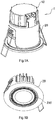
FIG. 1A is a perspective view of a preferred embodiment of the present invention. -
FIG. 1B is a perspective view illustrating part of the above preferred embodiment of the present invention. -
FIG. 2 is a sectional view of the above preferred embodiment of the present invention. -
FIG. 3 is an exploded view of the above preferred embodiment of the present invention. -
FIGs. 4A-4C illustrate installing modes of a sounding portion and a resonating cover according to the above preferred embodiment of the present invention. -
FIGs. 5A-5C illustrate mounting positions of the sounding portion and the resonating cover according to the above preferred embodiment of the present invention. - The following description is disclosed to enable any person skilled in the art to make and use the present invention. Preferred embodiments are provided in the following description only as examples and modifications will be apparent to those skilled in the art. The general principles defined in the following description would be applied to other embodiments, alternatives, modifications, equivalents, and applications without departing from the spirit and scope of the present invention.
- Referring to
Figs. 1-3 , a speaker lamp of the present invention is a cylinder down lamp, so as to be embedded to install. The speaker lamp 1 comprises aspeaker portion 10 and alamp body 20. Thespeaker portion 10 is detachably arranged on thelamp body 20. It allows the user to integrally embed the speaker lamp 1 into a mounting surface like ceiling and etc. Thespeaker portion 10 is located in the upper space of thelamp body 20, such that when the speaker lamp 1 is mounted and embedded into the mounting surface, both thespeaker portion 10 and thelamp body 20 are under the mounting surface, which can save installation space. The integral structure of thespeaker portion 10 and thelamp body 20 of the speaker lamp 1 according to the present invention is not only easier for the installation, but also more artistic after installation comparing to conventional separated speaker and lamp. Thespeaker portion 10 is arranged in the upper space of thelamp body 20, such that when thespeaker portion 10 is in a working state, it allows the sound generated to be transmitted to the external environment through thelamp body 20. The speaker lamp 1 can enhance the user experience and make the use of product more convenient and enjoyable for the user. Thespeaker portion 10 and thelamp body 20 are both designed to be detachable, which are easy to be replaced for the user. Once it is partially damaged during utilization, one may replace the damaged part that is needed to be replaced conveniently, rather than replace the entire of the speaker lamp 1. Hence, it lowers the cost of use thereof. - The
speaker portion 10 comprises a soundingportion 11, a resonatingcover 12, and asound collecting cover 13. The soundingportion 11 is disposed in the resonatingcover 12. Thelamp body 20 is disposed in thesound collecting cover 13. The soundingportion 11 is divides, in a sealed manner, the space defined by the resonatingcover 12 and thesound collecting cover 13 into the front sound chamber 100 and the rear sound chamber 200. The soundingportion 11 can generate sound in the front sound chamber 100 through vibrating in the front sound chamber 100. The sound will then be transmitted to the rear sound chamber 200 and be transmitted to the external environment through thelamp body 20 arranged in the rear sound chamber 200. It is worth mentioning that the soundingportion 11 has aninformation input terminal 110, which is able to receive audio signal for the soundingportion 11 to generate sound effect. Theinformation input terminal 110 allows directly insert of USB flash disk, memory card, or other storage devices and is able to read the audio information in the storage device. It is worth mentioning that the soundingportion 11 comprises a soundingelement 111 and aresonator 112. The soundingelement 111 is arranged in theresonator 112. Theresonator 112 is able to amplify the sound effect of the soundingelement 111. Preferably, the soundingelement 111 is a speaker, which can receive external audio signal and convert it into sound for transmission. - The resonating
cover 12 is a lid-like structure having awire hole 120 arranged thereon. Thewire hole 120 is located on the top of a side of the resonatingcover 12. The wire of the soundingportion 11 and thelamp body 20 can pass through thewire hole 120 to be connected to an external power source, so as to allow thespeaker portion 10 and thelamp body 20 to be in regular working states. It is worth mentioning that when the wire is penetrated from thewire hole 120, thewire hole 120 can be sealed, so as to keep the imperviousness of the resonatingcover 13 and enhance the sound effect of thespeaker portion 10. The sealing process is commonly conducted through adhesive or gel dispensing, coating, potting, deploying silicone element at thewire hole 120, and etc. - It is worth mentioning that the resonating
cover 12 further comprises apressure plate 121, wherein thewire hole 120 is positioned in the concave area of the resonatingcover 12 and thepressure plate 121 is able to match the concave area of the resonatingcover 12. When thepressure plate 121 is deployed in the resonatingcover 12, it can hold the wire that passes through thewire hole 120, so as to prevent the wire from being damaged and enhance both the imperviousness of the resonatingcover 12 and the sound effect of the speaker lamp 1. - The
sound collecting cover 13 is a hollow cylinder structure. Thelamp body 20 is detachably arranged in thesound collecting cover 13. Therefore, sound signal generated by the soundingportion 11 can be transmitted in thesound collecting cover 13. - It is worth mentioning that the
speaker portion 10 further comprises a connecting element 14, wherein the soundingportion 11 is arranged in the resonatingcover 12 through the connecting element 14. The soundingportion 11 and the resonatingcover 12 are connected imperviously. In other words, the soundingportion 11 is disposed in the space defined by the resonatingcover 12 and thesound collecting cover 13 through the connecting element 14. The soundingportion 11 is also divides, in a sealed manner, the space into the front sound chamber 100 and the rear sound chamber 200, so as to enhance the sound effect. - The connecting element 14 comprises a first connector 141 and a second connector 142. The resonating
cover 11 is detachably arranged on thesound collecting cover 13 through the first connector 141. The soundingportion 11 is disposed in the resonatingcover 12 through the second connector 142. The resonatingcover 11 is a lid-shaped structure. The soundingportion 11 can be arranged on the front, back or side of the resonatingcover 12 through the first connector 141. Different soundingportion 11 may be adaptable for different arranging direction on the resonatingcover 12, so as to allow thespeaker portion 10 to provide various sound effects. Preferably, referring toFigs. 4A-4C in order, the second connector 142 may be a connection means selected from the group consisting of buckle, screw, and adhesive, such that the soundingportion 11 can be arranged on the resonatingcover 12 easily. - Referring to
Figs. 5A-5C in order, the soundingportion 11 can be arranged in various directions on the front, back or side of the resonatingcover 12, which allows the user to decide and utilize different installing modes based on the actual needs, while the soundingportion 11 provides the same sound effect in the resonatingcover 12. It is worth mentioning that the front indicates that the soundingportion 11 being mounted in the resonatingcover 12 and the resonatingcover 12 is a lid structure, wherein the back refers to the top part of the resonatingcover 12 that after the resonating cover is installed, the soundingportion 11 faces toward the outside. - Preferably, the first connector 141 is a buckle connecting element, so as to allow the resonating
cover 12 to be detachably arranged on thesound collecting cover 13. The resonatingcover 12 and thesound collecting cover 13 are detachably connected, so as to provide a better usability thereof. Once the resonatingcover 12 or thesound collecting cover 13 is damaged during using, it only has to replace the damaged part rather than the entire device. Therefore, it not only lowers the maintenance costs for the user, but also facilitates the repairing job. - It is worth mentioning that the
speaker portion 10 further comprises a remote control 15, arranged in thelamp body 20. The user can wirelessly control the working states of thespeaker portion 10 and thelamp body 20 through the remote control 15. It includes controlling the volume and audio signal switching of thespeaker portion 10, controlling the brightness of thelamp body 20, and etc. The wireless controlling technique includes utilizing wireless technology, such as Bluetooth, Wi-Fi, Red tooth, and etc., to control thespeaker portion 10. The user may utilize a digital device, such as a cellphone, tablet, computer, and etc., to control the working state of the speaker lamp 1. The speaker lamp 1 may become smart, so as to enhance the user experience. - The remote control 15 comprises a
data transmission module 151 and acontrol module 152. Thedata transmission module 151 is electrically connected with thecontrol module 152. Thedata transmission module 151 is able to receive wireless transmission signals and transmit them to thecontrol module 152. Thecontrol module 152 is electrically connected to the soundingportion 11 and thelight emitting portion 22, so as to control the working states of the soundingportion 11 and thelight emitting portion 12. - The
lamp body 20 comprising abase 21, alight emitting portion 22 disposed on thebase 21, and alamp cover 23 arranged on the bottom surface of thebase 21. Light emitted by thelight emitting portion 22 is radiated through thelamp cover 23. Thebase 21 is arranged in thesound collecting cover 13, such that thelamp body 20 is arranged in thesound collecting cover 13 as well. - It is worth mentioning that the
base 21 comprises anunderframe 211 and a set of attachment ends 212. Thebase 211 is in a regular shape, which is preferably a circular structure. The attachment ends 212 are extended upward from theunderframe 211 and in a certain predetermined length. The attachment ends 212 are respectively form an L-shape with the underframe. The speaker lamp 1 can be mounted and embedded into a mounting surface, such as ceiling and etc., through the attachment ends 212. Thesound collecting cover 13 comprises a set ofopenings 130 provided thereon. The positions and shapes of theopenings 130 are corresponding to the attachment ends 212 respectively. When thesound collecting cover 13 is arranged on thebase 21, the attachment ends 212 can pass through theopenings 130 respectively and be affixed on the mounting surface. Thesound collecting cover 13 further comprises a set of sealingelements 131. The sealingelements 131 are correspondingly arranged on theopenings 130, so as to enhance the imperviousness of thesound collecting cover 13. - It is worth mentioning that the
lamp cover 23 comprises a set of sound bores 230. The sound bore 230 can be in various shapes, such as circular, square, oval, and etc. Therefore, sound generated by the soundingportion 11 can be transmitted to the external environment through the sound bore 230. - The
light emitting portion 22 comprises alens 222 and anilluminator 221 arranged on thelens 222. Thelens 222 can serve to condense the light, so as to make the light emitted by theilluminator 221 more even and uniform. When theilluminator 221 is in a working state, thelamp body 20 will also be in an illuminating state. - The
lamp body 20 further comprises afireproof element 24 arranged thereon, so as to reinforce the fireproof quality of thelamp body 20. In case of fire, thefireproof element 24 can serve to cut off the fire from passing through the opening of the speaker lamp 1 and spreading. It is worth mentioning that thefireproof element 24 comprises a firstfireproof element 241 and a secondfireproof element 242. The firstfireproof element 241 is arranged on theilluminator 221. The secondfireproof element 242 is arranged on thebase 21. Both the firstfireproof element 241 and the secondfireproof element 242 can serve to cut off fire spread. - The
lamp body 20 further comprises aradiator 25. Theradiator 25 can effectively dissipate heat generated by theilluminator 221 in working state, so as to protect theilluminator 221. It is worth mentioning that the fin and the top of theradiator 25 respectively have a predetermined curve, which are respectively in a curve shape. Based on experiments and tests, the curve structure facilitates sound transmission and enhances the sounding effect of thespeaker portion 10. - One skilled in the art will understand that the embodiment of the present invention as shown in the drawings and described above is exemplary only and not intended to be limiting. It will thus be seen that the objects of the present invention have been fully and effectively accomplished. The embodiments have been shown and described for the purposes of illustrating the functional and structural principles of the present invention and is subject to change without departure from such principles. Therefore, this invention includes all modifications encompassed within the spirit and scope of the following claims.
Claims (18)
- A speaker lamp, comprising:a speaker portion, comprising a sounding portion, a resonating cover, and a sound collecting cover, wherein said resonating cover and said sound collecting cover define a space therein, wherein said sounding portion is disposed in said resonating cover and divides, in a sealed manner, said space into a front sound chamber and a rear sound chamber; anda lamp body, comprising a base, a light emitting portion disposed on said base, and a lamp cover arranged on the bottom of said base, wherein said base is arranged in said sound collecting cover, wherein sound produced by said sounding portion passes through said lamp body to be transmitted to the external environment.
- The speaker lamp, as recited in claim 1, wherein said speaker portion comprises a connecting element, wherein said connecting element comprises a first connector, wherein said resonating cover is detachably arranged on said sound collecting cover through said first connector, wherein said resonating cover is provided on an upper space of said sound collecting cover.
- The speaker lamp, as recited in claim 2, wherein said connecting element further comprises a second connector, wherein said sounding portion is arranged on said resonating cover through said second connector.
- The speaker lamp, as recited in claim 1 or 3, wherein said base comprises an underframe and a set of attachment ends, wherein each said attachment end is extended outward from said underframe to form an L-shape with said underframe.
- The speaker lamp, as recited in claim 4, wherein said sound collecting cover comprises a set of openings provided thereon at the positions corresponding to said attachment ends respectively, wherein each said attachment end passes through corresponded said opening respectively.
- The speaker lamp, as recited in claim 5, wherein said sound collecting cover comprises a set of sealing elements, wherein said sealing elements are correspondingly arranged on said openings respectively, so as to enhance the imperviousness of the sound collecting cover.
- The speaker lamp, as recited in claim 6, wherein said light emitting portion comprises a lens and an illuminator arranged on said lens, wherein when said illuminator is in a working state, said lamp body will function to illuminate.
- The speaker lamp, as recited in claim 7, wherein said lamp body comprises a fireproof element, which further comprises a first fireproof element arranged on said lens and a second fireproof element arranged on said base.
- The speaker lamp, as recited in claim 1, wherein said lamp cover comprises a set of sound bores, evenly arranged on said lamp cover in predetermined angles.
- The speaker lamp, as recited in claim 1, wherein said sounding portion comprises a sounding element, wherein said sounding element comprises an information input terminal provided thereon for receiving wired or wireless audio signal.
- The speaker lamp, as recited in claim 1, wherein said speaker portion further comprises a remote control, wherein said remote control comprises a data transmission module deployed on said sounding portion and a control module respectively electrically connected with said sounding portion and said illuminator, wherein data transmission module is for receiving operation signal so as to control the working states of said sounding portion and said illuminator.
- The speaker lamp, as recited in claim 1, wherein said resonating cover comprises a wire hole arranged thereon and a wire, wherein said wire passes through said wire hole to be respectively electrically connected with said sounding portion and said illuminator, so as to allow said sounding portion and said illuminator to be connected to external power source.
- The speaker lamp, as recited in claim 12, wherein said resonating cover comprises a pressure plate, matchingly arranged on said resonating cover, so as to protect said wire passing through said wire hole and to enhance the imperviousness of said resonating cover.
- The speaker lamp, as recited in claim 1, wherein said sounding portion further comprises a resonator and a sounding element arranged on said resonator.
- The speaker lamp, as recited in claim 7, wherein said lamp body comprises a radiator, arranged on said illuminator, so as for dissipating heat generated by said illuminator.
- The speaker lamp, as recited in claim 15 wherein said radiator comprises at least a fin and a plurality of end portions arranged thereon, wherein both said fin and said end portions have a predetermined curve.
- The speaker lamp, as recited in claim 2 wherein said first connector is selected from the group consisting of adhesive, screw, and buckle.
- The speaker lamp, as recited in claim 3 wherein said second connector is a fastener.
Applications Claiming Priority (2)
| Application Number | Priority Date | Filing Date | Title |
|---|---|---|---|
| CN201620279899.XU CN205664230U (en) | 2016-04-05 | 2016-04-05 | Lamps and lanterns with audio |
| PCT/CN2017/074075 WO2017173888A1 (en) | 2016-04-05 | 2017-02-20 | Speaker lamp |
Publications (2)
| Publication Number | Publication Date |
|---|---|
| EP3447363A1 true EP3447363A1 (en) | 2019-02-27 |
| EP3447363A4 EP3447363A4 (en) | 2020-02-19 |
Family
ID=57163473
Family Applications (1)
| Application Number | Title | Priority Date | Filing Date |
|---|---|---|---|
| EP17778553.2A Withdrawn EP3447363A4 (en) | 2016-04-05 | 2017-02-20 | Speaker lamp |
Country Status (3)
| Country | Link |
|---|---|
| EP (1) | EP3447363A4 (en) |
| CN (1) | CN205664230U (en) |
| WO (1) | WO2017173888A1 (en) |
Families Citing this family (5)
| Publication number | Priority date | Publication date | Assignee | Title |
|---|---|---|---|---|
| CN205664230U (en) * | 2016-04-05 | 2016-10-26 | 佛山市威得士灯饰电器有限公司 | Lamps and lanterns with audio |
| CN206542540U (en) * | 2016-11-07 | 2017-10-03 | 佛山市威得士灯饰电器有限公司 | PA-system with lighting function |
| WO2019079968A1 (en) * | 2017-10-24 | 2019-05-02 | 佛山市威得士灯饰电器有限公司 | Embedded lamp with speaker device, speaker device and manufacturing method therefor |
| CN111246321B (en) * | 2020-02-26 | 2022-04-05 | 广州市高艺科技有限公司 | Light and sound co-installation device |
| CN112637713B (en) * | 2020-12-18 | 2022-11-22 | 正屋(厦门)电子有限公司 | Adjustable sound device of lamp and lamp using same |
Family Cites Families (7)
| Publication number | Priority date | Publication date | Assignee | Title |
|---|---|---|---|---|
| WO2010071102A1 (en) * | 2008-12-18 | 2010-06-24 | ティーオーエー株式会社 | Speaker with lighting fixture |
| KR100945849B1 (en) * | 2009-03-09 | 2010-03-05 | (주)기가바이트씨앤씨 | An illumination combined use schilling speaker |
| CN201611943U (en) * | 2009-12-31 | 2010-10-20 | 天津工程师范学院 | Loudspeaker audio cavity |
| CN102611972B (en) * | 2012-03-22 | 2015-03-25 | 蔡云萍 | Wireless speaker with LED (light-emitting diode) lighting function |
| CN204145688U (en) * | 2014-09-12 | 2015-02-04 | 寻乌县爱馨泰电子商贸有限公司 | Wall hanging loudspeaker |
| CN204420723U (en) * | 2014-12-29 | 2015-06-24 | 中山市毅龙五金实业有限公司 | A kind of flow-guiding type LED sound equipment Down lamp |
| CN205664230U (en) * | 2016-04-05 | 2016-10-26 | 佛山市威得士灯饰电器有限公司 | Lamps and lanterns with audio |
-
2016
- 2016-04-05 CN CN201620279899.XU patent/CN205664230U/en active Active
-
2017
- 2017-02-20 WO PCT/CN2017/074075 patent/WO2017173888A1/en active Application Filing
- 2017-02-20 EP EP17778553.2A patent/EP3447363A4/en not_active Withdrawn
Also Published As
| Publication number | Publication date |
|---|---|
| CN205664230U (en) | 2016-10-26 |
| WO2017173888A1 (en) | 2017-10-12 |
| EP3447363A4 (en) | 2020-02-19 |
Similar Documents
| Publication | Publication Date | Title |
|---|---|---|
| EP3447363A1 (en) | Speaker lamp | |
| US8299903B2 (en) | Screw-in LED light and sound bulb | |
| US7817016B2 (en) | Screw-in LED light and sound bulb | |
| US8013719B2 (en) | Combination low voltage speaker / light fixture | |
| CA2944636C (en) | Lighted mirror with sound system | |
| US9848265B2 (en) | LED lighting device and speaker | |
| TWI737593B (en) | Light and loudspeaker driver device | |
| US20190113220A1 (en) | Speaker Light Fixture | |
| US9739472B1 (en) | Dimmable and color temperature adjustable LED lamp with bluetooth audio playback function | |
| JP5861716B2 (en) | Light bulb type light source device | |
| US7784957B2 (en) | Recessed light fixture and speaker combination | |
| US8666104B2 (en) | Lighting and audio communication system | |
| US8172435B2 (en) | Methods and apparatus for ceiling mounted systems | |
| JP5713119B2 (en) | Light bulb type light source device | |
| US8300869B2 (en) | Lighting and audio communication system | |
| JP5699941B2 (en) | Light bulb type light source device | |
| WO2017120700A1 (en) | Intelligent downlight | |
| US20150153037A1 (en) | Combination led lamp and speakerphone assembly | |
| TW202001153A (en) | Lighting and speaker device and annular LED assembly | |
| CN104165312A (en) | LED Bluetooth music ceiling lamp | |
| JP2018056015A (en) | Lighting fixture | |
| KR100945849B1 (en) | An illumination combined use schilling speaker | |
| US20200217484A1 (en) | Lighting apparatus and related methods | |
| JP2013120728A (en) | Lighting device | |
| CN204592962U (en) | Music bulb |
Legal Events
| Date | Code | Title | Description |
|---|---|---|---|
| STAA | Information on the status of an ep patent application or granted ep patent |
Free format text: STATUS: THE INTERNATIONAL PUBLICATION HAS BEEN MADE |
|
| PUAI | Public reference made under article 153(3) epc to a published international application that has entered the european phase |
Free format text: ORIGINAL CODE: 0009012 |
|
| STAA | Information on the status of an ep patent application or granted ep patent |
Free format text: STATUS: REQUEST FOR EXAMINATION WAS MADE |
|
| 17P | Request for examination filed |
Effective date: 20190108 |
|
| AK | Designated contracting states |
Kind code of ref document: A1 Designated state(s): AL AT BE BG CH CY CZ DE DK EE ES FI FR GB GR HR HU IE IS IT LI LT LU LV MC MK MT NL NO PL PT RO RS SE SI SK SM TR |
|
| AX | Request for extension of the european patent |
Extension state: BA ME |
|
| STAA | Information on the status of an ep patent application or granted ep patent |
Free format text: STATUS: REQUEST FOR EXAMINATION WAS MADE |
|
| DAV | Request for validation of the european patent (deleted) | ||
| DAX | Request for extension of the european patent (deleted) | ||
| A4 | Supplementary search report drawn up and despatched |
Effective date: 20200116 |
|
| RIC1 | Information provided on ipc code assigned before grant |
Ipc: F21V 33/00 20060101AFI20200110BHEP Ipc: H04R 1/02 20060101ALI20200110BHEP Ipc: F21S 8/02 20060101ALI20200110BHEP Ipc: F21V 17/16 20060101ALI20200110BHEP Ipc: F21V 29/77 20150101ALN20200110BHEP Ipc: F21V 25/12 20060101ALN20200110BHEP |
|
| R17P | Request for examination filed (corrected) |
Effective date: 20181106 |
|
| RIN1 | Information on inventor provided before grant (corrected) |
Inventor name: WU, LIANGJU |
|
| RIC1 | Information provided on ipc code assigned before grant |
Ipc: F21V 29/77 20150101ALN20211021BHEP Ipc: F21V 25/12 20060101ALN20211021BHEP Ipc: H04R 1/02 20060101ALI20211021BHEP Ipc: F21V 17/16 20060101ALI20211021BHEP Ipc: F21S 8/02 20060101ALI20211021BHEP Ipc: F21V 33/00 20060101AFI20211021BHEP |
|
| GRAP | Despatch of communication of intention to grant a patent |
Free format text: ORIGINAL CODE: EPIDOSNIGR1 |
|
| STAA | Information on the status of an ep patent application or granted ep patent |
Free format text: STATUS: GRANT OF PATENT IS INTENDED |
|
| RIC1 | Information provided on ipc code assigned before grant |
Ipc: F21V 29/77 20150101ALN20211110BHEP Ipc: F21V 25/12 20060101ALN20211110BHEP Ipc: H04R 1/02 20060101ALI20211110BHEP Ipc: F21V 17/16 20060101ALI20211110BHEP Ipc: F21S 8/02 20060101ALI20211110BHEP Ipc: F21V 33/00 20060101AFI20211110BHEP |
|
| INTG | Intention to grant announced |
Effective date: 20211126 |
|
| STAA | Information on the status of an ep patent application or granted ep patent |
Free format text: STATUS: THE APPLICATION IS DEEMED TO BE WITHDRAWN |
|
| 18D | Application deemed to be withdrawn |
Effective date: 20220407 |