EP3447352A1 - Valve assembly for a turbo machine - Google Patents
Valve assembly for a turbo machine Download PDFInfo
- Publication number
- EP3447352A1 EP3447352A1 EP17187065.2A EP17187065A EP3447352A1 EP 3447352 A1 EP3447352 A1 EP 3447352A1 EP 17187065 A EP17187065 A EP 17187065A EP 3447352 A1 EP3447352 A1 EP 3447352A1
- Authority
- EP
- European Patent Office
- Prior art keywords
- valve
- valve seat
- cone
- steam
- arrangement
- Prior art date
- Legal status (The legal status is an assumption and is not a legal conclusion. Google has not performed a legal analysis and makes no representation as to the accuracy of the status listed.)
- Withdrawn
Links
Images


Classifications
-
- F—MECHANICAL ENGINEERING; LIGHTING; HEATING; WEAPONS; BLASTING
- F16—ENGINEERING ELEMENTS AND UNITS; GENERAL MEASURES FOR PRODUCING AND MAINTAINING EFFECTIVE FUNCTIONING OF MACHINES OR INSTALLATIONS; THERMAL INSULATION IN GENERAL
- F16K—VALVES; TAPS; COCKS; ACTUATING-FLOATS; DEVICES FOR VENTING OR AERATING
- F16K47/00—Means in valves for absorbing fluid energy
- F16K47/04—Means in valves for absorbing fluid energy for decreasing pressure or noise level, the throttle being incorporated in the closure member
-
- B—PERFORMING OPERATIONS; TRANSPORTING
- B22—CASTING; POWDER METALLURGY
- B22F—WORKING METALLIC POWDER; MANUFACTURE OF ARTICLES FROM METALLIC POWDER; MAKING METALLIC POWDER; APPARATUS OR DEVICES SPECIALLY ADAPTED FOR METALLIC POWDER
- B22F10/00—Additive manufacturing of workpieces or articles from metallic powder
- B22F10/20—Direct sintering or melting
- B22F10/28—Powder bed fusion, e.g. selective laser melting [SLM] or electron beam melting [EBM]
-
- F—MECHANICAL ENGINEERING; LIGHTING; HEATING; WEAPONS; BLASTING
- F16—ENGINEERING ELEMENTS AND UNITS; GENERAL MEASURES FOR PRODUCING AND MAINTAINING EFFECTIVE FUNCTIONING OF MACHINES OR INSTALLATIONS; THERMAL INSULATION IN GENERAL
- F16K—VALVES; TAPS; COCKS; ACTUATING-FLOATS; DEVICES FOR VENTING OR AERATING
- F16K1/00—Lift valves or globe valves, i.e. cut-off apparatus with closure members having at least a component of their opening and closing motion perpendicular to the closing faces
- F16K1/32—Details
- F16K1/34—Cutting-off parts, e.g. valve members, seats
- F16K1/36—Valve members
- F16K1/38—Valve members of conical shape
-
- F—MECHANICAL ENGINEERING; LIGHTING; HEATING; WEAPONS; BLASTING
- F16—ENGINEERING ELEMENTS AND UNITS; GENERAL MEASURES FOR PRODUCING AND MAINTAINING EFFECTIVE FUNCTIONING OF MACHINES OR INSTALLATIONS; THERMAL INSULATION IN GENERAL
- F16K—VALVES; TAPS; COCKS; ACTUATING-FLOATS; DEVICES FOR VENTING OR AERATING
- F16K1/00—Lift valves or globe valves, i.e. cut-off apparatus with closure members having at least a component of their opening and closing motion perpendicular to the closing faces
- F16K1/32—Details
- F16K1/34—Cutting-off parts, e.g. valve members, seats
- F16K1/42—Valve seats
-
- F—MECHANICAL ENGINEERING; LIGHTING; HEATING; WEAPONS; BLASTING
- F16—ENGINEERING ELEMENTS AND UNITS; GENERAL MEASURES FOR PRODUCING AND MAINTAINING EFFECTIVE FUNCTIONING OF MACHINES OR INSTALLATIONS; THERMAL INSULATION IN GENERAL
- F16K—VALVES; TAPS; COCKS; ACTUATING-FLOATS; DEVICES FOR VENTING OR AERATING
- F16K47/00—Means in valves for absorbing fluid energy
- F16K47/08—Means in valves for absorbing fluid energy for decreasing pressure or noise level and having a throttling member separate from the closure member, e.g. screens, slots, labyrinths
-
- B—PERFORMING OPERATIONS; TRANSPORTING
- B22—CASTING; POWDER METALLURGY
- B22F—WORKING METALLIC POWDER; MANUFACTURE OF ARTICLES FROM METALLIC POWDER; MAKING METALLIC POWDER; APPARATUS OR DEVICES SPECIALLY ADAPTED FOR METALLIC POWDER
- B22F2999/00—Aspects linked to processes or compositions used in powder metallurgy
-
- B—PERFORMING OPERATIONS; TRANSPORTING
- B22—CASTING; POWDER METALLURGY
- B22F—WORKING METALLIC POWDER; MANUFACTURE OF ARTICLES FROM METALLIC POWDER; MAKING METALLIC POWDER; APPARATUS OR DEVICES SPECIALLY ADAPTED FOR METALLIC POWDER
- B22F5/00—Manufacture of workpieces or articles from metallic powder characterised by the special shape of the product
- B22F5/06—Manufacture of workpieces or articles from metallic powder characterised by the special shape of the product of threaded articles, e.g. nuts
-
- B—PERFORMING OPERATIONS; TRANSPORTING
- B33—ADDITIVE MANUFACTURING TECHNOLOGY
- B33Y—ADDITIVE MANUFACTURING, i.e. MANUFACTURING OF THREE-DIMENSIONAL [3-D] OBJECTS BY ADDITIVE DEPOSITION, ADDITIVE AGGLOMERATION OR ADDITIVE LAYERING, e.g. BY 3-D PRINTING, STEREOLITHOGRAPHY OR SELECTIVE LASER SINTERING
- B33Y80/00—Products made by additive manufacturing
-
- Y—GENERAL TAGGING OF NEW TECHNOLOGICAL DEVELOPMENTS; GENERAL TAGGING OF CROSS-SECTIONAL TECHNOLOGIES SPANNING OVER SEVERAL SECTIONS OF THE IPC; TECHNICAL SUBJECTS COVERED BY FORMER USPC CROSS-REFERENCE ART COLLECTIONS [XRACs] AND DIGESTS
- Y02—TECHNOLOGIES OR APPLICATIONS FOR MITIGATION OR ADAPTATION AGAINST CLIMATE CHANGE
- Y02P—CLIMATE CHANGE MITIGATION TECHNOLOGIES IN THE PRODUCTION OR PROCESSING OF GOODS
- Y02P10/00—Technologies related to metal processing
- Y02P10/25—Process efficiency
Definitions
- the invention relates to a valve arrangement for flowing through a flow medium, comprising a valve cone and a valve housing with a valve seat, wherein the valve arrangement is formed with a valve inlet and a valve outlet, wherein the valve cone is formed movable against the valve seat and a fluidic connection between the valve inlet and the Valve outlet establishes when the valve plug is spaced from the valve seat and the fluidic connection is closed when the valve plug is in contact with the valve seat.
- the invention relates to a method for producing a valve arrangement.
- Valves are used, for example, in steam power plants in which a high temperature steam at high pressure is passed through steam lines.
- the steam is generated in steam generators and first led via the steam lines to a high-pressure turbine section and then to a reheater in the steam generator.
- the steam is brought to a higher temperature and then fed to a medium-pressure turbine section.
- the steam flows into a low-pressure turbine section and from there into a condenser.
- the vapor condenses on cooled condenser tubes. The resulting condensate is recycled via pumps to preheaters or to the steam generator.
- the object of the invention is therefore to change the valve so that the noise emission is reduced.
- a valve arrangement for flowing through a flow medium comprising a valve cone and a valve housing with a valve seat, wherein the valve arrangement is formed with a valve inlet and a valve outlet, wherein the valve cone is designed to be movable against the valve seat and a fluidic connection between the valve inlet and the valve outlet when the poppet is spaced from the valve seat and the fluidic connection is closed when the poppet is in contact with the valve seat, the poppet or valve seat or poppet and valve seat being formed with a flow surface substantially parallel to the valve seat deviates circular shape.
- the flow medium flowing through the valve assembly flows along the flow surface.
- Current valves are designed with smooth flow surfaces.
- the valve cone or the valve seat or the valve cone and the valve seat are circular.
- the invention now goes the way that the flow surface does not have a circular shape. Rather, the invention goes assume that the flow surface has a changed structure distributed along the circumference.
- the altered structure is characterized by having regular mountains and valleys in the circumferential direction. As a result, the shape of the flow surface is chevron-shaped.
- the flow surface may also have a serrated configuration. This means that the poppet affects the flow through its jagged formation.
- valve cone or the valve seat is formed with the flow surface according to the invention.
- the deviation from a circular shape relates to a flow surface which is located after the passage of the gap between the valve cone and the valve seat.
- the inventive design of the flow surface leads to a turbulence of the flow of the flow medium.
- the flow medium is a vapor.
- the region of the valve arrangement is thus manufactured downstream of the valve seat in such a way that it has the shape of a chevron nozzle or star-shaped or jagged nozzle in order to influence the jet disintegration and thereby the acoustic emission.
- the contour deviating from the circular shape can be introduced either in the valve cone, in the valve seat or in the valve cone and in the valve seat.
- the deviating from the circular shape geometry provides a targeted vortex formation, which increases the beam breakage and certain Schallmoden be dammed targeted.
- the advantage of the invention is that the noise emission is reduced by a faster jet breakup. Likewise, it is possible to selectively attenuate sound modes, which leads to a reduction of valve vibrations.
- the geometry of the invention must be located downstream of the seat, so that the valve can still close pressure-tight.
- the Chevron Nozzles generate vortex structures that contribute to faster jet breakup.
- the FIG. 1 shows a valve assembly 1 according to the prior art.
- the valve arrangement comprises a valve cone 2.
- the valve cone 2 is fastened to a valve spindle 3.
- the valve spindle 3 can be moved in the direction of movement 4.
- the valve assembly 1 further comprises a valve housing 5.
- the valve housing 5 is formed around the valve cone 2.
- the passage 6 of the valve stem 3 through the valve housing 5 is sealed.
- Within the valve housing 5 there is a steam space 7.
- the valve arrangement 1 further comprises a steam inlet 8 and a steam outlet 9.
- a vapor (preferably from the steam generator) flows through the steam inlet 8.
- the steam flows out of the valve arrangement 1 to, for example, a steam turbine.
- valve assembly 1 The amount of steam flowing through the valve assembly 1 from the steam inlet 8 to the steam outlet 9 is regulated by the position of the valve cone 2 to a valve seat 10.
- valve assembly 1 In the FIG. 1 the valve assembly 1 is shown in an open state. This is illustrated by the spacing of the valve cone 2 to the valve seat 10. In a closed state of the valve arrangement 1, the valve cone 2 would be arranged such that it touches the valve seat 10 is applied so that no steam from the steam chamber 7 can flow into the steam outlet 9.
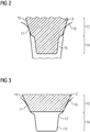
- the FIG. 2 shows an inventive arrangement of the valve cone 2.
- the FIG. 2 shows the arrangement of the valve plug 2 relative to the valve seat 10 in a closed state. This means that the valve cone 2 bears against the valve seat 10 at a contact line 11.
- the contact line 11 is circular in a cylindrical configuration of the valve cone 2. Other shapes of the valve cone 2, such as oval are also possible. Then, the contact line 11 would be an ellipse-like line as seen from above.
- the poppet 2 comprises a contact region 12.
- This contact region 12 of the poppet 2 has a substantially smooth flow surface 13.
- a steam flowing out of the steam inlet 8 thus flows on the smooth flow surface 13 in the direction of the steam outlet 9.
- the valve cone 2 comprises a downstream profile region 14. This profile region 14 is characterized in that it has a turbulence surface 15 which is opposite to the smooth surface Flow surface is not circular.
- the FIG. 2 shows a sectional view through the valve cone. 2
- FIG. 4 is a view from below of the poppet 2 to see.
- chevrons 17 are arranged, which have an influence on the steam flow.
- only one chevron is provided with the reference numeral 17.
- a serrated or star-shaped shape of the profile region 14 of the valve cone 2 may have.
- the number of spikes or chevrons can be adapted to the flow conditions.
- the FIG. 3 shows a way to arrange the profile area 14 in the region of the valve seat 10.
- the profile region 14 is executed in chevronförmiger, serrated or star-shaped design.
- the swirling surface 15 deviates substantially from the circular shape.
- the turbulence surface 15 leads to a turbulence of the flow.
- the swirling surface 15 is arranged after the passage of the vapor between the valve cone 2 and the valve seat 10. That is, the swirl surface 15 is located downstream to optimize swirling.
- the valve assembly 1 may be formed by an additive manufacturing process.
- the selective laser melting process offers.
Abstract
Die Erfindung betrifft eine Ventilanordnung (1) mit einem Ventilkegel (2) und einem Ventilsitz (10), wobei der Ventilkegel (2) und/oder der Ventilsitz (10) mit einer Chevronstruktur ausgebildet wird, um eine Verwirbelung des Strömungsmediums herbeizuführen, was zu einer Reduzierung der Schallemission führt.The invention relates to a valve arrangement (1) with a valve cone (2) and a valve seat (10), wherein the valve cone (2) and / or the valve seat (10) is formed with a chevron structure to induce a swirling of the flow medium, which a reduction of the noise emission leads.
Description
Die Erfindung betrifft eine Ventilanordnung zum Durchströmen eines Strömungsmediums, umfassend einen Ventilkegel und ein Ventilgehäuse mit einem Ventilsitz, wobei die Ventilanordnung mit einem Ventileinlass und einem Ventilauslass ausgebildet ist, wobei der Ventilkegel gegen den Ventilsitz bewegbar ausgebildet ist und eine strömungstechnische Verbindung zwischen dem Ventileinlass und dem Ventilauslass herstellt, wenn der Ventilkegel vom Ventilsitz beabstandet ist und die strömungstechnische Verbindung geschlossen ist, wenn der Ventilkegel am Ventilsitz berührend anliegt.The invention relates to a valve arrangement for flowing through a flow medium, comprising a valve cone and a valve housing with a valve seat, wherein the valve arrangement is formed with a valve inlet and a valve outlet, wherein the valve cone is formed movable against the valve seat and a fluidic connection between the valve inlet and the Valve outlet establishes when the valve plug is spaced from the valve seat and the fluidic connection is closed when the valve plug is in contact with the valve seat.
Desweiteren betrifft die Erfindung ein Verfahren zur Herstellung einer Ventilanordnung.Furthermore, the invention relates to a method for producing a valve arrangement.
Ventile werden beispielsweise in Dampfkraftanlagen eingesetzt, bei denen ein Dampf mit hoher Temperatur und einem hohen Druck durch Dampfleitungen geführt wird. In der Regel wird der Dampf in Dampferzeugern erzeugt und über die Dampfleitungen zunächst zu einer Hochdruck-Teilturbine geführt und anschließend zu einem Zwischenüberhitzer im Dampferzeuger. Im Zwischenüberhitzer wird der Dampf auf eine höhere Temperatur gebracht und danach zu einer Mitteldruck-Teilturbine geführt. Nach Durchströmen des Dampfes durch die Mitteldruck-Teilturbine strömt der Dampf in eine Niederdruck-Teilturbine und von dort in einen Kondensator. Im Kondensator kondensiert der Dampf an gekühlten Kondensatorrohren. Das somit entstandene Kondensat wird über Pumpen zu Vorwärmern bzw. zum Dampferzeuger wieder geführt.Valves are used, for example, in steam power plants in which a high temperature steam at high pressure is passed through steam lines. In general, the steam is generated in steam generators and first led via the steam lines to a high-pressure turbine section and then to a reheater in the steam generator. In the reheater, the steam is brought to a higher temperature and then fed to a medium-pressure turbine section. After flowing through the steam through the medium-pressure turbine section, the steam flows into a low-pressure turbine section and from there into a condenser. In the condenser, the vapor condenses on cooled condenser tubes. The resulting condensate is recycled via pumps to preheaters or to the steam generator.
Aufgrund der hohen Temperaturen und der hohen Drücke des Dampfes in den Dampfleitungen sind hohe Anforderungen an die Ventile gestellt. Insbesondere kommt es aufgrund von überkritischen Durchströmungen in den Ventilen zu vergleichsweise hohen Schallemissionen.Due to the high temperatures and the high pressures of the steam in the steam pipes high demands are placed on the valves. In particular, comparatively high sound emissions occur due to supercritical flows in the valves.
Es besteht ein Bedürfnis diese Schallemissionen zu reduzieren. Dies wird gegenwärtig dadurch erreicht, dass Schallisolierungsmaßnahmen durchgeführt werden. Allerdings sind solche Maßnahmen aufwändig und führen zu erhöhten Kosten.There is a need to reduce these noise emissions. This is currently achieved by performing soundproofing measures. However, such measures are complex and lead to increased costs.
Ein weiteres Problem ist, dass die im Ventil auftretenden Geschwindigkeiten des Dampfes zu einem Überschallstrahl führen können, was im Ventil zu Schwingungen führt. Solche Schwingungen können zu einer Schädigung des Ventils führen. Auch hier besteht ein Bedürfnis diese Schwingungen zu vermeiden.Another problem is that the vapor velocities occurring in the valve can lead to a supersonic jet, causing vibrations in the valve. Such vibrations can lead to damage to the valve. Again, there is a need to avoid these vibrations.
Aufgabe der Erfindung ist es daher, das Ventil derart zu ändern, dass die Schallemission reduziert wird.The object of the invention is therefore to change the valve so that the noise emission is reduced.
Gelöst wird diese Aufgabe durch eine Ventilanordnung zum Durchströmen eines Strömungsmediums, umfassend einen Ventilkegel und ein Ventilgehäuse mit einem Ventilsitz, wobei die Ventilanordnung mit einem Ventileinlass und einem Ventilauslass ausgebildet ist, wobei der Ventilkegel gegen den Ventilsitz bewegbar ausgebildet ist und eine strömungstechnische Verbindung zwischen dem Ventileinlass und dem Ventilauslass herstellt, wenn der Ventilkegel vom Ventilsitz beabstandet ist und die strömungstechnische Verbindung geschlossen ist, wenn der Ventilkegel am Ventilsitz berührend anliegt, wobei der Ventilkegel oder der Ventilsitz oder der Ventilkegel und der Ventilsitz mit einer Strömungsoberfläche ausgebildet sind, die von einer im wesentlichen kreisrunden Form abweicht.This object is achieved by a valve arrangement for flowing through a flow medium, comprising a valve cone and a valve housing with a valve seat, wherein the valve arrangement is formed with a valve inlet and a valve outlet, wherein the valve cone is designed to be movable against the valve seat and a fluidic connection between the valve inlet and the valve outlet when the poppet is spaced from the valve seat and the fluidic connection is closed when the poppet is in contact with the valve seat, the poppet or valve seat or poppet and valve seat being formed with a flow surface substantially parallel to the valve seat deviates circular shape.
Das durch die Ventilanordnung strömende Strömungsmedium strömt an der Strömungsoberfläche entlang. Derzeitige Ventile sind mit glatten Strömungsoberflächen ausgebildet. In der Regel sind der Ventilkegel oder der Ventilsitz oder der Ventilkegel und der Ventilsitz kreisrund ausgebildet.The flow medium flowing through the valve assembly flows along the flow surface. Current valves are designed with smooth flow surfaces. In general, the valve cone or the valve seat or the valve cone and the valve seat are circular.
Die Erfindung geht nun den Weg, dass die Strömungsoberfläche keine kreisrunde Form aufweist. Vielmehr geht die Erfindung davon aus, dass die Strömungsoberfläche eine entlang des Umfangs verteilte geänderte Struktur aufweist. Die geänderte Struktur ist dadurch charakterisiert, dass sie regelmäßige Berge und Täler in Umfangsrichtung aufweist. Dadurch ist die Gestalt der Strömungsoberfläche chevronförmig ausgebildet.The invention now goes the way that the flow surface does not have a circular shape. Rather, the invention goes assume that the flow surface has a changed structure distributed along the circumference. The altered structure is characterized by having regular mountains and valleys in the circumferential direction. As a result, the shape of the flow surface is chevron-shaped.
Erfindungsgemäß kann die Strömungsoberfläche auch eine zackenförmige Gestaltung aufweisen. Das bedeutet, dass der Ventilkegel die Strömung durch seine zackenförmige Ausbildung beeinflusst.According to the invention, the flow surface may also have a serrated configuration. This means that the poppet affects the flow through its jagged formation.
Ebenso denkbar ist eine sternförmige Ausbildung der Strömungsoberfläche.Also conceivable is a star-shaped design of the flow surface.
Selbstverständlich ist nicht der komplette Ventilkegel oder der Ventilsitz mit der erfindungsgemäßen Strömungsoberfläche ausgebildet. Die Abweichung von einer kreisrunden Form betrifft eine Strömungsoberfläche, die nach der Durchströmung des Zwischenraumes zwischen dem Ventilkegel und dem Ventilsitz sich befindet.Of course, not the complete valve cone or the valve seat is formed with the flow surface according to the invention. The deviation from a circular shape relates to a flow surface which is located after the passage of the gap between the valve cone and the valve seat.
Die erfindungsgemäße Ausgestaltung der Strömungsoberfläche führt zu einer Verwirbelung der Strömung des Strömungsmediums.The inventive design of the flow surface leads to a turbulence of the flow of the flow medium.
Im Falle einer Dampfturbinenventilanordnung ist das Strömungsmedium ein Dampf.In the case of a steam turbine valve arrangement, the flow medium is a vapor.
Erfindungsgemäß wird somit stromab des Ventilsitzes der Bereich der Ventilanordnung derart gefertigt, dass er die Form einer Chevrondüse bzw. sternförmigen oder zackigen Düse aufweist, um den Strahlzerfall und dadurch die Schallemission zu beeinflussen. Die von der kreisrunden Form abweichende Kontur kann entweder im Ventilkegel, im Ventilsitz oder auch im Ventilkegel und im Ventilsitz eingebracht werden. Die von der kreisrunden Form abweichende Geometrie sorgt für eine gezielte Wirbelbildung, wodurch der Strahlzerfall gesteigert und gewisse Schallmoden gezielt herausgedämpft werden.According to the invention, the region of the valve arrangement is thus manufactured downstream of the valve seat in such a way that it has the shape of a chevron nozzle or star-shaped or jagged nozzle in order to influence the jet disintegration and thereby the acoustic emission. The contour deviating from the circular shape can be introduced either in the valve cone, in the valve seat or in the valve cone and in the valve seat. The deviating from the circular shape geometry provides a targeted vortex formation, which increases the beam breakage and certain Schallmoden be dammed targeted.
Der Vorteil der Erfindung liegt darin, dass die Schallemission durch einen schnelleren Strahlzerfall verringert wird. Ebenso ist es möglich, gezielt Schallmoden zu dämpfen, was zu einer Reduktion von Ventilschwingungen führt.The advantage of the invention is that the noise emission is reduced by a faster jet breakup. Likewise, it is possible to selectively attenuate sound modes, which leads to a reduction of valve vibrations.
Selbstverständlich muss die erfindungsgemäße Geometrie stromab der Sitzfläche angeordnet werden, damit das Ventil noch druckdicht schließen kann.Of course, the geometry of the invention must be located downstream of the seat, so that the valve can still close pressure-tight.
Durch die Chevrondüsen werden Wirbelstrukturen erzeugt, die zum schnelleren Strahlzerfall beitragen.The Chevron Nozzles generate vortex structures that contribute to faster jet breakup.
Erfindungsgemäß wird vorgeschlagen die Anzahl und Größe der Zacken durch Berechnungsmethoden anzupassen, um Wirbelsysteme gezielt zu erzeugen, so dass unerwünschte akustische Moden herausgedämpft werden können.According to the invention, it is proposed to adapt the number and size of the prongs by calculation methods in order to generate eddy systems in a targeted manner, so that unwanted acoustic modes can be damped out.
Die oben beschriebenen Eigenschaften, Merkmale und Vorteile dieser Erfindung sowie die Art und Weise, wie diese erreicht werden, werden klarer und deutlicher verständlich im Zusammenhang mit der folgenden Beschreibung der Ausführungsbeispiele, die im Zusammenhang mit den Zeichnungen näher erläutert werden.The above-described characteristics, features, and advantages of this invention, as well as the manner in which they will be achieved, will become clearer and more clearly understood in connection with the following description of the embodiments, which will be described in detail in conjunction with the drawings.
Gleiche Bauteile oder Bauteile mit gleicher Funktion sind dabei mit gleichen Bezugszeichen gekennzeichnet.Identical components or components with the same function are identified by the same reference numerals.
Ausführungsbeispiele der Erfindung werden nachfolgend anhand der Zeichnungen beschrieben. Diese soll die Ausführungsbeispiele nicht maßgeblich darstellen, vielmehr ist die Zeichnung, wo zur Erläuterungen dienlich, in schematisierter und/oder leicht verzerrter Form ausgeführt.Embodiments of the invention will be described below with reference to the drawings. This is not intended to represent the embodiments significantly, but the drawing, where appropriate for explanations, executed in a schematized and / or slightly distorted form.
Im Hinblick auf Ergänzungen der in der Zeichnung unmittelbar erkennbaren Lehren, wird auf den einschlägigen Stand der Technik verwiesen.With regard to additions to the teachings directly recognizable in the drawing, reference is made to the relevant prior art.
Es zeigen
- Figur 1
- eine schematische Darstellung einer Ventilanordnung nach dem Stand der Technik,
Figur 2- eine Schnittansicht durch eine erfindungsgemäße Struktur einer Ventilanordnung,
Figur 3- eine Schnittansicht einer erfindungsgemäßen alternativen Struktur der Erfindung,
- Figur 4
- eine Draufsicht auf einen erfindungsgemäßen Ventilkegel.
- FIG. 1
- a schematic representation of a valve arrangement according to the prior art,
- FIG. 2
- a sectional view through an inventive structure of a valve assembly,
- FIG. 3
- a sectional view of an alternative structure of the invention according to the invention,
- FIG. 4
- a plan view of a valve cone according to the invention.
Die
Die Menge des Dampfes, der durch die Ventilanordnung 1 vom Dampfeinlass 8 zum Dampfauslass 9 strömt, wird durch die Stellung des Ventilkegels 2 zu einem Ventilsitz 10 geregelt. In der
Die
In
In einer alternativen Ausführungsform kann statt eines Chevrons 17 eine zackenförmige oder eine sternförmige Gestalt des Profilbereichs 14 des Ventilkegels 2 aufweisen.In an alternative embodiment, instead of a
Die Anzahl der Zacken bzw. Chevrons kann an die Strömungsbedingungen angepasst werden.The number of spikes or chevrons can be adapted to the flow conditions.
Die
Die Ventilanordnung 1 kann nach einem additiven Fertigungsverfahren ausgebildet werden. Dazu bietet sich das selektive Laserschmelzverfahren an.The valve assembly 1 may be formed by an additive manufacturing process. For this purpose, the selective laser melting process offers.
Obwohl die Erfindung im Detail durch das bevorzugte Ausführungsbeispiel näher illustriert und beschrieben wurde, so ist die Erfindung nicht durch die offenbarten Beispiele eingeschränkt und andere Variationen können vom Fachmann hieraus abgeleitet werden, ohne den Schutzumfang der Erfindung zu verlassen.Although the invention has been further illustrated and described in detail by the preferred embodiment, the invention is not limited by the disclosed examples, and other variations can be derived therefrom by those skilled in the art without departing from the scope of the invention.
Claims (7)
einen Ventilkegel (2) und
ein Ventilgehäuse (5) mit einem Ventilsitz (10),
wobei die Ventilanordnung (1) mit einem Ventileinlass (8) und einem Ventilauslass (9) ausgebildet ist,
wobei der Ventilkegel (2) gegen den Ventilsitz (10) bewegbar ausgebildet ist und eine strömungstechnische Verbindung zwischen dem Ventileinlass (8) und dem Ventilauslass (9) herstellt, wenn der Ventilkegel (2) vom Ventilsitz (10) beabstandet ist und die strömungstechnische Verbindung geschlossen ist, wenn der Ventilkegel (2) am Ventilsitz (10) berührend anliegt,
dadurch gekennzeichnet, dass
der Ventilkegel (2) oder der Ventilsitz (10) oder der Ventilkegel (2) und der Ventilsitz (10) mit einer Verwirbelungsoberfläche (15) ausgebildet sind, die von einer im wesentlichen kreisrunden Form abweicht.Valve arrangement (1) for flowing through a flow medium, comprising
a poppet (2) and
a valve housing (5) having a valve seat (10),
wherein the valve assembly (1) is formed with a valve inlet (8) and a valve outlet (9),
wherein the poppet (2) is movably formed against the valve seat (10) and establishes a fluidic connection between the valve inlet (8) and the valve outlet (9) when the poppet (2) is spaced from the valve seat (10) and the fluidic connection is closed, when the valve cone (2) on the valve seat (10) is in contact,
characterized in that
the valve cone (2) or the valve seat (10) or the valve cone (2) and the valve seat (10) are formed with a swirling surface (15) deviating from a substantially circular shape.
wobei die Verwirbelungsoberfläche (15) chevronförmig ausgebildet ist.Valve arrangement (1) according to claim 1,
wherein the swirling surface (15) is chevron-shaped.
wobei die Verwirbelungsoberfläche (15) zackenförmig ausgebildet ist.Valve arrangement (1) according to claim 1 or 2,
wherein the swirling surface (15) is serrated.
wobei die Verwirbelungsoberfläche (15) sternförmig ausgebildet ist.Valve arrangement (1) according to one of the preceding claims,
wherein the swirling surface (15) is star-shaped.
wobei die Verwirbelungsoberfläche zu einer Verwirbelung der Strömung nach Beabstandung des Ventilkegels (2) vom Ventilsitz (10) führt.Valve arrangement (1) according to one of the preceding claims,
wherein the swirling surface causes turbulence of the flow after spacing the poppet (2) from the valve seat (10) leads.
wobei der Ventilkegel (2) oder der Ventilsitz (10) oder der Ventilkegel (2) und der Ventilsitz (10) mittels eines additiven Fertigungsverfahrens ausgebildet werden.Method for producing a valve arrangement (1) according to one of the preceding claims,
wherein the valve plug (2) or the valve seat (10) or the valve plug (2) and the valve seat (10) are formed by means of an additive manufacturing process.
wobei als additives Fertigungsverfahren das selektive Laserschmelzen verwendet wird.Method according to claim 6,
wherein as additive manufacturing process, the selective laser melting is used.
Priority Applications (1)
| Application Number | Priority Date | Filing Date | Title |
|---|---|---|---|
| EP17187065.2A EP3447352A1 (en) | 2017-08-21 | 2017-08-21 | Valve assembly for a turbo machine |
Applications Claiming Priority (1)
| Application Number | Priority Date | Filing Date | Title |
|---|---|---|---|
| EP17187065.2A EP3447352A1 (en) | 2017-08-21 | 2017-08-21 | Valve assembly for a turbo machine |
Publications (1)
| Publication Number | Publication Date |
|---|---|
| EP3447352A1 true EP3447352A1 (en) | 2019-02-27 |
Family
ID=59677133
Family Applications (1)
| Application Number | Title | Priority Date | Filing Date |
|---|---|---|---|
| EP17187065.2A Withdrawn EP3447352A1 (en) | 2017-08-21 | 2017-08-21 | Valve assembly for a turbo machine |
Country Status (1)
| Country | Link |
|---|---|
| EP (1) | EP3447352A1 (en) |
Citations (8)
| Publication number | Priority date | Publication date | Assignee | Title |
|---|---|---|---|---|
| US3187775A (en) * | 1961-08-21 | 1965-06-08 | Shaffer Tool Works | Flow bean |
| NL8602008A (en) * | 1986-08-06 | 1988-03-01 | Grontmij N V | Valve assembly for limiting flow through liq. pipe - has valve member with grooved surface, central venturi passage and peripheral channel moved by flow pressure in housing against spring |
| US6082405A (en) * | 1996-07-09 | 2000-07-04 | Tac Ab | Valve cone, a valve and a valve manufacturing process |
| DE10146941A1 (en) * | 2001-09-24 | 2003-04-10 | Gen Motors Corp | Fluid valve, as a proportional valve for fuel cell systems, has a structured flow channel at the sealing seat and valve head, with the housing, to control and/or switch low mass flows and switch large mass flows |
| WO2009027810A2 (en) * | 2007-08-31 | 2009-03-05 | Enologica Friulana S.A.S | Self-cleaning nozzle for flotation clarifiers |
| US20150233493A1 (en) * | 2012-09-17 | 2015-08-20 | Paal Irgens HAGEVIK | Device to Reduce the Pressure of a Liquid Flow and a Regulating Valve |
| WO2016133497A1 (en) * | 2015-02-17 | 2016-08-25 | Halliburton Energy Services, Inc. | 3d printed flapper valve |
| US20160369905A1 (en) * | 2013-07-23 | 2016-12-22 | Kyb Corporation | Control valve |
-
2017
- 2017-08-21 EP EP17187065.2A patent/EP3447352A1/en not_active Withdrawn
Patent Citations (8)
| Publication number | Priority date | Publication date | Assignee | Title |
|---|---|---|---|---|
| US3187775A (en) * | 1961-08-21 | 1965-06-08 | Shaffer Tool Works | Flow bean |
| NL8602008A (en) * | 1986-08-06 | 1988-03-01 | Grontmij N V | Valve assembly for limiting flow through liq. pipe - has valve member with grooved surface, central venturi passage and peripheral channel moved by flow pressure in housing against spring |
| US6082405A (en) * | 1996-07-09 | 2000-07-04 | Tac Ab | Valve cone, a valve and a valve manufacturing process |
| DE10146941A1 (en) * | 2001-09-24 | 2003-04-10 | Gen Motors Corp | Fluid valve, as a proportional valve for fuel cell systems, has a structured flow channel at the sealing seat and valve head, with the housing, to control and/or switch low mass flows and switch large mass flows |
| WO2009027810A2 (en) * | 2007-08-31 | 2009-03-05 | Enologica Friulana S.A.S | Self-cleaning nozzle for flotation clarifiers |
| US20150233493A1 (en) * | 2012-09-17 | 2015-08-20 | Paal Irgens HAGEVIK | Device to Reduce the Pressure of a Liquid Flow and a Regulating Valve |
| US20160369905A1 (en) * | 2013-07-23 | 2016-12-22 | Kyb Corporation | Control valve |
| WO2016133497A1 (en) * | 2015-02-17 | 2016-08-25 | Halliburton Energy Services, Inc. | 3d printed flapper valve |
Similar Documents
| Publication | Publication Date | Title |
|---|---|---|
| DE102004022063A1 (en) | Exhaust gas diffuser for an axial flow turbine | |
| EP2233836A1 (en) | Swirler, method for reducing flashback in a burner with at least one swirler and burner | |
| DE10054244C2 (en) | Turbine blade arrangement and turbine blade for an axial turbine | |
| DE102010037862A1 (en) | Whirl chambers for slit flow control | |
| DE102009059318A1 (en) | Methods, systems and / or devices associated with steam turbine exhaust diffusers | |
| EP2505808B1 (en) | Device for mixing fuel and air of a turbojet engine | |
| CH698570B1 (en) | Fuel nozzle for a combustor. | |
| DE102020115426A1 (en) | Valve trimmer for use with valves | |
| DE102014221049A1 (en) | Arrangement and method for blowing off compressor air in an engine | |
| DE102016213551A1 (en) | Nozzle for water, in particular for a water cannon | |
| DE2447100C2 (en) | Internal combustion engine with supercharging according to the surge process | |
| DE102018119730A1 (en) | Improved fluid lines | |
| EP3019793B1 (en) | Heat-protective insert for a fuel line | |
| EP3447352A1 (en) | Valve assembly for a turbo machine | |
| EP3793807B1 (en) | Gasket for sealing a gap between two exhaust gas containing pipes | |
| EP1153219B1 (en) | Diffuser without pulsation of the impact interface and method for suppressing impact interface pulsation of diffusers | |
| EP0035605A1 (en) | Excluding device for gaseous media comprising an equipment for damping of selfexciting acoustic vibrations in cavities | |
| DE2545378A1 (en) | GAS PRESSURE REGULATOR | |
| WO2011128179A1 (en) | Swirl generator for a torch | |
| WO2000034714A1 (en) | Combustion device and method for burning a fuel | |
| DE112015004881B4 (en) | Main steam valve and steam turbine | |
| DE2628704A1 (en) | DRAIN DEVICE FOR EMPTYING A CONTAINER CONTAINING A FLUID UNDER PRESSURE | |
| EP3296523A1 (en) | Assembly for splititng a mass flow in two partial mass flows | |
| DE102017104044A1 (en) | Method for producing a fuel or hydraulic fluid unit with introduction of a protective medium and machine tool | |
| EP2730772A2 (en) | Nozzle with baffles |
Legal Events
| Date | Code | Title | Description |
|---|---|---|---|
| PUAI | Public reference made under article 153(3) epc to a published international application that has entered the european phase |
Free format text: ORIGINAL CODE: 0009012 |
|
| AK | Designated contracting states |
Kind code of ref document: A1 Designated state(s): AL AT BE BG CH CY CZ DE DK EE ES FI FR GB GR HR HU IE IS IT LI LT LU LV MC MK MT NL NO PL PT RO RS SE SI SK SM TR |
|
| AX | Request for extension of the european patent |
Extension state: BA ME |
|
| STAA | Information on the status of an ep patent application or granted ep patent |
Free format text: STATUS: THE APPLICATION IS DEEMED TO BE WITHDRAWN |
|
| 18D | Application deemed to be withdrawn |
Effective date: 20190828 |