EP3447296A1 - Compressor - Google Patents
Compressor Download PDFInfo
- Publication number
- EP3447296A1 EP3447296A1 EP17843391.8A EP17843391A EP3447296A1 EP 3447296 A1 EP3447296 A1 EP 3447296A1 EP 17843391 A EP17843391 A EP 17843391A EP 3447296 A1 EP3447296 A1 EP 3447296A1
- Authority
- EP
- European Patent Office
- Prior art keywords
- muffler
- muffler body
- compression mechanism
- refrigerant
- cavity
- Prior art date
- Legal status (The legal status is an assumption and is not a legal conclusion. Google has not performed a legal analysis and makes no representation as to the accuracy of the status listed.)
- Withdrawn
Links
- 230000006835 compression Effects 0.000 claims abstract description 45
- 238000007906 compression Methods 0.000 claims abstract description 45
- 230000010349 pulsation Effects 0.000 claims abstract description 39
- 239000012530 fluid Substances 0.000 claims abstract description 15
- 230000002093 peripheral effect Effects 0.000 claims description 25
- 239000003507 refrigerant Substances 0.000 abstract description 51
- 238000007599 discharging Methods 0.000 abstract 1
- 230000000694 effects Effects 0.000 description 12
- 238000005192 partition Methods 0.000 description 4
- 230000007423 decrease Effects 0.000 description 2
- 230000005855 radiation Effects 0.000 description 2
- 229910000838 Al alloy Inorganic materials 0.000 description 1
- 238000010521 absorption reaction Methods 0.000 description 1
- 230000002238 attenuated effect Effects 0.000 description 1
- 239000007788 liquid Substances 0.000 description 1
- 239000007769 metal material Substances 0.000 description 1
Images


Classifications
-
- F—MECHANICAL ENGINEERING; LIGHTING; HEATING; WEAPONS; BLASTING
- F04—POSITIVE - DISPLACEMENT MACHINES FOR LIQUIDS; PUMPS FOR LIQUIDS OR ELASTIC FLUIDS
- F04B—POSITIVE-DISPLACEMENT MACHINES FOR LIQUIDS; PUMPS
- F04B39/00—Component parts, details, or accessories, of pumps or pumping systems specially adapted for elastic fluids, not otherwise provided for in, or of interest apart from, groups F04B25/00 - F04B37/00
-
- F—MECHANICAL ENGINEERING; LIGHTING; HEATING; WEAPONS; BLASTING
- F04—POSITIVE - DISPLACEMENT MACHINES FOR LIQUIDS; PUMPS FOR LIQUIDS OR ELASTIC FLUIDS
- F04C—ROTARY-PISTON, OR OSCILLATING-PISTON, POSITIVE-DISPLACEMENT MACHINES FOR LIQUIDS; ROTARY-PISTON, OR OSCILLATING-PISTON, POSITIVE-DISPLACEMENT PUMPS
- F04C23/00—Combinations of two or more pumps, each being of rotary-piston or oscillating-piston type, specially adapted for elastic fluids; Pumping installations specially adapted for elastic fluids; Multi-stage pumps specially adapted for elastic fluids
- F04C23/008—Hermetic pumps
-
- F—MECHANICAL ENGINEERING; LIGHTING; HEATING; WEAPONS; BLASTING
- F04—POSITIVE - DISPLACEMENT MACHINES FOR LIQUIDS; PUMPS FOR LIQUIDS OR ELASTIC FLUIDS
- F04C—ROTARY-PISTON, OR OSCILLATING-PISTON, POSITIVE-DISPLACEMENT MACHINES FOR LIQUIDS; ROTARY-PISTON, OR OSCILLATING-PISTON, POSITIVE-DISPLACEMENT PUMPS
- F04C23/00—Combinations of two or more pumps, each being of rotary-piston or oscillating-piston type, specially adapted for elastic fluids; Pumping installations specially adapted for elastic fluids; Multi-stage pumps specially adapted for elastic fluids
-
- F—MECHANICAL ENGINEERING; LIGHTING; HEATING; WEAPONS; BLASTING
- F04—POSITIVE - DISPLACEMENT MACHINES FOR LIQUIDS; PUMPS FOR LIQUIDS OR ELASTIC FLUIDS
- F04C—ROTARY-PISTON, OR OSCILLATING-PISTON, POSITIVE-DISPLACEMENT MACHINES FOR LIQUIDS; ROTARY-PISTON, OR OSCILLATING-PISTON, POSITIVE-DISPLACEMENT PUMPS
- F04C29/00—Component parts, details or accessories of pumps or pumping installations, not provided for in groups F04C18/00 - F04C28/00
- F04C29/06—Silencing
-
- F—MECHANICAL ENGINEERING; LIGHTING; HEATING; WEAPONS; BLASTING
- F04—POSITIVE - DISPLACEMENT MACHINES FOR LIQUIDS; PUMPS FOR LIQUIDS OR ELASTIC FLUIDS
- F04C—ROTARY-PISTON, OR OSCILLATING-PISTON, POSITIVE-DISPLACEMENT MACHINES FOR LIQUIDS; ROTARY-PISTON, OR OSCILLATING-PISTON, POSITIVE-DISPLACEMENT PUMPS
- F04C29/00—Component parts, details or accessories of pumps or pumping installations, not provided for in groups F04C18/00 - F04C28/00
- F04C29/06—Silencing
- F04C29/061—Silencers using overlapping frequencies, e.g. Helmholtz resonators
-
- F—MECHANICAL ENGINEERING; LIGHTING; HEATING; WEAPONS; BLASTING
- F04—POSITIVE - DISPLACEMENT MACHINES FOR LIQUIDS; PUMPS FOR LIQUIDS OR ELASTIC FLUIDS
- F04C—ROTARY-PISTON, OR OSCILLATING-PISTON, POSITIVE-DISPLACEMENT MACHINES FOR LIQUIDS; ROTARY-PISTON, OR OSCILLATING-PISTON, POSITIVE-DISPLACEMENT PUMPS
- F04C29/00—Component parts, details or accessories of pumps or pumping installations, not provided for in groups F04C18/00 - F04C28/00
- F04C29/06—Silencing
- F04C29/065—Noise dampening volumes, e.g. muffler chambers
Definitions
- the present invention relates to a compressor having a muffler which reduces a pressure variation (pulsation) of a compressed fluid.
- a rotary compressor constituting an air conditioner or the like includes a compression mechanism which compresses a refrigerant in a cylinder by a rotation of a piston rotor and a muffler which suppresses noise caused by a pressure variation of the compressed refrigerant.
- a two-stage muffler having a first muffler and a second muffler is adopted (for example, PTL 1).
- the compressed refrigerant is discharged from a discharge port of a bearing to which the cylinder is fixed into the first muffler, and is discharged from the inside of the first muffler into the second muffler through a discharge opening of the first muffler.
- a space in the first muffler and a space in the second muffler are operated as a resistance according to a space volume by the compressed refrigerant, and thus, the compressed refrigerant sequentially passes through the first muffler and the second muffler, and the pulsation of the refrigerant is reduced.
- an object of the present invention is to provide a compressor capable of sufficiently reducing an appropriate pulsation frequency component of a fluid by a muffler while securing performance of the compressor.
- a compressor including: a compression mechanism which compresses a fluid; and a muffler which reduces a pulsation of the fluid compressed by the compression mechanism, in which the muffler includes a muffler body which receives the fluid from the compression mechanism into an inside of the muffler body, and a cover which forms a cavity between an outer peripheral portion of the muffler body and the cover and discharges the fluid received from the inside of the muffler body, the muffler body includes a plurality of openings which are formed to penetrate the muffler body in a plate thickness direction, separately from a discharge opening through which the fluid passes from the inside of the muffler body into the cavity, and sound is absorbed by establishing a Helmholtz resonance with respect to an air mass existing inside each opening communicating with the cavity from a relationship between a speed of sound C, a cross-sectional area S of each of the openings, a plate thickness L, and a volume V of
- the compression mechanism includes a piston rotor which is provided in a rotary shaft and a cylinder in which the piston rotor is disposed, and the muffler body and the cover are disposed around an axis of the rotary shaft.
- a pulsation reduction effect based on the Helmholtz resonance can be obtained while the pulsation reduction effect is maintained by a two-stage muffler which repeats discharge of pulsation into a space.
- a movement of the air mass inside the minute opening of the muffler body generating the Helmholtz resonance does not affect a mainstream inside the muffler, and thus, the pulsation of the fluid is sufficiently reduced and the sound is absorbed while the performance of the compressor is secured, and it is possible to suppress a noise caused by a pressure variation of the fluid.
- the muffler itself becomes a sound source by the pulsation reduction and can suppress radiation of the sound pressure, and thus, even if a plate thickness of the muffler body or the cover is thin, it is possible to suppress the noise.
- a rotary type compressor 1 shown in Fig. 1 sucks a gas refrigerant in an accumulator (gas-liquid separator) (not shown) through pipes 8 and 9 and compresses the gas refrigerant by a compression mechanism 4.
- the compressor 1 and the accumulator constitute a refrigerating cycle device such as an air conditioner or a refrigerator and are connected to a refrigerant circuit (not shown) through which the refrigerant circulates.
- the compressor 1 includes a motor 2 which is a power source, a rotary shaft 3 (crank shaft) which is rotated by a rotational driving force output from the motor 2, the rotary type compression mechanism 4 which is driven by the rotational driving force transmitted via the rotary shaft 3, mufflers 10 and 20 which are disposed around an axis of the rotary shaft 3, and a housing 5.
- the mufflers 10 and 20 suppress a noise caused by a pulsation of the refrigerant compressed by the compression mechanism 4.
- the housing 5 accommodates the motor 2, the rotary shaft 3, the compression mechanism 4, and the mufflers 10 and 20, and is formed in a cylindrical shape.
- the motor 2 includes a stator 2A which is fixed to an inner peripheral portion of the housing 5, and a rotor 2B which is disposed inside the stator 2A.
- the rotor 2B rotates with respect to the stator 2A by supplying power to a coil 2C provided in the stator 2A.
- the rotary shaft 3 includes a main shaft portion 3A which is connected to the rotor 2B and protrudes downward from the rotor 2B, an upper crank pin 3B which is eccentric to an axis center of the main shaft portion 3A, and a lower crank pin 3C which is eccentric to the axis center of the main shaft portion 3A similarly to the upper crank pin 3B.
- the lower crank pin 3C is eccentric to the axis center of the rotary shaft 3 in a direction which becomes a phase (180°) reverse to the upper crank pin 3B.
- the upper crank pin 3B is disposed in an upper cylinder 412 of the compression mechanism 4, and the lower crank pin 3C is disposed in a lower cylinder 422 of the compression mechanism 4.
- the compression mechanism 4 ( Fig. 1 ) will be described.
- the compression mechanism 4 which is a so-called twin rotary type mechanism includes an upper compression mechanism 41, a lower compression mechanism 42, a partition plate 4A, and an upper bearing 6 and a lower bearing 7 which rotatably support the rotary shaft 3.
- the partition plate 4A partitions an inside of a cylinder 412 of the upper compression mechanism 41 and an inside of a cylinder 422 of the lower compression mechanism 42.
- the upper compression mechanism 41 is constituted so as to include an upper piston rotor 411 which is provided in the upper crank pin 3B, the upper cylinder 412 in which the upper piston rotor 411 is disposed, and the upper muffler 10 which is disposed around an axis of the main shaft portion 3A.
- the upper piston rotor 411 is fitted to an outer peripheral portion of the upper crank pin 3B and is turned in the upper cylinder 412 according to a rotation of the rotary shaft 3.
- the refrigerant is sucked into the upper cylinder 412 through the pipe 8.
- the upper bearing 6 includes an abutment portion 6A which abuts against an upper end surface of the upper cylinder 412 and a cylindrical bearing portion 6B which protrudes upward from the abutment portion 6A and is positioned around the axis of the rotary shaft 3 (main shaft portion 3A).
- the abutment portion 6A is fixed to the inner peripheral portion of the housing 5.
- the upper cylinder 412, the upper muffler 10, the lower cylinder 422, and the lower muffler 20 are integrally assembled to the upper bearing 6 by a bolt 113.
- the refrigerant sucked into the upper cylinder 412 is pressed to an outer peripheral portion of the turning upper piston rotor 411 and is compressed in a space in front of a blade (not shown) in a rotation direction.
- the compressed refrigerant is discharged into the upper muffler 10 through a discharge port 6P ( Fig. 2 ) formed in the abutment portion 6A of the upper bearing 6, and is discharged to a space in the housing 5 below the motor 2 from the inside of the upper muffler 10.
- the lower compression mechanism 42 ( Fig. 1 ) is constituted so as to include a lower piston rotor 421 which is provided in the lower crank pin 3C, the lower cylinder 422 in which the lower piston rotor 421 is disposed, and the lower muffler 20 which is disposed around the axis of the main shaft portion 3A.
- the gas refrigerant is sucked into the lower cylinder 422 through the pipe 9.
- the lower bearing 7 includes an abutment portion 7A which abuts against a lower end surface of the lower cylinder 422 and a cylindrical bearing portion 7B which protrudes downward from the abutment portion 7A and is positioned around the axis of the rotary shaft 3 (main shaft portion 3A).
- the refrigerant sucked into the lower cylinder 422 is compressed according to turning of the lower piston rotor 421.
- the compressed refrigerant is discharged into the lower muffler 20 through a discharge port (not shown) formed in the abutment portion 7A of the lower bearing 7 and into the inner space of the housing 5, and the compressed refrigerant is discharged to the space below the motor 2 in the housing 5 through a notch 61A or an opening (not shown) formed in the abutment portion 6A of the upper bearing 6.
- the refrigerant compressed by the upper compression mechanism 41 and the lower compression mechanism 42 is discharged to the space in the housing 5 below the motor 2.
- the refrigerant flows to a space above the motor 2 through a notch provided in the stator 2A or the rotor 2B and is discharged to a refrigerant circuit through a discharge pipe 5A provided on an upper portion of the housing 5.
- Each of the upper compression mechanism 41 and the lower compression mechanism 42 discharges the refrigerant with a pressure variation (pulsation) from the discharge port according to a turning period of each of the piston rotors 411 and 421.
- the pulsation of the compressed refrigerant which are ejected to the mufflers 10 and 20 through the discharge port by the upper compression mechanism 41 and the lower compression mechanism 42 is reduced in the mufflers 10 and 20.
- the compressor 1 of the present embodiment is characterized by a structure of the upper muffler 10.
- a muffler 10 a configuration of the upper muffler 10 (hereinafter, referred to as a muffler 10) will be described.
- the muffler 10 includes a muffler body 11 which forms a space 110 between the abutment portion 6A of the upper bearing 6 and the muffler body 11 and a cover 12 which forms a cavity 120 between an outer peripheral portion 11S of the muffler body 11 and the cover 12.
- each of the muffler body 11 and the cover 12 is formed of a metal material such as an aluminum alloy by deep drawing.
- the compressed refrigerant which is compressed in the upper cylinder 412 ( Fig. 1 ) and ejected from the discharge port 6P is received in the inner space 110, and the pulsation of the compressed refrigerant is reduced.
- the inner space of the muffler body 11 is operated as a resistance according to a space volume by the refrigerant ejected into the muffler body 11, and thus, the pulsation of the refrigerant is attenuated by the muffler body 11.
- the muffler body 11 is disposed around the axis of the rotary shaft 3.
- the bearing portion 6B supporting the rotary shaft 3 passes through an opening formed at a planar center portion of the muffler body 11.
- a peripheral edge portion of the opening corresponds to an inner peripheral end 111 of the muffler body 11.
- the muffler body 11 extends from the inner peripheral end 111 toward a radially outer side of the rotary shaft 3 by a predetermined diameter and is formed in an approximately cylindrical shape in a plan view. An end portion on a radially outer side of the muffler body 11 is fastened to the upper bearing 6 by the bolts 113 at a plurality of locations in a circumferential direction.
- a dimension or a volume of the muffler body 11 can be appropriately determined so as to conform to an audible frequency component of the pulsation of the compressed refrigerant. This is similarly applied to the cover 12.
- the muffler body 11 includes a portion 11A which extends radially outward from the inner peripheral end 111 positioned above the abutment portion 6A and a portion 11B which extends downward from the portion 11A toward the abutment portion 6A and is disposed on the abutment portion 6A.
- the refrigerant ejected from the discharge port 6P is mainly sprayed to the portion 11A.
- Shapes of the portions 11A and 11B are slightly different from those of other locations at the locations at which the muffler body 11 is fastened by the bolts 113.
- the muffler body 11 is not limited to the shape shown in Fig. 2 and can be formed in an appropriate shape.
- the muffler body 11 can be formed in a dome shape. This is similarly applied to the cover 12.
- a discharge opening 11P and a plurality of openings 11H separately from the discharge opening 11P are formed.
- the refrigerant passes through discharge opening 11P from the inside of the muffler body 11 to the inside of the cavity 120.
- the discharge opening 11P penetrates the portion 11A of the muffler body 11 in a plate thickness direction.
- a plurality of discharge openings are formed at intervals in a circumferential direction of the muffler body 11.
- a position of the discharge opening 11P is not particularly limited. However, preferably, the discharge opening 11P is formed at a position at which a phase angle of the discharge opening 11P is different from that of the discharge port 6P, or a position which is away from the discharge port 6P such that the compressed refrigerant ejected from the discharge port 6P is not discharged from the inside of the muffler body 11 as it is. As described later, according to this, the refrigerant is introduced into the plurality of openings 11H, and thus, a sound absorbing effect can be sufficiently obtained using a Helmholtz resonance.
- the number of discharge openings 11P, an opening area of each discharge opening 11P, and a total opening area of the plurality of discharge openings 11P are determined in consideration of a balance between a pressure loss for pulsation reduction and the performance of the compressor 1. This is similarly applied to a discharge opening 12P of the cover 12.
- discharge opening 11P may be formed in an annular shape along the axis (around an axis of the bearing portion 6B of the upper bearing 6) of the rotary shaft 3.
- each of the plurality of openings 11H penetrates the muffler body 11 in the plate thickness direction.
- each opening 11H is formed in the portion 11A.
- the opening 11H may be formed in the portion 11B or may be formed in both the portions 11A and 11B.
- a cross-sectional area (opening area) of the opening 11H is much smaller than a cross-sectional area of the discharge opening 11P.
- the cross-sectional area of the opening 11H is approximately 1/500 to 1/100 of the cross-sectional area of the discharge opening 11P.
- a plurality of minute openings 11H are formed in the muffler body 11.
- each opening 11H can be formed in a circular round hole.
- the opening 11H is not limited to this, and the opening 11H can be appropriately constituted as long as it causes the inside and the outside of the muffler body 11 to communicate with each other.
- the plurality of opening 11H are formed over the entire surface of the muffler body 11.
- the refrigerant is received in the cavity 120 between the cover 12 and the muffler body 11 from the space 110 in the muffler body 11 and is discharged from the discharge opening 12P.
- the cover 12 is disposed around the axis of the rotary shaft 3, and the bearing portion 6B passes through an opening formed at a planar center portion of the cover 12.
- An inner peripheral end 121 (peripheral edge portion of the opening) of the cover 12 is slightly erected along the axial direction.
- An annular gap between the inner peripheral end 121 and the bearing portion 6B becomes the discharge opening 12P.
- the discharge opening 12P is formed at a position away from the discharge opening 11P such that the refrigerant discharged from the discharge opening 11P of the muffler body 11 into the cover 12 is not discharged to the outside of the cover 12 as it is.
- the discharge opening 12P may not be formed around the axis of the bearing portion 6B and may be formed so as to penetrate the cover 12 in the plate thickness direction.
- the cover 12 covers the outer peripheral portion 11S of the muffler body 11 and is fastened to the upper bearing 6 together with the muffler body 11 by the bolt 113.
- the inner peripheral end 121 of the cover 12 is positioned at a position which is positioned farther away from the abutment portion 6A of the upper bearing 6 in the axial direction than where the inner peripheral end 111 of the muffler body 11 is positioned.
- the cover 12 includes a portion 12A which faces the portion 11A of the muffler body 11 and a portion 12B which extends downward from the portion 12A.
- the cover 12 of the present embodiment covers the muffler body 11 so as to surround the entirety thereof.
- the cover 12 may cover at least a portion of the muffler body 11 as long as the cavity 120 is formed between the cover 12 and the muffler body 11.
- the inner peripheral end 121 does not face the bearing portion 6B and may face an outer peripheral portion of the rotary shaft 3.
- the discharge opening 12P is formed between the inner peripheral end 121 and the outer peripheral portion of the rotary shaft 3.
- the lower muffler 20 ( Fig. 1 ) is formed to be approximately similar to the upper muffler 10 and is disposed around an axis of the lower bearing 7 in a direction in which the lower muffler 20 is inverted to the upper muffler 10 in a vertical direction.
- the lower muffler 20 does not have the cover and is formed of a single member. However, similarly to the upper muffler 10, the lower muffler 20 can be formed to have the muffler body and the cover.
- the muffler body 11 forms the space 110 and the cover 12 forms the cavity 120. Accordingly, the refrigerant compressed by the compression mechanism 41 is ejected to the space 110 and discharged to the cavity 120 from the discharge opening 11P, and is discharged to the outside of the cover 12 through the discharge opening 12P from the cavity 120. In this way, the refrigerant sequentially passes through the inside of the muffler body 11 and the inside of the cover 12, and thus, the pulsation of the refrigerant is reduced. That is, the muffler 10 having the muffler body 11 and the cover 12 functions as a two-stage muffler which reduces the pulsation through two stages.
- the muffler 10 of the present embodiment further reduces the pulsation by establishing the Helmholtz resonance by the openings 11H of the muffler body 11 and the cavity 120 while maintaining the performance of the pulsation reduction as the two-stage muffler.
- the openings 11H and the cavity 120 constitute a Helmholtz resonator.
- the Helmholtz resonance means that when air masses 15 (air columns) existing inside the openings 11H passing through the cavity 120 move in directions of hole axes, the air masses resonate at a predetermined frequency with the surrounding air.
- the cavity 120 can be regarded as a spring provided in the air masses 15. If the air masses 15 vibrate in a resonance state, frictions between air and the inner peripheral portions of the openings 11H or frictions between air molecules are remarkably generated, and thus, vibration energy attenuates and a sound pressure decreases (sound is absorbed).
- a cross-sectional area S (horizontal cross-sectional area) of the opening 11H, a plate thickness L of the muffler body 11, and a volume V of the cavity 120 are determined so as to be a proper relationship to each other.
- f C 2 ⁇ ⁇ S VL
- LS Sound absorption by the Helmholtz resonance is assumed to be LS ⁇ V. That is, LS which is an inner volume of the opening 11H is very small so as to be negligible compared to the volume V of the cavity 120. For example, depending on the frequency f for reducing the pulsation, a hole diameter of the opening 11H is approximately 0.15 mm, and the plate thickness L is approximately 1.5 mm. Since each opening 11H is minute, the total LS of the plurality of openings 11H is also very small as compared with the volume V of the cavity 120.
- the openings 11 do not affect a subject (mainstream) of a flow of the refrigerant involved in a basic pulsation reduction mechanism of the muffler 10 in which the refrigerant received in the expanding space 110 is discharged from the narrow discharge opening 11P and is received in the cavity 120 to be discharged to the discharge opening 12P.
- the cross-sectional area S or the plate thickness L can be determined in consideration of an appropriate frequency f to be reduced.
- the hole diameter of the opening 11H can be set to 0.15 mm, the plate thickness of the muffler body 11 to 1.5 mm, and the volume V of the cavity 120 to 200 mm 3 .
- the hole diameter of the opening 11 H is sufficiently small, and an upper limit of a sum of the cross-sectional areas S of the plurality of openings 11H is 1% of the surface area of the muffler body 11.
- the pulsation of the refrigerant compressed by the upper compression mechanism 41 and the lower compression mechanism 42 can be sufficiently reduced by the mufflers 10 and 20.
- the pulsation reduction effect based on the Helmholtz resonance can be obtained while the pulsation reduction effect of the two-stage muffler which repeats the discharge of pulsation into the space is maintained.
- the movement of the air mass 15 inside the minute opening 11H does not affect the mainstream inside the muffler.
- the pulsation of the refrigerant is sufficiently reduced while the performance of the compressor 1 is secured, and thus, it is possible to suppress a noise caused by the pressure variation of the refrigerant.
- the muffler 10 itself becomes a sound source by the pulsation reduction and can suppress radiation of the sound pressure, and thus, even if the plate thickness of the muffler body 11 or the cover 12 is thin, it is possible to suppress the noise.
- the compression mechanism mounted on the compressor of the present invention is not limited to the twin rotary type compression mechanism 4. That is, the compression mechanism may be a single rotary type compression mechanism having a pair of cylinder and piston rotor and a muffler.
- the compressor of the present invention is not limited to the rotary compressor and may be a scroll compressor.
- the configuration of the present invention may be applied to the muffler (also referred to as a discharge cover) which receives the compressed refrigerant discharged from the scroll type compression mechanism. That is, the discharge cover (muffler) includes a muffler body and a cover, and the minute opening 11H may be formed in the muffler body.
- an engine or the like may be used as the power source of the compressor of the present invention.
Landscapes
- Engineering & Computer Science (AREA)
- Mechanical Engineering (AREA)
- General Engineering & Computer Science (AREA)
- Applications Or Details Of Rotary Compressors (AREA)
Abstract
Description
- The present invention relates to a compressor having a muffler which reduces a pressure variation (pulsation) of a compressed fluid.
- A rotary compressor constituting an air conditioner or the like includes a compression mechanism which compresses a refrigerant in a cylinder by a rotation of a piston rotor and a muffler which suppresses noise caused by a pressure variation of the compressed refrigerant.
- As the muffler of the rotary compressor, a two-stage muffler having a first muffler and a second muffler is adopted (for example, PTL 1). The compressed refrigerant is discharged from a discharge port of a bearing to which the cylinder is fixed into the first muffler, and is discharged from the inside of the first muffler into the second muffler through a discharge opening of the first muffler. A space in the first muffler and a space in the second muffler are operated as a resistance according to a space volume by the compressed refrigerant, and thus, the compressed refrigerant sequentially passes through the first muffler and the second muffler, and the pulsation of the refrigerant is reduced.
- [PTL 1] Japanese Unexamined Patent Application Publication No.
2014-173554 - Even if a general muffler or a two-stage muffler is installed in a compression mechanism, it is not always possible to obtain a sufficient pulsation reduction effect with respect to a frequency component of a pulsation of a compressed refrigerant.
- Particularly, in a case of the two-stage muffler, it is difficult to take a sufficient plate thickness of the muffler due to restrictions of weight or a cost and improve rigidities, and thus, pressure waves of the pulsation of the refrigerant are easily radiated to the outside of the muffler.
- If an opening area of a discharge opening of the muffler is narrowed, a pressure loss is applied to the refrigerant discharged from the muffler, and thus, pulsation can be reduced. However, performance in the compressor decreases. Particularly, in the case of the two-stage muffler, the pressure loss increase, and thus, there is a limitation in the narrowing of the opening area of the discharge opening.
- Accordingly, an object of the present invention is to provide a compressor capable of sufficiently reducing an appropriate pulsation frequency component of a fluid by a muffler while securing performance of the compressor.
- According to an aspect of the present invention, there is provided a compressor including: a compression mechanism which compresses a fluid; and a muffler which reduces a pulsation of the fluid compressed by the compression mechanism, in which the muffler includes a muffler body which receives the fluid from the compression mechanism into an inside of the muffler body, and a cover which forms a cavity between an outer peripheral portion of the muffler body and the cover and discharges the fluid received from the inside of the muffler body, the muffler body includes a plurality of openings which are formed to penetrate the muffler body in a plate thickness direction, separately from a discharge opening through which the fluid passes from the inside of the muffler body into the cavity, and sound is absorbed by establishing a Helmholtz resonance with respect to an air mass existing inside each opening communicating with the cavity from a relationship between a speed of sound C, a cross-sectional area S of each of the openings, a plate thickness L, and a volume V of the cavity.
- In the compressor of the present invention, preferably, the compression mechanism includes a piston rotor which is provided in a rotary shaft and a cylinder in which the piston rotor is disposed, and the muffler body and the cover are disposed around an axis of the rotary shaft.
- According to the present invention, as described in detail later, a pulsation reduction effect based on the Helmholtz resonance can be obtained while the pulsation reduction effect is maintained by a two-stage muffler which repeats discharge of pulsation into a space. A movement of the air mass inside the minute opening of the muffler body generating the Helmholtz resonance does not affect a mainstream inside the muffler, and thus, the pulsation of the fluid is sufficiently reduced and the sound is absorbed while the performance of the compressor is secured, and it is possible to suppress a noise caused by a pressure variation of the fluid.
- According to the present invention, in the muffler, the muffler itself becomes a sound source by the pulsation reduction and can suppress radiation of the sound pressure, and thus, even if a plate thickness of the muffler body or the cover is thin, it is possible to suppress the noise. Brief Description of Drawings
-
-
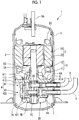
Fig. 1 is a longitudinal sectional view of a rotary compressor according to an embodiment of the present invention. -
Fig. 2 is a view schematically showing an upper muffler shown inFig. 1 . -
Fig. 3 is a partially enlarged view ofFig. 2 . -
Figs. 4A and 4B are views for explaining a Helmholtz resonance. - Hereinafter, an embodiment of the present invention will be described with reference to the accompanying drawings.
- A rotary type compressor 1 shown in
Fig. 1 sucks a gas refrigerant in an accumulator (gas-liquid separator) (not shown) throughpipes compression mechanism 4. - The compressor 1 and the accumulator constitute a refrigerating cycle device such as an air conditioner or a refrigerator and are connected to a refrigerant circuit (not shown) through which the refrigerant circulates.
- The compressor 1 includes a
motor 2 which is a power source, a rotary shaft 3 (crank shaft) which is rotated by a rotational driving force output from themotor 2, the rotarytype compression mechanism 4 which is driven by the rotational driving force transmitted via therotary shaft 3,mufflers rotary shaft 3, and ahousing 5. - The
mufflers compression mechanism 4. - The
housing 5 accommodates themotor 2, therotary shaft 3, thecompression mechanism 4, and themufflers - The
motor 2 includes astator 2A which is fixed to an inner peripheral portion of thehousing 5, and arotor 2B which is disposed inside thestator 2A. Therotor 2B rotates with respect to thestator 2A by supplying power to acoil 2C provided in thestator 2A. - The
rotary shaft 3 includes amain shaft portion 3A which is connected to therotor 2B and protrudes downward from therotor 2B, anupper crank pin 3B which is eccentric to an axis center of themain shaft portion 3A, and alower crank pin 3C which is eccentric to the axis center of themain shaft portion 3A similarly to theupper crank pin 3B. Thelower crank pin 3C is eccentric to the axis center of therotary shaft 3 in a direction which becomes a phase (180°) reverse to theupper crank pin 3B. - The
upper crank pin 3B is disposed in anupper cylinder 412 of thecompression mechanism 4, and thelower crank pin 3C is disposed in alower cylinder 422 of thecompression mechanism 4. - The compression mechanism 4 (
Fig. 1 ) will be described. - The
compression mechanism 4 which is a so-called twin rotary type mechanism includes anupper compression mechanism 41, alower compression mechanism 42, apartition plate 4A, and an upper bearing 6 and alower bearing 7 which rotatably support therotary shaft 3. - The
partition plate 4A partitions an inside of acylinder 412 of theupper compression mechanism 41 and an inside of acylinder 422 of thelower compression mechanism 42. - The
upper compression mechanism 41 is constituted so as to include anupper piston rotor 411 which is provided in theupper crank pin 3B, theupper cylinder 412 in which theupper piston rotor 411 is disposed, and theupper muffler 10 which is disposed around an axis of themain shaft portion 3A. - The
upper piston rotor 411 is fitted to an outer peripheral portion of theupper crank pin 3B and is turned in theupper cylinder 412 according to a rotation of therotary shaft 3. - The refrigerant is sucked into the
upper cylinder 412 through thepipe 8. - The
upper bearing 6 includes anabutment portion 6A which abuts against an upper end surface of theupper cylinder 412 and a cylindrical bearingportion 6B which protrudes upward from theabutment portion 6A and is positioned around the axis of the rotary shaft 3 (main shaft portion 3A). Theabutment portion 6A is fixed to the inner peripheral portion of thehousing 5. - The
upper cylinder 412, theupper muffler 10, thelower cylinder 422, and thelower muffler 20 are integrally assembled to theupper bearing 6 by abolt 113. - The refrigerant sucked into the
upper cylinder 412 is pressed to an outer peripheral portion of the turningupper piston rotor 411 and is compressed in a space in front of a blade (not shown) in a rotation direction. The compressed refrigerant is discharged into theupper muffler 10 through adischarge port 6P (Fig. 2 ) formed in theabutment portion 6A of theupper bearing 6, and is discharged to a space in thehousing 5 below themotor 2 from the inside of theupper muffler 10. - Similarly to the
upper compression mechanism 41, the lower compression mechanism 42 (Fig. 1 ) is constituted so as to include alower piston rotor 421 which is provided in thelower crank pin 3C, thelower cylinder 422 in which thelower piston rotor 421 is disposed, and thelower muffler 20 which is disposed around the axis of themain shaft portion 3A. - The gas refrigerant is sucked into the
lower cylinder 422 through thepipe 9. - The
lower bearing 7 includes anabutment portion 7A which abuts against a lower end surface of thelower cylinder 422 and acylindrical bearing portion 7B which protrudes downward from theabutment portion 7A and is positioned around the axis of the rotary shaft 3 (main shaft portion 3A). - The refrigerant sucked into the
lower cylinder 422 is compressed according to turning of thelower piston rotor 421. The compressed refrigerant is discharged into thelower muffler 20 through a discharge port (not shown) formed in theabutment portion 7A of thelower bearing 7 and into the inner space of thehousing 5, and the compressed refrigerant is discharged to the space below themotor 2 in thehousing 5 through anotch 61A or an opening (not shown) formed in theabutment portion 6A of theupper bearing 6. - As described above, the refrigerant compressed by the
upper compression mechanism 41 and thelower compression mechanism 42 is discharged to the space in thehousing 5 below themotor 2. The refrigerant flows to a space above themotor 2 through a notch provided in thestator 2A or therotor 2B and is discharged to a refrigerant circuit through adischarge pipe 5A provided on an upper portion of thehousing 5. - Each of the
upper compression mechanism 41 and thelower compression mechanism 42 discharges the refrigerant with a pressure variation (pulsation) from the discharge port according to a turning period of each of thepiston rotors mufflers upper compression mechanism 41 and thelower compression mechanism 42 is reduced in themufflers - The compressor 1 of the present embodiment is characterized by a structure of the
upper muffler 10. - First, with reference to
Figs. 2 and3 , a configuration of the upper muffler 10 (hereinafter, referred to as a muffler 10) will be described. - The
muffler 10 includes amuffler body 11 which forms aspace 110 between theabutment portion 6A of the upper bearing 6 and themuffler body 11 and acover 12 which forms acavity 120 between an outerperipheral portion 11S of themuffler body 11 and thecover 12. - For example, each of the
muffler body 11 and thecover 12 is formed of a metal material such as an aluminum alloy by deep drawing. - In the
muffler body 11, the compressed refrigerant which is compressed in the upper cylinder 412 (Fig. 1 ) and ejected from thedischarge port 6P is received in theinner space 110, and the pulsation of the compressed refrigerant is reduced. The inner space of themuffler body 11 is operated as a resistance according to a space volume by the refrigerant ejected into themuffler body 11, and thus, the pulsation of the refrigerant is attenuated by themuffler body 11. - The
muffler body 11 is disposed around the axis of therotary shaft 3. The bearingportion 6B supporting therotary shaft 3 passes through an opening formed at a planar center portion of themuffler body 11. A peripheral edge portion of the opening corresponds to an innerperipheral end 111 of themuffler body 11. - The
muffler body 11 extends from the innerperipheral end 111 toward a radially outer side of therotary shaft 3 by a predetermined diameter and is formed in an approximately cylindrical shape in a plan view. An end portion on a radially outer side of themuffler body 11 is fastened to theupper bearing 6 by thebolts 113 at a plurality of locations in a circumferential direction. - A dimension or a volume of the
muffler body 11 can be appropriately determined so as to conform to an audible frequency component of the pulsation of the compressed refrigerant. This is similarly applied to thecover 12. - The
muffler body 11 includes aportion 11A which extends radially outward from the innerperipheral end 111 positioned above theabutment portion 6A and aportion 11B which extends downward from theportion 11A toward theabutment portion 6A and is disposed on theabutment portion 6A. The refrigerant ejected from thedischarge port 6P is mainly sprayed to theportion 11A. - Shapes of the
portions muffler body 11 is fastened by thebolts 113. Themuffler body 11 is not limited to the shape shown inFig. 2 and can be formed in an appropriate shape. For example, themuffler body 11 can be formed in a dome shape. This is similarly applied to thecover 12. - In the
muffler body 11, adischarge opening 11P and a plurality ofopenings 11H separately from thedischarge opening 11P are formed. - The refrigerant passes through
discharge opening 11P from the inside of themuffler body 11 to the inside of thecavity 120. - The
discharge opening 11P penetrates theportion 11A of themuffler body 11 in a plate thickness direction. In addition, a plurality of discharge openings are formed at intervals in a circumferential direction of themuffler body 11. - A position of the
discharge opening 11P is not particularly limited. However, preferably, thedischarge opening 11P is formed at a position at which a phase angle of thedischarge opening 11P is different from that of thedischarge port 6P, or a position which is away from thedischarge port 6P such that the compressed refrigerant ejected from thedischarge port 6P is not discharged from the inside of themuffler body 11 as it is. As described later, according to this, the refrigerant is introduced into the plurality ofopenings 11H, and thus, a sound absorbing effect can be sufficiently obtained using a Helmholtz resonance. - The number of
discharge openings 11P, an opening area of eachdischarge opening 11P, and a total opening area of the plurality ofdischarge openings 11P are determined in consideration of a balance between a pressure loss for pulsation reduction and the performance of the compressor 1. This is similarly applied to adischarge opening 12P of thecover 12. - In addition, the
discharge opening 11P may be formed in an annular shape along the axis (around an axis of the bearingportion 6B of the upper bearing 6) of therotary shaft 3. - Each of the plurality of
openings 11H penetrates themuffler body 11 in the plate thickness direction. In the example shown inFig. 2 , eachopening 11H is formed in theportion 11A. However, theopening 11H may be formed in theportion 11B or may be formed in both theportions - A cross-sectional area (opening area) of the
opening 11H is much smaller than a cross-sectional area of thedischarge opening 11P. For example, the cross-sectional area of theopening 11H is approximately 1/500 to 1/100 of the cross-sectional area of thedischarge opening 11P. As described later, in order to increase the pulsation reduction effect by theopenings 11H and thecavity 120, preferably, a plurality ofminute openings 11H are formed in themuffler body 11. - As shown in
Fig 4A , eachopening 11H can be formed in a circular round hole. However, theopening 11H is not limited to this, and theopening 11H can be appropriately constituted as long as it causes the inside and the outside of themuffler body 11 to communicate with each other. - In order to increase the pulsation reduction effect, preferably, the plurality of
opening 11H are formed over the entire surface of themuffler body 11. - In the cover 12 (refer to
Figs. 2 and3 ), the refrigerant is received in thecavity 120 between thecover 12 and themuffler body 11 from thespace 110 in themuffler body 11 and is discharged from thedischarge opening 12P. - Similarly to the above-described
muffler body 11, thecover 12 is disposed around the axis of therotary shaft 3, and the bearingportion 6B passes through an opening formed at a planar center portion of thecover 12. An inner peripheral end 121 (peripheral edge portion of the opening) of thecover 12 is slightly erected along the axial direction. An annular gap between the innerperipheral end 121 and the bearingportion 6B becomes thedischarge opening 12P. - Preferably, the
discharge opening 12P is formed at a position away from thedischarge opening 11P such that the refrigerant discharged from thedischarge opening 11P of themuffler body 11 into thecover 12 is not discharged to the outside of thecover 12 as it is. Thedischarge opening 12P may not be formed around the axis of the bearingportion 6B and may be formed so as to penetrate thecover 12 in the plate thickness direction. - The
cover 12 covers the outerperipheral portion 11S of themuffler body 11 and is fastened to theupper bearing 6 together with themuffler body 11 by thebolt 113. - The inner
peripheral end 121 of thecover 12 is positioned at a position which is positioned farther away from theabutment portion 6A of theupper bearing 6 in the axial direction than where the innerperipheral end 111 of themuffler body 11 is positioned. Thecover 12 includes aportion 12A which faces theportion 11A of themuffler body 11 and aportion 12B which extends downward from theportion 12A. - The
cover 12 of the present embodiment covers themuffler body 11 so as to surround the entirety thereof. However, thecover 12 may cover at least a portion of themuffler body 11 as long as thecavity 120 is formed between thecover 12 and themuffler body 11. - According to a height of the
cover 12, the innerperipheral end 121 does not face the bearingportion 6B and may face an outer peripheral portion of therotary shaft 3. In this case, thedischarge opening 12P is formed between the innerperipheral end 121 and the outer peripheral portion of therotary shaft 3. - The lower muffler 20 (
Fig. 1 ) is formed to be approximately similar to theupper muffler 10 and is disposed around an axis of thelower bearing 7 in a direction in which thelower muffler 20 is inverted to theupper muffler 10 in a vertical direction. - Unlike the
upper muffler 10, thelower muffler 20 does not have the cover and is formed of a single member. However, similarly to theupper muffler 10, thelower muffler 20 can be formed to have the muffler body and the cover. - Hereinafter, the pulsation reduction effect by the
upper muffler 10 will be described. - As described above, the
muffler body 11 forms thespace 110 and thecover 12 forms thecavity 120. Accordingly, the refrigerant compressed by thecompression mechanism 41 is ejected to thespace 110 and discharged to thecavity 120 from thedischarge opening 11P, and is discharged to the outside of thecover 12 through thedischarge opening 12P from thecavity 120. In this way, the refrigerant sequentially passes through the inside of themuffler body 11 and the inside of thecover 12, and thus, the pulsation of the refrigerant is reduced. That is, themuffler 10 having themuffler body 11 and thecover 12 functions as a two-stage muffler which reduces the pulsation through two stages. - The
muffler 10 of the present embodiment further reduces the pulsation by establishing the Helmholtz resonance by theopenings 11H of themuffler body 11 and thecavity 120 while maintaining the performance of the pulsation reduction as the two-stage muffler. Theopenings 11H and thecavity 120 constitute a Helmholtz resonator. - As shown in
Fig. 4B , the Helmholtz resonance means that when air masses 15 (air columns) existing inside theopenings 11H passing through thecavity 120 move in directions of hole axes, the air masses resonate at a predetermined frequency with the surrounding air. In this case, thecavity 120 can be regarded as a spring provided in theair masses 15. If theair masses 15 vibrate in a resonance state, frictions between air and the inner peripheral portions of theopenings 11H or frictions between air molecules are remarkably generated, and thus, vibration energy attenuates and a sound pressure decreases (sound is absorbed). - In order to establish the Helmholtz resonance, a cross-sectional area S (horizontal cross-sectional area) of the
opening 11H, a plate thickness L of themuffler body 11, and a volume V of thecavity 120 are determined so as to be a proper relationship to each other. - A basic expression of the Helmholtz resonance is as follows. Here, f is a natural frequency of the
air mass 15 and C is a speed of sound.
[Expression 1]
- Sound absorption by the Helmholtz resonance is assumed to be LS << V. That is, LS which is an inner volume of the
opening 11H is very small so as to be negligible compared to the volume V of thecavity 120. For example, depending on the frequency f for reducing the pulsation, a hole diameter of theopening 11H is approximately 0.15 mm, and the plate thickness L is approximately 1.5 mm. Since eachopening 11H is minute, the total LS of the plurality ofopenings 11H is also very small as compared with the volume V of thecavity 120. - As described above, since the cross-sectional area of the
opening 11H is minute compared to thedischarge opening 11P or thedischarge opening 12P, theopenings 11 do not affect a subject (mainstream) of a flow of the refrigerant involved in a basic pulsation reduction mechanism of themuffler 10 in which the refrigerant received in the expandingspace 110 is discharged from thenarrow discharge opening 11P and is received in thecavity 120 to be discharged to thedischarge opening 12P. - The cross-sectional area S or the plate thickness L can be determined in consideration of an appropriate frequency f to be reduced.
- For example, when the natural frequency (resonance frequency) of
air mass 15 is 250 Hz, the hole diameter of theopening 11H can be set to 0.15 mm, the plate thickness of themuffler body 11 to 1.5 mm, and the volume V of thecavity 120 to 200 mm3. - Here, in order to obtain a pulsation reduction effect (sound absorbing effect), it is necessary that the hole diameter of the
opening 11 H is sufficiently small, and an upper limit of a sum of the cross-sectional areas S of the plurality ofopenings 11H is 1% of the surface area of themuffler body 11. - Since the
air mass 15 in theopening 11H moves so as to draw the surrounding air, it is necessary to correct the length (plate thickness L) of theair mass 15 according to the shape around theopening 11H (opening portion correction). For example, if a radius of theopening 11H is defined as a, L' obtained from L + 1.7a = L' can be applied to the Expression (1). - According to the compressor 1 of the present embodiment, the pulsation of the refrigerant compressed by the
upper compression mechanism 41 and thelower compression mechanism 42 can be sufficiently reduced by themufflers muffler 10, the pulsation reduction effect based on the Helmholtz resonance can be obtained while the pulsation reduction effect of the two-stage muffler which repeats the discharge of pulsation into the space is maintained. The movement of theair mass 15 inside theminute opening 11H does not affect the mainstream inside the muffler. - Therefore, according to the present embodiment, the pulsation of the refrigerant is sufficiently reduced while the performance of the compressor 1 is secured, and thus, it is possible to suppress a noise caused by the pressure variation of the refrigerant.
- In the
muffler 10, themuffler 10 itself becomes a sound source by the pulsation reduction and can suppress radiation of the sound pressure, and thus, even if the plate thickness of themuffler body 11 or thecover 12 is thin, it is possible to suppress the noise. - In addition, as long as the gist of the present invention is not deviated, it is possible to select configurations described in the embodiment or to appropriately change the configurations to other configurations.
- The compression mechanism mounted on the compressor of the present invention is not limited to the twin rotary
type compression mechanism 4. That is, the compression mechanism may be a single rotary type compression mechanism having a pair of cylinder and piston rotor and a muffler. - The compressor of the present invention is not limited to the rotary compressor and may be a scroll compressor. In this case, the configuration of the present invention may be applied to the muffler (also referred to as a discharge cover) which receives the compressed refrigerant discharged from the scroll type compression mechanism. That is, the discharge cover (muffler) includes a muffler body and a cover, and the
minute opening 11H may be formed in the muffler body. - As the power source of the compressor of the present invention, in addition to the motor, for example, an engine or the like may be used.
-
- 1:
- compressor
- 2:
- motor
- 2A:
- stator
- 2B:
- rotor
- 2C:
- coil
- 3:
- rotary shaft
- 3A:
- main shaft portion
- 3B:
- upper crank pin
- 3C:
- lower crank pin
- 4:
- compression mechanism
- 4A:
- partition plate
- 5:
- housing
- 5A:
- discharge pipe
- 6:
- upper bearing
- 6A:
- abutment portion
- 6B:
- bearing portion
- 6P:
- discharge port
- 7:
- lower bearing
- 7A:
- abutment portion
- 7B:
- bearing portion
- 8, 9:
- pipe
- 10:
- upper muffler
- 11:
- muffler body
- 11A:
- portion
- 11B:
- portion
- 11P:
- discharge opening
- 11H:
- opening
- 11S:
- outer peripheral portion
- 12:
- cover
- 12A:
- portion
- 12B:
- portion
- 12P:
- discharge opening
- 15:
- air mass
- 20:
- lower muffler
- 41:
- upper compression mechanism
- 42:
- lower compression mechanism
- 61A:
- notch
- 110:
- space
- 111:
- inner peripheral end
- 113:
- bolt
- 120:
- cavity
- 121:
- inner peripheral end
- 411:
- upper piston rotor
- 412:
- upper cylinder
- 421:
- lower piston rotor
- 422:
- lower cylinder
- L:
- plate thickness
- S:
- cross-sectional area
- V:
- volume
Claims (2)
- A compressor comprising:a compression mechanism which compresses a fluid; anda muffler which reduces a pulsation of the fluid compressed by the compression mechanism,wherein the muffler includesa muffler body which receives the fluid from the compression mechanism into an inside of the muffler body, anda cover which forms a cavity between an outer peripheral portion of the muffler body and the cover and discharges the fluid received from the inside of the muffler body,wherein the muffler body includes a plurality of openings which are formed to penetrate the muffler body in a plate thickness direction, separately from a discharge opening through which the fluid passes from the inside of the muffler body into the cavity, andwherein sound is absorbed by establishing a Helmholtz resonance with respect to an air mass existing inside each opening communicating with the cavity from a relationship between a speed of sound C, a cross-sectional area S of each of the openings, a plate thickness L, and a volume V of the cavity.
- The compressor according to claim 1,
wherein the compression mechanism includes a piston rotor which is provided in a rotary shaft and a cylinder in which the piston rotor is disposed, and
wherein the muffler body and the cover are disposed around an axis of the rotary shaft.
Applications Claiming Priority (2)
| Application Number | Priority Date | Filing Date | Title |
|---|---|---|---|
| JP2016164355A JP2018031303A (en) | 2016-08-25 | 2016-08-25 | Compressor |
| PCT/JP2017/028710 WO2018037906A1 (en) | 2016-08-25 | 2017-08-08 | Compressor |
Publications (2)
| Publication Number | Publication Date |
|---|---|
| EP3447296A1 true EP3447296A1 (en) | 2019-02-27 |
| EP3447296A4 EP3447296A4 (en) | 2019-03-06 |
Family
ID=61245666
Family Applications (1)
| Application Number | Title | Priority Date | Filing Date |
|---|---|---|---|
| EP17843391.8A Withdrawn EP3447296A4 (en) | 2016-08-25 | 2017-08-08 | Compressor |
Country Status (3)
| Country | Link |
|---|---|
| EP (1) | EP3447296A4 (en) |
| JP (1) | JP2018031303A (en) |
| WO (1) | WO2018037906A1 (en) |
Cited By (4)
| Publication number | Priority date | Publication date | Assignee | Title |
|---|---|---|---|---|
| CN110630471A (en) * | 2018-06-25 | 2019-12-31 | 上海海立电器有限公司 | A device for reducing compressor noise |
| CN110685887A (en) * | 2019-10-15 | 2020-01-14 | 珠海凌达压缩机有限公司 | Muffler and compressor containing the same |
| WO2023187438A1 (en) * | 2022-03-28 | 2023-10-05 | Siam Compressor Industry Co., Ltd. | A scroll compressor |
| US12049897B2 (en) * | 2019-09-24 | 2024-07-30 | Guangdong Meizhi Compressor Co., Ltd. | Baffle plate for compressor, compressor, and refrigeration apparatus |
Families Citing this family (7)
| Publication number | Priority date | Publication date | Assignee | Title |
|---|---|---|---|---|
| CN110630472B (en) * | 2018-06-25 | 2021-09-10 | 上海海立电器有限公司 | Device for reducing noise of compressor |
| KR102083966B1 (en) * | 2018-09-05 | 2020-03-03 | 엘지전자 주식회사 | A compressor |
| CN113513474B (en) | 2020-04-09 | 2023-02-21 | 江森自控空调冷冻设备(无锡)有限公司 | Screw compressor, refrigeration system and control method of refrigeration system |
| CN112392691B (en) * | 2020-12-03 | 2024-10-11 | 珠海格力电器股份有限公司 | Exhaust assembly, compressor and air conditioner |
| CN112610496A (en) * | 2020-12-31 | 2021-04-06 | 珠海格力电器股份有限公司 | Compressor silencer and compressor with same |
| CN113007097B (en) * | 2021-03-25 | 2023-05-12 | 珠海格力节能环保制冷技术研究中心有限公司 | Flange structure, compressor and air conditioner |
| CN117365907A (en) * | 2023-11-23 | 2024-01-09 | 珠海格力电器股份有限公司 | Porous pipe muffler and fluid machinery equipment for gaseous medium |
Family Cites Families (6)
| Publication number | Priority date | Publication date | Assignee | Title |
|---|---|---|---|---|
| JPH04159490A (en) * | 1990-10-22 | 1992-06-02 | Daikin Ind Ltd | Rotary compressor |
| JPH08151918A (en) * | 1994-11-29 | 1996-06-11 | Osaka Yakin Kogyo Kk | Muffler |
| JPH11210660A (en) * | 1998-01-29 | 1999-08-03 | Mitsubishi Electric Corp | Scroll compressor |
| KR100575829B1 (en) * | 2003-12-31 | 2006-05-03 | 엘지전자 주식회사 | Suction Muffler Assembly Structure of Reciprocating Compressor |
| JP2012072679A (en) * | 2010-09-28 | 2012-04-12 | Daikin Industries Ltd | Compressor |
| CN104379937B (en) * | 2012-05-09 | 2017-12-22 | 三菱电机株式会社 | Hermetic Compressor and Heat Pump Units |
-
2016
- 2016-08-25 JP JP2016164355A patent/JP2018031303A/en active Pending
-
2017
- 2017-08-08 EP EP17843391.8A patent/EP3447296A4/en not_active Withdrawn
- 2017-08-08 WO PCT/JP2017/028710 patent/WO2018037906A1/en not_active Ceased
Cited By (6)
| Publication number | Priority date | Publication date | Assignee | Title |
|---|---|---|---|---|
| CN110630471A (en) * | 2018-06-25 | 2019-12-31 | 上海海立电器有限公司 | A device for reducing compressor noise |
| CN110630471B (en) * | 2018-06-25 | 2021-09-10 | 上海海立电器有限公司 | Device for reducing noise of compressor |
| US12049897B2 (en) * | 2019-09-24 | 2024-07-30 | Guangdong Meizhi Compressor Co., Ltd. | Baffle plate for compressor, compressor, and refrigeration apparatus |
| CN110685887A (en) * | 2019-10-15 | 2020-01-14 | 珠海凌达压缩机有限公司 | Muffler and compressor containing the same |
| CN110685887B (en) * | 2019-10-15 | 2025-10-17 | 珠海凌达压缩机有限公司 | Muffler and compressor comprising same |
| WO2023187438A1 (en) * | 2022-03-28 | 2023-10-05 | Siam Compressor Industry Co., Ltd. | A scroll compressor |
Also Published As
| Publication number | Publication date |
|---|---|
| EP3447296A4 (en) | 2019-03-06 |
| JP2018031303A (en) | 2018-03-01 |
| WO2018037906A1 (en) | 2018-03-01 |
Similar Documents
| Publication | Publication Date | Title |
|---|---|---|
| WO2018037906A1 (en) | Compressor | |
| CN105683576B (en) | Electric scroll compressor | |
| CN105556125B (en) | Electric scroll compressor | |
| CN108626125B (en) | Rotary compressor | |
| EP3364130B1 (en) | Accumulator having multiple pipes, and compressor | |
| US20150192126A1 (en) | Electric compressor | |
| KR20130055407A (en) | Rotary compressor and manufacturing method thereof | |
| JP2013177826A (en) | Electric compressor | |
| EP2905470B1 (en) | Rotary compressor | |
| EP3168475A1 (en) | Attachment structure, and electric compressor | |
| EP3369932B1 (en) | Rotary compressor | |
| US6176688B1 (en) | Discharge muffler arrangement | |
| EP2129912B1 (en) | Mount for compressor shell | |
| EP3015710B1 (en) | Compressor | |
| KR101718037B1 (en) | Enclosed compressor | |
| EP2894341B1 (en) | Compressor | |
| KR100480126B1 (en) | Hermetic rotary compressor with resonator | |
| JP7325646B2 (en) | Compressor support structure | |
| JP2013177827A (en) | Electric compressor | |
| JP4593425B2 (en) | Gas compressor | |
| JP2011179374A (en) | Scroll compressor | |
| JPH03107594A (en) | Silencer of compressor | |
| KR101990137B1 (en) | Accumulator and Compression Unit including the same | |
| EP2918841A1 (en) | Scroll compressor | |
| KR100533045B1 (en) | Scroll compressor with function of noise attenuation |
Legal Events
| Date | Code | Title | Description |
|---|---|---|---|
| STAA | Information on the status of an ep patent application or granted ep patent |
Free format text: STATUS: THE INTERNATIONAL PUBLICATION HAS BEEN MADE |
|
| PUAI | Public reference made under article 153(3) epc to a published international application that has entered the european phase |
Free format text: ORIGINAL CODE: 0009012 |
|
| STAA | Information on the status of an ep patent application or granted ep patent |
Free format text: STATUS: REQUEST FOR EXAMINATION WAS MADE |
|
| 17P | Request for examination filed |
Effective date: 20181120 |
|
| AK | Designated contracting states |
Kind code of ref document: A1 Designated state(s): AL AT BE BG CH CY CZ DE DK EE ES FI FR GB GR HR HU IE IS IT LI LT LU LV MC MK MT NL NO PL PT RO RS SE SI SK SM TR |
|
| AX | Request for extension of the european patent |
Extension state: BA ME |
|
| A4 | Supplementary search report drawn up and despatched |
Effective date: 20190131 |
|
| RIC1 | Information provided on ipc code assigned before grant |
Ipc: F04C 23/00 20060101ALI20190125BHEP Ipc: F04B 39/00 20060101ALI20190125BHEP Ipc: F04C 29/06 20060101AFI20190125BHEP |
|
| GRAP | Despatch of communication of intention to grant a patent |
Free format text: ORIGINAL CODE: EPIDOSNIGR1 |
|
| STAA | Information on the status of an ep patent application or granted ep patent |
Free format text: STATUS: GRANT OF PATENT IS INTENDED |
|
| STAA | Information on the status of an ep patent application or granted ep patent |
Free format text: STATUS: THE APPLICATION HAS BEEN WITHDRAWN |
|
| DAV | Request for validation of the european patent (deleted) | ||
| DAX | Request for extension of the european patent (deleted) | ||
| INTG | Intention to grant announced |
Effective date: 20191022 |
|
| 18W | Application withdrawn |
Effective date: 20191017 |