EP3447271A1 - Heating system for convergent-divergent secondary nozzle - Google Patents
Heating system for convergent-divergent secondary nozzle Download PDFInfo
- Publication number
- EP3447271A1 EP3447271A1 EP18190107.5A EP18190107A EP3447271A1 EP 3447271 A1 EP3447271 A1 EP 3447271A1 EP 18190107 A EP18190107 A EP 18190107A EP 3447271 A1 EP3447271 A1 EP 3447271A1
- Authority
- EP
- European Patent Office
- Prior art keywords
- neck
- nozzle
- vein
- assembly according
- heating
- Prior art date
- Legal status (The legal status is an assumption and is not a legal conclusion. Google has not performed a legal analysis and makes no representation as to the accuracy of the status listed.)
- Granted
Links
- 238000010438 heat treatment Methods 0.000 title claims abstract description 82
- 210000003462 vein Anatomy 0.000 claims abstract description 66
- 238000011144 upstream manufacturing Methods 0.000 claims abstract description 29
- 239000000203 mixture Substances 0.000 claims abstract description 7
- 238000009792 diffusion process Methods 0.000 claims description 18
- 230000009977 dual effect Effects 0.000 claims 1
- 125000006850 spacer group Chemical group 0.000 claims 1
- 238000005070 sampling Methods 0.000 description 7
- 230000004907 flux Effects 0.000 description 6
- 230000000737 periodic effect Effects 0.000 description 6
- 230000000694 effects Effects 0.000 description 4
- 241000861223 Issus Species 0.000 description 3
- 230000006835 compression Effects 0.000 description 3
- 238000007906 compression Methods 0.000 description 3
- 230000007423 decrease Effects 0.000 description 3
- 239000000243 solution Substances 0.000 description 3
- 208000031968 Cadaver Diseases 0.000 description 2
- 238000002485 combustion reaction Methods 0.000 description 2
- 238000002347 injection Methods 0.000 description 2
- 239000007924 injection Substances 0.000 description 2
- 238000009434 installation Methods 0.000 description 2
- DCWUQHLHCBQOAM-PIXDULNESA-N 4-amino-5-[(e)-2-chloroethenyl]-1-[(2r,4s,5r)-4-hydroxy-5-(hydroxymethyl)oxolan-2-yl]pyrimidin-2-one Chemical compound C1=C(\C=C\Cl)C(N)=NC(=O)N1[C@@H]1O[C@H](CO)[C@@H](O)C1 DCWUQHLHCBQOAM-PIXDULNESA-N 0.000 description 1
- 230000000712 assembly Effects 0.000 description 1
- 238000000429 assembly Methods 0.000 description 1
- 230000009286 beneficial effect Effects 0.000 description 1
- 230000000903 blocking effect Effects 0.000 description 1
- 230000001186 cumulative effect Effects 0.000 description 1
- 230000009849 deactivation Effects 0.000 description 1
- 230000005611 electricity Effects 0.000 description 1
- 238000005516 engineering process Methods 0.000 description 1
- 230000010354 integration Effects 0.000 description 1
- 230000003993 interaction Effects 0.000 description 1
- 239000000463 material Substances 0.000 description 1
- 230000003071 parasitic effect Effects 0.000 description 1
- 230000000149 penetrating effect Effects 0.000 description 1
- 230000035515 penetration Effects 0.000 description 1
- 230000000750 progressive effect Effects 0.000 description 1
- 230000009467 reduction Effects 0.000 description 1
- 238000007789 sealing Methods 0.000 description 1
- 238000004513 sizing Methods 0.000 description 1
- 238000001228 spectrum Methods 0.000 description 1
- 238000010792 warming Methods 0.000 description 1
Images


Classifications
-
- F—MECHANICAL ENGINEERING; LIGHTING; HEATING; WEAPONS; BLASTING
- F02—COMBUSTION ENGINES; HOT-GAS OR COMBUSTION-PRODUCT ENGINE PLANTS
- F02K—JET-PROPULSION PLANTS
- F02K1/00—Plants characterised by the form or arrangement of the jet pipe or nozzle; Jet pipes or nozzles peculiar thereto
- F02K1/28—Plants characterised by the form or arrangement of the jet pipe or nozzle; Jet pipes or nozzles peculiar thereto using fluid jets to influence the jet flow
- F02K1/34—Plants characterised by the form or arrangement of the jet pipe or nozzle; Jet pipes or nozzles peculiar thereto using fluid jets to influence the jet flow for attenuating noise
-
- F—MECHANICAL ENGINEERING; LIGHTING; HEATING; WEAPONS; BLASTING
- F01—MACHINES OR ENGINES IN GENERAL; ENGINE PLANTS IN GENERAL; STEAM ENGINES
- F01D—NON-POSITIVE DISPLACEMENT MACHINES OR ENGINES, e.g. STEAM TURBINES
- F01D9/00—Stators
- F01D9/02—Nozzles; Nozzle boxes; Stator blades; Guide conduits, e.g. individual nozzles
-
- F—MECHANICAL ENGINEERING; LIGHTING; HEATING; WEAPONS; BLASTING
- F01—MACHINES OR ENGINES IN GENERAL; ENGINE PLANTS IN GENERAL; STEAM ENGINES
- F01D—NON-POSITIVE DISPLACEMENT MACHINES OR ENGINES, e.g. STEAM TURBINES
- F01D25/00—Component parts, details, or accessories, not provided for in, or of interest apart from, other groups
- F01D25/08—Cooling; Heating; Heat-insulation
- F01D25/10—Heating, e.g. warming-up before starting
-
- F—MECHANICAL ENGINEERING; LIGHTING; HEATING; WEAPONS; BLASTING
- F02—COMBUSTION ENGINES; HOT-GAS OR COMBUSTION-PRODUCT ENGINE PLANTS
- F02K—JET-PROPULSION PLANTS
- F02K1/00—Plants characterised by the form or arrangement of the jet pipe or nozzle; Jet pipes or nozzles peculiar thereto
- F02K1/38—Introducing air inside the jet
- F02K1/386—Introducing air inside the jet mixing devices in the jet pipe, e.g. for mixing primary and secondary flow
-
- F—MECHANICAL ENGINEERING; LIGHTING; HEATING; WEAPONS; BLASTING
- F02—COMBUSTION ENGINES; HOT-GAS OR COMBUSTION-PRODUCT ENGINE PLANTS
- F02K—JET-PROPULSION PLANTS
- F02K1/00—Plants characterised by the form or arrangement of the jet pipe or nozzle; Jet pipes or nozzles peculiar thereto
- F02K1/46—Nozzles having means for adding air to the jet or for augmenting the mixing region between the jet and the ambient air, e.g. for silencing
-
- F—MECHANICAL ENGINEERING; LIGHTING; HEATING; WEAPONS; BLASTING
- F02—COMBUSTION ENGINES; HOT-GAS OR COMBUSTION-PRODUCT ENGINE PLANTS
- F02K—JET-PROPULSION PLANTS
- F02K1/00—Plants characterised by the form or arrangement of the jet pipe or nozzle; Jet pipes or nozzles peculiar thereto
- F02K1/78—Other construction of jet pipes
- F02K1/82—Jet pipe walls, e.g. liners
- F02K1/827—Sound absorbing structures or liners
Definitions
- the present invention relates to the field of noise reduction for a mixed flow turbomachine. It relates more particularly to the rear body of a turbofan engine, where the primary flow leaving the engine and the secondary flow are mixed inside a secondary nozzle, to form a jet propelled into the external air.
- turbomachines concerned is thus related to the LDMF (" long-duct mixed-flow ”) nozzles, that is to say a secondary nozzle extending beyond the mixing of flows.
- LDMF long-duct mixed-flow
- the invention relates in particular to solutions to acoustics problems in the context of secondary convergent-divergent nozzle.
- a source of noise comes from the fact that a Mach pocket is present at the neck of the nozzle.
- the interaction between the turbulence resulting from the mixing of the two streams and the supersonic flow zones in the nozzle is a source of high frequency noise. This phenomenon can occur especially when the nozzle begins to prime.
- the present invention is in the context of so-called convergent-divergent nozzles.
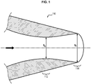
- the latter make it possible to improve the performance of the mixed flow nozzles, in particular by increasing the size of the convergent-divergent (ratio called "CVDC" and classically referenced A9 / A8 - see figure 1 , where there is illustrated a nozzle 110, a trailing edge 114 and a neck 112 and the respective sections S f / S c ).
- a convergent-divergent nozzle by definition, has a minimum section whose axial positioning does not coincide with one of the ends of the duct.
- a convergent-divergent secondary nozzle has two advantages: it makes it possible to substantially modify the coefficient of flow with a low expansion ratio and to improve the performance of the nozzle. This increase is beneficial for the performance of the engine but it is damaging acoustically.
- the invention aims to reduce the above-mentioned acoustic consequences in the context of secondary convergent-divergent nozzle.
- the invention is in several main embodiments.
- the turbomachine rear body 100 concerned belongs to a turbomachine 10 with a double flow, comprising a primary vein Vp and a secondary vein Vs.
- a turbomachine 10 with a double flow comprising a primary vein Vp and a secondary vein Vs.
- In the primary vein Vp thus circulates the primary flow and in the secondary vein Vs thus circulates the secondary flow.
- the turbomachine 10 is arranged around a longitudinal axis X.
- the abscissa is defined as the position along this longitudinal axis X.
- the turbomachine 10 comprises conventional elements known to those skilled in the art, such as one or more compression stages, a combustion chamber and finally one or more stages of turbines, which involve in particular the compressors and also a fan, which feeds the secondary vein Vs and provides the bulk of the thrust.
- the primary vein Vp is defined by a primary nozzle 11, which allows the ejection of the primary flow.
- the primary nozzle 11 may be formed of several different parts.
- the turbomachine 10 incorporates conventional elements known to those skilled in the art.
- the downstream end, the secondary vein is defined by a nozzle 110, said secondary nozzle.
- the secondary nozzle 110 ejects the secondary flow, mixed with the primary flow.
- This secondary nozzle 110 is convergent-divergent. As indicated in the introduction, this means that the radius (or diameter) of the nozzle decreases and then rises again, in the flow direction of the flow. The direct consequence is that the flow section decreases and then increases again. Called "neck" 112 of the secondary nozzle portion of the nozzle 110, at an abscissa x pass, where this section is minimal.
- the convergence-divergence ratio is typically between 100% and 105% (ratio of the section at the trailing edge 114 on the section at the neck 112: S f / S c ).
- the nozzle 110 is generally formed of an inner wall 110a and an outer cover 110b, which define a volume 111 between them.
- the turbomachine rear body 100 may further comprise a central body 12 limiting the radial extension of the primary stream inside the nozzle 110.
- This central body 12 is not concerned by the invention. It is located on the longitudinal axis X and usually stops after a trailing edge 120 of the nozzle.
- the primary nozzle 11 thus includes a trailing edge 120, at an abscissa x p upstream of the abscissa x col.
- This trailing edge 120 may have, in a section orthogonal to the axis X, a circular shape.
- the primary nozzle 11 may end with a lobed mixer 130 which has the function, as indicated in the introduction, of mixing the primary and secondary flows before they are completely ejected from the secondary nozzle 110.
- the lobed mixer 130 is a profiled piece extending inside the secondary nozzle 110, the walls defining inside the primary vein Vp and outside the secondary vein Vs.
- the mixers may have symmetrical lobes and periodic, or non-symmetrical and / or non-periodic.
- the thickness of the trailing edge 120 of the mixer 130 is generally small in order to avoid a base effect between the two flows.
- the lobe mixer 130 generally stops at a significant distance from the downstream end of the secondary nozzle 110 to allow the flow mixture to homogenize. It is recalled that the invention is placed in the framework of turbomachines LDMF (" long duct - mixed flow ").
- an exemplary embodiment of the mixer 130 is constituted by symmetrical lobes, periodic in azimuth about the longitudinal axis X.
- the trailing edge line 120 has a three-dimensional shape corrugated in azimuth and regular passing periodically by a low point 132 of minimum radius and a high point 134 of maximum radius.
- the shape of the mixer is preferably obtained by joining this trailing edge line 120 by smooth smooth surfaces, on one side to the circular section of the outer wall of the primary nozzle 11, on the other side to the circular section of the inner wall of secondary vein Vs.
- Known means allow the skilled person to obtain these smooth surfaces by defining regular laws of radius variation for joining the inlet sections to the trailing edge 120 of the lobe mixer 130.
- the evolutions of the trailing edge 120 of the mixer 130 are periodic.
- the average surface between the radially outer wall and the radially inner wall of the mixer 130 makes periodic undulations in azimuth about the longitudinal axis X which create, on the side of the primary flow under the high points 134 of the trailing edge 120, diverging lobes (so-called hot lobes and referenced 134 for simplification), and create, on the side of the secondary flow above the low points 132 of the trailing edge 120, convergent lobes (called cold lobes and referenced 132 for simplification) .
- the abscissa x p on the longitudinal axis X which determines the maximum extension of the downstream lobe mixer corresponds to the high points of the hot lobes.
- the abscissa x p passes an ejection plane, that is to say a plane from which the flow of air is ejected from the hot lobes.
- the trailing edge will be considered to be the high point of the hot lobes.
- the plane comprising the trailing edge of a primary nozzle without a mixer is identical to the ejection plane of the mixer.
- This embodiment of the mixer comprises eighteen hot lobes symmetrical about the axial plane passing through their middle and distributed periodically.
- a lobe mixer 130 by modifying its axial extension, the penetration rate of the lobes (determined essentially by the rays of the high points 134 and 132 of the trailing edge). 120), the shape of this trailing edge 120, as well as the number of lobes.
- the lobes may also have no axial planes of symmetry.
- this periodicity can be locally affected by changing the shape of some lobes, for example to adapt the mixer 130 to a pylon passage.
- the lobe mixer 130 promotes the mixing of the primary Vp and secondary Vs flows in the vein inside the secondary nozzle 110, in particular by causing shears and vortices at the interface between the streams.
- the secondary nozzle 110 includes a heating system with a heating element.
- the heating element is located on at least a portion of the inner circumference of the secondary nozzle, in a longitudinal position at the neck 112, or upstream of the neck 112 (or both).
- the heating system makes it possible to heat the air locally and to reduce the noise.
- the heating system comprises a heating radiator system (and the heating element is a heating plate) and in the second embodiment , the heating system comprises a hot air diffusion system (and the heating element is an air diffuser).
- the secondary nozzle 110 comprises a heating radiator system 140 which serves to heat the flow passing through the nozzle 110, and more specifically the flow of air which passes through the Mach pocket or pockets located at the neck 112, close to the wall. internal of the nozzle 110. It is therefore an active system.
- the heating radiator system 140 comprises one or more heating plates 142 positioned on at least a portion of the inner circumference of the secondary nozzle 110, ie all around the circumference ( figures 3 and 4 ), or partially ( figures 5 and 6 for example).
- the term plate refers to an element, which, when laid flat, has a small thickness compared to its other main dimensions.
- These plates 142 allow optimal integration of the heating radiator system 140 on the inner wall of the secondary nozzle 110 without disturbing the flow of the air flow.
- the hotplate (s) 142 are located at the neck 112, or upstream of the neck 112, ie between said neck 112 and the trailing edge 120 of the primary nozzle 11.
- the goal is that the wake penetrating the Mach pocket is warmed, so as to limit the acoustic effects. For this reason, since the Mach pocket is just downstream of the neck 112, it is not useful for the plates 142 to extend much further downstream of the neck 112. A longitudinal extension downstream of the neck length less than 0, neck 2xD, wherein D is the neck diameter of the nozzle 110 at x collar, is preferable.
- the hotplate (s) 142 may be positioned upstream of the neck 112. In this configuration, preference is given to one or more heating plates 220 which do not extend longitudinally further upstream than 2xD neck from the neck 112.
- heating upstream of the neck 112 makes it possible to heat the stream for the Mach pocket.
- the heating plate (s) 142 can thus extend longitudinally, from the neck 112, up to 2xD neck upstream.
- the hotplates 142 can be made in many ways.
- a preferential mode consists in providing them with electrical resistances that generate heat when an electric current passes through them.
- the plates can then make the grid shape consist of heating filaments.
- the heating plates 142 therefore consist of an electric heater.
- the supply of electricity is for example from a generator driven by an accessory gearbox ("AGB" for " accessory gearbox ”) which takes power on a shaft of the turbomachine. Batteries may be provided for supplying the heating plates 142 in the absence of availability of the generator.
- a particular embodiment of the heating radiator system 140 is related to the presence of the lobe mixer 130.
- the lobe mixer 130 which has hot lobes 134 and cold lobes 132, causes different wakes that do not follow the same path. In this case, it is mainly the area between the wakes from the hot lobes 134 and the secondary nozzle 110 which need to be heated by the heating radiator system 140.
- the latter may comprise a plurality of heating segments 144a, 144b, arranged at a distance from each other on different portions of the circumference of the nozzle 110 (see figures 5 and 6 ).
- Each heating segment 144a, 144b is located opposite a hot lobe 134.
- the heating segments 144a, 144b and hot lobes 134 are at the same azimuths.
- the width of the segment 144a, 144b may be equal to a radial projection of the lobe on the inner circumference of the secondary nozzle 110 (that is to say by orthogonal projection from a point of the longitudinal axis X), or equal the width of the lobe or any dimension of the same order of magnitude (provided that the segments are sufficiently narrow to ensure that they are spaced from each other, see figure 6 ). In any case, symmetrical connections are preferred, that is to say that the top of the hot lobe 134 is radially aligned with the center of the heating segment 144a, 144b corresponding.
- heating segments 144a, 144b are thus preferably as many heating segments 144a, 144b as hot lobes 132.
- Each segment may be composed of one or more plates 142, depending on the size of the plates and segments 144a, 144b.
- This configuration avoids using energy to heat the area opposite the cold lobes whose wake does not impact the mach pocket.
- the heating plates 142, or the plurality of heating plates 142 may have a temperature gradient to prevent heating of the material on which they are placed.
- the gradient consists of having a higher temperature in the center than at the periphery.
- An increase in the temperature locally of 50 ° K allows for example to lower the Mach between 0.90 and 0.95, compared to a Mach of 1 for a temperature of 320 ° K.
- the turbomachine rear body 10 comprises a hot air diffusion system 200 in the secondary nozzle 110 which serves to heat the flow passing through the secondary nozzle 110, and more specifically the flow of air which passes through the Mach pocket or pockets. located at the neck 112, near the inner wall of the nozzle 110.
- This system 200 comprises several elements.
- a sample 210 is provided in the primary vein Vp, in order to take a fraction of the primary flow.
- the primary flow is hot.
- a diffuser 220 is provided on at least a portion of an inner circumference of the nozzle 110. Longitudinally, the diffuser is located at the neck 112, or upstream of the neck 112, that is between said neck 112 and the trailing edge 120 of the primary vein Vp (that is to say the ejection plane of the mixer 130 when there is one).
- a pipe 230 makes it possible to fluidly connect the sample 210 in the primary vein Vp to the diffuser 220 of the nozzle 110. The pipe 230 passes through the secondary vein Vs.
- This diffusion system 220 has the sole function of heating the air, not to disturb the flow, as the so-called solutions “micro-jets” propose (see FR3016411 or FR2975135 ). It is not therefore an "injection” system, which implies that the flow injected deliberately disturbs the flow, but “diffusion”.
- a plurality of sampling 220 may be provided, distributed over a circumference of the primary vein Vp. This makes it possible to better distribute the sampling and the diffusion in the diffuser 220. In the same way, a plurality of pipe 230 is provided.
- the pipe 230 passes through a structural arm 13.
- the pipe then extends into the volume 111 between the inner wall 110a and the outer cover 110b of the nozzle 110.
- a plurality of pipes 130 can pass through a plurality of structural trees 13, either in equal number or in lower number, by grouping the flow of several samples within the same pipe 130 if it is desired to provide more samples 210 that there are structural trees 13.
- the diffuser 220 is integrated in the nozzle 110 so that its physical presence does not disturb the flow of the air flow.
- Closing means are provided to block the sampling, so that it is an active system. Indeed, it is better to be able to deactivate this system during cruising phases.
- the sealing means are preferably arranged at the sampling 210, in order to close the entrance of the conduit 230 so as not to generate deadlock phenomena.
- the diffuser may extend over the entire internal circumference of the nozzle, however, it may extend only over portions of the inner circumference, in specific areas (see below). Longitudinally, it extends over a certain distance. The goal is that the contact area between the wakes of the hot lobes of the mixer and the pockets of mach is warmed, so as to limit the acoustic effects. For this reason, as the Mach pocket is located at the neck 112, it is not useful for the diffusers 220 to extend much downstream of the neck 112. A longitudinal extension downstream of the neck length less than 0.2xD col, where D is the neck diameter of the nozzle 110 at x collar, is preferable.
- the diffusers 220 can thus extend longitudinally, from the neck 112 up to 1xD neck upstream or less.
- the diffuser 220 may be positioned upstream of the neck 112.
- a diffuser 220 is preferred that does not extend longitudinally further upstream than 1xD- neck from the neck 112.
- a diffuser is implemented. which diffuses on the neck and upstream of the neck, up to 1xD collar upstream of the collar 112.
- the diffuser 220 has the function of heating the air by injecting warmer air without disturbing the flow. Indeed, the diffuser 220 does not work as a nozzle.
- the diffuser 220 comprises a grid 221, consisting of a plurality of orifices (see FIG. figure 9 ). This plurality of orifices makes it possible to distribute the diffusion of air and to diffuse it into the vein of the nozzle 110.
- the diffusion system 200 may comprise means for slowing the flow of air, such as internal grids, baffles or others, for example arranged at inside the pipe 230.
- the withdrawal of air 210 in the primary stream Vp must be as low as possible. It is determined according to its longitudinal position, the surface of the diffuser 220 and the desired temperature rise at the Mach pocket (at a fixed external temperature).
- the withdrawal of air 210 may be carried out at various longitudinal locations of the turbomachine.
- the sample 210 is upstream of the trailing edge of the primary vein Vp.
- the sample 210 is upstream of the mixer, ie upstream of the beginning of the hot and cold lobes.
- the longitudinal distance between the trailing edge of the primary vein Vp (i.e., the ejection plane when there is a mixer 130) and the sampling is greater than the longitudinal distance between the trailing edge. leakage of the primary vein Vp (or the ejection plane) and the neck 112.
- the sample is located downstream of a turbine stage. For this, it can be downstream of the low-pressure turbine, or between the low-pressure turbine and the high-pressure turbine.
- the air comes out of the combustion chamber: it is hot.
- the sampling can be done in the compression stages, where the air is heated due to compression. Alternatively, the air can be taken from colder areas. We then have an exchanger to heat it (oil or electric).
- the air bleed 210 is simply an opening in a member forming the primary vein Vp, preferably with a grid. The pressure being higher in the primary flow at the pressure at the level of the diffuser 220, the air will naturally flow.
- the air sample 210 is made with a scoop located in a element forming the primary vein Vp, that is to say a part extending inside the primary vein Vp, in the primary flow, and causes a fraction of the flow to the pipe 230.
- means for deactivating the sampling may be provided, either in the form of a shutter of the opening or in the form of a scoop shrink, to integrate into the element forming the vein primary Vp.
- the deactivation means can thus act as aforementioned blocking means.
- a particular embodiment of the diffusion system, and more particularly the diffusers 220 is related to the presence of the lobe mixer 130.
- the lobe mixer 130 which has hot lobes 134 and cold lobes 132, causes different wakes that do not follow the same path. In this case, it is mainly the wakes from hot lobes 134 that need to be heated by the heating system.
- the latter may comprise a plurality of diffusing segments 224, 226, arranged at a distance from each other on the circumference of the nozzle 110 (see figure 8 ).
- Each diffuser segment 224, 226 is located opposite a hot lobe 134. This means that, with the longitudinal shift close, there is a diffuser segment 224 located in the radial extension of a hot lobe 134.
- the diffusing segments 224 and the hot lobes 134 are at the same azimuths.
- the width of the diffuser segment 224, 226 may be equal to a radial projection of the lobe on the inner circumference of the nozzle (that is, orthogonal projection from a point of the longitudinal axis X), or about equal at half of this radial projection, or equal to the width of the lobe or any dimension of the same order of magnitude (provided that the segments are sufficiently narrow to ensure that they are spaced from each other, see figure 8 ).
- symmetrical assemblies are preferred, that is to say that the top of the hot lobe 134 is radially aligned with the center of the diffuser 224.
- diffusing segments 224, 226 there are thus preferably as many diffusing segments 224, 226 as hot lobes 134.
- This configuration avoids using energy to heat the wake from the cold lobes, which are less noise generating in Mach pockets.
- An increase in the temperature locally of 50 ° K allows for example to lower the Mach between 0.90 and 0.95, compared to a Mach of 1 for a temperature of 320 ° K.
- the heating system (heating radiator 140 or diffusion system 200) presented makes it possible to gain up to 1 cumulative EPNdB.
- the heating system (heating radiator 140 or diffusion system 200) can be activated on acoustic certification points and deactivated during cruising phases, so as not to affect the performance of the engine, especially during the cruising phase.
- the heating system By warming up at the neck and generally upstream of the neck, a progressive effect is obtained which is efficient and the risk of parasitic noise is reduced.
- heating system can be used with any type of secondary nozzle trailing edge. Indeed, it is not arranged downstream of the neck (or in a limited way), the various technologies of trailing nozzle edge, such as the rafters described in the document WO2015 / 036684 can be implemented without difficulty to further improve the acoustic performance of the turbomachine.
Abstract
L'invention propose un ensemble pour arrière de turbomachine à double-flux (10) ayant un axe longitudinal (X), comprenant :
une tuyère secondaire (110) définie autour de l'axe longitudinal (X), ladite tuyère secondaire étant configurée pour éjecter un mélange des flux issus d'une veine secondaire (Vs) et d'une veine primaire (Vp) de la turbomachine (10), la tuyère secondaire étant de forme convergente-divergente avec un col (112) correspondant à une section minimale de la tuyère secondaire (110),
un système de chauffage situé sur au moins une portion de la circonférence interne de la tuyère secondaire longitudinalement au niveau du col et/ou en amont du col (112).

a secondary nozzle (110) defined around the longitudinal axis (X), said secondary nozzle being configured to eject a mixture of streams from a secondary vein (Vs) and a primary vein (Vp) of the turbomachine ( 10), the secondary nozzle being of convergent-divergent shape with a neck (112) corresponding to a minimum section of the secondary nozzle (110),
a heating system located on at least a portion of the inner circumference of the secondary nozzle longitudinally at the neck and / or upstream of the neck (112).
Description
La présente invention se rapporte au domaine de la réduction du bruit pour une turbomachine à flux mélangés. Elle concerne plus particulièrement l'arrière corps d'un turboréacteur à mélangeur, où le flux primaire en sortie du moteur et le flux secondaire se mélangent à l'intérieur d'une tuyère secondaire, pour former un jet propulsé dans l'air externe.The present invention relates to the field of noise reduction for a mixed flow turbomachine. It relates more particularly to the rear body of a turbofan engine, where the primary flow leaving the engine and the secondary flow are mixed inside a secondary nozzle, to form a jet propelled into the external air.
Le domaine des turbomachines concernées est ainsi relatif aux tuyères LDMF (« long duct mixed-flow »), c'est-à-dire une tuyère secondaire s'étendant au-delà du mélange des flux.The field of turbomachines concerned is thus related to the LDMF (" long-duct mixed-flow ") nozzles, that is to say a secondary nozzle extending beyond the mixing of flows.
L'invention concerne en particulier les solutions apportées aux problématiques d'acoustique dans le cadre de tuyère secondaire dite convergente-divergente.The invention relates in particular to solutions to acoustics problems in the context of secondary convergent-divergent nozzle.
Dans le cadre des tuyères dite convergente-divergente, une source de bruit vient du fait qu'une poche de Mach est présente au niveau du col de la tuyère.In the context of so-called convergent-divergent nozzles, a source of noise comes from the fact that a Mach pocket is present at the neck of the nozzle.
En effet, l'interaction entre la turbulence issue du mélange des deux flux et les zones d'écoulement supersonique dans la tuyère est une source de bruit haute fréquence. Ce phénomène peut apparaître notamment lorsque la tuyère commence à s'amorcer.Indeed, the interaction between the turbulence resulting from the mixing of the two streams and the supersonic flow zones in the nozzle is a source of high frequency noise. This phenomenon can occur especially when the nozzle begins to prime.
Ce phénomène s'observe plus nettement lorsqu'un mélangeur à lobes est installé à la confluence des flux primaire et secondaire. On se réfère aux demandes
Toutefois, la présente invention se place dans le cadre des tuyères dites convergentes-divergentes. Ces dernières permettent d'améliorer les performances des tuyères à flux mélangés, notamment en augmentant la taille du convergent-divergent (ratio appelé « CVDC » et référencé classiquement A9/A8 - voir
Comme indiqué précédemment, on observe au niveau du col l'apparition d'une poche de Mach (voir
L'invention vise à réduire les conséquences acoustiques précités, dans le cadre de tuyère secondaire convergente-divergente.The invention aims to reduce the above-mentioned acoustic consequences in the context of secondary convergent-divergent nozzle.
Pour cela, l'invention propose un ensemble pour arrière de turbomachine à double-flux ayant un axe longitudinal, comprenant :
- une tuyère secondaire définie autour de l'axe longitudinal, ladite tuyère secondaire étant configurée pour éjecter un mélange des flux issus d'une veine secondaire et d'une veine primaire de la turbomachine, la tuyère secondaire étant de forme convergente-divergente avec un col correspondant à une section minimale de la tuyère secondaire,
- un système de chauffage avec un élément chauffant, l'élément chauffant étant situé sur au moins une portion de la circonférence interne de la tuyère secondaire longitudinalement au niveau du col et/ou en amont du col.
- a secondary nozzle defined around the longitudinal axis, said secondary nozzle being configured to eject a mixture of flows from a secondary vein and a primary vein of the turbomachine, the secondary nozzle being convergent-divergent with a neck corresponding to a minimum section of the secondary nozzle,
- a heating system with a heating element, the heating element being located on at least a portion of the inner circumference of the secondary nozzle longitudinally at the neck and / or upstream of the neck.
L'invention se décline sous plusieurs modes de réalisation principaux.The invention is in several main embodiments.
Dans un premier mode de réalisation, le système de chauffage comprend un système de radiateur chauffant. Ainsi, l'invention concerne un ensemble pour arrière de turbomachine à double-flux ayant un axe longitudinal, comprenant :
- une tuyère secondaire définie autour de l'axe longitudinal, ladite tuyère secondaire étant configurée pour éjecter un mélange des flux issus d'une veine secondaire et d'une veine primaire de la turbomachine, la tuyère secondaire étant de forme convergente-divergente avec un col correspondant à une section minimale de la tuyère secondaire,
- un système de radiateur chauffant, comprenant au moins une plaque chauffante disposée au moins sur une portion de la circonférence interne de la tuyère secondaire longitudinalement au niveau du col et/ou en amont du col.
- la plaque chauffante est un radiateur électrique,
- la plaque chauffante s'étend longitudinalement selon une certaine distance,
- le système de radiateur chauffant comprend une pluralité de segments chauffants espacés les uns des autres le long de la circonférence interne de la tuyère,
- l'ensemble comprend en outre une tuyère primaire définissant une portion de veine primaire, la tuyère secondaire définissant une portion de veine secondaire, et un mélangeur à lobes, en extrémité aval de la tuyère primaire et présentant une alternance de lobes chauds s'étendant à l'intérieur de la veine secondaire et de lobes froids s'étendant à l'intérieur de la veine primaire,
- l'ensemble comprend un même nombre de lobes chauds que de segments chauffants.
- les segments chauffants sont positionnés radialement en regard des lobes chauds, au décalage longitudinal près,
- la plaque chauffante s'étend en aval du col sur une distance inférieure ou égale à 20% du diamètre de la tuyère secondaire au col et/ou dans lequel le système de radiateur chauffant s'étend en amont du col sur une distance inférieure ou égale à deux fois le diamètre de la tuyère secondaire au col,
- le système de radiateur chauffant présente un gradient de chauffage sur sa surface,
- le système de radiateur chauffant est intégré dans la tuyère secondaire de façon à ce que la surface interne d'écoulement soit continue pour ne pas perturber le flux.
- le ratio entre la section au bord de fuite de la tuyère secondaire et la section au col de la tuyère secondaire est compris entre 1 et 1,05.
- a secondary nozzle defined around the longitudinal axis, said secondary nozzle being configured to eject a mixture of flows from a secondary vein and a primary vein of the turbomachine, the secondary nozzle being convergent-divergent with a neck corresponding to a minimum section of the secondary nozzle,
- a heating radiator system, comprising at least one heating plate disposed at least over a portion of the inner circumference of the secondary nozzle longitudinally at the neck and / or upstream of the neck.
- the heating plate is an electric radiator,
- the heating plate extends longitudinally along a distance,
- the heating radiator system comprises a plurality of heating segments spaced apart from one another along the inner circumference of the nozzle,
- the assembly further comprises a primary nozzle defining a portion of primary vein, the secondary nozzle defining a portion of secondary vein, and a lobe mixer, at the downstream end of the primary nozzle and having an alternation of hot lobes extending to the interior of the secondary vein and cold lobes extending inside the primary vein,
- the set includes the same number of hot lobes as heating segments.
- the heating segments are positioned radially opposite the hot lobes, at the longitudinal offset,
- the heating plate extends downstream of the neck by a distance of less than or equal to 20% of the diameter of the nozzle secondary to the neck and / or in which the heating radiator system extends upstream of the neck for a distance less than or equal to at twice the diameter of the secondary nozzle at the neck,
- the heating radiator system has a heating gradient on its surface,
- the heating radiator system is integrated in the secondary nozzle so that the internal flow surface is continuous so as not to disturb the flow.
- the ratio between the section at the trailing edge of the secondary nozzle and the neck section of the secondary nozzle is between 1 and 1.05.
Dans un second mode de réalisation, le système de chauffage est un système de diffuseur d'air chaud. Ainsi, l'invention concerne un ensemble pour arrière de turbomachine ayant un axe longitudinal, comprenant :
- une veine primaire, définie à son extrémité avale par une tuyère primaire,
- une tuyère secondaire définissant une portion de veine secondaire et où peuvent se rejoindre les flux issus de la veine secondaire et la veine primaire, la tuyère étant de forme convergente-divergente avec un col correspondant à une section minimale de la tuyère,
- un système de diffusion d'air chaud comprenant :
- un prélèvement situé dans un élément définissant une portion de la veine primaire, et configuré pour prélever du flux circulant dans la veine primaire,
- un diffuseur positionné sur une au moins une portion de la circonférence interne de la tuyère secondaire longitudinalement au niveau du col et/ou entre le bord de fuite de la veine primaire et ledit col,
- une canalisation, traversant la veine secondaire, et reliant le prélèvement au diffuseur.
- le diffuseur comprend une grille d'éjection,
- le système de diffusion comprend des moyens de ralentissement de la vitesse de l'air disposé entre le prélèvement et le diffuseur,
- l'ensemble comprend un bras structural traversant la veine secondaire à l'intérieur duquel passe la canalisation,
- le prélèvement se situe en amont du bras structural, pour suivre le sens naturel d'écoulement,
- le prélèvement est positionné dans la tuyère primaire,
- la veine primaire comprend un étage de turbine et le prélèvement se trouve en aval de l'étage de turbine,
- le prélèvement se fait à l'aide d'une écope rétractable ou bien à l'aide d'une grille,
- le diffuseur s'étend longitudinalement selon une certaine distance,
- le diffuseur comprend une pluralité de segments diffuseur espacés les uns des autres le long de la circonférence interne de la tuyère secondaire,
- l'ensemble comprend en outre un mélangeur à lobes présentant une alternance de lobes chauds s'étendant à l'intérieur de la veine secondaire et de lobes froids s'étendant à l'intérieur de la veine primaire,
- l'ensemble comprend un même nombre de lobes chauds que de segments,
- les segments diffuseurs sont positionnés radialement en regard des lobes chauds, au décalage longitudinal près.
- le diffuseur s'étend en aval du col sur une distance inférieure ou égale à 20% du diamètre de la tuyère secondaire au col et/ou dans lequel le diffuseur s'étend en amont du col sur une distance inférieure ou égale à une fois le diamètre de la tuyère secondaire au col,
- le diffuseur est intégré dans la tuyère secondaire de façon à ce que la surface interne d'écoulement soit continue pour ne pas perturber le flux,
- le ratio entre la section au bord de fuite de la tuyère secondaire et la section au col de la tuyère secondaire est compris entre 1 et 1,05.
- a primary vein, defined at its downstream end by a primary nozzle,
- a secondary nozzle defining a portion of secondary vein and where the flows from the secondary vein and the primary vein can meet, the nozzle being of convergent-divergent shape with a neck corresponding to a minimum section of the nozzle,
- a hot air diffusion system comprising:
- a sample located in an element defining a portion of the primary vein, and configured to take a flow circulating in the primary vein,
- a diffuser positioned on at least a portion of the inner circumference of the secondary nozzle longitudinally at the neck and / or between the trailing edge of the primary vein and said neck,
- a pipe, crossing the secondary vein, and connecting the sample to the diffuser.
- the diffuser comprises an ejection grid,
- the diffusion system comprises means for slowing the speed of the air disposed between the sample and the diffuser,
- the assembly comprises a structural arm passing through the secondary vein inside which the pipe passes,
- the sample is located upstream of the structural arm, to follow the natural direction of flow,
- the sample is positioned in the primary nozzle,
- the primary stream comprises a turbine stage and the sample is located downstream of the turbine stage,
- the sample is taken with a retractable scoop or with a grid,
- the diffuser extends longitudinally according to a certain distance,
- the diffuser comprises a plurality of diffuser segments spaced apart from one another along the inner circumference of the secondary nozzle,
- the assembly further comprises a lobed mixer having an alternation of hot lobes extending within the secondary vein and cold lobes extending within the primary vein,
- the set includes the same number of hot lobes as segments,
- the diffusing segments are positioned radially opposite the hot lobes, with the longitudinal offset close.
- the diffuser extends downstream of the neck for a distance less than or equal to 20% of the diameter of the neck secondary nozzle and / or wherein the diffuser extends upstream of the neck a distance less than or equal to once the diameter of the secondary nozzle at the neck,
- the diffuser is integrated in the secondary nozzle so that the internal flow surface is continuous so as not to disturb the flow,
- the ratio between the section at the trailing edge of the secondary nozzle and the neck section of the secondary nozzle is between 1 and 1.05.
D'autres caractéristiques, buts et avantages de l'invention ressortiront de la description qui suit, qui est purement illustrative et non limitative, et qui doit être lue en regard des dessins annexés, sur lesquels :
- La
figure 1 illustre le principe général d'une tuyère convergente-divergente, - La
figure 2 illustre des spectres de bruit (en décibel) d'une turbomachine avec et sans mélangeur à lobes, - Les
figures 3 et 4 illustrent un premier mode de réalisation de l'invention, dans le cadre d'un arrière corps avec un mélangeur, - Les
figures 5 et6 illustrent une autre variante du premier mode de réalisation de l'invention, pour ce même cadre, - Les
figures 7 et8 illustrent une version schématique en deux dimensions et une vue tridimensionnelle simplifiée d'un deuxième mode de réalisation de l'invention, dans le cas d'un arrière corps de turbomachine avec mélangeur, - La
figure 9 illustre une grille de diffuseur selon le deuxième mode de réalisation.
- The
figure 1 illustrates the general principle of a convergent-divergent nozzle, - The
figure 2 illustrates noise spectra (in decibels) of a turbomachine with and without a lobe mixer, - The
figures 3 and4 illustrate a first embodiment of the invention, in the context of a rear body with a mixer, - The
figures 5 and6 illustrate another variant of the first embodiment of the invention, for this same frame, - The
figures 7 and8 illustrate a schematic version in two dimensions and a simplified three-dimensional view of a second embodiment of the invention, in the case of a turbomachine rear body with mixer, - The
figure 9 illustrates a diffuser grid according to the second embodiment.
L'invention va à présent être décrite en relation avec les
L'arrière corps de turbomachine 100 concerné appartient à une turbomachine 10 à double-flux, comprenant une veine primaire Vp et une veine secondaire Vs. On parlera de veine pour le volume au travers duquel circule un flux. Dans la veine primaire Vp circule donc le flux primaire et dans la veine secondaire Vs circule donc le flux secondaire.The turbomachine
La turbomachine 10 est agencée autour d'un axe longitudinal X. On définit l'abscisse comme la position le long de cet axe longitudinal X.The
Au sein de la veine primaire Vp, la turbomachine 10 comprend des éléments classiques connus de l'homme du métier, comme un ou plusieurs étages de compression, une chambre de combustion et enfin un ou plusieurs étages de turbines, qui entrainent notamment les compresseurs et aussi un fan, qui permet d'alimenter la veine secondaire Vs et fournit l'essentiel de la poussée. A l'extrémité avale, la veine primaire Vp est définie par une tuyère primaire 11, qui permet l'éjection du flux primaire. La tuyère primaire 11 peut être formée de plusieurs pièces distinctes.Within the primary vein Vp, the
De la même façon, au sein de la veine secondaire Vs, la turbomachine 10 intègre des éléments classiques connus de l'homme du métier. En particulier, à l'extrémité avale, la veine secondaire est définie par une tuyère 110, dite tuyère secondaire. Dans le cas des turbomachines LDMF, elle s'étend en aval au-delà de la tuyère primaire 11. Par conséquent, la tuyère secondaire 110 éjecte le flux secondaire, mélangé au flux primaire.In the same way, within the secondary vein Vs, the
Cette tuyère secondaire 110 est convergente-divergente. Comme indiqué en introduction, cela signifie que le rayon (ou le diamètre) de la tuyère diminue puis augmente à nouveau, dans le sens d'écoulement du flux. La conséquence directe est que la section d'écoulement diminue puis augmente à nouveau.
On appelle « col » 112 de la tuyère secondaire la partie de la tuyère 110, à une abscisse xcol, où cette section est minimale.This
Called "neck" 112 of the secondary nozzle portion of the
Le ratio de convergence-divergence est typiquement compris entre 100% et 105% (ratio de la section au bord de fuite 114 sur la section au col 112 : Sf/Sc).The convergence-divergence ratio is typically between 100% and 105% (ratio of the section at the trailing
La tuyère 110 est généralement formée d'une paroi interne 110a et d'un capot externe 110b, qui définissent un volume 111 entre eux.The
L'arrière corps de turbomachine 100 peut comporter en outre un corps central 12 limitant l'extension radiale de la veine primaire à l'intérieur de la tuyère 110. Ce corps central 12 n'est pas concerné par l'invention. Il est situé sur l'axe longitudinal X et s'arrête généralement après un bord de fuite 120 de la tuyère.The turbomachine
La tuyère primaire 11 comprend donc un bord de fuite 120, à une abscisse xp en amont de l'abscisse xcol. Le corps central 12, s'il est présent, s'étend au-delà longitudinalement du bord de fuite 120, c'est-à-dire en aval de l'abscisse xp.The
Ce bord de fuite 120 peut avoir, dans une section orthogonale à l'axe X, une forme circulaire.This trailing
Alternativement, comme illustré sur les
Comme visible sur les
Sur l'exemple présenté, les évolutions du bord de fuite 120 du mélangeur 130 sont périodiques. De cette manière, la surface moyenne entre la paroi radialement externe et la paroi radialement interne du mélangeur 130 fait des ondulations périodiques en azimut autour de l'axe longitudinal X qui créent, du côté du flux primaire sous les points hauts 134 du bord de fuite 120, des lobes divergents (dits lobes chauds et référencés 134 par simplification), et créent, du côté du flux secondaire au-dessus des points bas 132 du bord de fuite 120, des lobes convergents (dit lobes froids et référencés 132 par simplification).In the example presented, the evolutions of the trailing
Sur l'exemple présenté, l'abscisse xp sur l'axe longitudinal X qui détermine l'extension maximale du mélangeur à lobes en aval correspond aux points haut des lobes chauds. Par l'abscisse xp passe un plan d'éjection, c'est-à-dire un plan à partir duquel le flux d'air est éjecté des lobes chauds. Pour des raisons de simplicité, lorsque des considérations positionnement sont impliquées, on considérera que le bord de fuite correspond au point haut des lobes chauds. Ainsi, le plan comprenant le bord de fuite d'une tuyère primaire sans mélangeur est identique au plan d'éjection du mélangeur. Cet exemple de réalisation de mélangeur, comporte dix-huit lobes chauds symétriques autour du plan axial passant par leur milieu et répartis de manière périodique.In the example presented, the abscissa x p on the longitudinal axis X which determines the maximum extension of the downstream lobe mixer corresponds to the high points of the hot lobes. By the abscissa x p passes an ejection plane, that is to say a plane from which the flow of air is ejected from the hot lobes. For reasons of simplicity, when positioning considerations are involved, the trailing edge will be considered to be the high point of the hot lobes. Thus, the plane comprising the trailing edge of a primary nozzle without a mixer is identical to the ejection plane of the mixer. This embodiment of the mixer comprises eighteen hot lobes symmetrical about the axial plane passing through their middle and distributed periodically.
Dans un autre mode de réalisation de l'invention, on peut envisager de définir un mélangeur à lobes 130 en modifiant son extension axiale, le taux de pénétration des lobes (déterminé essentiellement par les rayons des points hauts 134 et bas 132 du bord de fuite 120), la forme de ce bord de fuite 120, ainsi que le nombre de lobes. Les lobes peuvent également ne pas présenter de plans axiaux de symétrie. De même, bien que la répartition des lobes soit essentiellement périodique, cette périodicité peut être localement affectée en modifiant la forme de certains lobes, par exemple pour adapter le mélangeur 130 à un passage de pylône.In another embodiment of the invention, it is conceivable to define a
Le mélangeur à lobe 130 favorise le mélange des flux primaire Vp et secondaire Vs dans la veine à l'intérieur de la tuyère secondaire 110, notamment en provoquant des cisaillements et des tourbillons à l'interface entre les flux.The
A présent que le cadre général a été décrit, les moyens de l'invention vont être explicités.Now that the general framework has been described, the means of the invention will be explained.
La tuyère secondaire 110 comprend un système de chauffage avec un élément chauffant. L'élément chauffant est situé sur au moins une portion de la circonférence interne de la tuyère secondaire, dans une position longitudinale au niveau du col 112, voire en amont du col 112 (ou les deux).The
Ce système de chauffage permet de chauffer localement l'air et faire diminuer le bruit. Deux modes de réalisation particuliers, qui détaillent les avantages, vont être présentés : dans le premier mode de réalisation, le système de chauffage comprend un système de radiateur chauffant (et l'élément chauffant est une plaque chauffante) et dans le deuxième mode de réalisation, le système de chauffage comprend un système de diffusion d'air chaud (et l'élément chauffant est un diffuseur d'air).This heating system makes it possible to heat the air locally and to reduce the noise. Two particular embodiments, which detail the advantages, will be presented: in the first embodiment, the heating system comprises a heating radiator system (and the heating element is a heating plate) and in the second embodiment , the heating system comprises a hot air diffusion system (and the heating element is an air diffuser).
La tuyère secondaire 110 comprend un système de radiateur chauffant 140 qui sert à réchauffer le flux traversant la tuyère 110, et plus spécifiquement le flux d'air qui traverse la ou les poches de Mach situé au niveau du col 112, à proximité de la paroi interne de la tuyère 110. Il s'agit donc d'un système actif.The
Le système de radiateur chauffant 140 comprend une ou plusieurs plaques chauffantes 142 positionnées sur une portion au moins de la circonférence interne de la tuyère secondaire 110, soit sur toute la circonférence (
Ces plaques 142 permettent une intégration optimale du système de radiateur chauffant 140 sur la paroi interne de la tuyère secondaire 110 sans perturber l'écoulement du flux d'air.These plates 142 allow optimal integration of the
Longitudinalement, la ou les plaques chauffantes 142 se situent au niveau du col 112, ou en amont du col 112, c'est à dire entre ledit col 112 et le bord de fuite 120 de la tuyère primaire 11.Longitudinally, the hotplate (s) 142 are located at the
Le but est que le sillage pénétrant la poche de Mach soit réchauffé, de façon à limiter les effets acoustiques. Pour cette raison, comme la poche de Mach se situe juste en aval du col 112, il n'est pas utile que les plaques 142 s'étendent beaucoup en aval du col 112. Une extension longitudinale en aval du col longueur inférieure à 0,2xDcol, où Dcol est le diamètre de la tuyère 110 à l'abscisse xcol, est préférable.The goal is that the wake penetrating the Mach pocket is warmed, so as to limit the acoustic effects. For this reason, since the Mach pocket is just downstream of the
Comme indiqué précédemment, la ou les plaques chauffantes 142 peuvent être positionnées en amont du col 112. Dans cette configuration, on privilégie une ou des plaques chauffantes 220 qui ne s'étendent pas longitudinalement plus en amont que 2xDcol à partir du col 112.As indicated above, the hotplate (s) 142 may be positioned upstream of the
Inversement, réchauffer en amont du col 112 permet d'échauffer le flux pour la poche de Mach. La ou les plaques chauffantes 142 peuvent ainsi s'étendre longitudinalement, depuis le col 112, jusqu'à 2xDcol en amont.Conversely, heating upstream of the
Les plaques chauffantes 142 peuvent être réalisées de plusieurs façons. Un mode préférentiel consiste à les doter de résistances électriques qui génèrent de la chaleur lorsqu'un courant électrique les traversent. Les plaques peuvent alors rendre la forme de grille constitués de filament chauffants. Les plaques chauffantes 142 consistent donc en un radiateur électrique.
L'alimentation en électricité se fait par exemple depuis un générateur entrainé par un boitier d'entrainement des accessoires (« AGB » pour « accessory gearbox ») qui prélève de la puissance sur un arbre de la turbomachine. Des batteries peuvent être prévues, pour alimenter les plaques chauffantes 142 en l'absence de disponibilité du générateur.The hotplates 142 can be made in many ways. A preferential mode consists in providing them with electrical resistances that generate heat when an electric current passes through them. The plates can then make the grid shape consist of heating filaments. The heating plates 142 therefore consist of an electric heater.
The supply of electricity is for example from a generator driven by an accessory gearbox ("AGB" for " accessory gearbox ") which takes power on a shaft of the turbomachine. Batteries may be provided for supplying the heating plates 142 in the absence of availability of the generator.
Un mode de réalisation particulier du système de radiateur chauffant 140 est lié à la présence du mélangeur à lobe 130.
Le mélangeur à lobe 130, qui présente des lobes chauds 134 et des lobes froids 132, provoque différents sillages qui ne suivent pas le même parcours. En l'espèce, il s'agit surtout de la zone entre les sillages issus des lobes chauds 134 et la tuyère secondaire 110 qui ont besoin d'être réchauffés par le système de radiateur chauffant 140.A particular embodiment of the
The
Pour cela, afin d'économiser de l'énergie et d'optimiser la mise en place du système de radiateur chauffant, ce dernier peut comprendre une pluralité de segments chauffants 144a, 144b, disposés à distance les uns des autres sur différentes portions de la circonférence de la tuyère 110 (voir
La largeur du segment 144a, 144b peut être égale à une projection radiale du lobe sur la circonférence interne de la tuyère secondaire 110 (c'est-à-dire par projection orthogonale depuis un point de l'axe longitudinal X), ou bien égale à la largeur du lobe ou bien toute dimension du même ordre de grandeur (pour autant que les segments soient suffisamment étroits pour s'assurer qu'ils sont espacés les uns des autres, voir
En tout état de cause, on privilégie les assemblages symétriques, c'est-à-dire que le sommet du lobe chaud 134 est radialement aligné avec le centre du segment chauffant 144a, 144b correspondant.The width of the segment 144a, 144b may be equal to a radial projection of the lobe on the inner circumference of the secondary nozzle 110 (that is to say by orthogonal projection from a point of the longitudinal axis X), or equal the width of the lobe or any dimension of the same order of magnitude (provided that the segments are sufficiently narrow to ensure that they are spaced from each other, see
In any case, symmetrical connections are preferred, that is to say that the top of the
On compte ainsi préférablement autant de segments chauffants 144a, 144b que de lobes chauds 132.There are thus preferably as many heating segments 144a, 144b as
Chaque segment peut être composé d'une ou plusieurs plaques 142, en fonction de la taille des plaques et des segments 144a, 144b.Each segment may be composed of one or more plates 142, depending on the size of the plates and segments 144a, 144b.
Cette configuration évite d'utiliser de l'énergie pour chauffer la zone en regard des lobes froids dont le sillage ne vient pas impacter la poche de mach.This configuration avoids using energy to heat the area opposite the cold lobes whose wake does not impact the mach pocket.
Dans un mode de réalisation particulier visant à préserver l'intégrité structurelle de la tuyère secondaire 110, les plaques chauffantes 142, ou la pluralité de plaques chauffantes 142 peuvent présenter un gradient de température pour éviter l'échauffement du matériau sur lequel elles sont placés. Le gradient consiste à avoir une température plus importante au centre qu'à la périphérie.In a particular embodiment aimed at preserving the structural integrity of the
Une augmentation de la température localement de 50°K permet par exemple de faire baisser le Mach entre 0,90 et 0,95, par rapport à un Mach de 1 pour une température de 320°K.An increase in the temperature locally of 50 ° K allows for example to lower the Mach between 0.90 and 0.95, compared to a Mach of 1 for a temperature of 320 ° K.
L'arrière corps de turbomachine 10 comprend un système de diffusion d'air chaud 200 dans la tuyère secondaire 110 qui sert à réchauffer le flux traversant la tuyère secondaire 110, et plus spécifiquement le flux d'air qui traverse la ou les poches de Mach situé au niveau du col 112, à proximité de la paroi interne de la tuyère 110.The turbomachine
Ce système 200 comprend plusieurs éléments.
Un prélèvement 210 est prévu, dans la veine primaire Vp, afin de prélever une fraction du flux primaire. Le flux primaire est chaud.
Un diffuseur 220 est prévu, sur au moins une portion d'une circonférence interne de la tuyère 110. Longitudinalement, le diffuseur se situe au niveau du col 112, ou en amont du col 112, c'est à dire entre ledit col 112 et le bord de fuite 120 de la veine primaire Vp (c'est-à-dire le plan d'éjection du mélangeur 130 lorsqu'il y en a un).
Enfin, une canalisation 230 permet de relier fluidiquement le prélèvement 210 dans la veine primaire Vp au diffuseur 220 de la tuyère 110. La canalisation 230 traverse la veine secondaire Vs.This
A
A
Finally, a
Ce système de diffusion 220 a pour unique fonction de réchauffer l'air, et non pas de perturber l'écoulement, comme les solutions dit « micro-jets » le proposent (voir
Une pluralité de prélèvement 220 peut être prévue, réparties sur une circonférence de la veine primaire Vp. Cela permet de mieux répartir le prélèvement et la diffusion dans le diffuseur 220. De la même façon, une pluralité de canalisation 230 est prévue.A plurality of
Afin de limiter au maximum les perturbations aérodynamiques, la canalisation 230 passe par un bras structural 13. La canalisation se prolonge ensuite dans le volume 111 entre la paroi interne 110a et le capot externe 110b de la tuyère 110. Lorsqu'une pluralité de canalisations 130 est prévue, elles peuvent passer au travers d'une pluralité d'arbres structuraux 13, soit en nombre égal, soit en nombre inférieur, en regroupant les flux de plusieurs prélèvements au sein de la même canalisation 130 si on souhaite prévoir davantage de prélèvements 210 qu'il n'y a d'arbres structuraux 13.
Toujours dans le même but de ne pas perturber l'écoulement du flux dans la tuyère, le diffuseur 220 est intégré dans la tuyère 110 afin que sa présence physique ne perturbe pas l'écoulement du flux d'air.In order to minimize the aerodynamic disturbances, the
Still for the same purpose of not disturbing the flow of the flow in the nozzle, the
Des moyens d'obturation sont prévus pour bloquer le prélèvement, de sorte qu'il s'agit d'un système actif. En effet, il est préférable de pouvoir désactiver ce système lors des phases de croisière. Les moyens d'obturation sont préférablement disposés au niveau du prélèvement 210, afin d'obturer l'entrée du conduit 230 pour ne pas générer de phénomènes d'impasse.Closing means are provided to block the sampling, so that it is an active system. Indeed, it is better to be able to deactivate this system during cruising phases. The sealing means are preferably arranged at the
Le diffuseur peut s'étendre sur toute la circonférence interne de la tuyère, néanmoins, il peut ne s'étendre que sur des portions de la circonférence interne, dans les zones spécifiques (voir infra). Longitudinalement, il s'étend sur une certaine distance.
Le but est que la zone de contact entre les sillages des lobes chauds du mélangeur et les poches de mach soit réchauffée, de façon à limiter les effets acoustiques. Pour cette raison, comme la poche de Mach se situe au niveau du col 112, il n'est pas utile que les diffuseurs 220 s'étendent beaucoup en aval du col 112. Une extension longitudinale en aval du col longueur inférieure à 0,2xDcol, où Dcol est le diamètre de la tuyère 110 à l'abscisse xcol, est préférable.The diffuser may extend over the entire internal circumference of the nozzle, however, it may extend only over portions of the inner circumference, in specific areas (see below). Longitudinally, it extends over a certain distance.
The goal is that the contact area between the wakes of the hot lobes of the mixer and the pockets of mach is warmed, so as to limit the acoustic effects. For this reason, as the Mach pocket is located at the
Inversement, réchauffer en amont du col 112 permet d'échauffer le flux pour la poche de Mach. Les diffuseurs 220 peuvent ainsi s'étendre longitudinalement, depuis le col 112, jusqu'à 1xDcol en amont ou moins.Conversely, heating upstream of the
Comme indiqué précédemment, le diffuseur 220 peut être positionné en amont du col 112. Dans cette configuration, on privilégie un diffuseur 220 qui ne s'étend pas longitudinalement plus en amont que 1xDcol à partir du col 112. Préférablement, on implémente un diffuseur qui diffuse sur le col et en amont du col, jusqu'à 1xDcol en amont du col 112.As indicated above, the
Le diffuseur 220 a pour fonction de réchauffer l'air en injectant un air plus chaud, sans perturber l'écoulement. En effet, le diffuseur 220 ne fonctionne pas comme une buse. Dans un mode de réalisation commode, le diffuseur 220 comprend une grille 221, constitué d'une pluralité d'orifices (voir
Le dimensionnement du prélèvement 210 et du diffuseur 220, dont la section efficace est largement supérieure à celle du prélèvement 210 assure une diminution importante de la vitesse du flux d'air.
Si cela n'est pas suffisant, afin d'éviter tout effet d'injection forcée, le système de diffusion 200 peut comprendre des moyens de ralentissement du flux d'air, comme des grilles internes, des chicanes ou autres, par exemple ménagés à l'intérieur de la canalisation 230.The sizing of the
If this is not sufficient, in order to avoid any forced injection effect, the
Le prélèvement d'air 210 au sein du flux primaire Vp doit être le plus faible possible. Il est déterminé en fonction de sa position longitudinale, de la surface du diffuseur 220 et de l'élévation de température souhaité au niveau de la poche de Mach (à une température externe fixée).The withdrawal of
Le prélèvement d'air 210 peut être effectué à divers emplacements longitudinaux de la turbomachine.The withdrawal of
Le prélèvement 210 se fait en amont du bord de fuite de la veine primaire Vp. Lorsqu'un mélangeur 130 est prévu, le prélèvement 210 se fait en amont du mélangeur, i.e. en amont du début des lobes chauds et froids.
Préférablement, la distance longitudinale entre le bord de fuite de la veine primaire Vp (c'est-à-dire le plan d'éjection lorsqu'il y a un mélangeur 130) et le prélèvement est supérieure à la distance longitudinale entre le bord de fuite de la veine primaire Vp (ou le plan d'éjection) et le col 112.
Dans un mode de réalisation, le prélèvement se situe en aval d'un étage de turbine. Pour cela, il peut être en aval de la turbine basse-pression, ou en entre la turbine basse-pression et la turbine haute-pression. Ici, l'air sort de la chambre de combustion : il est donc chaud.
Dans un autre mode de réalisation, le prélèvement peut se faire dans les étages de compression, où l'air est chauffé du fait de la compression. Alternativement, l'air peut être prélevé dans des zones plus froides. On dispose alors un échangeur pour le réchauffer (à huile ou électrique).The
Preferably, the longitudinal distance between the trailing edge of the primary vein Vp (i.e., the ejection plane when there is a mixer 130) and the sampling is greater than the longitudinal distance between the trailing edge. leakage of the primary vein Vp (or the ejection plane) and the
In one embodiment, the sample is located downstream of a turbine stage. For this, it can be downstream of the low-pressure turbine, or between the low-pressure turbine and the high-pressure turbine. Here, the air comes out of the combustion chamber: it is hot.
In another embodiment, the sampling can be done in the compression stages, where the air is heated due to compression. Alternatively, the air can be taken from colder areas. We then have an exchanger to heat it (oil or electric).
Dans un mode de réalisation, le prélèvement d'air 210 se fait simplement par une ouverture dans un élément formant la veine primaire Vp, avec préférablement une grille. La pression étant supérieure dans le flux primaire à la pression au niveau du diffuseur 220, l'air va naturellement circuler.
Dans un autre mode de réalisation, le prélèvement d'air 210 se fait avec une écope située dans un élément formant la veine primaire Vp, c'est-à-dire une pièce s'étendant à l'intérieur de la veine primaire Vp, dans le flux primaire, et entraine une fraction du flux vers la canalisation 230.In one embodiment, the
In another embodiment, the
Afin de rendre le système actif, c'est-à-dire notamment désactivable, des moyens de désactivation du prélèvement peuvent être prévus, soit sous la forme d'un obturateur de l'ouverture, soit sous la forme d'une écope rétractable, pour s'intégrer dans l'élément formant la veine primaire Vp. Les moyens de désactivation peuvent ainsi faire office de moyens de blocage précités.In order to make the system active, that is to say in particular deactivatable, means for deactivating the sampling may be provided, either in the form of a shutter of the opening or in the form of a scoop shrink, to integrate into the element forming the vein primary Vp. The deactivation means can thus act as aforementioned blocking means.
Un mode de réalisation particulier du système de diffusion, et plus particulièrement des diffuseurs 220 est lié à la présence du mélangeur à lobe 130.
Le mélangeur à lobe 130, qui présente des lobes chauds 134 et des lobes froids 132, provoque différents sillages qui ne suivent pas le même parcours. En l'espèce, il s'agit surtout des sillages issus des lobes chauds 134 qui ont besoin d'être réchauffés par le système de chauffage.A particular embodiment of the diffusion system, and more particularly the
The
Pour cela, afin d'économiser de l'énergie et d'optimiser la mise en place du système de diffusion d'air chaud ce dernier peut comprendre une pluralité de segments diffuseurs 224, 226, disposés à distance les uns des autres sur la circonférence de la tuyère 110 (voir
La largeur du segment diffuseur 224, 226 peut être égale à une projection radiale du lobe sur la circonférence interne de la tuyère (c'est-à-dire par projection orthogonale depuis un point de l'axe longitudinal X), ou bien environ égale à la moitié de cette projection radiale, ou bien encore égale à la largeur du lobe ou bien toute dimension du même ordre de grandeur (pour autant que les segments soit suffisamment étroits pour s'assurer qu'ils sont espacés les uns des autres, voir
En tout état de cause, on privilégie les assemblages symétriques, c'est-à-dire que le sommet du lobe chaud 134 est radialement aligné avec le centre du diffuseur 224.For this purpose, in order to save energy and optimize the installation of the hot air diffusion system, the latter may comprise a plurality of diffusing
The width of the
In any case, symmetrical assemblies are preferred, that is to say that the top of the
On compte ainsi préférablement autant de segments diffuseurs 224, 226 que de lobes chauds 134.There are thus preferably as many diffusing
Cette configuration évite d'utiliser de l'énergie pour chauffer le sillage issu des lobes froids, qui sont moins générateurs de bruits dans les poches de Mach.This configuration avoids using energy to heat the wake from the cold lobes, which are less noise generating in Mach pockets.
Une augmentation de la température localement de 50°K permet par exemple de faire baisser le Mach entre 0,90 et 0,95, par rapport à un Mach de 1 pour une température de 320°K.An increase in the temperature locally of 50 ° K allows for example to lower the Mach between 0.90 and 0.95, compared to a Mach of 1 for a temperature of 320 ° K.
Le système de chauffage (radiateur chauffant 140 ou système de diffusion 200) présenté permet de gagner jusqu'à 1 EPNdB en cumulé.The heating system (
Le système de chauffage (radiateur chauffant 140 ou système de diffusion 200) peut être activé sur les points de certification acoustique et désactivé lors des phases de croisière, pour ne pas impacter la performance du moteur, notamment en phase de croisière. En réchauffant au col et généralement en amont du col, on obtient un effet progressif performant et le risque de bruit parasite est diminué.The heating system (
Enfin, le système de chauffage (radiateur chauffant 140 ou système de diffusion 200) peut être utilisé avec tout type de bord de fuite de tuyère secondaire. En effet, celui-ci n'étant pas disposé en aval du col (ou d'une façon limitée), les différentes technologies de bord de fuite de tuyère, comme les chevrons décrits dans le document
Claims (23)
Applications Claiming Priority (2)
| Application Number | Priority Date | Filing Date | Title |
|---|---|---|---|
| FR1757775A FR3070185B1 (en) | 2017-08-21 | 2017-08-21 | HEATING RADIATOR SYSTEM FOR CONVERGENT-DIVERGENT SECONDARY PIPE |
| FR1757777A FR3070184B1 (en) | 2017-08-21 | 2017-08-21 | HOT AIR DELIVERY SYSTEM AT THE COLLAR OF A CONVERGENT-DIVERGENT SECONDARY PIPE |
Publications (2)
| Publication Number | Publication Date |
|---|---|
| EP3447271A1 true EP3447271A1 (en) | 2019-02-27 |
| EP3447271B1 EP3447271B1 (en) | 2020-09-30 |
Family
ID=63168346
Family Applications (1)
| Application Number | Title | Priority Date | Filing Date |
|---|---|---|---|
| EP18190107.5A Active EP3447271B1 (en) | 2017-08-21 | 2018-08-21 | Heating system for convergent-divergent secondary nozzle |
Country Status (2)
| Country | Link |
|---|---|
| EP (1) | EP3447271B1 (en) |
| CN (1) | CN109424370B (en) |
Cited By (2)
| Publication number | Priority date | Publication date | Assignee | Title |
|---|---|---|---|---|
| CN113028448A (en) * | 2021-03-15 | 2021-06-25 | 中国航发沈阳发动机研究所 | Non-uniform lobe mixer for turbo-fan engine afterburner |
| CN114992675A (en) * | 2022-05-19 | 2022-09-02 | 沈阳航空航天大学 | Aeroengine combustion chamber and method for organizing combustion thereof |
Citations (4)
| Publication number | Priority date | Publication date | Assignee | Title |
|---|---|---|---|---|
| EP1344928A2 (en) * | 2002-03-12 | 2003-09-17 | ROLLS-ROYCE plc | Variable area nozzle |
| FR2986832A1 (en) * | 2012-02-10 | 2013-08-16 | Snecma | METHOD FOR DEFINING THE FORM OF A CONVERGENT-DIVERGENT TUBE OF A CORRESPONDING TURBOMACHINE AND CONVERGENT-DIVERGENT TUBE |
| FR3009027A1 (en) * | 2013-07-26 | 2015-01-30 | Airbus Operations Sas | AIRCRAFT TURBOMACHINE ASSEMBLY WITH ATTENUATED JET NOISE. |
| WO2016151267A1 (en) * | 2015-03-26 | 2016-09-29 | Snecma | Device with gratings for ejecting microjets in order to reduce the jet noise of a turbine engine |
Family Cites Families (1)
| Publication number | Priority date | Publication date | Assignee | Title |
|---|---|---|---|---|
| FR2920032B1 (en) * | 2007-08-13 | 2014-08-22 | Snecma | DIFFUSER OF A TURBOMACHINE |
-
2018
- 2018-08-21 CN CN201810952234.4A patent/CN109424370B/en active Active
- 2018-08-21 EP EP18190107.5A patent/EP3447271B1/en active Active
Patent Citations (4)
| Publication number | Priority date | Publication date | Assignee | Title |
|---|---|---|---|---|
| EP1344928A2 (en) * | 2002-03-12 | 2003-09-17 | ROLLS-ROYCE plc | Variable area nozzle |
| FR2986832A1 (en) * | 2012-02-10 | 2013-08-16 | Snecma | METHOD FOR DEFINING THE FORM OF A CONVERGENT-DIVERGENT TUBE OF A CORRESPONDING TURBOMACHINE AND CONVERGENT-DIVERGENT TUBE |
| FR3009027A1 (en) * | 2013-07-26 | 2015-01-30 | Airbus Operations Sas | AIRCRAFT TURBOMACHINE ASSEMBLY WITH ATTENUATED JET NOISE. |
| WO2016151267A1 (en) * | 2015-03-26 | 2016-09-29 | Snecma | Device with gratings for ejecting microjets in order to reduce the jet noise of a turbine engine |
Cited By (2)
| Publication number | Priority date | Publication date | Assignee | Title |
|---|---|---|---|---|
| CN113028448A (en) * | 2021-03-15 | 2021-06-25 | 中国航发沈阳发动机研究所 | Non-uniform lobe mixer for turbo-fan engine afterburner |
| CN114992675A (en) * | 2022-05-19 | 2022-09-02 | 沈阳航空航天大学 | Aeroengine combustion chamber and method for organizing combustion thereof |
Also Published As
| Publication number | Publication date |
|---|---|
| CN109424370B (en) | 2022-08-09 |
| EP3447271B1 (en) | 2020-09-30 |
| CN109424370A (en) | 2019-03-05 |
Similar Documents
| Publication | Publication Date | Title |
|---|---|---|
| CA2577507C (en) | Turbine engine combustion chamber | |
| FR2970553A1 (en) | FLOW CONTROL SYSTEM IN A MULTITUBULAR FUEL INJECTOR | |
| CA2638817A1 (en) | Turbine engine diffuser | |
| EP1688588A1 (en) | Diffusor for an annular combustor, as well as combustor and turboprop with such a diffusor | |
| EP3447271B1 (en) | Heating system for convergent-divergent secondary nozzle | |
| FR2616886A1 (en) | ANNULAR COMBUSTION CHAMBER FOR A GAS TURBINE | |
| FR3075256A1 (en) | AIRBOARD TURBINE ENGINE OUTPUT DIRECTOR, COMPRISING A LUBRICANT COOLING PASSAGE EQUIPPED WITH FLOOR DISPENSER PLOTS | |
| WO2020160907A1 (en) | Air intake of an aircraft turbojet engine nacelle comprising ventilation orifices for a de-icing flow of hot air | |
| EP3921527A1 (en) | Air intake of an aircraft turbojet engine nacelle comprising ventilation orifices for a de-icing flow of hot air | |
| FR2902831A1 (en) | Turbojet for aircraft, has heat exchanger arranged in inner volume of nacelle remote from inner wall of nacelle and outer wall of engine to provide lower and upper heat exchanging surfaces contacting discharge of cold air traversing nacelle | |
| FR3070185B1 (en) | HEATING RADIATOR SYSTEM FOR CONVERGENT-DIVERGENT SECONDARY PIPE | |
| FR3070184B1 (en) | HOT AIR DELIVERY SYSTEM AT THE COLLAR OF A CONVERGENT-DIVERGENT SECONDARY PIPE | |
| FR3087847A1 (en) | LOBE MIXER FOR PROMOTING MIXTURE OF CONFLUENT FLOWS | |
| EP2980509A1 (en) | Intake manifold for an evaporator, method for manufacturing such a manifold, evaporator comprising such a diffuser and thermal installation with two-phase heat-transfer fluid | |
| EP3673166B1 (en) | Modified acoustic secondary nozzle | |
| WO2022096825A1 (en) | Fastening of an exhaust cone to the exhaust casing of a turbomachine | |
| FR3071908B1 (en) | TURBOMACHINE COMBUSTION CHAMBER WITH FIXED CHIMNEY GEOMETRY | |
| FR2978200A1 (en) | LOW PRESSURE TURBINE EXHAUST DIFFUSER WITH TURBULATORS | |
| FR3070187B1 (en) | ECOPE INTER-VEIN | |
| FR3068732A1 (en) | COOLING DEVICE | |
| WO2019063935A1 (en) | Injection wall for a rocket engine combustion chamber | |
| FR3089544A1 (en) | COOLING DEVICE FOR A TURBOMACHINE HOUSING | |
| WO2021105022A1 (en) | Air inlet and method for de-icing an air inlet into a nacelle of an aircraft turbojet engine | |
| FR3073573A1 (en) | EXCHANGER FOR CONVERGENT-DIVERGENT SECONDARY PIPE | |
| FR3061948A1 (en) | TURBOMACHINE COMBUSTION CHAMBER WITH HIGH PERMEABILITY |
Legal Events
| Date | Code | Title | Description |
|---|---|---|---|
| PUAI | Public reference made under article 153(3) epc to a published international application that has entered the european phase |
Free format text: ORIGINAL CODE: 0009012 |
|
| STAA | Information on the status of an ep patent application or granted ep patent |
Free format text: STATUS: THE APPLICATION HAS BEEN PUBLISHED |
|
| AK | Designated contracting states |
Kind code of ref document: A1 Designated state(s): AL AT BE BG CH CY CZ DE DK EE ES FI FR GB GR HR HU IE IS IT LI LT LU LV MC MK MT NL NO PL PT RO RS SE SI SK SM TR |
|
| AX | Request for extension of the european patent |
Extension state: BA ME |
|
| STAA | Information on the status of an ep patent application or granted ep patent |
Free format text: STATUS: REQUEST FOR EXAMINATION WAS MADE |
|
| 17P | Request for examination filed |
Effective date: 20190826 |
|
| RBV | Designated contracting states (corrected) |
Designated state(s): AL AT BE BG CH CY CZ DE DK EE ES FI FR GB GR HR HU IE IS IT LI LT LU LV MC MK MT NL NO PL PT RO RS SE SI SK SM TR |
|
| GRAP | Despatch of communication of intention to grant a patent |
Free format text: ORIGINAL CODE: EPIDOSNIGR1 |
|
| STAA | Information on the status of an ep patent application or granted ep patent |
Free format text: STATUS: GRANT OF PATENT IS INTENDED |
|
| INTG | Intention to grant announced |
Effective date: 20200326 |
|
| GRAS | Grant fee paid |
Free format text: ORIGINAL CODE: EPIDOSNIGR3 |
|
| GRAA | (expected) grant |
Free format text: ORIGINAL CODE: 0009210 |
|
| STAA | Information on the status of an ep patent application or granted ep patent |
Free format text: STATUS: THE PATENT HAS BEEN GRANTED |
|
| AK | Designated contracting states |
Kind code of ref document: B1 Designated state(s): AL AT BE BG CH CY CZ DE DK EE ES FI FR GB GR HR HU IE IS IT LI LT LU LV MC MK MT NL NO PL PT RO RS SE SI SK SM TR |
|
| REG | Reference to a national code |
Ref country code: CH Ref legal event code: EP Ref country code: GB Ref legal event code: FG4D Free format text: NOT ENGLISH |
|
| REG | Reference to a national code |
Ref country code: DE Ref legal event code: R096 Ref document number: 602018008250 Country of ref document: DE Ref country code: AT Ref legal event code: REF Ref document number: 1319029 Country of ref document: AT Kind code of ref document: T Effective date: 20201015 |
|
| REG | Reference to a national code |
Ref country code: IE Ref legal event code: FG4D Free format text: LANGUAGE OF EP DOCUMENT: FRENCH |
|
| REG | Reference to a national code |
Ref country code: SE Ref legal event code: TRGR |
|
| PG25 | Lapsed in a contracting state [announced via postgrant information from national office to epo] |
Ref country code: HR Free format text: LAPSE BECAUSE OF FAILURE TO SUBMIT A TRANSLATION OF THE DESCRIPTION OR TO PAY THE FEE WITHIN THE PRESCRIBED TIME-LIMIT Effective date: 20200930 Ref country code: BG Free format text: LAPSE BECAUSE OF FAILURE TO SUBMIT A TRANSLATION OF THE DESCRIPTION OR TO PAY THE FEE WITHIN THE PRESCRIBED TIME-LIMIT Effective date: 20201230 Ref country code: GR Free format text: LAPSE BECAUSE OF FAILURE TO SUBMIT A TRANSLATION OF THE DESCRIPTION OR TO PAY THE FEE WITHIN THE PRESCRIBED TIME-LIMIT Effective date: 20201231 Ref country code: FI Free format text: LAPSE BECAUSE OF FAILURE TO SUBMIT A TRANSLATION OF THE DESCRIPTION OR TO PAY THE FEE WITHIN THE PRESCRIBED TIME-LIMIT Effective date: 20200930 Ref country code: NO Free format text: LAPSE BECAUSE OF FAILURE TO SUBMIT A TRANSLATION OF THE DESCRIPTION OR TO PAY THE FEE WITHIN THE PRESCRIBED TIME-LIMIT Effective date: 20201230 |
|
| REG | Reference to a national code |
Ref country code: AT Ref legal event code: MK05 Ref document number: 1319029 Country of ref document: AT Kind code of ref document: T Effective date: 20200930 |
|
| PG25 | Lapsed in a contracting state [announced via postgrant information from national office to epo] |
Ref country code: LV Free format text: LAPSE BECAUSE OF FAILURE TO SUBMIT A TRANSLATION OF THE DESCRIPTION OR TO PAY THE FEE WITHIN THE PRESCRIBED TIME-LIMIT Effective date: 20200930 Ref country code: RS Free format text: LAPSE BECAUSE OF FAILURE TO SUBMIT A TRANSLATION OF THE DESCRIPTION OR TO PAY THE FEE WITHIN THE PRESCRIBED TIME-LIMIT Effective date: 20200930 |
|
| REG | Reference to a national code |
Ref country code: NL Ref legal event code: MP Effective date: 20200930 |
|
| REG | Reference to a national code |
Ref country code: LT Ref legal event code: MG4D |
|
| PG25 | Lapsed in a contracting state [announced via postgrant information from national office to epo] |
Ref country code: PT Free format text: LAPSE BECAUSE OF FAILURE TO SUBMIT A TRANSLATION OF THE DESCRIPTION OR TO PAY THE FEE WITHIN THE PRESCRIBED TIME-LIMIT Effective date: 20210201 Ref country code: RO Free format text: LAPSE BECAUSE OF FAILURE TO SUBMIT A TRANSLATION OF THE DESCRIPTION OR TO PAY THE FEE WITHIN THE PRESCRIBED TIME-LIMIT Effective date: 20200930 Ref country code: CZ Free format text: LAPSE BECAUSE OF FAILURE TO SUBMIT A TRANSLATION OF THE DESCRIPTION OR TO PAY THE FEE WITHIN THE PRESCRIBED TIME-LIMIT Effective date: 20200930 Ref country code: EE Free format text: LAPSE BECAUSE OF FAILURE TO SUBMIT A TRANSLATION OF THE DESCRIPTION OR TO PAY THE FEE WITHIN THE PRESCRIBED TIME-LIMIT Effective date: 20200930 Ref country code: LT Free format text: LAPSE BECAUSE OF FAILURE TO SUBMIT A TRANSLATION OF THE DESCRIPTION OR TO PAY THE FEE WITHIN THE PRESCRIBED TIME-LIMIT Effective date: 20200930 Ref country code: SM Free format text: LAPSE BECAUSE OF FAILURE TO SUBMIT A TRANSLATION OF THE DESCRIPTION OR TO PAY THE FEE WITHIN THE PRESCRIBED TIME-LIMIT Effective date: 20200930 |
|
| PG25 | Lapsed in a contracting state [announced via postgrant information from national office to epo] |
Ref country code: ES Free format text: LAPSE BECAUSE OF FAILURE TO SUBMIT A TRANSLATION OF THE DESCRIPTION OR TO PAY THE FEE WITHIN THE PRESCRIBED TIME-LIMIT Effective date: 20200930 Ref country code: AL Free format text: LAPSE BECAUSE OF FAILURE TO SUBMIT A TRANSLATION OF THE DESCRIPTION OR TO PAY THE FEE WITHIN THE PRESCRIBED TIME-LIMIT Effective date: 20200930 Ref country code: AT Free format text: LAPSE BECAUSE OF FAILURE TO SUBMIT A TRANSLATION OF THE DESCRIPTION OR TO PAY THE FEE WITHIN THE PRESCRIBED TIME-LIMIT Effective date: 20200930 Ref country code: PL Free format text: LAPSE BECAUSE OF FAILURE TO SUBMIT A TRANSLATION OF THE DESCRIPTION OR TO PAY THE FEE WITHIN THE PRESCRIBED TIME-LIMIT Effective date: 20200930 Ref country code: IS Free format text: LAPSE BECAUSE OF FAILURE TO SUBMIT A TRANSLATION OF THE DESCRIPTION OR TO PAY THE FEE WITHIN THE PRESCRIBED TIME-LIMIT Effective date: 20210130 |
|
| PG25 | Lapsed in a contracting state [announced via postgrant information from national office to epo] |
Ref country code: NL Free format text: LAPSE BECAUSE OF FAILURE TO SUBMIT A TRANSLATION OF THE DESCRIPTION OR TO PAY THE FEE WITHIN THE PRESCRIBED TIME-LIMIT Effective date: 20200930 Ref country code: SK Free format text: LAPSE BECAUSE OF FAILURE TO SUBMIT A TRANSLATION OF THE DESCRIPTION OR TO PAY THE FEE WITHIN THE PRESCRIBED TIME-LIMIT Effective date: 20200930 |
|
| REG | Reference to a national code |
Ref country code: DE Ref legal event code: R097 Ref document number: 602018008250 Country of ref document: DE |
|
| PLBE | No opposition filed within time limit |
Free format text: ORIGINAL CODE: 0009261 |
|
| STAA | Information on the status of an ep patent application or granted ep patent |
Free format text: STATUS: NO OPPOSITION FILED WITHIN TIME LIMIT |
|
| PG25 | Lapsed in a contracting state [announced via postgrant information from national office to epo] |
Ref country code: DK Free format text: LAPSE BECAUSE OF FAILURE TO SUBMIT A TRANSLATION OF THE DESCRIPTION OR TO PAY THE FEE WITHIN THE PRESCRIBED TIME-LIMIT Effective date: 20200930 |
|
| 26N | No opposition filed |
Effective date: 20210701 |
|
| PG25 | Lapsed in a contracting state [announced via postgrant information from national office to epo] |
Ref country code: SI Free format text: LAPSE BECAUSE OF FAILURE TO SUBMIT A TRANSLATION OF THE DESCRIPTION OR TO PAY THE FEE WITHIN THE PRESCRIBED TIME-LIMIT Effective date: 20200930 |
|
| REG | Reference to a national code |
Ref country code: CH Ref legal event code: PL |
|
| PG25 | Lapsed in a contracting state [announced via postgrant information from national office to epo] |
Ref country code: MC Free format text: LAPSE BECAUSE OF FAILURE TO SUBMIT A TRANSLATION OF THE DESCRIPTION OR TO PAY THE FEE WITHIN THE PRESCRIBED TIME-LIMIT Effective date: 20200930 |
|
| REG | Reference to a national code |
Ref country code: BE Ref legal event code: MM Effective date: 20210831 |
|
| PG25 | Lapsed in a contracting state [announced via postgrant information from national office to epo] |
Ref country code: LI Free format text: LAPSE BECAUSE OF NON-PAYMENT OF DUE FEES Effective date: 20210831 Ref country code: CH Free format text: LAPSE BECAUSE OF NON-PAYMENT OF DUE FEES Effective date: 20210831 |
|
| PG25 | Lapsed in a contracting state [announced via postgrant information from national office to epo] |
Ref country code: IS Free format text: LAPSE BECAUSE OF FAILURE TO SUBMIT A TRANSLATION OF THE DESCRIPTION OR TO PAY THE FEE WITHIN THE PRESCRIBED TIME-LIMIT Effective date: 20210130 Ref country code: LU Free format text: LAPSE BECAUSE OF NON-PAYMENT OF DUE FEES Effective date: 20210821 |
|
| PG25 | Lapsed in a contracting state [announced via postgrant information from national office to epo] |
Ref country code: IE Free format text: LAPSE BECAUSE OF NON-PAYMENT OF DUE FEES Effective date: 20210821 Ref country code: BE Free format text: LAPSE BECAUSE OF NON-PAYMENT OF DUE FEES Effective date: 20210831 |
|
| PG25 | Lapsed in a contracting state [announced via postgrant information from national office to epo] |
Ref country code: CY Free format text: LAPSE BECAUSE OF FAILURE TO SUBMIT A TRANSLATION OF THE DESCRIPTION OR TO PAY THE FEE WITHIN THE PRESCRIBED TIME-LIMIT Effective date: 20200930 |
|
| PG25 | Lapsed in a contracting state [announced via postgrant information from national office to epo] |
Ref country code: HU Free format text: LAPSE BECAUSE OF FAILURE TO SUBMIT A TRANSLATION OF THE DESCRIPTION OR TO PAY THE FEE WITHIN THE PRESCRIBED TIME-LIMIT; INVALID AB INITIO Effective date: 20180821 |
|
| PGFP | Annual fee paid to national office [announced via postgrant information from national office to epo] |
Ref country code: IT Payment date: 20230720 Year of fee payment: 6 Ref country code: GB Payment date: 20230720 Year of fee payment: 6 |
|
| PGFP | Annual fee paid to national office [announced via postgrant information from national office to epo] |
Ref country code: SE Payment date: 20230720 Year of fee payment: 6 Ref country code: FR Payment date: 20230720 Year of fee payment: 6 Ref country code: DE Payment date: 20230720 Year of fee payment: 6 |