EP3447269B1 - Verfahren und system zur begrenzung der leistung einer gasturbine - Google Patents
Verfahren und system zur begrenzung der leistung einer gasturbine Download PDFInfo
- Publication number
- EP3447269B1 EP3447269B1 EP18190084.6A EP18190084A EP3447269B1 EP 3447269 B1 EP3447269 B1 EP 3447269B1 EP 18190084 A EP18190084 A EP 18190084A EP 3447269 B1 EP3447269 B1 EP 3447269B1
- Authority
- EP
- European Patent Office
- Prior art keywords
- engine
- threshold
- blade
- power
- blade angle
- Prior art date
- Legal status (The legal status is an assumption and is not a legal conclusion. Google has not performed a legal analysis and makes no representation as to the accuracy of the status listed.)
- Active
Links
Images


Classifications
-
- F—MECHANICAL ENGINEERING; LIGHTING; HEATING; WEAPONS; BLASTING
- F02—COMBUSTION ENGINES; HOT-GAS OR COMBUSTION-PRODUCT ENGINE PLANTS
- F02K—JET-PROPULSION PLANTS
- F02K1/00—Plants characterised by the form or arrangement of the jet pipe or nozzle; Jet pipes or nozzles peculiar thereto
- F02K1/54—Nozzles having means for reversing jet thrust
- F02K1/76—Control or regulation of thrust reversers
-
- B—PERFORMING OPERATIONS; TRANSPORTING
- B64—AIRCRAFT; AVIATION; COSMONAUTICS
- B64C—AEROPLANES; HELICOPTERS
- B64C11/00—Propellers, e.g. of ducted type; Features common to propellers and rotors for rotorcraft
- B64C11/30—Blade pitch-changing mechanisms
- B64C11/305—Blade pitch-changing mechanisms characterised by being influenced by other control systems, e.g. fuel supply
-
- F—MECHANICAL ENGINEERING; LIGHTING; HEATING; WEAPONS; BLASTING
- F02—COMBUSTION ENGINES; HOT-GAS OR COMBUSTION-PRODUCT ENGINE PLANTS
- F02C—GAS-TURBINE PLANTS; AIR INTAKES FOR JET-PROPULSION PLANTS; CONTROLLING FUEL SUPPLY IN AIR-BREATHING JET-PROPULSION PLANTS
- F02C9/00—Controlling gas-turbine plants; Controlling fuel supply in air- breathing jet-propulsion plants
- F02C9/26—Control of fuel supply
- F02C9/44—Control of fuel supply responsive to the speed of aircraft, e.g. Mach number control, optimisation of fuel consumption
-
- F—MECHANICAL ENGINEERING; LIGHTING; HEATING; WEAPONS; BLASTING
- F02—COMBUSTION ENGINES; HOT-GAS OR COMBUSTION-PRODUCT ENGINE PLANTS
- F02C—GAS-TURBINE PLANTS; AIR INTAKES FOR JET-PROPULSION PLANTS; CONTROLLING FUEL SUPPLY IN AIR-BREATHING JET-PROPULSION PLANTS
- F02C9/00—Controlling gas-turbine plants; Controlling fuel supply in air- breathing jet-propulsion plants
- F02C9/48—Control of fuel supply conjointly with another control of the plant
- F02C9/56—Control of fuel supply conjointly with another control of the plant with power transmission control
- F02C9/58—Control of fuel supply conjointly with another control of the plant with power transmission control with control of a variable-pitch propeller
-
- F—MECHANICAL ENGINEERING; LIGHTING; HEATING; WEAPONS; BLASTING
- F02—COMBUSTION ENGINES; HOT-GAS OR COMBUSTION-PRODUCT ENGINE PLANTS
- F02K—JET-PROPULSION PLANTS
- F02K1/00—Plants characterised by the form or arrangement of the jet pipe or nozzle; Jet pipes or nozzles peculiar thereto
- F02K1/06—Varying effective area of jet pipe or nozzle
- F02K1/15—Control or regulation
- F02K1/16—Control or regulation conjointly with another control
- F02K1/17—Control or regulation conjointly with another control with control of fuel supply
-
- F—MECHANICAL ENGINEERING; LIGHTING; HEATING; WEAPONS; BLASTING
- F02—COMBUSTION ENGINES; HOT-GAS OR COMBUSTION-PRODUCT ENGINE PLANTS
- F02K—JET-PROPULSION PLANTS
- F02K1/00—Plants characterised by the form or arrangement of the jet pipe or nozzle; Jet pipes or nozzles peculiar thereto
- F02K1/54—Nozzles having means for reversing jet thrust
- F02K1/64—Reversing fan flow
- F02K1/66—Reversing fan flow using reversing fan blades
-
- F—MECHANICAL ENGINEERING; LIGHTING; HEATING; WEAPONS; BLASTING
- F05—INDEXING SCHEMES RELATING TO ENGINES OR PUMPS IN VARIOUS SUBCLASSES OF CLASSES F01-F04
- F05D—INDEXING SCHEME FOR ASPECTS RELATING TO NON-POSITIVE-DISPLACEMENT MACHINES OR ENGINES, GAS-TURBINES OR JET-PROPULSION PLANTS
- F05D2270/00—Control
- F05D2270/01—Purpose of the control system
- F05D2270/05—Purpose of the control system to affect the output of the engine
- F05D2270/053—Explicitly mentioned power
Definitions
- the present disclosure relates generally to engine control, and, more particularly, to limiting power of an engine.
- Turboprop engines for aircraft may reverse the propeller blade angle to produce reverse thrust on landing or during ground maneuvers.
- the propeller blade passes through a disking range, in which the blade angle changes from a positive blade angle to a negative blade angle. While passing through the disking range, if engine power is not controlled, the propeller may overspeed or oscillate.
- comparing the commanded power to the selected threshold comprises, when the thrust transition direction is a forward to reverse thrust transition, comparing the commanded power to a first threshold until the blade angle reaches a first transition angle; and comparing the commanded power to a second threshold after the blade angle reaches the first transition angle.
- the first threshold increases with increasing blade angle for a first positive range of blade angles and is constant for a second range of blade angles, the second range being less than the first positive range.
- the second threshold increases with decreasing blade angle for a first negative range of blade angles and is constant for a second range of blade angles, the second range being greater than the first negative range.
- comparing the commanded power to the selected threshold comprises, when the thrust transition direction is a reverse to forward thrust transition, comparing the commanded power to a second threshold until the blade angle reaches the second transition angle; and comparing the commanded power to a first threshold after the blade angle reaches a second transition angle.
- limiting power to the engine comprises adjusting an engine rotational speed schedule; directly controlling a speed of the propeller blade by adjusting fuel flow to the engine; or controlling one or more of variable inlet guide vanes, an electronically actuated bleed valve and a direct fuel flow schedule.
- the method further comprises selecting the threshold based on ambient conditions.
- comparing the commanded power to the selected threshold comprises, when the thrust transition direction is a forward to reverse thrust transition, comparing the commanded power to a first threshold until the blade angle reaches a first transition angle; and comparing the commanded power to a second threshold after the blade angle reaches the first transition angle.
- the first threshold increases with increasing blade angle for a first positive range of blade angles and is constant for a second range of blade angles, the second range being less than the first positive range.
- the second threshold increases with decreasing blade angle for a first negative range of blade angles and is constant for a second range of blade angles, the second range being greater than the first negative range.
- comparing the commanded power to the selected threshold comprises, when the thrust transition direction is a reverse to forward thrust transition, comparing the commanded power to a second threshold until the blade angle reaches the second transition angle; and comparing the commanded power to a first threshold after the blade angle reaches a second transition angle.
- limiting power to the engine comprises adjusting an engine rotational speed schedule; directly controlling a speed of the propeller blade by adjusting fuel flow to the engine; or controlling one or more of variable inlet guide vanes, an electronically actuated bleed valve and a direct fuel flow schedule.
- the program instructions are further executable by the processing unit for selecting the threshold based on ambient conditions.
- non-transitory computer-readable medium having stored thereon program instructions for limiting power of a gas turbine engine for an aircraft as defined in claim 15.
- Figure 1 illustrates a gas turbine engine 10 for which power may be limited using the systems and methods described herein. Note that while engine 10 is a turboprop engine, the methods and systems for limiting power of the engine may be applicable to other types of aircraft engines having a propeller.
- Engine 10 generally comprises in serial flow communication a propeller 120 attached to a shaft 108 and through which ambient air is propelled, a compressor section 114 for pressurizing the air, a combustor 116 in which the compressed air is mixed with fuel and ignited for generating an annular stream of hot combustion gases, and a turbine section 106 for extracting energy from the combustion gases.
- the propeller 120 comprises one or more propeller blades 122.
- a blade angle of the propeller blades 122 may be adjustable from a positive blade angle to a negative blade angle, or vice versa.
- the blade angle may be referred to as an angle of attack or a blade pitch.
- the disking range refers to a range of blade angles where minimal drag is produced by the propeller 120.
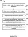
- FIG. 2 there is shown a flowchart illustrating an example method 200 for limiting power of an engine, such as engine 10 of Figure 1 . While the method 200 is described herein with reference to the engine 10 of Figure 1 , this is for example purposes. The method 200 may be applied to other types of engines depending on practical implementations.
- a blade angle is obtained.
- the blade angle may be obtained from one or more of the propeller blades 122.
- the blade angle is obtained from a blade angle measuring device comprising one or more sensors for measuring an angle of one or more propeller blades 122.
- the blade angle may be measured at a specific point along a length of one of the propeller blades 122.
- the obtained blade angle may be in degrees or radians.
- the blade angle may be obtained by measuring position or movement of a beta ring of the engine 10, where position of the beta ring depends on the blade angle.
- a beta valve may be connected to the propeller 120 through the beta ring, where the beta valve is for controlling the blade angle.
- the movement or position of the beta ring may be measured in inches, centimeters, and the like. From the movement or position of the beta ring, the blade angle may be determined.
- the blade angle of the propeller blade 122 is obtained from a control system or an aircraft engine computer configured for controlling the blade angle of the propeller blades 122.
- the blade angle may be obtained from a database associated with the control system or the aircraft engine computer.
- the blade angle may be dynamically obtained in real time when needed, or may be obtained regularly in accordance with any predetermined time interval.
- the blade angle may be actively retrieved, or may be passively received.
- the blade angle may be retrieved and/or received from the blade angle measuring device, the control system or the aircraft/engine computer.
- the blade angle is obtained via existing components as part of engine control and/or operation. Alternatively, the blade angle is simply provided for the purposes of method 200.
- the blade angle measuring device may be separate from the engine 10 and associated with other components of the aircraft.
- step 202 comprises triggering measurement of the blade angle whenever method 200 is initiated.
- a commanded power of the engine 10 is obtained.
- the commanded power of the engine 10 refers to a power being commanded by a pilot of the aircraft.
- the commanded power may correspond to a power commanded by one or more engine control levers controllable by the pilot.
- the one or more engine control levers may comprise one or more of a thrust lever, a power lever and/or any other suitable mechanism for commanding power of the engine 10.
- the commanded power of the engine 10 may be obtained based on the position of one or more engine control levers, for example, by monitoring the position of one or more engine control levers.
- the position of each engine control levers may be defined by an angle.
- the position of the power lever may be referred to as a power lever angle (PLA).
- PPA power lever angle
- the commanded power of the engine 10 is obtained based on the position of the PLA.
- the commanded power may be dynamically obtained in real time when needed, or may be obtained regularly in accordance with any predetermined time interval.
- the commanded power may be actively retrieved, or may be passively received.
- the commanded power may be retrieved and/or received from a commanded power measuring device comprising one or more sensors for measuring commanded power.
- the commanded power may be retrieved and/or received from one or more engine control levers, the control system or the aircraft/engine computer.
- the commanded power is obtained via existing components as part of engine control and/or operation.
- step 204 comprises triggering measurement of the commanded power whenever method 200 is initiated.
- Thrust refers to the force generated by the engine 10 through the propeller 120. Thrust of the engine 10 is generally dependent on the blade angle and a rotational speed of the propeller blades 122. In some embodiments, thrust of the engine 10 is forward thrust used to cause the aircraft to move forward. When the engine 10 is producing forward thrust, the blade angle of the propeller blade 122 is at a positive angle. In some embodiments, thrust of the engine 10 is reverse thrust used to cause the aircraft to move in reverse or is used for braking. When the engine 10 is producing reverse thrust, the blade angle of the propeller blade 122 is at a negative angle. The thrust transition direction may be a forward to reverse thrust transition or a reverse to forward thrust transition.
- the blade angle of the propeller blade 122 transitions from a positive blade angle to a negative blade angle and passes through the disking range.
- the blade angle of the propeller blade 122 transitions from a negative blade angle to a positive blade angle and passes through the disking range.
- Thrust may be controlled by one or more of the engine control levers.
- the one or more engine control levers may comprise one or more of a thrust lever, a power lever and/or any other suitable mechanism for controlling thrust of the engine 10.
- the engine control levers may comprise a mechanism for controlling thrust direction.
- the thrust transition direction may be determined based on the position of one or more engine control levers.
- the thrust transition direction may be determined by monitoring the one or more engine control levers, such as the mechanism for controlling the thrust direction.
- the thrust transition direction may be determined by dynamically obtaining in real time when needed the position of one or more engine control levers, or may be determined by obtaining regularly in accordance with any predetermined time interval the position of one or more engine control levers.
- the position of the one or more engine control levers may be actively retrieved, or may be passively received.
- the commanded power is compared to a selected threshold based on the blade angle and the thrust transition direction.
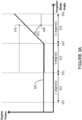
- a first threshold 301 and a second threshold 302 are respectively illustrated.
- One of the first threshold 301 and the second threshold 302 may be selected based on the blade angle and the thrust transition direction for the comparison of the commanded power thereto.
- the commanded power is compared to the first threshold 301 until the blade angle reaches a first transition angle 321 and the commanded power is compared to the second threshold 302 after the blade angle reaches the first transition angle 321.
- the first threshold 301 may be selected for the forward to reverse thrust transition while the blade angle is greater than the first transition angle 321 and the second threshold 302 may be selected while the blade angle is less than the first transition angle 321.
- the first transition angle 321 is a negative angle.
- the first transition angle 321 may be -1, -2, -3, -4, -5, -6, -7, -8, -9 degrees or any other suitable value.
- the first transition angle 321 may be in the range of -10 to - 0.1 degrees. Other values for the first transition angle 321 are also contemplated.
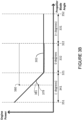
- the commanded power is compared to the second threshold 302 until the blade angle reaches a second transition angle 322 and the commanded power is compared to the first threshold 301 after the blade angle reaches the second transition angle 322.
- the second threshold 302 may be selected for the reverse to forward thrust transition while the blade angle is less than the second transition angle 322 and the first threshold 301 may be selected while the blade angle is greater than the second transition angle 322.
- the second transition angle 322 is a positive angle.
- the second transition angle 322 may be 1, 2, 3, 4, 5, 6, 7, 8, 9 degrees or any other suitable value.
- the second transition angle 322 may be in the range of 0.1 to 10 degrees. Other values for the second transition angle 322 are also contemplated.
- the first threshold 301 varies as a function of blade angle.
- the first threshold 301 may increase with increasing blade angle for a first positive range 331 of blade angles.
- the first threshold 301 may be constant for a second range 332 of blade angles, where the second range 332 is less than the first positive range 331.
- the first positive range 331 of blade angles is defined as a range between the second transition angle 322 and an upper endpoint 352. When the blade angle is greater than the upper endpoint 352, the thresholds 301, 302 may be disabled.
- the second threshold 302 varies as a function of blade angle.
- the second threshold 302 may decrease with increasing blade angle for a first negative range 341 of blade angles.
- the second threshold 302 may be constant for the second range 332 of blade angles, where the second range 332 is great than the first negative range 341.
- the first negative range 341 of blade angles is defined as a range between a lower endpoint 351 and the first transition angle 321. When the blade angle is less than the lower endpoint 351, the thresholds 301, 302 may be disabled.
- the second range 332 may be defined as a range between the first transition angle 321 and the second transition angle 322.
- the second range 332 may be selected such that all or part of the disking range is included within the second range 332.
- step 210 power to the engine 10 is limited when the commanded power exceeds the selected threshold.
- power to the engine 10 may be limited based on the first threshold 301.
- the pilot may additionally set the engine control lever from a first commanded power 369 to a second commanded power 370 in order to increase the commanded power.
- the first commanded power 369 and the second commanded power 370 illustrate commanded power as set by the engine control lever and not the actual power of the engine 10.
- Curve 371 illustrates the power of the engine 10 as a function of blade angle.
- the power of the engine (as illustrated by curve 371) is limited by the first threshold 301.
- the second threshold 302 is then selected to limit power to the engine 10, and is not described in this example.
- power to the engine 10 may be limited based on the second threshold 302.
- the pilot may additionally set the engine control lever from a third commanded power 379 to a fourth commanded power 380 in order to increase the commanded power.
- the third commanded power 379 and the fourth commanded power 380 illustrate commanded power as set by the engine control lever and not the actual power of the engine 10.
- Curve 381 illustrate the power of the engine 10 as a function of blade angle.
- the power of the engine (as illustrated by curve 381) is limited by the second threshold 302.
- the first threshold 301 is then selected to limit power to the engine 10, and is not described in this example.
- the power to the engine 10 may be limited in various manners.
- limiting power to the engine 10 may comprise limiting engine rotational speed by adjusting an engine rotational speed schedule used for controlling engine rotational speed as a function of engine power.
- a corrected core rotational speed (NgN) may be limited.
- power limits in one or more NgN schedules may be adjusted to limit power to the engine 10. This may be appropriate for systems where a propeller speed control has limited authority in the disking range and/or a reverse thrust range.
- limiting power to the engine 10 may comprises directly controlling the rotational speed of the propeller blade 122 by adjusting fuel flow to the engine 10. As torque is a function of the blade angle, limiting power to the engine 10 may be achieved by modulating a fuel flow based on a propeller speed limiter.
- the propeller speed limiter may be implemented by one or more schedules that varies with the ambient conditions, the engine control lever (e.g., the PLA) and/or the blade angle.
- an example propeller speed limiter 402 is shown. Additionally shown is a first curve 404 illustrating an example of rotational speed of the propeller blade 122 as a function of blade angle for a landing maneuver.
- a second curve 406 is also shown illustrating an example of the rotational speed of the propeller blade 122 as a function of blade angle for an on ground maneuver.
- the propeller speed limiter 402 varies as function of blade angle.
- the propeller speed limiter 402 has a first constant value for a reverse thrust range of blade angles 422 corresponding to reverse thrust of the engine 10, a second constant value for a disking range of blade angles 424 corresponding to a range where disking of the engine 10 occurs and a third constant value for a forward thrust range of blade angles 426 corresponding to forward thrust of the engine 10.
- limiting power to the engine 10 may comprise limiting rotational speed of the propeller blade such that rotational speed of the propeller blade 122 does not exceed the propeller speed limiter 402.
- limiting power to the engine 10 may comprises controlling one or more of variable inlet guide vanes, an electronically actuated bleed valve, a direct fuel flow schedule and/or any other suitable mechanical component and/or control system of the engine 10.
- Other manners for limiting power to the engine 10 are also contemplated.
- At least one threshold 301, 302 is selected for an entire range of movement of the engine control lever (e.g., the PLA).
- the first threshold 301 may be selected upon engine start.
- the first threshold 301 is selected.
- the first threshold 302 is selected.
- the blade angle is less than the first transition angle 321
- the threshold is switched from the first threshold 301 to the second threshold 302.
- the second threshold 302 is selected for all engine control lever movement while the blade angle is less than the second transition angle 322.
- the second threshold 302 is selected.
- the threshold is switched from the second threshold 302 to the first threshold 301.
- the thresholds 301, 302 are selected for only a specific range of movement of the engine control lever (e.g., the PLA). For example, neither the first threshold 301 nor the second threshold 302 is selected upon engine start. In other words, there may be no power limit on the engine 10 until the pilot commands reverse thrust by placing the engine control lever in reverse.
- the first threshold 301 could then be selected until the blade angle is less than the first transition angle 321, then the threshold is switched from the first threshold 301 to the second threshold 302.
- the second threshold is selected until the blade angle is greater than the second transition angle 322; afterwards, the threshold is switched from the second threshold 302 to the first threshold 301. After the blade angle is greater than the upper endpoint 352, the first threshold 301 is deactivated such that neither the first threshold 301 nor the second threshold 302 is selected.
- the effect of limiting power to engine 10 based on the thresholds 301, 302 is that protection of the engine 10 is not mechanically achieved through linkage or friction (e.g., by restricting movement of the one or more control levers) but through power limit on the engine 10. This protection is active even if the pilot slams the control lever to a maximum reverse power position from a forward thrust power or idle position and/or when the pilot slams the control lever to maximum takeoff position from a reverse thrust power position.
- the thresholds 301, 302 may be selected depending on the blade angle and the thrust transition direction.
- the selecting of the thresholds 301, 302 based on the blade angle and the thrust transition direction is designed to create hysteresis in limiting power to the engine 10 during the disking range. It may therefore prevent or reduce initial accelerations caused by the pilot slamming the control lever to the maximum reverse power position or a maximum takeoff position. That is, initial accelerations may occur if power to the engine 10 is initially increased before the blade angle reaches a point where a limiter is enabled and limits power to the engine 10.
- the thresholds 301, 302 may be dependent on operating conditions such as aircraft speed, altitude, air temperature and/or any other suitable ambient condition. Accordingly, the thresholds 301, 302 used in method 200 may be selected from a set of thresholds based on ambient conditions. For example, sensors may be used to measure the ambient conditions.
- the thresholds 301, 302 may be determined by computer simulation and/or engine tests.
- limiting the power to the engine 10 according to method 200 prevents the power of the engine 10 from being increased while the one or more propeller blades 122 cross the disking range.
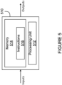
- the method 200 may be implemented by a computing device 510, comprising a processing unit 512 and a memory 514 which has stored therein computer-executable instructions 516.
- the processing unit 512 may comprise any suitable devices configured to implement the system such that instructions 516, when executed by the computing device 510 or other programmable apparatus, may cause the functions/acts/steps of the method 200 as described herein to be executed.
- the processing unit 512 may comprise, for example, any type of general-purpose microprocessor or microcontroller, a digital signal processing (DSP) processor, a central processing unit (CPU), an integrated circuit, a field programmable gate array (FPGA), a reconfigurable processor, other suitably programmed or programmable logic circuits, or any combination thereof.
- DSP digital signal processing
- CPU central processing unit
- FPGA field programmable gate array
- reconfigurable processor other suitably programmed or programmable logic circuits, or any combination thereof.
- the memory 514 may comprise any suitable known or other machine-readable storage medium.
- the memory 514 may comprise non-transitory computer readable storage medium, for example, but not limited to, an electronic, magnetic, optical, electromagnetic, infrared, or semiconductor system, apparatus, or device, or any suitable combination of the foregoing.
- the memory 514 may include a suitable combination of any type of computer memory that is located either internally or externally to device, for example random-access memory (RAM), read-only memory (ROM), compact disc read-only memory (CDROM), electro-optical memory, magnetooptical memory, erasable programmable read-only memory (EPROM), and electrically-erasable programmable read-only memory (EEPROM), Ferroelectric RAM (FRAM) or the like.
- RAM random-access memory
- ROM read-only memory
- CDROM compact disc read-only memory
- electro-optical memory magnetooptical memory
- EPROM erasable programmable read-only memory
- EEPROM electrically-erasable programm
- Memory 514 may comprise any storage means (e.g., devices) suitable for retrievably storing machine-readable instructions 516 executable by processing unit 512.
- the computing device 510 can be implemented as part of a full-authority digital engine controls (FADEC) or other similar device, including electronic engine control (EEC), engine control unit (EUC), and the like.
- FADEC full-authority digital engine controls
- EEC electronic engine control
- EUC engine control unit
- the methods and systems for limiting power described herein may be implemented in a high level procedural or object oriented programming or scripting language, or a combination thereof, to communicate with or assist in the operation of a computer system, for example the computing device 510.
- the methods and systems for limiting power may be implemented in assembly or machine language.
- the language may be a compiled or interpreted language.
- Program code for implementing the methods and systems for limiting power may be stored on a storage media or a device, for example a ROM, a magnetic disk, an optical disc, a flash drive, or any other suitable storage media or device.
- the program code may be readable by a general or special-purpose programmable computer for configuring and operating the computer when the storage media or device is read by the computer to perform the procedures described herein.
- Embodiments of the methods and systems for limiting power may also be considered to be implemented by way of a non-transitory computer-readable storage medium having a computer program stored thereon.
- the computer program may comprise computer-readable instructions which cause a computer, or in some embodiments the processing unit 512 of the computing device 510, to operate in a specific and predefined manner to perform the functions described herein.
- Computer-executable instructions may be in many forms, including program modules, executed by one or more computers or other devices.
- program modules include routines, programs, objects, components, data structures, etc., that perform particular tasks or implement particular abstract data types.
- functionality of the program modules may be combined or distributed as desired in various embodiments.
Landscapes
- Engineering & Computer Science (AREA)
- Chemical & Material Sciences (AREA)
- Combustion & Propulsion (AREA)
- Mechanical Engineering (AREA)
- General Engineering & Computer Science (AREA)
- Aviation & Aerospace Engineering (AREA)
- Automation & Control Theory (AREA)
- Control Of Turbines (AREA)
- Operation Control Of Excavators (AREA)
Claims (15)
- Verfahren (200) zum Begrenzen der Leistung eines Gasturbinentriebwerks (10) für ein Luftfahrzeug, wobei das Verfahren Folgendes umfasst:Erhalten eines Schaufelwinkels einer Propellerschaufel (122) des Triebwerks (10) und einer befohlenen Leistung für das Triebwerk (10); undBestimmen einer Schubübergangsrichtung des Triebwerks (10),gekennzeichnet durch:Auswählen eines Schwellenwerts (301, 302) basierend auf der Schubübergangsrichtung und dem Schaufelwinkel, wobei der Schwellenwert eine Leistungsgrenze für das Triebwerk (10) als eine Funktion des Schaufelwinkels für die Schubübergangsrichtung definiert;Vergleichen der befohlenen Leistung mit dem ausgewählten Schwellenwert (301, 302), basierend auf dem Schaufelwinkel und der Schubübergangsrichtung; undBegrenzen der Leistung des Triebwerks (10), wenn die befohlene Leistung den ausgewählten Schwellenwert (301, 302) überschreitet.
- Verfahren nach Anspruch 1, wobei das Vergleichen der befohlenen Leistung mit dem ausgewählten Schwellenwert (301, 302) Folgendes umfasst:wenn die Schubübergangsrichtung ein Vorwärts-Rückwärts-Schubübergang ist, Vergleichen der befohlenen Leistung mit einem ersten Schwellenwert (301), bis der Schaufelwinkel einen ersten Übergangswinkel (321) erreicht; undVergleichen der befohlenen Leistung mit einem zweiten Schwellenwert (302), nachdem der Schaufelwinkel den ersten Übergangswinkel (321) erreicht hat.
- Verfahren nach Anspruch 2, wobei der erste Schwellenwert (301) mit zunehmendem Schaufelwinkel für einen ersten positiven Bereich (331) von Schaufelwinkeln zunimmt und für einen zweiten Bereich (332) von Schaufelwinkeln konstant ist, wobei der zweite Bereich (332) kleiner als der erste positive Bereich (331) ist.
- Verfahren nach Anspruch 2 oder 3, wobei der zweite Schwellenwert (302) mit abnehmendem Schaufelwinkel für einen ersten negativen Bereich (341) von Schaufelwinkeln zunimmt und für einen zweiten Bereich (332) von Schaufelwinkeln konstant ist, wobei der zweite Bereich (332) größer als der erste negative Bereich (341) ist.
- Verfahren nach einem der vorhergehenden Ansprüche, wobei das Vergleichen der befohlenen Leistung mit dem ausgewählten Schwellenwert (301, 302) Folgendes umfasst:wenn die Schubübergangsrichtung ein Rückwärts-Vorwärts-Schubübergang ist, Vergleichen der befohlenen Leistung mit einem zweiten Schwellenwert (302), bis der Schaufelwinkel einen zweiten Übergangswinkel (322) erreicht; undVergleichen der befohlenen Leistung mit einem ersten Schwellenwert (301), nachdem der Schaufelwinkel den zweiten Übergangswinkel (322) erreicht hat.
- Verfahren nach einem der vorhergehenden Ansprüche, wobei das Begrenzen der Leistung des Triebwerks (10) Folgendes umfasst: Einstellen eines Triebwerksdrehzahlplans; direktes Steuern einer Drehzahl der Propellerschaufel (122) durch Einstellen des Kraftstoffflusses zu dem Triebwerk (10); oder Steuern einer oder mehrerer variabler Einlassleitschaufeln, eines elektronisch betätigten Ablassventils und eines direkten Kraftstoffflussplans.
- Verfahren nach einem der vorhergehenden Ansprüche, ferner umfassend das Auswählen des Schwellenwerts (301, 302) basierend auf den Umgebungsbedingungen.
- System zum Begrenzen der Leistung eines Gasturbinentriebwerks (10) für ein Luftfahrzeug, wobei das System Folgendes umfasst:eine Verarbeitungseinheit (512); undeinen nichtflüchtigen computerlesbaren Speicher (514), auf dem Programmanweisungen (516) gespeichert sind, die durch die Verarbeitungseinheit (512) für Folgendes ausführbar sind:Erhalten eines Schaufelwinkels einer Propellerschaufel (122) des Triebwerks (10) und einer befohlenen Leistung für das Triebwerk (10); undBestimmen einer Schubübergangsrichtung des Triebwerks (10), gekennzeichnet durch:Auswählen eines Schwellenwerts (301, 302) basierend auf der Schubübergangsrichtung und dem Schaufelwinkel, wobei der Schwellenwert eine Leistungsgrenze für das Triebwerk (10) als eine Funktion des Schaufelwinkels für die Schubübergangsrichtung definiert;Vergleichen der befohlenen Leistung mit dem ausgewählten Schwellenwert (301, 302), basierend auf dem Schaufelwinkel und der Schubübergangsrichtung; undBegrenzen der Leistung des Triebwerks (10), wenn die befohlene Leistung den ausgewählten Schwellenwert (301, 302) überschreitet.
- System nach Anspruch 8, wobei das Vergleichen der befohlenen Leistung mit dem ausgewählten Schwellenwert (301, 302) Folgendes umfasst:wenn die Schubübergangsrichtung ein Vorwärts-Rückwärts-Schubübergang ist, Vergleichen der befohlenen Leistung mit einem ersten Schwellenwert (301), bis der Schaufelwinkel einen ersten Übergangswinkel (321) erreicht; undVergleichen der befohlenen Leistung mit einem zweiten Schwellenwert (302), nachdem der Schaufelwinkel den ersten Übergangswinkel (321) erreicht hat.
- System nach Anspruch 9, wobei der erste Schwellenwert (301) mit zunehmendem Schaufelwinkel für einen ersten positiven Bereich (331) von Schaufelwinkeln zunimmt und für einen zweiten Bereich (332) von Schaufelwinkeln konstant ist, wobei der zweite Bereich (332) kleiner als der erste positive Bereich (331) ist.
- System nach Anspruch 9 oder 10, wobei der zweite Schwellenwert (302) mit abnehmendem Schaufelwinkel für einen ersten negativen Bereich (341) von Schaufelwinkeln zunimmt und für einen zweiten Bereich (332) von Schaufelwinkeln konstant ist, wobei der zweite Bereich (332) größer als der erste negative Bereich (341) ist.
- System nach einem der Ansprüche 8 bis 11, wobei das Vergleichen der befohlenen Leistung mit dem ausgewählten Schwellenwert (301, 302) Folgendes umfasst:wenn die Schubübergangsrichtung ein Rückwärts-Vorwärts-Schubübergang ist, Vergleichen der befohlenen Leistung mit einem zweiten Schwellenwert (302), bis der Schaufelwinkel einen zweiten Übergangswinkel (322) erreicht; undVergleichen der befohlenen Leistung mit einem ersten Schwellenwert (301), nachdem der Schaufelwinkel den zweiten Übergangswinkel (322) erreicht hat.
- System nach einem der Ansprüche 8 bis 12, wobei das Begrenzen der Leistung des Triebwerks (10) Folgendes umfasst: Einstellen eines Triebwerksdrehzahlplans; direktes Steuern einer Drehzahl der Propellerschaufel (122) durch Einstellen des Kraftstoffflusses zu dem Triebwerk (10); oder Steuern einer oder mehrerer variabler Einlassleitschaufeln, eines elektronisch betätigten Ablassventils und eines direkten Kraftstoffflussplans.
- System nach einem der Ansprüche 8 bis 13, wobei die Programmanweisungen (516) ferner von der Verarbeitungseinheit (512) ausführbar sind, um den Schwellenwert (301, 302) basierend auf den Umgebungsbedingungen auszuwählen.
- Nichtflüchtiges computerlesbares Medium (514), auf dem Programmanweisungen (516) zum Begrenzen der Leistung eines Gasturbinentriebwerks (10) für ein Luftfahrzeug gespeichert sind, wobei die Programmanweisungen (516) von einer Verarbeitungseinheit (512) ausgeführt werden können, zum:Erhalten eines Schaufelwinkels einer Propellerschaufel (122) des Triebwerks (10) und einer befohlenen Leistung für das Triebwerk (10); undBestimmen einer Schubübergangsrichtung des Triebwerks (10) gekennzeichnet durch:Auswählen eines Schwellenwerts (301, 302) basierend auf der Schubübergangsrichtung und dem Schaufelwinkel, wobei der Schwellenwert eine Leistungsgrenze für das Triebwerk (10) als eine Funktion des Schaufelwinkels für die Schubübergangsrichtung definiert;Vergleichen der befohlenen Leistung mit dem ausgewählten Schwellenwert (301, 302), basierend auf dem Schaufelwinkel und der Schubübergangsrichtung; undBegrenzen der Leistung des Triebwerks, wenn die befohlene Leistung den ausgewählten Schwellenwert (301, 302) überschreitet.
Applications Claiming Priority (1)
| Application Number | Priority Date | Filing Date | Title |
|---|---|---|---|
| US15/681,531 US10823113B2 (en) | 2017-08-21 | 2017-08-21 | Method and system for limiting power of an engine |
Publications (2)
| Publication Number | Publication Date |
|---|---|
| EP3447269A1 EP3447269A1 (de) | 2019-02-27 |
| EP3447269B1 true EP3447269B1 (de) | 2024-07-31 |
Family
ID=63350472
Family Applications (1)
| Application Number | Title | Priority Date | Filing Date |
|---|---|---|---|
| EP18190084.6A Active EP3447269B1 (de) | 2017-08-21 | 2018-08-21 | Verfahren und system zur begrenzung der leistung einer gasturbine |
Country Status (4)
| Country | Link |
|---|---|
| US (1) | US10823113B2 (de) |
| EP (1) | EP3447269B1 (de) |
| CA (1) | CA3013601A1 (de) |
| PL (1) | PL3447269T3 (de) |
Families Citing this family (7)
| Publication number | Priority date | Publication date | Assignee | Title |
|---|---|---|---|---|
| US11414175B2 (en) * | 2019-04-01 | 2022-08-16 | Pratt & Whitney Canada Corp. | Method and system for operating an aircraft powerplant |
| US12078074B2 (en) * | 2019-05-13 | 2024-09-03 | Pratt & Whitney Canada Corp. | System and method for detecting an uncommanded or uncontrollable high thrust event in an aircraft |
| US20210070458A1 (en) * | 2019-09-06 | 2021-03-11 | Hamilton Sundstrand Corporation | Vortex turbines for a hybrid-electric aircraft |
| US11668253B2 (en) * | 2020-10-16 | 2023-06-06 | Pratt & Whitney Canada Corp. | System and method for providing in-flight reverse thrust for an aircraft |
| US11719167B2 (en) * | 2021-04-01 | 2023-08-08 | Pratt & Whitney Canada Corp. | Operating a turboprop engine for in-flight restart |
| CN113586277A (zh) * | 2021-07-21 | 2021-11-02 | 上海外高桥造船有限公司 | 船上主机功率限制系统及方法 |
| US12006883B2 (en) | 2022-02-04 | 2024-06-11 | Pratt & Whitney Canada Corp. | Method and system of operating an airplane engine |
Family Cites Families (23)
| Publication number | Priority date | Publication date | Assignee | Title |
|---|---|---|---|---|
| US2640550A (en) * | 1948-07-24 | 1953-06-02 | Curtiss Wright Corp | Turbine propeller control system |
| US2737252A (en) * | 1950-06-01 | 1956-03-06 | Curtiss Wright Corp | Turbine propeller control system |
| US3936226A (en) | 1974-06-07 | 1976-02-03 | United Technologies Corporation | Control system for variable pitch fan propulsor with reverse pitch |
| US4258545A (en) | 1978-06-15 | 1981-03-31 | General Electric Company | Optimal control for a gas turbine engine |
| US4958289A (en) * | 1988-12-14 | 1990-09-18 | General Electric Company | Aircraft propeller speed control |
| GB0027288D0 (en) | 2000-11-08 | 2000-12-27 | Rolls Royce Plc | Overthrust protection system and method |
| US6578794B1 (en) | 2000-11-28 | 2003-06-17 | General Electric Co. | Methods and systems for jet engine overthrust protection |
| US6704630B2 (en) | 2002-04-04 | 2004-03-09 | Grazyna Balut Ostrom | Thrust control malfunction accommodation system and method |
| DE10302074A1 (de) | 2003-01-21 | 2004-07-29 | Rolls-Royce Deutschland Ltd & Co Kg | Fehlerdetektionslogik für Triebwerke |
| US8651811B2 (en) | 2005-11-16 | 2014-02-18 | Hamilton Sundstrand | Control logic for a propeller system |
| US8414260B2 (en) | 2006-07-25 | 2013-04-09 | Lockheed Martin Corporation | Control system for controlling propeller aircraft engine during takeoff |
| US8954228B2 (en) | 2008-12-30 | 2015-02-10 | Rolls-Royce Corporation | Gas turbine engine failure detection |
| GB201201093D0 (en) | 2012-01-24 | 2012-03-07 | Rolls Royce Plc | Improvements in or relating to control systems for machines |
| FR2996254B1 (fr) | 2012-10-03 | 2014-09-12 | Snecma | Methode de surveillance d'un defaut de poussee d'un turboreacteur d'aeronef |
| GB201301791D0 (en) | 2013-02-01 | 2013-03-20 | Rolls Royce Engine Control Systems Ltd | Engine fuel control system |
| GB201313142D0 (en) | 2013-07-23 | 2013-09-04 | Rolls Royce Engine Control Systems Ltd | Engine Fuel Control System |
| GB201412189D0 (en) | 2014-07-09 | 2014-08-20 | Rolls Royce Plc | A nozzle arrangement for a gas turbine engine |
| EP3018054B1 (de) | 2014-11-07 | 2019-01-02 | Airbus Defence and Space, S.A. | Verfahren zur Steuerung eines Flugzeugpropellersystems während der Schubumkehr |
| US9494085B2 (en) | 2015-01-19 | 2016-11-15 | United Technologies Corporation | System and method for load power management in a turboshaft gas turbine engine |
| US10487752B2 (en) | 2015-03-11 | 2019-11-26 | Pratt & Whitney Canada Corp. | Overthrust protection system and method |
| US9932906B2 (en) | 2015-09-23 | 2018-04-03 | Honeywell International Inc. | Gas turbine engine uncontrolled high thrust detection system and method |
| US9771878B2 (en) * | 2015-10-19 | 2017-09-26 | General Electric Company | Thrust scheduling method for variable pitch fan engines and turbo-shaft, turbo-propeller engines |
| US10279918B2 (en) | 2016-08-31 | 2019-05-07 | The Boeing Company | Methods and apparatus to control thrust ramping of an aircraft engine |
-
2017
- 2017-08-21 US US15/681,531 patent/US10823113B2/en active Active
-
2018
- 2018-08-07 CA CA3013601A patent/CA3013601A1/en active Pending
- 2018-08-21 EP EP18190084.6A patent/EP3447269B1/de active Active
- 2018-08-21 PL PL18190084.6T patent/PL3447269T3/pl unknown
Also Published As
| Publication number | Publication date |
|---|---|
| EP3447269A1 (de) | 2019-02-27 |
| US20190055901A1 (en) | 2019-02-21 |
| PL3447269T3 (pl) | 2024-10-14 |
| CA3013601A1 (en) | 2019-02-21 |
| US10823113B2 (en) | 2020-11-03 |
Similar Documents
| Publication | Publication Date | Title |
|---|---|---|
| EP3447269B1 (de) | Verfahren und system zur begrenzung der leistung einer gasturbine | |
| US11999499B2 (en) | Autothrottle control for turboprop engines | |
| EP3718882B1 (de) | Verfahren und system zum betrieb eines flugzeugtriebwerks | |
| EP3741666B1 (de) | Verfahren zur steuerung eines propellers mit zweipositionselektromagneten | |
| EP3403923A1 (de) | System und verfahren zur flugzeugpropellersteuerung | |
| US20200232395A1 (en) | Method and system for operating a gas turbine engine coupled to an aircraft propeller | |
| US20190078517A1 (en) | Method and system for directing fuel flow to an engine | |
| CN111924127B (zh) | 检测飞行器中的无命令或不可控高推力事件的系统和方法 | |
| CA3002287A1 (en) | Detection of uncommanded and uncontrollable high thrust events | |
| US10946972B2 (en) | Method and system for controlling thrust of an engine | |
| EP3623608B1 (de) | Verfahren und system zur einstellung eines variablen geometriemechanismus | |
| CN110886659B (zh) | 用于限制发动机功率的方法及系统 | |
| EP4067635B1 (de) | Betrieb eines turbopropmotors für einen neustart während des flugs | |
| CN110884653B (zh) | 用于飞行器螺旋桨控制的系统和方法 |
Legal Events
| Date | Code | Title | Description |
|---|---|---|---|
| PUAI | Public reference made under article 153(3) epc to a published international application that has entered the european phase |
Free format text: ORIGINAL CODE: 0009012 |
|
| STAA | Information on the status of an ep patent application or granted ep patent |
Free format text: STATUS: THE APPLICATION HAS BEEN PUBLISHED |
|
| AK | Designated contracting states |
Kind code of ref document: A1 Designated state(s): AL AT BE BG CH CY CZ DE DK EE ES FI FR GB GR HR HU IE IS IT LI LT LU LV MC MK MT NL NO PL PT RO RS SE SI SK SM TR |
|
| AX | Request for extension of the european patent |
Extension state: BA ME |
|
| STAA | Information on the status of an ep patent application or granted ep patent |
Free format text: STATUS: REQUEST FOR EXAMINATION WAS MADE |
|
| 17P | Request for examination filed |
Effective date: 20190827 |
|
| RBV | Designated contracting states (corrected) |
Designated state(s): AL AT BE BG CH CY CZ DE DK EE ES FI FR GB GR HR HU IE IS IT LI LT LU LV MC MK MT NL NO PL PT RO RS SE SI SK SM TR |
|
| STAA | Information on the status of an ep patent application or granted ep patent |
Free format text: STATUS: EXAMINATION IS IN PROGRESS |
|
| 17Q | First examination report despatched |
Effective date: 20210421 |
|
| GRAP | Despatch of communication of intention to grant a patent |
Free format text: ORIGINAL CODE: EPIDOSNIGR1 |
|
| STAA | Information on the status of an ep patent application or granted ep patent |
Free format text: STATUS: GRANT OF PATENT IS INTENDED |
|
| INTG | Intention to grant announced |
Effective date: 20240219 |
|
| GRAS | Grant fee paid |
Free format text: ORIGINAL CODE: EPIDOSNIGR3 |
|
| GRAA | (expected) grant |
Free format text: ORIGINAL CODE: 0009210 |
|
| STAA | Information on the status of an ep patent application or granted ep patent |
Free format text: STATUS: THE PATENT HAS BEEN GRANTED |
|
| AK | Designated contracting states |
Kind code of ref document: B1 Designated state(s): AL AT BE BG CH CY CZ DE DK EE ES FI FR GB GR HR HU IE IS IT LI LT LU LV MC MK MT NL NO PL PT RO RS SE SI SK SM TR |
|
| REG | Reference to a national code |
Ref country code: CH Ref legal event code: EP Ref country code: GB Ref legal event code: FG4D |
|
| REG | Reference to a national code |
Ref country code: DE Ref legal event code: R096 Ref document number: 602018072385 Country of ref document: DE |
|
| REG | Reference to a national code |
Ref country code: IE Ref legal event code: FG4D |
|
| REG | Reference to a national code |
Ref country code: LT Ref legal event code: MG9D |
|
| REG | Reference to a national code |
Ref country code: NL Ref legal event code: MP Effective date: 20240731 |
|
| PG25 | Lapsed in a contracting state [announced via postgrant information from national office to epo] |
Ref country code: PT Free format text: LAPSE BECAUSE OF FAILURE TO SUBMIT A TRANSLATION OF THE DESCRIPTION OR TO PAY THE FEE WITHIN THE PRESCRIBED TIME-LIMIT Effective date: 20241202 |
|
| REG | Reference to a national code |
Ref country code: AT Ref legal event code: MK05 Ref document number: 1708655 Country of ref document: AT Kind code of ref document: T Effective date: 20240731 |
|
| PG25 | Lapsed in a contracting state [announced via postgrant information from national office to epo] |
Ref country code: PT Free format text: LAPSE BECAUSE OF FAILURE TO SUBMIT A TRANSLATION OF THE DESCRIPTION OR TO PAY THE FEE WITHIN THE PRESCRIBED TIME-LIMIT Effective date: 20241202 |
|
| PG25 | Lapsed in a contracting state [announced via postgrant information from national office to epo] |
Ref country code: NO Free format text: LAPSE BECAUSE OF FAILURE TO SUBMIT A TRANSLATION OF THE DESCRIPTION OR TO PAY THE FEE WITHIN THE PRESCRIBED TIME-LIMIT Effective date: 20241031 |
|
| PG25 | Lapsed in a contracting state [announced via postgrant information from national office to epo] |
Ref country code: NL Free format text: LAPSE BECAUSE OF FAILURE TO SUBMIT A TRANSLATION OF THE DESCRIPTION OR TO PAY THE FEE WITHIN THE PRESCRIBED TIME-LIMIT Effective date: 20240731 Ref country code: FI Free format text: LAPSE BECAUSE OF FAILURE TO SUBMIT A TRANSLATION OF THE DESCRIPTION OR TO PAY THE FEE WITHIN THE PRESCRIBED TIME-LIMIT Effective date: 20240731 Ref country code: GR Free format text: LAPSE BECAUSE OF FAILURE TO SUBMIT A TRANSLATION OF THE DESCRIPTION OR TO PAY THE FEE WITHIN THE PRESCRIBED TIME-LIMIT Effective date: 20241101 |
|
| PG25 | Lapsed in a contracting state [announced via postgrant information from national office to epo] |
Ref country code: BG Free format text: LAPSE BECAUSE OF FAILURE TO SUBMIT A TRANSLATION OF THE DESCRIPTION OR TO PAY THE FEE WITHIN THE PRESCRIBED TIME-LIMIT Effective date: 20240731 |
|
| PG25 | Lapsed in a contracting state [announced via postgrant information from national office to epo] |
Ref country code: LV Free format text: LAPSE BECAUSE OF FAILURE TO SUBMIT A TRANSLATION OF THE DESCRIPTION OR TO PAY THE FEE WITHIN THE PRESCRIBED TIME-LIMIT Effective date: 20240731 |
|
| PG25 | Lapsed in a contracting state [announced via postgrant information from national office to epo] |
Ref country code: AT Free format text: LAPSE BECAUSE OF FAILURE TO SUBMIT A TRANSLATION OF THE DESCRIPTION OR TO PAY THE FEE WITHIN THE PRESCRIBED TIME-LIMIT Effective date: 20240731 Ref country code: IS Free format text: LAPSE BECAUSE OF FAILURE TO SUBMIT A TRANSLATION OF THE DESCRIPTION OR TO PAY THE FEE WITHIN THE PRESCRIBED TIME-LIMIT Effective date: 20241130 |
|
| PG25 | Lapsed in a contracting state [announced via postgrant information from national office to epo] |
Ref country code: HR Free format text: LAPSE BECAUSE OF FAILURE TO SUBMIT A TRANSLATION OF THE DESCRIPTION OR TO PAY THE FEE WITHIN THE PRESCRIBED TIME-LIMIT Effective date: 20240731 |
|
| PG25 | Lapsed in a contracting state [announced via postgrant information from national office to epo] |
Ref country code: ES Free format text: LAPSE BECAUSE OF FAILURE TO SUBMIT A TRANSLATION OF THE DESCRIPTION OR TO PAY THE FEE WITHIN THE PRESCRIBED TIME-LIMIT Effective date: 20240731 Ref country code: RS Free format text: LAPSE BECAUSE OF FAILURE TO SUBMIT A TRANSLATION OF THE DESCRIPTION OR TO PAY THE FEE WITHIN THE PRESCRIBED TIME-LIMIT Effective date: 20241031 |
|
| PG25 | Lapsed in a contracting state [announced via postgrant information from national office to epo] |
Ref country code: RS Free format text: LAPSE BECAUSE OF FAILURE TO SUBMIT A TRANSLATION OF THE DESCRIPTION OR TO PAY THE FEE WITHIN THE PRESCRIBED TIME-LIMIT Effective date: 20241031 Ref country code: NO Free format text: LAPSE BECAUSE OF FAILURE TO SUBMIT A TRANSLATION OF THE DESCRIPTION OR TO PAY THE FEE WITHIN THE PRESCRIBED TIME-LIMIT Effective date: 20241031 Ref country code: NL Free format text: LAPSE BECAUSE OF FAILURE TO SUBMIT A TRANSLATION OF THE DESCRIPTION OR TO PAY THE FEE WITHIN THE PRESCRIBED TIME-LIMIT Effective date: 20240731 Ref country code: LV Free format text: LAPSE BECAUSE OF FAILURE TO SUBMIT A TRANSLATION OF THE DESCRIPTION OR TO PAY THE FEE WITHIN THE PRESCRIBED TIME-LIMIT Effective date: 20240731 Ref country code: IS Free format text: LAPSE BECAUSE OF FAILURE TO SUBMIT A TRANSLATION OF THE DESCRIPTION OR TO PAY THE FEE WITHIN THE PRESCRIBED TIME-LIMIT Effective date: 20241130 Ref country code: HR Free format text: LAPSE BECAUSE OF FAILURE TO SUBMIT A TRANSLATION OF THE DESCRIPTION OR TO PAY THE FEE WITHIN THE PRESCRIBED TIME-LIMIT Effective date: 20240731 Ref country code: GR Free format text: LAPSE BECAUSE OF FAILURE TO SUBMIT A TRANSLATION OF THE DESCRIPTION OR TO PAY THE FEE WITHIN THE PRESCRIBED TIME-LIMIT Effective date: 20241101 Ref country code: FI Free format text: LAPSE BECAUSE OF FAILURE TO SUBMIT A TRANSLATION OF THE DESCRIPTION OR TO PAY THE FEE WITHIN THE PRESCRIBED TIME-LIMIT Effective date: 20240731 Ref country code: ES Free format text: LAPSE BECAUSE OF FAILURE TO SUBMIT A TRANSLATION OF THE DESCRIPTION OR TO PAY THE FEE WITHIN THE PRESCRIBED TIME-LIMIT Effective date: 20240731 Ref country code: BG Free format text: LAPSE BECAUSE OF FAILURE TO SUBMIT A TRANSLATION OF THE DESCRIPTION OR TO PAY THE FEE WITHIN THE PRESCRIBED TIME-LIMIT Effective date: 20240731 Ref country code: AT Free format text: LAPSE BECAUSE OF FAILURE TO SUBMIT A TRANSLATION OF THE DESCRIPTION OR TO PAY THE FEE WITHIN THE PRESCRIBED TIME-LIMIT Effective date: 20240731 |
|
| REG | Reference to a national code |
Ref country code: CH Ref legal event code: PL |
|
| PG25 | Lapsed in a contracting state [announced via postgrant information from national office to epo] |
Ref country code: SM Free format text: LAPSE BECAUSE OF FAILURE TO SUBMIT A TRANSLATION OF THE DESCRIPTION OR TO PAY THE FEE WITHIN THE PRESCRIBED TIME-LIMIT Effective date: 20240731 Ref country code: DK Free format text: LAPSE BECAUSE OF FAILURE TO SUBMIT A TRANSLATION OF THE DESCRIPTION OR TO PAY THE FEE WITHIN THE PRESCRIBED TIME-LIMIT Effective date: 20240731 Ref country code: RO Free format text: LAPSE BECAUSE OF FAILURE TO SUBMIT A TRANSLATION OF THE DESCRIPTION OR TO PAY THE FEE WITHIN THE PRESCRIBED TIME-LIMIT Effective date: 20240731 |
|
| PG25 | Lapsed in a contracting state [announced via postgrant information from national office to epo] |
Ref country code: LU Free format text: LAPSE BECAUSE OF NON-PAYMENT OF DUE FEES Effective date: 20240821 |
|
| PG25 | Lapsed in a contracting state [announced via postgrant information from national office to epo] |
Ref country code: MC Free format text: LAPSE BECAUSE OF FAILURE TO SUBMIT A TRANSLATION OF THE DESCRIPTION OR TO PAY THE FEE WITHIN THE PRESCRIBED TIME-LIMIT Effective date: 20240731 Ref country code: CH Free format text: LAPSE BECAUSE OF NON-PAYMENT OF DUE FEES Effective date: 20240831 Ref country code: EE Free format text: LAPSE BECAUSE OF FAILURE TO SUBMIT A TRANSLATION OF THE DESCRIPTION OR TO PAY THE FEE WITHIN THE PRESCRIBED TIME-LIMIT Effective date: 20240731 |
|
| PG25 | Lapsed in a contracting state [announced via postgrant information from national office to epo] |
Ref country code: SK Free format text: LAPSE BECAUSE OF FAILURE TO SUBMIT A TRANSLATION OF THE DESCRIPTION OR TO PAY THE FEE WITHIN THE PRESCRIBED TIME-LIMIT Effective date: 20240731 Ref country code: IT Free format text: LAPSE BECAUSE OF FAILURE TO SUBMIT A TRANSLATION OF THE DESCRIPTION OR TO PAY THE FEE WITHIN THE PRESCRIBED TIME-LIMIT Effective date: 20240731 |
|
| REG | Reference to a national code |
Ref country code: DE Ref legal event code: R097 Ref document number: 602018072385 Country of ref document: DE |
|
| PLBE | No opposition filed within time limit |
Free format text: ORIGINAL CODE: 0009261 |
|
| STAA | Information on the status of an ep patent application or granted ep patent |
Free format text: STATUS: NO OPPOSITION FILED WITHIN TIME LIMIT |
|
| REG | Reference to a national code |
Ref country code: BE Ref legal event code: MM Effective date: 20240831 |
|
| 26N | No opposition filed |
Effective date: 20250501 |
|
| PG25 | Lapsed in a contracting state [announced via postgrant information from national office to epo] |
Ref country code: BE Free format text: LAPSE BECAUSE OF NON-PAYMENT OF DUE FEES Effective date: 20240831 |
|
| PG25 | Lapsed in a contracting state [announced via postgrant information from national office to epo] |
Ref country code: IE Free format text: LAPSE BECAUSE OF NON-PAYMENT OF DUE FEES Effective date: 20240821 |
|
| PG25 | Lapsed in a contracting state [announced via postgrant information from national office to epo] |
Ref country code: SE Free format text: LAPSE BECAUSE OF FAILURE TO SUBMIT A TRANSLATION OF THE DESCRIPTION OR TO PAY THE FEE WITHIN THE PRESCRIBED TIME-LIMIT Effective date: 20240731 |
|
| PGFP | Annual fee paid to national office [announced via postgrant information from national office to epo] |
Ref country code: DE Payment date: 20250724 Year of fee payment: 8 |
|
| PGFP | Annual fee paid to national office [announced via postgrant information from national office to epo] |
Ref country code: PL Payment date: 20250724 Year of fee payment: 8 |
|
| PGFP | Annual fee paid to national office [announced via postgrant information from national office to epo] |
Ref country code: GB Payment date: 20250725 Year of fee payment: 8 |
|
| PGFP | Annual fee paid to national office [announced via postgrant information from national office to epo] |
Ref country code: FR Payment date: 20250725 Year of fee payment: 8 |
|
| PGFP | Annual fee paid to national office [announced via postgrant information from national office to epo] |
Ref country code: CZ Payment date: 20250730 Year of fee payment: 8 |