EP3447033A1 - Method for manufacturing glass ingot - Google Patents
Method for manufacturing glass ingot Download PDFInfo
- Publication number
- EP3447033A1 EP3447033A1 EP17785785.1A EP17785785A EP3447033A1 EP 3447033 A1 EP3447033 A1 EP 3447033A1 EP 17785785 A EP17785785 A EP 17785785A EP 3447033 A1 EP3447033 A1 EP 3447033A1
- Authority
- EP
- European Patent Office
- Prior art keywords
- raw material
- oxygen
- gasifier
- concentration
- flow path
- Prior art date
- Legal status (The legal status is an assumption and is not a legal conclusion. Google has not performed a legal analysis and makes no representation as to the accuracy of the status listed.)
- Granted
Links
Images

Classifications
-
- C—CHEMISTRY; METALLURGY
- C03—GLASS; MINERAL OR SLAG WOOL
- C03B—MANUFACTURE, SHAPING, OR SUPPLEMENTARY PROCESSES
- C03B37/00—Manufacture or treatment of flakes, fibres, or filaments from softened glass, minerals, or slags
- C03B37/01—Manufacture of glass fibres or filaments
- C03B37/012—Manufacture of preforms for drawing fibres or filaments
- C03B37/014—Manufacture of preforms for drawing fibres or filaments made entirely or partially by chemical means, e.g. vapour phase deposition of bulk porous glass either by outside vapour deposition [OVD], or by outside vapour phase oxidation [OVPO] or by vapour axial deposition [VAD]
- C03B37/01413—Reactant delivery systems
-
- C—CHEMISTRY; METALLURGY
- C03—GLASS; MINERAL OR SLAG WOOL
- C03B—MANUFACTURE, SHAPING, OR SUPPLEMENTARY PROCESSES
- C03B37/00—Manufacture or treatment of flakes, fibres, or filaments from softened glass, minerals, or slags
- C03B37/01—Manufacture of glass fibres or filaments
- C03B37/012—Manufacture of preforms for drawing fibres or filaments
- C03B37/014—Manufacture of preforms for drawing fibres or filaments made entirely or partially by chemical means, e.g. vapour phase deposition of bulk porous glass either by outside vapour deposition [OVD], or by outside vapour phase oxidation [OVPO] or by vapour axial deposition [VAD]
- C03B37/018—Manufacture of preforms for drawing fibres or filaments made entirely or partially by chemical means, e.g. vapour phase deposition of bulk porous glass either by outside vapour deposition [OVD], or by outside vapour phase oxidation [OVPO] or by vapour axial deposition [VAD] by glass deposition on a glass substrate, e.g. by inside-, modified-, plasma- or plasma modified- chemical vapour deposition [ICVD, MCVD, PCVD, PMCVD], i.e. by thin layer coating on the inside or outside of a glass tube or on a glass rod
- C03B37/01807—Reactant delivery systems, e.g. reactant deposition burners
- C03B37/01815—Reactant deposition burners or deposition heating means
-
- C—CHEMISTRY; METALLURGY
- C03—GLASS; MINERAL OR SLAG WOOL
- C03B—MANUFACTURE, SHAPING, OR SUPPLEMENTARY PROCESSES
- C03B37/00—Manufacture or treatment of flakes, fibres, or filaments from softened glass, minerals, or slags
- C03B37/01—Manufacture of glass fibres or filaments
- C03B37/012—Manufacture of preforms for drawing fibres or filaments
- C03B37/014—Manufacture of preforms for drawing fibres or filaments made entirely or partially by chemical means, e.g. vapour phase deposition of bulk porous glass either by outside vapour deposition [OVD], or by outside vapour phase oxidation [OVPO] or by vapour axial deposition [VAD]
- C03B37/018—Manufacture of preforms for drawing fibres or filaments made entirely or partially by chemical means, e.g. vapour phase deposition of bulk porous glass either by outside vapour deposition [OVD], or by outside vapour phase oxidation [OVPO] or by vapour axial deposition [VAD] by glass deposition on a glass substrate, e.g. by inside-, modified-, plasma- or plasma modified- chemical vapour deposition [ICVD, MCVD, PCVD, PMCVD], i.e. by thin layer coating on the inside or outside of a glass tube or on a glass rod
-
- C—CHEMISTRY; METALLURGY
- C03—GLASS; MINERAL OR SLAG WOOL
- C03B—MANUFACTURE, SHAPING, OR SUPPLEMENTARY PROCESSES
- C03B37/00—Manufacture or treatment of flakes, fibres, or filaments from softened glass, minerals, or slags
- C03B37/01—Manufacture of glass fibres or filaments
- C03B37/02—Manufacture of glass fibres or filaments by drawing or extruding, e.g. direct drawing of molten glass from nozzles; Cooling fins therefor
- C03B37/025—Manufacture of glass fibres or filaments by drawing or extruding, e.g. direct drawing of molten glass from nozzles; Cooling fins therefor from reheated softened tubes, rods, fibres or filaments, e.g. drawing fibres from preforms
- C03B37/027—Fibres composed of different sorts of glass, e.g. glass optical fibres
-
- C—CHEMISTRY; METALLURGY
- C03—GLASS; MINERAL OR SLAG WOOL
- C03B—MANUFACTURE, SHAPING, OR SUPPLEMENTARY PROCESSES
- C03B19/00—Other methods of shaping glass
- C03B19/14—Other methods of shaping glass by gas- or vapour- phase reaction processes
- C03B19/1415—Reactant delivery systems
-
- C—CHEMISTRY; METALLURGY
- C03—GLASS; MINERAL OR SLAG WOOL
- C03B—MANUFACTURE, SHAPING, OR SUPPLEMENTARY PROCESSES
- C03B2201/00—Type of glass produced
- C03B2201/02—Pure silica glass, e.g. pure fused quartz
-
- C—CHEMISTRY; METALLURGY
- C03—GLASS; MINERAL OR SLAG WOOL
- C03B—MANUFACTURE, SHAPING, OR SUPPLEMENTARY PROCESSES
- C03B2207/00—Glass deposition burners
- C03B2207/30—For glass precursor of non-standard type, e.g. solid SiH3F
- C03B2207/32—Non-halide
-
- C—CHEMISTRY; METALLURGY
- C03—GLASS; MINERAL OR SLAG WOOL
- C03B—MANUFACTURE, SHAPING, OR SUPPLEMENTARY PROCESSES
- C03B2207/00—Glass deposition burners
- C03B2207/36—Fuel or oxidant details, e.g. flow rate, flow rate ratio, fuel additives
-
- C—CHEMISTRY; METALLURGY
- C03—GLASS; MINERAL OR SLAG WOOL
- C03B—MANUFACTURE, SHAPING, OR SUPPLEMENTARY PROCESSES
- C03B2207/00—Glass deposition burners
- C03B2207/46—Comprising performance enhancing means, e.g. electrostatic charge or built-in heater
-
- C—CHEMISTRY; METALLURGY
- C03—GLASS; MINERAL OR SLAG WOOL
- C03B—MANUFACTURE, SHAPING, OR SUPPLEMENTARY PROCESSES
- C03B2207/00—Glass deposition burners
- C03B2207/80—Feeding the burner or the burner-heated deposition site
Definitions
- the present invention relates to a method for manufacturing a glass ingot.
- a method for manufacturing a glass ingot such as a preform for an optical fiber for example, there is a method in which a soot deposit is produced by depositing SiO 2 fine particles and is heated, thereby obtaining a glass ingot (for example, refer to Patent Document 1).
- a manufacturing apparatus provided with a supply system having a burner that combusts a raw material gas and generates SiO 2 .
- a raw material gas including silicon is supplied to the burner, and SiO 2 fine particles generated in flame that is generated in the outlet of the burner are deposited on a target.
- Patent Document 1 Japanese Patent No. 4158009
- oxygen (O 2 ) is added to the raw material gas, and thus it is necessary to prevent occurrences of backfire in the supply system during the ordinary operation of the supply system and during the pause of the raw material gas flow.
- the present invention has been made in consideration of the above-described circumstance, and an object of the present invention is to provide a method for manufacturing a glass ingot which is capable of increasing the production rate and prevents occurrences of backfire in a supply system.
- a method for manufacturing a glass ingot including: preparing a supply system including a gasifier that gasifies a raw material compound including an organic silicon compound supplied from a supply source and a burner that combusts the gasified raw material compound and generate SiO 2 , adding an oxygen-containing gas to the raw material compound at a plurality of addition places including an upstream addition place located in the gasifier or on an upstream side of the gasifier and a downstream addition place located on a downstream side of the gasifier in which locations of the raw material compound in a flow direction are different in the supply system so as to form a raw material mixture, and adding the oxygen-containing gas at the upstream addition place so that a concentration of oxygen or a concentration of the raw material compound in the raw material mixture is not in a combustible range of the raw material mixture in an outlet of the gasifier.
- a flow rate of the oxygen-containing gas to be added at the upstream addition place may be at least 3 slm, and, in the outlet of the gasifier, a molar concentration of oxygen in the raw material mixture may be 9% or less or a molar concentration of the raw material compound in the raw material mixture may be 24% or more.
- the oxygen-containing gas may be added so that a ratio of a flow rate of the raw material mixture to the molar concentration of oxygen in terms of a standard state in the outlet of the burner reaches 3.0 m/s ⁇ % or less.
- the concentration of oxygen in the raw material mixture in the outlet of the burner may be lower than the concentration of oxygen necessary to completely combust the raw material compound.
- the glass ingot may be an optical fiber preform.
- oxygen (O 2 ) is added to the raw material compound through an upstream addition flow path and a downstream addition flow path. Therefore, the raw material mixture including oxygen has been sufficiently mixed and homogenized at the time of being emitted from the burner, and an oxidation and combustion reaction of the raw material compound proceeds with no delay. Therefore, incomplete combustion does not easily occur even when the flow rate of the raw material mixture is increased. Therefore, compared with manufacturing methods in which no oxygen is added, it is possible to increase the flow rate of the raw material mixture and increase the production rate.
- the amount of the oxygen-containing gas to be added through the upstream addition flow path is determined such that the concentration of oxygen or the concentration of the raw material in the raw material mixture is not in the combustible range in the outlet of the gasifier. Therefore, even when the flow of the raw material mixture stops and backfire (for example, combustion in the flow path) occurs due to any reasons, backfire does not reach the gasifier or the upstream side of the gasifier. In addition, during the ordinary operation of the supply system, similarly, backfire does not reach the gasifier or the upstream side of the gasifier.
- FIG. 1A is a view schematically showing a supply system 1 in a manufacturing apparatus 10 that can be used in a method for manufacturing a glass preform (glass ingot) of a first embodiment of the present invention.
- FIG. 1B is a view schematically showing a structure of a burner 7 in the manufacturing apparatus 10.
- the supply system 1 includes a liquid container 2 (supply source), a main flow path 3, a deaeration portion 4, a mass flow controller 5, a gasifier 6, a burner 7, a upstream addition flow path 8, a downstream addition flow path 9, and a fuel gas flow path 11.
- the liquid container 2, the main flow path 3, the deaeration portion 4, the mass flow controller 5, the gasifier 6, and the burner 7 are arranged in this order from an upstream side toward a downstream side in a flow direction of a raw material compound 13.
- the liquid container 2 is capable of storing the liquid-form raw material compound 13.
- the liquid container 2 has an airtight structure, and an inner space 2a can be pressurized by introducing a pressurization gas 15 thereinto through a gas supply portion 14. Meanwhile, hereinafter, there will be cases in which the raw material compound is simply referred to as the raw material.
- the main flow path 3 is capable of leading the raw material compound 13 in the liquid container 2 to the burner 7 through the deaeration portion 4, the mass flow controller 5, and the gasifier 6.
- the main flow path 3 has a first flow path 3a, a second flow path 3b, a third flow path 3c, and a fourth flow path 3d.
- the first flow path 3a leads the raw material compound 13 in the liquid container 2 to the deaeration portion 4.
- the second flow path 3b leads the raw material compound 13 that has passed through the deaeration portion 4 to the mass flow controller 5.
- the third flow path 3c leads the raw material compound 13 that has passed through the mass flow controller 5 to the gasifier 6.
- the fourth flow path 3d leads the raw material compound 13 that has passed through the gasifier 6 to the burner 7.
- the deaeration portion 4 is capable of deaerating dissolved gas from the raw material compound 13 by depressurization or the like.
- the mass flow controller 5 is capable of controlling the flow rate of the raw material compound 13.
- the gasifier 6 is capable of gasifying the liquid-form raw material compound 13 by heating or the like.
- the third flow path 3c is connected to an introduction end 19a which is one end portion of the gasifier 6.
- the fourth flow path 3d is connected to a derivation end 19b which is the other end portion of the gasifier 6.
- the burner 7 has a nozzle 16.
- the nozzle 16 has a raw material flow path 16a and a plurality of fuel flow paths 16b.
- a gas mixture supplied from the main flow path 3 flows.
- a fuel gas supplied from the fuel gas flow path 11 flow.
- the raw material flow path 16a and the fuel flow paths 16b are formed independently from each other.
- the fuel flow paths 16b are located on, for example, an outer circumferential side of the raw material flow path 16a.
- the upstream addition flow path 8 is connected to the gasifier 6 and is capable of adding an oxygen-containing gas to the raw material compound 13 in the gasifier 6.
- a place to which the upstream addition flow path 8 is connected is referred to as an upstream addition place 21.
- the oxygen-containing gas is a gas containing oxygen (O 2 ).
- the upstream addition flow path 8 is preferably connected to an upstream-side portion 6a of the gasifier 6.
- the upstream-side portion 6a refers to a portion on the upstream side of the center in the flow direction of the raw material compound 13.
- a portion on the downstream side of the gasifier 6 in the flow direction of the raw material compound 13 is referred to as a downstream-side portion 6b.
- the upstream addition flow path 8 is connected to the gasifier 6; however, the connection place of the upstream addition flow path 8 may be the gasifier 6 or a place located on the upstream side of the gasifier 6.
- the connection place of the upstream addition flow path 8 may be the downstream-side portion 6b of the gasifier 6 or may be the second flow path 3b, the third flow path 3c, or the like.
- upstream addition flow paths is not limited to one and may be more than one.
- a first upstream addition flow path may be connected to the third flow path 3c, and a second upstream addition flow path may be connected to the gasifier 6.
- the downstream addition flow path 9 is connected to the fourth flow path 3d and is capable of adding an oxygen-containing gas to the gas mixture in the fourth flow path 3d.
- a place in which the downstream addition flow path 9 is connected to the fourth flow path 3d is referred to as a downstream addition place 22.
- the downstream addition flow path 9 is connected to the fourth flow path 3d; however, the connection place of the downstream addition flow path 9 may be a place located on the downstream side of the gasifier 6.
- the connection place of the downstream addition flow path 9 may be the burner 7.
- downstream addition flow paths is not limited to one and may be more than one.
- a first downstream addition flow path may be connected to the fourth flow path 3d, and a second downstream addition flow path may be connected to the burner 7.
- Examples of the raw material compound 13 that is stored in the liquid container 2 include organic silicon compounds such as alkylsilane, alkoxysilane, alkylsiloxane, and alkylcyclosiloxane.
- alkylsilane examples include tetraalkylsilane.
- alkoxysilane examples include tetraalkoxysilane such as tetramethoxysilane; and alkylalkoysilane such as methyltrimethoxysilane.
- alkylsiloxane examples include hexamethyldisiloxane.
- alkylcyclosiloxane examples include hexamethylcyclotrisiloxane, tetramethylcyclotrisiloxane, octamethylcyclotetrasiloxane (OMCTS), and decamethylcyclopentasiloxane.
- the raw material compound 13 stored in the liquid container 2 is a liquid.
- the inner space 2a of the liquid container 2 is pressurized by introducing the pressurization gas 15 (for example, nitrogen (N 2 )) into the liquid container 2 through the gas supply portion 14. Therefore, the raw material compound 13 is derived from the liquid container 2 through the main flow path 3 (the first flow path 3a) and introduced into the deaeration portion 4.
- the pressurization gas 15 for example, nitrogen (N 2 )
- dissolved gas is deaerated from the raw material compound 13.
- the raw material compound 13 that has passed through the deaeration portion 4 is introduced into the mass flow controller 5 through the main flow path 3 (the second flow path 3b). After the flow rate of the raw material compound is controlled using the mass flow controller 5, the raw material compound 13 is led to the gasifier 6 through the main flow path 3 (the third flow path 3c).
- the raw material compound 13 is gasified in the gasifier 6 by heating or the like.
- the gasified raw material compound 13 is referred to as a raw material gas.
- an oxygen-containing gas including oxygen (O 2 ) is added to the raw material compound 13 through the upstream addition flow path 8. Due to the addition of the oxygen-containing gas, the raw material compound 13 turns into a gas mixture including oxygen (O 2 ) (raw material mixture).
- the flow rate of the oxygen-containing gas to be added through the upstream addition flow path 8 is preferably at least 3 slm.
- the flow rate of the oxygen-containing gas is preferably at least 3 slm or more, it is possible to increase the flow rate of the gas mixture that is emitted from the raw material flow path 16a in the burner 7. Therefore, it is possible to prevent easy occurrences of backfire.
- the backfire refers to the fact that flame 17 from the burner 7 enters an inside of the supply system 1 and combusts the raw material compound and refers to, for example, combustion in the flow path.
- the oxygen-containing gas may be an oxygen (O 2 ) gas or a gas mixture including oxygen (O 2 ) and an additional gas.
- the additional gas is, for example, an inert gas such as Ar or nitrogen (N 2 ), and this gas is capable of playing a role of a carrier gas and thus stabilizing the flow rate of the raw material gas.
- the amount of the oxygen-containing gas to be added through the upstream addition flow path 8 is determined such that the concentration of oxygen or the concentration of the raw material in the gas mixture is not in a combustible range in the derivation end 19b (outlet) of the gasifier 6.
- the present inventors repeated studies regarding the combustion of the gas mixture and consequently found that, when the molar concentration of oxygen in the gas mixture is 9% or less or the molar concentration of the raw material (the molar concentration of the raw material compound) is 24% or more, the gas mixture is in the combustible range.
- the molar concentration of oxygen in the gas mixture is 9% or less, there is a lack of oxygen, and the gas mixture does not combust even in the case of coming into contact with a heat source.
- the concentration of the raw material in the gas mixture is 24% or more, the concentration of the raw material is above the combustible range, and thus the gas mixture does not combust even in the case of coming into contact with a heat source.
- the molar concentration of oxygen in the gas mixture is 9% or less or the molar concentration of the raw material is 24% or more, it is possible to prevent backfire. Meanwhile, the molar concentration at which OMCTS can be combusted is 0.5% to 24%.
- the concentration of the carrier gas for example, Ar or nitrogen (N 2 )
- the concentration of oxygen (O 2 ) in the oxygen-containing gas is desirably high to a certain extent.
- the concentration of oxygen (O 2 ) in the oxygen-containing gas can be determined so that the molar concentration of oxygen in the gas mixture reaches, for example, 0.1% or more in the derivation end 19b (outlet) of the gasifier 6. Therefore, it is possible to stabilize the flow rate of the raw material gas, relatively increase the concentration of the raw material in the gas mixture, and improve the production rate.
- the molar concentration of the raw material in the gas mixture is preferably less than 85%.
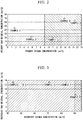
- concentration of oxygen and the concentration of the raw material in the gas mixture in the gasifier 6 are shown in FIG. 2 and Table 1.
- the molar concentration of oxygen in the gas mixture is referred to as a primary oxygen concentration
- the molar concentration of the raw material is referred to as a primary raw material concentration.
- the concentration of oxygen and the concentration of the raw material in the gas mixture in the gasifier 6 are the same as the concentration of oxygen and the concentration of the raw material in the gas mixture in the derivation end 19b (outlet) of the gasifier 6.
- FIG. 2 and Table 1 show that, in Example 1, the primary oxygen concentration exceeds 9%, and the primary raw material concentration is less than 24%, and thus the gas mixture is in the combustible range.
- the primary raw material concentration is less than 24%; however, the primary oxygen concentration is 9% or less, and thus the gas mixture does not combust.
- the primary oxygen concentration is 9% or less, and the primary raw material concentration is 24% or more, and thus the gas mixture does not combust.
- the primary oxygen concentration exceeds 9%; however, the primary raw material concentration is 24% or more, and thus the gas mixture does not combust.
- the gas mixture that has passed through the gasifier 6 is emitted from the raw material flow path 16a in the burner 7 through the main flow path 3 (the fourth flow path 3d) (refer to FIG. 1B ).
- an oxygen-containing gas is added to the gas mixture through the downstream addition flow path 9. Due to the addition of the oxygen-containing gas, the concentration of oxygen in the gas mixture increases.
- the oxygen-containing gas may be an oxygen (O 2 ) gas or a gas including oxygen (O 2 ) and the above-described carrier gas.
- the concentration of oxygen in the gas mixture in an outlet 7a (an outflow opening of the raw material flow path 16a) of the burner 7 is preferably lower than a concentration of oxygen necessary to completely combust the raw material (a concentration at which the oxygen adequacy ratio reaches 100%).
- the concentration of oxygen in the gas mixture is preferably, for example, a concentration corresponding to 30% to 40% of the concentration of oxygen necessary to completely combust the raw material.
- the concentration of oxygen in the gas mixture is set to be lower than the concentration of oxygen necessary to completely combust the raw material, it is possible to prevent easy occurrences of backfire.
- the ratio (the flow rate/the concentration of oxygen) of the flow rate (m/s) of the gas mixture to the molar concentration of oxygen (%) in the standard state (0°C, 1 atm) in the outlet 7a (the outflow opening of the raw material flow path 16a) of the burner 7 is preferably 3.0 m/s ⁇ % or less.
- the ratio (the flow rate/the concentration of oxygen) is set to 3.0 m/s ⁇ % or less, it is possible to prevent easy occurrences of backfire. Meanwhile, 1 atm is 1.01325 ⁇ 10 5 Pa.
- concentration of oxygen and the concentration of the raw material in the gas mixture in the outlet 7a (the outflow opening of the raw material flow path 16a) of the burner 7 are shown in FIG. 3 and Table 1.
- concentration of oxygen in the gas mixture is referred to as a secondary oxygen concentration
- concentration of the raw material is referred to as a secondary raw material concentration.
- FIG. 3 and Table 1 show that, in Examples 1 to 4, the secondary raw material concentration is in the combustible range; however, the secondary oxygen concentration is low, and thus the gas mixture does not combust.
- Example 5 the secondary oxygen concentration is high, and the secondary raw material concentration is also in the combustible range, and thus the gas mixture is combustible.
- the oxygen adequacy ratio reaches 100% or more. Meanwhile, regarding the concentration of oxygen in the emitted gas mixture, the oxygen adequacy ratio may reach 100% or more due to oxygen in the atmosphere.
- the gas mixture emitted from the raw material flow path 16a combusts together with the fuel gas emitted from the fuel flow path 16b, and the flame 17 generated in the outlet 7a of the burner 7 faces a soot deposit 18. Therefore, SiO 2 fine particles generated in the flame 17 are deposited on the surface of the soot deposit 18 and are subjected to a heating step, thereby obtaining a glass preform (glass ingot).
- oxygen (O 2 ) is added to the raw material compound 13 through the upstream addition flow path 8 and the downstream addition flow path 9. Therefore, the gas mixture including oxygen has been sufficiently mixed and homogenized at the time of being emitted from the burner 7, and an oxidation and combustion reaction of the raw material compound proceeds with no delay. Therefore, incomplete combustion does not easily occur even when the flow rate of the gas mixture is increased. Therefore, compared with manufacturing methods in which no oxygen is added, it is possible to increase the flow rate of the gas mixture and increase the production rate.
- the oxygen-containing gas is added to the gas mixture through the upstream addition flow path 8 so that the concentration of oxygen or the concentration of the raw material in the gas mixture is not in the combustible range in the derivation end (outlet) 19b of the gasifier 6. Therefore, even when the flow of the gas mixture stops and backfire (for example, combustion in the flow path) occurs for any reason, backfire does not reach the gasifier 6 or the upstream side of the gasifier. In addition, during the ordinary operation of the supply system 1, similarly, backfire does not reach the gasifier 6 or the upstream side of the gasifier.
- a glass ingot that is manufactured using the manufacturing method of the present embodiment can be applied to, for example, optical fiber preforms, lenses, optical glass, optical components, and the like.
Landscapes
- Chemical & Material Sciences (AREA)
- Engineering & Computer Science (AREA)
- Life Sciences & Earth Sciences (AREA)
- General Life Sciences & Earth Sciences (AREA)
- Geochemistry & Mineralogy (AREA)
- Manufacturing & Machinery (AREA)
- Materials Engineering (AREA)
- Organic Chemistry (AREA)
- Chemical Kinetics & Catalysis (AREA)
- General Chemical & Material Sciences (AREA)
- Glass Melting And Manufacturing (AREA)
- Manufacture, Treatment Of Glass Fibers (AREA)
Abstract
Description
- The present invention relates to a method for manufacturing a glass ingot.
- Priority is claimed on Japanese Patent Application No.
2016-083502, filed on April 19, 2016 - As a method for manufacturing a glass ingot such as a preform for an optical fiber, for example, there is a method in which a soot deposit is produced by depositing SiO2 fine particles and is heated, thereby obtaining a glass ingot (for example, refer to Patent Document 1).
- In the above-described manufacturing of a glass ingot, it is possible to use a manufacturing apparatus provided with a supply system having a burner that combusts a raw material gas and generates SiO2. In the step of depositing SiO2 fine particles (deposition step), a raw material gas including silicon is supplied to the burner, and SiO2 fine particles generated in flame that is generated in the outlet of the burner are deposited on a target.
- In the deposition step, when the flow rate of the raw material gas is increased, the amount of carbon soot in soot is likely to increase due to incomplete combustion, and thus it is not easy to increase the production rate. In order to obtain soot including no carbon, it is effective to add oxygen (O2) as a combustion-supporting gas to the raw material gas.
- [Patent Document 1] Japanese Patent No.
4158009 - In the above-described manufacturing method, oxygen (O2) is added to the raw material gas, and thus it is necessary to prevent occurrences of backfire in the supply system during the ordinary operation of the supply system and during the pause of the raw material gas flow.
- The present invention has been made in consideration of the above-described circumstance, and an object of the present invention is to provide a method for manufacturing a glass ingot which is capable of increasing the production rate and prevents occurrences of backfire in a supply system.
- According to a first aspect of the present invention, there is provided a method for manufacturing a glass ingot, including: preparing a supply system including a gasifier that gasifies a raw material compound including an organic silicon compound supplied from a supply source and a burner that combusts the gasified raw material compound and generate SiO2, adding an oxygen-containing gas to the raw material compound at a plurality of addition places including an upstream addition place located in the gasifier or on an upstream side of the gasifier and a downstream addition place located on a downstream side of the gasifier in which locations of the raw material compound in a flow direction are different in the supply system so as to form a raw material mixture, and adding the oxygen-containing gas at the upstream addition place so that a concentration of oxygen or a concentration of the raw material compound in the raw material mixture is not in a combustible range of the raw material mixture in an outlet of the gasifier.
- In the first aspect, a flow rate of the oxygen-containing gas to be added at the upstream addition place may be at least 3 slm, and, in the outlet of the gasifier, a molar concentration of oxygen in the raw material mixture may be 9% or less or a molar concentration of the raw material compound in the raw material mixture may be 24% or more.
- In the first aspect, at the downstream addition place, the oxygen-containing gas may be added so that a ratio of a flow rate of the raw material mixture to the molar concentration of oxygen in terms of a standard state in the outlet of the burner reaches 3.0 m/s·% or less.
- In the first aspect, the concentration of oxygen in the raw material mixture in the outlet of the burner may be lower than the concentration of oxygen necessary to completely combust the raw material compound.
- In the first aspect, the glass ingot may be an optical fiber preform.
- According to the above-described aspect of the present invention, oxygen (O2) is added to the raw material compound through an upstream addition flow path and a downstream addition flow path. Therefore, the raw material mixture including oxygen has been sufficiently mixed and homogenized at the time of being emitted from the burner, and an oxidation and combustion reaction of the raw material compound proceeds with no delay. Therefore, incomplete combustion does not easily occur even when the flow rate of the raw material mixture is increased. Therefore, compared with manufacturing methods in which no oxygen is added, it is possible to increase the flow rate of the raw material mixture and increase the production rate.
- According to the above-described aspect of the present invention, the amount of the oxygen-containing gas to be added through the upstream addition flow path is determined such that the concentration of oxygen or the concentration of the raw material in the raw material mixture is not in the combustible range in the outlet of the gasifier. Therefore, even when the flow of the raw material mixture stops and backfire (for example, combustion in the flow path) occurs due to any reasons, backfire does not reach the gasifier or the upstream side of the gasifier. In addition, during the ordinary operation of the supply system, similarly, backfire does not reach the gasifier or the upstream side of the gasifier.
-
-
FIG. 1A is a view schematically showing a supply system in a manufacturing apparatus that can be used in a method for manufacturing a glass ingot of an embodiment of the present invention. -
FIG. 1B is a view schematically showing a structure of a burner in the manufacturing apparatus ofFIG. 1A . -
FIG. 2 is a view showing examples of a primary oxygen concentration and a primary raw material concentration of a gas mixture in the embodiment of the present invention. -
FIG. 3 is a view showing examples of a secondary oxygen concentration and a secondary raw material concentration of the gas mixture in the embodiment of the present invention. - Hereinafter, an embodiment of the present invention will be described with reference to drawings.
-
FIG. 1A is a view schematically showing asupply system 1 in amanufacturing apparatus 10 that can be used in a method for manufacturing a glass preform (glass ingot) of a first embodiment of the present invention.FIG. 1B is a view schematically showing a structure of aburner 7 in themanufacturing apparatus 10. - As shown in
FIG. 1A , thesupply system 1 includes a liquid container 2 (supply source), amain flow path 3, adeaeration portion 4, amass flow controller 5, agasifier 6, aburner 7, a upstreamaddition flow path 8, a downstreamaddition flow path 9, and a fuelgas flow path 11. Theliquid container 2, themain flow path 3, thedeaeration portion 4, themass flow controller 5, thegasifier 6, and theburner 7 are arranged in this order from an upstream side toward a downstream side in a flow direction of araw material compound 13. - The
liquid container 2 is capable of storing the liquid-formraw material compound 13. Theliquid container 2 has an airtight structure, and aninner space 2a can be pressurized by introducing apressurization gas 15 thereinto through agas supply portion 14. Meanwhile, hereinafter, there will be cases in which the raw material compound is simply referred to as the raw material. - The
main flow path 3 is capable of leading theraw material compound 13 in theliquid container 2 to theburner 7 through thedeaeration portion 4, themass flow controller 5, and thegasifier 6. - The
main flow path 3 has afirst flow path 3a, asecond flow path 3b, athird flow path 3c, and afourth flow path 3d. Thefirst flow path 3a leads theraw material compound 13 in theliquid container 2 to thedeaeration portion 4. Thesecond flow path 3b leads theraw material compound 13 that has passed through thedeaeration portion 4 to themass flow controller 5. Thethird flow path 3c leads theraw material compound 13 that has passed through themass flow controller 5 to thegasifier 6. Thefourth flow path 3d leads theraw material compound 13 that has passed through thegasifier 6 to theburner 7. - The
deaeration portion 4 is capable of deaerating dissolved gas from theraw material compound 13 by depressurization or the like. - The
mass flow controller 5 is capable of controlling the flow rate of theraw material compound 13. - The
gasifier 6 is capable of gasifying the liquid-formraw material compound 13 by heating or the like. Thethird flow path 3c is connected to anintroduction end 19a which is one end portion of thegasifier 6. Thefourth flow path 3d is connected to aderivation end 19b which is the other end portion of thegasifier 6. - The
burner 7 has anozzle 16. As shown inFIG. 1B , thenozzle 16 has a rawmaterial flow path 16a and a plurality offuel flow paths 16b. In the rawmaterial flow path 16a, a gas mixture supplied from themain flow path 3 flows. In the plurality offuel flow paths 16b, a fuel gas supplied from the fuelgas flow path 11 flow. The rawmaterial flow path 16a and thefuel flow paths 16b are formed independently from each other. Thefuel flow paths 16b are located on, for example, an outer circumferential side of the rawmaterial flow path 16a. - The upstream
addition flow path 8 is connected to thegasifier 6 and is capable of adding an oxygen-containing gas to theraw material compound 13 in thegasifier 6. A place to which the upstreamaddition flow path 8 is connected is referred to as anupstream addition place 21. The oxygen-containing gas is a gas containing oxygen (O2). The upstreamaddition flow path 8 is preferably connected to an upstream-side portion 6a of thegasifier 6. The upstream-side portion 6a refers to a portion on the upstream side of the center in the flow direction of theraw material compound 13. A portion on the downstream side of thegasifier 6 in the flow direction of theraw material compound 13 is referred to as a downstream-side portion 6b. - Meanwhile, in the
manufacturing apparatus 10 shown inFIG. 1A , the upstreamaddition flow path 8 is connected to thegasifier 6; however, the connection place of the upstreamaddition flow path 8 may be thegasifier 6 or a place located on the upstream side of thegasifier 6. For example, the connection place of the upstreamaddition flow path 8 may be the downstream-side portion 6b of thegasifier 6 or may be thesecond flow path 3b, thethird flow path 3c, or the like. - In addition, the number of upstream addition flow paths is not limited to one and may be more than one. For example, a first upstream addition flow path may be connected to the
third flow path 3c, and a second upstream addition flow path may be connected to thegasifier 6. - The downstream
addition flow path 9 is connected to thefourth flow path 3d and is capable of adding an oxygen-containing gas to the gas mixture in thefourth flow path 3d. A place in which the downstreamaddition flow path 9 is connected to thefourth flow path 3d is referred to as adownstream addition place 22. - Meanwhile, in the
manufacturing apparatus 10 shown inFIG. 1A , the downstreamaddition flow path 9 is connected to thefourth flow path 3d; however, the connection place of the downstreamaddition flow path 9 may be a place located on the downstream side of thegasifier 6. For example, the connection place of the downstreamaddition flow path 9 may be theburner 7. - In addition, the number of downstream addition flow paths is not limited to one and may be more than one. For example, a first downstream addition flow path may be connected to the
fourth flow path 3d, and a second downstream addition flow path may be connected to theburner 7. - Next, a method for manufacturing a glass preform (glass ingot) of the present embodiment will be described using a case in which the
manufacturing apparatus 10 shown inFIG. 1A is used as an example. - Examples of the
raw material compound 13 that is stored in theliquid container 2 include organic silicon compounds such as alkylsilane, alkoxysilane, alkylsiloxane, and alkylcyclosiloxane. - Examples of alkylsilane include tetraalkylsilane.
- Examples of alkoxysilane include tetraalkoxysilane such as tetramethoxysilane; and alkylalkoysilane such as methyltrimethoxysilane.
- Examples of alkylsiloxane include hexamethyldisiloxane.
- Examples of alkylcyclosiloxane include hexamethylcyclotrisiloxane, tetramethylcyclotrisiloxane, octamethylcyclotetrasiloxane (OMCTS), and decamethylcyclopentasiloxane.
- Among these, OMCTS is particularly preferred. The
raw material compound 13 stored in theliquid container 2 is a liquid. - The
inner space 2a of theliquid container 2 is pressurized by introducing the pressurization gas 15 (for example, nitrogen (N2)) into theliquid container 2 through thegas supply portion 14. Therefore, theraw material compound 13 is derived from theliquid container 2 through the main flow path 3 (thefirst flow path 3a) and introduced into thedeaeration portion 4. - In the
deaeration portion 4, dissolved gas is deaerated from theraw material compound 13. - The
raw material compound 13 that has passed through thedeaeration portion 4 is introduced into themass flow controller 5 through the main flow path 3 (thesecond flow path 3b). After the flow rate of the raw material compound is controlled using themass flow controller 5, theraw material compound 13 is led to thegasifier 6 through the main flow path 3 (thethird flow path 3c). Theraw material compound 13 is gasified in thegasifier 6 by heating or the like. Hereinafter, there will be cases in which the gasifiedraw material compound 13 is referred to as a raw material gas. - In the
gasifier 6, an oxygen-containing gas including oxygen (O2) is added to theraw material compound 13 through the upstreamaddition flow path 8. Due to the addition of the oxygen-containing gas, theraw material compound 13 turns into a gas mixture including oxygen (O2) (raw material mixture). - The flow rate of the oxygen-containing gas to be added through the upstream
addition flow path 8 is preferably at least 3 slm. When the flow rate of the oxygen-containing gas is preferably at least 3 slm or more, it is possible to increase the flow rate of the gas mixture that is emitted from the rawmaterial flow path 16a in theburner 7. Therefore, it is possible to prevent easy occurrences of backfire. The backfire refers to the fact thatflame 17 from theburner 7 enters an inside of thesupply system 1 and combusts the raw material compound and refers to, for example, combustion in the flow path. - The oxygen-containing gas may be an oxygen (O2) gas or a gas mixture including oxygen (O2) and an additional gas. The additional gas is, for example, an inert gas such as Ar or nitrogen (N2), and this gas is capable of playing a role of a carrier gas and thus stabilizing the flow rate of the raw material gas.
- The amount of the oxygen-containing gas to be added through the upstream
addition flow path 8 is determined such that the concentration of oxygen or the concentration of the raw material in the gas mixture is not in a combustible range in thederivation end 19b (outlet) of thegasifier 6. The present inventors repeated studies regarding the combustion of the gas mixture and consequently found that, when the molar concentration of oxygen in the gas mixture is 9% or less or the molar concentration of the raw material (the molar concentration of the raw material compound) is 24% or more, the gas mixture is in the combustible range. - When the molar concentration of oxygen in the gas mixture is 9% or less, there is a lack of oxygen, and the gas mixture does not combust even in the case of coming into contact with a heat source. When the molar concentration of the raw material in the gas mixture is 24% or more, the concentration of the raw material is above the combustible range, and thus the gas mixture does not combust even in the case of coming into contact with a heat source. When the molar concentration of oxygen in the gas mixture is 9% or less or the molar concentration of the raw material is 24% or more, it is possible to prevent backfire. Meanwhile, the molar concentration at which OMCTS can be combusted is 0.5% to 24%.
- In order to increase the production rate of a glass preform (glass ingot) in the oxygen-containing gas to be added through the upstream
addition flow path 8, the concentration of the carrier gas (for example, Ar or nitrogen (N2)) is preferably low. Therefore, the concentration of oxygen (O2) in the oxygen-containing gas is desirably high to a certain extent. The concentration of oxygen (O2) in the oxygen-containing gas can be determined so that the molar concentration of oxygen in the gas mixture reaches, for example, 0.1% or more in thederivation end 19b (outlet) of thegasifier 6. Therefore, it is possible to stabilize the flow rate of the raw material gas, relatively increase the concentration of the raw material in the gas mixture, and improve the production rate. The molar concentration of the raw material in the gas mixture is preferably less than 85%. - Examples of the concentration of oxygen and the concentration of the raw material in the gas mixture in the
gasifier 6 are shown inFIG. 2 and Table 1. The molar concentration of oxygen in the gas mixture is referred to as a primary oxygen concentration, and the molar concentration of the raw material is referred to as a primary raw material concentration. Meanwhile, the concentration of oxygen and the concentration of the raw material in the gas mixture in thegasifier 6 are the same as the concentration of oxygen and the concentration of the raw material in the gas mixture in thederivation end 19b (outlet) of thegasifier 6.(Table 1) Primary oxygen concentration [mol%] Primary raw material concentration [mol%] Secondary oxygen concentration [mol%] Secondary raw material concentration [mol%] Possibility of flame backflow during backfire Example 1 11 20.5 44 13 Yes Example 2 5.8 21.7 44 13 No Example 3 1.7 44.3 71.1 13 No Example 4 13.8 69.0 83.7 13 No Example 5 16.3 63.3 90.2 7.4 Yes -
FIG. 2 and Table 1 show that, in Example 1, the primary oxygen concentration exceeds 9%, and the primary raw material concentration is less than 24%, and thus the gas mixture is in the combustible range. In Example 2, the primary raw material concentration is less than 24%; however, the primary oxygen concentration is 9% or less, and thus the gas mixture does not combust. In Example 3, the primary oxygen concentration is 9% or less, and the primary raw material concentration is 24% or more, and thus the gas mixture does not combust. In Examples 4 and 5, the primary oxygen concentration exceeds 9%; however, the primary raw material concentration is 24% or more, and thus the gas mixture does not combust. - The gas mixture that has passed through the
gasifier 6 is emitted from the rawmaterial flow path 16a in theburner 7 through the main flow path 3 (thefourth flow path 3d) (refer toFIG. 1B ). - In the
fourth flow path 3d, an oxygen-containing gas is added to the gas mixture through the downstreamaddition flow path 9. Due to the addition of the oxygen-containing gas, the concentration of oxygen in the gas mixture increases. The oxygen-containing gas may be an oxygen (O2) gas or a gas including oxygen (O2) and the above-described carrier gas. - The concentration of oxygen in the gas mixture in an
outlet 7a (an outflow opening of the rawmaterial flow path 16a) of theburner 7 is preferably lower than a concentration of oxygen necessary to completely combust the raw material (a concentration at which the oxygen adequacy ratio reaches 100%). The concentration of oxygen in the gas mixture is preferably, for example, a concentration corresponding to 30% to 40% of the concentration of oxygen necessary to completely combust the raw material. - When the concentration of oxygen in the gas mixture is set to be lower than the concentration of oxygen necessary to completely combust the raw material, it is possible to prevent easy occurrences of backfire.
- The ratio (the flow rate/the concentration of oxygen) of the flow rate (m/s) of the gas mixture to the molar concentration of oxygen (%) in the standard state (0°C, 1 atm) in the
outlet 7a (the outflow opening of the rawmaterial flow path 16a) of theburner 7 is preferably 3.0 m/s·% or less. When the ratio (the flow rate/the concentration of oxygen) is set to 3.0 m/s·% or less, it is possible to prevent easy occurrences of backfire.
Meanwhile, 1 atm is 1.01325×10⁵ Pa. - Examples of the concentration of oxygen and the concentration of the raw material in the gas mixture in the
outlet 7a (the outflow opening of the rawmaterial flow path 16a) of theburner 7 are shown inFIG. 3 and Table 1. The concentration of oxygen in the gas mixture is referred to as a secondary oxygen concentration, and the concentration of the raw material is referred to as a secondary raw material concentration. -
FIG. 3 and Table 1 show that, in Examples 1 to 4, the secondary raw material concentration is in the combustible range; however, the secondary oxygen concentration is low, and thus the gas mixture does not combust. In Example 5, the secondary oxygen concentration is high, and the secondary raw material concentration is also in the combustible range, and thus the gas mixture is combustible. - As shown in
FIG. 1B , to the gas mixture emitted from the outflow opening of the rawmaterial flow path 16a, a fuel gas including oxygen (O2) emitted from the outflow opening of thefuel flow path 16b is mixed. Therefore, the oxygen adequacy ratio reaches 100% or more. Meanwhile, regarding the concentration of oxygen in the emitted gas mixture, the oxygen adequacy ratio may reach 100% or more due to oxygen in the atmosphere. - As shown in
FIG. 1A , in theburner 7, the gas mixture emitted from the rawmaterial flow path 16a combusts together with the fuel gas emitted from thefuel flow path 16b, and theflame 17 generated in theoutlet 7a of theburner 7 faces asoot deposit 18. Therefore, SiO2 fine particles generated in theflame 17 are deposited on the surface of thesoot deposit 18 and are subjected to a heating step, thereby obtaining a glass preform (glass ingot). - In the manufacturing method of the present embodiment, oxygen (O2) is added to the
raw material compound 13 through the upstreamaddition flow path 8 and the downstreamaddition flow path 9. Therefore, the gas mixture including oxygen has been sufficiently mixed and homogenized at the time of being emitted from theburner 7, and an oxidation and combustion reaction of the raw material compound proceeds with no delay. Therefore, incomplete combustion does not easily occur even when the flow rate of the gas mixture is increased. Therefore, compared with manufacturing methods in which no oxygen is added, it is possible to increase the flow rate of the gas mixture and increase the production rate. - In the manufacturing method of the present embodiment, the oxygen-containing gas is added to the gas mixture through the upstream
addition flow path 8 so that the concentration of oxygen or the concentration of the raw material in the gas mixture is not in the combustible range in the derivation end (outlet) 19b of thegasifier 6. Therefore, even when the flow of the gas mixture stops and backfire (for example, combustion in the flow path) occurs for any reason, backfire does not reach thegasifier 6 or the upstream side of the gasifier. In addition, during the ordinary operation of thesupply system 1, similarly, backfire does not reach thegasifier 6 or the upstream side of the gasifier. - Hitherto, the preferred embodiment has been described; however, the embodiment is an example of the present invention, and addition, omission, and other modifications can be carried out within the scope of the present invention.
- A glass ingot that is manufactured using the manufacturing method of the present embodiment can be applied to, for example, optical fiber preforms, lenses, optical glass, optical components, and the like.
-
- 1: Supply System
- 2: Liquid Container (Supply Source)
- 6: Gasifier
- 7: Burner
- 7a: Outlet of Burner
- 19b: Derivation End (Outlet of Gasifier)
- 21: Upstream Addition Place
- 22: Downstream Addition Place
Claims (5)
- A method for manufacturing a glass ingot, the method comprising:preparing a supply system comprising a gasifier that gasifies a raw material compound comprising an organic silicon compound supplied from a supply source and a burner that combusts the gasified raw material compound to generates SiO2;adding an oxygen-containing gas to the raw material compound at a plurality of addition places comprising an upstream addition place located in the gasifier or on an upstream side of the gasifier and a downstream addition place located on a downstream side of the gasifier in which locations of the raw material compound in a flow direction are different in the supply system so as to form a raw material mixture; andadding the oxygen-containing gas at the upstream addition place so that a concentration of oxygen or a concentration of the raw material compound in the raw material mixture is not in a combustible range of the raw material mixture in an outlet of the gasifier.
- The method for manufacturing a glass ingot according to Claim 1,
wherein a flow rate of the oxygen-containing gas to be added at the upstream addition place is at least 3 slm, and, in the outlet of the gasifier, a molar concentration of oxygen in the raw material mixture is 9% or less or a molar concentration of the raw material compound in the raw material mixture is 24% or more. - The method for manufacturing a glass ingot according to Claim 1 or 2,
wherein, at the downstream addition place, the oxygen-containing gas is added so that a ratio of a flow rate of the raw material mixture to the molar concentration of oxygen in terms of a standard state in the outlet of the burner reaches 3.0 m/s·% or less. - The method for manufacturing a glass ingot according to any one of Claims 1 to 3,
wherein the concentration of oxygen in the raw material mixture in the outlet of the burner is lower than a concentration of oxygen necessary to completely combust the raw material compound. - The method for manufacturing a glass ingot according to any one of Claims 1 to 4,
wherein the glass ingot is an optical fiber preform.
Applications Claiming Priority (2)
| Application Number | Priority Date | Filing Date | Title |
|---|---|---|---|
| JP2016083502A JP6650820B2 (en) | 2016-04-19 | 2016-04-19 | Manufacturing method of glass ingot |
| PCT/JP2017/014079 WO2017183443A1 (en) | 2016-04-19 | 2017-04-04 | Method for manufacturing glass ingot |
Publications (3)
| Publication Number | Publication Date |
|---|---|
| EP3447033A1 true EP3447033A1 (en) | 2019-02-27 |
| EP3447033A4 EP3447033A4 (en) | 2019-12-11 |
| EP3447033B1 EP3447033B1 (en) | 2022-05-04 |
Family
ID=60115817
Family Applications (1)
| Application Number | Title | Priority Date | Filing Date |
|---|---|---|---|
| EP17785785.1A Active EP3447033B1 (en) | 2016-04-19 | 2017-04-04 | Method for manufacturing glass ingot |
Country Status (5)
| Country | Link |
|---|---|
| US (1) | US10836671B2 (en) |
| EP (1) | EP3447033B1 (en) |
| JP (1) | JP6650820B2 (en) |
| CN (1) | CN108713003B (en) |
| WO (1) | WO2017183443A1 (en) |
Families Citing this family (4)
| Publication number | Priority date | Publication date | Assignee | Title |
|---|---|---|---|---|
| EP4015466A1 (en) | 2020-12-16 | 2022-06-22 | Heraeus Quarzglas GmbH & Co. KG | Method for the manufacture of synthetic quartz glass |
| EP4015468A1 (en) | 2020-12-16 | 2022-06-22 | Heraeus Quarzglas GmbH & Co. KG | Method for the manufacture of synthetic quartz glass |
| EP4015467A1 (en) | 2020-12-16 | 2022-06-22 | Heraeus Quarzglas GmbH & Co. KG | Method for the manufacture of synthetic quartz glass |
| JP7652585B2 (en) * | 2021-02-22 | 2025-03-27 | 株式会社フジクラ | Manufacturing method of optical fiber preform and manufacturing method of optical fiber |
Family Cites Families (9)
| Publication number | Priority date | Publication date | Assignee | Title |
|---|---|---|---|---|
| US5632797A (en) * | 1994-12-30 | 1997-05-27 | Corning Incorporated | Method of providing vaporized halide-free, silicon-containing compounds |
| US5558687A (en) | 1994-12-30 | 1996-09-24 | Corning Incorporated | Vertical, packed-bed, film evaporator for halide-free, silicon-containing compounds |
| US5599371A (en) | 1994-12-30 | 1997-02-04 | Corning Incorporated | Method of using precision burners for oxidizing halide-free, silicon-containing compounds |
| JP4158009B2 (en) | 2001-12-11 | 2008-10-01 | 信越化学工業株式会社 | Synthetic quartz glass ingot and method for producing synthetic quartz glass |
| JP2003226544A (en) * | 2002-02-01 | 2003-08-12 | Fujikura Ltd | Method for producing porous optical fiber preform |
| JP2012162414A (en) * | 2011-02-04 | 2012-08-30 | Sumitomo Electric Ind Ltd | Method and apparatus for producing glass fine particle deposit |
| DE102011121153B3 (en) * | 2011-12-15 | 2013-03-21 | Heraeus Quarzglas Gmbh & Co. Kg | Process for the production of synthetic quartz glass and quartz glass for use as cladding material of an optical fiber |
| EP3059212A1 (en) * | 2015-02-18 | 2016-08-24 | Heraeus Quarzglas GmbH & Co. KG | Method and apparatus for making silica glass from polymerisable polyalkylsiloxane with membrane filter as cleaning device |
| JP2017036172A (en) | 2015-08-07 | 2017-02-16 | 株式会社フジクラ | Manufacturing method for optical fiber preform |
-
2016
- 2016-04-19 JP JP2016083502A patent/JP6650820B2/en active Active
-
2017
- 2017-04-04 WO PCT/JP2017/014079 patent/WO2017183443A1/en not_active Ceased
- 2017-04-04 EP EP17785785.1A patent/EP3447033B1/en active Active
- 2017-04-04 US US16/080,632 patent/US10836671B2/en active Active
- 2017-04-04 CN CN201780015383.1A patent/CN108713003B/en active Active
Also Published As
| Publication number | Publication date |
|---|---|
| JP6650820B2 (en) | 2020-02-19 |
| CN108713003A (en) | 2018-10-26 |
| US10836671B2 (en) | 2020-11-17 |
| EP3447033B1 (en) | 2022-05-04 |
| JP2017193456A (en) | 2017-10-26 |
| WO2017183443A1 (en) | 2017-10-26 |
| CN108713003B (en) | 2021-07-23 |
| EP3447033A4 (en) | 2019-12-11 |
| US20190084866A1 (en) | 2019-03-21 |
Similar Documents
| Publication | Publication Date | Title |
|---|---|---|
| EP3447033B1 (en) | Method for manufacturing glass ingot | |
| EP3450407B1 (en) | Method for manufacturing glass matrix | |
| US10399888B2 (en) | Method for producing glass particulate deposit and method for producing glass preform | |
| US9695080B2 (en) | Glass particle deposit producing method and glass preform producing method | |
| JP2017036172A (en) | Manufacturing method for optical fiber preform | |
| JP7276335B2 (en) | Manufacturing method of glass fine particle deposit | |
| JP2020200225A (en) | Apparatus and method for manufacturing optical fiber porous glass preform | |
| US9676657B2 (en) | Method for producing glass particulate deposit and method for producing glass preform | |
| US20190241458A1 (en) | Method for manufacturing porous glass fine particle body, manufacturing apparatus for porous glass fine particle body, and method for manufacturing glass preform | |
| US20220033294A1 (en) | Method for manufacturing glass fine particle deposit and method for manufacturing glass base material | |
| US11667557B2 (en) | Apparatus and method for producing porous glass preform | |
| JPH04502957A (en) | Method and apparatus for combustion of oxygen-free toxic gas effluents | |
| JP5930557B2 (en) | Method and apparatus for mixing vaporized precursors and gases to produce silica glass | |
| JP2018193279A (en) | Method for manufacturing glass fine particle deposit, method for manufacturing glass preform and glass fine particle deposit | |
| JP6643395B2 (en) | Method and apparatus for producing porous glass microparticles | |
| US6378337B1 (en) | Method for producing bulk fused silica | |
| JP4460062B2 (en) | Optical fiber preform manufacturing method | |
| JP2000281358A (en) | Method and apparatus for producing synthetic quartz glass and synthetic quartz glass | |
| US20210163337A1 (en) | Method for producing porous glass fine particle body and method for producing optical fiber preform | |
| CN121342322B (en) | Device and method for preparing porous opaque high-purity quartz by CVD (chemical vapor deposition) method | |
| JP7652585B2 (en) | Manufacturing method of optical fiber preform and manufacturing method of optical fiber | |
| JP7404144B2 (en) | Method for manufacturing porous glass particles and method for manufacturing optical fiber base material | |
| JP2022070166A (en) | Porous glass base material manufacturing equipment and manufacturing method | |
| JP2006117469A (en) | Method and apparatus for producing synthetic quartz glass |
Legal Events
| Date | Code | Title | Description |
|---|---|---|---|
| STAA | Information on the status of an ep patent application or granted ep patent |
Free format text: STATUS: THE INTERNATIONAL PUBLICATION HAS BEEN MADE |
|
| PUAI | Public reference made under article 153(3) epc to a published international application that has entered the european phase |
Free format text: ORIGINAL CODE: 0009012 |
|
| STAA | Information on the status of an ep patent application or granted ep patent |
Free format text: STATUS: REQUEST FOR EXAMINATION WAS MADE |
|
| 17P | Request for examination filed |
Effective date: 20180820 |
|
| AK | Designated contracting states |
Kind code of ref document: A1 Designated state(s): AL AT BE BG CH CY CZ DE DK EE ES FI FR GB GR HR HU IE IS IT LI LT LU LV MC MK MT NL NO PL PT RO RS SE SI SK SM TR |
|
| AX | Request for extension of the european patent |
Extension state: BA ME |
|
| DAV | Request for validation of the european patent (deleted) | ||
| DAX | Request for extension of the european patent (deleted) | ||
| A4 | Supplementary search report drawn up and despatched |
Effective date: 20191108 |
|
| RIC1 | Information provided on ipc code assigned before grant |
Ipc: C03B 8/04 20060101AFI20191104BHEP Ipc: C03B 37/018 20060101ALI20191104BHEP Ipc: C03B 37/014 20060101ALI20191104BHEP |
|
| STAA | Information on the status of an ep patent application or granted ep patent |
Free format text: STATUS: EXAMINATION IS IN PROGRESS |
|
| 17Q | First examination report despatched |
Effective date: 20200420 |
|
| GRAP | Despatch of communication of intention to grant a patent |
Free format text: ORIGINAL CODE: EPIDOSNIGR1 |
|
| STAA | Information on the status of an ep patent application or granted ep patent |
Free format text: STATUS: GRANT OF PATENT IS INTENDED |
|
| INTG | Intention to grant announced |
Effective date: 20211221 |
|
| GRAS | Grant fee paid |
Free format text: ORIGINAL CODE: EPIDOSNIGR3 |
|
| GRAA | (expected) grant |
Free format text: ORIGINAL CODE: 0009210 |
|
| STAA | Information on the status of an ep patent application or granted ep patent |
Free format text: STATUS: THE PATENT HAS BEEN GRANTED |
|
| RIN1 | Information on inventor provided before grant (corrected) |
Inventor name: OOZEKI, NOBUO |
|
| AK | Designated contracting states |
Kind code of ref document: B1 Designated state(s): AL AT BE BG CH CY CZ DE DK EE ES FI FR GB GR HR HU IE IS IT LI LT LU LV MC MK MT NL NO PL PT RO RS SE SI SK SM TR |
|
| REG | Reference to a national code |
Ref country code: GB Ref legal event code: FG4D |
|
| REG | Reference to a national code |
Ref country code: CH Ref legal event code: EP |
|
| REG | Reference to a national code |
Ref country code: AT Ref legal event code: REF Ref document number: 1488905 Country of ref document: AT Kind code of ref document: T Effective date: 20220515 |
|
| REG | Reference to a national code |
Ref country code: IE Ref legal event code: FG4D Ref country code: DE Ref legal event code: R096 Ref document number: 602017056987 Country of ref document: DE |
|
| REG | Reference to a national code |
Ref country code: LT Ref legal event code: MG9D |
|
| REG | Reference to a national code |
Ref country code: NL Ref legal event code: MP Effective date: 20220504 |
|
| REG | Reference to a national code |
Ref country code: AT Ref legal event code: MK05 Ref document number: 1488905 Country of ref document: AT Kind code of ref document: T Effective date: 20220504 |
|
| PG25 | Lapsed in a contracting state [announced via postgrant information from national office to epo] |
Ref country code: SE Free format text: LAPSE BECAUSE OF FAILURE TO SUBMIT A TRANSLATION OF THE DESCRIPTION OR TO PAY THE FEE WITHIN THE PRESCRIBED TIME-LIMIT Effective date: 20220504 Ref country code: PT Free format text: LAPSE BECAUSE OF FAILURE TO SUBMIT A TRANSLATION OF THE DESCRIPTION OR TO PAY THE FEE WITHIN THE PRESCRIBED TIME-LIMIT Effective date: 20220905 Ref country code: NO Free format text: LAPSE BECAUSE OF FAILURE TO SUBMIT A TRANSLATION OF THE DESCRIPTION OR TO PAY THE FEE WITHIN THE PRESCRIBED TIME-LIMIT Effective date: 20220804 Ref country code: NL Free format text: LAPSE BECAUSE OF FAILURE TO SUBMIT A TRANSLATION OF THE DESCRIPTION OR TO PAY THE FEE WITHIN THE PRESCRIBED TIME-LIMIT Effective date: 20220504 Ref country code: LT Free format text: LAPSE BECAUSE OF FAILURE TO SUBMIT A TRANSLATION OF THE DESCRIPTION OR TO PAY THE FEE WITHIN THE PRESCRIBED TIME-LIMIT Effective date: 20220504 Ref country code: HR Free format text: LAPSE BECAUSE OF FAILURE TO SUBMIT A TRANSLATION OF THE DESCRIPTION OR TO PAY THE FEE WITHIN THE PRESCRIBED TIME-LIMIT Effective date: 20220504 Ref country code: GR Free format text: LAPSE BECAUSE OF FAILURE TO SUBMIT A TRANSLATION OF THE DESCRIPTION OR TO PAY THE FEE WITHIN THE PRESCRIBED TIME-LIMIT Effective date: 20220805 Ref country code: FI Free format text: LAPSE BECAUSE OF FAILURE TO SUBMIT A TRANSLATION OF THE DESCRIPTION OR TO PAY THE FEE WITHIN THE PRESCRIBED TIME-LIMIT Effective date: 20220504 Ref country code: ES Free format text: LAPSE BECAUSE OF FAILURE TO SUBMIT A TRANSLATION OF THE DESCRIPTION OR TO PAY THE FEE WITHIN THE PRESCRIBED TIME-LIMIT Effective date: 20220504 Ref country code: BG Free format text: LAPSE BECAUSE OF FAILURE TO SUBMIT A TRANSLATION OF THE DESCRIPTION OR TO PAY THE FEE WITHIN THE PRESCRIBED TIME-LIMIT Effective date: 20220804 Ref country code: AT Free format text: LAPSE BECAUSE OF FAILURE TO SUBMIT A TRANSLATION OF THE DESCRIPTION OR TO PAY THE FEE WITHIN THE PRESCRIBED TIME-LIMIT Effective date: 20220504 |
|
| PG25 | Lapsed in a contracting state [announced via postgrant information from national office to epo] |
Ref country code: RS Free format text: LAPSE BECAUSE OF FAILURE TO SUBMIT A TRANSLATION OF THE DESCRIPTION OR TO PAY THE FEE WITHIN THE PRESCRIBED TIME-LIMIT Effective date: 20220504 Ref country code: PL Free format text: LAPSE BECAUSE OF FAILURE TO SUBMIT A TRANSLATION OF THE DESCRIPTION OR TO PAY THE FEE WITHIN THE PRESCRIBED TIME-LIMIT Effective date: 20220504 Ref country code: LV Free format text: LAPSE BECAUSE OF FAILURE TO SUBMIT A TRANSLATION OF THE DESCRIPTION OR TO PAY THE FEE WITHIN THE PRESCRIBED TIME-LIMIT Effective date: 20220504 Ref country code: IS Free format text: LAPSE BECAUSE OF FAILURE TO SUBMIT A TRANSLATION OF THE DESCRIPTION OR TO PAY THE FEE WITHIN THE PRESCRIBED TIME-LIMIT Effective date: 20220904 |
|
| PG25 | Lapsed in a contracting state [announced via postgrant information from national office to epo] |
Ref country code: SM Free format text: LAPSE BECAUSE OF FAILURE TO SUBMIT A TRANSLATION OF THE DESCRIPTION OR TO PAY THE FEE WITHIN THE PRESCRIBED TIME-LIMIT Effective date: 20220504 Ref country code: SK Free format text: LAPSE BECAUSE OF FAILURE TO SUBMIT A TRANSLATION OF THE DESCRIPTION OR TO PAY THE FEE WITHIN THE PRESCRIBED TIME-LIMIT Effective date: 20220504 Ref country code: RO Free format text: LAPSE BECAUSE OF FAILURE TO SUBMIT A TRANSLATION OF THE DESCRIPTION OR TO PAY THE FEE WITHIN THE PRESCRIBED TIME-LIMIT Effective date: 20220504 Ref country code: EE Free format text: LAPSE BECAUSE OF FAILURE TO SUBMIT A TRANSLATION OF THE DESCRIPTION OR TO PAY THE FEE WITHIN THE PRESCRIBED TIME-LIMIT Effective date: 20220504 Ref country code: DK Free format text: LAPSE BECAUSE OF FAILURE TO SUBMIT A TRANSLATION OF THE DESCRIPTION OR TO PAY THE FEE WITHIN THE PRESCRIBED TIME-LIMIT Effective date: 20220504 Ref country code: CZ Free format text: LAPSE BECAUSE OF FAILURE TO SUBMIT A TRANSLATION OF THE DESCRIPTION OR TO PAY THE FEE WITHIN THE PRESCRIBED TIME-LIMIT Effective date: 20220504 |
|
| REG | Reference to a national code |
Ref country code: DE Ref legal event code: R097 Ref document number: 602017056987 Country of ref document: DE |
|
| PLBE | No opposition filed within time limit |
Free format text: ORIGINAL CODE: 0009261 |
|
| STAA | Information on the status of an ep patent application or granted ep patent |
Free format text: STATUS: NO OPPOSITION FILED WITHIN TIME LIMIT |
|
| PG25 | Lapsed in a contracting state [announced via postgrant information from national office to epo] |
Ref country code: AL Free format text: LAPSE BECAUSE OF FAILURE TO SUBMIT A TRANSLATION OF THE DESCRIPTION OR TO PAY THE FEE WITHIN THE PRESCRIBED TIME-LIMIT Effective date: 20220504 |
|
| 26N | No opposition filed |
Effective date: 20230207 |
|
| PG25 | Lapsed in a contracting state [announced via postgrant information from national office to epo] |
Ref country code: SI Free format text: LAPSE BECAUSE OF FAILURE TO SUBMIT A TRANSLATION OF THE DESCRIPTION OR TO PAY THE FEE WITHIN THE PRESCRIBED TIME-LIMIT Effective date: 20220504 |
|
| REG | Reference to a national code |
Ref country code: CH Ref legal event code: PL |
|
| GBPC | Gb: european patent ceased through non-payment of renewal fee |
Effective date: 20230404 |
|
| PG25 | Lapsed in a contracting state [announced via postgrant information from national office to epo] |
Ref country code: LU Free format text: LAPSE BECAUSE OF NON-PAYMENT OF DUE FEES Effective date: 20230404 |
|
| REG | Reference to a national code |
Ref country code: BE Ref legal event code: MM Effective date: 20230430 |
|
| PG25 | Lapsed in a contracting state [announced via postgrant information from national office to epo] |
Ref country code: MC Free format text: LAPSE BECAUSE OF FAILURE TO SUBMIT A TRANSLATION OF THE DESCRIPTION OR TO PAY THE FEE WITHIN THE PRESCRIBED TIME-LIMIT Effective date: 20220504 |
|
| PG25 | Lapsed in a contracting state [announced via postgrant information from national office to epo] |
Ref country code: GB Free format text: LAPSE BECAUSE OF NON-PAYMENT OF DUE FEES Effective date: 20230404 |
|
| PG25 | Lapsed in a contracting state [announced via postgrant information from national office to epo] |
Ref country code: MC Free format text: LAPSE BECAUSE OF FAILURE TO SUBMIT A TRANSLATION OF THE DESCRIPTION OR TO PAY THE FEE WITHIN THE PRESCRIBED TIME-LIMIT Effective date: 20220504 Ref country code: LI Free format text: LAPSE BECAUSE OF NON-PAYMENT OF DUE FEES Effective date: 20230430 Ref country code: IT Free format text: LAPSE BECAUSE OF FAILURE TO SUBMIT A TRANSLATION OF THE DESCRIPTION OR TO PAY THE FEE WITHIN THE PRESCRIBED TIME-LIMIT Effective date: 20220504 Ref country code: GB Free format text: LAPSE BECAUSE OF NON-PAYMENT OF DUE FEES Effective date: 20230404 Ref country code: FR Free format text: LAPSE BECAUSE OF NON-PAYMENT OF DUE FEES Effective date: 20230430 Ref country code: CH Free format text: LAPSE BECAUSE OF NON-PAYMENT OF DUE FEES Effective date: 20230430 |
|
| REG | Reference to a national code |
Ref country code: IE Ref legal event code: MM4A |
|
| PG25 | Lapsed in a contracting state [announced via postgrant information from national office to epo] |
Ref country code: BE Free format text: LAPSE BECAUSE OF NON-PAYMENT OF DUE FEES Effective date: 20230430 |
|
| PG25 | Lapsed in a contracting state [announced via postgrant information from national office to epo] |
Ref country code: IE Free format text: LAPSE BECAUSE OF NON-PAYMENT OF DUE FEES Effective date: 20230404 |
|
| PG25 | Lapsed in a contracting state [announced via postgrant information from national office to epo] |
Ref country code: IE Free format text: LAPSE BECAUSE OF NON-PAYMENT OF DUE FEES Effective date: 20230404 |
|
| PG25 | Lapsed in a contracting state [announced via postgrant information from national office to epo] |
Ref country code: BG Free format text: LAPSE BECAUSE OF FAILURE TO SUBMIT A TRANSLATION OF THE DESCRIPTION OR TO PAY THE FEE WITHIN THE PRESCRIBED TIME-LIMIT Effective date: 20220504 |
|
| PG25 | Lapsed in a contracting state [announced via postgrant information from national office to epo] |
Ref country code: BG Free format text: LAPSE BECAUSE OF FAILURE TO SUBMIT A TRANSLATION OF THE DESCRIPTION OR TO PAY THE FEE WITHIN THE PRESCRIBED TIME-LIMIT Effective date: 20220504 |
|
| REG | Reference to a national code |
Ref country code: DE Ref legal event code: R082 Ref document number: 602017056987 Country of ref document: DE Representative=s name: PLASSERAUD IP GMBH, DE |
|
| PGFP | Annual fee paid to national office [announced via postgrant information from national office to epo] |
Ref country code: DE Payment date: 20250305 Year of fee payment: 9 |
|
| PG25 | Lapsed in a contracting state [announced via postgrant information from national office to epo] |
Ref country code: CY Free format text: LAPSE BECAUSE OF FAILURE TO SUBMIT A TRANSLATION OF THE DESCRIPTION OR TO PAY THE FEE WITHIN THE PRESCRIBED TIME-LIMIT; INVALID AB INITIO Effective date: 20170404 |
|
| PG25 | Lapsed in a contracting state [announced via postgrant information from national office to epo] |
Ref country code: HU Free format text: LAPSE BECAUSE OF FAILURE TO SUBMIT A TRANSLATION OF THE DESCRIPTION OR TO PAY THE FEE WITHIN THE PRESCRIBED TIME-LIMIT; INVALID AB INITIO Effective date: 20170404 |
|
| PG25 | Lapsed in a contracting state [announced via postgrant information from national office to epo] |
Ref country code: TR Free format text: LAPSE BECAUSE OF FAILURE TO SUBMIT A TRANSLATION OF THE DESCRIPTION OR TO PAY THE FEE WITHIN THE PRESCRIBED TIME-LIMIT Effective date: 20220504 |