EP3446919B1 - Foldable manual child safety seat - Google Patents
Foldable manual child safety seat Download PDFInfo
- Publication number
- EP3446919B1 EP3446919B1 EP16754162.2A EP16754162A EP3446919B1 EP 3446919 B1 EP3446919 B1 EP 3446919B1 EP 16754162 A EP16754162 A EP 16754162A EP 3446919 B1 EP3446919 B1 EP 3446919B1
- Authority
- EP
- European Patent Office
- Prior art keywords
- support frame
- frame
- relative
- side face
- adjusting plate
- Prior art date
- Legal status (The legal status is an assumption and is not a legal conclusion. Google has not performed a legal analysis and makes no representation as to the accuracy of the status listed.)
- Active
Links
Images




Classifications
-
- B—PERFORMING OPERATIONS; TRANSPORTING
- B60—VEHICLES IN GENERAL
- B60N—SEATS SPECIALLY ADAPTED FOR VEHICLES; VEHICLE PASSENGER ACCOMMODATION NOT OTHERWISE PROVIDED FOR
- B60N2/00—Seats specially adapted for vehicles; Arrangement or mounting of seats in vehicles
- B60N2/24—Seats specially adapted for vehicles; Arrangement or mounting of seats in vehicles for particular purposes or particular vehicles
- B60N2/30—Non-dismountable or dismountable seats storable in a non-use position, e.g. foldable spare seats
- B60N2/3002—Non-dismountable or dismountable seats storable in a non-use position, e.g. foldable spare seats back-rest movements
- B60N2/3004—Non-dismountable or dismountable seats storable in a non-use position, e.g. foldable spare seats back-rest movements by rotation only
- B60N2/3009—Non-dismountable or dismountable seats storable in a non-use position, e.g. foldable spare seats back-rest movements by rotation only about transversal axis
- B60N2/3011—Non-dismountable or dismountable seats storable in a non-use position, e.g. foldable spare seats back-rest movements by rotation only about transversal axis the back-rest being hinged on the cushion, e.g. "portefeuille movement"
-
- B—PERFORMING OPERATIONS; TRANSPORTING
- B60—VEHICLES IN GENERAL
- B60N—SEATS SPECIALLY ADAPTED FOR VEHICLES; VEHICLE PASSENGER ACCOMMODATION NOT OTHERWISE PROVIDED FOR
- B60N2/00—Seats specially adapted for vehicles; Arrangement or mounting of seats in vehicles
- B60N2/02—Seats specially adapted for vehicles; Arrangement or mounting of seats in vehicles the seat or part thereof being movable, e.g. adjustable
- B60N2/22—Seats specially adapted for vehicles; Arrangement or mounting of seats in vehicles the seat or part thereof being movable, e.g. adjustable the back-rest being adjustable
- B60N2/2213—Gear wheel driven mechanism
-
- B—PERFORMING OPERATIONS; TRANSPORTING
- B60—VEHICLES IN GENERAL
- B60N—SEATS SPECIALLY ADAPTED FOR VEHICLES; VEHICLE PASSENGER ACCOMMODATION NOT OTHERWISE PROVIDED FOR
- B60N2/00—Seats specially adapted for vehicles; Arrangement or mounting of seats in vehicles
- B60N2/02—Seats specially adapted for vehicles; Arrangement or mounting of seats in vehicles the seat or part thereof being movable, e.g. adjustable
- B60N2/22—Seats specially adapted for vehicles; Arrangement or mounting of seats in vehicles the seat or part thereof being movable, e.g. adjustable the back-rest being adjustable
- B60N2/2222—Seats specially adapted for vehicles; Arrangement or mounting of seats in vehicles the seat or part thereof being movable, e.g. adjustable the back-rest being adjustable the back-rest having two or more parts
-
- B—PERFORMING OPERATIONS; TRANSPORTING
- B60—VEHICLES IN GENERAL
- B60N—SEATS SPECIALLY ADAPTED FOR VEHICLES; VEHICLE PASSENGER ACCOMMODATION NOT OTHERWISE PROVIDED FOR
- B60N2/00—Seats specially adapted for vehicles; Arrangement or mounting of seats in vehicles
- B60N2/02—Seats specially adapted for vehicles; Arrangement or mounting of seats in vehicles the seat or part thereof being movable, e.g. adjustable
- B60N2/22—Seats specially adapted for vehicles; Arrangement or mounting of seats in vehicles the seat or part thereof being movable, e.g. adjustable the back-rest being adjustable
- B60N2/225—Seats specially adapted for vehicles; Arrangement or mounting of seats in vehicles the seat or part thereof being movable, e.g. adjustable the back-rest being adjustable by cycloidal or planetary mechanisms
- B60N2/2251—Seats specially adapted for vehicles; Arrangement or mounting of seats in vehicles the seat or part thereof being movable, e.g. adjustable the back-rest being adjustable by cycloidal or planetary mechanisms with gears having orbital motion, e.g. sun and planet gears
-
- B—PERFORMING OPERATIONS; TRANSPORTING
- B60—VEHICLES IN GENERAL
- B60N—SEATS SPECIALLY ADAPTED FOR VEHICLES; VEHICLE PASSENGER ACCOMMODATION NOT OTHERWISE PROVIDED FOR
- B60N2/00—Seats specially adapted for vehicles; Arrangement or mounting of seats in vehicles
- B60N2/02—Seats specially adapted for vehicles; Arrangement or mounting of seats in vehicles the seat or part thereof being movable, e.g. adjustable
- B60N2/22—Seats specially adapted for vehicles; Arrangement or mounting of seats in vehicles the seat or part thereof being movable, e.g. adjustable the back-rest being adjustable
- B60N2/235—Seats specially adapted for vehicles; Arrangement or mounting of seats in vehicles the seat or part thereof being movable, e.g. adjustable the back-rest being adjustable by gear-pawl type mechanisms
- B60N2/2352—Seats specially adapted for vehicles; Arrangement or mounting of seats in vehicles the seat or part thereof being movable, e.g. adjustable the back-rest being adjustable by gear-pawl type mechanisms with external pawls
-
- B—PERFORMING OPERATIONS; TRANSPORTING
- B60—VEHICLES IN GENERAL
- B60N—SEATS SPECIALLY ADAPTED FOR VEHICLES; VEHICLE PASSENGER ACCOMMODATION NOT OTHERWISE PROVIDED FOR
- B60N2/00—Seats specially adapted for vehicles; Arrangement or mounting of seats in vehicles
- B60N2/24—Seats specially adapted for vehicles; Arrangement or mounting of seats in vehicles for particular purposes or particular vehicles
- B60N2/26—Seats specially adapted for vehicles; Arrangement or mounting of seats in vehicles for particular purposes or particular vehicles for children
- B60N2/28—Seats readily mountable on, and dismountable from, existing seats or other parts of the vehicle
-
- B—PERFORMING OPERATIONS; TRANSPORTING
- B60—VEHICLES IN GENERAL
- B60N—SEATS SPECIALLY ADAPTED FOR VEHICLES; VEHICLE PASSENGER ACCOMMODATION NOT OTHERWISE PROVIDED FOR
- B60N2/00—Seats specially adapted for vehicles; Arrangement or mounting of seats in vehicles
- B60N2/24—Seats specially adapted for vehicles; Arrangement or mounting of seats in vehicles for particular purposes or particular vehicles
- B60N2/30—Non-dismountable or dismountable seats storable in a non-use position, e.g. foldable spare seats
- B60N2/3002—Non-dismountable or dismountable seats storable in a non-use position, e.g. foldable spare seats back-rest movements
- B60N2/3004—Non-dismountable or dismountable seats storable in a non-use position, e.g. foldable spare seats back-rest movements by rotation only
- B60N2/3009—Non-dismountable or dismountable seats storable in a non-use position, e.g. foldable spare seats back-rest movements by rotation only about transversal axis
-
- B—PERFORMING OPERATIONS; TRANSPORTING
- B60—VEHICLES IN GENERAL
- B60N—SEATS SPECIALLY ADAPTED FOR VEHICLES; VEHICLE PASSENGER ACCOMMODATION NOT OTHERWISE PROVIDED FOR
- B60N2/00—Seats specially adapted for vehicles; Arrangement or mounting of seats in vehicles
- B60N2/24—Seats specially adapted for vehicles; Arrangement or mounting of seats in vehicles for particular purposes or particular vehicles
- B60N2/30—Non-dismountable or dismountable seats storable in a non-use position, e.g. foldable spare seats
- B60N2/3038—Cushion movements
- B60N2/3054—Cushion movements by translation only
- B60N2/3056—Cushion movements by translation only along longitunal axis
-
- B—PERFORMING OPERATIONS; TRANSPORTING
- B60—VEHICLES IN GENERAL
- B60N—SEATS SPECIALLY ADAPTED FOR VEHICLES; VEHICLE PASSENGER ACCOMMODATION NOT OTHERWISE PROVIDED FOR
- B60N2/00—Seats specially adapted for vehicles; Arrangement or mounting of seats in vehicles
- B60N2/24—Seats specially adapted for vehicles; Arrangement or mounting of seats in vehicles for particular purposes or particular vehicles
- B60N2/30—Non-dismountable or dismountable seats storable in a non-use position, e.g. foldable spare seats
- B60N2/3088—Non-dismountable or dismountable seats storable in a non-use position, e.g. foldable spare seats characterised by the mechanical link
- B60N2/3093—Non-dismountable or dismountable seats storable in a non-use position, e.g. foldable spare seats characterised by the mechanical link slides
-
- B—PERFORMING OPERATIONS; TRANSPORTING
- B60—VEHICLES IN GENERAL
- B60N—SEATS SPECIALLY ADAPTED FOR VEHICLES; VEHICLE PASSENGER ACCOMMODATION NOT OTHERWISE PROVIDED FOR
- B60N2/00—Seats specially adapted for vehicles; Arrangement or mounting of seats in vehicles
- B60N2/24—Seats specially adapted for vehicles; Arrangement or mounting of seats in vehicles for particular purposes or particular vehicles
- B60N2/30—Non-dismountable or dismountable seats storable in a non-use position, e.g. foldable spare seats
- B60N2/3097—Dismountable seats storable in a non-use position
-
- B—PERFORMING OPERATIONS; TRANSPORTING
- B60—VEHICLES IN GENERAL
- B60N—SEATS SPECIALLY ADAPTED FOR VEHICLES; VEHICLE PASSENGER ACCOMMODATION NOT OTHERWISE PROVIDED FOR
- B60N2/00—Seats specially adapted for vehicles; Arrangement or mounting of seats in vehicles
- B60N2/68—Seat frames
-
- B—PERFORMING OPERATIONS; TRANSPORTING
- B60—VEHICLES IN GENERAL
- B60N—SEATS SPECIALLY ADAPTED FOR VEHICLES; VEHICLE PASSENGER ACCOMMODATION NOT OTHERWISE PROVIDED FOR
- B60N2/00—Seats specially adapted for vehicles; Arrangement or mounting of seats in vehicles
- B60N2/24—Seats specially adapted for vehicles; Arrangement or mounting of seats in vehicles for particular purposes or particular vehicles
- B60N2/26—Seats specially adapted for vehicles; Arrangement or mounting of seats in vehicles for particular purposes or particular vehicles for children
- B60N2/28—Seats readily mountable on, and dismountable from, existing seats or other parts of the vehicle
- B60N2002/2896—Seats readily mountable on, and dismountable from, existing seats or other parts of the vehicle the child seat being foldable, e.g. to facilitate transport
Definitions
- the present invention relates to a foldable car seat and, more particularly, to a foldable car seat which is able to be completely folded for storage when not in use.
- the on-and-off of the safety seat is quite troublesome and tiresome even though there are all kinds of handy designs on the safety seat to facilitate the driver to carry it around. None of the existing designs enable the driver to fold the car seat completely for storage or to clear the room for extra load.
- US 2011/0233374 A1 discloses a car seat adapted to connect to a vehicle seat, the car seat comprising a base frame and a sliding frame, slidably attached to an inside of the base frame and having an adapter securely attached to a free end of the sliding frame to adapt to the vehicle seat so that the base frame is able to move relative to the sliding frame, a back frame foldably connected to the base frame, and a locking mechanism provided to the sliding frame to limit extend of the sliding frame.
- US 2008/0258525 A1 discloses a car seat comprising a base, a backrest and a headrest, wherein the base and the headrest are rotatably foldable relative to the backrest.
- An objective of the present invention is to provide a foldable car seat which is compact when folded.
- a base frame In order to accomplish the objective of being compact, there is provided with a base frame, a back frame, a first folding device sandwiched between the base frame and the back frame to allow the back frame to fold relative to the base frame and a second folding device sandwiched in between elements of the back frame so that when the back frame is not in use, the back frame is able to be further folded so that the overall volume is even more compact.
- a further objective of the present invention is that a driving device is provided to the base frame and a sliding frame is slidably connected to the base frame and operably connected to the driving device to allow the sliding frame to move relative to the base frame to accomplish the purpose of adjusting length of the base frame and providing a comfortable seating for the user.
- the foldable car seat includes a base frame having thereon a driver securely mounted thereon; a sliding frame operably connected to the driver and slidably attached to an inside of the base frame and having an adapter securely attached to a free end of the sliding frame to adapt to the vehicle seat so that the base frame is able to move relative to the sliding frame due to power from the driver; and a back frame foldably connected to the base frame and consisting of a pair of first support frames foldably connected to free ends of the base frame through a first folding device and a pair of second support frames foldably connected to free ends of the pair of first support frames through a second folding device to allow the pair of first support frames to fold relative to the base frame and the pair of second support frames to fold relative to the pair of first support frames.
- the foldable car seat constructed in accordance with the present invention includes a base frame 11 and a back frame 13 foldable relative to the base frame 11 with the assistance of a first folding device 14 which is sandwiched between the base frame 11 and bottom of the back frame 13.
- the base frame 11 has a pair of side plates 111 horizontally located relative to one another and a first connection rod 112 securely connected to a distal end of both the side plates 111 to respectively secure relative locations of the two side plates 111.
- a support frame 113 is securely provided between the two side plates 111.
- the back frame 13 is composed of a first support 131 foldably connected to a distal end of the base frame 11 and a second support 132 foldably connected to a distal end of the first support 131.
- the first support 131 consists of a pair of oppositely located first support frames 1311 and the second support 132 consists of a pair of oppositely located second support frames 1312.
- the side plate 111 is made of a steel or iron having a bending stress larger than 200 Mpa, or a nylon material with or larger than 25% fiber glass, or Polyamide (PA)+Acrylonitrile Butadiene Styrene (ABS) compound material, or a carbonated fiber material or an alloy of aluminum and magnesium, or a titanium alloy or a magnesium alloy.
- a sliding frame is provided inside the pair of first side plates 111 of the base frame 11 and has a pair of sliders 122 slidably connected to an inside of each of the pair of first side plates 111.
- Both the sliders 122 are, preferably, elongate in shape and have substantially the same structure.
- the first side plate 111 defines there through first bores 1111, preferably elongated in shape.
- the slider 122 includes a body, a pair of first stops 1221 securely mounted on or attached to a side face of the body and respectively having a centrally defined through hole (not numbered), a pair of bolts 1222 extendable through the first bores 1111 of the side plate 111 of the base frame 11 and a pair of nuts 1223 securely and threadingly attached to the bolts 1512 after the pair of bolts 1222 are extended through the first bores 1111, the centrally defined through hole of the first stops 1221 and the slider 122.
- an auxiliary rod 153 may be employed to have secure engagement with each of the sliders 122 respectively. With such an arrangement and the help from the auxiliary rod 153, the movement of both of the sliders 122 is thus synchronized.
- a locking mechanism is provided to the sliders 122 so that whenever the sliders 122 are moved manually or with the help of electricity to an angle where the passenger feels comfortable, the locations of both of the sliders 122 may be locked to provide a pleasant seating comfort to the passenger.
- the locking mechanism includes a lever 151 whose first distal free end is pivotally connected or attached to a side face of each of the sliders 122 and whose second distal free end extends out of the side face of each of the sliders 122 and is provided with a knob 1511 for facilitating maneuvering movement of the lever 151 by an operator.
- the locking mechanism also has a spring 152 whose first distal end is securely attached to a side face of each of the sliders 122 and whose second distal end is securely connected to a rear side face of the lever 151 to provide the knob 1511 an upward push to constantly maintain the knob 1511 in a high up position.
- a limiting track 114 defined through the side face of each of the side plates 111 is also included in the locking mechanism and has multiple position cutouts 1141 defined in a periphery defining the limiting track 114 to correspond to the knob 1511 of the lever 151.
- the spring 152 provides a push to the lever 151 to maintain the knob 1511 within the position cutout 1141 and, therefore, position of both of the sliders 122 is secured.
- the operator may depress the lever 1511 to lower the lever 151, the knob 1511 then escapes from the one of the position cutout 1141 and the sliders 122 are able to move freely along the first bores 1111 until the knob 1511 is received in a different position cutout 1141 after the operator releases the lever 151.
- both the sliders 122 and the first side plate 111 are made of metal and friction therebetween will gradually damage side faces of each of the sliders 122 and the side plates 111.
- a pad frame 124 preferably made of rubber, is provided between the slider 122 and the corresponding side plate 111 and has second bores 1241 defined there through to correspond to the first bores 1111 of the side plate 111 and a flange 12411 formed on a periphery defining each of the second bores 1241 and extending into a corresponding one of the first bores 1111 of the side plate 111.
- each of the second bores 1241 corresponds to those of the first bores 1111 of the side plate 111, the first stops 1221 easily extend through the second bores 1241 as well as the first bores 1111 to mate with the bolts 1222.
- an adapter device 12 is provided to a distal free end of each of the sliders 122.
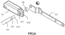
- the adapter device 12 includes an adapter 121 securely attached to the distal free end of each of the sliders 122 for connection to the vehicle's original seat and a second connection rod 123 sandwiched between the two adapters 121.
- Each of the adapter 121 has a connection plate 1210 formed on a distal end of the adapter 121 and having a through hole 1211 defined through the connection plate 1210.
- a respective distal end, e.g., two distal ends, of the second connection rod 123 has a circumferential cutout 1231 and a cylindrical extension 1232, preferably a threaded one, extending out there from.
- a nut (not numbered) is employed to secure engagement of the second connection rod 123 with the adapter 121 as well as the slider 122.
- a cushion 125 made of a soft material, such as rubber, is placed between the connection plate 1210 and the slider 122 to provide a slight lateral shift to the adapter 121 in order to adjust the position of the adapter 121 to mate with the vehicle's seat.
- a first folding device 14 is provided between the base frame 11 and the first support frame 131 to allow the first support frame 131 to fold relative to the base frame 11.
- the first folding device 14 is provided to both sides of the base frame 11 and located between the first side plate 111 and each of the first support frames 1311.
- the first folding device 14 has a first adjusting plate 141 securely attached to a side face of the first side plate 111 and having a first gear set (not numbered) securely attached to a side face of the first adjusting plate 141 a second adjusting plate 142 securely attached to a side face of the first support frame 1311 and having a second gear set securely yet rotatably attached to a side face of the second adjusting plate 142 and mated with the first gear set of the first adjusting plate 141.
- the second adjusting plate 142 further has a sun gear 1431 rotatably mounted on a side face of the first support frame 1311 and a planetary gear 1432 mated with the sun gear 1431 and firmly connected to the second gear set, which allows the planetary gear 1432 to rotate and thus drives the sun gear 1431 to rotate.
- a handle 145 is provided on a side face of the sun gear 1431 so that the operator is able to hold the handle 145 and rotates the sun gear 1431. While the sun gear 1431 is rotated, the first support frame 1311 is able to fold relative to the base frame 111.
- a driving rod 144 may be provided to extend through the planetary gear 1432. Thereafter, the rotation of the sun gear 1431 due to a force exerted thereon is able to drive the first support frame 1311 to fold.
- the first folding device 14' constructed in accordance with the preferred embodiment of the present invention includes a first adjusting plate 141' securely attached to a side face of the first side plate 111'of the base plate, a second adjusting plate 142' securely mounted at a free end of the first support frame 1311' yet rotatably mounted on a side face of the first adjusting plate 141'through a first pivot axis 1431' and having ratchet 145'formed on a distal free end of the second adjusting plate 142', a first spring 146 whose first end is securely connected to the first pivot axis 1431' and second end is securely connected to a side face of the second adjusting plate 142' to allow the first spring 146 to provide a recovery force to the first support frame 1311'when the first support frame 1311'is moved, i.e., pivoted or rotated, relative to the first side plate
- the second spring 148 provides a force to maintain one end of the limiting lever 144' in a low position and the other end of the limiting lever 144'in a high position.
- the free end face with the limiting teeth 1441' is in constant contact with the ratchet 145', which stops the first support frame 1311'from movement relative to the first side plate 111'.
- the first support frame 1311' is able to move freely relative to the first side plate 111', which achieves the goal of adjusting the angle of the back frame relative to the base frame.
- a second folding device 18 between the first support 131 and the second support 132, which allows the second support frame 132 to fold relative to the first support frame 131.
- the second folding device 18 is sandwiched between a pair of horizontally situated first support frames 1311 and a pair of horizontally situated second support frames 1321.
- the second folding device 18 attached between one side of the first support frame 1311 and the second support frame 1321 is described.
- the second folding device 18 includes a first cutout 401 defined in a top periphery of the first support frame 1311, a second cutout 402 defined in a side periphery of the first support frame 1311 and a positioning stop 16 formed on a side face of the first support frame 1311. Furthermore, it is to be noted that the second folding device 18 also has a first joint 17 extending through the first support frame 1311 and into the second support frame 1321 to allow the second support frame 1321 to pivot relative to the first support frame 1311 and having a slit 171 defined in a distal end thereof and a second spring 181, preferably a coil spring, having a first end 1811 securely rested in the slit 171 and a second end 1812 securely rested on the positioning stop 16.
- a cap 180 is provided to cover or enclose the entire first spring 181.
- the second spring 181 of the second folding device 18 is provided on the outside of the first support frame 1311.
- a third spring 182, preferably a leaf spring is provided on the inside of the first support frame 1311 and has a first end securely attached to an inner side face of the first support frame 1311 and a second end provided with a limit 201 formed thereon.
- a limit hole 301 is defined through a side face of the second support frame 1321 so that the limit 201 is able to slide within the limit hole 301.
- the second spring 181 is tension free with the second end securely rested on the positioning stop 16 and the limit 201 inside the limit hole 301 rested inside the first cutout 401, a first position.
- the limit 201 is lifted away from the first cutout 401 to allow the second support frame 1321 to pivot relative to the first support frame 1311.
- a lifter 2011 may be provided to the limit 201.
- the lifter 2011 may be integrally formed on the limit 201 or may be detachably yet firmly connected to the limit 201.
- the technique involved to form the lifter 2011 on the limit 201 or to detachably yet firmly connect the lifter 2011 to the limit 201 is well known in the art and no detailed description thereof is provided for clarity and concise.
- a pillow mount 50 is provided on top of the foldable car seat and has a top beam 133 mounted on free ends of both the third support frame 1321 and the fourth support frame 1322 and a lower beam 134 mounted at a middle portion of both the third support frame 1321 and the fourth support frame 1322.
Landscapes
- Engineering & Computer Science (AREA)
- Aviation & Aerospace Engineering (AREA)
- Transportation (AREA)
- Mechanical Engineering (AREA)
- Health & Medical Sciences (AREA)
- Child & Adolescent Psychology (AREA)
- General Health & Medical Sciences (AREA)
- Seats For Vehicles (AREA)
Description
- The present invention relates to a foldable car seat and, more particularly, to a foldable car seat which is able to be completely folded for storage when not in use.
- Current commercially available child safety seat is targeted to infant or children under age who are legally regulated to put on a safety seat when boarding a vehicle. Normally, the safety seat is positioned at the backseat with the safety belt so that the user (children under age) is able to use it readily. However, due to the bulky design and massive volume the safety seat takes, there is not much room left for other use. Often in time, the driver needs to take it out of the vehicle to clear the backseat so that the driver is able to have room in the back to have extra load such as grocery and/or passengers and when the baby it about to be boarded on the vehicle, the driver will have to strap the safety seat back on again. The on-and-off of the safety seat is quite troublesome and tiresome even though there are all kinds of handy designs on the safety seat to facilitate the driver to carry it around. None of the existing designs enable the driver to fold the car seat completely for storage or to clear the room for extra load.
-
US 2011/0233374 A1 discloses a car seat adapted to connect to a vehicle seat, the car seat comprising a base frame and a sliding frame, slidably attached to an inside of the base frame and having an adapter securely attached to a free end of the sliding frame to adapt to the vehicle seat so that the base frame is able to move relative to the sliding frame, a back frame foldably connected to the base frame, and a locking mechanism provided to the sliding frame to limit extend of the sliding frame. -
US 2008/0258525 A1 discloses a car seat comprising a base, a backrest and a headrest, wherein the base and the headrest are rotatably foldable relative to the backrest. - In order to mitigate the shortcomings from the currently existing safety seat, it is an objective of the preferred embodiment of the present invention to provide a foldable and thus compact car seat so that there is no need to remove the car seat out of the vehicle when the presence of the car seat function inside the vehicle matters none.
- An objective of the present invention is to provide a foldable car seat which is compact when folded.
- In order to accomplish the objective of being compact, there is provided with a base frame, a back frame, a first folding device sandwiched between the base frame and the back frame to allow the back frame to fold relative to the base frame and a second folding device sandwiched in between elements of the back frame so that when the back frame is not in use, the back frame is able to be further folded so that the overall volume is even more compact.
- A further objective of the present invention is that a driving device is provided to the base frame and a sliding frame is slidably connected to the base frame and operably connected to the driving device to allow the sliding frame to move relative to the base frame to accomplish the purpose of adjusting length of the base frame and providing a comfortable seating for the user.
- It is an objective of the present invention to provide a foldable car seat adapted to connect to vehicle seat. The foldable car seat includes a base frame having thereon a driver securely mounted thereon; a sliding frame operably connected to the driver and slidably attached to an inside of the base frame and having an adapter securely attached to a free end of the sliding frame to adapt to the vehicle seat so that the base frame is able to move relative to the sliding frame due to power from the driver; and a back frame foldably connected to the base frame and consisting of a pair of first support frames foldably connected to free ends of the base frame through a first folding device and a pair of second support frames foldably connected to free ends of the pair of first support frames through a second folding device to allow the pair of first support frames to fold relative to the base frame and the pair of second support frames to fold relative to the pair of first support frames.
- The present invention will be further described in connection with the accompanying drawings and specific embodiments.
-
-
Fig. 1 is a perspective view showing a preferred embodiment of the present invention; -
Fig. 2 is still a perspective view of the preferred embodiment of the present invention where the second support frame is folded relative to the first support frame of the back frame; -
Fig. 3 shows a perspective view of the base frame of the preferred embodiment of the present invention; -
Fig. 4 is a perspective view of the base frame together with a sliding frame movably attached to an inside of the base frame; -
Fig. 5 is an exploded perspective view structural relationship between the base frame and the sliding frame; -
Fig. 6 is still an exploded perspective view showing how the sliding frame is connected to an adapter; -
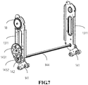
Fig. 7 is a schematic view showing the relationship between the first folding device and the first support frame of the back frame of the preferred embodiment of the present invention; -
Fig. 8 is a schematic side plan view showing how the first folding device is sandwiched between the base frame and the first support frame of the preferred embodiment of the present invention; -
Fig. 9 is still a schematic side plan view of what is shown inFig. 8 ; -
Fig. 10 is a schematic side plan view showing the first support frame is in parallel relative to the base frame due to the operation of the first folding device; -
Fig. 11 is a schematic side plan view showing another embodiment of the first folding device between the first support frame and the base frame; -
Fig. 12 is a schematic side plan view showing the movement of the first support frame relative to the base due to the first folding device; -
Fig. 13 is a schematic side plan view showing that the first support frame is locked by the first folding device; -
Fig. 14 is an exploded perspective view showing elements of the second folding device and relationship with the back frame; -
Fig. 15 is a schematic side plan view indicating how the second folding device is mounted onto the back frame; -
Fig. 16 is a schematic side plan view showing a leaf spring is provided to an inner side of the back frame; -
Fig. 17 is a schematic side plan view showing how the second folding device operates when the second support frame is folded relative to the first support frame; and -
Fig. 18 is a schematic side plan view showing how the leaf spring operates when the second support frame is folded relative to the first support frame. - The present invention will be described further in connection with the accompanying drawings and specific embodiment(s).
- With reference to
Figs. 1 ,2 and3 , it is to be noted that the foldable car seat constructed in accordance with the present invention includes abase frame 11 and aback frame 13 foldable relative to thebase frame 11 with the assistance of afirst folding device 14 which is sandwiched between thebase frame 11 and bottom of theback frame 13. Thebase frame 11 has a pair ofside plates 111 horizontally located relative to one another and afirst connection rod 112 securely connected to a distal end of both theside plates 111 to respectively secure relative locations of the twoside plates 111. Still, asupport frame 113 is securely provided between the twoside plates 111. Theback frame 13 is composed of afirst support 131 foldably connected to a distal end of thebase frame 11 and asecond support 132 foldably connected to a distal end of thefirst support 131. Thefirst support 131 consists of a pair of oppositely locatedfirst support frames 1311 and thesecond support 132 consists of a pair of oppositely located second support frames 1312. Preferably, theside plate 111 is made of a steel or iron having a bending stress larger than 200 Mpa, or a nylon material with or larger than 25% fiber glass, or Polyamide (PA)+Acrylonitrile Butadiene Styrene (ABS) compound material, or a carbonated fiber material or an alloy of aluminum and magnesium, or a titanium alloy or a magnesium alloy. - With reference to
Figs. 3, 4 and5 , a sliding frame is provided inside the pair offirst side plates 111 of thebase frame 11 and has a pair ofsliders 122 slidably connected to an inside of each of the pair offirst side plates 111. Both thesliders 122 are, preferably, elongate in shape and have substantially the same structure. Thus, for brevity, the following description will focus on the detailed structure of the oneslider 122 as well as the relationship between the oneslider 122 and theside plate 111 of thebase frame 11. It is appreciated that thefirst side plate 111 defines there throughfirst bores 1111, preferably elongated in shape. Theslider 122 includes a body, a pair offirst stops 1221 securely mounted on or attached to a side face of the body and respectively having a centrally defined through hole (not numbered), a pair ofbolts 1222 extendable through thefirst bores 1111 of theside plate 111 of thebase frame 11 and a pair ofnuts 1223 securely and threadingly attached to the bolts 1512 after the pair ofbolts 1222 are extended through thefirst bores 1111, the centrally defined through hole of thefirst stops 1221 and theslider 122. It is understandable that even thebolts 1222 are securely and threadingly attached to thenuts 1223, thesliders 122 are still able to slide relative to both of theside plates 111 with the assistance of the pair offirst stops 1221 partially received within thefirst bores 1111 to limit extent of movement of theslider 122 relative to theside plate 111. Furthermore, to synchronize the movement of both of thesliders 122, anauxiliary rod 153 may be employed to have secure engagement with each of thesliders 122 respectively. With such an arrangement and the help from theauxiliary rod 153, the movement of both of thesliders 122 is thus synchronized. Furthermore, in order to selectively secure the location of thesliders 122, a locking mechanism is provided to thesliders 122 so that whenever thesliders 122 are moved manually or with the help of electricity to an angle where the passenger feels comfortable, the locations of both of thesliders 122 may be locked to provide a pleasant seating comfort to the passenger. The locking mechanism includes alever 151 whose first distal free end is pivotally connected or attached to a side face of each of thesliders 122 and whose second distal free end extends out of the side face of each of thesliders 122 and is provided with aknob 1511 for facilitating maneuvering movement of thelever 151 by an operator. The locking mechanism also has aspring 152 whose first distal end is securely attached to a side face of each of thesliders 122 and whose second distal end is securely connected to a rear side face of thelever 151 to provide theknob 1511 an upward push to constantly maintain theknob 1511 in a high up position. Alimiting track 114 defined through the side face of each of theside plates 111 is also included in the locking mechanism and hasmultiple position cutouts 1141 defined in a periphery defining thelimiting track 114 to correspond to theknob 1511 of thelever 151. Thus, when theknob 1511 is received in one of theposition cutouts 1141, thespring 152 provides a push to thelever 151 to maintain theknob 1511 within theposition cutout 1141 and, therefore, position of both of thesliders 122 is secured. When adjustment of thesliders 122 is required, the operator may depress thelever 1511 to lower thelever 151, theknob 1511 then escapes from the one of theposition cutout 1141 and thesliders 122 are able to move freely along thefirst bores 1111 until theknob 1511 is received in adifferent position cutout 1141 after the operator releases thelever 151. - It is noted from the common knowledge that both the
sliders 122 and thefirst side plate 111 are made of metal and friction therebetween will gradually damage side faces of each of thesliders 122 and theside plates 111. In order to decrease the friction therebetween, apad frame 124, preferably made of rubber, is provided between theslider 122 and thecorresponding side plate 111 and hassecond bores 1241 defined there through to correspond to thefirst bores 1111 of theside plate 111 and aflange 12411 formed on a periphery defining each of thesecond bores 1241 and extending into a corresponding one of thefirst bores 1111 of theside plate 111. As the shape and location of each of thesecond bores 1241 correspond to those of thefirst bores 1111 of theside plate 111, thefirst stops 1221 easily extend through thesecond bores 1241 as well as thefirst bores 1111 to mate with thebolts 1222. - With reference to
Fig. 6 , to increase the adaptability of the car seat of the preferred embodiment of the present invention with the vehicle's original seat, an adapter device 12 is provided to a distal free end of each of thesliders 122. With reference toFig. 6 and still takingFig. 1 for reference, the adapter device 12 includes anadapter 121 securely attached to the distal free end of each of thesliders 122 for connection to the vehicle's original seat and asecond connection rod 123 sandwiched between the twoadapters 121. Each of theadapter 121 has aconnection plate 1210 formed on a distal end of theadapter 121 and having a throughhole 1211 defined through theconnection plate 1210. A respective distal end, e.g., two distal ends, of thesecond connection rod 123 has acircumferential cutout 1231 and acylindrical extension 1232, preferably a threaded one, extending out there from. After thecylindrical extension 1232 extends through the throughhole 1211 as well as a hole (not numbered) in each of thesliders 122, a nut (not numbered) is employed to secure engagement of thesecond connection rod 123 with theadapter 121 as well as theslider 122. Acushion 125 made of a soft material, such as rubber, is placed between theconnection plate 1210 and theslider 122 to provide a slight lateral shift to theadapter 121 in order to adjust the position of theadapter 121 to mate with the vehicle's seat. - With reference to
Figs. 7 ,8 ,9 and10 , afirst folding device 14 is provided between thebase frame 11 and thefirst support frame 131 to allow thefirst support frame 131 to fold relative to thebase frame 11. Thefirst folding device 14 is provided to both sides of thebase frame 11 and located between thefirst side plate 111 and each of the first support frames 1311. Thefirst folding device 14 has afirst adjusting plate 141 securely attached to a side face of thefirst side plate 111 and having a first gear set (not numbered) securely attached to a side face of the first adjusting plate 141 asecond adjusting plate 142 securely attached to a side face of thefirst support frame 1311 and having a second gear set securely yet rotatably attached to a side face of thesecond adjusting plate 142 and mated with the first gear set of thefirst adjusting plate 141. Thesecond adjusting plate 142 further has asun gear 1431 rotatably mounted on a side face of thefirst support frame 1311 and aplanetary gear 1432 mated with thesun gear 1431 and firmly connected to the second gear set, which allows theplanetary gear 1432 to rotate and thus drives thesun gear 1431 to rotate. To facilitate the rotation of thesun gear 1431, ahandle 145 is provided on a side face of thesun gear 1431 so that the operator is able to hold thehandle 145 and rotates thesun gear 1431. While thesun gear 1431 is rotated, thefirst support frame 1311 is able to fold relative to thebase frame 111. Still, in order to synchronize the movement of the two sets of sun gear-planetary gear, a drivingrod 144 may be provided to extend through theplanetary gear 1432. Thereafter, the rotation of thesun gear 1431 due to a force exerted thereon is able to drive thefirst support frame 1311 to fold. - With reference to
Figs. 11 ,12 and 13 , a different embodiment of the first folding device 14' is shown, wherein the first folding device 14' constructed in accordance with the preferred embodiment of the present invention includes a first adjusting plate 141' securely attached to a side face of the first side plate 111'of the base plate, a second adjusting plate 142' securely mounted at a free end of the first support frame 1311' yet rotatably mounted on a side face of the first adjusting plate 141'through a first pivot axis 1431' and having ratchet 145'formed on a distal free end of the second adjusting plate 142', a first spring 146 whose first end is securely connected to the first pivot axis 1431' and second end is securely connected to a side face of the second adjusting plate 142' to allow the first spring 146 to provide a recovery force to the first support frame 1311'when the first support frame 1311'is moved, i.e., pivoted or rotated, relative to the first side plate 111'of the base frame, a limiting lever 144'pivotally mounted on the first adjusting plate 141'via a second pivot axis 1432' which is securely provided on a side face of the first adjusting plate 141'and a second spring 148 whose first end is securely connected to a side face of the limiting lever 144'and second end is securely attached to a side face of the first adjusting plate 141'. The limiting lever 144' is provided with a series of limiting teeth 1441' formed on a free end face of the limiting lever 144' and corresponding to the ratchet 145'of the second adjusting plate 142'. - It is appreciated that the
second spring 148 provides a force to maintain one end of the limiting lever 144' in a low position and the other end of the limiting lever 144'in a high position. With this arrangement, the free end face with the limiting teeth 1441' is in constant contact with the ratchet 145', which stops the first support frame 1311'from movement relative to the first side plate 111'. However, when the free end of the limiting lever 144'is lifted to free the engagement between the limiting teeth 1441' and the ratchet 145', the first support frame 1311' is able to move freely relative to the first side plate 111', which achieves the goal of adjusting the angle of the back frame relative to the base frame. - With reference to
Figs. 14 to 18 and still takingFig. 1 as reference, as described earlier, there is provided with asecond folding device 18 between thefirst support 131 and thesecond support 132, which allows thesecond support frame 132 to fold relative to thefirst support frame 131. To be more precise, thesecond folding device 18 is sandwiched between a pair of horizontally situated first support frames 1311 and a pair of horizontally situated second support frames 1321. Here, to avoid any possible confusing and misunderstanding resulted from overly describing repeated elements, only thesecond folding device 18 attached between one side of thefirst support frame 1311 and thesecond support frame 1321 is described. - The
second folding device 18 includes afirst cutout 401 defined in a top periphery of thefirst support frame 1311, asecond cutout 402 defined in a side periphery of thefirst support frame 1311 and apositioning stop 16 formed on a side face of thefirst support frame 1311. Furthermore, it is to be noted that thesecond folding device 18 also has a first joint 17 extending through thefirst support frame 1311 and into thesecond support frame 1321 to allow thesecond support frame 1321 to pivot relative to thefirst support frame 1311 and having aslit 171 defined in a distal end thereof and asecond spring 181, preferably a coil spring, having afirst end 1811 securely rested in theslit 171 and asecond end 1812 securely rested on thepositioning stop 16. In order to protect the user from being hurt by thesecond spring 181, acap 180 is provided to cover or enclose the entirefirst spring 181. From the accompanying drawings, it is appreciated that thesecond spring 181 of thesecond folding device 18 is provided on the outside of thefirst support frame 1311. Opposite to the location of thesecond spring 181, athird spring 182, preferably a leaf spring, is provided on the inside of thefirst support frame 1311 and has a first end securely attached to an inner side face of thefirst support frame 1311 and a second end provided with alimit 201 formed thereon. To accommodate thelimit 201, alimit hole 301 is defined through a side face of thesecond support frame 1321 so that thelimit 201 is able to slide within thelimit hole 301. - It is noted that when the
first support frame 1311 and thesecond support frame 1321 is in parallel relative to each other, thesecond spring 181 is tension free with the second end securely rested on thepositioning stop 16 and thelimit 201 inside thelimit hole 301 rested inside thefirst cutout 401, a first position. However, before thesecond support frame 1321 is folded relative to thefirst support frame 1311 and an angle of 90 degree(s) between thesecond support frame 1321 and thefirst support frame 1311 is expected, thelimit 201 is lifted away from thefirst cutout 401 to allow thesecond support frame 1321 to pivot relative to thefirst support frame 1311. When the angle of 90 degree(s) between thefirst support frame 1311 and thesecond support frame 1321 is reached, it is observed that thelimit 201 is now shifted to thesecond cutout 402. After thelimit 201 is securely rested inside thesecond cutout 402 due to the tension from thesecond spring 182, relative position of thesecond support frame 1321 to thefirst support frame 1311 is fixed and the folded car seat is shown inFig. 2 . In order to readily facilitate movement of thelimit 201, alifter 2011 may be provided to thelimit 201. Thelifter 2011 may be integrally formed on thelimit 201 or may be detachably yet firmly connected to thelimit 201. The technique involved to form thelifter 2011 on thelimit 201 or to detachably yet firmly connect thelifter 2011 to thelimit 201 is well known in the art and no detailed description thereof is provided for clarity and concise. - To increase comfort, a
pillow mount 50 is provided on top of the foldable car seat and has atop beam 133 mounted on free ends of both thethird support frame 1321 and the fourth support frame 1322 and a lower beam 134 mounted at a middle portion of both thethird support frame 1321 and the fourth support frame 1322. - Although the invention has been described in connection with the embodiments shown in the accompanying drawings, a person having ordinary skill in the art can make various modifications to the invention based on the above descriptions. Therefore, some details of the embodiment should not be construed to restrict the invention. The scope of the invention is limited by the accompanying claims.
Claims (9)
- A foldable car seat adapted to connect to a vehicle seat, the foldable car seat comprising a base frame (11), a sliding frame slidably attached to an inside of the base frame (11) and having an adapter securely attached to a free end of the sliding frame to adapt to the vehicle seat so that the base frame (11) is able to move relative to the sliding frame, wherein a locking mechanism is provided to the sliding frame to limit extent of the sliding frame movement as well as to position location of the sliding frame relative to the base frame , characterized by
a back frame (13) which is foldably connected to the base frame (11);
the back frame (13) consists of
a lower support frame (131) foldably connected to free ends of the base frame (11) through a first folding device (14) to allow the lower support frame (131) to fold relative to the base frame (11) and an upper support frame (132) foldably connected to free ends of the lower support frame (131) through a second folding device (18) to allow the upper support frame (132) to fold relative to the lower support frame (131);
wherein the base frame (11) further comprises a pair of horizontally located first side plates (111) each having at least one bore (1111) defined through a side face thereof, and
the sliding frame has a pair of sliders (122) respectively and slidably attached to a side face of each of the horizontally located first side plates (111) and having at least one stop (1221) formed on a side face thereof and movably received in the at least one bore (1111) of the first side plates (111) to limit movement extent of the sliders (122). - The foldable car seat as claimed in claim 1, wherein locking mechanism has a lever (151) whose first end is pivotally connected to a side face of a respective one of the pair of sliders (122) and second end is provided with a knob (1511), a limiting track (114) adapted to be defined in the side face of each one of the pair of the first side plates (111) to receive therein the knob (1511) and position cutouts (1141) defined in a periphery defining the limiting track (114) to selectively receive therein the knob (1511) of the lever (151) so as to position location of the pair of sliders (122) relative to the pair of first side plates (111) of the base frame (11).
- The foldable car seat as claimed in claim 1, wherein the lower support frame (131) includes a pair of first support frames (1311) foldably connected to distal ends of the first side plates (111), the first folding device (14) is located at a joint between each of the first support frames (1311) and each of the first side plates (111) so that both of the first support frames (1311) are able to fold simultaneously relative to the base frame (11) due to a driving rod (144) sandwiched between the pair of first support frames (1311) and extending into the first folding device (14) to synchronize movement of the first folding device (14) on both sides of the pair of the back frame (13).
- The foldable car seat as claimed in claim 3, wherein the first folding device (14) includes a first adjusting plate (141) securely attached to the first side plate (111), a second adjusting plate (142) securely attached to the first support frame (1311) yet rotatably connected to the first adjusting plate (141), a sun gear (1431) rotatably mounted on a side face of the first support frame (1311) and a planetary gear (1432) mated with the sun gear (1431) and firmly connected to the driving rod (144), and a handle (145) provided on a side face of the sun gear (1431) to facilitate rotation of the first support frame (1311) so that the first support frame (1311) is foldable relative to the first side plate (111).
- The foldable car seat as claimed in claim 2, wherein the first folding device (14) includes a first adjusting plate (141) securely attached to the first side plate (111), a second adjusting plate (142) securely attached to the first support frame (1311) yet rotatably connected to the first adjusting plate (141) via a first pivot axis (1431') and having a ratchet (145) formed on a free end of the second adjusting plate (142'), a first spring (146) whose first end is securely connected to a side face of the first support frame (1311) and second end is securely connected to a side face of the second adjusting plate (142') to provide a recoil force to the first support frame (1311) after the first support frame (1311) is moved relative to the first side plate (111'), and a limiting lever (144') pivotally connected to the first adjusting plate (141') and having a limiting teeth (1441') formed to selectively mate with the ratchet (145) of the second adjusting plate (142') so that when the ratchet (145) is mated with the limiting teeth (1441'), the first support frame (1311) is stopped from movement and when the limiting teeth (1441') is disconnected to the ratchet (145), the first support frame (1311) is free to move relative to the first adjusting plate (141').
- The foldable car seat as claimed in claim 5, wherein a second spring (148) is provided to provide to a side face of the limiting lever (144') and a side face of the first adjusting plate (141') such that a recovery force is provided to the limiting lever (144') after the limiting lever (144') is moved.
- The foldable car seat as claimed in claim 6, wherein the second folding device (18) includes a joint respectively inserted between each of the first support frames (1311) and each of the second support frame (1321) to allow the second support frame (1321) to pivot relative to the first support frame (1311),
a spring (181) having a first end securely rested in a free end of the joint and a second end securely attached to a side face of the first support frame (1311) so that when the second support frame (1321) is parallel relative to the first support frame (1311), the spring (181) is tension free and when the second support frame (1321) is vertical relative to the first support frame (1311), the first spring (181) is tensioned,
a first cutout (401) defined in a top periphery of the first support frame (1311) and a second cutout (402) defined in a side periphery of the first support frame (1311) and a limit (201) selectively located in the first cutout (401) and the second cutout (402) to respectively position the second support frame (1321) to be parallel or vertical relative to the first support frame (1311),
a second spring (182) having a first end securely respectively attached to an inner side face of the second support frame (1321) and a second end securely attached to the limit (201) to allow the limit (201) to be retracted after the limit (201) is moved. - The foldable car seat as claimed in claim 7 further comprising a pillow mount (50) having a top beam (133) mounted on free ends of both the second support frame (1321) and a lower beam (134) mounted at a middle portion of both the second support frames (1321).
- The foldable car seat as claimed in claim 1, wherein the first side plate (111) is made of a material selected from the group consisting of steel or iron having a bending stress larger than 200 Mpa, a nylon material with or larger than 25% fiber glass, Polyamide (PA)+Acrylonitrile Butadiene Styrene (ABS) compound material, a carbonated fiber material, an alloy of aluminum and magnesium, a titanium alloy and a magnesium alloy.
Applications Claiming Priority (2)
| Application Number | Priority Date | Filing Date | Title |
|---|---|---|---|
| CN201610214003.4A CN107264348B (en) | 2016-04-07 | 2016-04-07 | Folding manual child safety seat |
| PCT/CN2016/082593 WO2017173711A1 (en) | 2016-04-07 | 2016-05-19 | Foldable manual child safety seat |
Publications (3)
| Publication Number | Publication Date |
|---|---|
| EP3446919A1 EP3446919A1 (en) | 2019-02-27 |
| EP3446919A4 EP3446919A4 (en) | 2019-06-05 |
| EP3446919B1 true EP3446919B1 (en) | 2020-08-19 |
Family
ID=60000208
Family Applications (1)
| Application Number | Title | Priority Date | Filing Date |
|---|---|---|---|
| EP16754162.2A Active EP3446919B1 (en) | 2016-04-07 | 2016-05-19 | Foldable manual child safety seat |
Country Status (7)
| Country | Link |
|---|---|
| US (1) | US9969306B1 (en) |
| EP (1) | EP3446919B1 (en) |
| JP (1) | JP6449899B2 (en) |
| KR (1) | KR101966677B1 (en) |
| CN (1) | CN107264348B (en) |
| ES (1) | ES2829255T3 (en) |
| WO (1) | WO2017173711A1 (en) |
Families Citing this family (11)
| Publication number | Priority date | Publication date | Assignee | Title |
|---|---|---|---|---|
| CN106740310B (en) * | 2017-01-06 | 2019-06-28 | 上海沃雨电子科技有限公司 | System and method for interlocking adjustment of isofix and backrest of child safety seat |
| WO2020017833A1 (en) | 2018-07-16 | 2020-01-23 | Dong-In Entech Co., Ltd. | Portable car seat |
| US11046213B2 (en) * | 2019-01-08 | 2021-06-29 | Ford Global Technologies, Llc | Seating assembly bracket |
| US11219338B2 (en) | 2019-03-11 | 2022-01-11 | Storyteller Overland, LLC. | RV retrofit system |
| KR102348183B1 (en) * | 2020-04-09 | 2022-01-06 | 황종성 | A chair |
| KR102923449B1 (en) * | 2020-10-12 | 2026-02-06 | 현대자동차주식회사 | Seat Having Dual Gear Type Recliner Device for Vehicle |
| CN114246434B (en) * | 2021-11-19 | 2024-06-04 | 好孩子儿童用品有限公司 | A children's bed |
| DE102022107289B4 (en) * | 2022-03-28 | 2024-12-19 | Dr. Ing. H.C. F. Porsche Aktiengesellschaft | vehicle seat |
| CN115352337B (en) * | 2022-07-22 | 2024-10-01 | 安徽艾文德汽车内饰有限公司 | Multifunctional automobile seat for new energy automobile |
| CN219270552U (en) * | 2023-02-18 | 2023-06-30 | 顾家家居股份有限公司 | Sofa with backrest folding function |
| DE102023104194B3 (en) | 2023-02-21 | 2024-06-06 | Lisa Dräxlmaier GmbH | SWIVEL DEVICE FOR A VEHICLE |
Family Cites Families (72)
| Publication number | Priority date | Publication date | Assignee | Title |
|---|---|---|---|---|
| JPS5818830U (en) * | 1981-07-30 | 1983-02-05 | 株式会社 タチエス | vehicle seat |
| US4902070A (en) * | 1988-09-16 | 1990-02-20 | Child Riding Incorporated | Foldable automobile convertible seat |
| FR2642377B1 (en) * | 1989-01-31 | 1991-05-17 | Equip Composants Ind Auto | RECLINING AND FOLDING-BACK SEAT |
| GB2247165B (en) * | 1990-08-21 | 1993-03-24 | Aviat Furnishings Internationa | Seats for children |
| US5123377A (en) * | 1991-09-23 | 1992-06-23 | Edwards Myrtis C | Collapsible vehicle safety restraint and seat for pets |
| US5435624A (en) * | 1993-10-12 | 1995-07-25 | Ford Motor Company | Powered vehicle seat |
| AT1134U1 (en) * | 1995-12-19 | 1996-11-25 | Hutter Frederik | CHILD SEAT |
| DE19650087C1 (en) * | 1996-12-03 | 1997-12-04 | Faure Bertrand Sitztech Gmbh | Device for releasable fixture of child seat to vehicle seat with foldable back rest |
| FR2766139B1 (en) * | 1997-07-18 | 1999-09-17 | Faure Bertrand Equipements Sa | ARTICULATION DEVICE FOR VEHICLE SEAT, AND VEHICLE SEAT COMPRISING SUCH A DEVICE |
| US6076890A (en) * | 1997-08-08 | 2000-06-20 | Ikeda Bussan Co., Ltd. | Seat for vehicle |
| US6139104A (en) * | 1999-01-29 | 2000-10-31 | Johnson Controls Technology Company | Multiple function seat back adjusting mechanism |
| DE19915780C1 (en) * | 1999-04-08 | 2001-01-25 | Faure Bertrand Sitztech Gmbh | Device for locking a foldable backrest |
| FR2796015B1 (en) * | 1999-07-08 | 2001-10-12 | Antolin Grupo Ing Sa | DEVICE FOR ADJUSTING A DOUBLE ARTICULATED SEAT BACK BY A SINGLE CONTROL |
| FR2799420B1 (en) * | 1999-10-08 | 2002-01-04 | Faure Bertrand Equipements Sa | VEHICLE SEAT |
| NO311553B1 (en) * | 2000-03-07 | 2001-12-10 | Reagan W James | Foldable highchair |
| US6513876B1 (en) * | 2000-11-17 | 2003-02-04 | Gayle D. Agler | Multiple function boat seat |
| JP2002178811A (en) * | 2000-12-14 | 2002-06-26 | Takata Corp | Child seat device |
| FR2825955B1 (en) * | 2001-06-15 | 2005-10-14 | Faurecia Automotive Seating Ca | IMPROVED VEHICLE SEAT JOINT MECHANISM |
| FR2829439B1 (en) * | 2001-09-07 | 2004-01-16 | Faurecia Sieges Automobile | VEHICLE SEAT BASE, SEAT COMPRISING SUCH A BASE AND SEAT ASSEMBLY COMPRISING SUCH A SEAT |
| US6733076B2 (en) * | 2002-09-24 | 2004-05-11 | Bae Industies, Inc. | Seatback recliner mechanism incorporating forward fold flat capability from any forward rearward reclined position |
| US7229132B2 (en) * | 2002-09-27 | 2007-06-12 | Meeker R & D, Inc. | Foldable booster car seat |
| US6908151B2 (en) * | 2003-03-07 | 2005-06-21 | Meeker R&D, Inc. | Adjustable and foldable booster car seat |
| DE10315375A1 (en) * | 2003-04-03 | 2004-11-11 | Keiper Gmbh & Co. Kg | Fitting system for a vehicle seat |
| US6910739B2 (en) * | 2003-08-27 | 2005-06-28 | Bae Industries, Inc. | Seat recliner mechanism incorporating rotatable seatback slaved to a floor latch release |
| CA2556916A1 (en) * | 2004-02-23 | 2005-09-01 | Vadai, Doron | Collapsible portable child safety seat |
| US7097253B2 (en) * | 2004-03-11 | 2006-08-29 | Fisher Dynamics Corporation | Round recliner assembly with rear folding latch |
| US7025422B2 (en) * | 2004-03-11 | 2006-04-11 | Fisher Dynamics Corporation | Round recliner assembly with rear folding latch |
| US7475941B2 (en) * | 2004-05-28 | 2009-01-13 | Skjp Holdings Llc | Compact folding seat with reverse cantilevered pivot |
| US7380878B2 (en) * | 2004-05-28 | 2008-06-03 | Skjp Holdings, Llc | Compact folding seat |
| US20060006712A1 (en) * | 2004-07-12 | 2006-01-12 | David Clement | Folding seat with improved structural linkage |
| US7303230B2 (en) * | 2005-06-10 | 2007-12-04 | Cosco Management, Inc. | Juvenile vehicle seat with quick-connect backrest |
| US7364237B2 (en) * | 2005-07-25 | 2008-04-29 | Bae Industries, Inc. | Seat assembly including a toothed pawl interengageable with a seatback |
| US7419217B2 (en) * | 2006-01-12 | 2008-09-02 | Tachi-S Co. Ltd. | Reclining device of two-point hinged type for seat |
| ES1063434Y (en) * | 2006-07-14 | 2007-01-16 | Jane Sa | BASE FOR THE COUPLING OF CHILD SEATS IN CARS |
| DE102006043205B4 (en) * | 2006-09-11 | 2011-03-10 | Johnson Controls Gmbh | Vehicle seat with rotatable and essentially displaceable backrest |
| US7823974B2 (en) * | 2007-03-13 | 2010-11-02 | Cosco Management, Inc. | Lock for forward-folding backrest |
| US7758120B2 (en) * | 2007-03-13 | 2010-07-20 | Cosco Management, Inc. | Compactible juvenile vehicle seat with forward-folding backrest and u-shaped backrest frame |
| US7837267B2 (en) * | 2007-03-13 | 2010-11-23 | Cosco Management, Inc, | Lock for forward-folding backrest |
| US7857385B2 (en) * | 2007-03-13 | 2010-12-28 | Cosco Management, Inc. | Compactible juvenile vehicle seat with forward-folding backrest and retractable armrests |
| EP1970247A1 (en) * | 2007-03-15 | 2008-09-17 | Team-Tex | Device for mounting a child seat in a car and a child seat |
| JP2008247187A (en) * | 2007-03-30 | 2008-10-16 | Aisin Seiki Co Ltd | Vehicle seat device |
| US7845726B2 (en) * | 2007-04-20 | 2010-12-07 | Cosco Management, Inc. | Compactible juvenile vehicle seat |
| US7547066B2 (en) * | 2007-04-20 | 2009-06-16 | Cosco Management, Inc. | Juvenile vehicle seat with forward-folding headrest and rearward-folding foundation |
| US7740309B2 (en) * | 2007-05-18 | 2010-06-22 | Mayercheck Robert P | Folding chair |
| EP2269864A4 (en) * | 2008-03-26 | 2015-04-22 | Ts Tech Co Ltd | Stowable vehicle seat |
| US8182034B2 (en) * | 2009-01-14 | 2012-05-22 | Glance Patrick M | Foldaway child booster seat |
| CN201538348U (en) * | 2009-03-26 | 2010-08-04 | 宝钜儿童用品香港股份有限公司 | child seat |
| DE102009021211B4 (en) * | 2009-05-13 | 2013-08-08 | Johnson Controls Gmbh | vehicle seat |
| US8240762B2 (en) * | 2009-12-03 | 2012-08-14 | Louis Herzberg | Single, multiple and integrated car seat systems |
| DE102010000780B4 (en) * | 2010-01-11 | 2012-01-12 | Takata-Petri Ag | Fastening device for a child car seat and vehicle child seat |
| US8152236B1 (en) * | 2010-02-18 | 2012-04-10 | Amanda Romero | Adjustable child restraining apparatus |
| CN102985286B (en) * | 2010-03-24 | 2015-12-16 | 谛欧诺有限责任公司 | Tilt to ride obforms child seat |
| US8567866B2 (en) * | 2010-06-18 | 2013-10-29 | Ascanio Carimati Di Carimate | Stroller seat pod |
| KR101430096B1 (en) * | 2010-08-04 | 2014-08-13 | 존슨 컨트롤스 게엠베하 | Fixing device for a vehicle seat and vehicle seat |
| DE202010013486U1 (en) * | 2010-09-20 | 2011-02-10 | Bombardier Transportation Gmbh | Armchair for rail vehicles |
| JP5316557B2 (en) * | 2011-02-02 | 2013-10-16 | アイシン精機株式会社 | Seat adjustment device and vehicle seat device provided with the seat adjustment device |
| CN102275531B (en) * | 2011-05-23 | 2013-06-26 | 湖南大学 | Multifunctional child safety seat |
| JP5814672B2 (en) * | 2011-07-19 | 2015-11-17 | 株式会社カーメイト | child seat |
| WO2013028628A2 (en) * | 2011-08-19 | 2013-02-28 | Baby Trend, Inc. | Child car seat and base |
| CN105365616B (en) * | 2011-11-17 | 2018-11-06 | 明门香港股份有限公司 | Child safety seat assembly |
| CN103241148B (en) * | 2012-02-06 | 2015-10-07 | 宝钜儿童用品香港股份有限公司 | Child Safety Seat Fixing Mechanism |
| CN202686016U (en) * | 2012-04-01 | 2013-01-23 | 麦克英孚(宁波)婴童用品有限公司 | Child safety seat for car |
| CN103419687B (en) * | 2012-05-15 | 2016-01-27 | 明门香港股份有限公司 | Fixtures for child safety seats |
| CN203713613U (en) * | 2013-08-15 | 2014-07-16 | 中山市隆成日用制品有限公司 | Safety display equipment capable of locking infant automobile safety chair |
| CN203472593U (en) * | 2013-08-15 | 2014-03-12 | 中山市隆成日用制品有限公司 | Base locking device combined with child car safety seat |
| CN203995784U (en) * | 2014-03-12 | 2014-12-10 | 好孩子儿童用品有限公司 | Foldable child automotive safety seat |
| CN203805742U (en) * | 2014-03-18 | 2014-09-03 | 好孩子儿童用品有限公司 | Foldable child safety seat of car |
| JP6328228B2 (en) * | 2014-03-31 | 2018-05-23 | コンビ株式会社 | child seat |
| CN104590063B (en) * | 2014-12-24 | 2017-08-25 | 厦门金龙汽车座椅有限公司 | Seat connects switching mechanism |
| JP3199855U (en) * | 2015-03-13 | 2015-09-10 | グッドベイビー チャイルド プロダクツ カンパニー リミテッド | Folding child seat |
| CN204978314U (en) * | 2015-08-12 | 2016-01-20 | 上海初德电气有限公司 | Car seat's ISOFIX electric telescopic device |
| CN205059325U (en) * | 2015-08-26 | 2016-03-02 | 常州安宝宝儿童座椅有限公司 | Child safety seat ISOFIX connecting device |
-
2016
- 2016-04-07 CN CN201610214003.4A patent/CN107264348B/en active Active
- 2016-05-19 EP EP16754162.2A patent/EP3446919B1/en active Active
- 2016-05-19 KR KR1020177026741A patent/KR101966677B1/en not_active Expired - Fee Related
- 2016-05-19 JP JP2016554727A patent/JP6449899B2/en not_active Expired - Fee Related
- 2016-05-19 WO PCT/CN2016/082593 patent/WO2017173711A1/en not_active Ceased
- 2016-05-19 ES ES16754162T patent/ES2829255T3/en active Active
- 2016-05-19 US US15/117,636 patent/US9969306B1/en active Active
Non-Patent Citations (1)
| Title |
|---|
| None * |
Also Published As
| Publication number | Publication date |
|---|---|
| JP6449899B2 (en) | 2019-01-09 |
| CN107264348B (en) | 2020-03-31 |
| EP3446919A1 (en) | 2019-02-27 |
| US20180111516A1 (en) | 2018-04-26 |
| KR101966677B1 (en) | 2019-04-09 |
| EP3446919A4 (en) | 2019-06-05 |
| WO2017173711A1 (en) | 2017-10-12 |
| ES2829255T3 (en) | 2021-05-31 |
| JP2018514428A (en) | 2018-06-07 |
| CN107264348A (en) | 2017-10-20 |
| KR20170130426A (en) | 2017-11-28 |
| US9969306B1 (en) | 2018-05-15 |
Similar Documents
| Publication | Publication Date | Title |
|---|---|---|
| US9969306B1 (en) | Foldable car seat | |
| EP3248835B1 (en) | Folding electric child safety seat | |
| CN201254113Y (en) | Spring loaded backrest cushion component | |
| US8585075B2 (en) | Stroller and support-frame adjusting device | |
| US20150258914A1 (en) | Seat cushion extension apparatus | |
| US9445961B2 (en) | Table for wheelchair and wheelchair comprising same | |
| US20220395411A1 (en) | Mobility device seat | |
| JP5164242B2 (en) | Children's seat and telescopic adjustable foot support | |
| KR101619239B1 (en) | A folding wheelchair | |
| EP1736356B1 (en) | A vehicle fitting | |
| CN104105529B (en) | Rest for supporting head or neck | |
| CN208962939U (en) | Headrest may be reversed in one kind | |
| CN201264546Y (en) | Seat headrest regulating mechanism with four-direction regulation function and rotation function | |
| US12201566B2 (en) | Head support assembly and head support unit | |
| CN119348517A (en) | A comfortable and protective military vehicle seat design method and seat | |
| US10946916B1 (en) | Assisted spring seat height optimization lift | |
| JP5964154B2 (en) | wheelchair | |
| JP2004223169A (en) | Wheelchair | |
| JP5650555B2 (en) | Narrow wheelchair | |
| JPH0420670Y2 (en) | ||
| CN106132771B (en) | Portable headrest | |
| EP3831353B1 (en) | Backrest assembly and wheelchair therewith | |
| CN206938515U (en) | For vehicle chair framework and there is its seat | |
| JP2023138887A (en) | Wheelchair for getting over level difference | |
| JP2023101426A (en) | Wheelchair for step climbing |
Legal Events
| Date | Code | Title | Description |
|---|---|---|---|
| STAA | Information on the status of an ep patent application or granted ep patent |
Free format text: STATUS: UNKNOWN |
|
| STAA | Information on the status of an ep patent application or granted ep patent |
Free format text: STATUS: THE INTERNATIONAL PUBLICATION HAS BEEN MADE |
|
| PUAI | Public reference made under article 153(3) epc to a published international application that has entered the european phase |
Free format text: ORIGINAL CODE: 0009012 |
|
| STAA | Information on the status of an ep patent application or granted ep patent |
Free format text: STATUS: REQUEST FOR EXAMINATION WAS MADE |
|
| 17P | Request for examination filed |
Effective date: 20160831 |
|
| AK | Designated contracting states |
Kind code of ref document: A1 Designated state(s): AL AT BE BG CH CY CZ DE DK EE ES FI FR GB GR HR HU IE IS IT LI LT LU LV MC MK MT NL NO PL PT RO RS SE SI SK SM TR |
|
| AX | Request for extension of the european patent |
Extension state: BA ME |
|
| A4 | Supplementary search report drawn up and despatched |
Effective date: 20190507 |
|
| RIC1 | Information provided on ipc code assigned before grant |
Ipc: B60N 2/28 20060101ALI20190430BHEP Ipc: B60N 2/235 20060101ALI20190430BHEP Ipc: B60N 2/22 20060101ALI20190430BHEP Ipc: B60N 2/26 20060101ALI20190430BHEP Ipc: B60N 2/225 20060101ALI20190430BHEP Ipc: B60N 2/30 20060101AFI20190430BHEP Ipc: B60N 2/32 20060101ALI20190430BHEP |
|
| DAV | Request for validation of the european patent (deleted) | ||
| DAX | Request for extension of the european patent (deleted) | ||
| GRAP | Despatch of communication of intention to grant a patent |
Free format text: ORIGINAL CODE: EPIDOSNIGR1 |
|
| STAA | Information on the status of an ep patent application or granted ep patent |
Free format text: STATUS: GRANT OF PATENT IS INTENDED |
|
| RIC1 | Information provided on ipc code assigned before grant |
Ipc: B60N 2/235 20060101ALI20200420BHEP Ipc: B60N 2/26 20060101ALI20200420BHEP Ipc: B60N 2/22 20060101ALI20200420BHEP Ipc: B60N 2/32 20060101ALI20200420BHEP Ipc: B60N 2/30 20060101AFI20200420BHEP Ipc: B60N 2/28 20060101ALI20200420BHEP Ipc: B60N 2/225 20060101ALI20200420BHEP |
|
| INTG | Intention to grant announced |
Effective date: 20200508 |
|
| GRAS | Grant fee paid |
Free format text: ORIGINAL CODE: EPIDOSNIGR3 |
|
| GRAA | (expected) grant |
Free format text: ORIGINAL CODE: 0009210 |
|
| STAA | Information on the status of an ep patent application or granted ep patent |
Free format text: STATUS: THE PATENT HAS BEEN GRANTED |
|
| AK | Designated contracting states |
Kind code of ref document: B1 Designated state(s): AL AT BE BG CH CY CZ DE DK EE ES FI FR GB GR HR HU IE IS IT LI LT LU LV MC MK MT NL NO PL PT RO RS SE SI SK SM TR |
|
| REG | Reference to a national code |
Ref country code: CH Ref legal event code: EP |
|
| REG | Reference to a national code |
Ref country code: DE Ref legal event code: R096 Ref document number: 602016042314 Country of ref document: DE |
|
| REG | Reference to a national code |
Ref country code: AT Ref legal event code: REF Ref document number: 1303573 Country of ref document: AT Kind code of ref document: T Effective date: 20200915 |
|
| REG | Reference to a national code |
Ref country code: IE Ref legal event code: FG4D |
|
| REG | Reference to a national code |
Ref country code: LT Ref legal event code: MG4D |
|
| REG | Reference to a national code |
Ref country code: NL Ref legal event code: MP Effective date: 20200819 |
|
| PG25 | Lapsed in a contracting state [announced via postgrant information from national office to epo] |
Ref country code: NO Free format text: LAPSE BECAUSE OF FAILURE TO SUBMIT A TRANSLATION OF THE DESCRIPTION OR TO PAY THE FEE WITHIN THE PRESCRIBED TIME-LIMIT Effective date: 20201119 Ref country code: FI Free format text: LAPSE BECAUSE OF FAILURE TO SUBMIT A TRANSLATION OF THE DESCRIPTION OR TO PAY THE FEE WITHIN THE PRESCRIBED TIME-LIMIT Effective date: 20200819 Ref country code: SE Free format text: LAPSE BECAUSE OF FAILURE TO SUBMIT A TRANSLATION OF THE DESCRIPTION OR TO PAY THE FEE WITHIN THE PRESCRIBED TIME-LIMIT Effective date: 20200819 Ref country code: HR Free format text: LAPSE BECAUSE OF FAILURE TO SUBMIT A TRANSLATION OF THE DESCRIPTION OR TO PAY THE FEE WITHIN THE PRESCRIBED TIME-LIMIT Effective date: 20200819 Ref country code: LT Free format text: LAPSE BECAUSE OF FAILURE TO SUBMIT A TRANSLATION OF THE DESCRIPTION OR TO PAY THE FEE WITHIN THE PRESCRIBED TIME-LIMIT Effective date: 20200819 Ref country code: PT Free format text: LAPSE BECAUSE OF FAILURE TO SUBMIT A TRANSLATION OF THE DESCRIPTION OR TO PAY THE FEE WITHIN THE PRESCRIBED TIME-LIMIT Effective date: 20201221 Ref country code: GR Free format text: LAPSE BECAUSE OF FAILURE TO SUBMIT A TRANSLATION OF THE DESCRIPTION OR TO PAY THE FEE WITHIN THE PRESCRIBED TIME-LIMIT Effective date: 20201120 Ref country code: BG Free format text: LAPSE BECAUSE OF FAILURE TO SUBMIT A TRANSLATION OF THE DESCRIPTION OR TO PAY THE FEE WITHIN THE PRESCRIBED TIME-LIMIT Effective date: 20201119 |
|
| REG | Reference to a national code |
Ref country code: AT Ref legal event code: MK05 Ref document number: 1303573 Country of ref document: AT Kind code of ref document: T Effective date: 20200819 |
|
| PG25 | Lapsed in a contracting state [announced via postgrant information from national office to epo] |
Ref country code: NL Free format text: LAPSE BECAUSE OF FAILURE TO SUBMIT A TRANSLATION OF THE DESCRIPTION OR TO PAY THE FEE WITHIN THE PRESCRIBED TIME-LIMIT Effective date: 20200819 Ref country code: PL Free format text: LAPSE BECAUSE OF FAILURE TO SUBMIT A TRANSLATION OF THE DESCRIPTION OR TO PAY THE FEE WITHIN THE PRESCRIBED TIME-LIMIT Effective date: 20200819 Ref country code: LV Free format text: LAPSE BECAUSE OF FAILURE TO SUBMIT A TRANSLATION OF THE DESCRIPTION OR TO PAY THE FEE WITHIN THE PRESCRIBED TIME-LIMIT Effective date: 20200819 Ref country code: RS Free format text: LAPSE BECAUSE OF FAILURE TO SUBMIT A TRANSLATION OF THE DESCRIPTION OR TO PAY THE FEE WITHIN THE PRESCRIBED TIME-LIMIT Effective date: 20200819 Ref country code: IS Free format text: LAPSE BECAUSE OF FAILURE TO SUBMIT A TRANSLATION OF THE DESCRIPTION OR TO PAY THE FEE WITHIN THE PRESCRIBED TIME-LIMIT Effective date: 20201219 |
|
| PG25 | Lapsed in a contracting state [announced via postgrant information from national office to epo] |
Ref country code: EE Free format text: LAPSE BECAUSE OF FAILURE TO SUBMIT A TRANSLATION OF THE DESCRIPTION OR TO PAY THE FEE WITHIN THE PRESCRIBED TIME-LIMIT Effective date: 20200819 Ref country code: SM Free format text: LAPSE BECAUSE OF FAILURE TO SUBMIT A TRANSLATION OF THE DESCRIPTION OR TO PAY THE FEE WITHIN THE PRESCRIBED TIME-LIMIT Effective date: 20200819 Ref country code: RO Free format text: LAPSE BECAUSE OF FAILURE TO SUBMIT A TRANSLATION OF THE DESCRIPTION OR TO PAY THE FEE WITHIN THE PRESCRIBED TIME-LIMIT Effective date: 20200819 Ref country code: CZ Free format text: LAPSE BECAUSE OF FAILURE TO SUBMIT A TRANSLATION OF THE DESCRIPTION OR TO PAY THE FEE WITHIN THE PRESCRIBED TIME-LIMIT Effective date: 20200819 Ref country code: DK Free format text: LAPSE BECAUSE OF FAILURE TO SUBMIT A TRANSLATION OF THE DESCRIPTION OR TO PAY THE FEE WITHIN THE PRESCRIBED TIME-LIMIT Effective date: 20200819 |
|
| REG | Reference to a national code |
Ref country code: DE Ref legal event code: R097 Ref document number: 602016042314 Country of ref document: DE |
|
| PG25 | Lapsed in a contracting state [announced via postgrant information from national office to epo] |
Ref country code: AL Free format text: LAPSE BECAUSE OF FAILURE TO SUBMIT A TRANSLATION OF THE DESCRIPTION OR TO PAY THE FEE WITHIN THE PRESCRIBED TIME-LIMIT Effective date: 20200819 Ref country code: AT Free format text: LAPSE BECAUSE OF FAILURE TO SUBMIT A TRANSLATION OF THE DESCRIPTION OR TO PAY THE FEE WITHIN THE PRESCRIBED TIME-LIMIT Effective date: 20200819 |
|
| REG | Reference to a national code |
Ref country code: ES Ref legal event code: FG2A Ref document number: 2829255 Country of ref document: ES Kind code of ref document: T3 Effective date: 20210531 |
|
| PLBE | No opposition filed within time limit |
Free format text: ORIGINAL CODE: 0009261 |
|
| STAA | Information on the status of an ep patent application or granted ep patent |
Free format text: STATUS: NO OPPOSITION FILED WITHIN TIME LIMIT |
|
| PG25 | Lapsed in a contracting state [announced via postgrant information from national office to epo] |
Ref country code: SK Free format text: LAPSE BECAUSE OF FAILURE TO SUBMIT A TRANSLATION OF THE DESCRIPTION OR TO PAY THE FEE WITHIN THE PRESCRIBED TIME-LIMIT Effective date: 20200819 |
|
| 26N | No opposition filed |
Effective date: 20210520 |
|
| PG25 | Lapsed in a contracting state [announced via postgrant information from national office to epo] |
Ref country code: SI Free format text: LAPSE BECAUSE OF FAILURE TO SUBMIT A TRANSLATION OF THE DESCRIPTION OR TO PAY THE FEE WITHIN THE PRESCRIBED TIME-LIMIT Effective date: 20200819 |
|
| REG | Reference to a national code |
Ref country code: CH Ref legal event code: PL |
|
| PG25 | Lapsed in a contracting state [announced via postgrant information from national office to epo] |
Ref country code: CH Free format text: LAPSE BECAUSE OF NON-PAYMENT OF DUE FEES Effective date: 20210531 Ref country code: LI Free format text: LAPSE BECAUSE OF NON-PAYMENT OF DUE FEES Effective date: 20210531 Ref country code: MC Free format text: LAPSE BECAUSE OF FAILURE TO SUBMIT A TRANSLATION OF THE DESCRIPTION OR TO PAY THE FEE WITHIN THE PRESCRIBED TIME-LIMIT Effective date: 20200819 Ref country code: LU Free format text: LAPSE BECAUSE OF NON-PAYMENT OF DUE FEES Effective date: 20210519 |
|
| PG25 | Lapsed in a contracting state [announced via postgrant information from national office to epo] |
Ref country code: IE Free format text: LAPSE BECAUSE OF NON-PAYMENT OF DUE FEES Effective date: 20210519 |
|
| PG25 | Lapsed in a contracting state [announced via postgrant information from national office to epo] |
Ref country code: CY Free format text: LAPSE BECAUSE OF FAILURE TO SUBMIT A TRANSLATION OF THE DESCRIPTION OR TO PAY THE FEE WITHIN THE PRESCRIBED TIME-LIMIT Effective date: 20200819 |
|
| PG25 | Lapsed in a contracting state [announced via postgrant information from national office to epo] |
Ref country code: HU Free format text: LAPSE BECAUSE OF FAILURE TO SUBMIT A TRANSLATION OF THE DESCRIPTION OR TO PAY THE FEE WITHIN THE PRESCRIBED TIME-LIMIT; INVALID AB INITIO Effective date: 20160519 |
|
| PGFP | Annual fee paid to national office [announced via postgrant information from national office to epo] |
Ref country code: IT Payment date: 20230523 Year of fee payment: 8 Ref country code: FR Payment date: 20230523 Year of fee payment: 8 Ref country code: ES Payment date: 20230607 Year of fee payment: 8 |
|
| PGFP | Annual fee paid to national office [announced via postgrant information from national office to epo] |
Ref country code: BE Payment date: 20230515 Year of fee payment: 8 |
|
| PGFP | Annual fee paid to national office [announced via postgrant information from national office to epo] |
Ref country code: GB Payment date: 20230519 Year of fee payment: 8 |
|
| PG25 | Lapsed in a contracting state [announced via postgrant information from national office to epo] |
Ref country code: MK Free format text: LAPSE BECAUSE OF FAILURE TO SUBMIT A TRANSLATION OF THE DESCRIPTION OR TO PAY THE FEE WITHIN THE PRESCRIBED TIME-LIMIT Effective date: 20200819 |
|
| PG25 | Lapsed in a contracting state [announced via postgrant information from national office to epo] |
Ref country code: TR Free format text: LAPSE BECAUSE OF FAILURE TO SUBMIT A TRANSLATION OF THE DESCRIPTION OR TO PAY THE FEE WITHIN THE PRESCRIBED TIME-LIMIT Effective date: 20200819 |
|
| PG25 | Lapsed in a contracting state [announced via postgrant information from national office to epo] |
Ref country code: MT Free format text: LAPSE BECAUSE OF FAILURE TO SUBMIT A TRANSLATION OF THE DESCRIPTION OR TO PAY THE FEE WITHIN THE PRESCRIBED TIME-LIMIT Effective date: 20200819 |
|
| GBPC | Gb: european patent ceased through non-payment of renewal fee |
Effective date: 20240519 |
|
| REG | Reference to a national code |
Ref country code: BE Ref legal event code: MM Effective date: 20240531 |
|
| PG25 | Lapsed in a contracting state [announced via postgrant information from national office to epo] |
Ref country code: BE Free format text: LAPSE BECAUSE OF NON-PAYMENT OF DUE FEES Effective date: 20240531 |
|
| PG25 | Lapsed in a contracting state [announced via postgrant information from national office to epo] |
Ref country code: FR Free format text: LAPSE BECAUSE OF NON-PAYMENT OF DUE FEES Effective date: 20240531 |
|
| PG25 | Lapsed in a contracting state [announced via postgrant information from national office to epo] |
Ref country code: IT Free format text: LAPSE BECAUSE OF NON-PAYMENT OF DUE FEES Effective date: 20240519 Ref country code: GB Free format text: LAPSE BECAUSE OF NON-PAYMENT OF DUE FEES Effective date: 20240519 |
|
| REG | Reference to a national code |
Ref country code: ES Ref legal event code: FD2A Effective date: 20250702 |
|
| PGFP | Annual fee paid to national office [announced via postgrant information from national office to epo] |
Ref country code: DE Payment date: 20250513 Year of fee payment: 10 |
|
| PG25 | Lapsed in a contracting state [announced via postgrant information from national office to epo] |
Ref country code: ES Free format text: LAPSE BECAUSE OF NON-PAYMENT OF DUE FEES Effective date: 20240520 |