EP3446850A1 - Screw-type extruder - Google Patents
Screw-type extruder Download PDFInfo
- Publication number
- EP3446850A1 EP3446850A1 EP17785870.1A EP17785870A EP3446850A1 EP 3446850 A1 EP3446850 A1 EP 3446850A1 EP 17785870 A EP17785870 A EP 17785870A EP 3446850 A1 EP3446850 A1 EP 3446850A1
- Authority
- EP
- European Patent Office
- Prior art keywords
- flight
- chamber
- screw
- kneaded material
- thickening
- Prior art date
- Legal status (The legal status is an assumption and is not a legal conclusion. Google has not performed a legal analysis and makes no representation as to the accuracy of the status listed.)
- Granted
Links
Images


Classifications
-
- B—PERFORMING OPERATIONS; TRANSPORTING
- B29—WORKING OF PLASTICS; WORKING OF SUBSTANCES IN A PLASTIC STATE IN GENERAL
- B29B—PREPARATION OR PRETREATMENT OF THE MATERIAL TO BE SHAPED; MAKING GRANULES OR PREFORMS; RECOVERY OF PLASTICS OR OTHER CONSTITUENTS OF WASTE MATERIAL CONTAINING PLASTICS
- B29B7/00—Mixing; Kneading
- B29B7/30—Mixing; Kneading continuous, with mechanical mixing or kneading devices
- B29B7/34—Mixing; Kneading continuous, with mechanical mixing or kneading devices with movable mixing or kneading devices
- B29B7/38—Mixing; Kneading continuous, with mechanical mixing or kneading devices with movable mixing or kneading devices rotary
- B29B7/40—Mixing; Kneading continuous, with mechanical mixing or kneading devices with movable mixing or kneading devices rotary with single shaft
- B29B7/42—Mixing; Kneading continuous, with mechanical mixing or kneading devices with movable mixing or kneading devices rotary with single shaft with screw or helix
-
- B—PERFORMING OPERATIONS; TRANSPORTING
- B29—WORKING OF PLASTICS; WORKING OF SUBSTANCES IN A PLASTIC STATE IN GENERAL
- B29B—PREPARATION OR PRETREATMENT OF THE MATERIAL TO BE SHAPED; MAKING GRANULES OR PREFORMS; RECOVERY OF PLASTICS OR OTHER CONSTITUENTS OF WASTE MATERIAL CONTAINING PLASTICS
- B29B7/00—Mixing; Kneading
- B29B7/30—Mixing; Kneading continuous, with mechanical mixing or kneading devices
- B29B7/34—Mixing; Kneading continuous, with mechanical mixing or kneading devices with movable mixing or kneading devices
- B29B7/38—Mixing; Kneading continuous, with mechanical mixing or kneading devices with movable mixing or kneading devices rotary
- B29B7/40—Mixing; Kneading continuous, with mechanical mixing or kneading devices with movable mixing or kneading devices rotary with single shaft
- B29B7/42—Mixing; Kneading continuous, with mechanical mixing or kneading devices with movable mixing or kneading devices rotary with single shaft with screw or helix
- B29B7/424—Mixing; Kneading continuous, with mechanical mixing or kneading devices with movable mixing or kneading devices rotary with single shaft with screw or helix with conical screw surrounded by conical casing
-
- B—PERFORMING OPERATIONS; TRANSPORTING
- B29—WORKING OF PLASTICS; WORKING OF SUBSTANCES IN A PLASTIC STATE IN GENERAL
- B29B—PREPARATION OR PRETREATMENT OF THE MATERIAL TO BE SHAPED; MAKING GRANULES OR PREFORMS; RECOVERY OF PLASTICS OR OTHER CONSTITUENTS OF WASTE MATERIAL CONTAINING PLASTICS
- B29B7/00—Mixing; Kneading
- B29B7/30—Mixing; Kneading continuous, with mechanical mixing or kneading devices
- B29B7/34—Mixing; Kneading continuous, with mechanical mixing or kneading devices with movable mixing or kneading devices
- B29B7/38—Mixing; Kneading continuous, with mechanical mixing or kneading devices with movable mixing or kneading devices rotary
- B29B7/46—Mixing; Kneading continuous, with mechanical mixing or kneading devices with movable mixing or kneading devices rotary with more than one shaft
- B29B7/48—Mixing; Kneading continuous, with mechanical mixing or kneading devices with movable mixing or kneading devices rotary with more than one shaft with intermeshing devices, e.g. screws
-
- B—PERFORMING OPERATIONS; TRANSPORTING
- B29—WORKING OF PLASTICS; WORKING OF SUBSTANCES IN A PLASTIC STATE IN GENERAL
- B29B—PREPARATION OR PRETREATMENT OF THE MATERIAL TO BE SHAPED; MAKING GRANULES OR PREFORMS; RECOVERY OF PLASTICS OR OTHER CONSTITUENTS OF WASTE MATERIAL CONTAINING PLASTICS
- B29B7/00—Mixing; Kneading
- B29B7/30—Mixing; Kneading continuous, with mechanical mixing or kneading devices
- B29B7/34—Mixing; Kneading continuous, with mechanical mixing or kneading devices with movable mixing or kneading devices
- B29B7/38—Mixing; Kneading continuous, with mechanical mixing or kneading devices with movable mixing or kneading devices rotary
- B29B7/46—Mixing; Kneading continuous, with mechanical mixing or kneading devices with movable mixing or kneading devices rotary with more than one shaft
- B29B7/48—Mixing; Kneading continuous, with mechanical mixing or kneading devices with movable mixing or kneading devices rotary with more than one shaft with intermeshing devices, e.g. screws
- B29B7/484—Mixing; Kneading continuous, with mechanical mixing or kneading devices with movable mixing or kneading devices rotary with more than one shaft with intermeshing devices, e.g. screws with two shafts provided with screws, e.g. one screw being shorter than the other
-
- B—PERFORMING OPERATIONS; TRANSPORTING
- B29—WORKING OF PLASTICS; WORKING OF SUBSTANCES IN A PLASTIC STATE IN GENERAL
- B29B—PREPARATION OR PRETREATMENT OF THE MATERIAL TO BE SHAPED; MAKING GRANULES OR PREFORMS; RECOVERY OF PLASTICS OR OTHER CONSTITUENTS OF WASTE MATERIAL CONTAINING PLASTICS
- B29B7/00—Mixing; Kneading
- B29B7/30—Mixing; Kneading continuous, with mechanical mixing or kneading devices
- B29B7/34—Mixing; Kneading continuous, with mechanical mixing or kneading devices with movable mixing or kneading devices
- B29B7/38—Mixing; Kneading continuous, with mechanical mixing or kneading devices with movable mixing or kneading devices rotary
- B29B7/46—Mixing; Kneading continuous, with mechanical mixing or kneading devices with movable mixing or kneading devices rotary with more than one shaft
- B29B7/48—Mixing; Kneading continuous, with mechanical mixing or kneading devices with movable mixing or kneading devices rotary with more than one shaft with intermeshing devices, e.g. screws
- B29B7/488—Parts, e.g. casings, sealings; Accessories, e.g. flow controlling or throttling devices
-
- B—PERFORMING OPERATIONS; TRANSPORTING
- B29—WORKING OF PLASTICS; WORKING OF SUBSTANCES IN A PLASTIC STATE IN GENERAL
- B29B—PREPARATION OR PRETREATMENT OF THE MATERIAL TO BE SHAPED; MAKING GRANULES OR PREFORMS; RECOVERY OF PLASTICS OR OTHER CONSTITUENTS OF WASTE MATERIAL CONTAINING PLASTICS
- B29B7/00—Mixing; Kneading
- B29B7/30—Mixing; Kneading continuous, with mechanical mixing or kneading devices
- B29B7/34—Mixing; Kneading continuous, with mechanical mixing or kneading devices with movable mixing or kneading devices
- B29B7/38—Mixing; Kneading continuous, with mechanical mixing or kneading devices with movable mixing or kneading devices rotary
- B29B7/46—Mixing; Kneading continuous, with mechanical mixing or kneading devices with movable mixing or kneading devices rotary with more than one shaft
- B29B7/48—Mixing; Kneading continuous, with mechanical mixing or kneading devices with movable mixing or kneading devices rotary with more than one shaft with intermeshing devices, e.g. screws
- B29B7/488—Parts, e.g. casings, sealings; Accessories, e.g. flow controlling or throttling devices
- B29B7/489—Screws
-
- B—PERFORMING OPERATIONS; TRANSPORTING
- B29—WORKING OF PLASTICS; WORKING OF SUBSTANCES IN A PLASTIC STATE IN GENERAL
- B29B—PREPARATION OR PRETREATMENT OF THE MATERIAL TO BE SHAPED; MAKING GRANULES OR PREFORMS; RECOVERY OF PLASTICS OR OTHER CONSTITUENTS OF WASTE MATERIAL CONTAINING PLASTICS
- B29B7/00—Mixing; Kneading
- B29B7/30—Mixing; Kneading continuous, with mechanical mixing or kneading devices
- B29B7/34—Mixing; Kneading continuous, with mechanical mixing or kneading devices with movable mixing or kneading devices
- B29B7/52—Mixing; Kneading continuous, with mechanical mixing or kneading devices with movable mixing or kneading devices with rollers or the like, e.g. calenders
-
- B—PERFORMING OPERATIONS; TRANSPORTING
- B29—WORKING OF PLASTICS; WORKING OF SUBSTANCES IN A PLASTIC STATE IN GENERAL
- B29B—PREPARATION OR PRETREATMENT OF THE MATERIAL TO BE SHAPED; MAKING GRANULES OR PREFORMS; RECOVERY OF PLASTICS OR OTHER CONSTITUENTS OF WASTE MATERIAL CONTAINING PLASTICS
- B29B7/00—Mixing; Kneading
- B29B7/74—Mixing; Kneading using other mixers or combinations of mixers, e.g. of dissimilar mixers ; Plant
- B29B7/7476—Systems, i.e. flow charts or diagrams; Plants
- B29B7/7495—Systems, i.e. flow charts or diagrams; Plants for mixing rubber
-
- B—PERFORMING OPERATIONS; TRANSPORTING
- B29—WORKING OF PLASTICS; WORKING OF SUBSTANCES IN A PLASTIC STATE IN GENERAL
- B29C—SHAPING OR JOINING OF PLASTICS; SHAPING OF MATERIAL IN A PLASTIC STATE, NOT OTHERWISE PROVIDED FOR; AFTER-TREATMENT OF THE SHAPED PRODUCTS, e.g. REPAIRING
- B29C48/00—Extrusion moulding, i.e. expressing the moulding material through a die or nozzle which imparts the desired form; Apparatus therefor
- B29C48/25—Component parts, details or accessories; Auxiliary operations
- B29C48/36—Means for plasticising or homogenising the moulding material or forcing it through the nozzle or die
- B29C48/395—Means for plasticising or homogenising the moulding material or forcing it through the nozzle or die using screws surrounded by a cooperating barrel, e.g. single screw extruders
-
- B—PERFORMING OPERATIONS; TRANSPORTING
- B29—WORKING OF PLASTICS; WORKING OF SUBSTANCES IN A PLASTIC STATE IN GENERAL
- B29C—SHAPING OR JOINING OF PLASTICS; SHAPING OF MATERIAL IN A PLASTIC STATE, NOT OTHERWISE PROVIDED FOR; AFTER-TREATMENT OF THE SHAPED PRODUCTS, e.g. REPAIRING
- B29C48/00—Extrusion moulding, i.e. expressing the moulding material through a die or nozzle which imparts the desired form; Apparatus therefor
- B29C48/25—Component parts, details or accessories; Auxiliary operations
- B29C48/36—Means for plasticising or homogenising the moulding material or forcing it through the nozzle or die
- B29C48/50—Details of extruders
- B29C48/505—Screws
-
- B—PERFORMING OPERATIONS; TRANSPORTING
- B29—WORKING OF PLASTICS; WORKING OF SUBSTANCES IN A PLASTIC STATE IN GENERAL
- B29C—SHAPING OR JOINING OF PLASTICS; SHAPING OF MATERIAL IN A PLASTIC STATE, NOT OTHERWISE PROVIDED FOR; AFTER-TREATMENT OF THE SHAPED PRODUCTS, e.g. REPAIRING
- B29C48/00—Extrusion moulding, i.e. expressing the moulding material through a die or nozzle which imparts the desired form; Apparatus therefor
- B29C48/25—Component parts, details or accessories; Auxiliary operations
- B29C48/36—Means for plasticising or homogenising the moulding material or forcing it through the nozzle or die
- B29C48/50—Details of extruders
- B29C48/505—Screws
- B29C48/59—Screws characterised by details of the thread, i.e. the shape of a single thread of the material-feeding screw
- B29C48/60—Thread tops
-
- B—PERFORMING OPERATIONS; TRANSPORTING
- B29—WORKING OF PLASTICS; WORKING OF SUBSTANCES IN A PLASTIC STATE IN GENERAL
- B29C—SHAPING OR JOINING OF PLASTICS; SHAPING OF MATERIAL IN A PLASTIC STATE, NOT OTHERWISE PROVIDED FOR; AFTER-TREATMENT OF THE SHAPED PRODUCTS, e.g. REPAIRING
- B29C48/00—Extrusion moulding, i.e. expressing the moulding material through a die or nozzle which imparts the desired form; Apparatus therefor
- B29C48/25—Component parts, details or accessories; Auxiliary operations
- B29C48/78—Thermal treatment of the extrusion moulding material or of preformed parts or layers, e.g. by heating or cooling
- B29C48/80—Thermal treatment of the extrusion moulding material or of preformed parts or layers, e.g. by heating or cooling at the plasticising zone, e.g. by heating cylinders
-
- B—PERFORMING OPERATIONS; TRANSPORTING
- B29—WORKING OF PLASTICS; WORKING OF SUBSTANCES IN A PLASTIC STATE IN GENERAL
- B29C—SHAPING OR JOINING OF PLASTICS; SHAPING OF MATERIAL IN A PLASTIC STATE, NOT OTHERWISE PROVIDED FOR; AFTER-TREATMENT OF THE SHAPED PRODUCTS, e.g. REPAIRING
- B29C48/00—Extrusion moulding, i.e. expressing the moulding material through a die or nozzle which imparts the desired form; Apparatus therefor
- B29C48/25—Component parts, details or accessories; Auxiliary operations
- B29C48/30—Extrusion nozzles or dies
- B29C48/35—Extrusion nozzles or dies with rollers
-
- B—PERFORMING OPERATIONS; TRANSPORTING
- B29—WORKING OF PLASTICS; WORKING OF SUBSTANCES IN A PLASTIC STATE IN GENERAL
- B29C—SHAPING OR JOINING OF PLASTICS; SHAPING OF MATERIAL IN A PLASTIC STATE, NOT OTHERWISE PROVIDED FOR; AFTER-TREATMENT OF THE SHAPED PRODUCTS, e.g. REPAIRING
- B29C48/00—Extrusion moulding, i.e. expressing the moulding material through a die or nozzle which imparts the desired form; Apparatus therefor
- B29C48/25—Component parts, details or accessories; Auxiliary operations
- B29C48/36—Means for plasticising or homogenising the moulding material or forcing it through the nozzle or die
- B29C48/375—Plasticisers, homogenisers or feeders comprising two or more stages
- B29C48/385—Plasticisers, homogenisers or feeders comprising two or more stages using two or more serially arranged screws in separate barrels
-
- B—PERFORMING OPERATIONS; TRANSPORTING
- B29—WORKING OF PLASTICS; WORKING OF SUBSTANCES IN A PLASTIC STATE IN GENERAL
- B29C—SHAPING OR JOINING OF PLASTICS; SHAPING OF MATERIAL IN A PLASTIC STATE, NOT OTHERWISE PROVIDED FOR; AFTER-TREATMENT OF THE SHAPED PRODUCTS, e.g. REPAIRING
- B29C48/00—Extrusion moulding, i.e. expressing the moulding material through a die or nozzle which imparts the desired form; Apparatus therefor
- B29C48/25—Component parts, details or accessories; Auxiliary operations
- B29C48/36—Means for plasticising or homogenising the moulding material or forcing it through the nozzle or die
- B29C48/50—Details of extruders
- B29C48/505—Screws
- B29C48/52—Screws with an outer diameter varying along the longitudinal axis, e.g. for obtaining different thread clearance
- B29C48/525—Conical screws
-
- B—PERFORMING OPERATIONS; TRANSPORTING
- B29—WORKING OF PLASTICS; WORKING OF SUBSTANCES IN A PLASTIC STATE IN GENERAL
- B29C—SHAPING OR JOINING OF PLASTICS; SHAPING OF MATERIAL IN A PLASTIC STATE, NOT OTHERWISE PROVIDED FOR; AFTER-TREATMENT OF THE SHAPED PRODUCTS, e.g. REPAIRING
- B29C48/00—Extrusion moulding, i.e. expressing the moulding material through a die or nozzle which imparts the desired form; Apparatus therefor
- B29C48/25—Component parts, details or accessories; Auxiliary operations
- B29C48/36—Means for plasticising or homogenising the moulding material or forcing it through the nozzle or die
- B29C48/50—Details of extruders
- B29C48/505—Screws
- B29C48/59—Screws characterised by details of the thread, i.e. the shape of a single thread of the material-feeding screw
-
- B—PERFORMING OPERATIONS; TRANSPORTING
- B29—WORKING OF PLASTICS; WORKING OF SUBSTANCES IN A PLASTIC STATE IN GENERAL
- B29K—INDEXING SCHEME ASSOCIATED WITH SUBCLASSES B29B, B29C OR B29D, RELATING TO MOULDING MATERIALS OR TO MATERIALS FOR MOULDS, REINFORCEMENTS, FILLERS OR PREFORMED PARTS, e.g. INSERTS
- B29K2021/00—Use of unspecified rubbers as moulding material
- B29K2021/006—Thermosetting elastomers
-
- B—PERFORMING OPERATIONS; TRANSPORTING
- B29—WORKING OF PLASTICS; WORKING OF SUBSTANCES IN A PLASTIC STATE IN GENERAL
- B29L—INDEXING SCHEME ASSOCIATED WITH SUBCLASS B29C, RELATING TO PARTICULAR ARTICLES
- B29L2007/00—Flat articles, e.g. films or sheets
- B29L2007/002—Panels; Plates; Sheets
Definitions
- the present invention relates to a screw extruder that extrudes a kneaded material.
- a process of automobile tire manufacture uses an extrusion molding machine that is placed below a kneader which kneads rubber as the material of the tires and molds the rubber (kneaded material) fed from the kneader into a sheet form while continuously extruding it.
- a technology related to the extrusion molding machine of this type for example, a technology described in Patent Document 1 described below is cited.
- the technology described in Patent Document 1 is a technology related to a screw constituting the above-described extrusion molding machine.
- a flow channel which circulates a medium such as water is provided, and by allowing the above-mentioned medium having adjusted temperature to flow in this flow channel, the overall temperature of the screw including the flight portion is evenly controlled to thereby prevent the kneaded material from adhering to the screw surface.
- Patent Document 2 describes that the torsion angle of the flight portion constituting the screw is decreased and the overall thickness of the flight portion is increased.
- the processing thereof is difficult.
- the flight portion is designed so as to be overall thick, processing such as bending and cutting of the flight portion is difficult.
- the decrease of the torsion angle of the flight portion and the increase of the overall thickness of the flight portion make screw manufacture difficult.
- the present invention is made in view of the above-mentioned circumstances, and an object thereof is to provide a screw extruder including a screw having a structure that is capable of enhancing the dispersion mixing property of the kneaded material and easy to be manufactured.
- the screw extruder in the present invention is a screw extruder which extrudes a kneaded material, including: a screw having a helical flight provided on an outer peripheral surface of a shaft portion thereof; and a chamber housing the screw.
- a flight thickening portion is provided at a part which is a tip portion of the flight and is on the reverse side of a rotation direction of the flight.
- the distance of the gap in the rotation direction of the flight between the tip portion of the flight and the inner surface of the chamber is long. Since the shearing force is applied to the kneaded material for a long time in this gap portion, the energy applied to the kneaded material is increased, so that the dispersion mixing property is enhanced. If only application of the shearing force to the kneaded material for a longer time than before is performed, the flight thickening portion may be provided on the obverse side of the rotation direction of the flight tip portion. However, in the present invention, the flight thickening portion is provided on the reverse side of the rotation direction of the flight tip portion.
- the kneaded material can be made to more smoothly flow into the gap between the flight tip portion and the inner surface of the chamber than the case where the flight thickening portion is provided on the obverse side of the rotation direction of the flight tip portion. Consequently, the amount of kneaded material that flows into the gap between the flight tip portion and the inner surface of the chamber and receives the shearing force (is kneaded) is increased.
- an outer peripheral surface of the tip portion where the flight thickening portion is provided is formed in an arc shape in the rotation direction of the flight; and at least a part of an inner wall surface of the chamber has an arc shape so that a gap having a uniform dimension is formed between the at least a part of an inner wall surface of the chamber and the outer peripheral surface of the tip portion including the flight thickening portion.
- the amount of kneaded material that flows into the gap between the flight tip portion and the inner surface of the chamber and receives the shearing force (is kneaded) is further increased.
- the flight thickening portion decreases in thickness toward a center side of the shaft portion.
- the kneaded material can be prevented from accumulating on the reverse side of the rotation direction of the flight.
- deterioration of the kneaded material can be prevented.
- the chamber includes a chamber upstream portion including, at a top portion thereof, a kneaded material supply port, and a chamber downstream portion having a periphery surrounded by a wall surface; and the part including the flight thickening portion in the flight is disposed in the chamber downstream portion.
- the gap where the kneaded material escapes is fewer in the chamber downstream portion having its periphery surrounded by the wall surface than in the chamber upstream portion including, at the top portion, the kneaded material supply port, and thus, the kneading effect can be enhanced by disposing, in the chamber downstream portion, the part including the flight thickening portion in the flight.
- the part of the flight disposed in the chamber downstream portion includes a plurality of flight portions.
- the torque (kneading energy) of the screw increases substantially in proportion thereto, so that the kneading effect can be further enhanced.
- a screw extruder including a screw having a structure that is capable of enhancing the dispersion mixing property of the kneaded material and easy to be manufactured can be provided.
- the screw extruder shown in the following embodiment(s) is a screw extruder with roller-die (hereinafter, referred to as "extruder with roller-die) that extrudes a kneaded material of a high-polymer such as rubber and molds into a sheet form.
- the screw extruder in the present invention is also usable for a machine called pelletizer that extrudes a kneaded material of a high-polymer from a die having a multiplicity of circular holes, and then, cut it into cylindrical pellets.
- the extruder with roller-die 1 includes two screws (a first screw 2 and a second screw 3) that extrude a kneaded material and a chamber 4 housing the screws 2 and 3.
- a pair of upper and lower rollers 9 and 10 are disposed.
- an accumulation portion 11 where the kneaded material extruded by the screws 2 and 3 accumulates is provided.
- the rollers 9 and 10 are coupled so as to rotate in directions opposite to each other.
- the rollers 9 and 10 are called a roller die.
- the chamber 4 includes a chamber upstream portion 14 including, at the top, a kneaded material supply port 14a and a chamber downstream portion 24 having its periphery surrounded by a wall surface.
- the kneaded material such as rubber supplied to the kneaded material supply port 14a from thereabove is extruded into the accumulation portion 11 by the screws 2 and 3 rotating in directions opposite to each other, and then, is formed into a sheet form by passing it between the rollers 9 and 10.
- the screws 2 and 3 are described below. Since the first screw 2 and the second screw 3 are the same screws except that the torsion angles of the flights are opposite to each other, the first screw 2 is described as a representative.
- the first screw 2 includes a shaft portion 6 and a helical flight 7 provided on the outer peripheral surface of the shaft portion 6.
- a rib 8 as a flight thickening portion is provided at a part which is a tip portion of the flight 7 and is on the reverse side of the rotation direction R of the flight 7.
- An outer peripheral surface 7a of the tip portion of the flight 7 and an outer peripheral surface 8a of the tip portion of the rib 8 are flush surfaces having no level difference therebetween, and are flush arc-shaped surfaces in the rotation direction R.
- the rib 8 may be fixed to the reverse surface of the flight 7 by welding or the like, or may be molded integrally with the flight 7. In FIG. 1 and FIG. 2 , illustration of the rib 8 is omitted.
- a part of an inner wall surface 4a of the chamber 4 (the chamber downstream portion 24) is an arc shape so that a uniform gap S is formed between the outer peripheral surface 7a of the tip portion of the flight 7 including the rib 8 and the outer peripheral surface 8a.
- a reverse surface 8b of the rib 8 is a slanting surface so that the thickness of the rib 8 continuously decreases toward the center O side of the shaft portion 6.
- the rib 8 (the flight thickening portion) is continuously provided on the reverse surface of the flight 7 in the rotation direction R, in a direction in which the flight 7 extends helically. That is, the rib 8 (the flight thickening portion) is a belt-like member having a shape shown in FIG. 3 in the cross-sectional shape.
- the part of the flight 7 where the rib 8 is provided is disposed inside the chamber downstream portion 24 the periphery of which is surrounded by the wall surface.
- the rib 8 may be provided on the reverse surface of the tip portion of also the part of the flight 7 disposed inside the chamber upstream portion 14. Further, the rib 8 may be provided on the reverse surface of the tip portion of only the part of the flight 7 disposed inside the chamber upstream portion 14.
- flight 7 is a single flight from end to end in the axial direction in the embodiment shown in FIG. 1 and FIG. 2 , it is preferable that a part of the flight 7 that is inside the chamber downstream portion 24 and where the rib 8 is provided includes a plurality of flight portions, for example, two flight portions.
- the outer peripheral surface of the tip portion thereof had a concentric arc shape along the arc of the inner wall surface 4a of the chamber 4.
- the gap S between the flight 7 and the inner wall surface 4a of the chamber 4, the thickness W of the tip portion of the flight 7 and the filling ratio of the kneaded material inside the chamber 4 were changed, and the energy applied to the kneaded material was evaluated.
- the magnitude of the energy applied to the kneaded material was evaluated by the average rotation torque of the screw 2 when the screw 2 was rotated twice. The fact that the torque is high (or low) indicates that the energy applied to the kneaded material is high (or low).
- Tables 1 and 2 The analysis results are shown in Tables 1 and 2.
- the average rotation torques of the flight under each of the conditions are represented by the ratio as the case where the average rotation torque when the gap S is 0.01 D and the filling ratio is 100% regarding the flight in the comparative example (the flight tip portion thickness W: 0.05 D) where the flight thickening portion is not provided at the tip portion is 1,000.
- Table 1 Filling ratio: 100% Gap S [mm] Thickness W of tip portion of flight [mm] Average rotation torque [-] 0.01D 0.05D 1.000 Comparative Example 0.01D 0.10D 1.060 0.01D 0.15D 1.167 Present Invention 0.01D 0.20D 1.250 0.02D 0.05D 0.838 Comparative Example 0.02D 0.10D 0.880 Present Invention 0.02D 0.15D 0.912
- Table 2 Filling ratio: 90% Gap S [mm] Thickness W of tip portion of flight [mm] Average rotation torque [-] 0.01D 0.05D 0.856 Comparative Example 0.01D 0.10D 0.884 0.01D 0.15D 0.991 Present Invention 0.01D 0.20D 1.213
- the filling ratio of the kneaded material is higher in the chamber downstream portion 24 having the periphery surrounded by the wall surface than in the chamber upstream portion 14 where the kneaded material supply port 14a is provided. For this reason, as mentioned above, it is preferable that the part of the flight 7 where the rib 8 is provided be disposed inside the chamber downstream portion 24 having the periphery surrounded by the wall surface.
- the energy applied to the kneaded material can be made higher and the dispersion mixing property of the kneaded material can be further improved.
- FIG. 5 shows a modification of the flight thickening portion.
- the rib 8 as the flight thickening portion shown in FIG. 3 and FIG. 4 is formed so that the thickness of the rib 8 continuously decreases toward the center O side of the shaft portion 6 of the screw. Instead of this, it may be a rib with a substantially uniform thickness like a rib 12 (flight thickening portion) shown in FIG. 5 .
- FIG. 6 is a modification of the flight.
- the thickness of the flight 7 (flight body portion) shown in FIG. 3 to FIG. 5 is uniform from the base end portion which is the center O side portion of the shaft portion 6 toward the tip portion.
- it may be a flight that is thick at the base end portion and becomes thinner from the base end portion toward the tip portion like a flight 13 shown in FIG. 6 .
- it may be a flight that becomes thicker (increases in thickness) from the tip portion toward the base end portion.
- FIG. 4 and FIG. 5 are all arc-shaped in the rotation direction of the flights 7, they are not necessarily arc-shaped (the same applies to the flight 13 shown in FIG. 6 ). That is, the gap between the outer peripheral surface of the tip portion of the flight including the flight thickening portion and the inner wall surface of the chamber does not necessarily have uniform dimension.
- extruder 1 with roller-die shown in FIG. 1 and FIG. 2 is a screw extruder including twin screws, that is, the screws 2 and 3, it may be a screw extruder including only one screw or may be a screw extruder including three or more screws.
- the present invention is not limited to the above-described embodiment(s) but combining the structures of the embodiment(s) with each other, and modifications and applications by one of ordinary skill in the art based on the description of the specification and known art are also what the present invention targets and are embraced in the scope the protection of which is claimed.
Landscapes
- Engineering & Computer Science (AREA)
- Mechanical Engineering (AREA)
- Physics & Mathematics (AREA)
- Thermal Sciences (AREA)
- Processing And Handling Of Plastics And Other Materials For Molding In General (AREA)
- Extrusion Moulding Of Plastics Or The Like (AREA)
Abstract
Description
- The present invention relates to a screw extruder that extrudes a kneaded material.
- A process of automobile tire manufacture uses an extrusion molding machine that is placed below a kneader which kneads rubber as the material of the tires and molds the rubber (kneaded material) fed from the kneader into a sheet form while continuously extruding it. As a technology related to the extrusion molding machine of this type, for example, a technology described in
Patent Document 1 described below is cited. The technology described inPatent Document 1 is a technology related to a screw constituting the above-described extrusion molding machine. Inside a core portion and flight portion of the screw, a flow channel which circulates a medium such as water is provided, and by allowing the above-mentioned medium having adjusted temperature to flow in this flow channel, the overall temperature of the screw including the flight portion is evenly controlled to thereby prevent the kneaded material from adhering to the screw surface. - In recent years, there have been increasing demands for fuel-efficient tires. For the rubber as the material of fuel-efficient tires, silica is frequently compounded at a high rate. There is a problem that the rubber (kneaded material) having silica at a high rate is difficult to be molded into a sheet form by the extrusion molding machine. For this reason, it is desired to enhance the dispersion mixing property of the rubber (kneaded material) not only in the kneader of the upstream side process but also in the extrusion molding machine. To enhance the dispersion mixing property of the rubber (kneaded material), it is necessary to apply more energy to the kneaded material.
- As a technology related to a screw constituting an extrusion molding machine that can enhance the dispersion mixing property of the rubber, for example, a technology described in
Patent Document 2 shown below is cited.Patent Document 2 describes that the torsion angle of the flight portion constituting the screw is decreased and the overall thickness of the flight portion is increased. -
- Patent Document 1:
JP-A-H09-300433 - Patent Document 2:
US 2008/0069916 A1 - However, regarding the change in the torsion angle of the flight portion in the middle, the processing thereof is difficult. Moreover, when the flight portion is designed so as to be overall thick, processing such as bending and cutting of the flight portion is difficult. As described above, the decrease of the torsion angle of the flight portion and the increase of the overall thickness of the flight portion make screw manufacture difficult.
- The present invention is made in view of the above-mentioned circumstances, and an object thereof is to provide a screw extruder including a screw having a structure that is capable of enhancing the dispersion mixing property of the kneaded material and easy to be manufactured.
- The screw extruder in the present invention is a screw extruder which extrudes a kneaded material, including: a screw having a helical flight provided on an outer peripheral surface of a shaft portion thereof; and a chamber housing the screw. In the screw extruder, a flight thickening portion is provided at a part which is a tip portion of the flight and is on the reverse side of a rotation direction of the flight.
- According to this structure, the distance of the gap in the rotation direction of the flight between the tip portion of the flight and the inner surface of the chamber is long. Since the shearing force is applied to the kneaded material for a long time in this gap portion, the energy applied to the kneaded material is increased, so that the dispersion mixing property is enhanced. If only application of the shearing force to the kneaded material for a longer time than before is performed, the flight thickening portion may be provided on the obverse side of the rotation direction of the flight tip portion. However, in the present invention, the flight thickening portion is provided on the reverse side of the rotation direction of the flight tip portion. The kneaded material can be made to more smoothly flow into the gap between the flight tip portion and the inner surface of the chamber than the case where the flight thickening portion is provided on the obverse side of the rotation direction of the flight tip portion. Consequently, the amount of kneaded material that flows into the gap between the flight tip portion and the inner surface of the chamber and receives the shearing force (is kneaded) is increased.
- Not the entire flight is made thick as in the conventional art but a part of the flight is made thick, and thus, the manufacture is easier than the conventional art.
- In addition, in the present invention, it is preferred that: an outer peripheral surface of the tip portion where the flight thickening portion is provided is formed in an arc shape in the rotation direction of the flight; and at least a part of an inner wall surface of the chamber has an arc shape so that a gap having a uniform dimension is formed between the at least a part of an inner wall surface of the chamber and the outer peripheral surface of the tip portion including the flight thickening portion.
- According to this structure, since the kneaded material smoothly flows into the gap between the flight tip portion and the inner surface of the chamber, the amount of kneaded material that flows into the gap between the flight tip portion and the inner surface of the chamber and receives the shearing force (is kneaded) is further increased.
- In addition, in the present invention, it is preferred that the flight thickening portion decreases in thickness toward a center side of the shaft portion.
- According to this structure, the kneaded material can be prevented from accumulating on the reverse side of the rotation direction of the flight. Thus, deterioration of the kneaded material can be prevented.
- In addition, in the present invention, it is preferred that: the chamber includes a chamber upstream portion including, at a top portion thereof, a kneaded material supply port, and a chamber downstream portion having a periphery surrounded by a wall surface; and the part including the flight thickening portion in the flight is disposed in the chamber downstream portion.
- According to this structure, the gap where the kneaded material escapes is fewer in the chamber downstream portion having its periphery surrounded by the wall surface than in the chamber upstream portion including, at the top portion, the kneaded material supply port, and thus, the kneading effect can be enhanced by disposing, in the chamber downstream portion, the part including the flight thickening portion in the flight.
- In addition, in the present invention, it is preferred that the part of the flight disposed in the chamber downstream portion includes a plurality of flight portions.
- According to this structure, by using a plurality of flight portions, the torque (kneading energy) of the screw increases substantially in proportion thereto, so that the kneading effect can be further enhanced.
- In the present invention, a screw extruder including a screw having a structure that is capable of enhancing the dispersion mixing property of the kneaded material and easy to be manufactured can be provided.
-
- [
FIG. 1 ] A plan cross-sectional view of an extruder with roller-die as an embodiment of a screw extruder in the present invention. - [
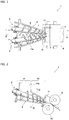
FIG. 2 ] A cross-sectional view of II-II inFIG. 1 and a longitudinal cross-sectional view of the extruder with roller-die in the embodiment of the present invention. - [
FIG. 3 ] A schematic cross-sectional view of a first screw side of a III-III cross-sectional view inFIG. 2 . - [
FIG. 4 ] A schematic cross-sectional view corresponding toFIG. 3 for explaining analysis conditions for a flow analysis. - [
FIG. 5 ] A schematic cross-sectional view corresponding toFIG. 3 for showing a modification of a flight thickening portion. - [
FIG. 6 ] A schematic cross-sectional view corresponding toFIG. 3 for showing a modification of a flight. - Hereinafter, embodiments for carrying out the present invention are described with reference to the drawings. The screw extruder shown in the following embodiment(s) is a screw extruder with roller-die (hereinafter, referred to as "extruder with roller-die) that extrudes a kneaded material of a high-polymer such as rubber and molds into a sheet form. The screw extruder in the present invention is also usable for a machine called pelletizer that extrudes a kneaded material of a high-polymer from a die having a multiplicity of circular holes, and then, cut it into cylindrical pellets.
- With reference to
FIG. 1 to FIG. 3 , an extruder with roller-die 1 in an embodiment of the present invention is described. The extruder with roller-die 1 includes two screws (afirst screw 2 and a second screw 3) that extrude a kneaded material and achamber 4 housing thescrews chamber 4, a pair of upper andlower rollers chamber 4 and therollers accumulation portion 11 where the kneaded material extruded by thescrews rollers rollers - The
chamber 4 includes a chamber upstreamportion 14 including, at the top, a kneadedmaterial supply port 14a and a chamberdownstream portion 24 having its periphery surrounded by a wall surface. The kneaded material such as rubber supplied to the kneadedmaterial supply port 14a from thereabove is extruded into theaccumulation portion 11 by thescrews rollers - The
screws first screw 2 and thesecond screw 3 are the same screws except that the torsion angles of the flights are opposite to each other, thefirst screw 2 is described as a representative. - The
first screw 2 includes ashaft portion 6 and ahelical flight 7 provided on the outer peripheral surface of theshaft portion 6. As shown inFIG. 3 , arib 8 as a flight thickening portion is provided at a part which is a tip portion of theflight 7 and is on the reverse side of the rotation direction R of theflight 7. An outerperipheral surface 7a of the tip portion of theflight 7 and an outerperipheral surface 8a of the tip portion of therib 8 are flush surfaces having no level difference therebetween, and are flush arc-shaped surfaces in the rotation direction R. Therib 8 may be fixed to the reverse surface of theflight 7 by welding or the like, or may be molded integrally with theflight 7. InFIG. 1 and FIG. 2 , illustration of therib 8 is omitted. - Here, as shown in
FIG. 3 , a part of aninner wall surface 4a of the chamber 4 (the chamber downstream portion 24) is an arc shape so that a uniform gap S is formed between the outerperipheral surface 7a of the tip portion of theflight 7 including therib 8 and the outerperipheral surface 8a. - Moreover, a
reverse surface 8b of therib 8 is a slanting surface so that the thickness of therib 8 continuously decreases toward the center O side of theshaft portion 6. - The rib 8 (the flight thickening portion) is continuously provided on the reverse surface of the
flight 7 in the rotation direction R, in a direction in which theflight 7 extends helically. That is, the rib 8 (the flight thickening portion) is a belt-like member having a shape shown inFIG. 3 in the cross-sectional shape. - The part of the
flight 7 where therib 8 is provided is disposed inside the chamberdownstream portion 24 the periphery of which is surrounded by the wall surface. Therib 8 may be provided on the reverse surface of the tip portion of also the part of theflight 7 disposed inside the chamberupstream portion 14. Further, therib 8 may be provided on the reverse surface of the tip portion of only the part of theflight 7 disposed inside the chamberupstream portion 14. - While the
flight 7 is a single flight from end to end in the axial direction in the embodiment shown inFIG. 1 and FIG. 2 , it is preferable that a part of theflight 7 that is inside the chamberdownstream portion 24 and where therib 8 is provided includes a plurality of flight portions, for example, two flight portions. - A two-dimensional flow analysis was performed for the
screw 2 where therib 8 as the flight thickening portion was provided at a part which was the tip portion of theflight 7 and was on the reverse side of the rotation direction R of theflight 7. - With reference to
FIG. 4 , the analysis conditions for the flow analysis are described below. First, not twin screws as described above, that is, the twoscrews screw 2 was housed in thechamber 4 that was circular in cross section. - The common analysis conditions were as follows:
- Inner diameter of the chamber 4: D mm
- Diameter of the
shaft portion 6 of the screw 2: 0.5D mm - Thickness T of the
flight 7 of the part where therib 8 is not provided: 0.05D mm - Number of rotations of the screw 2: 15 rpm
- Viscosity and density of the kneaded material: 1000 Pa·s and 1000 kg/m
- Regarding the flight in a comparative example (flight including, at the tip portion, no flight thickening portion) and also the flight in the present invention, the outer peripheral surface of the tip portion thereof (for the flight in the present invention, the rib portion was included) had a concentric arc shape along the arc of the
inner wall surface 4a of thechamber 4. - The gap S between the
flight 7 and theinner wall surface 4a of thechamber 4, the thickness W of the tip portion of theflight 7 and the filling ratio of the kneaded material inside thechamber 4 were changed, and the energy applied to the kneaded material was evaluated. The magnitude of the energy applied to the kneaded material was evaluated by the average rotation torque of thescrew 2 when thescrew 2 was rotated twice. The fact that the torque is high (or low) indicates that the energy applied to the kneaded material is high (or low). The analysis results are shown in Tables 1 and 2. In Tables 1 and 2, the average rotation torques of the flight under each of the conditions are represented by the ratio as the case where the average rotation torque when the gap S is 0.01 D and the filling ratio is 100% regarding the flight in the comparative example (the flight tip portion thickness W: 0.05 D) where the flight thickening portion is not provided at the tip portion is 1,000.Table 1 Filling ratio: 100% Gap S [mm] Thickness W of tip portion of flight [mm] Average rotation torque [-] 0.01D 0.05D 1.000 Comparative Example 0.01D 0.10D 1.060 0.01D 0.15D 1.167 Present Invention 0.01D 0.20D 1.250 0.02D 0.05D 0.838 Comparative Example 0.02D 0.10D 0.880 Present Invention 0.02D 0.15D 0.912 Table 2 Filling ratio: 90% Gap S [mm] Thickness W of tip portion of flight [mm] Average rotation torque [-] 0.01D 0.05D 0.856 Comparative Example 0.01D 0.10D 0.884 0.01D 0.15D 0.991 Present Invention 0.01D 0.20D 1.213 - As is apparent from Tables 1 and 2, the larger the thickness W of the tip portion of the
flight 7 is, the higher the average rotation torque (the energy applied to the kneaded material) is. From this, it is found that the dispersion mixing property of the kneaded material is improved by providing the rib 8 (the flight thickening portion) at the tip portion of the flight and increasing the thickness W of the tip portion of the flight. - Regarding the filling ratio of the kneaded material, from the comparison of analysis results when the gap S was 0.01D mm in Table 1 and Table 2, it is found that the higher the filling ratio is, the higher the energy applied to the kneaded material is. From this, the use of the
screw 2 where the thickness W of the tip portion of theflight 7 is large under the condition where the filling ratio of the kneaded material is high is more effective for improving the dispersion mixing property of the kneaded material. That is, the filling ratio of the kneaded material is higher in the chamberdownstream portion 24 having the periphery surrounded by the wall surface than in the chamberupstream portion 14 where the kneadedmaterial supply port 14a is provided. For this reason, as mentioned above, it is preferable that the part of theflight 7 where therib 8 is provided be disposed inside the chamberdownstream portion 24 having the periphery surrounded by the wall surface. - Further, by disposing the part of the
flight 7 where therib 8 is provided as having a plurality of flight portions (making the number of flights plural) inside the chamberdownstream portion 24 where the filling ratio of the kneaded material is high, the energy applied to the kneaded material can be made higher and the dispersion mixing property of the kneaded material can be further improved. - Moreover, from the above-described flow analysis results, it has been found that in a screw in the comparative example where the flight thickening portion is not provided on the reverse side of the tip portion of the flight, the kneaded material readily accumulates on the reverse side of the tip portion of the rotating flight. When the kneaded material accumulates, cooling of the kneaded material is inhibited, so that high temperature state continues for a long time. The continuation of the high temperature state causes deterioration of the kneaded material, so that kneading quality is degraded. From this, as in the above-described embodiment(s), by the provision, on the reverse side of the tip portion of the flight, of the rib 8 (flight thickening portion) having the thickness which continuously decreases toward the center side of the screw shaft, the accumulation of the kneaded material at this portion can be prevented. Thus, the deterioration of the kneaded material can be inhibited.
-
FIG. 5 shows a modification of the flight thickening portion. Therib 8 as the flight thickening portion shown inFIG. 3 and FIG. 4 is formed so that the thickness of therib 8 continuously decreases toward the center O side of theshaft portion 6 of the screw. Instead of this, it may be a rib with a substantially uniform thickness like a rib 12 (flight thickening portion) shown inFIG. 5 . -
FIG. 6 is a modification of the flight. The thickness of the flight 7 (flight body portion) shown inFIG. 3 to FIG. 5 is uniform from the base end portion which is the center O side portion of theshaft portion 6 toward the tip portion. Instead of this, it may be a flight that is thick at the base end portion and becomes thinner from the base end portion toward the tip portion like aflight 13 shown inFIG. 6 . In other words, it may be a flight that becomes thicker (increases in thickness) from the tip portion toward the base end portion. By adopting such a flight, the flight strength can be enhanced and the accumulation of the kneaded material between flights can be further prevented. - Moreover, while the outer peripheral surfaces of the tip portions of the
flights 7 including theribs FIG. 3, FIG. 4 andFIG. 5 are all arc-shaped in the rotation direction of theflights 7, they are not necessarily arc-shaped (the same applies to theflight 13 shown inFIG. 6 ). That is, the gap between the outer peripheral surface of the tip portion of the flight including the flight thickening portion and the inner wall surface of the chamber does not necessarily have uniform dimension. - While the
extruder 1 with roller-die shown inFIG. 1 and FIG. 2 is a screw extruder including twin screws, that is, thescrews - In addition, various modifications may be made within the scope that one of ordinary skill in the art can arrive at.
- As described above, the present invention is not limited to the above-described embodiment(s) but combining the structures of the embodiment(s) with each other, and modifications and applications by one of ordinary skill in the art based on the description of the specification and known art are also what the present invention targets and are embraced in the scope the protection of which is claimed.
- The present application is based upon Japanese Patent Application No.
2016-84212 filed on April 20, 2016 -
- 1:
- Extruder with roller-die (screw extruder)
- 2:
- First screw (screw)
- 3:
- Second screw (screw)
- 4:
- Chamber
- 4a:
- Inner wall surface
- 6:
- Shaft portion
- 7:
- Flight
- 8:
- Rib (flight thickening portion)
- 7a, 8a:
- Outer peripheral surface
- 9, 10:
- Roller
- 14:
- Chamber upstream portion
- 14a:
- Kneaded material supply port
- 24:
- Chamber downstream portion
- S:
- Gap
Claims (7)
- A screw extruder which extrudes a kneaded material, comprising:a screw having a helical flight provided on an outer peripheral surface of a shaft portion thereof; anda chamber housing the screw,wherein a flight thickening portion is provided at a part which is a tip portion of the flight and is on the reverse side of a rotation direction of the flight.
- The screw extruder according to claim 1, wherein:an outer peripheral surface of the tip portion where the flight thickening portion is provided is formed in an arc shape in the rotation direction of the flight; andat least a part of an inner wall surface of the chamber has an arc shape so that a gap having a uniform dimension is formed between the at least a part of an inner wall surface of the chamber and the outer peripheral surface of the tip portion including the flight thickening portion.
- The screw extruder according to claim 1 or 2,
wherein the flight thickening portion decreases in thickness toward a center side of the shaft portion. - The screw extruder according to claim 1 or 2,
wherein the chamber includes:a chamber upstream portion including, at a top portion thereof, a kneaded material supply port; anda chamber downstream portion having a periphery surrounded by a wall surface, andwherein the part including the flight thickening portion in the flight is disposed in the chamber downstream portion. - The screw extruder according to claim 3,
wherein the chamber includes:a chamber upstream portion including, at a top portion thereof, a kneaded material supply port; anda chamber downstream portion having a periphery surrounded by a wall surface, andwherein the part including the flight thickening portion in the flight is disposed in the chamber downstream portion. - The screw extruder according to claim 4,
wherein the part of the flight disposed in the chamber downstream portion comprises a plurality of flight portions. - The screw extruder according to claim 5,
wherein the part of the flight disposed in the chamber downstream portion comprises a plurality of flight portions.
Applications Claiming Priority (2)
| Application Number | Priority Date | Filing Date | Title |
|---|---|---|---|
| JP2016084212A JP6735135B2 (en) | 2016-04-20 | 2016-04-20 | Screw type extruder |
| PCT/JP2017/014930 WO2017183531A1 (en) | 2016-04-20 | 2017-04-12 | Screw-type extruder |
Publications (3)
| Publication Number | Publication Date |
|---|---|
| EP3446850A1 true EP3446850A1 (en) | 2019-02-27 |
| EP3446850A4 EP3446850A4 (en) | 2019-11-27 |
| EP3446850B1 EP3446850B1 (en) | 2021-06-02 |
Family
ID=60116857
Family Applications (1)
| Application Number | Title | Priority Date | Filing Date |
|---|---|---|---|
| EP17785870.1A Active EP3446850B1 (en) | 2016-04-20 | 2017-04-12 | Screw-type extruder |
Country Status (7)
| Country | Link |
|---|---|
| US (1) | US11027475B2 (en) |
| EP (1) | EP3446850B1 (en) |
| JP (1) | JP6735135B2 (en) |
| KR (1) | KR102139497B1 (en) |
| CN (1) | CN109070426B (en) |
| TW (1) | TWI671178B (en) |
| WO (1) | WO2017183531A1 (en) |
Families Citing this family (1)
| Publication number | Priority date | Publication date | Assignee | Title |
|---|---|---|---|---|
| JP2020029056A (en) * | 2018-08-23 | 2020-02-27 | 株式会社神戸製鋼所 | Screw |
Family Cites Families (19)
| Publication number | Priority date | Publication date | Assignee | Title |
|---|---|---|---|---|
| US3082816A (en) * | 1955-05-18 | 1963-03-26 | Welding Engineers | Process for treating material |
| DE7724432U1 (en) * | 1977-08-05 | 1977-11-10 | Bucher-Guyer Ag Maschinenfabrik, Niederweningen, Zuerich (Schweiz) | PLASTICIZING MACHINE FOR PROCESSING STRIP-SHAPED RAW MATERIAL |
| JPS5780037A (en) * | 1980-11-05 | 1982-05-19 | Mitsubishi Heavy Ind Ltd | High degree kneading type screw |
| JPS59124111U (en) | 1983-02-10 | 1984-08-21 | ピ−エイチ工業有限株式会社 | Composite resin kneading equipment |
| JPS63291632A (en) * | 1987-05-25 | 1988-11-29 | Mitsubishi Heavy Ind Ltd | Plasticized screw |
| CA2049256A1 (en) * | 1990-08-22 | 1992-02-23 | Masao Moriyama | Twin conical screw extruder |
| JPH0479623U (en) * | 1990-11-22 | 1992-07-10 | ||
| JPH09300433A (en) * | 1996-05-20 | 1997-11-25 | Kobe Steel Ltd | Screw for extruder |
| AT411663B (en) * | 2002-01-24 | 2004-04-26 | Cincinnati Extrusion Gmbh | SCREW EXTRUDERS |
| JP4255873B2 (en) * | 2004-03-30 | 2009-04-15 | 株式会社神戸製鋼所 | Conical twin screw extruder and dehydrator |
| US7513676B2 (en) * | 2004-05-08 | 2009-04-07 | Good Earth Tools, Inc. | Extruder screw with long wearing surfaces |
| ITMI20061694A1 (en) | 2006-09-06 | 2008-03-07 | Techint Spa | EXTRUDER WITH TWO CONVERGENT SCREWS FOR THE EXTRUSION OF PLASTOMERS, ELASTOMERS AND VISCOUS LIQUIDS IN GENERAL |
| JP4907366B2 (en) * | 2007-01-26 | 2012-03-28 | 株式会社神戸製鋼所 | Extruder screw, bearing segment used therefor, and twin screw extruder provided with extruder screw |
| ITPR20080068A1 (en) * | 2008-10-22 | 2010-04-23 | Storci S P A | COMPRESSION SCREW IN CONTINUOUS MACHINES FOR EXTRUSION AND PASTA PRODUCTION |
| JP5906793B2 (en) | 2012-02-20 | 2016-04-20 | 横浜ゴム株式会社 | Kneading system equipped with a closed rubber kneader |
| CN202573075U (en) | 2012-05-09 | 2012-12-05 | 湖北三盟机械制造有限公司 | Extrusion-type coal bar machine impellor |
| CN203637141U (en) * | 2013-10-31 | 2014-06-11 | 金发科技股份有限公司 | Thread element assembly applicable to double-screw extruder |
| JP6550253B2 (en) * | 2014-04-24 | 2019-07-24 | 東芝機械株式会社 | Screw for extruder, extruder and extrusion method |
| CN110171672B (en) * | 2019-04-09 | 2024-08-30 | 江西雷工机械科技有限公司 | Wear-resistant sheet, rotary drilling sheet, screw body and manufacturing method of screw body |
-
2016
- 2016-04-20 JP JP2016084212A patent/JP6735135B2/en not_active Expired - Fee Related
-
2017
- 2017-04-12 US US16/091,815 patent/US11027475B2/en not_active Expired - Fee Related
- 2017-04-12 KR KR1020187028801A patent/KR102139497B1/en not_active Expired - Fee Related
- 2017-04-12 CN CN201780024011.5A patent/CN109070426B/en not_active Expired - Fee Related
- 2017-04-12 WO PCT/JP2017/014930 patent/WO2017183531A1/en not_active Ceased
- 2017-04-12 EP EP17785870.1A patent/EP3446850B1/en active Active
- 2017-04-20 TW TW106113301A patent/TWI671178B/en not_active IP Right Cessation
Also Published As
| Publication number | Publication date |
|---|---|
| JP6735135B2 (en) | 2020-08-05 |
| US20190160722A1 (en) | 2019-05-30 |
| CN109070426B (en) | 2021-09-03 |
| TW201801891A (en) | 2018-01-16 |
| CN109070426A (en) | 2018-12-21 |
| EP3446850A4 (en) | 2019-11-27 |
| JP2017193097A (en) | 2017-10-26 |
| TWI671178B (en) | 2019-09-11 |
| US11027475B2 (en) | 2021-06-08 |
| WO2017183531A1 (en) | 2017-10-26 |
| EP3446850B1 (en) | 2021-06-02 |
| KR102139497B1 (en) | 2020-07-30 |
| KR20180120740A (en) | 2018-11-06 |
Similar Documents
| Publication | Publication Date | Title |
|---|---|---|
| EP3915758B1 (en) | Screw and pin-type extruder | |
| EP2093037B1 (en) | Kneading disc segment and twin-screw extruder | |
| US10532492B2 (en) | Twin-screw extruder including variable diameter of screws and barrel and kneading method using the twin-screw extruder including variable diameter of screws and barrel | |
| US9085093B2 (en) | Screw segment | |
| EP2168743B1 (en) | Melting kneading devolatilizing extruder | |
| CN1721157A (en) | extruder | |
| JP4555351B2 (en) | Kneading degree adjusting device, extruder, and continuous kneader | |
| JP2008183721A (en) | Extruder screw, bearing segment used for this screw, and biaxial extruder equipped with this screw | |
| JP6754018B1 (en) | Screws, extruders and extrusion methods | |
| EP1768823B1 (en) | Apparatus for plasticating thermoplastic resin including polypropylene | |
| CN101400500B (en) | Screw element | |
| EP3446850B1 (en) | Screw-type extruder | |
| CA2057603C (en) | Extruder for poorly miscible extrudates | |
| JP2005001231A (en) | Rubber continuous kneading extruder | |
| KR102261450B1 (en) | screw extruder | |
| WO2019031350A1 (en) | Screw extruder with rollers | |
| JPH0691726A (en) | Series two-stage extruder | |
| EP3797967A1 (en) | Screw-type extruder | |
| JP3598072B2 (en) | Kneading ring and screw type kneading extruder | |
| EP3501784B1 (en) | Method for supplying material to extruder | |
| JP2002292719A (en) | Extruder, method for extruding thermoplastic resin using the same, and method for removing volatile components |
Legal Events
| Date | Code | Title | Description |
|---|---|---|---|
| STAA | Information on the status of an ep patent application or granted ep patent |
Free format text: STATUS: THE INTERNATIONAL PUBLICATION HAS BEEN MADE |
|
| PUAI | Public reference made under article 153(3) epc to a published international application that has entered the european phase |
Free format text: ORIGINAL CODE: 0009012 |
|
| STAA | Information on the status of an ep patent application or granted ep patent |
Free format text: STATUS: REQUEST FOR EXAMINATION WAS MADE |
|
| 17P | Request for examination filed |
Effective date: 20181018 |
|
| AK | Designated contracting states |
Kind code of ref document: A1 Designated state(s): AL AT BE BG CH CY CZ DE DK EE ES FI FR GB GR HR HU IE IS IT LI LT LU LV MC MK MT NL NO PL PT RO RS SE SI SK SM TR |
|
| AX | Request for extension of the european patent |
Extension state: BA ME |
|
| DAV | Request for validation of the european patent (deleted) | ||
| DAX | Request for extension of the european patent (deleted) | ||
| A4 | Supplementary search report drawn up and despatched |
Effective date: 20191029 |
|
| RIC1 | Information provided on ipc code assigned before grant |
Ipc: B29B 7/48 20060101ALN20191023BHEP Ipc: B29C 48/60 20190101AFI20191023BHEP Ipc: B29C 48/395 20190101ALI20191023BHEP Ipc: B29C 48/80 20190101ALI20191023BHEP Ipc: B29C 48/505 20190101ALI20191023BHEP Ipc: B29B 7/74 20060101ALN20191023BHEP |
|
| STAA | Information on the status of an ep patent application or granted ep patent |
Free format text: STATUS: EXAMINATION IS IN PROGRESS |
|
| 17Q | First examination report despatched |
Effective date: 20200810 |
|
| REG | Reference to a national code |
Ref country code: DE Ref legal event code: R079 Ref document number: 602017039737 Country of ref document: DE Free format text: PREVIOUS MAIN CLASS: B29C0047600000 Ipc: B29C0048600000 |
|
| GRAP | Despatch of communication of intention to grant a patent |
Free format text: ORIGINAL CODE: EPIDOSNIGR1 |
|
| STAA | Information on the status of an ep patent application or granted ep patent |
Free format text: STATUS: GRANT OF PATENT IS INTENDED |
|
| RIC1 | Information provided on ipc code assigned before grant |
Ipc: B29B 7/48 20060101ALI20210208BHEP Ipc: B29C 48/395 20190101ALI20210208BHEP Ipc: B29C 48/52 20190101ALN20210208BHEP Ipc: B29B 7/74 20060101ALI20210208BHEP Ipc: B29B 7/52 20060101ALI20210208BHEP Ipc: B29K 21/00 20060101ALN20210208BHEP Ipc: B29C 48/38 20190101ALN20210208BHEP Ipc: B29C 48/59 20190101ALN20210208BHEP Ipc: B29C 48/60 20190101AFI20210208BHEP Ipc: B29C 48/35 20190101ALN20210208BHEP |
|
| INTG | Intention to grant announced |
Effective date: 20210226 |
|
| GRAS | Grant fee paid |
Free format text: ORIGINAL CODE: EPIDOSNIGR3 |
|
| GRAA | (expected) grant |
Free format text: ORIGINAL CODE: 0009210 |
|
| STAA | Information on the status of an ep patent application or granted ep patent |
Free format text: STATUS: THE PATENT HAS BEEN GRANTED |
|
| REG | Reference to a national code |
Ref country code: CH Ref legal event code: EP |
|
| AK | Designated contracting states |
Kind code of ref document: B1 Designated state(s): AL AT BE BG CH CY CZ DE DK EE ES FI FR GB GR HR HU IE IS IT LI LT LU LV MC MK MT NL NO PL PT RO RS SE SI SK SM TR |
|
| REG | Reference to a national code |
Ref country code: GB Ref legal event code: FG4D |
|
| REG | Reference to a national code |
Ref country code: AT Ref legal event code: REF Ref document number: 1398020 Country of ref document: AT Kind code of ref document: T Effective date: 20210615 |
|
| REG | Reference to a national code |
Ref country code: IE Ref legal event code: FG4D |
|
| REG | Reference to a national code |
Ref country code: DE Ref legal event code: R096 Ref document number: 602017039737 Country of ref document: DE |
|
| REG | Reference to a national code |
Ref country code: LT Ref legal event code: MG9D |
|
| PG25 | Lapsed in a contracting state [announced via postgrant information from national office to epo] |
Ref country code: FI Free format text: LAPSE BECAUSE OF FAILURE TO SUBMIT A TRANSLATION OF THE DESCRIPTION OR TO PAY THE FEE WITHIN THE PRESCRIBED TIME-LIMIT Effective date: 20210602 Ref country code: LT Free format text: LAPSE BECAUSE OF FAILURE TO SUBMIT A TRANSLATION OF THE DESCRIPTION OR TO PAY THE FEE WITHIN THE PRESCRIBED TIME-LIMIT Effective date: 20210602 Ref country code: HR Free format text: LAPSE BECAUSE OF FAILURE TO SUBMIT A TRANSLATION OF THE DESCRIPTION OR TO PAY THE FEE WITHIN THE PRESCRIBED TIME-LIMIT Effective date: 20210602 Ref country code: BG Free format text: LAPSE BECAUSE OF FAILURE TO SUBMIT A TRANSLATION OF THE DESCRIPTION OR TO PAY THE FEE WITHIN THE PRESCRIBED TIME-LIMIT Effective date: 20210902 |
|
| REG | Reference to a national code |
Ref country code: NL Ref legal event code: MP Effective date: 20210602 |
|
| REG | Reference to a national code |
Ref country code: AT Ref legal event code: MK05 Ref document number: 1398020 Country of ref document: AT Kind code of ref document: T Effective date: 20210602 |
|
| PG25 | Lapsed in a contracting state [announced via postgrant information from national office to epo] |
Ref country code: GR Free format text: LAPSE BECAUSE OF FAILURE TO SUBMIT A TRANSLATION OF THE DESCRIPTION OR TO PAY THE FEE WITHIN THE PRESCRIBED TIME-LIMIT Effective date: 20210903 Ref country code: NO Free format text: LAPSE BECAUSE OF FAILURE TO SUBMIT A TRANSLATION OF THE DESCRIPTION OR TO PAY THE FEE WITHIN THE PRESCRIBED TIME-LIMIT Effective date: 20210902 Ref country code: LV Free format text: LAPSE BECAUSE OF FAILURE TO SUBMIT A TRANSLATION OF THE DESCRIPTION OR TO PAY THE FEE WITHIN THE PRESCRIBED TIME-LIMIT Effective date: 20210602 Ref country code: PL Free format text: LAPSE BECAUSE OF FAILURE TO SUBMIT A TRANSLATION OF THE DESCRIPTION OR TO PAY THE FEE WITHIN THE PRESCRIBED TIME-LIMIT Effective date: 20210602 Ref country code: SE Free format text: LAPSE BECAUSE OF FAILURE TO SUBMIT A TRANSLATION OF THE DESCRIPTION OR TO PAY THE FEE WITHIN THE PRESCRIBED TIME-LIMIT Effective date: 20210602 Ref country code: RS Free format text: LAPSE BECAUSE OF FAILURE TO SUBMIT A TRANSLATION OF THE DESCRIPTION OR TO PAY THE FEE WITHIN THE PRESCRIBED TIME-LIMIT Effective date: 20210602 |
|
| PG25 | Lapsed in a contracting state [announced via postgrant information from national office to epo] |
Ref country code: AT Free format text: LAPSE BECAUSE OF FAILURE TO SUBMIT A TRANSLATION OF THE DESCRIPTION OR TO PAY THE FEE WITHIN THE PRESCRIBED TIME-LIMIT Effective date: 20210602 Ref country code: EE Free format text: LAPSE BECAUSE OF FAILURE TO SUBMIT A TRANSLATION OF THE DESCRIPTION OR TO PAY THE FEE WITHIN THE PRESCRIBED TIME-LIMIT Effective date: 20210602 Ref country code: CZ Free format text: LAPSE BECAUSE OF FAILURE TO SUBMIT A TRANSLATION OF THE DESCRIPTION OR TO PAY THE FEE WITHIN THE PRESCRIBED TIME-LIMIT Effective date: 20210602 Ref country code: PT Free format text: LAPSE BECAUSE OF FAILURE TO SUBMIT A TRANSLATION OF THE DESCRIPTION OR TO PAY THE FEE WITHIN THE PRESCRIBED TIME-LIMIT Effective date: 20211004 Ref country code: NL Free format text: LAPSE BECAUSE OF FAILURE TO SUBMIT A TRANSLATION OF THE DESCRIPTION OR TO PAY THE FEE WITHIN THE PRESCRIBED TIME-LIMIT Effective date: 20210602 Ref country code: RO Free format text: LAPSE BECAUSE OF FAILURE TO SUBMIT A TRANSLATION OF THE DESCRIPTION OR TO PAY THE FEE WITHIN THE PRESCRIBED TIME-LIMIT Effective date: 20210602 Ref country code: ES Free format text: LAPSE BECAUSE OF FAILURE TO SUBMIT A TRANSLATION OF THE DESCRIPTION OR TO PAY THE FEE WITHIN THE PRESCRIBED TIME-LIMIT Effective date: 20210602 Ref country code: SM Free format text: LAPSE BECAUSE OF FAILURE TO SUBMIT A TRANSLATION OF THE DESCRIPTION OR TO PAY THE FEE WITHIN THE PRESCRIBED TIME-LIMIT Effective date: 20210602 Ref country code: SK Free format text: LAPSE BECAUSE OF FAILURE TO SUBMIT A TRANSLATION OF THE DESCRIPTION OR TO PAY THE FEE WITHIN THE PRESCRIBED TIME-LIMIT Effective date: 20210602 |
|
| REG | Reference to a national code |
Ref country code: DE Ref legal event code: R097 Ref document number: 602017039737 Country of ref document: DE |
|
| PLBE | No opposition filed within time limit |
Free format text: ORIGINAL CODE: 0009261 |
|
| STAA | Information on the status of an ep patent application or granted ep patent |
Free format text: STATUS: NO OPPOSITION FILED WITHIN TIME LIMIT |
|
| PG25 | Lapsed in a contracting state [announced via postgrant information from national office to epo] |
Ref country code: DK Free format text: LAPSE BECAUSE OF FAILURE TO SUBMIT A TRANSLATION OF THE DESCRIPTION OR TO PAY THE FEE WITHIN THE PRESCRIBED TIME-LIMIT Effective date: 20210602 |
|
| 26N | No opposition filed |
Effective date: 20220303 |
|
| PG25 | Lapsed in a contracting state [announced via postgrant information from national office to epo] |
Ref country code: AL Free format text: LAPSE BECAUSE OF FAILURE TO SUBMIT A TRANSLATION OF THE DESCRIPTION OR TO PAY THE FEE WITHIN THE PRESCRIBED TIME-LIMIT Effective date: 20210602 |
|
| REG | Reference to a national code |
Ref country code: CH Ref legal event code: PL |
|
| REG | Reference to a national code |
Ref country code: BE Ref legal event code: MM Effective date: 20220430 |
|
| PG25 | Lapsed in a contracting state [announced via postgrant information from national office to epo] |
Ref country code: MC Free format text: LAPSE BECAUSE OF FAILURE TO SUBMIT A TRANSLATION OF THE DESCRIPTION OR TO PAY THE FEE WITHIN THE PRESCRIBED TIME-LIMIT Effective date: 20210602 Ref country code: LU Free format text: LAPSE BECAUSE OF NON-PAYMENT OF DUE FEES Effective date: 20220412 Ref country code: LI Free format text: LAPSE BECAUSE OF NON-PAYMENT OF DUE FEES Effective date: 20220430 Ref country code: FR Free format text: LAPSE BECAUSE OF NON-PAYMENT OF DUE FEES Effective date: 20220430 Ref country code: CH Free format text: LAPSE BECAUSE OF NON-PAYMENT OF DUE FEES Effective date: 20220430 |
|
| PG25 | Lapsed in a contracting state [announced via postgrant information from national office to epo] |
Ref country code: BE Free format text: LAPSE BECAUSE OF NON-PAYMENT OF DUE FEES Effective date: 20220430 |
|
| PG25 | Lapsed in a contracting state [announced via postgrant information from national office to epo] |
Ref country code: IE Free format text: LAPSE BECAUSE OF NON-PAYMENT OF DUE FEES Effective date: 20220412 |
|
| PGFP | Annual fee paid to national office [announced via postgrant information from national office to epo] |
Ref country code: IT Payment date: 20230310 Year of fee payment: 7 |
|
| P01 | Opt-out of the competence of the unified patent court (upc) registered |
Effective date: 20230523 |
|
| PG25 | Lapsed in a contracting state [announced via postgrant information from national office to epo] |
Ref country code: HU Free format text: LAPSE BECAUSE OF FAILURE TO SUBMIT A TRANSLATION OF THE DESCRIPTION OR TO PAY THE FEE WITHIN THE PRESCRIBED TIME-LIMIT; INVALID AB INITIO Effective date: 20170412 |
|
| PG25 | Lapsed in a contracting state [announced via postgrant information from national office to epo] |
Ref country code: MK Free format text: LAPSE BECAUSE OF FAILURE TO SUBMIT A TRANSLATION OF THE DESCRIPTION OR TO PAY THE FEE WITHIN THE PRESCRIBED TIME-LIMIT Effective date: 20210602 Ref country code: CY Free format text: LAPSE BECAUSE OF FAILURE TO SUBMIT A TRANSLATION OF THE DESCRIPTION OR TO PAY THE FEE WITHIN THE PRESCRIBED TIME-LIMIT Effective date: 20210602 |
|
| PGFP | Annual fee paid to national office [announced via postgrant information from national office to epo] |
Ref country code: GB Payment date: 20240229 Year of fee payment: 8 |
|
| PG25 | Lapsed in a contracting state [announced via postgrant information from national office to epo] |
Ref country code: TR Free format text: LAPSE BECAUSE OF FAILURE TO SUBMIT A TRANSLATION OF THE DESCRIPTION OR TO PAY THE FEE WITHIN THE PRESCRIBED TIME-LIMIT Effective date: 20210602 |
|
| PGFP | Annual fee paid to national office [announced via postgrant information from national office to epo] |
Ref country code: DE Payment date: 20240227 Year of fee payment: 8 |
|
| PG25 | Lapsed in a contracting state [announced via postgrant information from national office to epo] |
Ref country code: MT Free format text: LAPSE BECAUSE OF FAILURE TO SUBMIT A TRANSLATION OF THE DESCRIPTION OR TO PAY THE FEE WITHIN THE PRESCRIBED TIME-LIMIT Effective date: 20210602 |
|
| PG25 | Lapsed in a contracting state [announced via postgrant information from national office to epo] |
Ref country code: IT Free format text: LAPSE BECAUSE OF NON-PAYMENT OF DUE FEES Effective date: 20240412 |
|
| REG | Reference to a national code |
Ref country code: DE Ref legal event code: R119 Ref document number: 602017039737 Country of ref document: DE |
|
| GBPC | Gb: european patent ceased through non-payment of renewal fee |
Effective date: 20250412 |
|
| PG25 | Lapsed in a contracting state [announced via postgrant information from national office to epo] |
Ref country code: DE Free format text: LAPSE BECAUSE OF NON-PAYMENT OF DUE FEES Effective date: 20251104 |
|
| PG25 | Lapsed in a contracting state [announced via postgrant information from national office to epo] |
Ref country code: GB Free format text: LAPSE BECAUSE OF NON-PAYMENT OF DUE FEES Effective date: 20250412 |