EP3446750B1 - Laser irradiation apparatus using robot arm - Google Patents
Laser irradiation apparatus using robot arm Download PDFInfo
- Publication number
- EP3446750B1 EP3446750B1 EP17786094.7A EP17786094A EP3446750B1 EP 3446750 B1 EP3446750 B1 EP 3446750B1 EP 17786094 A EP17786094 A EP 17786094A EP 3446750 B1 EP3446750 B1 EP 3446750B1
- Authority
- EP
- European Patent Office
- Prior art keywords
- region
- laser
- therapy
- link
- robot arm
- Prior art date
- Legal status (The legal status is an assumption and is not a legal conclusion. Google has not performed a legal analysis and makes no representation as to the accuracy of the status listed.)
- Active
Links
- 238000002560 therapeutic procedure Methods 0.000 claims description 78
- 230000033001 locomotion Effects 0.000 claims description 41
- 239000012636 effector Substances 0.000 claims description 30
- 238000011282 treatment Methods 0.000 claims description 21
- 238000000034 method Methods 0.000 claims description 18
- 230000001678 irradiating effect Effects 0.000 claims description 17
- 238000013532 laser treatment Methods 0.000 description 13
- 230000001133 acceleration Effects 0.000 description 10
- 230000003247 decreasing effect Effects 0.000 description 4
- 210000003128 head Anatomy 0.000 description 4
- 238000013475 authorization Methods 0.000 description 3
- 239000011505 plaster Substances 0.000 description 3
- 231100000241 scar Toxicity 0.000 description 3
- 238000013459 approach Methods 0.000 description 2
- 210000004204 blood vessel Anatomy 0.000 description 2
- 238000010276 construction Methods 0.000 description 2
- 238000010586 diagram Methods 0.000 description 2
- 230000000694 effects Effects 0.000 description 2
- 230000001815 facial effect Effects 0.000 description 2
- 239000011159 matrix material Substances 0.000 description 2
- 239000000049 pigment Substances 0.000 description 2
- 230000001225 therapeutic effect Effects 0.000 description 2
- 230000037303 wrinkles Effects 0.000 description 2
- 208000002874 Acne Vulgaris Diseases 0.000 description 1
- 201000004384 Alopecia Diseases 0.000 description 1
- 206010003694 Atrophy Diseases 0.000 description 1
- 208000032544 Cicatrix Diseases 0.000 description 1
- 206010010904 Convulsion Diseases 0.000 description 1
- 206010014970 Ephelides Diseases 0.000 description 1
- 208000003351 Melanosis Diseases 0.000 description 1
- 241001085205 Prenanthella exigua Species 0.000 description 1
- 206010064127 Solar lentigo Diseases 0.000 description 1
- 206010043189 Telangiectasia Diseases 0.000 description 1
- 206010000496 acne Diseases 0.000 description 1
- 238000013473 artificial intelligence Methods 0.000 description 1
- 230000037444 atrophy Effects 0.000 description 1
- 230000005540 biological transmission Effects 0.000 description 1
- 239000003638 chemical reducing agent Substances 0.000 description 1
- 238000004590 computer program Methods 0.000 description 1
- 230000036461 convulsion Effects 0.000 description 1
- 238000013500 data storage Methods 0.000 description 1
- 230000001419 dependent effect Effects 0.000 description 1
- 238000003745 diagnosis Methods 0.000 description 1
- 238000002474 experimental method Methods 0.000 description 1
- 239000000945 filler Substances 0.000 description 1
- 230000003779 hair growth Effects 0.000 description 1
- 208000024963 hair loss Diseases 0.000 description 1
- 230000003676 hair loss Effects 0.000 description 1
- 239000007943 implant Substances 0.000 description 1
- 238000005259 measurement Methods 0.000 description 1
- 230000003287 optical effect Effects 0.000 description 1
- 239000013307 optical fiber Substances 0.000 description 1
- 239000011148 porous material Substances 0.000 description 1
- 238000012545 processing Methods 0.000 description 1
- 230000037387 scars Effects 0.000 description 1
- 230000009759 skin aging Effects 0.000 description 1
- 230000036560 skin regeneration Effects 0.000 description 1
- 210000004003 subcutaneous fat Anatomy 0.000 description 1
- 208000009056 telangiectasis Diseases 0.000 description 1
- 238000002604 ultrasonography Methods 0.000 description 1
- 230000002087 whitening effect Effects 0.000 description 1
Images


Classifications
-
- A—HUMAN NECESSITIES
- A61—MEDICAL OR VETERINARY SCIENCE; HYGIENE
- A61B—DIAGNOSIS; SURGERY; IDENTIFICATION
- A61B18/00—Surgical instruments, devices or methods for transferring non-mechanical forms of energy to or from the body
- A61B18/18—Surgical instruments, devices or methods for transferring non-mechanical forms of energy to or from the body by applying electromagnetic radiation, e.g. microwaves
- A61B18/20—Surgical instruments, devices or methods for transferring non-mechanical forms of energy to or from the body by applying electromagnetic radiation, e.g. microwaves using laser
- A61B18/203—Surgical instruments, devices or methods for transferring non-mechanical forms of energy to or from the body by applying electromagnetic radiation, e.g. microwaves using laser applying laser energy to the outside of the body
-
- A—HUMAN NECESSITIES
- A61—MEDICAL OR VETERINARY SCIENCE; HYGIENE
- A61B—DIAGNOSIS; SURGERY; IDENTIFICATION
- A61B18/00—Surgical instruments, devices or methods for transferring non-mechanical forms of energy to or from the body
- A61B18/18—Surgical instruments, devices or methods for transferring non-mechanical forms of energy to or from the body by applying electromagnetic radiation, e.g. microwaves
- A61B18/20—Surgical instruments, devices or methods for transferring non-mechanical forms of energy to or from the body by applying electromagnetic radiation, e.g. microwaves using laser
- A61B18/201—Surgical instruments, devices or methods for transferring non-mechanical forms of energy to or from the body by applying electromagnetic radiation, e.g. microwaves using laser with beam delivery through a hollow tube, e.g. forming an articulated arm ; Hand-pieces therefor
-
- A—HUMAN NECESSITIES
- A61—MEDICAL OR VETERINARY SCIENCE; HYGIENE
- A61B—DIAGNOSIS; SURGERY; IDENTIFICATION
- A61B34/00—Computer-aided surgery; Manipulators or robots specially adapted for use in surgery
- A61B34/30—Surgical robots
-
- A—HUMAN NECESSITIES
- A61—MEDICAL OR VETERINARY SCIENCE; HYGIENE
- A61B—DIAGNOSIS; SURGERY; IDENTIFICATION
- A61B5/00—Measuring for diagnostic purposes; Identification of persons
- A61B5/0059—Measuring for diagnostic purposes; Identification of persons using light, e.g. diagnosis by transillumination, diascopy, fluorescence
- A61B5/0062—Arrangements for scanning
- A61B5/0064—Body surface scanning
-
- A—HUMAN NECESSITIES
- A61—MEDICAL OR VETERINARY SCIENCE; HYGIENE
- A61N—ELECTROTHERAPY; MAGNETOTHERAPY; RADIATION THERAPY; ULTRASOUND THERAPY
- A61N5/00—Radiation therapy
- A61N5/06—Radiation therapy using light
-
- A—HUMAN NECESSITIES
- A61—MEDICAL OR VETERINARY SCIENCE; HYGIENE
- A61N—ELECTROTHERAPY; MAGNETOTHERAPY; RADIATION THERAPY; ULTRASOUND THERAPY
- A61N5/00—Radiation therapy
- A61N5/06—Radiation therapy using light
- A61N5/0613—Apparatus adapted for a specific treatment
- A61N5/0616—Skin treatment other than tanning
-
- A—HUMAN NECESSITIES
- A61—MEDICAL OR VETERINARY SCIENCE; HYGIENE
- A61N—ELECTROTHERAPY; MAGNETOTHERAPY; RADIATION THERAPY; ULTRASOUND THERAPY
- A61N5/00—Radiation therapy
- A61N5/06—Radiation therapy using light
- A61N5/067—Radiation therapy using light using laser light
-
- A—HUMAN NECESSITIES
- A61—MEDICAL OR VETERINARY SCIENCE; HYGIENE
- A61B—DIAGNOSIS; SURGERY; IDENTIFICATION
- A61B18/00—Surgical instruments, devices or methods for transferring non-mechanical forms of energy to or from the body
- A61B2018/00315—Surgical instruments, devices or methods for transferring non-mechanical forms of energy to or from the body for treatment of particular body parts
- A61B2018/00452—Skin
-
- A—HUMAN NECESSITIES
- A61—MEDICAL OR VETERINARY SCIENCE; HYGIENE
- A61B—DIAGNOSIS; SURGERY; IDENTIFICATION
- A61B18/00—Surgical instruments, devices or methods for transferring non-mechanical forms of energy to or from the body
- A61B2018/00636—Sensing and controlling the application of energy
- A61B2018/00904—Automatic detection of target tissue
-
- A—HUMAN NECESSITIES
- A61—MEDICAL OR VETERINARY SCIENCE; HYGIENE
- A61B—DIAGNOSIS; SURGERY; IDENTIFICATION
- A61B18/00—Surgical instruments, devices or methods for transferring non-mechanical forms of energy to or from the body
- A61B18/18—Surgical instruments, devices or methods for transferring non-mechanical forms of energy to or from the body by applying electromagnetic radiation, e.g. microwaves
- A61B2018/1807—Surgical instruments, devices or methods for transferring non-mechanical forms of energy to or from the body by applying electromagnetic radiation, e.g. microwaves using light other than laser radiation
-
- A—HUMAN NECESSITIES
- A61—MEDICAL OR VETERINARY SCIENCE; HYGIENE
- A61B—DIAGNOSIS; SURGERY; IDENTIFICATION
- A61B90/00—Instruments, implements or accessories specially adapted for surgery or diagnosis and not covered by any of the groups A61B1/00 - A61B50/00, e.g. for luxation treatment or for protecting wound edges
- A61B90/36—Image-producing devices or illumination devices not otherwise provided for
- A61B90/361—Image-producing devices, e.g. surgical cameras
- A61B2090/3612—Image-producing devices, e.g. surgical cameras with images taken automatically
-
- A—HUMAN NECESSITIES
- A61—MEDICAL OR VETERINARY SCIENCE; HYGIENE
- A61B—DIAGNOSIS; SURGERY; IDENTIFICATION
- A61B5/00—Measuring for diagnostic purposes; Identification of persons
- A61B5/44—Detecting, measuring or recording for evaluating the integumentary system, e.g. skin, hair or nails
- A61B5/441—Skin evaluation, e.g. for skin disorder diagnosis
-
- A—HUMAN NECESSITIES
- A61—MEDICAL OR VETERINARY SCIENCE; HYGIENE
- A61N—ELECTROTHERAPY; MAGNETOTHERAPY; RADIATION THERAPY; ULTRASOUND THERAPY
- A61N5/00—Radiation therapy
- A61N5/06—Radiation therapy using light
- A61N2005/0635—Radiation therapy using light characterised by the body area to be irradiated
- A61N2005/0643—Applicators, probes irradiating specific body areas in close proximity
Description
- The present invention relates to a laser irradiation apparatus using a robot arm.
- Today, a variety of laser treatment methods by irradiating the laser beam on the skin have been developed to achieve the purpose of treatment, etc., and have been still actively studying a medical laser apparatus for use the laser treatment methods.
- The treatment methods using the laser has been using for a variety of purposes such as to promote hair growth or prevent hair loss, skin peel, skin regeneration, skin whitening, wrinkle or spot removal, or stain removal, etc.
- However, a user, such as a physician, manually operates the laser treatment apparatus to perform the treatment in the conventional art.
- Accordingly, there is a problem in that the reliability of the treatment may be decreased by lowering the accuracy of the treatment.
- In addition, conventionally, there is an additional problem that of the treatment time for taking the laser is excessively too long Reference is made to the following documents related to image-guided laser treatments:
US2008/0033410 A1 ,US2015/0057675 A1 ,US2005/09137584 A1 US2008/0247637 A1 andUS 2016/0016312 A1 . - An object of the present invention is to provide a laser irradiation apparatus using a robot arm according to
claim 1, which can automatically scan an object and irradiate with the laser beam on the surface of the object based on the scanned information. Further embodiments of the present invention are described in the dependent claims. A method thereof is additionally provided as an example. - The example laser irradiation method using a robot arm includes collecting a raw data by scanning an object; constituting a three-dimensional image of the object on the basis of the raw data; setting a region of interest (ROI) on a surface of the object in the three-dimensional image; setting a guide path passing through the region of interest; and irradiating a laser on the surface of the object corresponding to the guide path using the robot arm having an end-effector.
- On the other hand, the example laser irradiation method is making a computer program for performing him may be provided in the program itself or stored in a recording medium, it can be performed by the laser irradiation apparatus according to an embodiment of the present invention.
- The laser irradiation apparatus using a robot arm in accordance with the claimed invention includes a scanner for scanning an object to collect a raw data; a vision controlling unit for constituting a three-dimensional image of the object on the basis of the raw data, and setting a region of interest (ROI) on the surface of the object in the three-dimensional image; a motion controlling unit for setting a guide path passing through the region of interest; and a robot arm, having an end-effector, for irradiating a laser on the surface of the object corresponding to the guide path.
- In addition, the laser irradiation apparatus may use a wired or wireless network such as the Internet may be controlled as described above in conjunction with an external server.
- In addition, the robot arm comprises a first base part; a second base part being coupled to be rotatable on the first base part; a first link being coupled to be rotatable on the second base part; a second link being coupled to be rotatable on the first link; an auxiliary link having one end coupled to the second base part and the other end coupled to the second link; a laser unit, arranged on the first base part, for generating the laser; a first motor part, arranged on the first base part, for rotating the second base part; a second motor part, arranged on the second base part, for rotating the first link; and a third motor part, arranged on the second base part, for rotating the second link through the auxiliary link.
- A laser irradiation apparatus using a robot arm according to the present invention has effects that of improving the accuracy of the laser treatment and effectively reducing the operational time required for the laser treatment.
- The accompanying drawings, which are included to provide a further understanding of the invention and are incorporated in and constitute a part of this specification, illustrate embodiments of the invention and together with the description serve to explain the principles of the invention.
-
Figs. 1 to 3 are block diagrams for explaining embodiments for the overall structure of a laser irradiation apparatus according to the present invention. -
Figs. 4 to 25 are views for explaining the operation of a laser irradiation apparatus according to the present invention. -
Figs. 26 to 34 are views for explaining embodiments of a structure of a robot arm according to the present invention. - Detailed exemplary embodiments of the present invention will be described with reference to the accompanying drawings.
- The present invention may be modified in various ways and implemented by various exemplary embodiments, so that specific exemplary embodiments are illustrated in the drawings and will be described in detail below. However, it is to be understood that the present invention is not limited to the specific exemplary embodiments.
- On the other hand, although the first and / or the terms of the second and so on in the present invention can be used in describing various elements, but the above elements shall not be restricted to the above terms. These terms are only to distinguish one component from other components, for example within that range departing from the scope of the concept of the present invention, a first element could be termed a second element, Similarly, the second component may be named as a first component.
- As used herein, the term "and/or" includes any and all combinations of one or more of the associated listed items.
- It will be understood that when an element is referred to as being "connected" or "coupled" to another element, it can be directly connected or coupled to the other element or intervening elements may be present. In contrast, it will be understood that when an element is referred to as being "directly connected" or "directly coupled" to another element, there are no intervening elements present.
- The terminology used herein is for the purpose of describing particular embodiments only and is not intended to be limiting of the invention. As used herein, the singular forms are intended to include the plural forms as well, unless the context clearly indicates otherwise.
- It will be further understood that the terms "comprises," "comprising," "includes," and/or "including," when used herein, specify the presence of stated features, integers, steps, operations, elements, and/or components, but do not preclude the presence or addition of one or more other features, integers, steps, operations, elements, components, and/or groups thereof.
- Unless otherwise defined, all terms used herein have the same meaning as commonly understood by one of ordinary skill in the art to which this invention belongs. It will be further understood that terms, such as those defined in commonly used dictionaries, should be interpreted as having a meaning that is consistent with their meaning in the context of the relevant art and will not be interpreted in an idealized or overly formal sense unless expressly so defined herein.
- The accompanying drawings are intended to illustrate aspects of the present invention, but the scope of the present invention is not limited to this. In addition, the attached drawings will be noted that the portion or component is disposed is enlarged / reduced to better explain the characteristics of the present invention.
- In the following description, it is explained as an example that the laser is irradiated to the facial skin of a patient for ease of explanation, but an apparatus and a method relating to the present invention may be applied whatever as long as irradiating the laser on the surface of a given object.
- Hereinafter, a laser irradiation apparatus using a robot arm and a method relating to the present invention is described in detail with reference to the accompanying drawings.
-
Figs. 1 to 3 are block diagrams for explaining embodiments for the overall structure of the laser irradiation apparatus according to the present invention. - Referring to
Fig.1 , thelaser irradiation apparatus 10 may include ascanner 300, arobot arm 100, and a controllingunit 200. - The
scanner 300 may collect raw data by scanning an object. Here, the raw data may include two-dimensional image and depth information. - The two-dimensional image may include color information, the diagnosis of the particular condition, such as telangiectasia may be possible according to the color information of a patient's skin. Further, the scanner may detect the size, location, or depth information, etc. for pores, scars, or wrinkles of the patient's face using the two-dimensional images and the depth information.
- The
scanner 300, as shown inFig. 2 , may include acolor sensor 310 for photographing the two-dimensional color images, and anIR projector 320 and anIR sensor 330 for obtaining the three-dimensional depth data. - If the
IR projector 320 may irradiate the IR light on the surface of anobject 400, that is the surface of the patients' skin, theIR sensor 330 would obtain the depth data by detecting the IR light reflected from the surface of theobject 400. - The
color sensor 310 may obtain the two-dimensional color image by photographing the surface of the object. - The
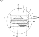
robot arm 100 may have an end-effector (EE) 101, as shown inFig. 3 , and irradiates the laser on the surface of theobject 400 according to the control of the controllingunit 200. Specifically, therobot arm 100 may irradiate with the laser to the surface of theobject 400 in response to a guide path (GP) through the end-effector 101. Such therobot arm 100 may be considered as a manipulator. - The controlling
unit 200 may control the overall function and operation of thelaser irradiation apparatus 10. - The controlling
unit 200 may include avision controlling unit 210 and amotion controlling unit 220. - The
vision controlling unit 210 may receive the raw data having the two-dimensional image and the depth information transmitted from thescanner 300, and configure the three-dimensional image of theobject 400 on the basis of the raw data. - Here, the origin position of the raw data and the direction of the coordinates may vary depending on the
object 400, for example, the shape and volume of the face, or various causes such as the scan starting point of thescanner 300, etc. - In addition, the
vision controlling unit 210 may adjust the coordinates in alignment for the raw data. For this adjustment, thevision controlling unit 210 may detect the position of objects such as eyes, or a nose using face recognition algorithm, and obtain aligning homogeneous matrix. - The
vision controlling unit 210 may set a region of interest (ROI) on the surface of theobject 400 in the three-dimensional image. - The region of interest (ROI) may be a region including a portion that of requiring the laser irradiation, and set the region of interest (ROI) may be set by the user (e.g., physician), or may be automatically set by the three-dimensional image process.
- For example, the user may set the region of interest (ROI) by clicking on the four corner points on the facial surface, and in this case, the normal vector corresponding to each of the corner point may be obtained.
- On the other hand, the
vision controlling unit 210 may determine at least one of the color or the contrast of the surface of theobject 400 based on the data transmitted form thescanner 300, and set the region of interest based on the determined result. - Specifically, the
vision controlling unit 210 may detect a portion where the color or/and the contrast of the surface of theobject 400 is (or are) different form the two-dimensional color image of theobject 400 photographed by thescanner 300. In addition, the vision controlling unit may set the region of the interest to be included the other portion where the color and / or contrast is (or are) different than another portion. - More specifically, the reason for darkly appearing a specific portion is mainly due to the pigment of the depth of the blood vessels, otherwise due to the shaded region by the contour of the skin.
- Therefore, an algorithm may be applied to distinguish the regions which darkly appear due to the pigment or blood vessels of the face or darkly appear in the shade region due to the contour of the skin, and the dermatological treatment method may be changed depending on this distinction.
- For example, if the shaded region, caused by the contour of the skin, is occurred, it is caused by the skin stain or the atrophy of the subcutaneous fat layer due to skin aging, thereby treating firmness treatment, fac implants, fillers, and the like.
- Further, when the shaded region caused by the scar is occurred, it may be necessary the scar treatment.
- In the following, it may be referred to as a region of therapy (ROT) which is necessary for treatment by irradiating the laser on the surface of the object.
- For example, the region of therapy (ROT) may be liver spots, freckles, burn marks, tattoos, acne, dark circles, and the like, those are occurred in the human skin, the present invention is not limited to this, and it may be treatable regions by irradiating the laser of various kinds of wavelength or frequency.
- The
vision controlling unit 210 may determine this portion where color and / or contrast are different surroundings as the region of therapy (ROT). - According to an embodiment of the present invention, the region of interest (ROI) and the region of therapy (ROT) may be set separately as described above, but may be set only the region of therapy (ROT) which is actually irradiated as needed.
- The
vision controlling unit 210 constitutes a motion pattern on the object for the laser treatment on the basis of the determined (or set) information as described above, and the motion pattern may be configured by setting the guide path (GP) passing through the region of interest (ROI) or the region of therapy (ROT). - Then, the
vision controlling unit 210 sets a plurality of points arranged on the guide path (GP). The plurality of points may represent the position where the laser is irradiated on the surface of the object, and the point on the guide path (GP) displayed on the two-dimensional image may be projected on the three-dimensional image. - In addition, the
vision controlling unit 210 obtains the actual laser irradiation points to be irradiated on the surface of the object by selecting only those points positioned within the region of therapy (ROT) of the plurality of points arranged on the guide path (GP). - The
motion controlling unit 220 controls the operation of therobot arm 100 on the basis of the information obtained by thevision controlling unit 210, while the end-effector 101 irradiates the laser as closely moving to the surface of the object. - Here, the interval between the surface of both the end-
effector 101 and the surface of the object during the laser irradiation are preferably and constantly maintained during the movement, the interval may be set based on a focal distance of the laser. - For example, the
motion controlling unit 220 may control the movement and the laser irradiation of therobot arm 100 on the basis of the guide path (GP) and the laser irradiation points set in thevision controlling unit 210. - In addition, the
motion controlling unit 220 may emergently stop the laser irradiation by urgently stopping therobot arm 100, for example, the operation of therobot arm 100 may be stopped by the action or the voice of the doctor or the patient. - The
laser irradiation apparatus 10 according to the present invention may each operate in a manual mode or an automatic mode. - For example, in the automatic mode, the
scanner 300 scans the surface of theobject 400 to obtain the information about the surface of theobject 400, and the controllingunit 200 may irradiate with the laser on the surface of theobject 400 by controlling therobotic arm 100 on basis of the obtained information. - On the other hand, in the manual mode, the user such as a doctor has the controlling authorization, the
robot arm 100 is operated by the control of the user. - It has been described for the configuration of the laser irradiation apparatus with
Figs. 1 to 3 as described above, the present invention shall not be limited, and some of the illustrated elements may be omitted or added additional elements as needed. - For example, the
laser irradiation apparatus 10 further includes a computing unit (not shown) for performing a function of Artificial Intelligence (Al) and a database (not shown) for processing big data. - The laser irradiation method using the
laser irradiation apparatus 10 according to the present invention will be described in detail with reference to the accompanying drawings. -
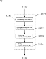
Figs. 4 to 25 are views for explaining the operation of the laser irradiation apparatus according to embodiments of the present invention, the same explanation as explained with reference toFigs. 1-3 of the operation and the construction of thelaser irradiation apparatus 10 will be omitted below. - Referring to
Fig. 4 , the controlling unit determines whether the current setting mode is the automatic mode or not or not (step S100). If the automatic mode is not, the controlling unit determines whether the current setting mode is the manual mode or not (S110). - For example, the user may set by selecting one of the manual mode or the automatic mode using a button mounted in the
laser irradiation apparatus 10 or a user interface (Ul) provided in a touch screen. - It is determined that if the current setting mode is not the manual mode in the step S110, it is performed a different function previously predetermined (for example, Default setting) (S120).
- On the other hand, if the current setting mode is the manual mode, it is determined that the setting status of the manual mode (S130), the controlling authorization is given to the user (S140).
- Here, the operation of giving the controlling authorization to the user means that the controlling
unit 200 may judge for themselves and limit the operation of therobot arm 100. - In the manual mode, the user may operate the
robotic arm 100 on their own while performing the laser treatment. - On the other hand, it is determined that the current setting mode is the automatic mode in the step S100, the
scanner 300 scans the surface of theobject 400 according to the control of the controller 200 (S150). As a result of the scanning by thescanner 300, the raw data including the two-dimensional image and the depth information may be generated. - Here, a screen mode is available to be moved the irradiation position of the laser along the motion of the pointer on a monitor.
- Then, the
vision controlling unit 210 constitutes the three-dimensional image on the basis of the raw data obtained from the scanner 300 (S160). - For example, the canner may scan a plaster cast of a head shape of a person, as shown
Fig. 5(A) , it may be constituted the three-dimensional image as shownFig. 5(B) . - Hereinafter, for convenience of explanation, it will be described where the plaster cast of the head shape is regarded as the
object 400. - After constituting the three-dimensional image, the region of interest (ROI) is set on the surface of the
object 400 in the three-dimensional image (S170). - For example, the first corner point (Pcor, 1), the second corner point (Pcor, two), the third corner point (Pcor, 3), and the four corner point (Pcor, 4) may be set on the surface of the
object 400 in the three-dimensional image, as shown inFig. 5 (C) . Then, the region of interest (ROI) may be set with a region partitioned by the vertices with four corner points such as the first, the second, the third and the four corner points. - In this embodiment, the region of interest (ROI) is set using the four corner points, but the number of corner points to be used the conditions may be changed. For example, it is possible to set the region of interest (ROI) by using at least three corner points.
- Hereinafter, the first corner point (Pcor, 1), the second corner point (Pcor, two), the third corner point (Pcor, 3), and the fourth corner point (Pcor, 4) may be referred as the first point (P1), the second point (P2), the third point (P3), and the fourth point (P4), respectively.
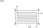
- Then, the guide path (GP) passing through the region of interest (ROI) may be set (step S180).
- For example, as illustrated in
Fig. 6 , it is possible to set the guide path (GP) within the region of interest (ROI). - The starting point of the guide path (GP), i.e. the point at which the laser irradiation is started, is expressed as Ps, while the end point of the guide path (GP), i.e. the point at which the laser irradiation is ended, is expressed as Pt.
- Then, the laser is irradiated in sequence to the laser irradiation points on the surface of the object corresponding to the guide path (GP) (Step S190).
- The guide path (GP) may include a path where the
robot arm 100 is irradiated with the laser. In other words, therobot arm 100 may irradiate with the laser to the surface of the object as moving in response to the guide path (GP). - The guide path (GP) may be regarded as including a path connecting the hitting point of the laser.
- On the other hand, the regions of interest (ROI) may be set based on at least one a color, contrast, contour and texture of the surface of the
object 400. It will be explained with reference toFig. 7 as follows. - Referring to
Fig 7 , in S170 step of setting the region of interest (ROI), the color and / or contrast of the surface of theobject 400 is firstly determined (step S171). Here, the color and / or contrast of the surface of theobject 400 may be determined from the two-dimensional color image of theobject 400. - Since, the determined value is compared with the reference value (S172 step), the region of therapy (ROT), which is different surroundings at least one of contrast and contour, is detected from the surface of the
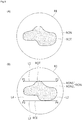
object 400 according to the comparison result (step S173). - For example, a region of normal (RON) and the region of therapy (ROT) may be distinguished on the basis of at least one of a color, contrast, contour and texture on the surface of the
object 400. - As shown in
Fig.8 , when the total 16 of unit areas are arranged in 4 x 4 matrix form, the number expressed on each of the unit area may indicate the brightness value. - Here, it is assumed that the brightness value is 40, it is determined the region of therapy (ROT) with unit areas of (1, 1), (2, 1), (3, 1), (3, 2), (3, 3),(3, 4),(4, 1), (4, 2), (4, 3) and (4, 4) that the brightness value is smaller than 40, and the remained portion may be determined as the region of normal (RON).
- The brightness of the region of therapy (ROT) may appear relatively darker than other portion, that is lower than the brightness of the region of normal (RON). Similarly, the color of the region of therapy (ROT) may appear relatively thicker than the color of the region of normal (RON). The thicker color means more darker than surroundings.
- As such, the brightness value of the region of therapy (ROT) may be a lower portion than a predetermined reference brightness value. The reference brightness value may be varied in various ways depending on the surface state or characteristics (for example, contour or texture, etc.) of the
object 400 or other factors such as the color tone. - Here, the reference brightness value may be a constant, but preferably may be set differently for each patient or treatment region. For example, the reference brightness value may be varied by considering a brightness value of the surrounding region to coincide the skin tone with a region adjacent to the region of therapy (ROT).
- If the face of White is bright as a whole, the reference brightness value may be set relatively high based on the brightness value. The reason is that if the face is appeared with bright white as a whole, a portion requiring the treatment such as dots, spots required, i.e. the region of therapy, is more prominently appeared.
- On the other hand, if the face is Mongoloid appeared relatively dark as a whole than Whites, the reference brightness value may be set relatively low compared with the brightness value of Whites.
- After detecting the region of therapy (ROT), then the regions of interest (ROI) is set (S174).
- As described above, the region of interest (ROI) includes the region of therapy (ROT), the region of interest (ROI) and the region of therapy (ROT) may be equally set.
- As illustrated in
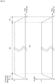
Fig. 9(A) , it is assumed that the region of therapy (ROT), where brightness, color, contour, and texture, etc. are different within the region of normal RON, is included on a predetermined region (R1) of the surface of theobject 400, the form of the region of therapy (ROT) is arbitrarily set for convenience of the description and the present invention is not limited thereto. - In this case, as illustrated in
Fig. 9(B) , it may be set the first, second, third, and fourth points (P1, P2, P3, and P4) to be contacted the first line (L1) connecting the first point (P1) and the second point (P2) with the region of therapy (ROT), the second line (L2) connecting the second point (P2) and the fourth point (P4) with the region of therapy (ROT), the third line (L3) connecting the third point (P3) and the fourth point (P4) with the region of therapy (ROT), and the fourth line (L4) connecting the fourth point (P4) and the first point (P1) with the region of therapy (ROT) . - In addition, regions divided with the first, the second, the third, and the fourth points (P1, P2, P3, and P4) may be set as the region of interest (ROI).
- Here, the region of therapy (ROT) may be also included inside of the region of normal (RON), the region of interest (ROI) may include one portion of the region of normal (RON) as well as the region of therapy (ROT).
- Hereinafter, it is assumed that a portion included within the region of interest (ROI) in the region of normal (RON) is a second region of normal (RON2) and the other portion does not include within the region of interest (ROI) in the region of normal (RON) is a first region of normal (RON1).
- In the case of
Fig. 9 , as setting the region of interest (ROI), it is described only one case that a line connecting two near points is contacted on the region of therapy (ROT), the present invention may not be limited thereto. - For example, as in a case of
Fig.10 , at least one or all lines (L1, L2, L3, and L4) connecting two near points is (or are) not in contact with the region of therapy (ROT). - Thus, the method of setting the region of interest (ROI) may be changed in various ways.
- In case that the shape of the region of therapy (ROT) is the polygonal shape, it may be occurred that the region of therapy (ROT) and the region of interest (ROI) are same depending on the set position of the point.
- On the other hand, the guide path (GP) is capable of being set within the region of therapy (ROT).
- For example, it is possible to set the guide path (GP) with the zigzag form within the region of therapy (ROT), as shown in
Fig11 . - As such, the guide path (GP) is passing through the region of therapy (ROT), the laser is capable of being irradiated in the region of therapy (ROT).
- On the other hand, it is possible to control the fluence and / or frequency of the laser in the beginning step and the end step of the laser irradiation.
- The fluence of the laser represents the laser energy (J / cm2) delivered per unit area, it may means the strength or intensity of the laser. And the laser frequency may means the emission frequency of the laser.
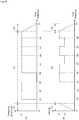
- Referring to
Fig. 12(A) , at least one of the fluence or frequency of the laser is gradually raised in the beginning step of irradiating the laser, while at least one of the fluence or frequency of the laser is gradually decreased in the end step of the irradiating the laser. - In the following description, the beginning step of the laser irradiation is referred to an acceleration section (D1), while the end step of the laser irradiation is referred to a reduction section (D3).
- As shown in
Fig. 12(B) , the moving speed of therobot arm 100 may be increased in the acceleration section (D1). That is, the movement speed of therobot arm 100 may be accelerated. - The occurrence reason of the acceleration section (D1) is because it takes some time from the time of supplying the power operating the
robot arm 100 to the motor to the time of reaching the desired rotation speed. - In addition, in the deceleration section (D3), the moving speed of the
robot arm 100 may be reduced. The reason why the deceleration section D3 is generated is that it takes some time from the time of shutting out the power supply to the motor operating therobot arm 100 to the stop of the motor similarly to the acceleration section D1. - In this way, when the fluence and / or frequency of the laser is gradually risen in acceleration section (D1) and is gradually decreased in the deceleration section (D3), it may be possible to uniformly irradiate the laser.
- The fluence and / or frequency of the laser may be substantially proportional to the moving speed of the
robot arm 100. - At this time, a maintain section (D2) may be occurred between the acceleration section (D1) and the deceleration section (D3), the fluence and / or frequency may substantially and constantly be maintained in the maintain section (D2) if the laser irradiation is not stopped.
- The speed of the
robot arm 100 may be substantially and constantly maintained in the maintain section (D2), for example, the speed of thearm 100 may be constantly maintained during the section (D2) from the time at which the acceleration of therobot arm 100 is ended to the time at which the deceleration is started. - As shown in
Fig. 13(A) , it may be possible that of increasing with step curve the fluence and / or frequency of the laser in the acceleration section (D1) or decreasing in the deceleration section (D3). - In this case, it may be considered to gradually raise the fluence and / or frequency of the laser in the acceleration section (D1), and gradually decrease the fluence and / or frequency of the laser in the deceleration section (D3).
- On the other hand, the guide path (GP) may be possible to deviate outside the region of therapy (ROT) within the region of interest (ROI).
- For example, as shown in
Fig. 14 when the region of interest (ROI) include the region of therapy (ROT) and the region of normal, i.e., the second region of normal (RON2), the guide path (GP) may be passed all regions of the region of therapy (ROT) and the second region of normal (RON2). - In this case, the robot arm for irradiating the laser is turned on in correspondence to the region of therapy (ROT) or turned off in correspondence with the second region of normal (RON2).
- Thus, it is possible to set the guide path (GP) without the relationship of the shape of the region of therapy (ROT) within the region of interest (ROI).
- Further, the guide path (GP) includes a portion passing through the region of therapy (ROT) and the other portions (T1, T2, T3, and T4) passing through the region of normal (RON2) deviating outside the region of therapy (ROT).
- As shown in
Fig. 15 , therobot arm 100 may turn off the laser irradiation corresponding to the portion passing through the second region of normal (RON2) in the guide path (GP). In other words, it is considered that therobot arm 100 may turn on/off the laser irradiation depending on at least one color, brightness, and contour of the surface of theobject 400 in the course of irradiating the laser along the guide path (GP). - That is, the
robot arm 100 moves corresponding to the guide path (GP) and may turn on the laser irradiation corresponding to the portion, where the color is appeared more darker or the brightness is lower than the surroundings, that is the region of therapy (ROT) and turn off the laser irradiation corresponding to the portion, where the color is appeared more lighter or the brightness is higher than the surroundings, that is the region of normal (RON). - Referring to
Fig. 15 , it may be known that the laser frequency and / or fluence is set substantially zero in the portions (T1, T2, T3, and T4) where therobot arm 100 is passing through the second region of normal (RON2). - In this case, the movement of the robot arm is possible to maintain substantially and constantly, thereby improving the accuracy of the treatment.
- On the other hand, it is possible to adjust at least one of the frequency, the irradiation time, the number of the laser irradiation, the fluence of the laser depending on the degree of color and / or brightness of the region of therapy (ROT) under the control of the
motion controlling unit 220. - Referring to
Fig. 16 , the region of therapy (ROT) may include the first region of therapy (ROT1) and the second region of therapy (ROT2). - Here, the color of the second region of therapy (ROT2) may be darker than the first region of therapy (ROT1), or the brightness of the second region of therapy (ROT2) may be lower than the brightness of the first region of therapy (ROT1).
- Alternatively, the brightness of the second region of therapy (ROT2) may be lower than the critical brightness value predetermined in advance, while the brightness of the first region of therapy (ROT1) may be higher than the critical brightness value predetermined in advance.
- In this case, the second region of therapy (ROT2) may be considered as a portion required intensive care compared to the first region of therapy (ROT1).
- In this embodiment of the present invention, it is referred to as the first point X1 for a boundary point between the second region of normal (RON2) and the first region of therapy (ROT1) on the guide path (GP) as sequentially moving at the starting point Ps of the laser, the second point X2 for a boundary point between the first region of therapy (ROT1) and the second region of therapy (ROT2), the third point X3 for a boundary point between the second region of therapy (RON2) and the second region of normal (ROT2), the fourth point X4 for a boundary point between the second region of normal (RON2) and the first region of therapy (ROT1), the fifth point X5 for a boundary point between the first region of therapy (ROT1) and the second region of therapy (ROT2), the sixth point X6 for a boundary point between the second region of therapy (ROT2) and the first region of therapy (ROT1), the seventh point X7 for a boundary point between the first region of therapy (ROT1) and the second region of therapy (ROT2), and the eighth point X8 for a boundary point between the second region of therapy (ROT2) and the first region of therapy (ROT1).
- As shown in
Fig. 17 , the robot arm may turn off the laser irradiation in sections from the start point (Ps) of the laser to the first point (X1) and from the third point (X3) to the fourth point (X4), respectively. - For example, since Ps- X1 section and X3-X4 section are included in the second region of normal (RON2), thus the
robot arm 100 may not irradiate the laser. - On the other hand, the frequency of the laser is set at the first frequency (f1) in X1-X2 section, X4-X5 section, X6-X7 section and the section from the eighth point (X8) to the beginning of the deceleration section (D3).
- And, it may be gradually varied the gradation of the irradiation conditions through the variations of the laser irradiation frequency or the laser irradiation fluence by the variation in velocity of the end-
effector 101, or the adjustment of the laser fluence or pulse duration in X1, X3 and X4 points. - Further, in the other points except X1, X3 and X4 points, the gradation of the irradiation conditions as described above may be gradually achieved.
- On the other hand, in X2-X3, X5-X6, and X7-X8 sections, the frequency of the laser may set with a second frequency (f2) that is higher than the first frequency (f1).
- In this case, the laser, which is relatively stronger, may be irradiated on the second region of therapy (ROT2) thereby improving the treatment efficiency.
- Referring to
Fig. 18(A) , the frequency of the laser may equally set as the first frequency (f1) in X1-X3 section, X4-X8 section and a section from the eighth point (X8) to the beginning of the deceleration section (D3). - Thus, while maintaining the frequency of the laser, as shown in
Fig.18(B) , the movement speed of therobot arm 100 may set at the first speed (V1) in a section from a point of the end of the acceleration section D1 to the second point X2, X3-X5 section, X6-X7 section, and the section from the eighth point (X8) to the beginning of the deceleration section (D3). - On the other hand, the movement speed of the
robot arm 100 may be set at the second speed (V2) which is slower than the first speed (V1) in X2-X3, X5-X6, and X7-X8 sections. - In this case, the laser may irradiate relatively longer than the second region of therapy (ROT2) thereby improving the treatment efficiency.
- That is, in the case that the speed of the end-effecter (EE) and the fluence of the laser are constant and the emission frequency of the laser is higher, the overlapping rate of the laser is relatively higher in the second region of therapy (ROT2), thereby providing more amount of the laser energy.
- On the other hand, for the second region of therapy (ROT2), the number of treatments may be set a lot more than the first region of therapy (ROT1). For this, it will be described below referring to
Fig. 19 . -
Fig. 19(A) shows the status that therobot arm 100 may irradiate the laser for the first laser treatment on the surface of theobject 400 along the guide path (GP) within the region of interest (ROI), whileFig. 19(B) shows the status that of performing the second laser irradiation carried out after the end of the first laser treatment. - Referring to
Fig. 19(A) , therobot arm 100 may irradiate the laser in X1-X3 section, X4-X8 section and a section from the eighth point (X8) to before the deceleration section (D3), in which the frequency of the laser may be equally set at the first frequency (f1). - Referring to
Fig. 19(B) , in the second course of the laser treatment, therobotic arm 100 may irradiate the laser in X2-X3 section, X5-X6 section, and X7-X8 section corresponding to the second region of therapy (ROT2), in which it may be equally set to the frequency of the laser corresponding to the difference between the second frequency (f2) and the first frequency (f1). - Thus, the therapeutic effect similar to that of irradiating the laser of the second frequency (f2) may be occurred in the second region of therapy (ROT2).
- According to the present invention, as in the case of
Fig. 20 , the end-effector 101 of therobot arm 100 preferably irradiates the laser approximately perpendicular to the surface of theobject 400 to increase the therapeutic efficacy and to improve the treatment accuracy. - To this end, the
robot arm 100 may be desirable with degree of freedom (DOF). Specifically, therobot arm 100 may be desirable to have five degrees of freedom, and it is preferably have at least six degrees of freedom for exceptional circumstances. - The laser irradiation experiment conducted by using the
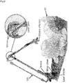
laser irradiation apparatus 10 according to the present invention is described inFigs. 21 and22 . - Referring to
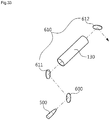
Fig. 21 , it is disclosed an example that therobot arm 100, including a laser emitter, a motor, a motor drive, a reflecting mirror and an end- effector (EE), irradiates the laser onto the surface of theobject 400 that is the plaster cast of head shape. - The motors and the motor drive may operate the
robot arm 100. - When the laser emitter is emitted the laser, the reflecting mirror may reflect at a predetermined angle thereby reaching the laser to the end-effector.
- Then, the end-effector may irradiate the laser on the surface of the
object 400. - Referring to
Fig. 22 , it may be confirmed that the guide path (GP) is set in the spiral on the surface of theobject 400.Fig. 22 shows that it is photographed the laser irradiation on the surface of theobject 400 in a constant duration and implemented by the shape of the guide path (GP). - On the other hand, it is possible to stop the laser irradiation depending on the conditions or to modify the guide path. The detailed explanation will be described as follows.
- Referring to
Fig.23 , the motion of theobject 400 may be determined after setting the guide path (GP) or irradiating the laser (S200). For example, if theobject 400 is a person's head, it may be determined whether there is a motion in a corresponding section or not by looking at a specific portion such as a nose, both eyes. Or, if the surface of theobject 400 is moved, for example, the skin of a person is moved cause by the reasons such as convulsions in the skin of a person's face, it may be considered that the movement of theobject 400 is exist. - As determined result, if there is no motion of the
object 400, it may be maintained a predetermined guide path (GP) (S210). - On the other hand, if it is determined that the motion of the
object 400 may be measured, it may measure the amount of motion of the object (400) (S220). The measurement of the amount of motion of theobject 400 means to be determined that how long theobject 400 is moved. - It is determined that whether the motion amount exceeds a threshold range previously set or not as the result of measuring the motion amount (S230).
- It determined that, if the motion amount of the
object 400 is greater than the threshold range previously set, it is possible to perform the emergency stop mode(S240). In this case, it is possible to urgently stop the laser irradiation. - On the other hand, if the motion amount of the
object 400 does not exceed the threshold range, the region of interest (ROI) may be reset in consideration of the motion amount (S250). - In this embodiment, it is considered that the
motion controlling unit 220 compensates or corrects the guide path, when thescanner 300 collects the motion of theobject 400 and thevision controlling unit 210 newly reset the region of interest (ROI). - In addition, the guide path (GP) may also be modified corresponding to the reset of the region of interest (ROI) (S260).
- For example, as in the case of
Fig. 24 , if theobject 400 is moved toward left upper side 1cm, then the region of interest (ROI) is also moved toward the left upper side 1cm. Correspondingly, the guide path (GP) may also be moved toward the upper left 1cm. - Then, the laser may be irradiated on the surface of the
object 400 corresponding to the modified guide path (GP) (S270). - As such, if the motion of the
object 400 is occurred in the laser treatment process, it may be possible to modify the guide path (GP) in real time according to the motion of theobject 400. - On the other hand, in the above description, it is described the embodiment as below that the
object 400 is moved up, down, left or right on the same plane, it may be also be adapted when moving back and forth by maintaining the interval between the end-effecter (EE) of the laser irradiation apparatus and the surface of theobject 400. - In case that the vibration is generated and the force is applied in the
laser irradiation apparatus 10, it is possible to perform the emergency stop mode. - For example, as shown in
Fig. 25 , it may be determined that whether the vibration is generated or the force is applied or not after setting the guide path (GP) or irradiating the laser (S300). - As determined result, if the vibration is not generated or the force is not applied, it may be maintained the predetermined guide path (GP) (S310).
- On the other hand, it is determined that the vibration is generated, or the force is applied, it may measure the vibration and / or the force (S320).
- As the measured result, it may be determined that whether the vibration is generated more than a reference value previously set, or applied the force more than a threshold value previously set(S330).
- As the measured result, if the vibration is generated more than the reference value, or applied the force more than the threshold value, it may perform the emergency stop mode (S340). In this case, it is possible to urgently stop the laser irradiation.
- On the other hand, if the vibration is generated less than the reference value, or applied the force lower more than the threshold value, it may reset the region of interest (ROI) in consideration of the vibration and / or the force (S350).
- In addition, the guide path (GP) may also be modified corresponding to the reset of the region of interest (ROI) (S360).
- Then, the laser may be irradiated on the surface of the
object 400 corresponding to the modified guide path (GP) (S370). - For example, the
laser irradiation apparatus 10 may be urgently stopped to cease the laser irradiation where the vibration equal to or larger than the reference value is generated in therobot arm 100 when someone touches the laser irradiation apparatus or touches a table on which the patient is lying, or an earthquake occurrence in the course of the treatment procedure. Alternatively, thelaser irradiation apparatus 10 may be urgently stopped to stop the laser irradiation, during the treatment procedure, the user (doctor or the like) finds a procedure error and holds therobot arm 100 by hand thereby applying the force equal to or greater than a threshold value to therobot arm 100. - For the robot arm to be applied to the laser irradiation apparatus, it will be described above referring to the accompanying drawings as follows.
-
Figs. 26 to 34 are views for explaining the embodiment of the structure of the robot arm, it may be omitted the explanation as described above in the following description. The explanation described as above may be implemented using therobot arm 100. - The
first link 130, thesecond link 140, thefirst end part 161, thesecond end part 162 and thethird end part 163 may be used as a hollow type pope, respectively. Accordingly, the laser emitted from alaser unit 500 may be transferred to the end-effector 101 through thefirst link 130, thesecond link 140, thefirst end part 161, and thesecond end part 162, and thethird end part 163 as reflecting to the predetermined mirror. More detailed explanation will be described as below. - Referring to
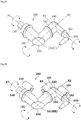
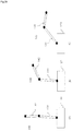
Figs. 26 - 30 , therobot arm 100 may include thefirst base part 110, thesecond base part 120, thefirst link 130, thesecond link 140, anauxiliary link 150, alaser unit 500, thefirst motor part 170, thesecond motor part 180 and thethird motor part 190. - The
laser unit 500 is disposed on thefirst base part 110 to generate the laser. - The
second base part 120 may be coupled to be rotatable onto thefirst base part 110. - The
second base part 120, as shown inFig. 28 may confirm that of swinging onto thefirst base part 110. - The
first motor part 170 is disposed on thefirst base part 110 to rotate thesecond base part 120. - Referring to
Figs. 26 ,27 and29 , thefirst link 130 may be coupled to enable swing onto thesecond base part 120. - The
second motor part 180 is disposed on thesecond base part 180 to swing thefirst link 130. -
Fig. 29 shows an example of a case that thefirst link 130 is swinging about the connecting portion with thesecond base part 120. - The
first mirror part 600 may be disposed in thesecond base part 120. Thefirst mirror part 600 is capable of reflecting the laser emitting from to thelaser unit 500 towards thefirst link 130 corresponding to thelaser unit 500. - The
second mirror part 610 corresponding to thefirst mirror part 600 may be disposed in thefirst link 130. Thesecond mirror part 610 may include thefirst sub-mirror 611 and the second sub-mirror 612 as disclosed inFigs. 29 and30 . - The first sub-mirror 611 may correspond to the
first mirror part 600, while the second sub-mirror 612 may correspond to thefirst sub-mirror 611. - The
second mirror part 610 may reflect the laser, reflected by thefirst mirror part 600, toward thesecond link 140. Specifically, thefirst sub-mirror 611 of thefirst mirror part 610 reflects the laser reflected by thefirst mirror part 600 toward thesecond sub-mirror 612, the second sub-mirror 612 may reflect the laser reflected by the first mirror part toward thethird mirror part 620 disposed in thesecond link 140. Thethird mirror part 620 may reflect the laser reflected by the second sub-mirror 612 toward anend part 160. - Referring to
Figs. 26 ,27 and30 , thesecond link 140 may be coupled to enable to swing onto thefirst link 130. - One end of the
auxiliary link 150 is coupled to thesecond base part 120, the other end may be coupled to thesecond link 140. To this end, it is arranged the first extendingarm 141 extending in the extension direction that is the opposite direction of thesecond link 140 in the end of thesecond link 120. In addition, thesecond reduction gear 520 is arranged in thesecond base part 120, and a second extendingarm 151 may be arranged in thesecond reduction gear 520. - One end of the
auxiliary link 150 is coupled to thesecond base part 120 by connecting to the second extendingarm 151, while the other end of theauxiliary link 150 is coupled to thesecond link 140 by connecting to the first extendingarm 141. - The
third motor part 190 is arranged on thesecond base part 120, and may swing thesecond link 140 through thesecondary link 150. Specifically, thethird motor part 190 may swing thesecondary link 150 up and down directions, thereby swing thesecond link 140 may swing by the up and down movement of theauxiliary link 150. For example, thethird motor part 190 is rotated, the second extendingarm 151 is moving, also theauxiliary link 150 is moving up and down directions, thus, thesecond link 140 may swing as shown inFig. 30 . - The
second reduction gear 520 is coupled to thethird motor part 190, the number of rotations of thethird motor part 190 may be reduced to the required number of rotations. In some cases, thesecond reduction gear 520 may be omitted. - As shown in
Figs. 26 and27 , thefirst reduction gear 510 may be arranged in thesecond base part 120. - The
first speed reducer 510 is connect to thesecond motor part 180, the number of rotations of thesecond motor part 180 may be reduced to the required the number of rotations. In some cases, thefirst reduction gear 510 may be omitted. - The
end part 160 may be coupled to thesecond link 140. - Referring to
Figs. 31 and 32 , theend part 160 has thefirst end part 161, thesecond end part 162 and thethird end part 163. - In addition, the
end part 160 may include the end-effector (EE) 101 for irradiating the laser to the object, for example, the skin of the patient. The end-effector 101 may be arranged on thethird end part 163. - The
first end part 161 is couple to thesecond link 140 and may rotate onto the first axis X1. - The
second end part 162 may couple to theend part 161, and may be rotated onto the second axis X2 perpendicular to the first axis X1. - The
third end part 163 is coupled to thesecond end part 162 and rotatable onto the third axis X3 perpendicular to the second axis X2. - The first, second, and
third end parts - The
fourth mirror part 630 corresponding to thethird mirror part 620 may be arranged in thefirst end part 161. For example, thefourth mirror part 630 may be arranged in the bent portion of thefirst end part 161. - In addition, the
fifth mirror part 640 corresponding to thefourth mirror part 630 may be arranged in thesecond end part 162. For example, thefifth mirror part 640 may be arranged in the bent portion of thesecond end part 162. - The
sixth mirror part 650 corresponding to thefifth mirror part 640 may be arranged in thethird end part 163. For example, thesixth mirror part 650 may be arranged in the bent portion of thethird end part 163. - The
first end part 161 is rotatable onto the first axis X1 by thefourth motor part 164. Thefourth motor part 164 may be arranged on thefirst end part 161. - The
second end part 162 may be rotated onto the second axis X2 by thefifth motor part 165. Thefifth motor part 165 may be arranged in thesecond end part 162. - The
third end part 163 may be rotated onto the third axis X3 by thesixth motor part 166. Thesixth motor part 166 may be arranged on thethird end part 163. - If the
laser unit 500 irradiates the laser, as shown inFig. 33 , the laser may be directed to thethird mirror 620 by reflecting thefirst mirror part 600, and thefirst sub-mirror 611 and the secondsub-mirror mirror 612 of thesecond mirror part 610. - Then, the laser reflected by the second sub-mirror 612 may be reached to the end-
effector 101 through thethird mirror part 620, thefourth mirror part 630, thefifth mirror part 640 and thesixth mirror part 650. The laser reached in the end-effector 101 may irradiate the laser to the outside. - On the other hand, the movement of the
third end part 163 may be limited compared to the movement of thefirst end part 161 and / or thesecond end part 162. - For example, if the portion for irradiating the laser is determined, it maximumly approaches the end-
effector 101 to corresponding place by primarily moving thefirst link 130 and / or thesecond link 140. And it may be closer to the end-effector 101 in its place by moving thefirst end part 161 and / or thesecond end part 162. If it is difficult to approach the end-effector to a desired place with the movement of thefirst link 130, thesecond link 140, thefirst end part 161 and / or thesecond end part 162, then it may operate the end-effector by moving thethird end part 163. - Or, third, it is possible to set to be minimized the maximum operational range of the
end part 163 than the operational range of thefirst end part 161 and / or thesecond end part 162. - On the other hand, if the second mirror part may be configured with the
first sub-mirror 611 and thesecond sub-mirror 612, the operational radius of therobot arm 100 may be widen, thereby improving the efficiency of the laser treatment. - Specifically, as shown in
Fig.30 , when thefirst sub-mirror 611 is arranged on an end of thefirst link 130, and second sub-mirror 612 is also arranged on the other end of thefirst link 130, the laser irradiated from thelaser unit 500 may be effectively reflected toward thesecond link 140 and may be set more freely the swinging direction of thesecond link 140. For example, it is possible to equally make of the swing directions of thefirst link 130 and thesecond link 140. - In this case, as shown in
Fig. 34(A), 34(B), and 34(C) , the operational radius of therobot arm 100 may be widened, since thefirst link 130 and thesecond link 140 may move in the same direction, - Although the configuration of the
robot arm 100 according to the embodiment of the present invention has been described above with reference toFigs. 26 to 34 , the present invention is not limited to the illustrated configuration, some of the illustrated components may be omitted or additional components may be added as needed. - For example, the
first link 130 coupled to be swing on thesecond base unit 120 may be omitted, if necessary. - Although the embodiment of the present invention has been described with reference to the laser irradiation apparatus using the robot arm, but the present invention is not limited thereto. In addition, it may be applicable to control movement patterns in various types of a gantry type laser irradiation apparatus for wrapping a patient's face or the laser irradiating apparatus in the shape of the laser array patch attached to a patient's face.
- Further, although the present invention is described as the example with reference to the laser irradiation apparatus using the robot arm, the technical construction of the present invention may be applicable to a variety of energy based medical device, for treating the skin, using the high frequency, ultrasound, IPL (Intense Pulse Light), Psoralen-UV-A (PUVA), etc.
- On the other hand, the embodiment of the present invention is described in referring to an example that the
robotic arm 100 of the laser irradiation apparatus delivers the laser to the end-effector (EE) from the laser emitter using the plurality of reflecting mirrors, but the present invention is not limited to thereto, but the laser may be delivered to the end- effector (EE) by the optical fiber. - The laser irradiation method using the robot arm according to the present invention may be stored in a computer-readable recording medium manufactured as a program to be executed in a computer, examples of the computer-readable recording medium include ROM, RAM, CD-ROM, a magnetic tape, a floppy disc, optical data storage devices, and it is implemented in the form of carrier waves (such as data transmission through the Internet).
- Further, the computer-readable recording medium is distributed over network coupled computer systems so that the computer readable code is stored and executed in a distributed fashion. Then, the functional (functional) programs, codes, and code segments for accomplishing the present invention can be easily construed by programmers skilled in the art to which the invention pertains.
Claims (6)
- A laser irradiation apparatus (10) using a robot, comprising:a scanner (300) for scanning an object (400) to collect a raw data;a vision controlling unit (210) for constituting a three-dimensional image of the object (400) on the basis of the raw data, and setting a region of interest (ROI) on the surface of the object (400) in the three-dimensional image;a motion controlling unit (220) for setting a guide path (GP) passing through the region of interest (ROI); anda robot arm (100), having an end-effector (101), for irradiating a laser on the surface of the object (400) corresponding to the guide path (GP),wherein the robot arm (100) comprises:a first base part (110);a second base part (120) being coupled to be rotatable on the first base part (110);a first link (130) being coupled so that it can swing on the second base part (120);a second link (140) being coupled so that it can swing on the first link (130);an auxiliary link (150) having one end coupled to the second base part (120) and the other end coupled to the second link (140);a laser unit (500), arranged on the first base part (110), for generating the laser;a first motor part (170), arranged on the first base part (110), for rotating the second base part (120);a second motor part (180), arranged on the second base part (120), for swinging the first link (130); anda third motor part (190), arranged on the second base part (120), for swinging the second link (140) through the auxiliary link (150).
- The laser irradiation apparatus (10) according to claim 1, wherein the scanner (300) comprises:a color sensor (310) for photographing a two-dimensional color image; andan IR projector (320) and an IR sensor (330) for obtaining depth data.
- The laser irradiation apparatus (10) according to claim 1, wherein the vision controlling unit (210) is configured to detect a region of therapy (ROT) where at least one of a color or a contrast is different from surroundings on the surface of the object (400), and set the region of interest (ROI) to include the region of therapy (ROT).
- The laser irradiation apparatus (10) according to claim 3, wherein the guide path (GP) is passing through the region of therapy (ROT), and the robot arm (100) is configured to irradiate the laser on the treatment area.
- The laser irradiation apparatus (10) according to claim 3, wherein the motion controlling unit (220) is configured to adjust at least one of a frequency, an irradiation time, a number of irradiation times, and a fluence of the laser according to at least one of a degree of a color or a brightness of the region of therapy (ROT).
- The laser irradiation apparatus (10) according to claim 1, wherein the motion controlling unit (220) is configured to modify the guide path (GP) along a motion of the object (400), when the motion of the object (400) is generated during the treatment process.
Applications Claiming Priority (3)
| Application Number | Priority Date | Filing Date | Title |
|---|---|---|---|
| KR1020160047354A KR102594428B1 (en) | 2016-04-19 | 2016-04-19 | Apparatus For Laser Emitting using Robot-Arm |
| KR1020160047353A KR102594427B1 (en) | 2016-04-19 | 2016-04-19 | Apparatus and Method For Laser Emitting using Robot-Arm |
| PCT/KR2017/003440 WO2017183825A1 (en) | 2016-04-19 | 2017-03-29 | Laser irradiation apparatus and method using robot arm |
Publications (3)
| Publication Number | Publication Date |
|---|---|
| EP3446750A1 EP3446750A1 (en) | 2019-02-27 |
| EP3446750A4 EP3446750A4 (en) | 2019-05-01 |
| EP3446750B1 true EP3446750B1 (en) | 2021-03-24 |
Family
ID=60116962
Family Applications (1)
| Application Number | Title | Priority Date | Filing Date |
|---|---|---|---|
| EP17786094.7A Active EP3446750B1 (en) | 2016-04-19 | 2017-03-29 | Laser irradiation apparatus using robot arm |
Country Status (5)
| Country | Link |
|---|---|
| US (1) | US11103310B2 (en) |
| EP (1) | EP3446750B1 (en) |
| JP (1) | JP2019513501A (en) |
| CN (1) | CN109069855A (en) |
| WO (1) | WO2017183825A1 (en) |
Families Citing this family (12)
| Publication number | Priority date | Publication date | Assignee | Title |
|---|---|---|---|---|
| CA3112985A1 (en) * | 2018-10-11 | 2020-04-16 | Lumenis Ltd | Real time monitoring of cosmetic laser aesthetic skin treatment procedures |
| CN109581651B (en) * | 2018-12-10 | 2020-10-20 | 北京航空航天大学 | Laser scanning device for medical robot |
| US20210186610A1 (en) * | 2019-12-23 | 2021-06-24 | Blossom Innovations | Systems, methods and computer-accessible medium for providing feedback and analysis on an electromagnetic-based treatment device |
| CN112587802B (en) * | 2020-12-07 | 2021-12-07 | 盐城东紫光电科技有限公司 | Pulse phototherapy equipment with adsorption function |
| CN113065553A (en) * | 2021-04-01 | 2021-07-02 | 杭州思看科技有限公司 | Data processing method and device, three-dimensional scanning system and electronic device |
| WO2022224123A1 (en) * | 2021-04-19 | 2022-10-27 | Slovenská Technická Univerzita V Bratislave | Robotic epilation workplace and method of epilation performed at this workplace |
| CN113290562A (en) * | 2021-05-28 | 2021-08-24 | 上海禾苗创先智能科技有限公司 | Control method and device of laser physical therapy robot, computer equipment and storage medium |
| CN113487510A (en) * | 2021-07-16 | 2021-10-08 | 中国科学院自动化研究所 | Method, system and equipment for detecting needle point position for automatic liquid preparation of robot |
| US11819708B1 (en) | 2022-05-17 | 2023-11-21 | BellaMia Technologies, Inc. | Robotic laser treatment safety system |
| WO2023225411A1 (en) * | 2022-05-17 | 2023-11-23 | BellaMia Technologies, Inc. | Systems and methods for laser skin treatment |
| US11931102B2 (en) | 2022-05-17 | 2024-03-19 | BellaMia Technologies, Inc. | Laser treatment safety system |
| CN116473681B (en) * | 2023-03-28 | 2024-02-20 | 北京维卓致远医疗科技发展有限责任公司 | Control system and method of surgical robot |
Family Cites Families (22)
| Publication number | Priority date | Publication date | Assignee | Title |
|---|---|---|---|---|
| US4697590A (en) * | 1984-12-24 | 1987-10-06 | Shibuya Kogyo Co., Ltd. | Apparatus for treating athlete's foot |
| US20030060810A1 (en) * | 2000-02-16 | 2003-03-27 | Diego Syrowicz | Method and apparatus for treating and/or removing an undesired presence on the skin of an individual |
| US7083611B2 (en) | 2003-12-19 | 2006-08-01 | Marc S. Lemchen | Method and apparatus for providing facial rejuvenation treatments |
| JP4995826B2 (en) * | 2005-09-30 | 2012-08-08 | レストレーション ロボティクス,インク. | Automatic system for collection and transplantation of hair follicle units |
| US7962192B2 (en) * | 2005-09-30 | 2011-06-14 | Restoration Robotics, Inc. | Systems and methods for aligning a tool with a desired location or object |
| CN101400313B (en) * | 2006-02-01 | 2011-06-08 | 通用医疗公司 | Apparatus for controlling at least one of at least two sections of at least one fiber |
| CN101505675A (en) * | 2006-06-27 | 2009-08-12 | 帕洛玛医疗技术公司 | Handheld photocosmetic device |
| US9084622B2 (en) * | 2006-08-02 | 2015-07-21 | Omnitek Partners Llc | Automated laser-treatment system with real-time integrated 3D vision system for laser debridement and the like |
| US7822249B2 (en) * | 2006-08-25 | 2010-10-26 | The Trustees Of Columbia University In The City Of New York | Systems and methods for high-throughput radiation biodosimetry |
| US8036448B2 (en) * | 2007-04-05 | 2011-10-11 | Restoration Robotics, Inc. | Methods and devices for tattoo application and removal |
| KR100862274B1 (en) * | 2007-04-24 | 2008-10-09 | (주)아모레퍼시픽 | Method for valuating the human skin disruption by quantitative analyzing and visual expressing the furrows |
| DE102008056136A1 (en) * | 2008-10-29 | 2010-05-20 | 3D-Micromac Ag | Laser marking method, laser marking device and optical element |
| CN100594009C (en) * | 2008-12-26 | 2010-03-17 | 天津医科大学 | Self-controlled laser surgery equipment |
| CN101670152B (en) * | 2009-09-10 | 2012-05-23 | 北京理工大学 | Photodynamic therapy system |
| KR101015881B1 (en) * | 2010-06-17 | 2011-02-23 | 이용수 | The treatment system of scars and cutaneous disorder, and the method thereof |
| US20120071794A1 (en) * | 2010-09-20 | 2012-03-22 | Alma Lasers Ltd. | Robotic System for Delivering Energy for Treatment of Skin of a Subject |
| SG11201507679RA (en) * | 2013-03-15 | 2015-10-29 | Univ Carnegie Mellon | A supervised autonomous robotic system for complex surface inspection and processing |
| US9167999B2 (en) * | 2013-03-15 | 2015-10-27 | Restoration Robotics, Inc. | Systems and methods for planning hair transplantation |
| US9675419B2 (en) | 2013-08-21 | 2017-06-13 | Brachium, Inc. | System and method for automating medical procedures |
| CN107205794A (en) * | 2013-10-09 | 2017-09-26 | 北京大学口腔医学院 | Digital control laser automates tooth preparation method and equipment and tooth positioner |
| CN104288914B (en) * | 2014-08-25 | 2017-02-08 | 吉林大学中日联谊医院 | Intelligent laser therapy apparatus for treating onychomycosis |
| CN105169570A (en) | 2015-09-24 | 2015-12-23 | 北京大学 | Imaging guided intelligentialized laser minimally invasive surgery system and control method thereof |
-
2017
- 2017-03-29 WO PCT/KR2017/003440 patent/WO2017183825A1/en active Application Filing
- 2017-03-29 JP JP2018555459A patent/JP2019513501A/en active Pending
- 2017-03-29 EP EP17786094.7A patent/EP3446750B1/en active Active
- 2017-03-29 US US16/094,821 patent/US11103310B2/en active Active
- 2017-03-29 CN CN201780024732.6A patent/CN109069855A/en active Pending
Non-Patent Citations (1)
| Title |
|---|
| None * |
Also Published As
| Publication number | Publication date |
|---|---|
| CN109069855A (en) | 2018-12-21 |
| US11103310B2 (en) | 2021-08-31 |
| JP2019513501A (en) | 2019-05-30 |
| EP3446750A1 (en) | 2019-02-27 |
| US20190117307A1 (en) | 2019-04-25 |
| EP3446750A4 (en) | 2019-05-01 |
| WO2017183825A1 (en) | 2017-10-26 |
Similar Documents
| Publication | Publication Date | Title |
|---|---|---|
| EP3446750B1 (en) | Laser irradiation apparatus using robot arm | |
| US11033331B2 (en) | Method for controlling moving pattern for laser treatment and laser irradiation device using same | |
| US11065469B2 (en) | Region division method for laser treatment, and laser treatment method and apparatus using the same | |
| EP3446752B1 (en) | Laser irradiation apparatus | |
| US20030060810A1 (en) | Method and apparatus for treating and/or removing an undesired presence on the skin of an individual | |
| US20160106516A1 (en) | Systems for automated biomechanical computerized surgery | |
| US20120071794A1 (en) | Robotic System for Delivering Energy for Treatment of Skin of a Subject | |
| KR101707654B1 (en) | Laser Procedure System | |
| US20100049098A1 (en) | Automatic acoustic treatment device | |
| KR102594427B1 (en) | Apparatus and Method For Laser Emitting using Robot-Arm | |
| CA3230232A1 (en) | Image guided laser therapy | |
| TWI450742B (en) | Optical apparatus | |
| KR20170119402A (en) | Apparatus and Method For Laser Emitting using Robot-Arm | |
| KR102594428B1 (en) | Apparatus For Laser Emitting using Robot-Arm | |
| KR20180102031A (en) | Area grouping method for laser therapy, laser therapy method and apparatus thereof | |
| KR20180064087A (en) | Method of movement pattern control for laser therapy and laser emitting device | |
| KR20230053062A (en) | Laser irradiation apparatus using object recognition and control method thereof | |
| JP2023527915A (en) | Low level laser targeting system for photobiomodulation therapy | |
| KR20240058464A (en) | Body-costomized light irradiation apparatus and control method thereof |
Legal Events
| Date | Code | Title | Description |
|---|---|---|---|
| STAA | Information on the status of an ep patent application or granted ep patent |
Free format text: STATUS: THE INTERNATIONAL PUBLICATION HAS BEEN MADE |
|
| PUAI | Public reference made under article 153(3) epc to a published international application that has entered the european phase |
Free format text: ORIGINAL CODE: 0009012 |
|
| STAA | Information on the status of an ep patent application or granted ep patent |
Free format text: STATUS: REQUEST FOR EXAMINATION WAS MADE |
|
| 17P | Request for examination filed |
Effective date: 20181018 |
|
| AK | Designated contracting states |
Kind code of ref document: A1 Designated state(s): AL AT BE BG CH CY CZ DE DK EE ES FI FR GB GR HR HU IE IS IT LI LT LU LV MC MK MT NL NO PL PT RO RS SE SI SK SM TR |
|
| AX | Request for extension of the european patent |
Extension state: BA ME |
|
| A4 | Supplementary search report drawn up and despatched |
Effective date: 20190329 |
|
| RIC1 | Information provided on ipc code assigned before grant |
Ipc: A61B 18/20 20060101ALI20190325BHEP Ipc: A61N 5/067 20060101ALI20190325BHEP Ipc: A61N 5/06 20060101AFI20190325BHEP Ipc: A61B 34/30 20160101ALI20190325BHEP Ipc: A61B 5/00 20060101ALI20190325BHEP Ipc: A61B 18/00 20060101ALI20190325BHEP |
|
| DAV | Request for validation of the european patent (deleted) | ||
| DAX | Request for extension of the european patent (deleted) | ||
| STAA | Information on the status of an ep patent application or granted ep patent |
Free format text: STATUS: EXAMINATION IS IN PROGRESS |
|
| 17Q | First examination report despatched |
Effective date: 20200207 |
|
| GRAP | Despatch of communication of intention to grant a patent |
Free format text: ORIGINAL CODE: EPIDOSNIGR1 |
|
| STAA | Information on the status of an ep patent application or granted ep patent |
Free format text: STATUS: GRANT OF PATENT IS INTENDED |
|
| INTG | Intention to grant announced |
Effective date: 20201002 |
|
| GRAS | Grant fee paid |
Free format text: ORIGINAL CODE: EPIDOSNIGR3 |
|
| GRAA | (expected) grant |
Free format text: ORIGINAL CODE: 0009210 |
|
| STAA | Information on the status of an ep patent application or granted ep patent |
Free format text: STATUS: THE PATENT HAS BEEN GRANTED |
|
| AK | Designated contracting states |
Kind code of ref document: B1 Designated state(s): AL AT BE BG CH CY CZ DE DK EE ES FI FR GB GR HR HU IE IS IT LI LT LU LV MC MK MT NL NO PL PT RO RS SE SI SK SM TR |
|
| REG | Reference to a national code |
Ref country code: GB Ref legal event code: FG4D |
|
| REG | Reference to a national code |
Ref country code: CH Ref legal event code: EP |
|
| REG | Reference to a national code |
Ref country code: IE Ref legal event code: FG4D |
|
| REG | Reference to a national code |
Ref country code: AT Ref legal event code: REF Ref document number: 1373879 Country of ref document: AT Kind code of ref document: T Effective date: 20210415 Ref country code: DE Ref legal event code: R096 Ref document number: 602017035316 Country of ref document: DE |
|
| REG | Reference to a national code |
Ref country code: LT Ref legal event code: MG9D |
|
| PG25 | Lapsed in a contracting state [announced via postgrant information from national office to epo] |
Ref country code: NO Free format text: LAPSE BECAUSE OF FAILURE TO SUBMIT A TRANSLATION OF THE DESCRIPTION OR TO PAY THE FEE WITHIN THE PRESCRIBED TIME-LIMIT Effective date: 20210624 Ref country code: FI Free format text: LAPSE BECAUSE OF FAILURE TO SUBMIT A TRANSLATION OF THE DESCRIPTION OR TO PAY THE FEE WITHIN THE PRESCRIBED TIME-LIMIT Effective date: 20210324 Ref country code: GR Free format text: LAPSE BECAUSE OF FAILURE TO SUBMIT A TRANSLATION OF THE DESCRIPTION OR TO PAY THE FEE WITHIN THE PRESCRIBED TIME-LIMIT Effective date: 20210625 Ref country code: HR Free format text: LAPSE BECAUSE OF FAILURE TO SUBMIT A TRANSLATION OF THE DESCRIPTION OR TO PAY THE FEE WITHIN THE PRESCRIBED TIME-LIMIT Effective date: 20210324 Ref country code: BG Free format text: LAPSE BECAUSE OF FAILURE TO SUBMIT A TRANSLATION OF THE DESCRIPTION OR TO PAY THE FEE WITHIN THE PRESCRIBED TIME-LIMIT Effective date: 20210624 |
|
| PG25 | Lapsed in a contracting state [announced via postgrant information from national office to epo] |
Ref country code: LV Free format text: LAPSE BECAUSE OF FAILURE TO SUBMIT A TRANSLATION OF THE DESCRIPTION OR TO PAY THE FEE WITHIN THE PRESCRIBED TIME-LIMIT Effective date: 20210324 Ref country code: RS Free format text: LAPSE BECAUSE OF FAILURE TO SUBMIT A TRANSLATION OF THE DESCRIPTION OR TO PAY THE FEE WITHIN THE PRESCRIBED TIME-LIMIT Effective date: 20210324 Ref country code: SE Free format text: LAPSE BECAUSE OF FAILURE TO SUBMIT A TRANSLATION OF THE DESCRIPTION OR TO PAY THE FEE WITHIN THE PRESCRIBED TIME-LIMIT Effective date: 20210324 |
|
| REG | Reference to a national code |
Ref country code: NL Ref legal event code: MP Effective date: 20210324 |
|
| REG | Reference to a national code |
Ref country code: AT Ref legal event code: MK05 Ref document number: 1373879 Country of ref document: AT Kind code of ref document: T Effective date: 20210324 |
|
| PG25 | Lapsed in a contracting state [announced via postgrant information from national office to epo] |
Ref country code: NL Free format text: LAPSE BECAUSE OF FAILURE TO SUBMIT A TRANSLATION OF THE DESCRIPTION OR TO PAY THE FEE WITHIN THE PRESCRIBED TIME-LIMIT Effective date: 20210324 |
|
| PG25 | Lapsed in a contracting state [announced via postgrant information from national office to epo] |
Ref country code: CZ Free format text: LAPSE BECAUSE OF FAILURE TO SUBMIT A TRANSLATION OF THE DESCRIPTION OR TO PAY THE FEE WITHIN THE PRESCRIBED TIME-LIMIT Effective date: 20210324 Ref country code: EE Free format text: LAPSE BECAUSE OF FAILURE TO SUBMIT A TRANSLATION OF THE DESCRIPTION OR TO PAY THE FEE WITHIN THE PRESCRIBED TIME-LIMIT Effective date: 20210324 Ref country code: LT Free format text: LAPSE BECAUSE OF FAILURE TO SUBMIT A TRANSLATION OF THE DESCRIPTION OR TO PAY THE FEE WITHIN THE PRESCRIBED TIME-LIMIT Effective date: 20210324 Ref country code: SM Free format text: LAPSE BECAUSE OF FAILURE TO SUBMIT A TRANSLATION OF THE DESCRIPTION OR TO PAY THE FEE WITHIN THE PRESCRIBED TIME-LIMIT Effective date: 20210324 Ref country code: AT Free format text: LAPSE BECAUSE OF FAILURE TO SUBMIT A TRANSLATION OF THE DESCRIPTION OR TO PAY THE FEE WITHIN THE PRESCRIBED TIME-LIMIT Effective date: 20210324 |
|
| REG | Reference to a national code |
Ref country code: CH Ref legal event code: PL |
|
| PG25 | Lapsed in a contracting state [announced via postgrant information from national office to epo] |
Ref country code: IS Free format text: LAPSE BECAUSE OF FAILURE TO SUBMIT A TRANSLATION OF THE DESCRIPTION OR TO PAY THE FEE WITHIN THE PRESCRIBED TIME-LIMIT Effective date: 20210724 Ref country code: PT Free format text: LAPSE BECAUSE OF FAILURE TO SUBMIT A TRANSLATION OF THE DESCRIPTION OR TO PAY THE FEE WITHIN THE PRESCRIBED TIME-LIMIT Effective date: 20210726 Ref country code: PL Free format text: LAPSE BECAUSE OF FAILURE TO SUBMIT A TRANSLATION OF THE DESCRIPTION OR TO PAY THE FEE WITHIN THE PRESCRIBED TIME-LIMIT Effective date: 20210324 Ref country code: SK Free format text: LAPSE BECAUSE OF FAILURE TO SUBMIT A TRANSLATION OF THE DESCRIPTION OR TO PAY THE FEE WITHIN THE PRESCRIBED TIME-LIMIT Effective date: 20210324 Ref country code: RO Free format text: LAPSE BECAUSE OF FAILURE TO SUBMIT A TRANSLATION OF THE DESCRIPTION OR TO PAY THE FEE WITHIN THE PRESCRIBED TIME-LIMIT Effective date: 20210324 |
|
| REG | Reference to a national code |
Ref country code: BE Ref legal event code: MM Effective date: 20210331 |
|
| REG | Reference to a national code |
Ref country code: DE Ref legal event code: R097 Ref document number: 602017035316 Country of ref document: DE |
|
| PG25 | Lapsed in a contracting state [announced via postgrant information from national office to epo] |
Ref country code: MC Free format text: LAPSE BECAUSE OF FAILURE TO SUBMIT A TRANSLATION OF THE DESCRIPTION OR TO PAY THE FEE WITHIN THE PRESCRIBED TIME-LIMIT Effective date: 20210324 Ref country code: LI Free format text: LAPSE BECAUSE OF NON-PAYMENT OF DUE FEES Effective date: 20210331 Ref country code: LU Free format text: LAPSE BECAUSE OF NON-PAYMENT OF DUE FEES Effective date: 20210329 Ref country code: AL Free format text: LAPSE BECAUSE OF FAILURE TO SUBMIT A TRANSLATION OF THE DESCRIPTION OR TO PAY THE FEE WITHIN THE PRESCRIBED TIME-LIMIT Effective date: 20210324 Ref country code: DK Free format text: LAPSE BECAUSE OF FAILURE TO SUBMIT A TRANSLATION OF THE DESCRIPTION OR TO PAY THE FEE WITHIN THE PRESCRIBED TIME-LIMIT Effective date: 20210324 Ref country code: CH Free format text: LAPSE BECAUSE OF NON-PAYMENT OF DUE FEES Effective date: 20210331 Ref country code: ES Free format text: LAPSE BECAUSE OF FAILURE TO SUBMIT A TRANSLATION OF THE DESCRIPTION OR TO PAY THE FEE WITHIN THE PRESCRIBED TIME-LIMIT Effective date: 20210324 Ref country code: IE Free format text: LAPSE BECAUSE OF NON-PAYMENT OF DUE FEES Effective date: 20210329 |
|
| PLBE | No opposition filed within time limit |
Free format text: ORIGINAL CODE: 0009261 |
|
| STAA | Information on the status of an ep patent application or granted ep patent |
Free format text: STATUS: NO OPPOSITION FILED WITHIN TIME LIMIT |
|
| GBPC | Gb: european patent ceased through non-payment of renewal fee |
Effective date: 20210624 |
|
| PG25 | Lapsed in a contracting state [announced via postgrant information from national office to epo] |
Ref country code: SI Free format text: LAPSE BECAUSE OF FAILURE TO SUBMIT A TRANSLATION OF THE DESCRIPTION OR TO PAY THE FEE WITHIN THE PRESCRIBED TIME-LIMIT Effective date: 20210324 |
|
| 26N | No opposition filed |
Effective date: 20220104 |
|
| PG25 | Lapsed in a contracting state [announced via postgrant information from national office to epo] |
Ref country code: GB Free format text: LAPSE BECAUSE OF NON-PAYMENT OF DUE FEES Effective date: 20210624 |
|
| PG25 | Lapsed in a contracting state [announced via postgrant information from national office to epo] |
Ref country code: IS Free format text: LAPSE BECAUSE OF FAILURE TO SUBMIT A TRANSLATION OF THE DESCRIPTION OR TO PAY THE FEE WITHIN THE PRESCRIBED TIME-LIMIT Effective date: 20210724 Ref country code: FR Free format text: LAPSE BECAUSE OF NON-PAYMENT OF DUE FEES Effective date: 20210524 |
|
| PG25 | Lapsed in a contracting state [announced via postgrant information from national office to epo] |
Ref country code: BE Free format text: LAPSE BECAUSE OF NON-PAYMENT OF DUE FEES Effective date: 20210331 |
|
| PG25 | Lapsed in a contracting state [announced via postgrant information from national office to epo] |
Ref country code: IT Free format text: LAPSE BECAUSE OF FAILURE TO SUBMIT A TRANSLATION OF THE DESCRIPTION OR TO PAY THE FEE WITHIN THE PRESCRIBED TIME-LIMIT Effective date: 20210324 |
|
| REG | Reference to a national code |
Ref country code: DE Ref legal event code: R081 Ref document number: 602017035316 Country of ref document: DE Owner name: RAINBOW ROBOTICS, KR Free format text: FORMER OWNER: OH&LEE MEDICAL ROBOT, INC., DAEJEON, KR |
|
| PGFP | Annual fee paid to national office [announced via postgrant information from national office to epo] |
Ref country code: DE Payment date: 20230131 Year of fee payment: 7 |
|
| PG25 | Lapsed in a contracting state [announced via postgrant information from national office to epo] |
Ref country code: CY Free format text: LAPSE BECAUSE OF FAILURE TO SUBMIT A TRANSLATION OF THE DESCRIPTION OR TO PAY THE FEE WITHIN THE PRESCRIBED TIME-LIMIT Effective date: 20210324 |
|
| PG25 | Lapsed in a contracting state [announced via postgrant information from national office to epo] |
Ref country code: HU Free format text: LAPSE BECAUSE OF FAILURE TO SUBMIT A TRANSLATION OF THE DESCRIPTION OR TO PAY THE FEE WITHIN THE PRESCRIBED TIME-LIMIT; INVALID AB INITIO Effective date: 20170329 |