EP3446647A1 - Endoscopic treatment tool - Google Patents
Endoscopic treatment tool Download PDFInfo
- Publication number
- EP3446647A1 EP3446647A1 EP16899423.4A EP16899423A EP3446647A1 EP 3446647 A1 EP3446647 A1 EP 3446647A1 EP 16899423 A EP16899423 A EP 16899423A EP 3446647 A1 EP3446647 A1 EP 3446647A1
- Authority
- EP
- European Patent Office
- Prior art keywords
- indicator
- shaft
- proximal
- distal
- distal end
- Prior art date
- Legal status (The legal status is an assumption and is not a legal conclusion. Google has not performed a legal analysis and makes no representation as to the accuracy of the status listed.)
- Granted
Links
Images








Classifications
-
- A—HUMAN NECESSITIES
- A61—MEDICAL OR VETERINARY SCIENCE; HYGIENE
- A61B—DIAGNOSIS; SURGERY; IDENTIFICATION
- A61B17/00—Surgical instruments, devices or methods
- A61B17/22—Implements for squeezing-off ulcers or the like on inner organs of the body; Implements for scraping-out cavities of body organs, e.g. bones; for invasive removal or destruction of calculus using mechanical vibrations; for removing obstructions in blood vessels, not otherwise provided for
- A61B17/221—Gripping devices in the form of loops or baskets for gripping calculi or similar types of obstructions
-
- A—HUMAN NECESSITIES
- A61—MEDICAL OR VETERINARY SCIENCE; HYGIENE
- A61B—DIAGNOSIS; SURGERY; IDENTIFICATION
- A61B1/00—Instruments for performing medical examinations of the interior of cavities or tubes of the body by visual or photographical inspection, e.g. endoscopes; Illuminating arrangements therefor
- A61B1/00163—Optical arrangements
-
- A—HUMAN NECESSITIES
- A61—MEDICAL OR VETERINARY SCIENCE; HYGIENE
- A61B—DIAGNOSIS; SURGERY; IDENTIFICATION
- A61B1/00—Instruments for performing medical examinations of the interior of cavities or tubes of the body by visual or photographical inspection, e.g. endoscopes; Illuminating arrangements therefor
- A61B1/273—Instruments for performing medical examinations of the interior of cavities or tubes of the body by visual or photographical inspection, e.g. endoscopes; Illuminating arrangements therefor for the upper alimentary canal, e.g. oesophagoscopes, gastroscopes
-
- A—HUMAN NECESSITIES
- A61—MEDICAL OR VETERINARY SCIENCE; HYGIENE
- A61B—DIAGNOSIS; SURGERY; IDENTIFICATION
- A61B17/00—Surgical instruments, devices or methods
- A61B17/00234—Surgical instruments, devices or methods for minimally invasive surgery
-
- A—HUMAN NECESSITIES
- A61—MEDICAL OR VETERINARY SCIENCE; HYGIENE
- A61B—DIAGNOSIS; SURGERY; IDENTIFICATION
- A61B17/00—Surgical instruments, devices or methods
- A61B17/28—Surgical forceps
- A61B17/29—Forceps for use in minimally invasive surgery
- A61B17/2909—Handles
-
- A—HUMAN NECESSITIES
- A61—MEDICAL OR VETERINARY SCIENCE; HYGIENE
- A61B—DIAGNOSIS; SURGERY; IDENTIFICATION
- A61B17/00—Surgical instruments, devices or methods
- A61B17/32—Surgical cutting instruments
-
- A—HUMAN NECESSITIES
- A61—MEDICAL OR VETERINARY SCIENCE; HYGIENE
- A61B—DIAGNOSIS; SURGERY; IDENTIFICATION
- A61B17/00—Surgical instruments, devices or methods
- A61B17/32—Surgical cutting instruments
- A61B17/320016—Endoscopic cutting instruments, e.g. arthroscopes, resectoscopes
-
- A—HUMAN NECESSITIES
- A61—MEDICAL OR VETERINARY SCIENCE; HYGIENE
- A61B—DIAGNOSIS; SURGERY; IDENTIFICATION
- A61B18/00—Surgical instruments, devices or methods for transferring non-mechanical forms of energy to or from the body
- A61B18/04—Surgical instruments, devices or methods for transferring non-mechanical forms of energy to or from the body by heating
- A61B18/12—Surgical instruments, devices or methods for transferring non-mechanical forms of energy to or from the body by heating by passing a current through the tissue to be heated, e.g. high-frequency current
- A61B18/14—Probes or electrodes therefor
- A61B18/1482—Probes or electrodes therefor having a long rigid shaft for accessing the inner body transcutaneously in minimal invasive surgery, e.g. laparoscopy
-
- A—HUMAN NECESSITIES
- A61—MEDICAL OR VETERINARY SCIENCE; HYGIENE
- A61B—DIAGNOSIS; SURGERY; IDENTIFICATION
- A61B90/00—Instruments, implements or accessories specially adapted for surgery or diagnosis and not covered by any of the groups A61B1/00 - A61B50/00, e.g. for luxation treatment or for protecting wound edges
- A61B90/08—Accessories or related features not otherwise provided for
-
- A—HUMAN NECESSITIES
- A61—MEDICAL OR VETERINARY SCIENCE; HYGIENE
- A61B—DIAGNOSIS; SURGERY; IDENTIFICATION
- A61B18/00—Surgical instruments, devices or methods for transferring non-mechanical forms of energy to or from the body
- A61B18/04—Surgical instruments, devices or methods for transferring non-mechanical forms of energy to or from the body by heating
- A61B18/12—Surgical instruments, devices or methods for transferring non-mechanical forms of energy to or from the body by heating by passing a current through the tissue to be heated, e.g. high-frequency current
- A61B18/14—Probes or electrodes therefor
- A61B18/1492—Probes or electrodes therefor having a flexible, catheter-like structure, e.g. for heart ablation
-
- A—HUMAN NECESSITIES
- A61—MEDICAL OR VETERINARY SCIENCE; HYGIENE
- A61B—DIAGNOSIS; SURGERY; IDENTIFICATION
- A61B17/00—Surgical instruments, devices or methods
- A61B2017/00743—Type of operation; Specification of treatment sites
- A61B2017/00818—Treatment of the gastro-intestinal system
-
- A—HUMAN NECESSITIES
- A61—MEDICAL OR VETERINARY SCIENCE; HYGIENE
- A61B—DIAGNOSIS; SURGERY; IDENTIFICATION
- A61B17/00—Surgical instruments, devices or methods
- A61B17/22—Implements for squeezing-off ulcers or the like on inner organs of the body; Implements for scraping-out cavities of body organs, e.g. bones; for invasive removal or destruction of calculus using mechanical vibrations; for removing obstructions in blood vessels, not otherwise provided for
- A61B17/221—Gripping devices in the form of loops or baskets for gripping calculi or similar types of obstructions
- A61B2017/2212—Gripping devices in the form of loops or baskets for gripping calculi or similar types of obstructions having a closed distal end, e.g. a loop
-
- A—HUMAN NECESSITIES
- A61—MEDICAL OR VETERINARY SCIENCE; HYGIENE
- A61B—DIAGNOSIS; SURGERY; IDENTIFICATION
- A61B18/00—Surgical instruments, devices or methods for transferring non-mechanical forms of energy to or from the body
- A61B2018/00315—Surgical instruments, devices or methods for transferring non-mechanical forms of energy to or from the body for treatment of particular body parts
- A61B2018/00482—Digestive system
- A61B2018/00494—Stomach, intestines or bowel
-
- A—HUMAN NECESSITIES
- A61—MEDICAL OR VETERINARY SCIENCE; HYGIENE
- A61B—DIAGNOSIS; SURGERY; IDENTIFICATION
- A61B18/00—Surgical instruments, devices or methods for transferring non-mechanical forms of energy to or from the body
- A61B2018/00571—Surgical instruments, devices or methods for transferring non-mechanical forms of energy to or from the body for achieving a particular surgical effect
- A61B2018/00601—Cutting
-
- A—HUMAN NECESSITIES
- A61—MEDICAL OR VETERINARY SCIENCE; HYGIENE
- A61B—DIAGNOSIS; SURGERY; IDENTIFICATION
- A61B18/00—Surgical instruments, devices or methods for transferring non-mechanical forms of energy to or from the body
- A61B18/04—Surgical instruments, devices or methods for transferring non-mechanical forms of energy to or from the body by heating
- A61B18/12—Surgical instruments, devices or methods for transferring non-mechanical forms of energy to or from the body by heating by passing a current through the tissue to be heated, e.g. high-frequency current
- A61B18/14—Probes or electrodes therefor
- A61B2018/1405—Electrodes having a specific shape
- A61B2018/144—Wire
-
- A—HUMAN NECESSITIES
- A61—MEDICAL OR VETERINARY SCIENCE; HYGIENE
- A61B—DIAGNOSIS; SURGERY; IDENTIFICATION
- A61B90/00—Instruments, implements or accessories specially adapted for surgery or diagnosis and not covered by any of the groups A61B1/00 - A61B50/00, e.g. for luxation treatment or for protecting wound edges
- A61B90/08—Accessories or related features not otherwise provided for
- A61B2090/0807—Indication means
-
- A—HUMAN NECESSITIES
- A61—MEDICAL OR VETERINARY SCIENCE; HYGIENE
- A61B—DIAGNOSIS; SURGERY; IDENTIFICATION
- A61B90/00—Instruments, implements or accessories specially adapted for surgery or diagnosis and not covered by any of the groups A61B1/00 - A61B50/00, e.g. for luxation treatment or for protecting wound edges
- A61B90/08—Accessories or related features not otherwise provided for
- A61B2090/0807—Indication means
- A61B2090/0811—Indication means for the position of a particular part of an instrument with respect to the rest of the instrument, e.g. position of the anvil of a stapling instrument
-
- A—HUMAN NECESSITIES
- A61—MEDICAL OR VETERINARY SCIENCE; HYGIENE
- A61B—DIAGNOSIS; SURGERY; IDENTIFICATION
- A61B90/00—Instruments, implements or accessories specially adapted for surgery or diagnosis and not covered by any of the groups A61B1/00 - A61B50/00, e.g. for luxation treatment or for protecting wound edges
- A61B90/36—Image-producing devices or illumination devices not otherwise provided for
- A61B90/37—Surgical systems with images on a monitor during operation
- A61B2090/376—Surgical systems with images on a monitor during operation using X-rays, e.g. fluoroscopy
-
- A—HUMAN NECESSITIES
- A61—MEDICAL OR VETERINARY SCIENCE; HYGIENE
- A61B—DIAGNOSIS; SURGERY; IDENTIFICATION
- A61B90/00—Instruments, implements or accessories specially adapted for surgery or diagnosis and not covered by any of the groups A61B1/00 - A61B50/00, e.g. for luxation treatment or for protecting wound edges
- A61B90/39—Markers, e.g. radio-opaque or breast lesions markers
- A61B2090/3937—Visible markers
-
- A—HUMAN NECESSITIES
- A61—MEDICAL OR VETERINARY SCIENCE; HYGIENE
- A61M—DEVICES FOR INTRODUCING MEDIA INTO, OR ONTO, THE BODY; DEVICES FOR TRANSDUCING BODY MEDIA OR FOR TAKING MEDIA FROM THE BODY; DEVICES FOR PRODUCING OR ENDING SLEEP OR STUPOR
- A61M25/00—Catheters; Hollow probes
- A61M25/01—Introducing, guiding, advancing, emplacing or holding catheters
- A61M25/09—Guide wires
-
- A—HUMAN NECESSITIES
- A61—MEDICAL OR VETERINARY SCIENCE; HYGIENE
- A61M—DEVICES FOR INTRODUCING MEDIA INTO, OR ONTO, THE BODY; DEVICES FOR TRANSDUCING BODY MEDIA OR FOR TAKING MEDIA FROM THE BODY; DEVICES FOR PRODUCING OR ENDING SLEEP OR STUPOR
- A61M5/00—Devices for bringing media into the body in a subcutaneous, intra-vascular or intramuscular way; Accessories therefor, e.g. filling or cleaning devices, arm-rests
- A61M5/007—Devices for bringing media into the body in a subcutaneous, intra-vascular or intramuscular way; Accessories therefor, e.g. filling or cleaning devices, arm-rests for contrast media
Definitions
- the shaft 2 has a distal end 2a and a proximal end 2b, and the shaft 2 extends along a longitudinal axis L.
- the distal indicator 11 and the proximal indicator 12 are provided such that it is easy to assume the rotation position of the distal end 2a of the shaft 2 based on the positions of the distal indicator 11 and the proximal indicator 12, even if the orientation of the distal end 2a of the shaft 2 cannot be understood using the imaging portion 102 of the endoscope 100.
- Fig. 13 is a schematic view showing the endoscopic treatment tool in the state when the distal end of the sheath of the endoscopic treatment tool reaches the branching region of the intrahepatic bile ducts.
- Fig. 14 is a schematic view showing the endoscopic treatment tool in the image by the endoscope in the state when the distal end of the sheath of the endoscopic treatment tool is rotated in the branching region of the intrahepatic bile ducts .
- Fig. 15 is a schematic view showing the endoscopic treatment tool in the state when the distal end of the sheath of the endoscopic treatment tool is rotated in the branching region of the intrahepatic bile ducts.
Landscapes
- Health & Medical Sciences (AREA)
- Life Sciences & Earth Sciences (AREA)
- Surgery (AREA)
- Engineering & Computer Science (AREA)
- Veterinary Medicine (AREA)
- Heart & Thoracic Surgery (AREA)
- Medical Informatics (AREA)
- Molecular Biology (AREA)
- Animal Behavior & Ethology (AREA)
- General Health & Medical Sciences (AREA)
- Public Health (AREA)
- Nuclear Medicine, Radiotherapy & Molecular Imaging (AREA)
- Biomedical Technology (AREA)
- Pathology (AREA)
- Physics & Mathematics (AREA)
- Orthopedic Medicine & Surgery (AREA)
- Radiology & Medical Imaging (AREA)
- Biophysics (AREA)
- Optics & Photonics (AREA)
- Vascular Medicine (AREA)
- Gastroenterology & Hepatology (AREA)
- Otolaryngology (AREA)
- Ophthalmology & Optometry (AREA)
- Plasma & Fusion (AREA)
- Oral & Maxillofacial Surgery (AREA)
- Endoscopes (AREA)
- Surgical Instruments (AREA)
Abstract
Description
- The present invention relates to an endoscopic treatment tool.
- Conventionally, procedures of cholangiopancreatography by inserting a catheter into the biliary and pancreatic ducts are known. The catheter used during such procedures is inserted into the biliary and pancreatic ducts, while being observed by an endoscope, from the duodenum through the duodenal papilla of a patient.
- For example, in
Patent Document 1, it is disclosed to attach a shape memory member to the distal portion of the tube in an endoscopic treatment tool having a tube that is inserted into the biliary and pancreatic ducts via the duodenal papilla, wherein the shape memory member is bendable toward a specific direction when the temperature becomes higher than a body temperature. - In the case of inserting the endoscopic treatment tool such as the catheter into the biliary and pancreatic ducts while being observed by an endoscope, the endoscopic treatment tool is inserted into the biliary and pancreatic ducts from the duodenal papilla while observing the duodenal papilla by the endoscope. At this time, a part of the endoscopic treatment tool inserted into the biliary and pancreatic ducts cannot be visually confirmed by the endoscope. Accordingly, a position and an orientation of the part inserted into the biliary and pancreatic ducts is confirmed using an X-ray image.
- Japanese Examined Utility Model Application, Second Publication No.
H5-004806 - In the case of observing the endoscopic treatment tool using the X-ray image, among the configuration elements of the endoscopic treatment tool, the part that can be observed is limited to the part having radiopacity. In the treatment tool formed in an elongated tubular shape such as the endoscopic treatment tool disclosed in the
Patent Document 1, it is very difficult to observe an orientation of the treatment tool such as a rotation state of the treatment tool about a center line of the tube as a rotation center using the X-ray image. - The present invention has been made in view of the above circumstances and an obj ect of the present invention is to provide an endoscopic treatment tool configured to easily understand an orientation of the endoscopic treatment tool inserted into the biliary and pancreatic ducts using an image by the endoscope.
- An aspect of the present invention is an endoscopic treatment tool used with an endoscope, the endoscope having a channel for inserting a treatment tool, a raising stand for raising the treatment tool inserted into the channel, and an observation optical system, the endoscopic treatment tool includes an elongated member having a distal end, a proximal end, and a lumen formed along a longitudinal axis; a braid provided between the distal end and the proximal end of the elongated member; a distal indicator disposed on the braid; and a proximal indicator disposed on the braid at a more proximal side of the elongated member than the distal indicator; wherein in a state in which the elongated member is raised by the raising stand, the distal indicator is positioned in a field of view of the observation optical system when a distal end of the elongated member is positioned in a branching region of common bile duct and cystic duct, and the proximal indicator is positioned in a field of view of the observation optical system when a distal end of the elongated member is positioned in a branching region of left hepatic duct and right hepatic duct.
- The distal indicator may be disposed between a position of 5 centimeters from a distal end of the elongated member and a position of 10 centimeters from a distal end of the elongated member, and the proximal indicator may be disposed between a position of 10 centimeters from a distal end of the elongated member and a position of 15 centimeters from a distal end of the elongated member.
- In a state in which the proximal indicator is positioned in a field of view of the observation optical system, a proximal end of the braid may be positioned at a more proximal side of the elongated member than a proximal end of the raising stand.
- The elongated member may have a pre-curved shape portion disposed between a distal end of the distal indicator and a distal end of the elongated member, the pre-curved shape portion having a restoring force so as to restore to a curved shape in which the longitudinal axis of the elongated member is curved, and a distal end of the distal indicator may be disposed in the vicinity of a proximal end of the pre-curved shape portion along the longitudinal axis of the elongated member.
- A second aspect of the present invention is an endoscopic treatment tool including an elongated member having a distal end, a proximal end, and a lumen formed along a longitudinal axis; a wire disposed inside the lumen along the longitudinal axis of the elongated member, the wire being rotatable with respect to the elongated member; a pre-curved shape portion disposed at a distal portion of the elongated member, the pre-curved shape portion having a restoring force so as to restore to a curved shape to which the longitudinal axis of the elongated member is curved; a braid disposed at a more proximal side of the elongated member than a proximal end of the pre-curved shape, the braid being fixed to a distal end of the wire and the elongated member; a proximal indicator disposed on an outer circumferential surface of the braid; and a distal indicator disposed on an outer circumferential surface of the braid at a more distal side of the elongated member than the proximal indicator.
- The endoscopic treatment tool according to the second aspect may further have a treatment portion disposed at a distal portion of the pre-curved shape portion; an operation portion disposed at a proximal portion of the elongated member for operating the treatment portion; and a rotation-torque input portion protruding from an opening formed at the operation portion, the rotation-torque input portion being provided for inputting a rotation torque to the wire.
- According to a third aspect of the present invention, the endoscopic treatment tool according to the
Claim 5, used together with an endoscope, the endoscope having a channel for inserting a treatment tool, a raising stand for raising the treatment tool inserted into the channel, and an observation optical system according to the second aspect, may further include a joining portion for joining a distal end of the wire and the braid, in a state in which the proximal indicator is in a field of view of the observation optical system, the joining portion may be set to be at a more proximal side of the shaft than a proximal end of the raising stand. - According to the present invention, it is easy to understand an orientation of an endoscopic treatment tool inserted into the biliary and pancreatic ducts using an image by an endoscope.
-
-
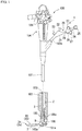
Fig. 1 is an overall view showing a state when an endoscopic treatment tool according to a first embodiment of the present invention is attached to an endoscope. -
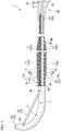
Fig. 2 is a sideview showing a partial cross section of the endoscopic treatment tool. -
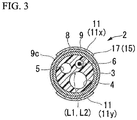
Fig. 3 is a view showing a cross section taken along A1-A1 line inFig. 2 . -
Fig. 4 is a sideview showing a partial cross section of a pre-curved shape portion of the endoscopic treatment tool when the pre-curved shape portion is in a curved state. -
Fig. 5 is a view showing a cross section taken along A2-A2 line inFig. 4 . -
Fig. 6 is a schematic view showing the endoscopic treatment tool in an image by the endoscope in a state when the endoscopic treatment tool is inserted into the bile duct via the duodenal papilla. -
Fig. 7 is a schematic view showing the endoscopic treatment tool in the state when the endoscopic treatment tool is inserted into the bile duct via the duodenal papilla. -
Fig. 8 is a schematic view showing the endoscopic treatment tool in the image by the endoscope in a state when a distal end of a shaft of the endoscopic treatment tool reaches a branching region of common bile duct and cystic duct. -
Fig. 9 is a schematic view showing the endoscopic treatment tool in the state when the distal end of the shaft of the endoscopic treatment tool reaches the branching region of the common bile duct and the cystic duct. -
Fig. 10 is a schematic view showing the endoscopic treatment tool in the image by the endoscope in a state when a distal end of a sheath of the endoscopic treatment tool is rotated in the branching region of the common bile duct and the cystic duct. -
Fig. 11 is a view showing the endoscopic treatment tool in the state when the distal end of the sheath of the endoscopic treatment tool is rotated in the branching region of the common bile duct and the cystic duct. -
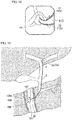
Fig. 12 is a schematic view showing the endoscopic treatment tool in the image by the endoscope in a state when the distal end of the sheath of the endoscopic treatment tool reaches a branching region of intrahepatic bile ducts. -
Fig. 13 is a schematic view showing the endoscopic treatment tool in the state when the distal end of the sheath of the endoscopic treatment tool reaches the branching region of the intrahepatic bile ducts. -
Fig. 14 is a schematic view showing the endoscopic treatment tool in the image by the endoscope in the state when the distal end of the sheath of the endoscopic treatment tool is rotated in the branching region of the intrahepatic bile ducts. -
Fig. 15 is a schematic view showing the endoscopic treatment tool in the state when the distal end of the sheath of the endoscopic treatment tool is rotated in the branching region of the intrahepatic bile ducts. -
Fig. 16 is a side view showing another configuration example of the endoscopic treatment tool. -
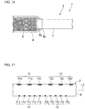
Fig. 17 is a side view showing a further configuration example of the endoscopic treatment tool. -
Fig. 18 is a side view showing a further configuration example of the endoscopic treatment tool. -
Fig. 19 is a side view showing a further configuration example of the endoscopic treatment tool. -
Fig. 20 is a side view showing a cross section of an endoscopic treatment tool according to a second embodiment of the present invention. -
Fig. 21 is a view showing a cross section taken along A7-A7 line inFig. 20 . -
Fig. 22 is a view showing a cross section taken along A8-A8 line inFig. 20 . -
Fig. 23 is a view showing a cross section taken along A9-A9 line inFig. 20 . -
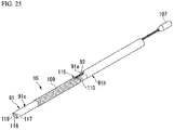
Fig. 24 is a perspective view showing a multi-lumen tube and a torque transmitting member which are disassembled used in the endoscopic treatment tool. -
Fig. 25 is a perspective view showing a state of attaching the torque transmitting member to the multi-lumen tube. -
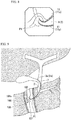
Fig. 26 is a view showing procedures using the endoscopic treatment tool. - A first embodiment of the present invention will be described.
Fig. 1 is an overall view showing a state when an endoscopic treatment tool (including a catheter used for an insertion into the bile duct) according to the present embodiment is inserted into a treatment tool channel of an endoscope.Fig. 2 is a sideview showing a partial cross section of the endoscopic treatment tool.Fig. 3 is a view showing a cross section taken along A1-A1 line inFig. 2 .Fig. 4 is a sideview showing a partial cross section of a pre-curved shape portion of the endoscopic treatment tool when the pre-curved shape portion is in a curved state.Fig. 5 is a view showing a cross section taken along A2-A2 line inFig. 4 . - As shown in
Fig. 1 andFig. 2 , anendoscopic treatment tool 1 according to the present embodiment has ashaft 2. - As shown in
Fig. 2 , theshaft 2 has adistal end 2a and aproximal end 2b, and theshaft 2 extends along a longitudinal axis L. - As shown in
Fig. 2 andFig. 3 , theshaft 2 has alumen tube 3 and abraid 8. - The
lumen tube 3 is a tube that has at least one lumen. This lumen is used for various usages such as for inserting a guide wire, for supplying liquid such as a contrast media, and the like. For example, as shown inFig. 3 , thelumen tube 3 may be amulti-lumen tube 3x. Themulti-lumen tube 3x is configured to have three lumens (afirst lumen 4, asecond lumen 5, and a third lumen 6). - In a case when the
multi-lumen tube 3x is adopted as thelumen tube 3, the usage of each lumen is determined as follows. - The
first lumen 4 is a lumen for inserting a medical guide wire (not shown). - The
second lumen 5 is a lumen for transmitting the liquid such as the contrast media from theproximal end 2b to thedistal end 2a of theshaft 2. - The
third lumen 6 may be used as a lumen for inserting a treatment portion as well as for inserting the guide wire and transmitting the liquid such as the contrast media. - As shown in
Fig. 2 andFig. 3 , thebraid 8 is a tubular member surrounding thelumen tube 3. Thebraid 8 is disposed in the vicinity of adistal end 3a of thelumen tube 3. Adistal end 8a of thebraid 8 according to the present embodiment is positioned apart away from thedistal end 3a by a predetermined distance at aproximal end 3b side of thelumen tube 3. - The
braid 8 is formed in a tubular shape by braiding a bundle of thin wires that are formed from stainless steel in a lattice shape, for example. However, thebraid 8 is not limited thereto. Thebraid 8 can be formed in a tubular shape by winding a stainless wire or a stainless strip in a single coil shape or a multi-threaded coil shape, and thebraid 8 can be formed in a tubular shape by winding a single coil or a multi-threaded coil alternatively in different winding directions to form a multi-layer structure. In thebraid 8, theshaft 2 is strengthened such that a rotation of theshaft 2 at thedistal end 8a of thebraid 8 can suitably follow a rotation of theshaft 2 at theproximal end 8b of thebraid 8. Thebraid 8 is configured to realize both objects in a predetermined region in the vicinity of the distal end of theshaft 2 such that theshaft 2 has flexibility and the rotation of thedistal end 2a of theshaft 2 suitably follows a rotating operation of the operator with respect to theshaft 2. According to the present embodiment, the predetermined region in the vicinity of the distal end of theshaft 2 refers to a region that is assumed to be inserted into the bile duct or the pancreatic duct during procedures using theendoscopic treatment tool 1 according to the present embodiment. - In the present embodiment, as shown in
Fig. 2 andFig. 3 , a longitudinal axis L2 of thebraid 8 is coaxial with the longitudinal axis L1 of theshaft 2. A length of thebraid 8 in a direction along the longitudinal axis L2 of thebraid 8 is determined by considering that a part at a side of theproximal end 8b of thebraid 8 is always positioned between the duodenal papilla and the inside of the duodenum, during the procedure of inserting theshaft 2 from thedistal end 2a of theshaft 2 into the bile duct and the pancreatic duct. For example, theproximal end 8b of thebraid 8 is positioned at a position equal to or more than 15 centimeters spaced away from thedistal end 2a of theshaft 2 at theproximal end 2b side. That is, during the procedure of inserting theshaft 2 from thedistal end 2a of theshaft 2 into the bile duct and the pancreatic duct via the duodenal papilla, the region of theshaft 2 inserted into the inside of the bile duct and the pancreatic duct has a high followability with respect to the rotating operation. - As shown in
Fig. 3 ,Fig. 4 andFig. 16 , acoating member 9 may be configured to coat an outer circumferential surface of thebraid 8. An outercircumferential surface 9c of thecoating member 9 is configured to form the outercircumferential surface 2c of theshaft 2 between thedistal end 9a and theproximal end 9b of thecoating member 9. In this case, thecoating member 9 is configured to at least coat thebraid 8 between thedistal end 8a of thebraid 8 to theproximal end 8b of thebraid 8. Thecoating member 9 is transparent or semi-transparent such that it is possible to capture an image of the outer circumferential surface of thebraid 8 by an imaging portion (observation optical system) 102 of theendoscope 100. - On the outer circumferential surface of the
braid 8, adistal indicator 11 and a proximal indictor are disposed to be capable of being captured by theimaging portion 102 of theendoscope 100. Even in the case when thecoating member 9 is provided on the outer circumferential surface of thebraid 8, as shown inFig. 16 , thedistal indicator 11 and theproximal indicator 12 can be captured by theimaging portion 102 since thecoating member 9 is transparent or semitransparent. - It is not necessary for the
distal indicator 11 and theproximal indicator 12 to be disposed on the outer circumferential surface of thebraid 8. For example, thedistal indicator 11 and theproximal indicator 12 can be disposed on the outercircumferential surface 9c of thecoating member 9. - In the present embodiment, the
distal indicator 11 and theproximal indicator 12 disposed on the outer circumferential surface of thebraid 8, and thedistal indicator 11 and theproximal indicator 12 disposed on the outercircumferential surface 9c of thecoating member 9 configured to coat the outer circumferential surface of thebraid 8 are described as configurations disposed on the outer circumferential surface of thebraid 8. - The
distal indicator 11 is configured in considering that when theshaft 2 is rotated in the state in which thedistal end 2a of theshaft 2 is inserted into the bile duct and the pancreatic duct via the duodenal papilla, thedistal indicator 11 is protrudes from the duodenal papilla to be exposed in the duodenum. Specifically, in the state in which theshaft 2 is raised by a raisingstand 106 of theendoscope 100 and when thedistal end 2a of theshaft 2 is positioned in a branching region of the common bile duct and the cystic duct inside the body as shown inFig. 9 , thedistal indicator 11 is configured to be positioned in a field of view of the imaging portion (observation optical system) 102 as shown inFig. 8 . In this case, thedistal indicator 11 is disposed at least between a position of 5 centimeters from the distal end of theshaft 2 and a position of 10 centimeters from the distal end of theshaft 2. Also, thedistal indicator 11 disposed between the position of 5 centimeters from the distal end of theshaft 2 and the position of 10 centimeters from the distal end of theshaft 2 may be disposed across the entire region or disposed in a local (partial) region. - The
distal indicator 11 is preferable to extend along the direction of the longitudinal axis L1 of theshaft 2. That is, at least part of thedistal indicator 11 is preferable to extend in a direction intersecting with the winding direction of the wires forming thebraid 8. - In a case in which the
distal indicator 11 is formed using a colored marker due to paint or the like, it is preferable to make thedistal indicator 11 have a different color scheme from that of the outer circumferential surface of thebraid 8. For example, when the color of the outer circumferential surface of thebraid 8 is grey, thedistal indicator 11 is preferable to be green or blue. - The
proximal indicator 12 is also configured in considering that when theshaft 2 is rotated in the state in which thedistal end 2a of theshaft 2 is inserted into the bile duct and the pancreatic duct via the duodenal papilla, theproximal indicator 12 protrudes from the duodenal papilla to be exposed in the duodenum. Specifically, in the state in which theshaft 2 is raised by the raisingstand 106 of theendoscope 100, and when thedistal end 2a of theshaft 2 is positioned in a branching region of the left hepatic duct and right hepatic duct as shown inFig. 13 , theproximal indicator 12 is configured to be positioned in the field of view of the imaging portion (observation optical system) 102 as shown inFig. 12 . In this case, theproximal indicator 12 is disposed at least between a position of 10 centimeters from the distal end of theshaft 2 and a position of 15 centimeters from the distal end of theshaft 2. Also, theproximal indicator 12 disposed between the position of 10 centimeters from the distal end of theshaft 2 and the position of 15 centimeters from the distal end of theshaft 2 may be disposed across the entire region or disposed in a local (partial) region. - In a case when the
shaft 2 is inserted into the duodenal papilla in a state in which the duodenal papilla is captured in the field of view of theimaging portion 102 of theendoscope 100, it is necessary to largely bend theshaft 2 in a small curvature radius by the raisingstand 106 of theendoscope 100. At this time, theshaft 2 bent by the raisingstand 106 is largely bent in a smaller curvature radius than that of achannel 51 which is bent due to the bending of theinsertion body 101 of theendoscope 100. - In the present embodiment, the
proximal indicator 12 is configured such that in the state in which theproximal indicator 12 is positioned in the field of view of theimaging portion 102, theproximal end 8b of thebraid 8 is positioned at a more proximal side of theshaft 2 than aproximal end 106a of the raisingstand 106. That is, it is configured that thebraid 8 which has superior flexibility and torque transmissibility is positioned in the region bent by the raisingstand 106. - Accordingly, the torque transmissibility from the proximal end side to the distal end side of the
shaft 2 can be maintained while maintaining the state in which theproximal indicator 12 is captured in the field of view of the imaging portion of theendoscope 100. - The
proximal indicator 12 is preferable to extend along the direction of the longitudinal axis L1 of theshaft 2. That is, at least part of theproximal indicator 12 is preferable to extend in a direction intersecting with the winding direction of the wires forming thebraid 8. - In a case in which the
proximal indicator 12 is formed using a colored marker due to paint or the like, it is preferable to make theproximal indicator 12 to have a different color scheme from that of the outer circumferential surface of thebraid 8. For example, when the color of the outer circumferential surface of thebraid 8 is grey, theproximal indicator 12 is preferable to be green or blue. - The
distal indicator 11 and theproximal indicator 12 are preferable to be disposed in a substantial straight line. - The
distal indicator 11 is more preferable configured to have a firstdistal indicator 11x and a seconddistal indicator 11y. - The
proximal indicator 12 may be configured to have a firstproximal indicator 12x and a secondproximal indicator 12y. - As shown in
Fig. 2 andFig. 4 , the firstdistal indicator 11x and the firstproximal indicator 12x are configured to extend along the longitudinal axis L1 of theshaft 2. The firstdistal indicator 11x and the firstproximal indicator 12x are disposed in a region equal to or less than half of the outer circumferential surface of theshaft 2 in the circumferential direction of theshaft 2. Either of a width of the firstdistal indicator 11x or a width of the firstproximal indicator 12x is preferable to be a constant value when measured in the circumferential direction of theshaft 2 along the outercircumferential surface 2c of theshaft 2. - The second
distal indicator 11y and the secondproximal indicator 12y, as the same with the firstdistal indicator 11x and the firstproximal indicator 12x, are configured to extend along the longitudinal axis L1 of theshaft 2. The seconddistal indicator 11y and the secondproximal indicator 12y are disposed in a region equal to or less than half of the outer circumferential surface of theshaft 2 in the circumferential direction of theshaft 2. Either of a width of the seconddistal indicator 11y or the secondproximal indicator 12y is preferable to be a constant value when measured in the circumferential direction of theshaft 2 along the outer circumferential surface of theshaft 2. - As shown in
Fig. 3 , the seconddistal indicator 11y is disposed at an opposite side with respect to the firstdistal indicator 11x in a radius direction of theshaft 2. As the same, the secondproximal indicator 12y is disposed in an opposite side with respect to the firstproximal indicator 11y in the radius direction of theshaft 2. Specifically, the seconddistal indicator 11y is disposed at the opposite side with respect to the firstdistal indicator 11x so as to sandwich the longitudinal axis (center line) L1 of theshaft 2. The secondproximal indicator 12y is disposed at the opposite side with respect to the firstproximal indicator 12x so as to sandwich the longitudinal axis (center line) L1 of theshaft 2. - For example, a proximal end 12b of the
proximal indicator 12 may be at a position spaced away from theproximal end 2b of theshaft 2 at thedistal end 2a side. For example, adistal end 11a of thedistal indicator 11 may be at a position spaced away from thedistal end 2a of theshaft 2 at a side of theproximal end 2b. - The
distal indicator 11 may be in the vicinity of thedistal end 8a of thebraid 8, for example, thedistal indicator 11 may be at a position slightly spaced away from thedistal end 8a of thebraid 8 at the side of theproximal end 2b of theshaft 2. - As shown in
Fig. 4 , for example, the width of thedistal indicator 11 measured in the circumferential direction of theshaft 2 along the outer circumferential surface of theshaft 2, may be equal to the width of theproximal indicator 12 measured in the circumferential direction of theshaft 2 along the outer circumferential surface of theshaft 2. - In the present embodiment, the first
distal indicator 11x and the seconddistal indicator 11y are not continuous in the circumferential direction of theshaft 2. That is, in the circumferential direction of theshaft 2, there is a gap generated between the firstdistal indicator 11x and the seconddistal indicator 11y. Also, the firstproximal indicator 12x and the secondproximal indicator 12y are not continuous in the circumferential direction of theshaft 2. That is, there is a gap generated between the firstproximal indicator 12x and the secondproximal indicator 12y. - The first
distal indicator 11x and the seconddistal indicator 11y are not limited thereto . The firstdistal indicator 11x and the seconddistal indicator 11y may be disposed in the circumferential direction of theshaft 2 so as to be adjacent to each other without any gap. In this case, when the paint colored marker is used, the color of the firstdistal indicator 11x is different from the color of the seconddistal indicator 11y such that a boundary of the firstdistal indicator 11x and the seconddistal indicator 11y can be recognized on the image captured by the endoscope. - The first
proximal indicator 12x and the secondproximal indicator 12y are the same as the firstdistal indicator 11x and the seconddistal indicator 11y which are described above. That is, the firstproximal indicator 12x and the secondproximal indicator 12y may be disposed in the circumferential direction of theshaft 2 so as to be adjacent to each other without any gap. When the paint colored marker is used, the color of the firstproximal indicator 12x is different from the color of the secondproximal indicator 12y such that a boundary of the firstproximal indicator 12x and the secondproximal indicator 12y can be recognized on the image captured by the endoscope. - The
endoscopic treatment tool 1 according to the present embodiment may have apre-curved shape portion 7 having a predetermined curved shape that is disposed in the vicinity of adistal end 3a of thelumen tube 3 as shown inFig. 4 . In this case, for example, thepre-curved shape portion 7 is disposed between thedistal end 11a of thedistal indicator 11 and thedistal end 2a of theshaft 2. - The
pre-curved shape portion 7 is configured to have a predetermined curving habit with respect to thelumen tube 3. That is, thepre-curved shape portion 7 has a restoring force so as to restore to the predetermined curved shape . Accordingly, after thepre-curved shape portion 7 is deformed to a straight shape when being applied with an external force, once the external force is withdrawn, thepre-curved shape portion 7 can restore to the original curved shape. - Furthermore, the curved shape of the
pre-curved shape portion 7 is configured in consideration of changing the orientation of theshaft 2 such that thedistal end 2a of theshaft 2 can be easily inserted into the duodenal papilla, in a case when theshaft 2 is protruded from the distal end of atreatment tool channel 103 of a sideview type endoscope 100 (seeFig.1 ). - When the
pre-curved shape portion 7 is disposed in the vicinity of thedistal end 3a of thelumen tube 3, as shown inFig. 4 , thedistal end 8a of thebraid 8 is positioned at a side closer to theproximal end 3b than theproximal end 7b of thepre-curved shape portion 7. - As shown in
Fig. 4 andFig. 5 , the firstdistal indicator 11x and the firstproximal indicator 12x are associated with the shape of thepre-curved shape portion 7 of theshaft 2. Thedistal end 2a of theshaft 2 is positioned in the range defined by the width of the firstdistal indicator 11x and the firstproximal indicator 12x, in a front view along the direction of the longitudinal axis L1 of theshaft 2. That is, in the front view along the direction of the longitudinal axis L1 of theshaft 2a, a direction X1 orthogonal to the longitudinal axis L1 of theshaft 2 and from the longitudinal axis L1 toward the firstdistal indicator 11x and the firstproximal indicator 12x is substantially coincides with the bending direction of thepre-curved shape portion 7. - Further, as shown in
Fig. 4 andFig. 5 , the seconddistal indicator 11y and the secondproximal indicator 12y are associated with the shape of thepre-curved shape portion 7 of theshaft 2. Thedistal end 2a of theshaft 2 is positioned in the range defined by the width of the seconddistal indicator 11y and the secondproximal indicator 12y, in a front view along the direction of the longitudinal axis L1 of theshaft 2. That is, in the front view along the direction of the longitudinal axis L1 of theshaft 2a, a direction X2 orthogonal to the longitudinal axis L1 of theshaft 2 and from the longitudinal axis L1 toward the seconddistal indicator 11y and the secondproximal indicator 12y is opposite to the bending direction of thepre-curved shape portion 7. - As shown in
Fig. 2 , the endoscopic treatment tool according to the present embodiment may have atreatment portion 13 and anoperation portion 20. Thetreatment portion 13 is provided at the distal side of theshaft 2, and theoperation portion 20 is provided at the proximal side of theshaft 2. Thetreatment portion 13 has aknife fixing portion 18 fixed to the vicinity of thedistal end 3a of themulti-lumen tube 3x (knife support portion 14) and aknife wire 15 connected to theknife fixing portion 18. - In this case, the
third lumen 6 may be used as the lumen into which theknife wire 15 of thetreatment portion 13 is inserted. - As shown in
Fig. 2 andFig. 3 , two throughholes third lumen 6 so as to be spaced away from each other in the direction of the longitudinal axis L1 of theshaft 2. Either of the two throughholes third lumen 6 and opens on the outer circumferential surface of themulti-lumen tube 3x. Theknife wire 15 is inserted into the two throughholes holes hole 6a formed at thedistal end 2a side of theshaft 2 is at a position slightly away from thedistal end 2a of theshaft 2 at theproximal end 2b side. In the two throughholes hole 6b formed at theproximal end 2b side of theshaft 2 is at a position at a side closer to thedistal end 2a of theshaft 2 than thedistal end 8a of thebraid 8. A distance between the two throughholes shaft 2 may be about 30 millimeters, for example. - The openings of the two through
holes pre-curved shape portion 7. - For example, in the direction along the longitudinal axis L1 of the
shaft 2, thedistal end 11a of thedistal indicator 11 is positioned in the vicinity of the proximal side throughhole 6b formed on themulti-lumen tube 3, and thedistal end 11a of thedistal indicator 11 is more proximal than the throughhole 6b. - The
knife wire 15 has aknife portion 16 and aconductive wire portion 17, wherein theknife portion 16 is connected to theknife fixing portion 18 and disposed outside themulti-lumen tube 3x, and theconductive wire portion 17 is configured to extend to theproximal end 2b of theshaft 2 via thethird lumen 6 of themulti-lumen tube 3x. Theknife wire 15 is connected to themulti-lumen tube 3x by theknife fixing portion 18 at the distal side throughhole 6a of the two throughholes distal end 3a of themulti-lumen tube 3x. That is, a distal end of theknife wire 15 is fixed to the vicinity of the distal end of the shaft 2 (knife support portion 14) by theknife fixing portion 18. Theknife portion 16 is exposed to the outside of themulti-lumen tube 3x in the region between the two throughholes distal end 3a of themulti-lumen tube 3x. - In the present embodiment, the
knife portion 16 and theconductive knife portion 17 are configured by theknife wire 15 which is formed by a continuous metal wire. Accordingly, there is not a clear boundary between theknife portion 16 and theconductive knife portion 17. In the present embodiment, theknife portion 16 refers to the part exposed to the outside of themulti-lumen tube 3x between the two throughholes distal end 3a of themulti-lumen tube 3x. - Between the two through holes formed on the
multi-lumen tube 3x, theknife wire 15 is disposed at a position spaced away from a center (the position of the longitudinal axis L1) of theshaft 2 in a section orthogonal to the longitudinal axis L1 of theshaft 2. The distal end portion of theshaft 2 including the distal throughhole 6a is actively bendable by pulling theknife wire 15 at the operation portion side. - In the front view from the direction along the longitudinal axis L1 of the
shaft 2, the distal end portion bent by pulling theknife wire 15 at the operation portion side is substantially coincided with the position where theknife portion 16 is exposed from theshaft 2. Also, in a projection plane formed on a plane orthogonal to the longitudinal axis L1 of theshaft 2, thedistal indicator 11 and theproximal indicator 12 substantially coincides with the position where theknife portion 16 is exposed from theshaft 2. - As shown in
Fig. 1 andFig. 2 , theoperation portion 20 has amain body 21 and aslider 26. - The
main body 21 has aguide wire port 22, aliquid port 23, and anaxial portion 24. - The
guide wire port 22 communicates with thefirst lumen 4 of theshaft 2. - The
liquid port 23 communicates with thesecond lumen 5 of theshaft 2. - The
axial portion 24 is formed in a rod shape and theaxial portion 24 has afinger hook ring 25 at an end. - The
slider 26 is connected to theaxial portion 24 so as to be capable of advancing and retracting with respect to theaxial portion 24. Theslider 26 has afinger hook ring 27 and aplug 28. - The
plug 28 provided at theslider 26 is connected to the proximal end 15b of the knife wire 15 (theproximal end 17b of the conductive wire portion 17). Accordingly, it is possible to flow a high-frequency current to theconductive wire potion 17 through theknife portion 16 by connecting theplug 28 with a high-frequency power supply (not shown). - The
endoscope 100 used with theendoscopic treatment tool 1 according to the present embodiment will be described. - The
endoscope 100 used with theendoscopic treatment tool 1 is a flexible side-view type endoscope, as shown inFig. 1 . For example, theendoscope 100 has an elongatedinsertion body 101, and anoperation body 104 disposed at an end portion of theinsertion body 101. - A side-view
type imaging portion 102 is disposed at adistal end 101a of theinsertion body 101 such that a center of a field of view is directed to a direction intersecting a center line of theinsertion body 101. Also, adistal opening 103a of atreatment tool channel 103 for inserting theshaft 2 of theendoscopic treatment tool 1 is formed at thedistal end 101a of theinsertion body 101. - The
operation body 104 has aknob 105 for controlling the bending operation of theinsertion body 101 and aproximal opening 103b of thetreatment tool channel 103. - The effect of the
endoscopic treatment tool 1 according to the present embodiment will be described. -
Fig. 6 is a schematic view showing the endoscopic treatment tool in an image captured by the endoscope in a state when the endoscopic treatment tool is inserted into the bile duct via the duodenal papilla.Fig. 7 is a schematic view showing the endoscopic treatment tool in the state when the endoscopic treatment tool is inserted into the bile duct via the duodenal papilla. - In the present embodiment, the operator (for example, a scopist) inserts the
endoscope 100 into the mouth, and then guides thedistal end 101a of theinsertion body 101 of theendoscope 100 to the vicinity of the duodenal papilla (shown as the reference sign P in the figure) (seeFig. 7 ). - During the procedure of using the
endoscopic treatment tool 1, the operator (for example, the surgeon) inserts theshaft 2 of theendoscopic treatment tool 1 into thetreatment tool channel 103 of theendoscope 100, protrudes thedistal end 2a of theshaft 2 from thedistal opening 103a of thetreatment tool channel 103, and inserts thedistal end 2a of theshaft 2 into the duodenal papilla. - As shown in
Fig. 6 , the position and the orientation of thedistal end 2a of theendoscopic treatment tool 1 is observable using theimaging portion 102 of theendoscope 100 until theshaft 2 enters the duodenal papilla. However, after theshaft 2 enters the duodenal papilla, the part of theshaft 2 that has entered the duodenal papilla cannot be observed using theimaging portion 102 of theendoscope 100. - The operator can observe the
shaft 2 that enters the bile duct and the pancreatic duct using an X-ray image. For example, as shown inFig. 7 , the operator can observe a movement of theshaft 2 using the X-ray image. On the X-ray image, the member having radiopacity (for example, theknife wire 15 made from metal) can be clearly visually confirmed. Also, it is possible to understand the position and the orientation of theshaft 2 using the X-ray image if theshaft 2 is made from the material having radiopacity. - However, in the case of rotating the
shaft 2 about the longitudinal axis L1 of theshaft 2 as the rotation center, it is difficult to understand how much thedistal end 2a of theshaft 2 has rotated by confirming the X-ray image. Also, in the case of rotating theshaft 2 protruding from theproximal opening 103b formed at theoperation body 104 of theendoscope 100, an operating amount of rotating theshaft 2 does not coincide with a rotation movement amount of thedistal end 2a of theshaft 2 due to the flexibility of theshaft 2. In the entire length of theshaft 2, the range from theproximal end 2b of theshaft 2 to theproximal end 8b of thebraid 8 is elongated such that a discrepancy between the operating amount of rotating theshaft 2 and the rotation movement amount of thedistal end 2a of theshaft 2 is large. In the range from theproximal end 8b of thebraid 8 to thedistal end 2a of theshaft 2, since the range from theproximal end 8b of thebraid 8 to thedistal end 2a of theshaft 2 is shorter than the range from theproximal end 2b of theshaft 2 to theproximal end 8b of thebraid 8 and the rotation followability is enhanced by thebraid 8, the discrepancy between the operating amount of rotating theshaft 2 and the rotation movement amount of thedistal end 2a of theshaft 2 is small. - In the
endoscopic treatment tool 1 according to the present embodiment, thedistal indicator 11 and theproximal indicator 12 are provided such that it is easy to assume the rotation position of thedistal end 2a of theshaft 2 based on the positions of thedistal indicator 11 and theproximal indicator 12, even if the orientation of thedistal end 2a of theshaft 2 cannot be understood using theimaging portion 102 of theendoscope 100. -
Fig. 8 is a schematic view showing the endoscopic treatment tool in the image captured by the endoscope in a state when a distal end of a shaft of the endoscopic treatment tool reaches a branching region of common bile duct and cystic duct.Fig. 9 is a schematic view showing the endoscopic treatment tool in the state when the distal end of the shaft of the endoscopic treatment tool reaches the branching region of the common bile duct and the cystic duct.Fig. 10 is a schematic view showing the endoscopic treatment tool in the image captured by the endoscope in a state when a distal end of a sheath of the endoscopic treatment tool is rotated in the branching region of the common bile duct and the cystic duct.Fig. 11 is a view showing the endoscopic treatment tool in the state when the distal end of the sheath of the endoscopic treatment tool is rotated in the branching region of the common bile duct and the cystic duct. - As shown in
Fig. 9 , after thedistal end 2a of theshaft 2 reaches the branching region of the common bile duct and the cystic duct, there are a case of inserting theshaft 2 into the intrahepatic bile duct through the common bile duct and a case of inserting theshaft 2 into the cystic duct. If theshaft 2 is inserted into the duct with the original state, due to a meandering state of theshaft 2 in the duct, theshaft 2 may be inserted into a different duct from the duct into which theshaft 2 is intended to be inserted among the branched ducts. In this case, it is necessary for the operator to rotate theshaft 2 for directing the orientation of thedistal end 2a of theshaft 2 toward the duct into which theshaft 2 is intended to be inserted (the intrahepatic bile duct side or the cystic duct side). - As shown in
Fig. 10 , once theshaft 2 is rotated, as shown inFig. 11 , the direction of thedistal end 2a of theshaft 2 can be changed. Accordingly, the operator can direct thedistal end 2a of theshaft 2 toward the direction of the duct into which thedistal end 2a of theshaft 2 is intended to be inserted. - In the
endoscopic treatment tool 1 according to the present embodiment, when thedistal end 2a of theshaft 2 is positioned at the branched region of the common bile duct and the cystic duct, since thedistal indicator 11 is protruded from the duodenal papilla into the duodenum, the duodenal papilla and the vicinity thereof can be captured in the field of view of theimaging portion 102. Accordingly, the operator can understand the rotation state of theshaft 2 by confirming the positions of thedistal indicator 11, more specifically, the firstdistal indicator 11x and the seconddistal indicator 11y, in the circumferential direction using the image captured by the endoscope. -
Fig. 13 is a schematic view showing the endoscopic treatment tool in the state when the distal end of the sheath of the endoscopic treatment tool reaches the branching region of the intrahepatic bile ducts.Fig. 14 is a schematic view showing the endoscopic treatment tool in the image by the endoscope in the state when the distal end of the sheath of the endoscopic treatment tool is rotated in the branching region of the intrahepatic bile ducts .Fig. 15 is a schematic view showing the endoscopic treatment tool in the state when the distal end of the sheath of the endoscopic treatment tool is rotated in the branching region of the intrahepatic bile ducts. - Once the
distal end 2a of theshaft 2 is moved toward the intrahepatic bile duct, thedistal end 2a of theshaft 2 reaches the branching region of the intrahepatic bile ducts. As shown inFig. 13 , after thedistal end 2a of theshaft 2 reaches the branching region of the left hepatic duct and the right hepatic duct, there are a case of inserting theshaft 2 into the left hepatic duct and a case of inserting theshaft 2 into the right hepatic duct. If theshaft 2 is inserted into the duct in the original state, due to the meandering state of theshaft 2 in the duct, theshaft 2 may be inserted into a different duct from the duct into which theshaft 2 is intended to be inserted among the branched ducts. In this case, it is necessary for the operator to rotate theshaft 2 for directing the orientation of thedistal end 2a of theshaft 2 toward the duct into which theshaft 2 is intended to be inserted (the left hepatic duct side or the right hepatic duct side). - As shown in
Fig. 14 , once theshaft 2 is rotated, as shown inFig. 15 , the direction of thedistal end 2a of theshaft 2 can be changed. Accordingly, the operator can direct thedistal end 2a of theshaft 2 toward the direction of the duct into which thedistal end 2a of theshaft 2 is intended to be inserted. - In the
endoscopic treatment tool 1 according to the present embodiment, when thedistal end 2a of theshaft 2 is positioned at the branched region of the left hepatic duct and the right hepatic duct, since theproximal indicator 12 is protruded from the duodenal papilla into the duodenum so as to be captured in the field of view of theimaging portion 102. Accordingly, the operator can understand the rotation state of theshaft 2 by confirming the positions of theproximal indicator 12, more specifically, the firstproximal indicator 12x and the secondproximal indicator 12y, in the circumferential direction using the image captured by the endoscope. - In the
shaft 2 according to the present embodiment, thedistal indicator 11 and theproximal indicator 12 are provided on the outer circumferential surface of thebraid 8 such that the region where thefirst indicator 11 and theproximal indicator 12 are disposed has superior rotation followability. Accordingly, the discrepancy between the rotation amount of thedistal indicator 11 and the rotation amount of thedistal end 2a of theshaft 2 is small. Also, the discrepancy between the rotation amount of theproximal indicator 12 and the rotation amount of thedistal end 2a of theshaft 2 is small. In other words, the rotation amounts of thedistal indicator 11 and theproximal indicator 12 can be presumed as the rotation amount of thedistal end 2a of theshaft 2. - As a result, the operator can assume how much the
distal end 2a of theshaft 2 has rotated with higher accuracy by observing the image captured by the endoscope regarding how much thedistal indicator 11 and theproximal indicator 12 have rotated in correspondence with the operation of rotating theshaft 2. - The position and the orientation of the
shaft 2 can be assumed with higher accuracy by confirming the X-ray image in combination. - As shown in
Fig. 4 , in a case in which thepre-curved shape portion 7 is disposed in the vicinity of thedistal end 3a of thelumen tube 3, the same effect can be achieved. Further, in a case in which thetreatment portion 13 is disposed at the distal end side of theshaft 2 and theoperation portion 20 is disposed at the proximal end side of theshaft 2, the same effect can be achieved. - Each indicator is associated with the shape of the
pre-curved shape portion 7 such that the firstdistal indicator 11x and the firstproximal indicator 12x are corresponding to the bending direction of thepre-curved shape portion 7 and the seconddistal indicator 11y and the secondproximal indicator 12y are corresponding to the opposite direction of the bending direction of thepre-curved shape portion 7. As a result, according to theendoscopic treatment tool 1 according to the present embodiment, it is easy to understand the orientation of theendoscopic treatment tool 1 inserted into the bile duct and the pancreatic duct using the image captured by the endoscope, and thus it is possible to minimize the operation of rotating theshaft 2. - Since the bending shape of the
pre-curved shape portion 7 is associated with thedistal indicator 11 and theproximal indicator 12, in the state when theshaft 2 is inserted into the bile duct and the pancreatic duct through the duodenal papilla, it is easy for the operator to understand the direction of thedistal end 2a of theshaft 2 by considering the positions of thedistal indicator 11 and theproximal indicator 12 on the image captured by the endoscope, and the direction of theshaft 2 on the X-ray image. - As described above, according to the
endoscopic treatment tool 1 of the present embodiment, it is easy to understand the orientation of theendoscopic treatment tool 1 using the image captured by the endoscope. - The embodiments of the invention have been described above with reference to the drawings, but specific structures of the invention are not limited to the embodiments and may include various modifications without departing from the scope of the invention.
- For example, as shown in
Fig. 17 , thedistal indicator 11 and theproximal indicator 12 according to the above embodiment may be discontinuous along the longitudinal direction of theshaft 2. For example, thedistal indicator 11 and theproximal indicator 12 may be configured by arranging a plurality of dots at intervals in the direction along the longitudinal axis L1 of theshaft 2 to form a dot pattern. In this case, the dot pattern may be at even intervals, and the dot pattern may be at uneven intervals. - As shown in
Fig. 18 , in the case when each of the firstdistal indicator 11x and the seconddistal indicator 11y has a width equal to half of theshaft 2 in the circumferential direction of theshaft 2 respectively and the firstdistal indicator 11x and the seconddistal indicator 11y are adjacent to each other, either of the firstdistal indicator 11x or the seconddistal indicator 11y (the firstdistal indicator 11x inFig. 18 ) may be colored with a different color from that of the material of theshaft 2, and the other (the seconddistal indicator 11y inFig. 18 ) may be formed from the material of the shaft 2 (the color of thecoating member 9 inFig. 18 ). That is, the part on the outer circumferential surface of theshaft 2 that is colored becomes the firstdistal indicator 11x, and the part that is not colored becomes the seconddistal indicator 11y. The firstproximal indicator 12x and the secondproximal indicator 12y may have the same configurations. - As shown in
Fig. 19 , half of theshaft 2 in the circumferential direction of theshaft 2 is colored with a first color (reference sign 10 inFig. 19 ), and the other half of theshaft 2 in the circumferential direction of theshaft 2 is colored with another color different from the first color (for example, the color of the coating member 9), thus the boundaries of the first color and the other color may be defined as the firstdistal indicator 11x and the seconddistal indicator 11y. The firstproximal indicator 12x and the secondproximal indicator 12y may have the same configurations. - The
distal indicator 11 and theproximal indicator 12 may be configured by using the paint having radiopacity. In this case, the distal indicator and the proximal indicator can be confirmed on the X-ray image such that the torsion state of the sheath inside the bile duct and the pancreatic duct is easy to understand. - Next, a second embodiment of the present invention will be described by referring to
Fig. 20 to Fig. 26 , however, elements same as that of the first embodiment will be affixed with the same reference signs of the first embodiment, and only the different configurations will be described.Fig. 20 is a side view showing a cross section of an endoscopic treatment tool according to a second embodiment of the present invention.Fig. 21 is a view showing a cross section taken along A7-A7 line inFig. 20 .Fig. 22 is a view showing a cross section taken along A8-A8 line inFig. 20 .Fig. 23 is a view showing a cross section taken along A9-A9 line inFig. 20 .Fig. 24 is a perspective view showing a multi-lumen tube and a torque transmitting member which are disassembled used in the endoscopic treatment tool.Fig. 25 is a perspective view showing a state of attaching the torque transmitting member to the multi-lumen tube.Fig. 26 is a view showing procedures using the endoscopic treatment tool. - As shown from
Fig. 20 to Fig. 23 , anendoscopic treatment tool 60 according to the present embodiment has ashaft 90, atreatment portion 113 disposed more distally than theshaft 90, and anoperation portion 120 disposed at a proximal portion of theshaft 90 for operating thetreatment portion 113. - The
shaft 90 according to the present embodiment, as shown inFig. 24 andFig. 25 , is a multi-lumen tube (elongated member) 91. InFig. 24 andFig. 25 , acoating tube 111 of atorque transmitting member 95 described below is not shown. - As shown in
Fig. 24 , themulti-lumen tube 91 is formed have a proximal-end outer diameter larger than a distal-end outer diameter, and themulti-lumen tube 91 is configured to have atransition portion 91a formed at the boundary portion between the distal-end portion and the proximal-end portion. As shown inFig. 21 to Fig. 23 , at least threelumens multi-lumen tube 91. Further, a torque lumen (lumen) 92 is formed from the proximal end to thetransition portion 91a. - A tube
main body 91b is defined as a portion more proximal than a middle portion of the distal end of themulti-lumen tube 91 and thetransition portion 91a, and aknife support portion 91c is defined as a portion more distal than the tubemain body 91b. As shown inFig. 20 andFig. 22 , anarrow notch 91d is formed at theguidewire lumen 116 of the tubemain body 91b, and thenarrow notch 91d is configured to reach the outer circumferential surface of the tubemain body 91b. Thenarrow notch 91d is formed over substantially the whole length of a shaft region R2 more proximal than thetransition portion 91 that will be described below. A width of thenarrow notch 91d is formed to be slightly smaller than an outer diameter of the guidewire W (seeFig. 26 ) used with theendoscopic treatment tool 60. Awide notch 91e having a width larger than the outer diameter of the guidewire W used with theendoscopic treatment tool 60 is formed at a proximal end of thenarrow notch 91d. - Both the
narrow notch 91e and thewide notch 91d are configured to form anotch 91f. - As shown from
Fig. 20 to Fig. 25 , theshaft 90 has the tubemain body 91b and thetorque transmitting member 95 disposed at the tubemain body 91b. - As shown in
Fig. 20 ,Fig. 24 , andFig. 25 , thetorque transmitting member 95 has abraid 109 formed from a metal material in a tubular shape, awire 110 having a distal end portion fixed on an outer circumferential surface of thebraid 109, and acoating tube 111 configured to coat thebraid 109. - In the present embodiment, as shown in
Fig. 21 andFig. 24 , thewire 110 is formed by arranging a plurality ofstrands 110a parallelly to the axis C1 and then fixing the plurality ofstrands 110a to each other by only welding distal ends and proximal ends of the plurality ofstands 110a. Thestand 110a can be formed from a stainless wire or a nickel-titanium alloy wire. - As shown in
Fig. 20 andFig. 25 , afew strands 110a among the plurality ofstrands 110a are extended toward the distal end side and fixed to the outer circumferential surface of the proximal end portion of thebraid 109 by welding. That is, thebraid 109 and thewire 110 are fixed to each other by a welded portion (joining portion) 115. The weldedportion 115 is sandwiched between the proximal end portion of thebraid 109 and the proximal portion of thecoating tube 111. Thewire 110 may be formed from a single thick nickel-titanium alloy. - The proximal end portion of the
wire 110 is fixed to a grip (rotation-torque input portion) 107 having a larger diameter than that of thewire 110. - The
operation portion 120 is configured to be able to adjust the exposure amount of theknife portion 19a exposed outside themulti-lumen tube 91 in the region between the two through holes formed in the vicinity of the distal end of themulti-lumen tube 91. - As shown in
Fig. 20 , anopening 122 is formed at the proximal end of the operation portionmain body 121 of theoperation portion 120, and thetorque lumen 92 is formed to communicate with the opening formed at the proximal end of the operation portionmain body 121. Thegrip 107 is provided to protrude from theopening 122, and thegrip 107 is configured to be able to input the rotation torque to thewire 110. - Configurations of the
braid 109 and thecoating tube 111 are the same with that of thebraid 8 and thecoating member 9 according to the first embodiment. - The
knife support portion 91c, thebraid 109, and thecoating tube 111 are fixed by a flexible adhesive such that even if in a bent channel of the endoscope, it is still possible to bend theknife support portion 91c, thebraid 109, and thecoating tube 111 for transmitting the rotation torque easily, or theknife support portion 91c, thebraid 109, and thecoating tube 111 are configured by forming thecoating tube 111 from a shrink tube having an inner diameter smaller than the outer diameter of thebraid 109, and then flexibly and tightly adhering thecoating tube 111 with thebraid 109 such that thebraid 109 is easy to bend due to the shrinking force of thecoating tube 111. - The distal end side of the
shaft 90 is a shaft region R1 at which thebraid 109 and thecoating tube 111 are attached to the outer circumferential surface of theknife support portion 91c. Meanwhile, at the proximal end side of theshaft 90, thewire 110 is not attached to the outer circumferential surface of the tubemain body 91b, and thewire 110 is disposed inside thetorque lumen 92 of the tubemain body 91b so as to be freely rotatable. The proximal end side of theshaft 90 is the shaft region R2. - The part corresponding to the shaft region R2 of the
multi-lumen tube 91 is formed from a material having a torque transmitting force less than that of thetorque transmitting member 95. In other words, the part corresponding to the shaft region R2 is formed from a material easy to be twisted. - In the state in which the duodenal papilla is captured in the field of view of the imaging portion of the
endoscope 100, when theshaft 90 is inserted into the duodenal papilla, it is necessary to largely bend theshaft 90 in a small curvature radius by the raisingstand 106 of theendoscope 100. At this time, theshaft 90 bent by the raisingstand 106 is largely bent in a smaller curvature radius than that of thechannel 51 which is bent due to the bending of theinsertion body 101 of theendoscope 100. - The material and the shape of the
wire 110 can be set to enhance the torque transmissibility of thewire 110, however, the flexibility of thewire 110 is degraded. In the case when the flexibility of thewire 110 is degraded, it will be difficult to advance and retract the shaft 90 (the shaft region R2) following the raised raisingstand 106. In this case, it is necessary to release the raised state of the raisingstand 106, however, once the raised state of the raisingstand 106 is released, theproximal indicator 12 cannot be captured in the field of view of the imaging portion of theendoscope 100. - According to the present embodiment, as shown in
Fig. 26 , when theproximal indicator 12 is positioned in the field of view of the imaging portion of theendoscope 100, in thechannel 51, the weldedportion 115 is set to be positioned more proximally than theproximal end 106a of the raisingstand 106. That is, in thechannel 51, the distal end of thewire 110 is set to be at a position more proximal than the proximal end 61-1 of the raisingstand 106, and the region between the proximal end and the distal end of thebraid 109 is raised by the raisingstand 106. In other words, the shaft region R2 is set to be positioned more proximally than the proximal end 61-1 of the raisingstand 106. - Accordingly, it is not necessary to release the raised state of the raising
stand 106, and it is possible to maintain the state in which theproximal indicator 12 is captured in the field of view of the imaging portion of theendoscope 100 while maintaining the torque transmissibility to thebraid 109. - The
treatment portion 113 has the same configuration with that of thetreatment portion 13 according to the first embodiment. - Same as the first embodiment described above, as shown in
Fig. 20 , thedistal indicator 11 and theproximal indicator 12 are disposed on the outer circumferential surface of thebraid 109. Details of thedistal indicator 11 and theproximal indicator 12 are the same with thedistal indicator 11 and theproximal indicator 12 according to the first embodiment, and the description will be omitted. - The
endoscopic treatment tool 60 having such a configuration is combined with theendoscope 100 shown inFig. 26 to configure anendoscopic system 207. - Procedures using the
endoscopic treatment tool 60 will be described. The guidewire W is inserted into thechannel 51 through the throughhole 73a of theforceps port 73 of theendoscope 100. The portion of theshaft 90 where thenarrow notch 91d is formed is inserted into theforceps port 73, and thewide notch 91e is positioned more proximally than theforceps port 73. This guidewire W is guided into the bile duct P2 via the duodenum P0. - The proximal end portion of the guidewire W is inserted into the distal end of the
guidewire lumen 116 of theendoscopic treatment tool 60, and the guidewire W is drawn out from thewide notch 91e of theshaft 90. Theshaft 90 of theendoscopic treatment tool 60 is inserted into thechannel 51 through the throughhole 73a of theforceps port 73. When theshaft 90 is inserted into theforceps port 73, a friction force generated between the valve of theforceps port 73 and the outer circumferential surface of theshaft 90 applies such that theforceps port 73 and theshaft 90 are almost water-tightly engaged with each other. - The user adjusts the insertion amount of the
shaft 90 inserted into thechannel 51 of theendoscope 100, and cause theendoscopic treatment tool 60 into a direction adjusting state in which thetreatment portion 113 is protruded from thechannel 51. At this time, the shaft region R2 of theshaft 90, that is, the tubemain body 91b is inserted into theforceps port 73. The friction force is applying between theforceps port 73 and the outer circumferential surface of the tubemain body 91b in the shaft region R2. - Once the operator grasps the
grip 107 and inputs the rotation about the axis C1, the rotation torque is transmitted to thebraid 109 and thecoating tube 111 via thewire 110 inserted into thetorque lumen 92 of the tubemain body 91b, and thus transmitted to the shaft region R1. At this time, since the distal end of the shaft region R2 is connected to the proximal end side of the shaft region R1 via thetransition portion 91a, the rotation torque is also transmitted to the shaft region R2 from the shaft region R1. However, since themulti-lumen tube 91 is formed by the material having a lower torque transmissibility than that of thetorque transmitting member 95 and is easy to be twisted, the rotation torque applied to the distal end of the shaft region R2 is absorbed due to the torsion of themulti-lumen tube 91. Accordingly, the rotation torque is not transmitted to the operation portionmain body 121 and it is not necessary to rotate the operation portionmain body 121 about the axis C1 at hand. - Since the
wire 110 is inserted into thetorque lumen 92, the rotation torque transmitted from thegrip 107 is barely affected by the friction force of theforceps port 73. - The
notch 91f is formed at theguidewire lumen 116 of the tubemain body 91b in the shaft region R2. Accordingly, it is easy to perform the procedures of pulling out the guidewire W inserted into theguidewire lumen 116 from thenotch 91f to the outside and inserting theshaft 90 along the guidewire W. - The
narrow notch 91d is formed to have a width slightly smaller than the outer diameter of the guidewire W. Themulti-lumen tube 91 is formed from a resin material so as to be elastically deformable, therefore the guidewire W can be pulled out through thenarrow notch 91d by causing themulti-lumen tube 91 to be elastically deformed. - In a case of initiating the procedures only using the
endoscopic treatment tool 60 and inserting the guidewire through the guidewire lumen on the occasion of the procedures, since thenarrow notch 91d is smaller than the outer diameter of the guidewire W, the guidewire W will not slip out from thenarrow notch 91d in the middle portion of thenarrow notch 91d, and the guidewire W can be inserted until the distal end of theendoscopic treatment tool 60 is reached. - In the present embodiment, the same effect can be achieved as that of the first embodiment. Further, in the present embodiment, as same as the first embodiment, a pre-curved shape portion can be provided. In a case when the pre-curved portion is provided in the vicinity of the distal end of the
multi-lumen tube 91, thebraid 8 is positioned at a side closer to theproximal end 3b than the proximal end of the pre-curved shape portion, and thebraid 8 is fixed to the distal end of thewire 110 and themulti-lumen tube 91. - The first embodiment and the second embodiment of the invention have been described above with reference to the drawings, but specific structures of the invention are not limited to the embodiments and may include various modifications without departing from the scope of the invention. Furthermore, it is clear that the configuration according to each embodiment can be suitably combined to be adopted.
- The present invention can be applied to a treatment tool introduced into a body using an endoscope.
-
- 1
- endoscopic treatment tool
- 2
- shaft
- 3
- lumen tube
- 4
- multi lumen tube
- 5
- first lumen
- 6
- second lumen
- 7
- pre-curved shape portion
- 8
- braid
- 9
- coating member
- 11
- distal indicator
- 12
- proximal indicator
- 13
- treatment portion
- 14
- knife support portion
- 15
- knife wire
- 16
- knife portion
- 17
- conductive wire portion
- 18
- knife fixing portion
- 20
- operation portion
- 21
- main body
- 22
- guide wire port
- 23
- liquid port
- 24
- axial portion
- 25
- finger hook ring
- 26
- slider
- 27
- finger hook ring
- 28
- plug
- 51
- channel
- 60
- endoscopic treatment tool
- 73
- forceps plug
- 90
- shaft
- 91
- multi-lumen tube (elongated member)
- 92
- torque lumen
- 95
- torque transmitting member
- 100
- endoscope
- 101
- insertion body
- 102
- imaging portion
- 103
- treatment tool channel
- 104
- operation body
- 105
- knob
- 106
- raising stand
- 107
- grip (rotation-torque input portion)
- 109
- braid
- 110
- wire
- 111
- coting tube
- 113
- treatment portion
- 115
- welded portion (joining portion)
- 116, 117, 118
- lumen
- 120
- operation portion
- 121
- operation portion main body
- 122
- opening
- 207
- endoscope system
Claims (7)
- An endoscopic treatment tool used with an endoscope, the endoscope having a channel for inserting a treatment tool, a raising stand for raising the treatment tool inserted into the channel, and an observation optical system, the endoscopic treatment tool comprising:an elongated member having a distal end, a proximal end, and a lumen formed along a longitudinal axis;a braid provided between the distal end and the proximal end of the elongated member;a distal indicator disposed on the braid; anda proximal indicator disposed on the braid at a more proximal side of the elongated member than the distal indicator;wherein in a state in which the elongated member is raised by the raising stand,the distal indicator is positioned in a field of view of the observation optical system when a distal end of the elongated member is positioned in a branching region of common bile duct and cystic duct, andthe proximal indicator is positioned in a field of view of the observation optical system when a distal end of the elongated member is positioned in a branching region of left hepatic duct and right hepatic duct.
- The endoscopic treatment tool according to Claim 1,
wherein the distal indicator is disposed between a position of 5 centimeters from a distal end of the elongated member and a position of 10 centimeters from a distal end of the elongated member, and
wherein the proximal indicator is disposed between a position of 10 centimeters from a distal end of the elongated member and a position of 15 centimeters from a distal end of the elongated member. - The endoscopic treatment tool according to Claim 1, wherein in a state in which the proximal indicator is positioned in a field of view of the observation optical system, a proximal end of the braid is positioned at a more proximal side of the elongated member than a proximal end of the raising stand.
- The endoscopic treatment tool according to Claim 1,
wherein the elongated member has a pre-curved shape portion disposed between a distal end of the distal indicator and a distal end of the elongated member, the pre-curved shape portion having a restoring force so as to restore to a curved shape in which the longitudinal axis of the elongated member is curved, and
wherein a distal end of the distal indicator is disposed in the vicinity of a proximal end of the pre-curved shape portion along the longitudinal axis of the elongated member. - An endoscopic treatment tool comprising:an elongated member having a distal end, a proximal end, and a lumen formed along a longitudinal axis;a wire disposed inside the lumen along the longitudinal axis of the elongated member, the wire being rotatable with respect to the elongated member;a pre-curved shape portion disposed at a distal portion of the elongated member, the pre-curved shape portion having a restoring force so as to restore to a curved shape to which the longitudinal axis of the elongated member is curved;a braid disposed at a more proximal side of the elongated member than a proximal end of the pre-curved shape, the braid being fixed to a distal end of the wire and the elongated member;a proximal indicator disposed on an outer circumferential surface of the braid; anda distal indicator disposed on an outer circumferential surface of the braid at a more distal side of the elongated member than the proximal indicator.
- The endoscopic treatment tool according to Claim 5, further includes:a treatment portion disposed at a distal portion of the pre-curved shape portion;an operation portion disposed at a proximal portion of the elongated member for operating the treatment portion; anda rotation-torque input portion protruding from an opening formed at the operation portion, the rotation-torque input portion being provided for inputting a rotation torque to the wire.
- The endoscopic treatment tool according to Claim 5, the endoscopic treatment tool used together with an endoscope, the endoscope having a channel for inserting a treatment tool, a raising stand for raising the treatment tool inserted into the channel, and an observation optical system, further includes a joining portion for joining a distal end of the wire and the braid,
wherein in a state in which the proximal indicator is in a field of view of the observation optical system, the joining portion is set to be at a more proximal side of the shaft than a proximal end of the raising stand.
Applications Claiming Priority (1)
| Application Number | Priority Date | Filing Date | Title |
|---|---|---|---|
| PCT/JP2016/062617 WO2017183151A1 (en) | 2016-04-21 | 2016-04-21 | Endoscopic treatment tool |
Publications (3)
| Publication Number | Publication Date |
|---|---|
| EP3446647A1 true EP3446647A1 (en) | 2019-02-27 |
| EP3446647A4 EP3446647A4 (en) | 2019-11-27 |
| EP3446647B1 EP3446647B1 (en) | 2022-08-31 |
Family
ID=60116677
Family Applications (1)
| Application Number | Title | Priority Date | Filing Date |
|---|---|---|---|
| EP16899423.4A Active EP3446647B1 (en) | 2016-04-21 | 2016-04-21 | Endoscopic treatment tool |
Country Status (5)
| Country | Link |
|---|---|
| US (2) | US11559370B2 (en) |
| EP (1) | EP3446647B1 (en) |
| JP (1) | JP6275347B1 (en) |
| CN (1) | CN109069175B (en) |
| WO (1) | WO2017183151A1 (en) |
Families Citing this family (8)
| Publication number | Priority date | Publication date | Assignee | Title |
|---|---|---|---|---|
| US9986893B2 (en) | 2009-12-15 | 2018-06-05 | Cornell University | Method and apparatus for manipulating the side wall of a body lumen or body cavity so as to provide increased visualization of the same and/or increased access to the same, and/or for stabilizing instruments relative to the same |
| US11986150B2 (en) | 2009-12-15 | 2024-05-21 | Lumendi Ltd. | Method and apparatus for manipulating the side wall of a body lumen or body cavity so as to provide increased visualization of the same and/or increased access to the same, and/or for stabilizing instruments relative to the same |
| CN111065348B (en) | 2017-09-06 | 2023-04-28 | 奥林巴斯株式会社 | High-frequency treatment equipment and endoscope system |
| EP4171347A4 (en) * | 2020-05-22 | 2024-09-11 | Lumendi Ltd. | METHOD AND DEVICE FOR MANIPULATING THE SIDE WALL OF A BODY LUMEN OR BODY CAVITY |
| US12207795B2 (en) * | 2020-06-11 | 2025-01-28 | Boston Scientific Medical Device Limited | Medical systems, devices and related methods |
| US12053195B2 (en) * | 2020-09-18 | 2024-08-06 | Olympus Medical Systems Corp. | Method and device of inserting treatment device into hollow organ |
| WO2022185405A1 (en) * | 2021-03-02 | 2022-09-09 | オリンパスメディカルシステムズ株式会社 | Treatment device and method for forming access route to bile duct |
| CN119908638B (en) * | 2025-04-01 | 2026-02-13 | 湖南省华芯医疗器械有限公司 | Sheath and endoscope system |
Family Cites Families (22)
| Publication number | Priority date | Publication date | Assignee | Title |
|---|---|---|---|---|
| JPH054806Y2 (en) * | 1988-06-22 | 1993-02-08 | ||
| US5147315A (en) * | 1990-04-06 | 1992-09-15 | C. R. Bard, Inc. | Access catheter and system for use in the female reproductive system |
| US5320602A (en) * | 1993-05-14 | 1994-06-14 | Wilson-Cook Medical, Inc. | Peel-away endoscopic retrograde cholangio pancreatography catheter and a method for using the same |
| JPH07299078A (en) * | 1994-05-09 | 1995-11-14 | Olympus Optical Co Ltd | Electrotomy device for endoscope |
| US6036682A (en) * | 1997-12-02 | 2000-03-14 | Scimed Life Systems, Inc. | Catheter having a plurality of integral radiopaque bands |
| EP1185200B1 (en) * | 1999-06-05 | 2008-01-09 | Wilson-Cook Medical Inc. | Indicia for an endoscopic medical device |
| JP2001224554A (en) * | 2000-02-15 | 2001-08-21 | Asahi Optical Co Ltd | Drainage tube for endoscope |
| JP3772063B2 (en) * | 2000-02-28 | 2006-05-10 | オリンパス株式会社 | Position detection apparatus and position detection system |
| AU2003227198A1 (en) * | 2003-03-25 | 2004-10-18 | Olympus Corporation | Guide wire |
| US8211087B2 (en) | 2003-07-31 | 2012-07-03 | Cook Medical Technologies Llc | Distal wire stop |
| ES2552252T3 (en) * | 2004-03-23 | 2015-11-26 | Boston Scientific Limited | Live View System |
| DE602004021726D1 (en) * | 2004-04-21 | 2009-08-06 | Wilson Cook Medical Inc | Distal wire stop |
| US20070265595A1 (en) * | 2006-05-09 | 2007-11-15 | Olympus Medical Systems Corp. | Treatment tool inserting/withdrawing auxiliary device and medical procedure through endoscope |
| US20080051626A1 (en) * | 2006-08-28 | 2008-02-28 | Olympus Medical Systems Corp. | Fistulectomy method between first duct and second duct, ultrasonic endoscope, catheter with balloon, magnet retaining device, and magnet set |
| US9345539B2 (en) * | 2007-08-17 | 2016-05-24 | Olympus Corporation | Treatment device |
| WO2009112048A1 (en) * | 2008-03-11 | 2009-09-17 | Epflex Feinwerktechnik Gmbh | Guide wire having marking pattern |
| US8684995B2 (en) * | 2008-07-10 | 2014-04-01 | Olympus Medical Systems Corp. | Treatment method |
| JP5896641B2 (en) * | 2011-08-08 | 2016-03-30 | 株式会社パイオラックスメディカルデバイス | catheter |
| JP6061602B2 (en) * | 2012-10-10 | 2017-01-18 | オリンパス株式会社 | Insertion system having an insertion part and an insertion member |
| WO2014100397A1 (en) * | 2012-12-21 | 2014-06-26 | Jason Spencer | Catheter orienting markers |
| JP6148219B2 (en) * | 2014-09-30 | 2017-06-14 | 富士フイルム株式会社 | Endoscope device |
| US20160361088A1 (en) * | 2015-06-12 | 2016-12-15 | Covidien Lp | Catheter with pre-formed geometry for body lumen access |
-
2016
- 2016-04-21 CN CN201680084694.9A patent/CN109069175B/en active Active
- 2016-04-21 EP EP16899423.4A patent/EP3446647B1/en active Active
- 2016-04-21 WO PCT/JP2016/062617 patent/WO2017183151A1/en not_active Ceased
- 2016-04-21 JP JP2017537322A patent/JP6275347B1/en active Active
-
2018
- 2018-10-11 US US16/157,871 patent/US11559370B2/en active Active
-
2022
- 2022-12-19 US US18/084,008 patent/US20230122303A1/en not_active Abandoned
Also Published As
| Publication number | Publication date |
|---|---|
| JP6275347B1 (en) | 2018-02-07 |
| EP3446647A4 (en) | 2019-11-27 |
| EP3446647B1 (en) | 2022-08-31 |
| CN109069175A (en) | 2018-12-21 |
| CN109069175B (en) | 2021-09-03 |
| WO2017183151A1 (en) | 2017-10-26 |
| US11559370B2 (en) | 2023-01-24 |
| US20230122303A1 (en) | 2023-04-20 |
| JPWO2017183151A1 (en) | 2018-04-26 |
| US20190038376A1 (en) | 2019-02-07 |
Similar Documents
| Publication | Publication Date | Title |
|---|---|---|
| US20230122303A1 (en) | Endoscopic treatment tool | |
| JP3615547B2 (en) | Zebra replacement guidewire | |
| EP2254638B1 (en) | Medical device | |
| EP2564756B1 (en) | Endoscope | |
| JP5993535B2 (en) | Endoscope bending portion and endoscope provided with the endoscope bending portion | |
| CN104540437B (en) | sinus endoscopy | |
| EP1854500A1 (en) | Treatment tool inserting/withdrawing auxiliary device | |
| JP2017524400A (en) | Mechanism to hold small diameter drive wire on spool | |
| WO2013190910A1 (en) | Bending tube and medical instrument | |
| WO2013161764A1 (en) | Operation member | |
| EP2703037B1 (en) | Intracorporeal insertion instrument | |
| CN119074136B (en) | Foreign body removal device | |
| JP2019503734A (en) | Fixed guide wire | |
| JP4043456B2 (en) | High frequency incision tool | |
| JP2023508542A (en) | Deflection Mechanism of ENT Tool | |
| US12295602B2 (en) | Medical probe having improved maneuverability | |
| JP2023510176A (en) | Non-Circular Working Channel for ENT Tools | |
| JP2023508716A (en) | Prevents twisting of pull wires when deflecting ENT tools | |
| CN115944257A (en) | Endoscopes, Accessories and Endoscopy Systems |
Legal Events
| Date | Code | Title | Description |
|---|---|---|---|
| STAA | Information on the status of an ep patent application or granted ep patent |
Free format text: STATUS: THE INTERNATIONAL PUBLICATION HAS BEEN MADE |
|
| PUAI | Public reference made under article 153(3) epc to a published international application that has entered the european phase |
Free format text: ORIGINAL CODE: 0009012 |
|
| STAA | Information on the status of an ep patent application or granted ep patent |
Free format text: STATUS: REQUEST FOR EXAMINATION WAS MADE |
|
| 17P | Request for examination filed |
Effective date: 20181022 |
|
| AK | Designated contracting states |
Kind code of ref document: A1 Designated state(s): AL AT BE BG CH CY CZ DE DK EE ES FI FR GB GR HR HU IE IS IT LI LT LU LV MC MK MT NL NO PL PT RO RS SE SI SK SM TR |
|
| AX | Request for extension of the european patent |
Extension state: BA ME |
|
| DAV | Request for validation of the european patent (deleted) | ||
| DAX | Request for extension of the european patent (deleted) | ||
| A4 | Supplementary search report drawn up and despatched |
Effective date: 20191025 |
|
| RIC1 | Information provided on ipc code assigned before grant |
Ipc: A61M 25/01 20060101ALI20191021BHEP Ipc: A61B 17/221 20060101ALI20191021BHEP Ipc: A61B 18/14 20060101ALI20191021BHEP Ipc: A61B 17/32 20060101AFI20191021BHEP |
|
| GRAP | Despatch of communication of intention to grant a patent |
Free format text: ORIGINAL CODE: EPIDOSNIGR1 |
|
| STAA | Information on the status of an ep patent application or granted ep patent |
Free format text: STATUS: GRANT OF PATENT IS INTENDED |
|
| INTG | Intention to grant announced |
Effective date: 20220421 |
|
| GRAS | Grant fee paid |
Free format text: ORIGINAL CODE: EPIDOSNIGR3 |
|
| GRAA | (expected) grant |
Free format text: ORIGINAL CODE: 0009210 |
|
| STAA | Information on the status of an ep patent application or granted ep patent |
Free format text: STATUS: THE PATENT HAS BEEN GRANTED |
|
| AK | Designated contracting states |
Kind code of ref document: B1 Designated state(s): AL AT BE BG CH CY CZ DE DK EE ES FI FR GB GR HR HU IE IS IT LI LT LU LV MC MK MT NL NO PL PT RO RS SE SI SK SM TR |
|
| REG | Reference to a national code |
Ref country code: CH Ref legal event code: EP Ref country code: GB Ref legal event code: FG4D |
|
| REG | Reference to a national code |
Ref country code: AT Ref legal event code: REF Ref document number: 1514725 Country of ref document: AT Kind code of ref document: T Effective date: 20220915 |
|
| REG | Reference to a national code |
Ref country code: DE Ref legal event code: R096 Ref document number: 602016074740 Country of ref document: DE |
|
| REG | Reference to a national code |
Ref country code: IE Ref legal event code: FG4D |
|
| REG | Reference to a national code |
Ref country code: LT Ref legal event code: MG9D |
|
| REG | Reference to a national code |
Ref country code: NL Ref legal event code: MP Effective date: 20220831 |
|
| PG25 | Lapsed in a contracting state [announced via postgrant information from national office to epo] |
Ref country code: SE Free format text: LAPSE BECAUSE OF FAILURE TO SUBMIT A TRANSLATION OF THE DESCRIPTION OR TO PAY THE FEE WITHIN THE PRESCRIBED TIME-LIMIT Effective date: 20220831 Ref country code: RS Free format text: LAPSE BECAUSE OF FAILURE TO SUBMIT A TRANSLATION OF THE DESCRIPTION OR TO PAY THE FEE WITHIN THE PRESCRIBED TIME-LIMIT Effective date: 20220831 Ref country code: NO Free format text: LAPSE BECAUSE OF FAILURE TO SUBMIT A TRANSLATION OF THE DESCRIPTION OR TO PAY THE FEE WITHIN THE PRESCRIBED TIME-LIMIT Effective date: 20221130 Ref country code: LV Free format text: LAPSE BECAUSE OF FAILURE TO SUBMIT A TRANSLATION OF THE DESCRIPTION OR TO PAY THE FEE WITHIN THE PRESCRIBED TIME-LIMIT Effective date: 20220831 Ref country code: LT Free format text: LAPSE BECAUSE OF FAILURE TO SUBMIT A TRANSLATION OF THE DESCRIPTION OR TO PAY THE FEE WITHIN THE PRESCRIBED TIME-LIMIT Effective date: 20220831 Ref country code: FI Free format text: LAPSE BECAUSE OF FAILURE TO SUBMIT A TRANSLATION OF THE DESCRIPTION OR TO PAY THE FEE WITHIN THE PRESCRIBED TIME-LIMIT Effective date: 20220831 |
|
| REG | Reference to a national code |
Ref country code: AT Ref legal event code: MK05 Ref document number: 1514725 Country of ref document: AT Kind code of ref document: T Effective date: 20220831 |
|
| PG25 | Lapsed in a contracting state [announced via postgrant information from national office to epo] |
Ref country code: PL Free format text: LAPSE BECAUSE OF FAILURE TO SUBMIT A TRANSLATION OF THE DESCRIPTION OR TO PAY THE FEE WITHIN THE PRESCRIBED TIME-LIMIT Effective date: 20220831 Ref country code: IS Free format text: LAPSE BECAUSE OF FAILURE TO SUBMIT A TRANSLATION OF THE DESCRIPTION OR TO PAY THE FEE WITHIN THE PRESCRIBED TIME-LIMIT Effective date: 20221231 Ref country code: HR Free format text: LAPSE BECAUSE OF FAILURE TO SUBMIT A TRANSLATION OF THE DESCRIPTION OR TO PAY THE FEE WITHIN THE PRESCRIBED TIME-LIMIT Effective date: 20220831 Ref country code: GR Free format text: LAPSE BECAUSE OF FAILURE TO SUBMIT A TRANSLATION OF THE DESCRIPTION OR TO PAY THE FEE WITHIN THE PRESCRIBED TIME-LIMIT Effective date: 20221201 |
|
| PG25 | Lapsed in a contracting state [announced via postgrant information from national office to epo] |
Ref country code: SM Free format text: LAPSE BECAUSE OF FAILURE TO SUBMIT A TRANSLATION OF THE DESCRIPTION OR TO PAY THE FEE WITHIN THE PRESCRIBED TIME-LIMIT Effective date: 20220831 Ref country code: RO Free format text: LAPSE BECAUSE OF FAILURE TO SUBMIT A TRANSLATION OF THE DESCRIPTION OR TO PAY THE FEE WITHIN THE PRESCRIBED TIME-LIMIT Effective date: 20220831 Ref country code: PT Free format text: LAPSE BECAUSE OF FAILURE TO SUBMIT A TRANSLATION OF THE DESCRIPTION OR TO PAY THE FEE WITHIN THE PRESCRIBED TIME-LIMIT Effective date: 20230102 Ref country code: ES Free format text: LAPSE BECAUSE OF FAILURE TO SUBMIT A TRANSLATION OF THE DESCRIPTION OR TO PAY THE FEE WITHIN THE PRESCRIBED TIME-LIMIT Effective date: 20220831 Ref country code: DK Free format text: LAPSE BECAUSE OF FAILURE TO SUBMIT A TRANSLATION OF THE DESCRIPTION OR TO PAY THE FEE WITHIN THE PRESCRIBED TIME-LIMIT Effective date: 20220831 Ref country code: CZ Free format text: LAPSE BECAUSE OF FAILURE TO SUBMIT A TRANSLATION OF THE DESCRIPTION OR TO PAY THE FEE WITHIN THE PRESCRIBED TIME-LIMIT Effective date: 20220831 Ref country code: AT Free format text: LAPSE BECAUSE OF FAILURE TO SUBMIT A TRANSLATION OF THE DESCRIPTION OR TO PAY THE FEE WITHIN THE PRESCRIBED TIME-LIMIT Effective date: 20220831 |
|
| PG25 | Lapsed in a contracting state [announced via postgrant information from national office to epo] |
Ref country code: SK Free format text: LAPSE BECAUSE OF FAILURE TO SUBMIT A TRANSLATION OF THE DESCRIPTION OR TO PAY THE FEE WITHIN THE PRESCRIBED TIME-LIMIT Effective date: 20220831 Ref country code: EE Free format text: LAPSE BECAUSE OF FAILURE TO SUBMIT A TRANSLATION OF THE DESCRIPTION OR TO PAY THE FEE WITHIN THE PRESCRIBED TIME-LIMIT Effective date: 20220831 |
|
| REG | Reference to a national code |
Ref country code: DE Ref legal event code: R097 Ref document number: 602016074740 Country of ref document: DE |
|
| PG25 | Lapsed in a contracting state [announced via postgrant information from national office to epo] |
Ref country code: NL Free format text: LAPSE BECAUSE OF FAILURE TO SUBMIT A TRANSLATION OF THE DESCRIPTION OR TO PAY THE FEE WITHIN THE PRESCRIBED TIME-LIMIT Effective date: 20220831 Ref country code: AL Free format text: LAPSE BECAUSE OF FAILURE TO SUBMIT A TRANSLATION OF THE DESCRIPTION OR TO PAY THE FEE WITHIN THE PRESCRIBED TIME-LIMIT Effective date: 20220831 |
|
| PLBE | No opposition filed within time limit |
Free format text: ORIGINAL CODE: 0009261 |
|
| STAA | Information on the status of an ep patent application or granted ep patent |
Free format text: STATUS: NO OPPOSITION FILED WITHIN TIME LIMIT |
|
| P01 | Opt-out of the competence of the unified patent court (upc) registered |
Effective date: 20230528 |
|
| 26N | No opposition filed |
Effective date: 20230601 |
|
| PG25 | Lapsed in a contracting state [announced via postgrant information from national office to epo] |
Ref country code: SI Free format text: LAPSE BECAUSE OF FAILURE TO SUBMIT A TRANSLATION OF THE DESCRIPTION OR TO PAY THE FEE WITHIN THE PRESCRIBED TIME-LIMIT Effective date: 20220831 |
|
| REG | Reference to a national code |
Ref country code: CH Ref legal event code: PL |
|
| GBPC | Gb: european patent ceased through non-payment of renewal fee |
Effective date: 20230421 |
|
| PG25 | Lapsed in a contracting state [announced via postgrant information from national office to epo] |
Ref country code: LU Free format text: LAPSE BECAUSE OF NON-PAYMENT OF DUE FEES Effective date: 20230421 |
|
| REG | Reference to a national code |
Ref country code: BE Ref legal event code: MM Effective date: 20230430 |
|
| PG25 | Lapsed in a contracting state [announced via postgrant information from national office to epo] |
Ref country code: MC Free format text: LAPSE BECAUSE OF FAILURE TO SUBMIT A TRANSLATION OF THE DESCRIPTION OR TO PAY THE FEE WITHIN THE PRESCRIBED TIME-LIMIT Effective date: 20220831 |
|
| PG25 | Lapsed in a contracting state [announced via postgrant information from national office to epo] |
Ref country code: GB Free format text: LAPSE BECAUSE OF NON-PAYMENT OF DUE FEES Effective date: 20230421 |
|
| PG25 | Lapsed in a contracting state [announced via postgrant information from national office to epo] |
Ref country code: MC Free format text: LAPSE BECAUSE OF FAILURE TO SUBMIT A TRANSLATION OF THE DESCRIPTION OR TO PAY THE FEE WITHIN THE PRESCRIBED TIME-LIMIT Effective date: 20220831 Ref country code: LI Free format text: LAPSE BECAUSE OF NON-PAYMENT OF DUE FEES Effective date: 20230430 Ref country code: GB Free format text: LAPSE BECAUSE OF NON-PAYMENT OF DUE FEES Effective date: 20230421 Ref country code: FR Free format text: LAPSE BECAUSE OF NON-PAYMENT OF DUE FEES Effective date: 20230430 Ref country code: CH Free format text: LAPSE BECAUSE OF NON-PAYMENT OF DUE FEES Effective date: 20230430 |
|
| REG | Reference to a national code |
Ref country code: IE Ref legal event code: MM4A |
|
| PG25 | Lapsed in a contracting state [announced via postgrant information from national office to epo] |
Ref country code: BE Free format text: LAPSE BECAUSE OF NON-PAYMENT OF DUE FEES Effective date: 20230430 |
|
| PG25 | Lapsed in a contracting state [announced via postgrant information from national office to epo] |
Ref country code: IE Free format text: LAPSE BECAUSE OF NON-PAYMENT OF DUE FEES Effective date: 20230421 |
|
| PG25 | Lapsed in a contracting state [announced via postgrant information from national office to epo] |
Ref country code: IE Free format text: LAPSE BECAUSE OF NON-PAYMENT OF DUE FEES Effective date: 20230421 |
|
| PG25 | Lapsed in a contracting state [announced via postgrant information from national office to epo] |
Ref country code: IT Free format text: LAPSE BECAUSE OF FAILURE TO SUBMIT A TRANSLATION OF THE DESCRIPTION OR TO PAY THE FEE WITHIN THE PRESCRIBED TIME-LIMIT Effective date: 20220831 |
|
| PG25 | Lapsed in a contracting state [announced via postgrant information from national office to epo] |
Ref country code: BG Free format text: LAPSE BECAUSE OF FAILURE TO SUBMIT A TRANSLATION OF THE DESCRIPTION OR TO PAY THE FEE WITHIN THE PRESCRIBED TIME-LIMIT Effective date: 20220831 |
|
| PG25 | Lapsed in a contracting state [announced via postgrant information from national office to epo] |
Ref country code: BG Free format text: LAPSE BECAUSE OF FAILURE TO SUBMIT A TRANSLATION OF THE DESCRIPTION OR TO PAY THE FEE WITHIN THE PRESCRIBED TIME-LIMIT Effective date: 20220831 |
|
| PGFP | Annual fee paid to national office [announced via postgrant information from national office to epo] |
Ref country code: DE Payment date: 20250422 Year of fee payment: 10 |
|
| PG25 | Lapsed in a contracting state [announced via postgrant information from national office to epo] |
Ref country code: CY Free format text: LAPSE BECAUSE OF FAILURE TO SUBMIT A TRANSLATION OF THE DESCRIPTION OR TO PAY THE FEE WITHIN THE PRESCRIBED TIME-LIMIT; INVALID AB INITIO Effective date: 20160421 |
|
| PG25 | Lapsed in a contracting state [announced via postgrant information from national office to epo] |
Ref country code: HU Free format text: LAPSE BECAUSE OF FAILURE TO SUBMIT A TRANSLATION OF THE DESCRIPTION OR TO PAY THE FEE WITHIN THE PRESCRIBED TIME-LIMIT; INVALID AB INITIO Effective date: 20160421 |
|
| PG25 | Lapsed in a contracting state [announced via postgrant information from national office to epo] |
Ref country code: TR Free format text: LAPSE BECAUSE OF FAILURE TO SUBMIT A TRANSLATION OF THE DESCRIPTION OR TO PAY THE FEE WITHIN THE PRESCRIBED TIME-LIMIT Effective date: 20220831 |