EP3446641A2 - Kontaktloser ladevorrichtungsnachweis - Google Patents
Kontaktloser ladevorrichtungsnachweis Download PDFInfo
- Publication number
- EP3446641A2 EP3446641A2 EP18190152.1A EP18190152A EP3446641A2 EP 3446641 A2 EP3446641 A2 EP 3446641A2 EP 18190152 A EP18190152 A EP 18190152A EP 3446641 A2 EP3446641 A2 EP 3446641A2
- Authority
- EP
- European Patent Office
- Prior art keywords
- loading unit
- gmr
- receiver
- magnet
- adapter
- Prior art date
- Legal status (The legal status is an assumption and is not a legal conclusion. Google has not performed a legal analysis and makes no representation as to the accuracy of the status listed.)
- Granted
Links
Images

Classifications
-
- A—HUMAN NECESSITIES
- A61—MEDICAL OR VETERINARY SCIENCE; HYGIENE
- A61B—DIAGNOSIS; SURGERY; IDENTIFICATION
- A61B17/00—Surgical instruments, devices or methods
- A61B17/068—Surgical staplers, e.g. containing multiple staples or clamps
- A61B17/072—Surgical staplers, e.g. containing multiple staples or clamps for applying a row of staples in a single action, e.g. the staples being applied simultaneously
- A61B17/07207—Surgical staplers, e.g. containing multiple staples or clamps for applying a row of staples in a single action, e.g. the staples being applied simultaneously the staples being applied sequentially
-
- A—HUMAN NECESSITIES
- A61—MEDICAL OR VETERINARY SCIENCE; HYGIENE
- A61B—DIAGNOSIS; SURGERY; IDENTIFICATION
- A61B90/00—Instruments, implements or accessories specially adapted for surgery or diagnosis and not covered by any of the groups A61B1/00 - A61B50/00, e.g. for luxation treatment or for protecting wound edges
- A61B90/08—Accessories or related features not otherwise provided for
-
- A—HUMAN NECESSITIES
- A61—MEDICAL OR VETERINARY SCIENCE; HYGIENE
- A61B—DIAGNOSIS; SURGERY; IDENTIFICATION
- A61B90/00—Instruments, implements or accessories specially adapted for surgery or diagnosis and not covered by any of the groups A61B1/00 - A61B50/00, e.g. for luxation treatment or for protecting wound edges
- A61B90/90—Identification means for patients or instruments, e.g. tags
- A61B90/98—Identification means for patients or instruments, e.g. tags using electromagnetic means, e.g. transponders
-
- A—HUMAN NECESSITIES
- A61—MEDICAL OR VETERINARY SCIENCE; HYGIENE
- A61B—DIAGNOSIS; SURGERY; IDENTIFICATION
- A61B17/00—Surgical instruments, devices or methods
- A61B2017/00017—Electrical control of surgical instruments
- A61B2017/00115—Electrical control of surgical instruments with audible or visual output
-
- A—HUMAN NECESSITIES
- A61—MEDICAL OR VETERINARY SCIENCE; HYGIENE
- A61B—DIAGNOSIS; SURGERY; IDENTIFICATION
- A61B17/00—Surgical instruments, devices or methods
- A61B2017/0046—Surgical instruments, devices or methods with a releasable handle; with handle and operating part separable
-
- A—HUMAN NECESSITIES
- A61—MEDICAL OR VETERINARY SCIENCE; HYGIENE
- A61B—DIAGNOSIS; SURGERY; IDENTIFICATION
- A61B17/00—Surgical instruments, devices or methods
- A61B2017/0046—Surgical instruments, devices or methods with a releasable handle; with handle and operating part separable
- A61B2017/00473—Distal part, e.g. tip or head
-
- A—HUMAN NECESSITIES
- A61—MEDICAL OR VETERINARY SCIENCE; HYGIENE
- A61B—DIAGNOSIS; SURGERY; IDENTIFICATION
- A61B90/00—Instruments, implements or accessories specially adapted for surgery or diagnosis and not covered by any of the groups A61B1/00 - A61B50/00, e.g. for luxation treatment or for protecting wound edges
- A61B90/08—Accessories or related features not otherwise provided for
- A61B2090/0807—Indication means
- A61B2090/0808—Indication means for indicating correct assembly of components, e.g. of the surgical apparatus
Definitions
- the present disclosure relates to surgical instruments and, more specifically, to surgical instruments having contactless detection systems for determining connection between components of the surgical instrument.
- Surgical instruments having a handle and a loading unit releasably coupled to the handle are known.
- the loading unit receives mechanical input from the handle to actuate a tool of the loading unit.
- Some surgical instruments include a detection system to identify and notify a clinician when the loading unit is properly coupled to the handle.
- the detection system includes contacts and a mechanical switch.
- the contacts may be exposed to bodily fluids, e.g., blood or saline. This fluid exposure may result in malfunctioning of the detection system.
- surgical instruments that include detection systems having exposed contacts may be damaged during resterilazation of the surgical instruments.
- exposed electrical contacts may be susceptible to damage from the steam and the high-pressure fluids used in the autoclave process.
- the exposed electrical contacts may corrode, form dendtric growths, or electro-plate.
- a loading unit detection system includes an elongate member, a loading unit, a magnet, and a giant magneto-resistance integrated circuit ("GMR IC").
- the elongate member defines a receiver.
- the loading unit includes a connector that is configured to be received within the receiver to releasably couple the loading unit to the elongate member.
- the magnet is supported on the connector and is configured to translate relative to the elongate member as the connector is received within the receiver.
- the GMR IC is embedded within the elongate member and is configured to output a differential voltage in response to a magnetic field produced by the magnet of the loading unit. The differential voltage is indicative of the position of the loading unit within the receiver of the elongate member.
- the magnet may be embedded within the connector of the loading unit.
- the loading unit detection system includes a secondary magnet that is embedded within the loading unit such that the differential voltage of the GMR IC induced by a combined magnetic field of the magnet and the secondary magnet is indicative of the position of the loading unit within the receiver of the elongate member and the type of the loading unit.
- the loading unit detection system includes an operational amplifier and a latch.
- the operational amplifier may receive the differential voltage from the GMR IC and transmit an amplified output to the latch.
- the latch may have a first state when the amplified output is below a threshold and a second state when the amplified output is above the threshold.
- the amplified output may be below the threshold when the connector is in an uncoupled state with the receiver and above the threshold when the receiver is in a coupled state with the receiver.
- the operation amplifier and the latch may be integrated with the GMR IC.
- the loading unit detection system includes an instrument amplifier and a filter.
- the instrument amplifier receives the differential voltage from the GMR IC and outputs an amplified signal to the filter.
- the filter may be configured to output a filtered signal indicative of the position of the connector relative to the receiver and a type of the loading unit.
- a surgical instrument in another aspect of the present disclosure, includes a handle, an adapter, a loading unit, and a loading unit detection system.
- the adapter is releasably coupled to the handle.
- the loading unit is releasably coupled to the adapter.
- the loading unit detection system is configured to detect coupling of the loading unit to the adapter.
- the loading unit detection system includes a magnet and a GMR IC.
- the magnet is supported on the loading unit and translates relative to the elongate member as the loading unit is coupled to the adapter.
- the GMR IC is embedded within the adapter and is configured to output a differential voltage in response to a magnetic field produced by the magnet of the loading unit.
- the differential voltage produced by the GMR IC is indicative of the position of the loading unit within the elongate member.
- the adapter defines a receiver and the loading unit includes a connector.
- the connector may be received within the receiver to releasably couple the loading unit to the adapter.
- the magnet may be embedded within the connector of the loading unit.
- the GMR IC may be embedded within the receiver of the adapter.
- the surgical instrument includes a microprocessor that is disposed within the handle.
- the microprocessor may receive a signal from the GMR IC that is indicative of the position of the loading unit relative to the adapter.
- the signal received by the microprocessor may be indicative of the type of loading unit.
- a surgical loading unit includes a pair of jaws, one of the jaws including a staple cartridge, and the other of the jaws having an anvil for forming staples.
- the loading unit has a loading unit detection system that includes a device for outputting an electromagnetic field.
- the loading unit is configured for use in a surgical system that includes a sensor for sensing the electromagnetic field, and communicating information about the loading unit to a microprocessor that is part of the surgical system.
- the loading unit can include an elongate member, and the detection system can be mounted on the elongate member, or the detection system can be mounted on the jaws.
- the detection system can be a giant magneto-resistance integrated circuit
- the surgical system can include an elongate member defining a receiver and the loading unit can include a connector that is configured to be received within the receiver to releasably couple the loading unit to the elongate member.
- the magnet is supported on the connector.
- the magnet can be configured to translate relative to the elongate member as the connector is received within the receiver.
- the GMR IC is configured to output a differential voltage in response to a magnetic field produced by the magnet of the loading unit.
- the differential voltage can be indicative of the position of the loading unit within the receiver of the elongate member, indicative of characteristics of the loading unit, and can convey other information.
- the magnet may be embedded within the connector of the loading unit.
- the term “clinician” refers to a doctor, a nurse, or any other care provider and may include support personnel.
- proximal refers to that portion of the device or component thereof that is closest to the clinician and the term “distal” refers to that portion of the device or component thereof that is farthest from the clinician.
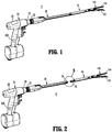
- a surgical instrument 10 including a handle 20, an adaptor 30, and a loading unit 40.
- the adaptor 30 includes a proximal portion having a handle connector 32.
- the handle 20 defines an adaptor receiver 26 for receiving the handle connector 32 to releasably couple the adaptor 30 to the handle 20.
- the loading unit 40 has a proximal portion includes a loading unit connector 42.
- the adaptor 30 has a distal portion that defines a loading unit receiver 36 that is positioned to releasably couple the disposable loading unit 40 to the adaptor 30.
- the loading unit 40 includes an end effector assembly 140 including first and second jaw members 142, 144 that are moveable relative to one another and are configured to act on tissue. It is contemplated that the adapter 30 may be fixed to the handle 20 such that the adapter 30 defines an elongate portion extending from the handle 20.
- the adapter 30 includes a translatable shaft 34 that extends distally through the loading unit receiver 36 and is configured to transfer mechanical energy from the adapter 30 to the loading unit 40 to actuate one or more functions of the end effector assembly 140 ( FIG. 2 ), e.g., approximation and/or firing.
- the loading unit connector 42 of the loading unit 40 defines a shaft receiver 46 that receives the shaft 34 of the adapter 30. When the loading unit connector 42 is fully received within the loading unit receiver 36 the shaft 34 is coupled to the shaft receiver 46 such that translation of the shaft 34 actuates the end effector assembly 140.
- the adapter 30 includes a contactless loading unit detection system 200 to determine the position of the loading unit connector 42 within the loading unit receiver 36.
- the loading unit detection system 200 includes a giant magneto-resistance integrated circuit (GMR IC) 210 embedded within a distal portion of the adapter 30 and the loading unit 40 includes a magnet 48 embedded within the loading unit connector 42.
- GMR IC 210 is configured to output a differential voltage based upon the magnetic field induced in the GMR IC 210 by the magnet 48 of the loading unit 40. It will be appreciated that the differential voltage of the GMR IC 210 increases as a distance between the magnet 48 and the GMR IC 210 decreases.
- the GMR IC 210 may be embedded within or adjacent the loading unit receiver 36 of the adapter 30 and/or the magnet 48 may be embedded within or adjacent the loading unit connector 42.
- the loading unit detection system 200 does not include any exposed contacts. As such, fluid ingress into the loading unit detection system 200 is prevented. By preventing fluid ingress into the loading unit detection system 200, false indemnification of proper coupling of the loading unit 40 with the adapter 30 may be minimized.
- the induced differential voltage of the GMR IC 210 is indicative of the position of the magnet 48 relative to the GMR IC 210 and thus, indicative of the position of the loading unit connector 42 of the loading unit 400 within the loading unit receiver 36 of the adapter 30.
- the differential voltage of the GMR IC 210 reaches a predetermined threshold value, the loading unit connecter 42 is fully received within the loading unit receiver 36 ( FIG. 5 ) such that the loading unit 40 is coupled to the adapter 30.
- the GMR IC 210 may provide an analog or digital output indicative of the position of the loading unit connector 42 within the loading unit receiver 36.
- the handle 20 may include an indicator 28 configured to provide a visual indication of the position of the loading unit 40 within the adapter 30 and/or provide a visual indication when the loading unit 40 is coupled to the adapter 30.
- the differential voltage of the GMR IC 210 may be used to identify the type of loading unit that is coupled to the adapter 30.
- the loading unit 40 may include one or more additional magnets 49 that are/is configured to generate a unique magnetic field in the GMR IC 210 when the loading unit 40 is coupled to the adapter 30 such that the differential voltage of the GMR IC 210 is characteristic of the loading unit 40 that is coupled to the adapter 30.
- the length of the staple line, staple size or sizes, characteristics such as whether the unit has a knife, dissection tip, buttress, etc., can be indicated. An indication that the unit has been used, is unused, or is within or beyond a certain prescribed number of uses, is contemplated.
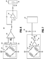
- the differential voltage of the GMR IC 210 is received within a GMR circuit, e.g., GMR circuit 220 ( FIG. 6 ) or GMR circuit 320 ( FIG. 7 ) detailed below, and outputted to a microprocessor 250 ( FIG. 1 ) disposed within the handle 20 of the surgical instrument 10.
- the microprocessor 250 analyzes the output of the GMR circuit to detect and/or identify a loading unit 40 is properly coupled to the adapter 30.
- the GMR circuit 220 includes the GMR IC 210 in the form of a partially shielded bridge 222 with positive and negative outputs 224+, 224-.
- the GMR IC 210 outputs a differential voltage signal based on a magnetic field induced in the GMR IC 210 by the magnets 48, 49 ( FIG. 3 ).
- the differential voltage of the output 224 varies.
- the outputs 224 of the GMR IC 210 are electrically coupled to an instrumentation amplifier 230 which outputs an amplified signal.
- the amplified signal may pass through a filter, e.g., low pass filter 240 before being transmitted to the microprocessor 250.
- the filtered signal of the low pass filter 240 may be transmitted to the analog to digital converter (ADC) 252 of the microprocessor 250 which analyzes the signal to identify the loading unit 40 based on a unique voltage signature and to determine when the loading unit 40 is coupled to the adapter 30.
- the microprocessor 250 may provide visual and/or audible indicia of the type of loading unit 40 and/or when the loading unit 40 is coupled to the adapter 30.
- the visual indicia may be provided on the display 28 ( FIG. 1 ).
- the GMR circuit 320 includes the GMR IC 210 in the form of a partially shielded bridge 322 with positive and negative outputs 324+, 324-.
- the GMR IC 210 outputs a differential voltage signal base on a magnetic field induced in the GMR IC 210 by the magnet 48. Specifically, as the magnetic field experienced by the GMR IC 210 varies, e.g., as the position of the magnet 48 relative to the GMR IC 210 changes, the differential voltage of the output 324 varies.
- the outputs 324 of the GMR IC 210 are electrically coupled to a comparator circuit 330 configured to detect when a signal from the GMR IC 210 exceeds a threshold value indicative of the position of the magnet 48 when the loading unit 40 is coupled to the adapter 30.
- the comparator circuit 330 may include an operational amplifier 332 and a latch 334 such that a connection signal is outputted from the latch 334 to the microprocessor 250 when the voltage of the GMR IC 210 is above the threshold value. It will be appreciated that no connection signal is outputted from the latch 334 when the voltage of the GMR IC 210 is below the threshold value.
- the latch 334 can be reversed such that the connection signal is outputted when the voltage of the GMR IC 210 is below the threshold value and is not outputted when the voltage of the GMR IC 210 is above the threshold value.
- the comparator circuit 330 may be integrated with the shielded bridge 322 to form an integrated GMR IC 210.
- the microprocessor may provide visual and/or audible indicia when the loading unit 40 is coupled to the adapter 30. The visual indicia may be provided on the display 28 ( FIG. 1 ).
- the adapter 30 includes a translating element (not shown) which is translated proximally as the loading unit connector 42 is received within the loading unit receiver 36.
- the magnet 48 and/or magnet 49 may be embedded within the translating element and the GMR IC 210 may be embedded within the adapter 30 at a position to determine the position of the magnet 48.
- the entire detection system 200 may be disposed within the adapter 30 and/or the GMR IC 210 may be positioned in a central or proximal portion of the adapter 30 remote from the loading unit receiver 36.
- the magnet 48 is embedded in the translating element and the magnets 49 are embedded within the loading unit connector 42 to induce a unique voltage in the GMR IC 210.
- handle 20 and the adapter 30 may also include a contactless detection system similar to the contactless detection system 200 detailed above to detect when and/or the type of adapter 30 coupled to the handle 20.
- the microprocessor 250 can be provided in a hand-held housing, a remote console, or some other device.
- the loading unit can be configured to be used in a robotic surgical system.
- the contactless detection system can include technologies other than magnetic, such as induction.
Landscapes
- Health & Medical Sciences (AREA)
- Surgery (AREA)
- Life Sciences & Earth Sciences (AREA)
- Molecular Biology (AREA)
- Animal Behavior & Ethology (AREA)
- Veterinary Medicine (AREA)
- Nuclear Medicine, Radiotherapy & Molecular Imaging (AREA)
- Public Health (AREA)
- Engineering & Computer Science (AREA)
- Biomedical Technology (AREA)
- Heart & Thoracic Surgery (AREA)
- Medical Informatics (AREA)
- General Health & Medical Sciences (AREA)
- Oral & Maxillofacial Surgery (AREA)
- Pathology (AREA)
- Physics & Mathematics (AREA)
- Electromagnetism (AREA)
- Surgical Instruments (AREA)
- Investigating Or Analyzing Materials By The Use Of Magnetic Means (AREA)
Priority Applications (1)
| Application Number | Priority Date | Filing Date | Title |
|---|---|---|---|
| EP22158936.9A EP4023168B1 (de) | 2017-08-23 | 2018-08-22 | Kontaktloser ladevorrichtungsnachweis |
Applications Claiming Priority (2)
| Application Number | Priority Date | Filing Date | Title |
|---|---|---|---|
| US201762549294P | 2017-08-23 | 2017-08-23 | |
| US201716043230A | 2018-07-24 | 2018-07-24 |
Related Child Applications (2)
| Application Number | Title | Priority Date | Filing Date |
|---|---|---|---|
| EP22158936.9A Division EP4023168B1 (de) | 2017-08-23 | 2018-08-22 | Kontaktloser ladevorrichtungsnachweis |
| EP22158936.9A Division-Into EP4023168B1 (de) | 2017-08-23 | 2018-08-22 | Kontaktloser ladevorrichtungsnachweis |
Publications (3)
| Publication Number | Publication Date |
|---|---|
| EP3446641A2 true EP3446641A2 (de) | 2019-02-27 |
| EP3446641A3 EP3446641A3 (de) | 2019-05-08 |
| EP3446641B1 EP3446641B1 (de) | 2022-04-06 |
Family
ID=63452396
Family Applications (2)
| Application Number | Title | Priority Date | Filing Date |
|---|---|---|---|
| EP18190152.1A Active EP3446641B1 (de) | 2017-08-23 | 2018-08-22 | Kontaktloser nachlademagazinnachweis |
| EP22158936.9A Active EP4023168B1 (de) | 2017-08-23 | 2018-08-22 | Kontaktloser ladevorrichtungsnachweis |
Family Applications After (1)
| Application Number | Title | Priority Date | Filing Date |
|---|---|---|---|
| EP22158936.9A Active EP4023168B1 (de) | 2017-08-23 | 2018-08-22 | Kontaktloser ladevorrichtungsnachweis |
Country Status (2)
| Country | Link |
|---|---|
| EP (2) | EP3446641B1 (de) |
| ES (1) | ES2912566T3 (de) |
Citations (2)
| Publication number | Priority date | Publication date | Assignee | Title |
|---|---|---|---|---|
| US20130324979A1 (en) | 2012-06-01 | 2013-12-05 | Covidien Lp | Loading unit detection assembly and surgical device for use therewith |
| US9055943B2 (en) | 2007-09-21 | 2015-06-16 | Covidien Lp | Hand held surgical handle assembly, surgical adapters for use between surgical handle assembly and surgical end effectors, and methods of use |
Family Cites Families (6)
| Publication number | Priority date | Publication date | Assignee | Title |
|---|---|---|---|---|
| US4705038A (en) * | 1985-01-23 | 1987-11-10 | Dyonics, Inc. | Surgical system for powered instruments |
| US9113880B2 (en) * | 2007-10-05 | 2015-08-25 | Covidien Lp | Internal backbone structural chassis for a surgical device |
| US9743929B2 (en) * | 2014-03-26 | 2017-08-29 | Ethicon Llc | Modular powered surgical instrument with detachable shaft assemblies |
| JP6446859B2 (ja) * | 2014-06-27 | 2019-01-09 | ヤマハ株式会社 | 集積回路 |
| US10111679B2 (en) * | 2014-09-05 | 2018-10-30 | Ethicon Llc | Circuitry and sensors for powered medical device |
| US10052044B2 (en) * | 2015-03-06 | 2018-08-21 | Ethicon Llc | Time dependent evaluation of sensor data to determine stability, creep, and viscoelastic elements of measures |
-
2018
- 2018-08-22 EP EP18190152.1A patent/EP3446641B1/de active Active
- 2018-08-22 EP EP22158936.9A patent/EP4023168B1/de active Active
- 2018-08-22 ES ES18190152T patent/ES2912566T3/es active Active
Patent Citations (2)
| Publication number | Priority date | Publication date | Assignee | Title |
|---|---|---|---|---|
| US9055943B2 (en) | 2007-09-21 | 2015-06-16 | Covidien Lp | Hand held surgical handle assembly, surgical adapters for use between surgical handle assembly and surgical end effectors, and methods of use |
| US20130324979A1 (en) | 2012-06-01 | 2013-12-05 | Covidien Lp | Loading unit detection assembly and surgical device for use therewith |
Also Published As
| Publication number | Publication date |
|---|---|
| EP4023168A2 (de) | 2022-07-06 |
| EP3446641B1 (de) | 2022-04-06 |
| EP4023168B1 (de) | 2024-07-31 |
| EP3446641A3 (de) | 2019-05-08 |
| ES2912566T3 (es) | 2022-05-26 |
| EP4023168A3 (de) | 2022-11-02 |
Similar Documents
| Publication | Publication Date | Title |
|---|---|---|
| US20230037993A1 (en) | Surgical instrument and method for detecting the position of a surgical instrument | |
| US12433508B2 (en) | Surgical system having a surgical instrument controlled based on comparison of sensor and database data | |
| US12144518B2 (en) | Surgical systems for detecting end effector tissue distribution irregularities | |
| US20240423615A1 (en) | Surgical instrument cartridge sensor assemblies | |
| US11478324B2 (en) | Contactless loading unit detection | |
| US11596291B2 (en) | Method of compressing tissue within a stapling device and simultaneously displaying of the location of the tissue within the jaws | |
| EP3508140B1 (de) | Klammermagazin mit sensor mit variablen daten | |
| CN107019533B (zh) | 手术接合器组件和手术装载单元的无线检测 | |
| EP2719316B1 (de) | Anschlussstück für einsatz | |
| EP1850783B1 (de) | Sonde zur verwendung in computergestützten operationen | |
| CN106974702B (zh) | 用于远侧目标确定的对齐装置 | |
| EP4079253A1 (de) | Detektionsstifte zur bestimmung der präsenz eines chirurgischen instruments und eines adapters eines manipulators | |
| US10548578B2 (en) | Automatic registration of the penetration depth and the rotational orientation of an invasive instrument | |
| CN112533547B (zh) | 压缩缝合装置内的组织并同时显示组织在钳口内的位置的方法 | |
| CN106470622A (zh) | 手术系统、医疗设备以及手术系统的控制方法 | |
| US9468363B2 (en) | Power supply through a single track of discrete electrodes and method therefor | |
| US20130172696A1 (en) | Medical hand-held measuring device with exchangeable probe | |
| US20250120735A1 (en) | Tissue removal systems and methods | |
| EP4023168B1 (de) | Kontaktloser ladevorrichtungsnachweis | |
| KR101863440B1 (ko) | 환부 위치 파악을 위한 감지 장치 및 방법 | |
| CN110693554A (zh) | 用于互连机电手柄组合件与外科手术装载单元的适配器组合件 | |
| EP2594221B1 (de) | In-situ-Näherungserkennungsvorrichtung | |
| AU2020202936A1 (en) | Load sensing assemblies and methods of manufacturing load sensing assemblies | |
| CN223979825U (zh) | 超声探头导管、超声内窥镜检查组件和活检取样组件 |
Legal Events
| Date | Code | Title | Description |
|---|---|---|---|
| PUAI | Public reference made under article 153(3) epc to a published international application that has entered the european phase |
Free format text: ORIGINAL CODE: 0009012 |
|
| STAA | Information on the status of an ep patent application or granted ep patent |
Free format text: STATUS: THE APPLICATION HAS BEEN PUBLISHED |
|
| AK | Designated contracting states |
Kind code of ref document: A2 Designated state(s): AL AT BE BG CH CY CZ DE DK EE ES FI FR GB GR HR HU IE IS IT LI LT LU LV MC MK MT NL NO PL PT RO RS SE SI SK SM TR |
|
| AX | Request for extension of the european patent |
Extension state: BA ME |
|
| PUAL | Search report despatched |
Free format text: ORIGINAL CODE: 0009013 |
|
| AK | Designated contracting states |
Kind code of ref document: A3 Designated state(s): AL AT BE BG CH CY CZ DE DK EE ES FI FR GB GR HR HU IE IS IT LI LT LU LV MC MK MT NL NO PL PT RO RS SE SI SK SM TR |
|
| AX | Request for extension of the european patent |
Extension state: BA ME |
|
| RIC1 | Information provided on ipc code assigned before grant |
Ipc: A61B 90/00 20160101ALI20190403BHEP Ipc: A61B 17/00 20060101ALI20190403BHEP Ipc: A61B 17/072 20060101AFI20190403BHEP |
|
| STAA | Information on the status of an ep patent application or granted ep patent |
Free format text: STATUS: REQUEST FOR EXAMINATION WAS MADE |
|
| 17P | Request for examination filed |
Effective date: 20191106 |
|
| RBV | Designated contracting states (corrected) |
Designated state(s): AL AT BE BG CH CY CZ DE DK EE ES FI FR GB GR HR HU IE IS IT LI LT LU LV MC MK MT NL NO PL PT RO RS SE SI SK SM TR |
|
| STAA | Information on the status of an ep patent application or granted ep patent |
Free format text: STATUS: EXAMINATION IS IN PROGRESS |
|
| 17Q | First examination report despatched |
Effective date: 20200512 |
|
| GRAP | Despatch of communication of intention to grant a patent |
Free format text: ORIGINAL CODE: EPIDOSNIGR1 |
|
| STAA | Information on the status of an ep patent application or granted ep patent |
Free format text: STATUS: GRANT OF PATENT IS INTENDED |
|
| INTG | Intention to grant announced |
Effective date: 20211020 |
|
| RIN1 | Information on inventor provided before grant (corrected) |
Inventor name: CALDERONI, ANTHONY Inventor name: PANTAZIS, JOHN |
|
| GRAS | Grant fee paid |
Free format text: ORIGINAL CODE: EPIDOSNIGR3 |
|
| GRAA | (expected) grant |
Free format text: ORIGINAL CODE: 0009210 |
|
| STAA | Information on the status of an ep patent application or granted ep patent |
Free format text: STATUS: THE PATENT HAS BEEN GRANTED |
|
| AK | Designated contracting states |
Kind code of ref document: B1 Designated state(s): AL AT BE BG CH CY CZ DE DK EE ES FI FR GB GR HR HU IE IS IT LI LT LU LV MC MK MT NL NO PL PT RO RS SE SI SK SM TR |
|
| REG | Reference to a national code |
Ref country code: GB Ref legal event code: FG4D |
|
| REG | Reference to a national code |
Ref country code: CH Ref legal event code: EP |
|
| REG | Reference to a national code |
Ref country code: AT Ref legal event code: REF Ref document number: 1480557 Country of ref document: AT Kind code of ref document: T Effective date: 20220415 |
|
| REG | Reference to a national code |
Ref country code: DE Ref legal event code: R096 Ref document number: 602018033251 Country of ref document: DE |
|
| REG | Reference to a national code |
Ref country code: IE Ref legal event code: FG4D |
|
| REG | Reference to a national code |
Ref country code: ES Ref legal event code: FG2A Ref document number: 2912566 Country of ref document: ES Kind code of ref document: T3 Effective date: 20220526 |
|
| REG | Reference to a national code |
Ref country code: LT Ref legal event code: MG9D |
|
| REG | Reference to a national code |
Ref country code: NL Ref legal event code: MP Effective date: 20220406 |
|
| REG | Reference to a national code |
Ref country code: AT Ref legal event code: MK05 Ref document number: 1480557 Country of ref document: AT Kind code of ref document: T Effective date: 20220406 |
|
| PG25 | Lapsed in a contracting state [announced via postgrant information from national office to epo] |
Ref country code: NL Free format text: LAPSE BECAUSE OF FAILURE TO SUBMIT A TRANSLATION OF THE DESCRIPTION OR TO PAY THE FEE WITHIN THE PRESCRIBED TIME-LIMIT Effective date: 20220406 |
|
| PG25 | Lapsed in a contracting state [announced via postgrant information from national office to epo] |
Ref country code: SE Free format text: LAPSE BECAUSE OF FAILURE TO SUBMIT A TRANSLATION OF THE DESCRIPTION OR TO PAY THE FEE WITHIN THE PRESCRIBED TIME-LIMIT Effective date: 20220406 Ref country code: PT Free format text: LAPSE BECAUSE OF FAILURE TO SUBMIT A TRANSLATION OF THE DESCRIPTION OR TO PAY THE FEE WITHIN THE PRESCRIBED TIME-LIMIT Effective date: 20220808 Ref country code: NO Free format text: LAPSE BECAUSE OF FAILURE TO SUBMIT A TRANSLATION OF THE DESCRIPTION OR TO PAY THE FEE WITHIN THE PRESCRIBED TIME-LIMIT Effective date: 20220706 Ref country code: LT Free format text: LAPSE BECAUSE OF FAILURE TO SUBMIT A TRANSLATION OF THE DESCRIPTION OR TO PAY THE FEE WITHIN THE PRESCRIBED TIME-LIMIT Effective date: 20220406 Ref country code: HR Free format text: LAPSE BECAUSE OF FAILURE TO SUBMIT A TRANSLATION OF THE DESCRIPTION OR TO PAY THE FEE WITHIN THE PRESCRIBED TIME-LIMIT Effective date: 20220406 Ref country code: GR Free format text: LAPSE BECAUSE OF FAILURE TO SUBMIT A TRANSLATION OF THE DESCRIPTION OR TO PAY THE FEE WITHIN THE PRESCRIBED TIME-LIMIT Effective date: 20220707 Ref country code: FI Free format text: LAPSE BECAUSE OF FAILURE TO SUBMIT A TRANSLATION OF THE DESCRIPTION OR TO PAY THE FEE WITHIN THE PRESCRIBED TIME-LIMIT Effective date: 20220406 Ref country code: BG Free format text: LAPSE BECAUSE OF FAILURE TO SUBMIT A TRANSLATION OF THE DESCRIPTION OR TO PAY THE FEE WITHIN THE PRESCRIBED TIME-LIMIT Effective date: 20220706 Ref country code: AT Free format text: LAPSE BECAUSE OF FAILURE TO SUBMIT A TRANSLATION OF THE DESCRIPTION OR TO PAY THE FEE WITHIN THE PRESCRIBED TIME-LIMIT Effective date: 20220406 |
|
| PGFP | Annual fee paid to national office [announced via postgrant information from national office to epo] |
Ref country code: IE Payment date: 20220721 Year of fee payment: 5 Ref country code: ES Payment date: 20220901 Year of fee payment: 5 |
|
| PG25 | Lapsed in a contracting state [announced via postgrant information from national office to epo] |
Ref country code: RS Free format text: LAPSE BECAUSE OF FAILURE TO SUBMIT A TRANSLATION OF THE DESCRIPTION OR TO PAY THE FEE WITHIN THE PRESCRIBED TIME-LIMIT Effective date: 20220406 Ref country code: PL Free format text: LAPSE BECAUSE OF FAILURE TO SUBMIT A TRANSLATION OF THE DESCRIPTION OR TO PAY THE FEE WITHIN THE PRESCRIBED TIME-LIMIT Effective date: 20220406 Ref country code: LV Free format text: LAPSE BECAUSE OF FAILURE TO SUBMIT A TRANSLATION OF THE DESCRIPTION OR TO PAY THE FEE WITHIN THE PRESCRIBED TIME-LIMIT Effective date: 20220406 Ref country code: IS Free format text: LAPSE BECAUSE OF FAILURE TO SUBMIT A TRANSLATION OF THE DESCRIPTION OR TO PAY THE FEE WITHIN THE PRESCRIBED TIME-LIMIT Effective date: 20220806 |
|
| REG | Reference to a national code |
Ref country code: DE Ref legal event code: R097 Ref document number: 602018033251 Country of ref document: DE |
|
| PG25 | Lapsed in a contracting state [announced via postgrant information from national office to epo] |
Ref country code: SM Free format text: LAPSE BECAUSE OF FAILURE TO SUBMIT A TRANSLATION OF THE DESCRIPTION OR TO PAY THE FEE WITHIN THE PRESCRIBED TIME-LIMIT Effective date: 20220406 Ref country code: SK Free format text: LAPSE BECAUSE OF FAILURE TO SUBMIT A TRANSLATION OF THE DESCRIPTION OR TO PAY THE FEE WITHIN THE PRESCRIBED TIME-LIMIT Effective date: 20220406 Ref country code: RO Free format text: LAPSE BECAUSE OF FAILURE TO SUBMIT A TRANSLATION OF THE DESCRIPTION OR TO PAY THE FEE WITHIN THE PRESCRIBED TIME-LIMIT Effective date: 20220406 Ref country code: EE Free format text: LAPSE BECAUSE OF FAILURE TO SUBMIT A TRANSLATION OF THE DESCRIPTION OR TO PAY THE FEE WITHIN THE PRESCRIBED TIME-LIMIT Effective date: 20220406 Ref country code: DK Free format text: LAPSE BECAUSE OF FAILURE TO SUBMIT A TRANSLATION OF THE DESCRIPTION OR TO PAY THE FEE WITHIN THE PRESCRIBED TIME-LIMIT Effective date: 20220406 Ref country code: CZ Free format text: LAPSE BECAUSE OF FAILURE TO SUBMIT A TRANSLATION OF THE DESCRIPTION OR TO PAY THE FEE WITHIN THE PRESCRIBED TIME-LIMIT Effective date: 20220406 |
|
| PLBE | No opposition filed within time limit |
Free format text: ORIGINAL CODE: 0009261 |
|
| STAA | Information on the status of an ep patent application or granted ep patent |
Free format text: STATUS: NO OPPOSITION FILED WITHIN TIME LIMIT |
|
| 26N | No opposition filed |
Effective date: 20230110 |
|
| PG25 | Lapsed in a contracting state [announced via postgrant information from national office to epo] |
Ref country code: MC Free format text: LAPSE BECAUSE OF FAILURE TO SUBMIT A TRANSLATION OF THE DESCRIPTION OR TO PAY THE FEE WITHIN THE PRESCRIBED TIME-LIMIT Effective date: 20220406 Ref country code: AL Free format text: LAPSE BECAUSE OF FAILURE TO SUBMIT A TRANSLATION OF THE DESCRIPTION OR TO PAY THE FEE WITHIN THE PRESCRIBED TIME-LIMIT Effective date: 20220406 |
|
| REG | Reference to a national code |
Ref country code: CH Ref legal event code: PL |
|
| GBPC | Gb: european patent ceased through non-payment of renewal fee |
Effective date: 20220822 |
|
| PG25 | Lapsed in a contracting state [announced via postgrant information from national office to epo] |
Ref country code: LU Free format text: LAPSE BECAUSE OF NON-PAYMENT OF DUE FEES Effective date: 20220822 Ref country code: LI Free format text: LAPSE BECAUSE OF NON-PAYMENT OF DUE FEES Effective date: 20220831 Ref country code: CH Free format text: LAPSE BECAUSE OF NON-PAYMENT OF DUE FEES Effective date: 20220831 |
|
| REG | Reference to a national code |
Ref country code: BE Ref legal event code: MM Effective date: 20220831 |
|
| PG25 | Lapsed in a contracting state [announced via postgrant information from national office to epo] |
Ref country code: SI Free format text: LAPSE BECAUSE OF FAILURE TO SUBMIT A TRANSLATION OF THE DESCRIPTION OR TO PAY THE FEE WITHIN THE PRESCRIBED TIME-LIMIT Effective date: 20220406 |
|
| PG25 | Lapsed in a contracting state [announced via postgrant information from national office to epo] |
Ref country code: BE Free format text: LAPSE BECAUSE OF NON-PAYMENT OF DUE FEES Effective date: 20220831 |
|
| PG25 | Lapsed in a contracting state [announced via postgrant information from national office to epo] |
Ref country code: GB Free format text: LAPSE BECAUSE OF NON-PAYMENT OF DUE FEES Effective date: 20220822 |
|
| PG25 | Lapsed in a contracting state [announced via postgrant information from national office to epo] |
Ref country code: IT Free format text: LAPSE BECAUSE OF FAILURE TO SUBMIT A TRANSLATION OF THE DESCRIPTION OR TO PAY THE FEE WITHIN THE PRESCRIBED TIME-LIMIT Effective date: 20220406 |
|
| PG25 | Lapsed in a contracting state [announced via postgrant information from national office to epo] |
Ref country code: HU Free format text: LAPSE BECAUSE OF FAILURE TO SUBMIT A TRANSLATION OF THE DESCRIPTION OR TO PAY THE FEE WITHIN THE PRESCRIBED TIME-LIMIT; INVALID AB INITIO Effective date: 20180822 |
|
| PG25 | Lapsed in a contracting state [announced via postgrant information from national office to epo] |
Ref country code: CY Free format text: LAPSE BECAUSE OF FAILURE TO SUBMIT A TRANSLATION OF THE DESCRIPTION OR TO PAY THE FEE WITHIN THE PRESCRIBED TIME-LIMIT Effective date: 20220406 |
|
| REG | Reference to a national code |
Ref country code: IE Ref legal event code: MM4A |
|
| PG25 | Lapsed in a contracting state [announced via postgrant information from national office to epo] |
Ref country code: MK Free format text: LAPSE BECAUSE OF FAILURE TO SUBMIT A TRANSLATION OF THE DESCRIPTION OR TO PAY THE FEE WITHIN THE PRESCRIBED TIME-LIMIT Effective date: 20220406 |
|
| PG25 | Lapsed in a contracting state [announced via postgrant information from national office to epo] |
Ref country code: TR Free format text: LAPSE BECAUSE OF FAILURE TO SUBMIT A TRANSLATION OF THE DESCRIPTION OR TO PAY THE FEE WITHIN THE PRESCRIBED TIME-LIMIT Effective date: 20220406 |
|
| PG25 | Lapsed in a contracting state [announced via postgrant information from national office to epo] |
Ref country code: IE Free format text: LAPSE BECAUSE OF NON-PAYMENT OF DUE FEES Effective date: 20230822 |
|
| PG25 | Lapsed in a contracting state [announced via postgrant information from national office to epo] |
Ref country code: IE Free format text: LAPSE BECAUSE OF NON-PAYMENT OF DUE FEES Effective date: 20230822 |
|
| REG | Reference to a national code |
Ref country code: ES Ref legal event code: FD2A Effective date: 20240927 |
|
| PG25 | Lapsed in a contracting state [announced via postgrant information from national office to epo] |
Ref country code: MT Free format text: LAPSE BECAUSE OF FAILURE TO SUBMIT A TRANSLATION OF THE DESCRIPTION OR TO PAY THE FEE WITHIN THE PRESCRIBED TIME-LIMIT Effective date: 20220406 |
|
| PG25 | Lapsed in a contracting state [announced via postgrant information from national office to epo] |
Ref country code: ES Free format text: LAPSE BECAUSE OF NON-PAYMENT OF DUE FEES Effective date: 20230823 |
|
| PG25 | Lapsed in a contracting state [announced via postgrant information from national office to epo] |
Ref country code: ES Free format text: LAPSE BECAUSE OF NON-PAYMENT OF DUE FEES Effective date: 20230823 |
|
| PG25 | Lapsed in a contracting state [announced via postgrant information from national office to epo] |
Ref country code: BG Free format text: LAPSE BECAUSE OF FAILURE TO SUBMIT A TRANSLATION OF THE DESCRIPTION OR TO PAY THE FEE WITHIN THE PRESCRIBED TIME-LIMIT Effective date: 20220406 |
|
| PG25 | Lapsed in a contracting state [announced via postgrant information from national office to epo] |
Ref country code: BG Free format text: LAPSE BECAUSE OF FAILURE TO SUBMIT A TRANSLATION OF THE DESCRIPTION OR TO PAY THE FEE WITHIN THE PRESCRIBED TIME-LIMIT Effective date: 20220406 |
|
| PGFP | Annual fee paid to national office [announced via postgrant information from national office to epo] |
Ref country code: DE Payment date: 20250724 Year of fee payment: 8 |
|
| PGFP | Annual fee paid to national office [announced via postgrant information from national office to epo] |
Ref country code: FR Payment date: 20250725 Year of fee payment: 8 |