EP3445897B1 - Electrospinning device and method - Google Patents
Electrospinning device and method Download PDFInfo
- Publication number
- EP3445897B1 EP3445897B1 EP17717752.4A EP17717752A EP3445897B1 EP 3445897 B1 EP3445897 B1 EP 3445897B1 EP 17717752 A EP17717752 A EP 17717752A EP 3445897 B1 EP3445897 B1 EP 3445897B1
- Authority
- EP
- European Patent Office
- Prior art keywords
- collector
- fibrous structure
- measurement system
- optical measurement
- distance
- Prior art date
- Legal status (The legal status is an assumption and is not a legal conclusion. Google has not performed a legal analysis and makes no representation as to the accuracy of the status listed.)
- Active
Links
Images


Classifications
-
- D—TEXTILES; PAPER
- D01—NATURAL OR MAN-MADE THREADS OR FIBRES; SPINNING
- D01D—MECHANICAL METHODS OR APPARATUS IN THE MANUFACTURE OF ARTIFICIAL FILAMENTS, THREADS, FIBRES, BRISTLES OR RIBBONS
- D01D5/00—Formation of filaments, threads, or the like
- D01D5/0007—Electro-spinning
- D01D5/0061—Electro-spinning characterised by the electro-spinning apparatus
-
- B—PERFORMING OPERATIONS; TRANSPORTING
- B29—WORKING OF PLASTICS; WORKING OF SUBSTANCES IN A PLASTIC STATE IN GENERAL
- B29C—SHAPING OR JOINING OF PLASTICS; SHAPING OF MATERIAL IN A PLASTIC STATE, NOT OTHERWISE PROVIDED FOR; AFTER-TREATMENT OF THE SHAPED PRODUCTS, e.g. REPAIRING
- B29C41/00—Shaping by coating a mould, core or other substrate, i.e. by depositing material and stripping-off the shaped article; Apparatus therefor
- B29C41/006—Shaping by coating a mould, core or other substrate, i.e. by depositing material and stripping-off the shaped article; Apparatus therefor using an electrostatic field for applying the material
-
- D—TEXTILES; PAPER
- D01—NATURAL OR MAN-MADE THREADS OR FIBRES; SPINNING
- D01D—MECHANICAL METHODS OR APPARATUS IN THE MANUFACTURE OF ARTIFICIAL FILAMENTS, THREADS, FIBRES, BRISTLES OR RIBBONS
- D01D13/00—Complete machines for producing artificial threads
-
- D—TEXTILES; PAPER
- D01—NATURAL OR MAN-MADE THREADS OR FIBRES; SPINNING
- D01D—MECHANICAL METHODS OR APPARATUS IN THE MANUFACTURE OF ARTIFICIAL FILAMENTS, THREADS, FIBRES, BRISTLES OR RIBBONS
- D01D13/00—Complete machines for producing artificial threads
- D01D13/02—Elements of machines in combination
-
- D—TEXTILES; PAPER
- D01—NATURAL OR MAN-MADE THREADS OR FIBRES; SPINNING
- D01D—MECHANICAL METHODS OR APPARATUS IN THE MANUFACTURE OF ARTIFICIAL FILAMENTS, THREADS, FIBRES, BRISTLES OR RIBBONS
- D01D5/00—Formation of filaments, threads, or the like
- D01D5/0007—Electro-spinning
-
- D—TEXTILES; PAPER
- D01—NATURAL OR MAN-MADE THREADS OR FIBRES; SPINNING
- D01D—MECHANICAL METHODS OR APPARATUS IN THE MANUFACTURE OF ARTIFICIAL FILAMENTS, THREADS, FIBRES, BRISTLES OR RIBBONS
- D01D5/00—Formation of filaments, threads, or the like
- D01D5/0007—Electro-spinning
- D01D5/0061—Electro-spinning characterised by the electro-spinning apparatus
- D01D5/0076—Electro-spinning characterised by the electro-spinning apparatus characterised by the collecting device, e.g. drum, wheel, endless belt, plate or grid
-
- D—TEXTILES; PAPER
- D04—BRAIDING; LACE-MAKING; KNITTING; TRIMMINGS; NON-WOVEN FABRICS
- D04H—MAKING TEXTILE FABRICS, e.g. FROM FIBRES OR FILAMENTARY MATERIAL; FABRICS MADE BY SUCH PROCESSES OR APPARATUS, e.g. FELTS, NON-WOVEN FABRICS; COTTON-WOOL; WADDING ; NON-WOVEN FABRICS FROM STAPLE FIBRES, FILAMENTS OR YARNS, BONDED WITH AT LEAST ONE WEB-LIKE MATERIAL DURING THEIR CONSOLIDATION
- D04H1/00—Non-woven fabrics formed wholly or mainly of staple fibres or like relatively short fibres
- D04H1/70—Non-woven fabrics formed wholly or mainly of staple fibres or like relatively short fibres characterised by the method of forming fleeces or layers, e.g. reorientation of fibres
- D04H1/72—Non-woven fabrics formed wholly or mainly of staple fibres or like relatively short fibres characterised by the method of forming fleeces or layers, e.g. reorientation of fibres the fibres being randomly arranged
- D04H1/728—Non-woven fabrics formed wholly or mainly of staple fibres or like relatively short fibres characterised by the method of forming fleeces or layers, e.g. reorientation of fibres the fibres being randomly arranged by electro-spinning
Definitions
- the invention relates to an electrospinning device and a method of producing a fibrous structure using such a device.
- the invention also relates to a measuring device for measuring a thickness of a fibrous structure and to a method of measuring a thickness of a fibrous structure.
- Electrospinning is a method to produce continuous fibers with a diameter ranging from a few tens of nanometres to a few tens of micrometres.
- a suitable liquefied material may be fed through a small, electrically conductive nozzle.
- the liquefied material may be electrically charged by applying a high voltage between the nozzle and a counter electrode.
- the generated electric field causes a cone-shape deformation of the droplet at the nozzle tip. Once the surface tension of this droplet is overcome by the electrical force, a jet is formed out of the droplet and a fiber forms that moves towards the counter electrode.
- the fiber is continuously stretched and elongated by the different forces acting on it, reducing its diameter and allowing it to solidify (by evaporation of the solvent or cooling of the material) such that a solid fiber is deposited on the collector (which is placed just before the counter electrode or the counter electrode is used as collector directly).
- a structure of fibrous layers is formed on the counter electrode or collector. Due to the extremely small fiber diameter and the porous nature of this structure, it is difficult to accurately measure the thickness of the resulting fibrous structure because the structure's surface consists of very thin fibers and is hence compressible. Furthermore, the structure's surface is not smooth but consists of a (random or oriented) mesh of fibers and pores.
- Thickness measurement methods that require direct contact with the structure will yield inaccurate results since the mechanical contact of the measuring device will compress the fibrous structure.
- Other measuring methods like SEM and light microscopy are destructive since they require slicing of the fibrous structure to allow the measurement system to "look" at the cross-section of the structure.
- the present invention provides an electrospinning device that enables in-situ measuring of a thickness of the produced fibrous structure according to claims 1-15.
- a first aspect of the invention provides an electrospinning device comprising:
- a momentary thickness can be calculated at one location or at a plurality of locations. These locations could be predefined by a user or operator by providing one or more coordinates.
- the device is measuring the thickness of the electro spun fibrous structure being produced. This will give an improved control over the production process, as compared to known thickness measurements in which measurements are done after the spinning process. Furthermore, the fibrous structure does not need to be touched or cut into pieces.
- the thickness can be measured very accurately by measuring the distance from the collector to the optical measurement system and the distance from the (momentary) top layer to the optical measurement system at the at least one location. By also measuring the distance from the collector to the optical measurement system, a kind of initial height map or baseline can be made, so that fluctuations in the collector surface are corrected for. In case the collector is a rotatable collector, the fluctuations due to of axis orientation of the collector can also be compensated for.
- the collector is movably arranged relative to the nozzle.
- relatively large collectors can be used that may be covered with electro spun material over a wide area resulting in large fibrous structures.
- moving the nozzle relative to the collector both even and uneven distribution of fibers and thus structure thickness on the collector are possible.
- the optical measurement system is movably arranged relative to the surface of the collector. In this way, one measurement system can be used to measure at several locations on the collector.
- the optical measurement system is statically arranged relative to a surface of the collector so as to measure at a single location. In this embodiment, no moving device element are needed and the measurement system will be able to very accurately measure a distance in situ.
- several measurement systems may be used, such as several triangulation sensors, arranged at different predefined locations relative to the collector.
- the processor is arranged to control at least one out of the following:
- the feedback of the momentary thickness is used to control or adjust the voltage difference and/or the material feed and/or the nozzle position relative to the collector.
- This online feedback of the measured thickness results in a controlled production of the structure and enables a continuation of the spinning process towards a predefined target structure thickness.
- a reduction of waste of electrospinning material may be achieved as compared to known devices.
- the processor is arranged to control the voltage supply system so as to stop the electrospinning process once a required thickness of the fibrous structure has been reached. This provides for the ability to continue the spinning process towards a predefined structure thickness. Also an additional reduction of waste of electrospinning material may be achieved.
- the processor is arranged to control a movement of the collector relative to the nozzle so as to produce different thickness of the fibrous structure at different locations. In this way, more complex fiber structures can be created that have different thickness at different locations.
- the collector is rotatable around a rotation axis.
- the collector may be cylindrical or have a more complex freeform shape. When using such rotating shapes, a multiple number of structures are conceivable.
- a relatively simple structure may be a tubular structure that could be used as a stent in the medical field.
- the tubular structure may also be cut and flattened after the spinning process to create a substantially flat layer of electro spun material.
- the optical measurement system comprises a laser device and an optical sensor, wherein the laser device is arranged to send a light beam towards the collector and the sensor is arranged to measure reflected radiation coming from the collector and/or the fibrous structure.
- optical measurement makes contactless measurement possible and no damage to the fibrous structure will occur.
- the optical system may comprise a laser and an optical sensor that can be placed at a certain distance away from the collector to avoid interference of the measurement system during the electrospinning process.
- the optical sensor is a 1D or 2D sensor array arranged to detect radiation along at least one axis
- the processor is arranged to translate radiation intensities along the axis of the sensor into a reflection curve and to detect a first peak in the reflection curve, wherein the first peak is used by the processor to determine the distance between either the collector or the momentary top layer of the fibrous structure and the optical measurement system.
- the optical measurement system comprises a laser triangulation sensor.
- a laser triangulation sensor is both contactless, accurate and cost-effective.
- a relatively long distance between the optical measurement system and the collector can be used so that interference of the measurement device with can be avoided.
- the laser device is arranged to produce a laser beam having a cross section between 25 ⁇ m and 5000 ⁇ m, preferably between 70 and 2500 ⁇ m.
- the spot produced by the laser may be circular-, oval- or line shaped.
- the preferred cross section of the laser beam is large enough to cover a number of fibers and pores at the momentary top layer of the electro spun fibrous structure to yield sufficient reflection (detectable amount of radiation intensity) from the momentary top layer of the electro spun fibrous structure, although small enough to be able to distinguish between small height (distance) differences in a region of interest on the momentary top layer of the electro spun fibrous structure.
- the device comprises a user interface wherein the processor is arranged to receive predefined coordinates from a user via the user interface.
- the user may freely select one or more coordinates at which the thickness of the fibrous structure is calculated. Selection of the coordinates may be done by the user or operator interacting with control software loaded on the processor prior to the measurement.
- the electrospinning device further comprises a position measurement system arranged to measure a position of the collector relative to the optical measurement system.
- the processor may then be arranged to receive position information from the position measurement system and to trigger the optical measurement system in dependency on the received position information.
- a user may define some measurement locations on the collector at which a measurement is desired. These locations may be programmed in a so-called trigger controller incorporated in the processor that triggers the acquisition of a measurement point with the optical measurement system on the selected measurement positions. In this way it is possible to measure repeatedly and accurately at exactly the predefined coordinates.
- a measuring device for measuring a thickness of a fibrous structure comprising:
- the measuring device can be used to calculate a thickness of an electro spun fibrous structure produced in an electrospinning device.
- the electro spun fibrous structure can be transported from the electrospinning device to the measurement device by detaching the collector from the electrospinning device, and by attaching (i.e. mounting) the collector (with the fibrous structure on it) to the measurement device. In this way, the fibrous structure does not need to be removed from the collector and thus not need to be touched, thereby avoiding damages to the fibrous structure.
- the measuring device further comprises a position measurement system arranged to measure a position of the carrier relative to the optical measurement system, wherein the processor is arranged to receive position information from the position measurement system and to trigger the optical measurement system in dependency on the received position information.
- the position-based triggering of the optical measurement system enables an accurate repetition of the measurements at the predefined coordinates (e.g. to measure baseline and top layer distance at exactly the same coordinate so the difference calculation is representative for the thickness of the fibrous structure at that coordinate).
- the measuring device comprises a mounting system to install the carrier with a fixed orientation relative to the frame.
- the carrier is movable relative to the optical measurement system in at least one dimension. This enables the measuring of the thickness for multiple coordinates.
- the carrier is substantially cylindrical and rotatable relative to the optical measurement system. This enables the measuring of tubular structures or other freeform or 3D structures.
- a method of producing a fibrous structure comprising:
- a method of measuring a thickness of a fibrous structure comprising:
- This method may be applied to check the quality of electro spun fibrous structures by comparing the actual thickness with a desired or required value.
- An advantage of this method is that it allows for using special measurement devices that comprise measuring configurations not possible in the electrospinning devices that may have insufficient space for a measurement device.
- Figure 1 schematically shows a side view of a first embodiment of the electrospinning device 100.
- the device 100 comprises a container 50 for holding a liquid comprising a polymer melt or a polymer solution, and a nozzle 51 arranged to outlet a stream of the liquid from the container 50.
- the container 50 can be arranged remote from the nozzle 51 wherein it is in fluidic connection with the nozzle 51 by means of for example a tube.
- the device 100 further comprises a collector 1 for collecting electro spun material coming from the nozzle 51 during an electrospinning process.
- a voltage supply system 14 is arranged to create a voltage difference between the nozzle 51 and the collector 1.
- the voltage supply system 14 may comprise one AC or DC voltage supply to create the voltage difference or it may comprise two voltage supplies, one creating a voltage difference between the collector 1 and ground and one creating a difference between the nozzle 51 and ground. Due to the applied voltage(s), an electro spun fiber 52 is created that flies from the nozzle 51 to the collector 1 on which it is collected to form an electro spun fibrous structure 53.
- the electrospinning device 100 also comprises an optical measurement system (OMS) 108 (reference example only) arranged to measure a distance between the collector 1 or the electro spun fibrous structure 53 and a reference point 13 of the OMS 108.
- OMS optical measurement system
- the OMS 108 comprises a laser 8 and an optical sensor 12.
- the reference point 13 is situated at the front of the optical sensor 12. It is noted that the reference point 13 can be located at other locations, as will be clear to the skilled person.
- the reference point 13 can be used in the processing of the measured signals in order to calculate an absolute distance if needed.
- the laser 8 is arranged to create a laser beam 9 which is directed to the collector 1 and depending on the situation, hits the empty collector 1 or the electro spun fibrous structure 53 at a measurement position 54.
- the measurement position 54 can correspond to a predefined coordinate at which a distance measurement is to be taken.
- the laser beam 8 is reflected by the collector and/or by the electro spun fibrous structure 53 on the collector 1 and is detected by the optical
- the electrospinning device 100 also comprises a processor 111.
- the processor 111 is arranged to receive the measured distances for at least one location on the collector 1 from the OMS 108 before the electrospinning process and also during the electrospinning process.
- the processor 111 is arranged to calculate a momentary thickness during the electrospinning process of the fibrous structure for the at least one location using the received distances.
- the electrospinning device 100 may comprise a metrology frame 107 arranged to support the collector 1 and the OMS 108.
- the OMS 108 can be moved and positioned relative to the metrology frame 107 by means of OMS positioning module 109 indicated in Figure 1 by way of arrows 109.
- the arrows 109 indicate that the movement of the OMS 108 relative to the metrology frame 107 is possible in up to six degrees of freedom (DOF).
- DOF degrees of freedom
- the nozzle 51 can be positioned relative to the OMS 108, i.e. relative to the sensor 12. So, this positioning is also possible in up to 6 DOF.
- the above mentioned relative positioning of the OMS 108 and of the nozzle 51 are optional and that the different elements shown in Figure 1 could all be fixed to the frame 107.
- the nozzle 51 is able to move relative to the collector 1. This may be done using the above mentioned positioning means or a different separate system (not shown) arranged to move the collector relative to the frame 107.
- the collector 1 in Figure 1 may have a top surface with different shapes such as rectangular, square shaped, disc shaped or any other suitable form depending on the structure to be produced. The top surface could be flat or curved.
- the collector could also have indentations or recesses, and/or it may have extensions so as to create different fibrous structures.
- the collector is mounted onto the frame 107 by means of a mounting system comprising a mount top element 201 and a mount bottom element 202.
- the mounting system is arranged to removably position the collector 1 relative to the frame 107.
- the mounting system is a kinematic coupling system.
- FIG 2 shows a perspective view of the mounting system used in Figure 1 according to an embodiment.
- the mounting system is a kinematic coupling system comprising a top element 201 and a bottom element 202.
- the top element 201 comprises three semi-spherical elements 203 while the bottom element 202 comprises three grooves 204.
- the bottom element 202 comprises an orientation pin 205, while the top element 201 comprises a clearance hole 206 cooperating with the orientation pin 206.
- the top element 201 comprises threaded hole 207 for receiving an outer end of a drawbar 208, the draw bar 208 being biased by means of a spring 209.
- the top element 201 can only be positioned and connected in one way on top of the bottom element 202.
- the mounting system 201,202 is optional, however its presence will enable the user to remove the collector 1 from the electrospinning device and place it into another device for measuring purposes or other operations on the fibrous structure in which accurate alignment is preferred.
- FIG 3 schematically shows a further embodiment of the electrospinning device 100.
- the electrospinning device 100 comprises a substantially cylindrical collector 1 which is rotatable relative to the nozzle 51 (reference example only). In this way, a cylindrical fibrous structure can be created during an electrospinning process. Since the collector 1 is rotatable, it is also referred to as the rotating mandrel 1.
- the nozzle 51 is also referred to as the spinneret 51 which may be charged with a high voltage for fiber fabrication similar to the process described with reference to Figure 1 .
- an electrospun fiber 52 is ejected as a droplet at (a tip of) the nozzle 51 and it flies from the nozzle 51 to the collector 1 while it stretches and solidifies in an electrostatic field between the charged nozzle 51 and the charged collector 1.
- electrospun fibers are collected that form a porous fibrous layer 53 on the collector 1, also referred to as electro spun fibrous structure 53.
- the electrospinning device 100 also comprises a drive shaft 101 connecting the collector 1 to actuator components 102-106.
- the actuator components in this example comprise amongst others two bearings 102a, 102b of which bearing 102b is optional.
- the bearings 102a, 102b are arranged to support the drive shaft 101 that holds the rotating collector 1.
- Each bearing is arranged on one end of the collector 1.
- the electrospinning device 100 also comprises a HV (high voltage) contact unit 103 arranged to provide a high-voltage or a grounded connection to the rotating collector 1.
- An HV isolating transmission 104 is arranged to decouple the HV-charged collector 1 from a motor 105 so as to protect the motor 105.
- the motor 105 may be a DC, AC, a stepper, or a servomotor.
- the device 100 comprises a first connecting interface 114a and a second connection interface 114b.
- the first connecting interface 114a and the second connection interface 114b are also referred to as the mounting system 114.
- the mounting system is arranged to removably mount the collector 1 into the device 100.
- the mounting system 114 is preferably arranged to fix the collector 1 onto the shaft 101 in 6 DOF. So for example, the first connecting interface 114a may cause the collector 1 to be fixed in 4 DOF while the second connection interface 114b is arranged to fix the collector in 2 DOF.
- the bearing 102b is optional and in that situation the second connecting interface 114b is absent; in that case the first connection interface may be arranged to fixate the collector 1 relative to the shaft 101 in 6 DOF.
- the electrospinning device 100 also comprises a processor 111.
- the processor 111 may be arranged to send a motor setpoint signal 105a to the motor 105.
- the setpoint signal 105a may comprise position and/or velocity information.
- the actuator components further comprise a rotational position sensor 106, which may be a rotational encoder (absolute or incremental).
- the rotational position sensor 106 is arranged to send a rotational position signal 106a to the processor 111 that can be used by the processor 111 to trigger a measurement acquisition process at a predefined coordinate.
- a trigger is sent by the processor 111 to the OMS 108.
- the OMS 108 takes a sample of the momentary distance value X and sends it back to the processor 111.
- the OMS 108 is arranged to sample at a rate above 50 kHz; for high collector positioning speeds the sample rate is typically between 100-400 kHz.
- An OMS with such a high sample rate enables a thickness measurement at relatively high collector positioning speeds. Sample rates below 50 kHz are possible for situations where the measured positions are static.
- the electrospinning device 100 also comprises a metrology frame 107 that, in this embodiment, forms the frame of reference for all measurements.
- An OMS 108 is arranged on the opposite side of the rotating collector 1 as compared to the nozzle 51.
- a measured position 54 is located at the other side of the rotating collector 1 as compared to the fiber collection side of the rotating collector 1.
- the OMS 108 does not need to be arranged opposite the nozzle but that it is preferred that the OMS 108 is located at such a position that it does not interfere with the fiber production process by the nozzle 51.
- the OMS 108 may even be located at the same side as the nozzle relative to the collector 1 (i.e. mandrel).
- the OMS 108 may determine a thickness of the produced electro spun fibrous structure 53 by means of several techniques e.g. Laser Triangulation, Spectral Interference (Laser) Displacement, or Time Of Flight. Please note that the mentioned techniques could also be used in parallel.
- the measured position 54 can either be a single position or multiple positions to examine the distribution of the fibrous layer buildup. This enables the device or the user thereof to produce a fibrous structure according to pre-defined thickness specifications. Preferably, the measurement is performed perpendicular to a local curvature of the collector 1. In this way no correction for a possible angle deviation is required on the calculation of a thickness value.
- the OMS 108 sends a distance measurement sensor signal 108a to the processor 111, which will process these signals together with the position information 106a.
- the electrospinning device 100 also comprises an OMS positioning module 109.
- the position of the OMS 108 can be fixed relative to a main axis of the rotating collector 1. In this case only a single position along the main axis can be measured. Alternatively, the position of the OMS 108 can be automatically adjusted by means of the OMS positioning module 109 when a number of measurement positions along the main axis is required.
- the processor 111 may be arranged to send an OMS positioning setpoint signal 109a to the OMS positioning module 109.
- This OMS positioning setpoint signal 109a may comprise position and/or velocity information.
- the electrospinning device 100 also comprises an OMS position sensor 110, which may be a linear encoder.
- the OMS position sensor 110 measures a position of the optical measurement system 108 relative to the metrology frame 107 and thus to the rotating collector 1.
- the OMS position sensor 110 may be arranged to send an OMS position signal 110a to the processor 111 that can be used by the processor 111 for triggering a measurement acquisition process at a predefined coordinate.
- the electrospinning device 100 also comprises a nozzle positioning module 112. It is noted that the nozzle 51 can be fixed relative to the rotating collector 1. Alternatively, the position of the nozzle 51 can be automatically adjusted by means of the nozzle positioning module 112, resulting in wider and/or more homogenous coverage of the rotating collector 1 with an electro spun fibrous structure.
- the processor 111 may be arranged to send a nozzle positioning setpoint signal 112a to the nozzle positioning module 112.
- This nozzle positioning setpoint signal 112a may comprise position or velocity information.
- the electrospinning device 100 also comprises a nozzle position sensor 113, which may be a linear encoder, or a rotational encoder combined with a linear driver belt.
- the nozzle position sensor 113 may be arranged to send a nozzle position signal 113a to the processor 111.
- the nozzle position signal 113a may comprise position or velocity information.
- the processor 111 is arranged for performing the following functions:
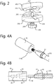
- FIG 4A is a perspective view the connection interface 114a according to an embodiment.
- the connection interface 114a comprises a collector mount 41 and a tapered shaft mount 42.
- the tapered shaft mount 42 is fixed onto or a part of an outer end of the drive shaft 101.
- FIG 4B schematically shows a cross section of the connection interface 114a of Figure 4A .
- the collector mount 41 in this case is a cylinder comprising a recess for receiving part of the tapered shaft mount 42.
- the recess is formed by a tapered socket 44 and a threaded hole 45.
- a keyway 46 is arranged to receive a key 47 from the tapered shaft mount 42.
- Figure 4B shows a draw bar 48 at the outer end of the tapered shaft mount 42 which can be inserted into the threaded hole 45.
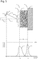
- Figure 5 schematically shows a side view of the collector 1, the fibrous structure and the OMS 108 comprising the laser 8 and the optical sensor 12.
- the optical sensor 12 in this embodiment may be an optical receiver such as a Line-, CCD-, or CMOS sensor.
- a corresponding received radiation intensity is shown as a function of X where X is the distance between the reflecting surface of the object (reflection surface) and the reference point 13 of the OMS 108.
- the graph of Figure 5 shows two curves that are measured on different moments in time.
- Curve 6 is the received radiation as a function of X when the collector is still empty before the electrospinning has started.
- Curve 7 is the received radiation as a function of X when the collector is (partly) covered with a fibrous structure 2 during the electrospinning process, or just after the process has stopped.
- X1 relates to the distance from the reference point 13 of the OMS 108 to the surface of the collector 1 (baseline) and X2 is the distance from the reference point 13 of the OMS 108 to the momentary top layer of the fibrous structure 5.
- the laser beam 9 hits the top layer of the fibrous structure 2.
- the arrow 4 indicates the position of the surface of the collector 1 while the arrow 5 indicates the momentary top layer of the fibrous structure 2.
- the top layer of fibrous structure 2 has an inconsistent fiber density as indicated with fibers 3.
- the laser beam cross section 10 is bigger than the expected pores in the fibrous structure 2.
- Typical values for the cross section of the laser beam 9 are in a range between 25 - 5000 ⁇ m.
- the preferred cross section of the laser beam is large enough to cover a number of fibers and pores at the momentary top layer of the electro spun fibrous structure to yield sufficient reflection (detectable amount of radiation intensity) from the momentary top layer of the electro spun fibrous structure, although small enough to be able to distinguish between small height (distance) differences in a region of interest on the momentary top layer of the electro spun fibrous structure.
- the OMS processes the reflection curve 6 or 7 to determine the distance X1 or X2 corresponding with the first peak in each respective curve, and output this distance value to the processor 111.
- Triangulation methods can be used by the OMS to calculate the values of X1 and X2.
- the processor 111 processes the received distances to calculate the thickness of the fibrous structure.
- a response of a laser triangulation measurement method is a bell-curve (reflection curve) signal resulting from a fibrous (porous) structure that gives little reflection from the top (more porous) layers of fibers, increased reflection from more dense sublayers of fibers, and decreased reflection from deeper layers of the fibrous structure.
- the distance between the reference point 13 of the OMS and the reflection surface of the object (collector 1 or the momentary top layer of the fibrous structure 5) can be derived from the corresponding bell-curves e.g. by taking the position of the peak of the corresponding curves 6 or 7.
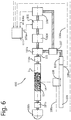
- Figure 6 schematically shows a measuring device 600 for measuring a thickness of a fibrous structure according to an embodiment of the invention.
- the measuring device 600 comprises a frame 107, a rotatable drive shaft 101, a carrier for supporting the fibrous structure, the carrier being detachable from the frame and/or the drive shaft.
- the device 600 also comprises an OMS 108 movably coupled to the frame 107 and arranged to measure a baseline distance between the carrier and the OMS 108 for a plurality of locations on the carrier, and arranged to measure a distance between a top layer of the fibrous structure and the OMS 108 at the plurality of locations.
- the measuring device 600 also comprises a processor 611 arranged to receive the measured baseline distance and the top layer distance for the plurality of locations from the optical measurement system and to calculate a thickness of the electro spun material for all the predefined locations.
- the measuring device 600 resembles the electrospinning device of Figure 3 to a certain extent. However, the measuring device 600 does not comprise the nozzle 51, the container 50, the positioning 112 of the nozzle, the voltage supply system 14 nor the HV contact unit 103. It is noted that the bearing 102b and the mounting element 114b are optional in Figure 6 .
- Figure 7 shows a flow chart of a method of producing a fibrous structure according to an embodiment.
- the method could be performed using the electrospinning device 100.
- the method 400 comprises optically measuring, see block 401, a first (baseline) distance between a collector of an electrospinning device and the optical measurement system for at least one location on a surface of the collector of the electro spinning device.
- Block 401 is followed by creating a fibrous structure on the collector by way of electrospinning, see block 402.
- electrospinning a second (momentary top layer) distance between a momentary top layer of the fibrous structure and the optical measurement system for the at least one location is optically measured, see block 403.
- the measured first and second distance from the optical measurement system are processed for the one or more locations during the electrospinning process to calculate a momentary thickness of the fibrous structure for all the one or more locations, see block 404.
- the method comprises stopping the electrospinning process, see block 405, depending on the determined momentary thickness at at least one of the predefined locations. Electrospinning can be continued at certain areas of the collector while electrospinning at other areas could be stopped depending on the required local thickness.
- Figure 8 shows a flow chart of a method 500 according to a specific embodiment wherein a rotational collector is used.
- the method 500 starts with a block 501 indicating that a collector is attached/fixed to the driveshaft of the setup of Figure 3 .
- the collector 1 is positioned in a desired starting position.
- a block 503 indicates that the readings from sensors 106 and 110 are set to zero in the processor 111.
- a plurality of predefined coordinates is programmed in the processor by e.g. a user. These predefined coordinates can be multiple measurement positions over the circumference of the collector 1. In an embodiment multiple sensors are used to measure distances at different measurement positions in parallel.
- Block 505 indicates that the desired OMS positions (relative to the zero position) at which a measurement acquisition process should be triggered are programmed for OMS positioning. Note that this positioning / position programming is not required when the OMS 108 is at a fixed position.
- a block 506 indicates the starting of the rotation of the collector 1 and to wait for it to reach a desired rotational speed. The rotational angle of the rotating collector 1 can be accurately tracked by readout of the rotational position sensor 106 by the processor 111.
- a block 507 indicates the starting of the measurement process. A measurement point can be defined by the measured distance between the OMS 108 and the reflection surface 4, 5.
- a block 507A indicates the triggering, acquiring and recording of a measurement point for a plurality of predefined coordinates.
- a block 507B indicates that the readings from the OMS 108 can optionally be set to zero in the processor 111.
- a number of measurement points can be taken for a plurality predefined coordinates on an empty collector for averaging purposes (determining the baseline distance), see block 507C.
- Block 508 indicates the starting of the electrospinning process. Fibers will start to collect on the rotating collector 1 forming an electro spun fibrous structure 53 (with uneven distribution on a micro scale). If desired, the nozzle 51 can be positioned at programmed positions or can be moved at a specific speed. Block 509 indicates that during the collection of fibers the distance between OMS and reflection surface is recorded for a plurality of predefined coordinates. As the thickness of the electro spun fibrous structure 53 increases during the electrospinning process, the distance between the OMS 108 and the reflected surface decreases. The momentary thickness of the electro spun fibrous structure may be defined as the momentary distance minus the baseline distance.
- a block 510 indicates that after electrospinning for a desired time, or reaching a desired thickness, the electrospinning process can be stopped (or interrupted).
- the collector 1 keeps rotating after the electrospinning process has stopped, and a number of measurement points at a plurality of predefined coordinates are taken on the electro spun fibrous structure for averaging purposes.
- the measurement process is stopped.
- the rotating is stopped and at block 513 the collector 1 is detached from the driveshaft 101, see also Figure 3 .
- the distance (between the reference point 13 of the OMS and the object (collector 1 or the momentary top layer of the fibrous structure 5) can be derived from the corresponding bell-curves e.g. by taking the position of the peak of the corresponding curves 6 or 7.
- each measured distance is derived from an individual reflection curve detected by the sensor of the OMS, recorded after receiving a trigger to start a measurement acquisition process.
- the distance value X may be derived from the reflection curve by taking the position of the first peak in the reflection curve signal (closest to the OMS). Any additional peaks in the reflection curve signals are left out of account.
- the distance value X relating to the position of the first peak represents the distance between the reference point 13 of the OMS and the object.
- the measurement method/device must have a sufficiently small field of view to detect local variations in thickness. This can be achieved by using a laser spot size suitable for the size of the region of interest.
- contactless measurement method has many advantages. However, contactless methods must allow for sufficient distance between the collector 1 and the OMS 108 to avoid interference of the sensor/device with the electrospinning process since:
- Another solution to avoid interference of the sensor/device with the electrospinning process is to produce the fibrous structure in an electrospinning device which comprises a demountable collector that can be placed into the measuring device 600 shown in Figure 6 .
- the thickness can then be measured using a method as described below.
- Figure 9 shows a method 900 of measuring a thickness of a fibrous structure, the method comprising:
- the method of measuring a thickness of a fibrous structure as shown in Figure 9 is not being performed while producing, so this method is referred to as an offline thickness measuring method.
- the in-situ and offline local thickness measurements described above preferably have a high degree of accuracy over a wide range.
- the thickness of an electro spun structure can be as high as several millimetres while the build-up over time of this structure is determined by the pore size and fiber diameter itself and these typically lie between a few tens of nanometres and a few tens of micrometres.
- the preferred accuracy of thickness measurement for process adjustment or quality control purposes is typically 10 ⁇ m - 50 ⁇ m. This high degree of accuracy may be achieved by:
- any reference signs placed between parentheses shall not be construed as limiting the claim.
- Use of the verb "comprise” and its conjugations does not exclude the presence of elements or steps other than those stated in a claim.
- the article “a” or “an” preceding an element does not exclude the presence of a plurality of such elements.
- several means are enumerated. These means may be embodied by one and the same item of hardware or software. The mere fact that certain measures are recited in mutually different dependent claims does not indicate that a combination of these measures cannot be used to advantage.
Landscapes
- Engineering & Computer Science (AREA)
- Textile Engineering (AREA)
- Mechanical Engineering (AREA)
- Spinning Methods And Devices For Manufacturing Artificial Fibers (AREA)
- Length Measuring Devices By Optical Means (AREA)
- Nonwoven Fabrics (AREA)
Description
- The invention relates to an electrospinning device and a method of producing a fibrous structure using such a device. The invention also relates to a measuring device for measuring a thickness of a fibrous structure and to a method of measuring a thickness of a fibrous structure.
- Electrospinning is a method to produce continuous fibers with a diameter ranging from a few tens of nanometres to a few tens of micrometres. To electrospin fibers, a suitable liquefied material may be fed through a small, electrically conductive nozzle. The liquefied material may be electrically charged by applying a high voltage between the nozzle and a counter electrode. The generated electric field causes a cone-shape deformation of the droplet at the nozzle tip. Once the surface tension of this droplet is overcome by the electrical force, a jet is formed out of the droplet and a fiber forms that moves towards the counter electrode. During the flight towards the counter electrode the fiber is continuously stretched and elongated by the different forces acting on it, reducing its diameter and allowing it to solidify (by evaporation of the solvent or cooling of the material) such that a solid fiber is deposited on the collector (which is placed just before the counter electrode or the counter electrode is used as collector directly).
- When an electrospinning process is run for a certain time, a structure of fibrous layers is formed on the counter electrode or collector. Due to the extremely small fiber diameter and the porous nature of this structure, it is difficult to accurately measure the thickness of the resulting fibrous structure because the structure's surface consists of very thin fibers and is hence compressible. Furthermore, the structure's surface is not smooth but consists of a (random or oriented) mesh of fibers and pores.
- Thickness measurement methods that require direct contact with the structure will yield inaccurate results since the mechanical contact of the measuring device will compress the fibrous structure. Other measuring methods like SEM and light microscopy are destructive since they require slicing of the fibrous structure to allow the measurement system to "look" at the cross-section of the structure.
- Background examples of electrospinning can be found in
US 2013/317285 A1 ,US 2009/130301 A1 andJP 2012 122155 A - Drawback of the known methods for thickness measurement on electrospun fibrous structures is that they can only be applied after the fibrous structure is produced and hence not in situ.
- The present invention provides an electrospinning device that enables in-situ measuring of a thickness of the produced fibrous structure according to claims 1-15.
- A first aspect of the invention provides an electrospinning device comprising:
- a container for holding a liquid comprising a polymer melt or a polymer solution;
- a nozzle arranged to outlet a stream of the liquid from the container;
- a collector for collecting electro spun material coming from the nozzle during an electrospinning process so as to form a fibrous structure on a surface of the collector;
- a voltage supply system arranged to create a voltage difference between the nozzle and the collector,
- an optical measurement system arranged to measure a baseline distance between the surface of the collector and the optical measurement system at at least one predefined location, and to repeatedly measure a momentary distance between a momentary top layer of the fibrous structure and the optical measurement system at the at least one predefined location during the electrospinning process;
- a processor arranged to receive the measured baseline distance and the momentary distance from the optical measurement system and to calculate a momentary thickness of the fibrous structure for the at least one location.
- By using an optical measurement system in an electrospinning device that measures a distance to the collector and a distance to the momentary top layer, an in-situ measurement is possible. A momentary thickness can be calculated at one location or at a plurality of locations. These locations could be predefined by a user or operator by providing one or more coordinates.
- During the electrospinning process, the device is measuring the thickness of the electro spun fibrous structure being produced. This will give an improved control over the production process, as compared to known thickness measurements in which measurements are done after the spinning process. Furthermore, the fibrous structure does not need to be touched or cut into pieces. The thickness can be measured very accurately by measuring the distance from the collector to the optical measurement system and the distance from the (momentary) top layer to the optical measurement system at the at least one location. By also measuring the distance from the collector to the optical measurement system, a kind of initial height map or baseline can be made, so that fluctuations in the collector surface are corrected for. In case the collector is a rotatable collector, the fluctuations due to of axis orientation of the collector can also be compensated for.
- In an embodiment, the collector is movably arranged relative to the nozzle. In this way relatively large collectors can be used that may be covered with electro spun material over a wide area resulting in large fibrous structures. Furthermore, by moving the nozzle relative to the collector, both even and uneven distribution of fibers and thus structure thickness on the collector are possible.
- In an embodiment, the optical measurement system is movably arranged relative to the surface of the collector. In this way, one measurement system can be used to measure at several locations on the collector. Alternatively, the optical measurement system is statically arranged relative to a surface of the collector so as to measure at a single location. In this embodiment, no moving device element are needed and the measurement system will be able to very accurately measure a distance in situ. Optionally, several measurement systems may be used, such as several triangulation sensors, arranged at different predefined locations relative to the collector.
- In an embodiment, the processor is arranged to control at least one out of the following:
- the voltage difference;
- a material feed through the nozzle;
- a nozzle position relative to the collector;
- So in this embodiment, the feedback of the momentary thickness is used to control or adjust the voltage difference and/or the material feed and/or the nozzle position relative to the collector. This online feedback of the measured thickness results in a controlled production of the structure and enables a continuation of the spinning process towards a predefined target structure thickness. Besides, a reduction of waste of electrospinning material may be achieved as compared to known devices.
- In an embodiment the processor is arranged to control the voltage supply system so as to stop the electrospinning process once a required thickness of the fibrous structure has been reached. This provides for the ability to continue the spinning process towards a predefined structure thickness. Also an additional reduction of waste of electrospinning material may be achieved.
- In embodiment for reference only and not part of the invention, the processor is arranged to control a movement of the collector relative to the nozzle so as to produce different thickness of the fibrous structure at different locations. In this way, more complex fiber structures can be created that have different thickness at different locations.
- In an embodiment for reference only and not part of the invention, the collector is rotatable around a rotation axis. The collector may be cylindrical or have a more complex freeform shape. When using such rotating shapes, a multiple number of structures are conceivable. A relatively simple structure may be a tubular structure that could be used as a stent in the medical field. The tubular structure may also be cut and flattened after the spinning process to create a substantially flat layer of electro spun material.
- In an embodiment for reference only and not part of the invention, the optical measurement system comprises a laser device and an optical sensor, wherein the laser device is arranged to send a light beam towards the collector and the sensor is arranged to measure reflected radiation coming from the collector and/or the fibrous structure.
- As mentioned above, optical measurement makes contactless measurement possible and no damage to the fibrous structure will occur. The optical system may comprise a laser and an optical sensor that can be placed at a certain distance away from the collector to avoid interference of the measurement system during the electrospinning process.
- In an embodiment for reference only and not part of the invention, the optical sensor is a 1D or 2D sensor array arranged to detect radiation along at least one axis, wherein the processor is arranged to translate radiation intensities along the axis of the sensor into a reflection curve and to detect a first peak in the reflection curve, wherein the first peak is used by the processor to determine the distance between either the collector or the momentary top layer of the fibrous structure and the optical measurement system.
- By using the first peak of the reflection curve, a reproducible distance measurement for the different types of reflection surfaces, being solid or porous, is possible.
- In an embodiment for reference only and not part of the invention, the optical measurement system comprises a laser triangulation sensor. Such a sensor is both contactless, accurate and cost-effective. Moreover, a relatively long distance between the optical measurement system and the collector can be used so that interference of the measurement device with can be avoided.
- In an embodiment for reference only and not part of the invention, the laser device is arranged to produce a laser beam having a cross section between 25 µm and 5000 µm, preferably between 70 and 2500 µm. The spot produced by the laser may be circular-, oval- or line shaped. The preferred cross section of the laser beam is large enough to cover a number of fibers and pores at the momentary top layer of the electro spun fibrous structure to yield sufficient reflection (detectable amount of radiation intensity) from the momentary top layer of the electro spun fibrous structure, although small enough to be able to distinguish between small height (distance) differences in a region of interest on the momentary top layer of the electro spun fibrous structure.
- In an embodiment for reference only and not part of the invention, the device comprises a user interface wherein the processor is arranged to receive predefined coordinates from a user via the user interface. The user may freely select one or more coordinates at which the thickness of the fibrous structure is calculated. Selection of the coordinates may be done by the user or operator interacting with control software loaded on the processor prior to the measurement.
- In an embodiment, the electrospinning device further comprises a position measurement system arranged to measure a position of the collector relative to the optical measurement system. The processor may then be arranged to receive position information from the position measurement system and to trigger the optical measurement system in dependency on the received position information. A user may define some measurement locations on the collector at which a measurement is desired. These locations may be programmed in a so-called trigger controller incorporated in the processor that triggers the acquisition of a measurement point with the optical measurement system on the selected measurement positions. In this way it is possible to measure repeatedly and accurately at exactly the predefined coordinates.
- According to a further aspect there is provided a measuring device for measuring a thickness of a fibrous structure, the measuring device comprising:
- a frame;
- optionally, a rotatable drive shaft;
- a carrier for supporting the fibrous structure, the carrier being detachable from the frame and/or the drive shaft;
- an optical measurement system movably coupled to the frame and arranged to measure a baseline distance between the carrier and the optical measurement system for at least one location on the carrier, and arranged to measure a top layer distance between a top layer of the fibrous structure and the optical measurement system, at the at least one locations, and
- a processor arranged to receive the measured baseline distance and the top layer distance for the at least one location from the optical measurement system and to calculate a thickness of the fibrous structure for all the locations.
- The measuring device can be used to calculate a thickness of an electro spun fibrous structure produced in an electrospinning device. The electro spun fibrous structure can be transported from the electrospinning device to the measurement device by detaching the collector from the electrospinning device, and by attaching (i.e. mounting) the collector (with the fibrous structure on it) to the measurement device. In this way, the fibrous structure does not need to be removed from the collector and thus not need to be touched, thereby avoiding damages to the fibrous structure.
- In an embodiment the measuring device further comprises a position measurement system arranged to measure a position of the carrier relative to the optical measurement system, wherein the processor is arranged to receive position information from the position measurement system and to trigger the optical measurement system in dependency on the received position information. The position-based triggering of the optical measurement system enables an accurate repetition of the measurements at the predefined coordinates (e.g. to measure baseline and top layer distance at exactly the same coordinate so the difference calculation is representative for the thickness of the fibrous structure at that coordinate).
- In an embodiment, the measuring device comprises a mounting system to install the carrier with a fixed orientation relative to the frame.
- In an embodiment, the carrier is movable relative to the optical measurement system in at least one dimension. This enables the measuring of the thickness for multiple coordinates.
- In an embodiment, the carrier is substantially cylindrical and rotatable relative to the optical measurement system. This enables the measuring of tubular structures or other freeform or 3D structures.
- According to a further aspect there is provided a method of producing a fibrous structure, the method comprising:
- providing an electrospinning device comprising a collector and an optical measurement system;
- optically measuring a baseline distance between the collector and the optical measurement system for at least one location on a surface of the collector;
- creating an electro spun fibrous structure on the collector by way of electrospinning using the electrospinning device;
- and while electrospinning, optically measuring a momentary distance between a momentary top layer of the fibrous structure and the optical measurement system for the at least one location;
- processing the measured baseline distance and the momentary distance for the at least one location during the electrospinning process to calculate a momentary thickness of the fibrous structure for the at least one location.
- In an embodiment the method comprises:
- stopping the electrospinning process, or only continuing electrospinning at certain areas of the collector, depending on the calculated momentary thickness.
- According to yet a further aspect, there is provided a method of measuring a thickness of a fibrous structure, the method comprising:
- mounting a collector without an electro spun fibrous structure on it into a measurement device comprising an optical measurement system;
- optically measuring a baseline distance between a surface of the collector and the optical measurement system at at least one location on the collector;
- removing the collector from the measurement device and placing the collector in an electrospinning device for creation of an electro spun fibrous structure on the collector;
- mounting the collector with the electro spun fibrous structure on it into the measurement device;
- optically measuring a top layer distance between a top layer of the fibrous structure and the optical measurement system at the at least one location;
- processing the measured baseline distance and the top layer distance for the at least one location to calculate a thickness of the fibrous structure.
- This method may be applied to check the quality of electro spun fibrous structures by comparing the actual thickness with a desired or required value. An advantage of this method is that it allows for using special measurement devices that comprise measuring configurations not possible in the electrospinning devices that may have insufficient space for a measurement device.
- These and other aspects of the invention are apparent from and will be elucidated with reference to the embodiments described hereinafter. In the drawings,
-
Figure 1 schematically shows a side view of a first embodiment of the electrospinning device; -
Figure 2 shows a perspective view of the mounting system used inFigure 1 according to an embodiment; -
Figure 3 (reference example only) schematically shows a further embodiment of the electrospinning device; -
Figure 4A is a perspective view the connection interface according to an embodiment; -
Figure 4B schematically shows a cross section of the connection interface ofFigure 4A ; -
Figure 5 (reference example only) schematically shows a side view of the collector, the fibrous structure and the optical measurement system comprising the laser and the optical sensor; -
Figure 6 schematically shows a measuring device for measuring a thickness of a fibrous structure according to an embodiment of the invention; -
Figure 7 shows a flow chart of a method of producing a fibrous structure according to an embodiment; -
Figure 8 (reference example only) shows a flow chart of a method according to a specific embodiment wherein a rotational collector is used, and -
Figure 9 shows a method of measuring a thickness of a fibrous structure according to an embodiment. - It should be noted that items which have the same reference numbers in different Figures, have the same structural features and the same functions, or are the same signals. Where the function and/or structure of such an item has been explained, there is no necessity for repeated explanation thereof in the detailed description.
-
Figure 1 schematically shows a side view of a first embodiment of theelectrospinning device 100. In this example, thedevice 100 comprises acontainer 50 for holding a liquid comprising a polymer melt or a polymer solution, and anozzle 51 arranged to outlet a stream of the liquid from thecontainer 50. It should be noted that thecontainer 50 can be arranged remote from thenozzle 51 wherein it is in fluidic connection with thenozzle 51 by means of for example a tube. Thedevice 100 further comprises acollector 1 for collecting electro spun material coming from thenozzle 51 during an electrospinning process. Avoltage supply system 14 is arranged to create a voltage difference between thenozzle 51 and thecollector 1. Thevoltage supply system 14 may comprise one AC or DC voltage supply to create the voltage difference or it may comprise two voltage supplies, one creating a voltage difference between thecollector 1 and ground and one creating a difference between thenozzle 51 and ground. Due to the applied voltage(s), an electro spunfiber 52 is created that flies from thenozzle 51 to thecollector 1 on which it is collected to form an electro spunfibrous structure 53. - The
electrospinning device 100 also comprises an optical measurement system (OMS) 108 (reference example only) arranged to measure a distance between thecollector 1 or the electro spunfibrous structure 53 and areference point 13 of theOMS 108. In this example, theOMS 108 comprises alaser 8 and anoptical sensor 12. Thereference point 13 is situated at the front of theoptical sensor 12. It is noted that thereference point 13 can be located at other locations, as will be clear to the skilled person. Thereference point 13 can be used in the processing of the measured signals in order to calculate an absolute distance if needed. Thelaser 8 is arranged to create alaser beam 9 which is directed to thecollector 1 and depending on the situation, hits theempty collector 1 or the electro spunfibrous structure 53 at ameasurement position 54. Themeasurement position 54 can correspond to a predefined coordinate at which a distance measurement is to be taken. Thelaser beam 8 is reflected by the collector and/or by the electro spunfibrous structure 53 on thecollector 1 and is detected by theoptical sensor 12 as a reflectedbeam 11. - The
electrospinning device 100 also comprises aprocessor 111. Theprocessor 111 is arranged to receive the measured distances for at least one location on thecollector 1 from theOMS 108 before the electrospinning process and also during the electrospinning process. Theprocessor 111 is arranged to calculate a momentary thickness during the electrospinning process of the fibrous structure for the at least one location using the received distances. - The
electrospinning device 100 may comprise ametrology frame 107 arranged to support thecollector 1 and theOMS 108. In the example ofFigure 1 , theOMS 108 can be moved and positioned relative to themetrology frame 107 by means ofOMS positioning module 109 indicated inFigure 1 by way ofarrows 109. Thearrows 109 indicate that the movement of theOMS 108 relative to themetrology frame 107 is possible in up to six degrees of freedom (DOF). As shown by threeother arrows 112, thenozzle 51 can be positioned relative to theOMS 108, i.e. relative to thesensor 12. So, this positioning is also possible in up to 6 DOF. It is noted that the above mentioned relative positioning of theOMS 108 and of thenozzle 51 are optional and that the different elements shown inFigure 1 could all be fixed to theframe 107. To be able to produce a fiber layer on multiple areas on thecollector 1, it is preferred that thenozzle 51 is able to move relative to thecollector 1. This may be done using the above mentioned positioning means or a different separate system (not shown) arranged to move the collector relative to theframe 107. It is noted that thecollector 1 inFigure 1 may have a top surface with different shapes such as rectangular, square shaped, disc shaped or any other suitable form depending on the structure to be produced. The top surface could be flat or curved. The collector could also have indentations or recesses, and/or it may have extensions so as to create different fibrous structures. In the embodiment ofFigure 1 , the collector is mounted onto theframe 107 by means of a mounting system comprising amount top element 201 and amount bottom element 202. The mounting system is arranged to removably position thecollector 1 relative to theframe 107. In an embodiment the mounting system is a kinematic coupling system. -
Figure 2 shows a perspective view of the mounting system used inFigure 1 according to an embodiment. In this example, the mounting system is a kinematic coupling system comprising atop element 201 and abottom element 202. Thetop element 201 comprises threesemi-spherical elements 203 while thebottom element 202 comprises threegrooves 204. Thebottom element 202 comprises anorientation pin 205, while thetop element 201 comprises aclearance hole 206 cooperating with theorientation pin 206. Thetop element 201 comprises threadedhole 207 for receiving an outer end of adrawbar 208, thedraw bar 208 being biased by means of a spring 209.Thetop element 201 can only be positioned and connected in one way on top of thebottom element 202. This is due to the orientation pin falling in theclearance hole 206 and thesemi-spherical elements 203 falling in the grooves 204.The positioning of the mounting elements relative to each other is very accurate and reproducible as will be appreciated by the skilled person. It is noted that other types of mounting systems are conceivable. - It is also noted that the mounting system 201,202 is optional, however its presence will enable the user to remove the
collector 1 from the electrospinning device and place it into another device for measuring purposes or other operations on the fibrous structure in which accurate alignment is preferred. -
Figure 3 schematically shows a further embodiment of theelectrospinning device 100. In this embodiment, theelectrospinning device 100 comprises a substantiallycylindrical collector 1 which is rotatable relative to the nozzle 51 (reference example only). In this way, a cylindrical fibrous structure can be created during an electrospinning process. Since thecollector 1 is rotatable, it is also referred to as therotating mandrel 1. Thenozzle 51 is also referred to as thespinneret 51 which may be charged with a high voltage for fiber fabrication similar to the process described with reference toFigure 1 . - As shown in
Figure 3 , anelectrospun fiber 52 is ejected as a droplet at (a tip of) thenozzle 51 and it flies from thenozzle 51 to thecollector 1 while it stretches and solidifies in an electrostatic field between the chargednozzle 51 and the chargedcollector 1. On an outer surface of thecollector 1 electrospun fibers are collected that form aporous fibrous layer 53 on thecollector 1, also referred to as electro spunfibrous structure 53. - The
electrospinning device 100 also comprises adrive shaft 101 connecting thecollector 1 to actuator components 102-106. The actuator components in this example comprise amongst others twobearings bearing 102b is optional. Thebearings drive shaft 101 that holds therotating collector 1. Each bearing is arranged on one end of thecollector 1. Theelectrospinning device 100 also comprises a HV (high voltage)contact unit 103 arranged to provide a high-voltage or a grounded connection to therotating collector 1. AnHV isolating transmission 104 is arranged to decouple the HV-chargedcollector 1 from amotor 105 so as to protect themotor 105. Themotor 105 may be a DC, AC, a stepper, or a servomotor. - In the embodiment of
Figure 3 , thedevice 100 comprises a first connectinginterface 114a and asecond connection interface 114b. The first connectinginterface 114a and thesecond connection interface 114b are also referred to as the mounting system 114. The mounting system is arranged to removably mount thecollector 1 into thedevice 100. The mounting system 114 is preferably arranged to fix thecollector 1 onto theshaft 101 in 6 DOF. So for example, the first connectinginterface 114a may cause thecollector 1 to be fixed in 4 DOF while thesecond connection interface 114b is arranged to fix the collector in 2 DOF. It is noted that thebearing 102b is optional and in that situation the second connectinginterface 114b is absent; in that case the first connection interface may be arranged to fixate thecollector 1 relative to theshaft 101 in 6 DOF. - The
electrospinning device 100 also comprises aprocessor 111. Theprocessor 111 may be arranged to send amotor setpoint signal 105a to themotor 105. Thesetpoint signal 105a may comprise position and/or velocity information.
The actuator components further comprise arotational position sensor 106, which may be a rotational encoder (absolute or incremental). Therotational position sensor 106 is arranged to send arotational position signal 106a to theprocessor 111 that can be used by theprocessor 111 to trigger a measurement acquisition process at a predefined coordinate. During the measurement acquisition process a trigger is sent by theprocessor 111 to theOMS 108. At receipt of the trigger theOMS 108 takes a sample of the momentary distance value X and sends it back to theprocessor 111. In an embodiment, theOMS 108 is arranged to sample at a rate above 50 kHz; for high collector positioning speeds the sample rate is typically between 100-400 kHz. An OMS with such a high sample rate enables a thickness measurement at relatively high collector positioning speeds. Sample rates below 50 kHz are possible for situations where the measured positions are static. - The
electrospinning device 100 also comprises ametrology frame 107 that, in this embodiment, forms the frame of reference for all measurements. AnOMS 108 is arranged on the opposite side of therotating collector 1 as compared to thenozzle 51. As a result, a measuredposition 54 is located at the other side of therotating collector 1 as compared to the fiber collection side of therotating collector 1. It is noted that theOMS 108 does not need to be arranged opposite the nozzle but that it is preferred that theOMS 108 is located at such a position that it does not interfere with the fiber production process by thenozzle 51. As was shown in the embodiment ofFigure 1 , theOMS 108 may even be located at the same side as the nozzle relative to the collector 1 (i.e. mandrel). The OMS 108 (reference example only) may determine a thickness of the produced electro spunfibrous structure 53 by means of several techniques e.g. Laser Triangulation, Spectral Interference (Laser) Displacement, or Time Of Flight. Please note that the mentioned techniques could also be used in parallel. - The measured
position 54 can either be a single position or multiple positions to examine the distribution of the fibrous layer buildup. This enables the device or the user thereof to produce a fibrous structure according to pre-defined thickness specifications. Preferably, the measurement is performed perpendicular to a local curvature of thecollector 1. In this way no correction for a possible angle deviation is required on the calculation of a thickness value. - In the embodiment of
Figure 3 , theOMS 108 sends a distancemeasurement sensor signal 108a to theprocessor 111, which will process these signals together with theposition information 106a. - The
electrospinning device 100 also comprises anOMS positioning module 109. The position of theOMS 108 can be fixed relative to a main axis of therotating collector 1. In this case only a single position along the main axis can be measured. Alternatively, the position of theOMS 108 can be automatically adjusted by means of theOMS positioning module 109 when a number of measurement positions along the main axis is required. - The
processor 111 may be arranged to send an OMSpositioning setpoint signal 109a to theOMS positioning module 109. This OMSpositioning setpoint signal 109a may comprise position and/or velocity information. - The
electrospinning device 100 also comprises anOMS position sensor 110, which may be a linear encoder. TheOMS position sensor 110 measures a position of theoptical measurement system 108 relative to themetrology frame 107 and thus to therotating collector 1. TheOMS position sensor 110 may be arranged to send anOMS position signal 110a to theprocessor 111 that can be used by theprocessor 111 for triggering a measurement acquisition process at a predefined coordinate. - In this embodiment, the
electrospinning device 100 also comprises anozzle positioning module 112. It is noted that thenozzle 51 can be fixed relative to therotating collector 1. Alternatively, the position of thenozzle 51 can be automatically adjusted by means of thenozzle positioning module 112, resulting in wider and/or more homogenous coverage of therotating collector 1 with an electro spun fibrous structure. - The
processor 111 may be arranged to send a nozzlepositioning setpoint signal 112a to thenozzle positioning module 112. This nozzlepositioning setpoint signal 112a may comprise position or velocity information. - In the embodiment of
Figure 3 , theelectrospinning device 100 also comprises anozzle position sensor 113, which may be a linear encoder, or a rotational encoder combined with a linear driver belt. Thenozzle position sensor 113 may be arranged to send anozzle position signal 113a to theprocessor 111. Thenozzle position signal 113a may comprise position or velocity information. - In an embodiment, the
processor 111 is arranged for performing the following functions: - receive the predefined coordinates from the user or operator;
- setpoint generation for the
actuators - data recording from the
position sensors - triggering of measurement acquisition;
- data recording from distance sensor(s) 108;
- thickness calculation THK = X2 - X1.
-
Figure 4A is a perspective view theconnection interface 114a according to an embodiment. Theconnection interface 114a comprises acollector mount 41 and atapered shaft mount 42. The taperedshaft mount 42 is fixed onto or a part of an outer end of thedrive shaft 101. -
Figure 4B schematically shows a cross section of theconnection interface 114a ofFigure 4A . As can be seen fromFigure 4B , thecollector mount 41 in this case is a cylinder comprising a recess for receiving part of the taperedshaft mount 42. The recess is formed by a taperedsocket 44 and a threadedhole 45. Akeyway 46 is arranged to receive a key 47 from the taperedshaft mount 42.Figure 4B shows adraw bar 48 at the outer end of the taperedshaft mount 42 which can be inserted into the threadedhole 45. By inserting the taperedshaft mount 42 into thecollector mount 41, the collector will be mounted onto the drive shaft with a high degree of positioning accuracy, preferably in 6 DOF. -
Figure 5 (reference example only) schematically shows a side view of thecollector 1, the fibrous structure and theOMS 108 comprising thelaser 8 and theoptical sensor 12. Theoptical sensor 12 in this embodiment may be an optical receiver such as a Line-, CCD-, or CMOS sensor. At the bottom ofFigure 5 , a corresponding received radiation intensity is shown as a function of X where X is the distance between the reflecting surface of the object (reflection surface) and thereference point 13 of theOMS 108. The graph ofFigure 5 shows two curves that are measured on different moments in time.Curve 6 is the received radiation as a function of X when the collector is still empty before the electrospinning has started.Curve 7 is the received radiation as a function of X when the collector is (partly) covered with afibrous structure 2 during the electrospinning process, or just after the process has stopped. InFigure 5 , X1 relates to the distance from thereference point 13 of theOMS 108 to the surface of the collector 1 (baseline) and X2 is the distance from thereference point 13 of theOMS 108 to the momentary top layer of thefibrous structure 5. - At the top part of
Figure 5 , thelaser beam 9 hits the top layer of thefibrous structure 2. Thearrow 4 indicates the position of the surface of thecollector 1 while thearrow 5 indicates the momentary top layer of thefibrous structure 2. - The top layer of
fibrous structure 2 has an inconsistent fiber density as indicated withfibers 3. According to an embodiment, the laserbeam cross section 10 is bigger than the expected pores in thefibrous structure 2. Typical values for the cross section of thelaser beam 9 are in a range between 25 - 5000 µm. The preferred cross section of the laser beam is large enough to cover a number of fibers and pores at the momentary top layer of the electro spun fibrous structure to yield sufficient reflection (detectable amount of radiation intensity) from the momentary top layer of the electro spun fibrous structure, although small enough to be able to distinguish between small height (distance) differences in a region of interest on the momentary top layer of the electro spun fibrous structure. - Please note that in
Figure 5 , the cross section of thebeam 9 is exaggerated at the end by the oval 10. - In an embodiment the OMS processes the
reflection curve processor 111. Triangulation methods can be used by the OMS to calculate the values of X1 and X2. Theprocessor 111 processes the received distances to calculate the thickness of the fibrous structure. The thickness THK, seeFigure 5 , is determined using the formula: THK = X2 - X1. - The inventors have realized that a response of a laser triangulation measurement method (reference only) is a bell-curve (reflection curve) signal resulting from a fibrous (porous) structure that gives little reflection from the top (more porous) layers of fibers, increased reflection from more dense sublayers of fibers, and decreased reflection from deeper layers of the fibrous structure. The distance (between the
reference point 13 of the OMS and the reflection surface of the object (collector 1 or the momentary top layer of the fibrous structure 5) can be derived from the corresponding bell-curves e.g. by taking the position of the peak of thecorresponding curves -
Figure 6 (reference example only) schematically shows ameasuring device 600 for measuring a thickness of a fibrous structure according to an embodiment of the invention. In this embodiment, the measuringdevice 600 comprises aframe 107, arotatable drive shaft 101, a carrier for supporting the fibrous structure, the carrier being detachable from the frame and/or the drive shaft. Thedevice 600 also comprises anOMS 108 movably coupled to theframe 107 and arranged to measure a baseline distance between the carrier and theOMS 108 for a plurality of locations on the carrier, and arranged to measure a distance between a top layer of the fibrous structure and theOMS 108 at the plurality of locations. The measuringdevice 600 also comprises aprocessor 611 arranged to receive the measured baseline distance and the top layer distance for the plurality of locations from the optical measurement system and to calculate a thickness of the electro spun material for all the predefined locations. - As can be seen from
Figure 6 , the measuringdevice 600 resembles the electrospinning device ofFigure 3 to a certain extent. However, the measuringdevice 600 does not comprise thenozzle 51, thecontainer 50, the positioning 112 of the nozzle, thevoltage supply system 14 nor theHV contact unit 103. It is noted that thebearing 102b and the mountingelement 114b are optional inFigure 6 . -
Figure 7 shows a flow chart of a method of producing a fibrous structure according to an embodiment. The method could be performed using theelectrospinning device 100. Themethod 400 comprises optically measuring, seeblock 401, a first (baseline) distance between a collector of an electrospinning device and the optical measurement system for at least one location on a surface of the collector of the electro spinning device.Block 401 is followed by creating a fibrous structure on the collector by way of electrospinning, seeblock 402. While electrospinning, a second (momentary top layer) distance between a momentary top layer of the fibrous structure and the optical measurement system for the at least one location is optically measured, seeblock 403. The measured first and second distance from the optical measurement system are processed for the one or more locations during the electrospinning process to calculate a momentary thickness of the fibrous structure for all the one or more locations, seeblock 404. Optionally the method comprises stopping the electrospinning process, seeblock 405, depending on the determined momentary thickness at at least one of the predefined locations. Electrospinning can be continued at certain areas of the collector while electrospinning at other areas could be stopped depending on the required local thickness. -
Figure 8 (reference example only) shows a flow chart of amethod 500 according to a specific embodiment wherein a rotational collector is used. Themethod 500 starts with ablock 501 indicating that a collector is attached/fixed to the driveshaft of the setup ofFigure 3 . Next, in astep 502, thecollector 1 is positioned in a desired starting position. Ablock 503 indicates that the readings fromsensors processor 111. At block 504 a plurality of predefined coordinates is programmed in the processor by e.g. a user. These predefined coordinates can be multiple measurement positions over the circumference of thecollector 1. In an embodiment multiple sensors are used to measure distances at different measurement positions in parallel.Block 505 indicates that the desired OMS positions (relative to the zero position) at which a measurement acquisition process should be triggered are programmed for OMS positioning. Note that this positioning / position programming is not required when theOMS 108 is at a fixed position. Ablock 506 indicates the starting of the rotation of thecollector 1 and to wait for it to reach a desired rotational speed. The rotational angle of therotating collector 1 can be accurately tracked by readout of therotational position sensor 106 by theprocessor 111. A block 507 indicates the starting of the measurement process. A measurement point can be defined by the measured distance between theOMS 108 and thereflection surface OMS 108 can optionally be set to zero in theprocessor 111. - A number of measurement points can be taken for a plurality predefined coordinates on an empty collector for averaging purposes (determining the baseline distance), see block 507C.
-
Block 508 indicates the starting of the electrospinning process. Fibers will start to collect on therotating collector 1 forming an electro spun fibrous structure 53 (with uneven distribution on a micro scale). If desired, thenozzle 51 can be positioned at programmed positions or can be moved at a specific speed.Block 509 indicates that during the collection of fibers the distance between OMS and reflection surface is recorded for a plurality of predefined coordinates. As the thickness of the electro spunfibrous structure 53 increases during the electrospinning process, the distance between theOMS 108 and the reflected surface decreases. The momentary thickness of the electro spun fibrous structure may be defined as the momentary distance minus the baseline distance. Ablock 510 indicates that after electrospinning for a desired time, or reaching a desired thickness, the electrospinning process can be stopped (or interrupted). Optionally, thecollector 1 keeps rotating after the electrospinning process has stopped, and a number of measurement points at a plurality of predefined coordinates are taken on the electro spun fibrous structure for averaging purposes. Atblock 511 the measurement process is stopped. Atblock 512 the rotating is stopped and at block 513 thecollector 1 is detached from thedriveshaft 101, see alsoFigure 3 . The distance (between thereference point 13 of the OMS and the object (collector 1 or the momentary top layer of the fibrous structure 5) can be derived from the corresponding bell-curves e.g. by taking the position of the peak of thecorresponding curves - In an embodiment, each measured distance is derived from an individual reflection curve detected by the sensor of the OMS, recorded after receiving a trigger to start a measurement acquisition process. The distance value X may be derived from the reflection curve by taking the position of the first peak in the reflection curve signal (closest to the OMS). Any additional peaks in the reflection curve signals are left out of account. The distance value X relating to the position of the first peak represents the distance between the
reference point 13 of the OMS and the object. - If the
sensor 12 and thecollector surface 4 are able to move relatively to each other, distance information at different spatial coordinates can be obtained. In this way accurate measurement of structure thickness at different spatial coordinates on the structure can be achieved. In such cases the measurement method/device must have a sufficiently small field of view to detect local variations in thickness. This can be achieved by using a laser spot size suitable for the size of the region of interest. - The contactless measurement method described above has many advantages. However, contactless methods must allow for sufficient distance between the
collector 1 and theOMS 108 to avoid interference of the sensor/device with the electrospinning process since: - The
device 100 can alter the electric field when it is too close to thenozzle 51 orcollector 1; - The
device 100 can build up static electric charge and starting to act as an electrode (attracting or repelling fibers onto the device rather than on the collector); - The
device 100 can get damaged by electric discharges between the (high voltage)nozzle 51 orcollector 1 and thedevice 100. - Another solution to avoid interference of the sensor/device with the electrospinning process is to produce the fibrous structure in an electrospinning device which comprises a demountable collector that can be placed into the measuring
device 600 shown inFigure 6 . The thickness can then be measured using a method as described below. -
Figure 9 shows amethod 900 of measuring a thickness of a fibrous structure, the method comprising: - mounting a collector without an electrospun structure on it into a measurement device comprising an optical measurement system, see
block 901 - optically measuring a baseline distance between a surface of the collector and the optical measurement system at at least one location on the collector, see
block 902; - removing the collector from the measurement device and placing the collector in an electrospinning device for creation of an electro spun structure on the collector, see
block 903; - mounting the collector with the electrospun structure on it into the measurement device, see
block 904; - optically measuring a top layer distance between a top layer of the fibrous structure and the optical measurement system at the at least one location, see
block 905; - processing the measured baseline and top layer distance for the at least one location from the optical measurement system to determine a thickness of the fibrous structure, see
block 906. - The method of measuring a thickness of a fibrous structure as shown in
Figure 9 is not being performed while producing, so this method is referred to as an offline thickness measuring method. - The in-situ and offline local thickness measurements described above preferably have a high degree of accuracy over a wide range. The thickness of an electro spun structure can be as high as several millimetres while the build-up over time of this structure is determined by the pore size and fiber diameter itself and these typically lie between a few tens of nanometres and a few tens of micrometres. The preferred accuracy of thickness measurement for process adjustment or quality control purposes is typically 10 µm - 50µm. This high degree of accuracy may be achieved by:
- Using accurate distance measurement methods, for instance laser triangulation, spectral interference etcetera;
- Accurate positioning of the collector and the optical measurement system;
- High speed triggering of measurement acquisition for increased repeatability accuracy at high positioning speeds of the OMS and/or the collector;
- Ability to average the thickness over numerous measurement points;
- Ability to measure distances over an area that in average is representative for the region of interest.
- It should be noted that the above-mentioned embodiments illustrate rather than limit the invention, and that those skilled in the art will be able to design many alternative embodiments.
- In the claims, any reference signs placed between parentheses shall not be construed as limiting the claim. Use of the verb "comprise" and its conjugations does not exclude the presence of elements or steps other than those stated in a claim. The article "a" or "an" preceding an element does not exclude the presence of a plurality of such elements. In the device claims several means are enumerated. These means may be embodied by one and the same item of hardware or software. The mere fact that certain measures are recited in mutually different dependent claims does not indicate that a combination of these measures cannot be used to advantage.
Claims (15)
- An electrospinning device (100) comprising:- a container (50) for holding a liquid comprising a polymer melt or a polymer solution;- a nozzle (51) arranged to outlet a stream of the liquid from the container;- a collector (1) for collecting electro spun material coming from the nozzle during an electrospinning process so as to form a fibrous structure on a surface of the collector;- a voltage supply system (14) arranged to create a voltage difference between the nozzle and the collector,- an optical measurement system (8,12;108) arranged to measure a baseline distance between the surface of the collector and the optical measurement system at at least one predefined location, and to repeatedly measure a momentary distance between a momentary top layer of the fibrous structure and the optical measurement system at the at least one predefined location during the electrospinning process- a processor (111) arranged to receive the measured baseline distance and the momentary distance from the optical measurement system and to calculate a momentary thickness of the fibrous structure for the at least one location.
- The electrospinning device according to claim 1, wherein the collector is movably arranged relative to the nozzle.
- The electrospinning device according to claim 1 or 2, wherein the optical measurement system (8,12;108) is movably arranged relative to the surface of the collector (1)
- The electrospinning device according to claim 1, wherein the optical measurement system (8, 12; 108) is statically arranged relative to a surface of the collector (1) so as to measure at a single location.
- The electrospinning device according to any one of the preceding claims, wherein the processor is arranged to control at least one out of the following:- the voltage difference;- a material feed through the nozzle;- a nozzle position relative to the collector;
in dependency on the calculated momentary thickness of the fibrous structure at the at least one of the predefined location. - The electrospinning device according to any one of the preceding claims, wherein the processor is arranged to control the voltage supply system so as to stop the electrospinning process once a required thickness of the fibrous structure has been reached.
- The electrospinning device according to any one of the preceding claims, wherein the optical measurement system (8,12;108) is movable relative to the surface of the collector and is arranged to measure the baseline distance and the momentary distance at a plurality of locations corresponding to a plurality of predefined coordinates.
- A measuring device for measuring a thickness of a fibrous structure, the measuring device comprising:- a frame (107);- optionally, a rotatable drive shaft (101);- a carrier for supporting the fibrous structure, the carrier being detachable from the frame and/or the drive shaft;- an optical measurement system (8,12;108) movably coupled to the frame (107) and arranged to measure a baseline distance between the carrier and the optical measurement system for a plurality of locations on the carrier, and arranged to measure a top layer distance between a top layer of the fibrous structure and the optical measurement system, at the plurality of locations;- a processor (111) arranged to receive the measured baseline distance and the top layer distance for the plurality of locations from the optical measurement system and to calculate a thickness of the fibrous structure for all the locations.
- The measuring device according to claim 8, wherein the device further comprises a position measurement system (106,110) arranged to measure a position of the carrier (1) relative to the optical measurement system (108), wherein the processor (111) is arranged to receive position information from the position measurement system and to trigger the optical measurement system (108) in dependency on the received position information.
- The measuring device according to claim 8 or 9, wherein the device comprises a mounting system to install the carrier with a fixed orientation relative to the frame (107).
- The measuring device according to any of the claims 8-10, wherein the carrier is movable relative to the optical measurement system in at least one direction.
- The measuring device according to any of the claims 10-11, wherein the carrier is substantially cylindrical and rotatable relative to the optical measurement system.
- A method of producing a fibrous structure, the method comprising:- providing an electrospinning device comprising a collector and an optical measurement system according to any one of claims 1-12;- optically measuring a baseline distance between the collector and the optical measurement system for at least one location on a surface of the collector;- creating the fibrous structure on the surface of the collector by way of electrospinning using the electrospinning device;- and while electrospinning, optically measuring a momentary distance between a momentary top layer of the fibrous structure and the optical measurement system for the at least one location;- processing the measured baseline distance and the momentary distance for the at least one location during the electrospinning process to calculate a momentary thickness of the fibrous structure for the at least one location.
- The method of producing according to claim 13, wherein the method comprises:- stopping the electrospinning process, or only continuing spinning at certain areas of the collector, depending on the calculated momentary thickness.
- A method of measuring a thickness of a fibrous structure, the method comprising:- mounting a collector without an electro spun fibrous structure on it into a measurement device comprising an optical measurement system;- optically measuring a baseline distance between a surface of the collector and the optical measurement system at at least one location on the collector;- removing the collector from the measurement device and placing the collector in an electrospinning device for creation of an electro spun fibrous structure on the collector;- mounting the collector with the electro spun fibrous structure on it into the measurement device;- optically measuring a top layer distance between a top layer of the fibrous structure and the optical measurement system at the at least one location;- processing the measured baseline distance and the top layer distance for the at least one location to calculate a thickness of the fibrous structure.
Priority Applications (1)
| Application Number | Priority Date | Filing Date | Title |
|---|---|---|---|
| PL17717752T PL3445897T3 (en) | 2016-04-21 | 2017-04-20 | Electrospinning device and method |
Applications Claiming Priority (2)
| Application Number | Priority Date | Filing Date | Title |
|---|---|---|---|
| NL2016652A NL2016652B1 (en) | 2016-04-21 | 2016-04-21 | Electrospinning device and method. |
| PCT/EP2017/059376 WO2017182560A1 (en) | 2016-04-21 | 2017-04-20 | Electrospinning device and method |
Publications (2)
| Publication Number | Publication Date |
|---|---|
| EP3445897A1 EP3445897A1 (en) | 2019-02-27 |
| EP3445897B1 true EP3445897B1 (en) | 2021-01-13 |
Family
ID=56133013
Family Applications (1)
| Application Number | Title | Priority Date | Filing Date |
|---|---|---|---|
| EP17717752.4A Active EP3445897B1 (en) | 2016-04-21 | 2017-04-20 | Electrospinning device and method |
Country Status (8)
| Country | Link |
|---|---|
| US (1) | US11072873B2 (en) |
| EP (1) | EP3445897B1 (en) |
| CN (1) | CN109563644A (en) |
| ES (1) | ES2863306T3 (en) |
| NL (1) | NL2016652B1 (en) |
| PL (1) | PL3445897T3 (en) |
| WO (1) | WO2017182560A1 (en) |
| ZA (1) | ZA201807009B (en) |
Families Citing this family (11)
| Publication number | Priority date | Publication date | Assignee | Title |
|---|---|---|---|---|
| NL2021681B1 (en) | 2018-09-21 | 2020-05-07 | Innovative Mechanical Engineering Tech B V | Electrospinning method and apparatus |
| CN112709011B (en) * | 2019-10-25 | 2022-07-12 | 中国石油化工股份有限公司 | Process for making polymeric nonwoven tubes |
| US11732383B2 (en) * | 2019-10-28 | 2023-08-22 | Kao Corporation | Method for manufacturing fiber deposition body, method for manufacturing film, and method for attaching film |
| CN114599830B (en) * | 2019-10-28 | 2023-05-12 | 花王株式会社 | Method for producing fiber-deposited body, method for producing film, and method for attaching film |
| CN111020719A (en) * | 2019-12-16 | 2020-04-17 | 大连理工大学 | A device and method for preparing nanofiber membrane with controllable thickness |
| CN113155831B (en) * | 2021-03-31 | 2022-06-24 | 广东工业大学 | Lens reversing fine adjustment mechanism and electrostatic spinning filamentation detection device |
| JP7689302B2 (en) * | 2021-05-19 | 2025-06-06 | パナソニックIpマネジメント株式会社 | Fiber assembly manufacturing apparatus and method |
| US12272576B2 (en) * | 2021-06-18 | 2025-04-08 | Taiwan Semiconductor Manufacturing Company, Ltd. | Apparatus and methods for determining fluid dynamics of liquid film on wafer surface |
| CN114427120B (en) * | 2022-01-27 | 2023-01-06 | 青岛中科凯尔科技有限公司 | System and method for monitoring electrostatic spinning solution coating |
| CN114411273B (en) * | 2022-01-27 | 2022-11-11 | 青岛中科凯尔科技有限公司 | Electrostatic spinning control system |
| CN114775071B (en) * | 2022-03-23 | 2025-03-07 | 北京亿华通科技股份有限公司 | A multi-needle electrospinning device based on variable speed control |
Citations (18)
| Publication number | Priority date | Publication date | Assignee | Title |
|---|---|---|---|---|
| DE10313888A1 (en) | 2003-03-27 | 2004-10-28 | Fraunhofer-Gesellschaft zur Förderung der angewandten Forschung e.V. | Continuous online measurement and regulation of the thickness of a coating to be applied to a technical workpiece uses a triangulation method with an optical sensor arrangement |
| US20050137829A1 (en) | 2003-12-17 | 2005-06-23 | Siemens Westinghouse Power Corporation | System and method for measuring coating thickness |
| RU82035U1 (en) | 2008-08-28 | 2009-04-10 | Юрий Андреевич Сазонов | DEVICE FOR MEASURING THICKNESS OF MOVING FILM (OPTIONS) |
| WO2009049566A2 (en) | 2007-10-18 | 2009-04-23 | Elmarco, S.R.O. | Device for production of layer of nanofibres through electrostatic spinning of polymer matrices and collecting electrode for such device |
| US20090130301A1 (en) | 2007-08-29 | 2009-05-21 | Bayer Materialscience Ag | Apparatus and method for producing electrically conducting nanostructures by means of electrospinning |
| US7758910B2 (en) | 2005-04-29 | 2010-07-20 | National Research Council Of Canada | Method of on-line thickness measurement of applied coatings |
| CN201816214U (en) | 2010-04-30 | 2011-05-04 | 西安工业大学 | Thickness on-line detection sensor used during plastic film preparation process with casting method |
| KR101040064B1 (en) | 2010-12-06 | 2011-06-09 | 신슈 다이가쿠 | Nanofiber manufacturing apparatus and nanofiber manufacturing method |
| KR20110125755A (en) | 2010-05-14 | 2011-11-22 | 삼성전자주식회사 | Power and data transmission apparatus and method using a moving object |
| WO2012097229A2 (en) | 2011-01-14 | 2012-07-19 | Neograft Technologies, Inc. | Apparatus for creating graft devices |
| US20120263866A1 (en) | 2009-10-19 | 2012-10-18 | Torsten Melzer-Jokisch | Method for measuring layer thickness by means of laser triangulation, and device |
| CN103473021A (en) | 2013-07-10 | 2013-12-25 | 杭州安致文化创意有限公司 | Two-dimensional-image-based 3D (three-dimensional) printing system and method |
| EP2650410B1 (en) | 2010-12-06 | 2015-06-10 | Toptec Co., Ltd. | Nanofiber manufacturing device |
| WO2015103277A1 (en) | 2013-12-31 | 2015-07-09 | Neograft Technologies, Inc. | Self-diagnostic graft production systems and related methods |
| EP2987895A1 (en) | 2013-04-17 | 2016-02-24 | Finetex Ene, Inc. | Electrospinning apparatus |
| KR101622054B1 (en) | 2014-12-31 | 2016-05-17 | (재)한국섬유기계연구원 | Manufacturing method, the same and nano fiber manufacturing equipment using electrospinning |
| EP3072997A1 (en) | 2013-11-21 | 2016-09-28 | Finetex Ene, Inc. | Electrospinning device for manufacturing nanofiber |
| EP3072996A1 (en) | 2013-11-21 | 2016-09-28 | Finetex Ene, Inc. | Electrospinning device for manufacturing nanofiber |
Family Cites Families (10)
| Publication number | Priority date | Publication date | Assignee | Title |
|---|---|---|---|---|
| DD151902A1 (en) * | 1980-06-09 | 1981-11-11 | Frank Schumann | METHOD FOR DETERMINING THICKNESS OF ADHESIVE LAYERS ON BOOK BLOCK BACKS |
| US5017869A (en) * | 1989-12-14 | 1991-05-21 | General Electric Company | Swept frequency eddy current system for measuring coating thickness |
| EP0629450B1 (en) * | 1993-05-07 | 2000-06-28 | Nordson Corporation | Powder coating system and powder coating thickness sensor |
| US7939003B2 (en) * | 2004-08-11 | 2011-05-10 | Cornell Research Foundation, Inc. | Modular fabrication systems and methods |
| US9723866B2 (en) * | 2004-08-11 | 2017-08-08 | Cornell University | System and method for solid freeform fabrication of edible food |
| US7981353B2 (en) * | 2005-12-12 | 2011-07-19 | University Of Washington | Method for controlled electrospinning |
| US20110143019A1 (en) * | 2009-12-14 | 2011-06-16 | Amprius, Inc. | Apparatus for Deposition on Two Sides of the Web |
| US9445874B2 (en) * | 2010-07-19 | 2016-09-20 | Neograft Technologies, Inc. | Graft devices and methods of use |
| EP2659034B1 (en) * | 2010-12-29 | 2019-02-20 | University of Pittsburgh - Of the Commonwealth System of Higher Education | System and method for mandrel-less electrospinning |
| CN104764289B (en) * | 2014-08-11 | 2015-12-02 | 无锡美联动线智能科技有限公司 | Refrigerator body posterior medial accumulated ice detection alarm system |
-
2016
- 2016-04-21 NL NL2016652A patent/NL2016652B1/en active
-
2017
- 2017-04-20 CN CN201780033014.5A patent/CN109563644A/en active Pending
- 2017-04-20 PL PL17717752T patent/PL3445897T3/en unknown
- 2017-04-20 ES ES17717752T patent/ES2863306T3/en active Active
- 2017-04-20 WO PCT/EP2017/059376 patent/WO2017182560A1/en not_active Ceased
- 2017-04-20 EP EP17717752.4A patent/EP3445897B1/en active Active
- 2017-04-20 US US16/094,540 patent/US11072873B2/en active Active
-
2018
- 2018-10-19 ZA ZA2018/07009A patent/ZA201807009B/en unknown
Patent Citations (19)
| Publication number | Priority date | Publication date | Assignee | Title |
|---|---|---|---|---|
| DE10313888A1 (en) | 2003-03-27 | 2004-10-28 | Fraunhofer-Gesellschaft zur Förderung der angewandten Forschung e.V. | Continuous online measurement and regulation of the thickness of a coating to be applied to a technical workpiece uses a triangulation method with an optical sensor arrangement |
| US20050137829A1 (en) | 2003-12-17 | 2005-06-23 | Siemens Westinghouse Power Corporation | System and method for measuring coating thickness |
| US7758910B2 (en) | 2005-04-29 | 2010-07-20 | National Research Council Of Canada | Method of on-line thickness measurement of applied coatings |
| US20090130301A1 (en) | 2007-08-29 | 2009-05-21 | Bayer Materialscience Ag | Apparatus and method for producing electrically conducting nanostructures by means of electrospinning |
| JP2013076203A (en) | 2007-08-29 | 2013-04-25 | Bayer Materialscience Ag | Apparatus and method for generating conductive nano structure by electrospinning |
| WO2009049566A2 (en) | 2007-10-18 | 2009-04-23 | Elmarco, S.R.O. | Device for production of layer of nanofibres through electrostatic spinning of polymer matrices and collecting electrode for such device |
| RU82035U1 (en) | 2008-08-28 | 2009-04-10 | Юрий Андреевич Сазонов | DEVICE FOR MEASURING THICKNESS OF MOVING FILM (OPTIONS) |
| US20120263866A1 (en) | 2009-10-19 | 2012-10-18 | Torsten Melzer-Jokisch | Method for measuring layer thickness by means of laser triangulation, and device |
| CN201816214U (en) | 2010-04-30 | 2011-05-04 | 西安工业大学 | Thickness on-line detection sensor used during plastic film preparation process with casting method |
| KR20110125755A (en) | 2010-05-14 | 2011-11-22 | 삼성전자주식회사 | Power and data transmission apparatus and method using a moving object |
| KR101040064B1 (en) | 2010-12-06 | 2011-06-09 | 신슈 다이가쿠 | Nanofiber manufacturing apparatus and nanofiber manufacturing method |
| EP2650410B1 (en) | 2010-12-06 | 2015-06-10 | Toptec Co., Ltd. | Nanofiber manufacturing device |
| WO2012097229A2 (en) | 2011-01-14 | 2012-07-19 | Neograft Technologies, Inc. | Apparatus for creating graft devices |
| EP2987895A1 (en) | 2013-04-17 | 2016-02-24 | Finetex Ene, Inc. | Electrospinning apparatus |
| CN103473021A (en) | 2013-07-10 | 2013-12-25 | 杭州安致文化创意有限公司 | Two-dimensional-image-based 3D (three-dimensional) printing system and method |
| EP3072997A1 (en) | 2013-11-21 | 2016-09-28 | Finetex Ene, Inc. | Electrospinning device for manufacturing nanofiber |
| EP3072996A1 (en) | 2013-11-21 | 2016-09-28 | Finetex Ene, Inc. | Electrospinning device for manufacturing nanofiber |
| WO2015103277A1 (en) | 2013-12-31 | 2015-07-09 | Neograft Technologies, Inc. | Self-diagnostic graft production systems and related methods |
| KR101622054B1 (en) | 2014-12-31 | 2016-05-17 | (재)한국섬유기계연구원 | Manufacturing method, the same and nano fiber manufacturing equipment using electrospinning |
Non-Patent Citations (1)
| Title |
|---|
| AFFANDI NOR DALILA, TRUONG YEN BACH, KYRATZIS ILIAS LOUIS, PADHYE RAJIV, ARNOLD LYNDON: "A non-destructive method for thickness measurement of thin electrospun membranes using white light profilometry", JOURNAL OF MATERIAL SCIENCE, KLUWER ACADEMIC PUBLISHERS, DORDRECHT, vol. 45, no. 5, 1 March 2010 (2010-03-01), Dordrecht , pages 1411 - 1418, XP093195906, ISSN: 0022-2461, DOI: 10.1007/s10853-009-4103-6 |
Also Published As
| Publication number | Publication date |
|---|---|
| WO2017182560A1 (en) | 2017-10-26 |
| PL3445897T3 (en) | 2021-06-28 |
| US20190119830A1 (en) | 2019-04-25 |
| EP3445897A1 (en) | 2019-02-27 |
| ZA201807009B (en) | 2021-05-26 |
| NL2016652A (en) | 2017-11-01 |
| ES2863306T3 (en) | 2021-10-11 |
| CN109563644A (en) | 2019-04-02 |
| US11072873B2 (en) | 2021-07-27 |
| NL2016652B1 (en) | 2017-11-16 |
Similar Documents
| Publication | Publication Date | Title |
|---|---|---|
| EP3445897B1 (en) | Electrospinning device and method | |
| CN102245343B (en) | Method and laser processing machine with means for determining a misalignment of a powder feed nozzle of the laser processing machine | |
| US7942063B2 (en) | Processing apparatus | |
| CN101815596B (en) | Method for determining focus position and method for determining position of laser beam relative to hole and laser processing nozzle | |
| JP6786758B2 (en) | Real-time inspection of automatic ribbon placement | |
| WO2015092442A1 (en) | Additive manufacturing apparatus and method | |
| CN110869149A (en) | Apparatus and method for additive manufacturing | |
| US20190134746A1 (en) | Device for powder bed-based genrative production of metallic components | |
| KR101948939B1 (en) | Method and apparatus for centering of spin finishing of lens | |
| JPWO2005010502A1 (en) | How to replace the probe of a scanning probe microscope | |
| CH698853B1 (en) | Spark machining machine for piece, has detection device including optical detection apparatus visualizing features situated on assemblies along axis to permit evaluation and correction of any relative geometrical drift between assemblies | |
| US11017559B2 (en) | Hole location targets and measurement systems, and methods for measuring a location of a hole | |
| BRPI1007890B1 (en) | device and method for drilling material | |
| EP2522950A1 (en) | Method and device for measuring layer thickness | |
| US7388199B2 (en) | Probe manufacturing method, probe, and scanning probe microscope | |
| KR20130045684A (en) | Probe head and scanning probe microscope employing the same | |
| CN112219085A (en) | 360 degree optical measuring device | |
| JPH11183160A (en) | Form measuring equipment and form measuring method | |
| JP5500653B2 (en) | Position measuring device | |
| BRPI1007891B1 (en) | methods for drilling material | |
| US11248896B2 (en) | Hole location targets and measurement systems, and methods for measuring a location of a hole | |
| JP2002234669A (en) | Device in direct roving winder detecting actual diameter of roving package in non-contact manner, roving winder provided with the same, method for controlling roving winder, and method for controlling spinning assembly | |
| Ismail | Development and characterisation of next generation stylus for micro coordinate measuring machine. | |
| EP4497571A1 (en) | Modular machine for additive manufacturing, subtraction or transformation of material | |
| JP6675121B2 (en) | Sample holding / scanning mechanism, scanning probe microscope, and method of manufacturing probe |
Legal Events
| Date | Code | Title | Description |
|---|---|---|---|
| STAA | Information on the status of an ep patent application or granted ep patent |
Free format text: STATUS: UNKNOWN |
|
| STAA | Information on the status of an ep patent application or granted ep patent |
Free format text: STATUS: THE INTERNATIONAL PUBLICATION HAS BEEN MADE |
|
| PUAI | Public reference made under article 153(3) epc to a published international application that has entered the european phase |
Free format text: ORIGINAL CODE: 0009012 |
|
| STAA | Information on the status of an ep patent application or granted ep patent |
Free format text: STATUS: REQUEST FOR EXAMINATION WAS MADE |
|
| 17P | Request for examination filed |
Effective date: 20181018 |
|
| AK | Designated contracting states |
Kind code of ref document: A1 Designated state(s): AL AT BE BG CH CY CZ DE DK EE ES FI FR GB GR HR HU IE IS IT LI LT LU LV MC MK MT NL NO PL PT RO RS SE SI SK SM TR |
|
| AX | Request for extension of the european patent |
Extension state: BA ME |
|
| DAV | Request for validation of the european patent (deleted) | ||
| DAX | Request for extension of the european patent (deleted) | ||
| GRAP | Despatch of communication of intention to grant a patent |
Free format text: ORIGINAL CODE: EPIDOSNIGR1 |
|
| STAA | Information on the status of an ep patent application or granted ep patent |
Free format text: STATUS: GRANT OF PATENT IS INTENDED |
|
| INTG | Intention to grant announced |
Effective date: 20200806 |
|
| GRAS | Grant fee paid |
Free format text: ORIGINAL CODE: EPIDOSNIGR3 |
|
| GRAA | (expected) grant |
Free format text: ORIGINAL CODE: 0009210 |
|
| STAA | Information on the status of an ep patent application or granted ep patent |
Free format text: STATUS: THE PATENT HAS BEEN GRANTED |
|
| AK | Designated contracting states |
Kind code of ref document: B1 Designated state(s): AL AT BE BG CH CY CZ DE DK EE ES FI FR GB GR HR HU IE IS IT LI LT LU LV MC MK MT NL NO PL PT RO RS SE SI SK SM TR |
|
| REG | Reference to a national code |
Ref country code: GB Ref legal event code: FG4D |
|
| REG | Reference to a national code |
Ref country code: CH Ref legal event code: EP |
|
| REG | Reference to a national code |
Ref country code: IE Ref legal event code: FG4D |
|
| REG | Reference to a national code |
Ref country code: DE Ref legal event code: R096 Ref document number: 602017031344 Country of ref document: DE |
|
| REG | Reference to a national code |
Ref country code: AT Ref legal event code: REF Ref document number: 1354633 Country of ref document: AT Kind code of ref document: T Effective date: 20210215 |
|
| REG | Reference to a national code |
Ref country code: NL Ref legal event code: FP |
|
| REG | Reference to a national code |
Ref country code: AT Ref legal event code: MK05 Ref document number: 1354633 Country of ref document: AT Kind code of ref document: T Effective date: 20210113 |
|
| REG | Reference to a national code |
Ref country code: LT Ref legal event code: MG9D |
|
| PG25 | Lapsed in a contracting state [announced via postgrant information from national office to epo] |
Ref country code: BG Free format text: LAPSE BECAUSE OF FAILURE TO SUBMIT A TRANSLATION OF THE DESCRIPTION OR TO PAY THE FEE WITHIN THE PRESCRIBED TIME-LIMIT Effective date: 20210413 Ref country code: LT Free format text: LAPSE BECAUSE OF FAILURE TO SUBMIT A TRANSLATION OF THE DESCRIPTION OR TO PAY THE FEE WITHIN THE PRESCRIBED TIME-LIMIT Effective date: 20210113 Ref country code: HR Free format text: LAPSE BECAUSE OF FAILURE TO SUBMIT A TRANSLATION OF THE DESCRIPTION OR TO PAY THE FEE WITHIN THE PRESCRIBED TIME-LIMIT Effective date: 20210113 Ref country code: FI Free format text: LAPSE BECAUSE OF FAILURE TO SUBMIT A TRANSLATION OF THE DESCRIPTION OR TO PAY THE FEE WITHIN THE PRESCRIBED TIME-LIMIT Effective date: 20210113 Ref country code: GR Free format text: LAPSE BECAUSE OF FAILURE TO SUBMIT A TRANSLATION OF THE DESCRIPTION OR TO PAY THE FEE WITHIN THE PRESCRIBED TIME-LIMIT Effective date: 20210414 Ref country code: PT Free format text: LAPSE BECAUSE OF FAILURE TO SUBMIT A TRANSLATION OF THE DESCRIPTION OR TO PAY THE FEE WITHIN THE PRESCRIBED TIME-LIMIT Effective date: 20210513 Ref country code: NO Free format text: LAPSE BECAUSE OF FAILURE TO SUBMIT A TRANSLATION OF THE DESCRIPTION OR TO PAY THE FEE WITHIN THE PRESCRIBED TIME-LIMIT Effective date: 20210413 |
|
| PG25 | Lapsed in a contracting state [announced via postgrant information from national office to epo] |
Ref country code: SE Free format text: LAPSE BECAUSE OF FAILURE TO SUBMIT A TRANSLATION OF THE DESCRIPTION OR TO PAY THE FEE WITHIN THE PRESCRIBED TIME-LIMIT Effective date: 20210113 Ref country code: AT Free format text: LAPSE BECAUSE OF FAILURE TO SUBMIT A TRANSLATION OF THE DESCRIPTION OR TO PAY THE FEE WITHIN THE PRESCRIBED TIME-LIMIT Effective date: 20210113 Ref country code: RS Free format text: LAPSE BECAUSE OF FAILURE TO SUBMIT A TRANSLATION OF THE DESCRIPTION OR TO PAY THE FEE WITHIN THE PRESCRIBED TIME-LIMIT Effective date: 20210113 Ref country code: LV Free format text: LAPSE BECAUSE OF FAILURE TO SUBMIT A TRANSLATION OF THE DESCRIPTION OR TO PAY THE FEE WITHIN THE PRESCRIBED TIME-LIMIT Effective date: 20210113 |
|
| PG25 | Lapsed in a contracting state [announced via postgrant information from national office to epo] |
Ref country code: IS Free format text: LAPSE BECAUSE OF FAILURE TO SUBMIT A TRANSLATION OF THE DESCRIPTION OR TO PAY THE FEE WITHIN THE PRESCRIBED TIME-LIMIT Effective date: 20210513 |
|
| REG | Reference to a national code |
Ref country code: ES Ref legal event code: FG2A Ref document number: 2863306 Country of ref document: ES Kind code of ref document: T3 Effective date: 20211011 |
|
| REG | Reference to a national code |
Ref country code: DE Ref legal event code: R026 Ref document number: 602017031344 Country of ref document: DE |
|
| PLBI | Opposition filed |
Free format text: ORIGINAL CODE: 0009260 |
|
| PG25 | Lapsed in a contracting state [announced via postgrant information from national office to epo] |
Ref country code: SM Free format text: LAPSE BECAUSE OF FAILURE TO SUBMIT A TRANSLATION OF THE DESCRIPTION OR TO PAY THE FEE WITHIN THE PRESCRIBED TIME-LIMIT Effective date: 20210113 Ref country code: EE Free format text: LAPSE BECAUSE OF FAILURE TO SUBMIT A TRANSLATION OF THE DESCRIPTION OR TO PAY THE FEE WITHIN THE PRESCRIBED TIME-LIMIT Effective date: 20210113 |
|
| PLAX | Notice of opposition and request to file observation + time limit sent |
Free format text: ORIGINAL CODE: EPIDOSNOBS2 |
|
| 26 | Opposition filed |
Opponent name: PONS IP Effective date: 20211013 |
|
| PG25 | Lapsed in a contracting state [announced via postgrant information from national office to epo] |
Ref country code: MC Free format text: LAPSE BECAUSE OF FAILURE TO SUBMIT A TRANSLATION OF THE DESCRIPTION OR TO PAY THE FEE WITHIN THE PRESCRIBED TIME-LIMIT Effective date: 20210113 Ref country code: DK Free format text: LAPSE BECAUSE OF FAILURE TO SUBMIT A TRANSLATION OF THE DESCRIPTION OR TO PAY THE FEE WITHIN THE PRESCRIBED TIME-LIMIT Effective date: 20210113 Ref country code: SK Free format text: LAPSE BECAUSE OF FAILURE TO SUBMIT A TRANSLATION OF THE DESCRIPTION OR TO PAY THE FEE WITHIN THE PRESCRIBED TIME-LIMIT Effective date: 20210113 Ref country code: RO Free format text: LAPSE BECAUSE OF FAILURE TO SUBMIT A TRANSLATION OF THE DESCRIPTION OR TO PAY THE FEE WITHIN THE PRESCRIBED TIME-LIMIT Effective date: 20210113 |
|
| PG25 | Lapsed in a contracting state [announced via postgrant information from national office to epo] |
Ref country code: LU Free format text: LAPSE BECAUSE OF NON-PAYMENT OF DUE FEES Effective date: 20210420 |
|
| PG25 | Lapsed in a contracting state [announced via postgrant information from national office to epo] |
Ref country code: LI Free format text: LAPSE BECAUSE OF NON-PAYMENT OF DUE FEES Effective date: 20210430 Ref country code: CH Free format text: LAPSE BECAUSE OF NON-PAYMENT OF DUE FEES Effective date: 20210430 Ref country code: AL Free format text: LAPSE BECAUSE OF FAILURE TO SUBMIT A TRANSLATION OF THE DESCRIPTION OR TO PAY THE FEE WITHIN THE PRESCRIBED TIME-LIMIT Effective date: 20210113 |
|
| PG25 | Lapsed in a contracting state [announced via postgrant information from national office to epo] |
Ref country code: SI Free format text: LAPSE BECAUSE OF FAILURE TO SUBMIT A TRANSLATION OF THE DESCRIPTION OR TO PAY THE FEE WITHIN THE PRESCRIBED TIME-LIMIT Effective date: 20210113 |
|
| PLBB | Reply of patent proprietor to notice(s) of opposition received |
Free format text: ORIGINAL CODE: EPIDOSNOBS3 |
|
| PG25 | Lapsed in a contracting state [announced via postgrant information from national office to epo] |
Ref country code: IS Free format text: LAPSE BECAUSE OF FAILURE TO SUBMIT A TRANSLATION OF THE DESCRIPTION OR TO PAY THE FEE WITHIN THE PRESCRIBED TIME-LIMIT Effective date: 20210513 |
|
| P01 | Opt-out of the competence of the unified patent court (upc) registered |
Effective date: 20230512 |
|
| PLCK | Communication despatched that opposition was rejected |
Free format text: ORIGINAL CODE: EPIDOSNREJ1 |
|
| PG25 | Lapsed in a contracting state [announced via postgrant information from national office to epo] |
Ref country code: CY Free format text: LAPSE BECAUSE OF FAILURE TO SUBMIT A TRANSLATION OF THE DESCRIPTION OR TO PAY THE FEE WITHIN THE PRESCRIBED TIME-LIMIT Effective date: 20210113 |
|
| PG25 | Lapsed in a contracting state [announced via postgrant information from national office to epo] |
Ref country code: HU Free format text: LAPSE BECAUSE OF FAILURE TO SUBMIT A TRANSLATION OF THE DESCRIPTION OR TO PAY THE FEE WITHIN THE PRESCRIBED TIME-LIMIT; INVALID AB INITIO Effective date: 20170420 |
|
| APBM | Appeal reference recorded |
Free format text: ORIGINAL CODE: EPIDOSNREFNO |
|
| APBP | Date of receipt of notice of appeal recorded |
Free format text: ORIGINAL CODE: EPIDOSNNOA2O |
|
| APAH | Appeal reference modified |
Free format text: ORIGINAL CODE: EPIDOSCREFNO |
|
| APBQ | Date of receipt of statement of grounds of appeal recorded |
Free format text: ORIGINAL CODE: EPIDOSNNOA3O |
|
| PG25 | Lapsed in a contracting state [announced via postgrant information from national office to epo] |
Ref country code: MK Free format text: LAPSE BECAUSE OF FAILURE TO SUBMIT A TRANSLATION OF THE DESCRIPTION OR TO PAY THE FEE WITHIN THE PRESCRIBED TIME-LIMIT Effective date: 20210113 |
|
| APBY | Invitation to file observations in appeal sent |
Free format text: ORIGINAL CODE: EPIDOSNOBA2O |
|
| APAR | Information on invitation to file observation in appeal modified |
Free format text: ORIGINAL CODE: EPIDOSCOBA2O |
|
| PG25 | Lapsed in a contracting state [announced via postgrant information from national office to epo] |
Ref country code: MT Free format text: LAPSE BECAUSE OF FAILURE TO SUBMIT A TRANSLATION OF THE DESCRIPTION OR TO PAY THE FEE WITHIN THE PRESCRIBED TIME-LIMIT Effective date: 20210113 |
|
| REG | Reference to a national code |
Ref country code: DE Ref legal event code: R100 Ref document number: 602017031344 Country of ref document: DE |
|
| APAR | Information on invitation to file observation in appeal modified |
Free format text: ORIGINAL CODE: EPIDOSCOBA2O |
|
| APAT | Information on receipt of observation in appeal modified |
Free format text: ORIGINAL CODE: EPIDOSCOBA4O |
|
| APCA | Receipt of observations in appeal recorded |
Free format text: ORIGINAL CODE: EPIDOSNOBA4O |
|
| APBU | Appeal procedure closed |
Free format text: ORIGINAL CODE: EPIDOSNNOA9O |
|
| PLBN | Opposition rejected |
Free format text: ORIGINAL CODE: 0009273 |
|
| STAA | Information on the status of an ep patent application or granted ep patent |
Free format text: STATUS: OPPOSITION REJECTED |
|
| 27O | Opposition rejected |
Effective date: 20250225 |
|
| PGFP | Annual fee paid to national office [announced via postgrant information from national office to epo] |
Ref country code: NL Payment date: 20250409 Year of fee payment: 9 |
|
| PGFP | Annual fee paid to national office [announced via postgrant information from national office to epo] |
Ref country code: PL Payment date: 20250410 Year of fee payment: 9 Ref country code: DE Payment date: 20250428 Year of fee payment: 9 |
|
| PGFP | Annual fee paid to national office [announced via postgrant information from national office to epo] |
Ref country code: ES Payment date: 20250513 Year of fee payment: 9 Ref country code: GB Payment date: 20250422 Year of fee payment: 9 |
|
| PGFP | Annual fee paid to national office [announced via postgrant information from national office to epo] |
Ref country code: BE Payment date: 20250424 Year of fee payment: 9 Ref country code: IT Payment date: 20250422 Year of fee payment: 9 |
|
| PGFP | Annual fee paid to national office [announced via postgrant information from national office to epo] |
Ref country code: FR Payment date: 20250424 Year of fee payment: 9 |
|
| PGFP | Annual fee paid to national office [announced via postgrant information from national office to epo] |
Ref country code: CZ Payment date: 20250404 Year of fee payment: 9 |
|
| PGFP | Annual fee paid to national office [announced via postgrant information from national office to epo] |
Ref country code: IE Payment date: 20250417 Year of fee payment: 9 |
|
| PG25 | Lapsed in a contracting state [announced via postgrant information from national office to epo] |
Ref country code: TR Free format text: LAPSE BECAUSE OF FAILURE TO SUBMIT A TRANSLATION OF THE DESCRIPTION OR TO PAY THE FEE WITHIN THE PRESCRIBED TIME-LIMIT Effective date: 20210113 |