EP3445656B1 - Universal hitch adapter and system - Google Patents
Universal hitch adapter and system Download PDFInfo
- Publication number
- EP3445656B1 EP3445656B1 EP17721238.8A EP17721238A EP3445656B1 EP 3445656 B1 EP3445656 B1 EP 3445656B1 EP 17721238 A EP17721238 A EP 17721238A EP 3445656 B1 EP3445656 B1 EP 3445656B1
- Authority
- EP
- European Patent Office
- Prior art keywords
- aircraft
- force sensor
- processor
- force
- aircraft tractor
- Prior art date
- Legal status (The legal status is an assumption and is not a legal conclusion. Google has not performed a legal analysis and makes no representation as to the accuracy of the status listed.)
- Active
Links
Images





Classifications
-
- B—PERFORMING OPERATIONS; TRANSPORTING
- B60—VEHICLES IN GENERAL
- B60D—VEHICLE CONNECTIONS
- B60D1/00—Traction couplings; Hitches; Draw-gear; Towing devices
- B60D1/24—Traction couplings; Hitches; Draw-gear; Towing devices characterised by arrangements for particular functions
- B60D1/248—Traction couplings; Hitches; Draw-gear; Towing devices characterised by arrangements for particular functions for measuring, indicating or displaying the weight
-
- B—PERFORMING OPERATIONS; TRANSPORTING
- B60—VEHICLES IN GENERAL
- B60D—VEHICLE CONNECTIONS
- B60D1/00—Traction couplings; Hitches; Draw-gear; Towing devices
- B60D1/01—Traction couplings or hitches characterised by their type
- B60D1/02—Bolt or shackle-type couplings
-
- B—PERFORMING OPERATIONS; TRANSPORTING
- B60—VEHICLES IN GENERAL
- B60D—VEHICLE CONNECTIONS
- B60D1/00—Traction couplings; Hitches; Draw-gear; Towing devices
- B60D1/58—Auxiliary devices
- B60D1/62—Auxiliary devices involving supply lines, electric circuits or the like
-
- B—PERFORMING OPERATIONS; TRANSPORTING
- B60—VEHICLES IN GENERAL
- B60P—VEHICLES ADAPTED FOR LOAD TRANSPORTATION OR TO TRANSPORT, TO CARRY, OR TO COMPRISE SPECIAL LOADS OR OBJECTS
- B60P3/00—Vehicles adapted to transport, to carry or to comprise special loads or objects
- B60P3/06—Vehicles adapted to transport, to carry or to comprise special loads or objects for carrying vehicles
- B60P3/11—Vehicles adapted to transport, to carry or to comprise special loads or objects for carrying vehicles for carrying aircraft
-
- B—PERFORMING OPERATIONS; TRANSPORTING
- B60—VEHICLES IN GENERAL
- B60W—CONJOINT CONTROL OF VEHICLE SUB-UNITS OF DIFFERENT TYPE OR DIFFERENT FUNCTION; CONTROL SYSTEMS SPECIALLY ADAPTED FOR HYBRID VEHICLES; ROAD VEHICLE DRIVE CONTROL SYSTEMS FOR PURPOSES NOT RELATED TO THE CONTROL OF A PARTICULAR SUB-UNIT
- B60W30/00—Purposes of road vehicle drive control systems not related to the control of a particular sub-unit, e.g. of systems using conjoint control of vehicle sub-units
- B60W30/18—Propelling the vehicle
-
- B—PERFORMING OPERATIONS; TRANSPORTING
- B64—AIRCRAFT; AVIATION; COSMONAUTICS
- B64F—GROUND OR AIRCRAFT-CARRIER-DECK INSTALLATIONS SPECIALLY ADAPTED FOR USE IN CONNECTION WITH AIRCRAFT; DESIGNING, MANUFACTURING, ASSEMBLING, CLEANING, MAINTAINING OR REPAIRING AIRCRAFT, NOT OTHERWISE PROVIDED FOR; HANDLING, TRANSPORTING, TESTING OR INSPECTING AIRCRAFT COMPONENTS, NOT OTHERWISE PROVIDED FOR
- B64F1/00—Ground or aircraft-carrier-deck installations
- B64F1/22—Ground or aircraft-carrier-deck installations for handling aircraft
- B64F1/223—Ground or aircraft-carrier-deck installations for handling aircraft for towing aircraft
- B64F1/224—Towing bars
-
- B—PERFORMING OPERATIONS; TRANSPORTING
- B64—AIRCRAFT; AVIATION; COSMONAUTICS
- B64F—GROUND OR AIRCRAFT-CARRIER-DECK INSTALLATIONS SPECIALLY ADAPTED FOR USE IN CONNECTION WITH AIRCRAFT; DESIGNING, MANUFACTURING, ASSEMBLING, CLEANING, MAINTAINING OR REPAIRING AIRCRAFT, NOT OTHERWISE PROVIDED FOR; HANDLING, TRANSPORTING, TESTING OR INSPECTING AIRCRAFT COMPONENTS, NOT OTHERWISE PROVIDED FOR
- B64F1/00—Ground or aircraft-carrier-deck installations
- B64F1/22—Ground or aircraft-carrier-deck installations for handling aircraft
- B64F1/223—Ground or aircraft-carrier-deck installations for handling aircraft for towing aircraft
- B64F1/225—Vehicles specially adapted therefor, e.g. aircraft tow tractors
-
- B—PERFORMING OPERATIONS; TRANSPORTING
- B60—VEHICLES IN GENERAL
- B60W—CONJOINT CONTROL OF VEHICLE SUB-UNITS OF DIFFERENT TYPE OR DIFFERENT FUNCTION; CONTROL SYSTEMS SPECIALLY ADAPTED FOR HYBRID VEHICLES; ROAD VEHICLE DRIVE CONTROL SYSTEMS FOR PURPOSES NOT RELATED TO THE CONTROL OF A PARTICULAR SUB-UNIT
- B60W2720/00—Output or target parameters relating to overall vehicle dynamics
- B60W2720/10—Longitudinal speed
- B60W2720/106—Longitudinal acceleration
-
- Y—GENERAL TAGGING OF NEW TECHNOLOGICAL DEVELOPMENTS; GENERAL TAGGING OF CROSS-SECTIONAL TECHNOLOGIES SPANNING OVER SEVERAL SECTIONS OF THE IPC; TECHNICAL SUBJECTS COVERED BY FORMER USPC CROSS-REFERENCE ART COLLECTIONS [XRACs] AND DIGESTS
- Y02—TECHNOLOGIES OR APPLICATIONS FOR MITIGATION OR ADAPTATION AGAINST CLIMATE CHANGE
- Y02T—CLIMATE CHANGE MITIGATION TECHNOLOGIES RELATED TO TRANSPORTATION
- Y02T50/00—Aeronautics or air transport
- Y02T50/80—Energy efficient operational measures, e.g. ground operations or mission management
Definitions
- the present invention relates generally to vehicle hitch adapters, and, more particularly, relates to a universal hitch adapter system for aircraft tractors to prevent nose gear shear pin failure on various aircrafts towed by such aircraft tractors.
- tractors are often used to tow aircraft on the ground from one location to another.
- Such tractors typically use a towbar with a coupler on one end and a towbar head on the other end.
- the coupler couples to the hitch of the tractor and the towbar head couples to a nose gear of the aircraft to be towed.
- Aircraft nose gears have a certain threshold force value that cannot be exceeded during the push and pull phase of a tractor maneuvering the towed aircraft on the ground. Exceeding this threshold force value can damage the nose gear/landing to the extent that it can malfunction after take-off, or render it unable to cycle correctly making it very dangerous for operation. If such damage to the nose gear is detected, the nose gear is required to be tested and certified prior to flight departure.
- tractor speeds during towing efforts had been previously restricted to very slow speeds (i.e., less than 10 miles/hour). It became desirable to increase such speeds, even for fully loaded aircrafts, to increase the viability of taxiing fully loaded aircrafts by tractor, rather than the aircraft's engine, for additional fuel saving. However, this would increase forces between the aircraft and the tractor, which could result in too much force being transmitted to the nose gear. In addition, such higher speeds would increase the risks associated with jack-knifing. Also, it was not desirable to leave the control over the aircraft solely in the hands of the tractor driver, who may not have been as skilled and responsible as a pilot.
- Patent No. 4,113, 041 (Birkeholm), which included a sensing element within an aircraft towbar that measures the traction and pressure forces transmitted between the tractor and the aircraft and a control unit that automatically adjusted the traction-effect of the tractor, as well as, the braking of the aircraft, to keep the towbar forces within a predetermined permissible level.
- the Birkeholm system included an emergency release system that separated the aircraft from the tractor in response to the towbar forces exceeding a predetermined range.
- the Birkholm system was not flexible for use with other aircraft, as well as, other towbars.
- some drivers and pilots are not comfortable with such automatic traction adjustment and aircraft braking controlled by an electronic control unit, which is subject to error.
- towhead shear pins are fitted to an individual aircraft towhead and are manufactured so as to shear upon a predetermined force being met or exceeded.
- Such shearing of the shear pin is intended to be an alert to the tractor driver that a safe force has been exceeded and inspection, as well as, replacement of the shear pin is required. Accordingly, failure of the shear pin itself is undesirable.
- the invention provides a universal hitch adapter and system that overcomes the hereinafore-mentioned disadvantages of the heretofore-known devices and methods of this general type and that prevents sheer pin failures.
- an aircraft tractor including a front end and a rear end opposite the front end; an aircraft tractor hitch; and a universal hitch adapter system.
- the universal hitch adapter system may include at least one force sensor disposed between one of the front end and the rear end and the aircraft tractor hitch; at least one input operable to receive force measurements from the force sensor; a memory storing a plurality of aircrafts thereon; a user input interface operable to receive a user's selection of one of the plurality of aircrafts stored in the memory; and processor communicatively coupled to the input, the memory, and the user input interface and operably configured to determine, based on the user's selection of one of the plurality of aircrafts, at least one sheer pin breaking force threshold.
- an embodiment of the present invention further includes an indicator communicatively coupled to the processor and operably configured to emit an alert as a result of the force sensor measuring a force transmitted on an aircraft towbar coupled to the aircraft tractor hitch that meets or exceeds the shear pin breaking force threshold.
- an embodiment of the present invention includes an accelerator pedal; and an electronic control line communicatively coupled to the accelerator pedal. Further, in accordance with one embodiment of the present invention, the processor is communicatively coupled to the electronic control line and the processor is further operable to automatically prevent acceleration of the aircraft tractor, via the electronic control line, as a result of the force sensor measuring a force that meets or exceeds the shear pin breaking force threshold.
- an embodiment of the present invention includes an accelerator pedal; and an electronic control line communicatively coupled to the accelerator pedal.
- the processor is communicatively coupled to the electronic control line and the processor is further operable to automatically prevent acceleration of the aircraft tractor, via the electronic control line, as a result of the force sensor sensing an aircraft load without the processor having received the user's selection of one of the plurality of aircrafts.
- the universal hitch adapter further includes a steel insert operably configured to support the force sensor, the steel insert including a first coupling member and a second coupling member opposite the first coupling member with the force sensor interposed therebetween; and the first coupling member is coupled to the front end of the aircraft tractor and the second coupling member is coupled to the aircraft tractor hitch.
- the steel insert is of a hardened steel material.
- the steel insert further includes at least two parallel stress plates, each of the parallel stress plates defining an aperture through which the force sensor is disposed and each of the parallel stress plates is translatable relative to one another about the force sensor so as to impart push-and-pull forces from an aircraft towbar on force sensor.
- an embodiment includes a universal aircraft tractor hitch adapter system with at least one force sensor disposed between one of a front end and a rear end of an aircraft tractor and an aircraft tractor hitch; and a universal control device.
- the universal control devices includes at least one input operable to receive force measurements from the force sensor; a memory storing a plurality of aircrafts thereon; a user input interface operable to receive a user's selection of one of the plurality of aircrafts stored in the memory; and at least one processor communicatively coupled to the input, the memory, and the user input interface and operably configured to determine, based on the user's selection of one of the plurality of aircrafts, at least one sheer pin breaking force threshold.
- the processor is operably configured to transmit an alert as a result of the force sensor measuring a force transmitted on an aircraft towbar coupled to the aircraft tractor hitch that meets or exceeds the shear pin breaking force threshold.
- an embodiment includes a steel insert operably configured to support the force sensor, the steel insert including a first coupling member and a second coupling member opposite the first coupling member with the force sensor interposed therebetween, the first coupling member coupled to the front end of the aircraft tractor and the second coupling member coupled to the aircraft tractor hitch.
- the processor is further operable to automatically prevent acceleration of the aircraft tractor as a result of the force sensor sensing an aircraft load without the processor having received the user's selection of one of the plurality of aircrafts.
- a method for an aircraft tractor to safely tow aircrafts includes steps of measuring, by a force sensor disposed between one of a front end and a rear end of an aircraft tractor and an aircraft tractor hitch coupled to an aircraft towbar, push-and-pull forces transmitted on the aircraft towbar; providing a force sensor output, by the force sensor, to at least one processor; and receiving, by the processor, a user's first selection of one of a plurality of aircrafts stored in a memory communicatively coupled to the processor.
- the method may further include steps of determining, by the processor, at least one shear pin breaking force threshold associated with the user's first selection of one of the plurality of aircrafts; and providing, by an indicator communicatively coupled to the processor, an alert as a result of the force sensor measuring a force that meets or exceeds the shear pin breaking force threshold.
- an embodiment of the present invention also includes a step of integrating the processor and the indicator into an aircraft tractor.
- an embodiment of the present invention includes steps of coupling a towbar head of the aircraft towbar to a nose gear of an aircraft; and coupling a shear pin to the towbar head.
- an embodiment further includes a step of revising, by the processor, the shear pin breaking force threshold based on a user's second selection of a second one of the plurality of aircrafts, different from the user's first selection of one of the plurality of aircrafts.
- an embodiment further includes automatically preventing, by the processor, acceleration of an aircraft tractor on which the force sensor is disposed as a result of the force sensor measuring a force that meets or exceeds the shear pin breaking force threshold.
- an embodiment includes a step of receiving, by the processor, a shear pin breaking force threshold input by the user.
- the terms “about” or “approximately” apply to all numeric values, whether or not explicitly indicated. These terms generally refer to a range of numbers that one of skill in the art would consider equivalent to the recited values (i.e., having the same function or result). In many instances these terms may include numbers that are rounded to the nearest significant figure.
- the term “longitudinal” should be understood to mean in a direction corresponding to an elongated direction of the universal hitch adapter from end to an opposing end.
- program "software application,” and the like as used herein, are defined as a sequence of instructions designed for execution on a computer system.
- a "program,” “computer program,” or “software application” may include a subroutine, a function, a procedure, an object method, an object implementation, an executable application, an applet, a servlet, a source code, an object code, a shared library/dynamic load library and/or other sequence of instructions designed for execution on a computer system.
- the present invention provides a novel and efficient universal aircraft tractor hitch adapter system.
- Embodiments of the invention provide a force sensor coupled to an aircraft tractor hitch that transmits push-and-pull force measurements to a universal hitch adapter control panel.
- the universal hitch adapter control panel include a memory storing a plurality of aircrafts thereon and a user input interface that allows a user (e.g., an aircraft tractor driver) to select one of the plurality of aircrafts that he/she is currently preparing to tow.
- the universal hitch adapter control panel may also include a processor that determines at least one sheer pin breaking force threshold based on the driver's selected aircraft. Additional embodiments of the present invention include an alarm that alerts the aircraft tractor driver as a result of the processor determining that a measured push-and-pull force from the force sensor has met or exceeded the sheer pin breaking force threshold determined by the processor.
- FIGS. 1-2 one embodiment of the present invention is shown in a perspective view and a top plan view, respectively.
- FIGS. 1-2 show several advantageous features of the present invention, but, as will be described below, the invention can be provided in several shapes, sizes, combinations of features and components, and varying numbers and functions of the components.
- the first example of a universal aircraft tractor hitch adapter 100 as shown in FIGS. 1-2 , includes at least one force sensor 102.
- the force sensor 102 is operable to measure tension and compression forces (also known in the art as “linear shear forces” and “push-and-pull forces”).
- the force sensor 102 may be formed as a strain gauge transducer.
- the force sensor 102 may be formed as other types of force sensors, such as, for example, a piezoeletric transducer, a pneumatic load cell, and the like.
- the force sensor 102 is adapted to be able to withstand repeated and prolonged high-stress forces associated with pulling/towing large aircraft.
- the force sensor 102 may be made of a steel material (e.g., a hardened steel material).
- the force sensor 102 may be made of another hardened metallic material.
- the force sensor 102 may be made of another non-metallic rugged material suitable for transmitting repeated and continuous high-stress forces associating with towing aircraft.
- the force sensor 102 is shaped as a pin or bolt.
- this shape of the force sensor 102 allows the force sensor 102 to be readily adapted and readily replaceable/interchangeable as a coupling member upon which linear shear forces may be applied.
- these juncture points e.g., hitch
- Providing the force sensor 102 in the shape of a pin or bolt allows the force sensor 102 to be readily adapted to be integrated into such juncture points.
- the force sensor 102 may be formed as other shapes and sizes.
- the force sensor 102 includes a plurality of pins 104 (or other conductors) operable to transmit sensor output (e.g., linear shear force measurements) to a receiving device such as, for example, a processor or other circuitry.
- the force sensor 102 may include 6 pins.
- the force sensor 102 may include more or less than 6 pins.
- the plurality of pins 104 may be provided in a connector shaped and configured to mate with a mating connector cable.
- the universal aircraft tractor hitch adapter 100 further includes an insert 106 operably configured to support the force sensor 102.
- the insert 106 is disposed to transmit linear shear force measurements from an aircraft towbar (not shown) to the force sensor 102.
- the insert 106 may include a first coupling member 108 and a second coupling member 110 opposite the first coupling member 108.
- the force sensor 102 is interposed between the first coupling member 108 and the second coupling member 110.
- Each of the coupling members 108 and 110 may include a respective vertically oriented plate member 200.
- each of the coupling members 108 and 110 may also include a respective horizontally oriented plate member 202.
- the plate members 200 and 202 may be perpendicular with respect to one another.
- the respective horizontally oriented plate members 202 for each coupling member 108 and 110 may overlap with one another.
- each of the horizontally oriented plate members 202 may define an aperture 112 or bore through which at least a portion of the force sensor 102 is disposed.
- the stress plates may be parallel with one another.
- the horizontally oriented plate members 202 may be considered parallel stress plates.
- the parallel stress plates 202 may be disposed translatable relative to one another about the force sensor 102 so as to impart or transmit push-and-pull forces from an aircraft towbar on the force sensor 102.
- each plate member 202 may include a diameter slightly larger than a diameter of a portion of the force sensor 102 disposed within the apertures 112.
- the plate members 202 may be configured to provide some give or translatability so that push-and-pull forces can be applied to the force sensor 102 via the plate members 202.
- the coupling members 108 and 110 may be formed as other shapes, sized, and configurations.
- the insert 106 may be made of a steel material adapted for withstanding repeated and prolonged high-stress forces associated with towing aircraft.
- the insert 106 may be made of a hardened steel material. Hardening the steel includes a relatively time-consuming process of heating the steel to very high temperatures. In order to harden the steel, the steel must typically include a relatively large amount of carbon. Hardening the steel will toughen the insert 106 and render the insert 106 less susceptible to wearing out over time; an aspect that is important to such heavy-duty aircraft applications.
- the insert 106 may be made of another hardened metallic material.
- the insert 106 may be made of another non-metallic rugged material suitable for transmitting repeated and continuous high-stress forces associating with towing aircraft.
- the force sensor 102 may define a longitudinal axis 300 extending in an elongation direction of the force sensor 102 from a top end to a bottom end thereof.
- the force sensor 102 may be configured to detect linear push-and-pull forces 302 perpendicular to the longitudinal axis 300.
- the force sensor 102 may be configured to detect linear push-and-pull forces substantially perpendicular to the longitudinal axis 300 (90 degrees +/- 5%).
- the force sensor 102 may include a rim portion 304 that extends outwardly in a horizontal direction beyond a neck portion 306 of the force sensor 102.
- the plate member 202 may include a ledge portion 308 circumscribing a perimeter of the aperture 112. The rim portion 304 of the force sensor 102 may be operably configured to rest on the ledge portion 308.
- the universal aircraft tractor hitch adapter 100 may include additional support plates 400 and 402.
- the support plates 400 and 402 may be made of a steel material adapted for withstanding repeated and prolonged high-stress forces associated with towing aircraft.
- the support plates 400 and 402 may be made of a hardened steel material.
- the support plates 400 and 402 may be made of another hardened metallic material.
- the support plates 400 and 402 may be made of another non-metallic rugged material suitable for transmitting repeated and continuous high-stress forces associated with towing aircraft.
- the support plates 400 and 402 may be coupled to the coupling members 108 and 110 via one or more fasteners 404 and may provide additional support to the universal hitch adapter 100.
- the fasteners 404 may be formed as any type of rugged fastener suitable for heavy-duty aircraft applications, such as, for example, bolts.
- Aircraft tractors are generally provided in one of two forms: 1) a traditional tractor with a hitch that uses a towbar to push/pull aircraft, and 2) a towbarless tractor.
- the towbarless tractor does not use a towbar, but rather scoops up the nose gear off the ground so that the nose gear rests on top of the tractor itself.
- Embodiments of the present invention are limited to the traditional tractor and are not designed for use with the towbarless tractor.
- the aircraft tractor 500 includes an aircraft tractor hitch 600.
- the aircraft tractor hitch 600 may be disposed on a front end 502 or a rear end 504 of the aircraft tractor 500.
- the front end 502 may be opposite the rear end 504.
- the universal aircraft hitch adapter 100 may be disposed between one of the front end 502 and the rear end 504 and the aircraft tractor hitch 600.
- the force sensor 102 is disposed between the front end 502 and the aircraft tractor hitch 600.
- the force sensor 102 may be disposed between the rear end 504 and the aircraft tractor hitch 600.
- first coupling member 108 is coupled to the front end 502 and the second coupling member is coupled to the aircraft tractor hitch 600.
- first coupling member 108 may be coupled to the rear end 504 and the second coupling member 110 may be coupled to the aircraft tractor hitch 600.
- the coupling members 108 and 110 may be coupled to the aircraft tractor 500 and hitch 600 in a multitude of ways, such as, for example, bolts, fasteners, adhesives, etc.
- fasteners/couplers are rugged and adapted to withstand repeated and continuous high-stress forces associating with towing aircraft.
- the aircraft tractor hitch 600 may include a hitch pin 602 on which a towbar coupler 604 is slideably coupled to.
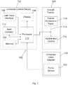
- the universal hitch adapter system may include the force sensor 102, as well as, a universal control device 700 communicatively coupled to the force sensor 102.
- the force sensor 102 and the universal control device 700 are connected via a wired connection (e.g., conductor, cable, wiring, etc.).
- the force sensor 102 and the universal control device 700 are connected via a wireless connection.
- the universal control device 700 may be a hand-held device shaped to be portably used by the tractor driver/user.
- An exemplary embodiment of a handheld universal control device 700 is illustrated in FIG. 8 .
- the universal control device 700 may be formed as a control panel installed within a dashboard associated with the aircraft tractor 500.
- the universal control device 700 may include at least one input 702 (e.g., i/o port) operable to receive force measurements from the force sensor 102.
- Conductors/wires communicatively coupling the force sensor 102 to the universal control device 700 may be routed internally through the aircraft tractor 500 to the dashboard. In other words, the wiring may extend from the hitch area of the aircraft tractor 500 to the dashboard area in which the universal control device 700 may be disposed.
- the universal control device 700 may include a memory 704, a user input interface 706, a display 708, at least one processor 710, and an alert indicator 712.
- the universal control device 700 may include additional features, or exclude some of the listed features.
- the alert indicator 712 may be provided as a separate device and may be disposed in an area outside of the dashboard area of the aircraft tractor 500.
- the memory 704 is a non-transitory memory operable to store a plurality of aircrafts thereon.
- the plurality of aircrafts may be stored on the non-transitory memory 704 so as to allow the driver to readily select one of the aircrafts that he/she is preparing to tow.
- the plurality of aircrafts may be stored on the memory 704 as the aircraft's commercial name, or some other representation, such as an alphanumeric code.
- the aircrafts are stored in the memory 704 so that the aircrafts can be displayed on the display 708 as an easily recognizable name (e.g., CRJ700) for the driver to readily identify and select.
- an easily recognizable name e.g., CRJ700
- the inventive universal control device and hitch adapter system allows an unskilled driver to receive audible and/or visual alerts responsive to a sheer pin breaking force threshold determined/calculated by the universal control device 700 according to the particular aircraft selected at any given time. This elegant solution can greatly increase the efficiency, costs, and safety associated with air travel.
- the user input interface 706 may be operable to receive a user's selection of one of the plurality of aircrafts stored in the memory 704.
- the user input interface 706 can include a keypad, a pointing device, a keyboard, a mouse, and/or the like.
- the user input interface 706 can be any device(s) that allow the user to enter input commands into the universal control device 700.
- the user input interface 706 is a touchscreen associated with the display 708 of the universal control device 700 and there can be icons or buttons displayed on the touchscreen that the user can engage/depress/tap in order to select one of the plurality of aircrafts that are presented to the user.
- Exemplary buttons or icons associated with the user input interface 706 may include an on/off button for the audible portion of an alert, an on/off button for activating an auto force feature, scrolling up/down buttons, power on, power off, backlight intensity adjustment buttons, a back button for the menu, a menu button to bring up the menu on the display 708, a data download button for downloading data (e.g., force measurements), etc.
- all of the force measurement data may be stored in the non-transitory memory 704 and downloadable via a data download output port (e.g., USB connection).
- the user may be provided with an option to input a shear pin breaking force threshold.
- the processor 710 may receive the user input parameter and may be operable to emit an alert as a result of the user-input threshold.
- the plurality of aircrafts can be presented on the display 708 in addition to any other information (e.g., shear pin breaking force threshold parameters, indicators, alerts, other status, etc.).
- the display 708 can be any type of suitable display, such as a liquid-crystal display (LCD), a plasma display, a light-emitting diode (LED) display, or the like, that may be used to present various images, text, graphics, and/or videos to the user.
- LCD liquid-crystal display
- LED light-emitting diode
- the processor 710 can be, for example, a central processing unit (CPU), a microcontroller, or a microprocessing device, including a "general purpose” microprocessing device or a special purpose microprocessing device.
- the processor 710 executes code stored in a memory, such as, for example, the memory 704 in order to carry out operation/instructions of the universal control device 700.
- the processor 710 may provide the processing capability to execute an operating system, run various applications, and provide processing for one or more of the techniques described herein.
- the processor 710 is communicatively coupled to the input 702, the memory 704, and the user input interface 706 and is operably configured to determine, based on the user's selection of one of the plurality of aircrafts, at least one shear pin breaking force threshold value.
- the maximum shear pin breaking force threshold for the shear pin associated with the aircraft may be pre-stored in the memory 704, as the specifications for these shear pins are generally pre-determined by the manufacturer of the shear pins.
- the processor 710 may determine a plurality of shear pin breaking force threshold values based on the maximum shear pin breaking force threshold provided by the manufacturer.
- the maximum shear pin breaking force threshold value for a shear pin associated with the CRJ-7 aircraft is 5,440 lbs.
- the processor 710 may be configured to output, for example, a yellow alert for force measurements within 10% of the maximum threshold, a red alert for force measurements within 5% of the maximum threshold, and a green alert status for any other force measurements received from the force sensor 102. It should be understood that there are a variety of different threshold determinations/alerts that the processor 710 may be configured with.
- the alert indicator 712 can be formed as a speaker, providing, an audio alert. In another embodiment, the alert indicator 712 can also be a visual alert (e.g., LED, lighting element, flashing icon on the display 708, etc.). Preferably, the alert indicator 712 includes both a visual and an audible alert aspect to provide maximum indication of the potential safety/damage issue.
- the alert indicator 712 may be communicatively coupled to the processor 710 and operably configured to emit an alert as a result of the force sensor 102 measuring a force transmitted on an aircraft towbar 606 coupled to the aircraft tractor hitch 600 ( FIG. 6 ) that meets or exceeds the shear pin breaking force threshold value. In one embodiment, the processor 710 and the alert indicator 712 are both integrated into the aircraft tractor 500.
- the processor 710 may automatically prevent acceleration of the aircraft tractor 500 if the force measurements from the force sensor 102 meet or exceed a critical threshold value or range (e.g., 1% of the maximum breaking force threshold value), the processor 710 may automatically prevent acceleration of the aircraft tractor 500.
- the processor 710 may be communicatively coupled to an electronic control line 714 for the aircraft tractor's accelerator control 716.
- the accelerator control 716 may be coupled to an accelerator pedal 718. Accordingly, in one embodiment, the processor 710 may be operable to automatically prevent acceleration of the aircraft tractor 500, via the electronic control line 714, as a result of the force sensor 102 measuring a force that meets or exceeds the shear pin breaking force threshold.
- the universal control device 700 may be operably configured and disposed to prevent acceleration signals from the accelerator pedal 718 from reaching the accelerator control 716.
- the processor 710 may be operable to automatically prevent acceleration of the aircraft tractor 500, via the electronic control line 714, as a result of the force sensor 102 sensing an aircraft load without the processor 710 having received the user's selection of one of the plurality of aircrafts.
- the universal control device 700 may be operably configured to force tractor driver's to select an aircraft so that the threshold value can be determined before the aircraft tractor 500 can be safely accelerated while towing an aircraft. If an aircraft load is not detected, the universal control device 700 may be operable to freely permit driver acceleration.
- FIG. 9 shows a specific order of executing the process steps, the order of executing the steps may be changed relative to the order shown in certain embodiments. Also, two or more blocks shown in succession may be executed concurrently or with partial concurrence in some embodiments. Certain steps may also be omitted in FIG. 9 for the sake of brevity. In some embodiments, some or all of the process steps included in FIG. 9 can be combined into a single process step.
- the process may begin at step 900 and may immediately proceed to step 902, where the force sensor 102 disposed at the aircraft tractor hitch area may continuously measure push-and-pull forces transmitted on the aircraft towbar 606.
- the aircraft tractor driver (or passenger or other associated airport employee/contractor) may couple the aircraft towbar 606 to the hitch 600. More particularly, the driver may slide the hitch pin 602 through an aperture defined by the towbar coupler 604 and secure the hitch pin 602.
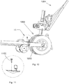
- the driver may also couple a towbar head 1000 of the aircraft towbar 606 to a nose gear 1002 of an aircraft 1004 according to known methods and apparatuses.
- the driver may secure the towbar head 1000 to the nose gear 1002 by coupling a shear pin 1100 to the towbar head 1000.
- the shear pin 1100 may slide through an aperture defined by a portion of the towbar head 1000. It is this shear pin 1100 that embodiments of the present invention are particularly configured to prevent breakage of.
- an aircraft tractor hitch 1300 may be formed as a multi-level hitch.
- the universal hitch adapter 100 may include more than one force sensor 102.
- the universal hitch adapter 100 may include two force sensors 102a-b to detect multi-level push-and-pull forces. Such multi-level hitches are sometimes used to tow particularly large aircrafts.
- the force sensor 102 may provide a force sensor output, i.e., force measurements, to the processor 710.
- the force sensor 102 may continuously provide force sensor outputs to the processor 710 for continuously monitoring for potential breakage conditions (e.g., force measurements exceeding or meeting the threshold values).
- the processor 710 may receive a user's (e.g., driver's) selection of one of the plurality of aircrafts stored in the memory 704. In step 908, the processor 710 may determine at least one shear pin breaking force threshold associated with the user-selected aircraft. In one embodiment, the processor 710 may retrieve from the memory 704 a pre-stored/pre-determined shear pin breaking force threshold stored in the memory 704 and associated in the memory 704 with the user-selected aircraft.
- the alert indicator 712 automatically provides an alert (audible and/or visual) as a result of the force sensor 102 measuring a force that meets or exceeds the shear pin breaking force threshold.
- the processor 710 may revise (determine another) the shear pin breaking force threshold based on the user's second selection of a second one of the plurality of aircrafts stored in the memory 704. The first aircraft may be considered different from the second aircraft. Accordingly, when the driver is ready to couple the aircraft tractor 500 to another aircraft for towing purposes, the driver need merely select another aircraft that he is preparing to tow. This allows the aircraft tractor 500 to safely tow a multitude of different aircrafts without breaking or wearing down the shear pin in an efficient and easily accessible manner and without requiring the driver to self-monitor such safety conditions.
- Embodiments of the invention provide a force sensor coupled to an aircraft tractor hitch that transmits push-and-pull force measurements to a universal hitch adapter control panel.
- the universal hitch adapter control panel include a memory storing a plurality of aircrafts thereon and a user input interface that allows a user (e.g., an aircraft tractor driver) to select one of the plurality of aircrafts that he/she is currently preparing to tow.
- the universal hitch adapter control panel may also include a processor that determines at least one sheer pin breaking force threshold based on the driver's selected aircraft. Additional embodiments of the present invention include an alarm that alerts the aircraft tractor driver as a result of the processor determining that a measured push-and-pull force from the force sensor has met or exceeded the sheer pin breaking force threshold determined by the processor.
Landscapes
- Engineering & Computer Science (AREA)
- Mechanical Engineering (AREA)
- Transportation (AREA)
- Aviation & Aerospace Engineering (AREA)
- Health & Medical Sciences (AREA)
- Public Health (AREA)
- Automation & Control Theory (AREA)
- Force Measurement Appropriate To Specific Purposes (AREA)
- Vehicle Body Suspensions (AREA)
Description
- This application claims priority to
U.S. Non-Provisional Patent Application No. 15/133,949 filed April 20, 2016 - The present invention relates generally to vehicle hitch adapters, and, more particularly, relates to a universal hitch adapter system for aircraft tractors to prevent nose gear shear pin failure on various aircrafts towed by such aircraft tractors.
- It is known that tractors are often used to tow aircraft on the ground from one location to another. Such tractors typically use a towbar with a coupler on one end and a towbar head on the other end. The coupler couples to the hitch of the tractor and the towbar head couples to a nose gear of the aircraft to be towed. Aircraft nose gears have a certain threshold force value that cannot be exceeded during the push and pull phase of a tractor maneuvering the towed aircraft on the ground. Exceeding this threshold force value can damage the nose gear/landing to the extent that it can malfunction after take-off, or render it unable to cycle correctly making it very dangerous for operation. If such damage to the nose gear is detected, the nose gear is required to be tested and certified prior to flight departure. This repair of the nose gear and testing for certification prior to any use in flight represents a significant monetary expense, including the time expended that the aircraft is unable for commercial use. If the damage to the nose gear goes undetected, it can result in serious problems during flight/take-off/landing that could, unfortunately, result in a crash or other dangerous situations. Accordingly, it is very important for aircraft tractors to tow aircrafts without exerting forces that would damage or wear away at the nose gear or nose gear shear pins. Unfortunately, prior art methods and devices are lacking.
- Use of aircraft tractors to move aircrafts, rather than the aircraft's own engines, became desirable in order to save on fuel. Initially, tractor speeds during towing efforts had been previously restricted to very slow speeds (i.e., less than 10 miles/hour). It became desirable to increase such speeds, even for fully loaded aircrafts, to increase the viability of taxiing fully loaded aircrafts by tractor, rather than the aircraft's engine, for additional fuel saving. However, this would increase forces between the aircraft and the tractor, which could result in too much force being transmitted to the nose gear. In addition, such higher speeds would increase the risks associated with jack-knifing. Also, it was not desirable to leave the control over the aircraft solely in the hands of the tractor driver, who may not have been as skilled and responsible as a pilot.
- One solution was developed in Patent No.
4,113, 041 - In order to avoid costly damage to the nose gear by transmitting forces that are too high for the nose gear to sustain, it is also known to use a towing pin, also referred to as a shear pin, as a mechanical fuse so that such high forces can break the shear pin, rather than the nose gear. However, this solution is not perfect. In order to guarantee that a shear pin will break when the situation requires it, such as when the steering angle of the wheels on the nose gear is considerable, sheer pins are manufactured with a rather large safety margin, which leads to pins breaking frequently, and sometimes unnecessarily. In addition, even though breaking the shear pin breaks the connection between the aircraft and the towbar (and, thereby, the tractor), which terminates the application of excessive forces to the nose gear, it is nonetheless a hazard as the aircraft may not completely come to a rest immediately after the connection is terminated, and may continue to roll on its own momentum.
- One solution was developed in Patent No.
9,108,746 WO 89/03343 A1 independent claims 1, 8 and 15. - Unfortunately, these prior art devices and systems are specific to a particular aircraft. Such devices and systems are not adaptable and flexible so that a single instance of a device/system may be tied to the tractor and configured for interchangeable use, on-the-fly, with multiple aircrafts, multiple shear pins, and multiple towbars.
- In particular, towhead shear pins are fitted to an individual aircraft towhead and are manufactured so as to shear upon a predetermined force being met or exceeded. Such shearing of the shear pin is intended to be an alert to the tractor driver that a safe force has been exceeded and inspection, as well as, replacement of the shear pin is required. Accordingly, failure of the shear pin itself is undesirable.
- Therefore, a need exists to overcome the problems with the prior art as discussed above.
- The invention provides a universal hitch adapter and system that overcomes the hereinafore-mentioned disadvantages of the heretofore-known devices and methods of this general type and that prevents sheer pin failures.
- With the foregoing and other objects in view, there is provided, in accordance with the invention, an aircraft tractor including a front end and a rear end opposite the front end; an aircraft tractor hitch; and a universal hitch adapter system. In one embodiment, the universal hitch adapter system may include at least one force sensor disposed between one of the front end and the rear end and the aircraft tractor hitch; at least one input operable to receive force measurements from the force sensor; a memory storing a plurality of aircrafts thereon; a user input interface operable to receive a user's selection of one of the plurality of aircrafts stored in the memory; and processor communicatively coupled to the input, the memory, and the user input interface and operably configured to determine, based on the user's selection of one of the plurality of aircrafts, at least one sheer pin breaking force threshold.
- In accordance with another feature, an embodiment of the present invention further includes an indicator communicatively coupled to the processor and operably configured to emit an alert as a result of the force sensor measuring a force transmitted on an aircraft towbar coupled to the aircraft tractor hitch that meets or exceeds the shear pin breaking force threshold.
- In accordance with another feature, an embodiment of the present invention includes an accelerator pedal; and an electronic control line communicatively coupled to the accelerator pedal. Further, in accordance with one embodiment of the present invention, the processor is communicatively coupled to the electronic control line and the processor is further operable to automatically prevent acceleration of the aircraft tractor, via the electronic control line, as a result of the force sensor measuring a force that meets or exceeds the shear pin breaking force threshold.
- In accordance with yet another feature, an embodiment of the present invention includes an accelerator pedal; and an electronic control line communicatively coupled to the accelerator pedal. Further, in accordance with one embodiment of the present invention, the processor is communicatively coupled to the electronic control line and the processor is further operable to automatically prevent acceleration of the aircraft tractor, via the electronic control line, as a result of the force sensor sensing an aircraft load without the processor having received the user's selection of one of the plurality of aircrafts.
- In accordance with another feature of the present invention, the universal hitch adapter further includes a steel insert operably configured to support the force sensor, the steel insert including a first coupling member and a second coupling member opposite the first coupling member with the force sensor interposed therebetween; and the first coupling member is coupled to the front end of the aircraft tractor and the second coupling member is coupled to the aircraft tractor hitch.
- In accordance with another feature of the present invention, the steel insert is of a hardened steel material.
- In accordance with a further feature of the present invention, the steel insert further includes at least two parallel stress plates, each of the parallel stress plates defining an aperture through which the force sensor is disposed and each of the parallel stress plates is translatable relative to one another about the force sensor so as to impart push-and-pull forces from an aircraft towbar on force sensor.
- In accordance with another feature of the present invention, an embodiment includes a universal aircraft tractor hitch adapter system with at least one force sensor disposed between one of a front end and a rear end of an aircraft tractor and an aircraft tractor hitch; and a universal control device. In accordance with one embodiment, the universal control devices includes at least one input operable to receive force measurements from the force sensor; a memory storing a plurality of aircrafts thereon; a user input interface operable to receive a user's selection of one of the plurality of aircrafts stored in the memory; and at least one processor communicatively coupled to the input, the memory, and the user input interface and operably configured to determine, based on the user's selection of one of the plurality of aircrafts, at least one sheer pin breaking force threshold.
- In accordance with an additional feature of the present invention, the processor is operably configured to transmit an alert as a result of the force sensor measuring a force transmitted on an aircraft towbar coupled to the aircraft tractor hitch that meets or exceeds the shear pin breaking force threshold.
- In accordance with yet another feature of the present invention, an embodiment includes a steel insert operably configured to support the force sensor, the steel insert including a first coupling member and a second coupling member opposite the first coupling member with the force sensor interposed therebetween, the first coupling member coupled to the front end of the aircraft tractor and the second coupling member coupled to the aircraft tractor hitch.
- In accordance with yet another feature of the present invention, the processor is further operable to automatically prevent acceleration of the aircraft tractor as a result of the force sensor sensing an aircraft load without the processor having received the user's selection of one of the plurality of aircrafts.
- In accordance with the present invention, a method for an aircraft tractor to safely tow aircrafts includes steps of measuring, by a force sensor disposed between one of a front end and a rear end of an aircraft tractor and an aircraft tractor hitch coupled to an aircraft towbar, push-and-pull forces transmitted on the aircraft towbar; providing a force sensor output, by the force sensor, to at least one processor; and receiving, by the processor, a user's first selection of one of a plurality of aircrafts stored in a memory communicatively coupled to the processor. In additional embodiments, the method may further include steps of determining, by the processor, at least one shear pin breaking force threshold associated with the user's first selection of one of the plurality of aircrafts; and providing, by an indicator communicatively coupled to the processor, an alert as a result of the force sensor measuring a force that meets or exceeds the shear pin breaking force threshold.
- In accordance with another feature, an embodiment of the present invention also includes a step of integrating the processor and the indicator into an aircraft tractor.
- In accordance with yet another feature, an embodiment of the present invention includes steps of coupling a towbar head of the aircraft towbar to a nose gear of an aircraft; and coupling a shear pin to the towbar head.
- In accordance with a further feature of the present invention, an embodiment further includes a step of revising, by the processor, the shear pin breaking force threshold based on a user's second selection of a second one of the plurality of aircrafts, different from the user's first selection of one of the plurality of aircrafts.
- In accordance with another feature of the present invention, an embodiment further includes automatically preventing, by the processor, acceleration of an aircraft tractor on which the force sensor is disposed as a result of the force sensor measuring a force that meets or exceeds the shear pin breaking force threshold.
- In accordance with yet another feature of the present invention, an embodiment includes a step of receiving, by the processor, a shear pin breaking force threshold input by the user.
- Although the invention is illustrated and described herein as embodied in a universal hitch adapter and system, it is, nevertheless, not intended to be limited to the details shown because various modifications and structural changes may be made therein without departing from the spirit of the invention and within the scope and range of equivalents of the claims. Additionally, well-known elements of exemplary embodiments of the invention will not be described in detail or will be omitted so as not to obscure the relevant details of the invention.
- Other features that are considered as characteristic for the invention are set forth in the appended claims. As required, detailed embodiments of the present invention are disclosed herein; however, it is to be understood that the disclosed embodiments are merely exemplary of the invention, which can be embodied in various forms. Therefore, specific structural and functional details disclosed herein are not to be interpreted as limiting, but merely as a basis for the claims and as a representative basis for teaching one of ordinary skill in the art to variously employ the present invention in virtually any appropriately detailed structure. Further, the terms and phrases used herein are not intended to be limiting; but rather, to provide an understandable description of the invention. While the specification concludes with claims defining the features of the invention that are regarded as novel, it is believed that the invention will be better understood from a consideration of the following description in conjunction with the drawing figures, in which like reference numerals are carried forward. The figures of the drawings are not drawn to scale.
- Before the present invention is disclosed and described, it is to be understood that the terminology used herein is for the purpose of describing particular embodiments only and is not intended to be limiting. The terms "a" or "an," as used herein, are defined as one or more than one. The term "plurality," as used herein, is defined as two or more than two. The term "another," as used herein, is defined as at least a second or more. The terms "including" and/or "having," as used herein, are defined as comprising (i.e., open language). The term "coupled," as used herein, is defined as connected, although not necessarily directly, and not necessarily mechanically. The term "providing" is defined herein in its broadest sense, e.g., bringing/coming into physical existence, making available, and/or supplying to someone or something, in whole or in multiple parts at once or over a period of time.
- As used herein, the terms "about" or "approximately" apply to all numeric values, whether or not explicitly indicated. These terms generally refer to a range of numbers that one of skill in the art would consider equivalent to the recited values (i.e., having the same function or result). In many instances these terms may include numbers that are rounded to the nearest significant figure. In this document, the term "longitudinal" should be understood to mean in a direction corresponding to an elongated direction of the universal hitch adapter from end to an opposing end. The terms "program," "software application," and the like as used herein, are defined as a sequence of instructions designed for execution on a computer system. A "program," "computer program," or "software application" may include a subroutine, a function, a procedure, an object method, an object implementation, an executable application, an applet, a servlet, a source code, an object code, a shared library/dynamic load library and/or other sequence of instructions designed for execution on a computer system.
- The accompanying figures, where like reference numerals refer to identical or functionally similar elements throughout the separate views and which together with the detailed description below are incorporated in and form part of the specification, serve to further illustrate various embodiments and explain various principles and advantages all in accordance with the present invention.
-
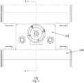
FIG. 1 is a perspective view of a universal hitch adapter in accordance with the present invention; -
FIG. 2 is a top plan view of the universal hitch adapter ofFIG. 1 in accordance with the present invention; -
FIG. 3 is a cross-sectional view of the universal hitch adapter ofFIG. 1 in accordance with the present invention; -
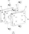
FIG. 4 is an exploded perspective view of the universal hitch adapter ofFIG. 1 in accordance with the present invention; -
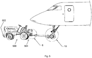
FIG. 5 is a side perspective view of the universal hitch adapter ofFIG. 1 coupled to the hitch of an aircraft tractor and towing an aircraft via an aircraft tractor towbar in accordance with the present invention; -
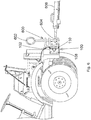
FIG. 6 is an enlarged view of the universal hitch adapter ofFIG. 1 coupled to the hitch introduced inFIG. 5 in accordance with an exemplary embodiment of the present invention; -
FIG. 7 is a block diagram view of a universal hitch adapter system in accordance with an exemplary embodiment of the present invention; -
FIG. 8 is a front perspective view of an exemplary universal control device in accordance with an embodiment of the present invention; -
FIG. 9 is an exemplary process in accordance with the present invention; -
FIG. 10 is an enlarged view of a towbar head and a shear pin coupled to the aircraft introduced inFIG. 5 in accordance with an exemplary embodiment of the present invention; -
FIG. 11 is an enlarged view of the towbar head and the shear pin depicted inFIG. 10 in accordance with an exemplary embodiment of the present invention; -
FIG. 12 a side perspective view of another embodiment of a universal hitch adapter coupled to a multi-level hitch of an aircraft tractor and towing a large aircraft via an aircraft tractor towbar in accordance with the present invention; -
FIG. 13 is an enlarged view of the multi-level hitch and the universal hitch adapter ofFIG. 12 in accordance with an embodiment of the present invention; and -
FIG. 14 is an enlarged view of a towbar head and a shear pin ofFIG. 12 in accordance with an exemplary embodiment of the present invention - While the specification concludes with claims defining the features of the invention that are regarded as novel, it is believed that the invention will be better understood from a consideration of the following description in conjunction with the drawing figures, in which like reference numerals are carried forward. It is to be understood that the disclosed embodiments are merely exemplary of the invention, which can be embodied in various forms.
- The present invention provides a novel and efficient universal aircraft tractor hitch adapter system. Embodiments of the invention provide a force sensor coupled to an aircraft tractor hitch that transmits push-and-pull force measurements to a universal hitch adapter control panel. In addition, embodiments of the invention provide that the universal hitch adapter control panel include a memory storing a plurality of aircrafts thereon and a user input interface that allows a user (e.g., an aircraft tractor driver) to select one of the plurality of aircrafts that he/she is currently preparing to tow. In embodiments of the present invention, the universal hitch adapter control panel may also include a processor that determines at least one sheer pin breaking force threshold based on the driver's selected aircraft. Additional embodiments of the present invention include an alarm that alerts the aircraft tractor driver as a result of the processor determining that a measured push-and-pull force from the force sensor has met or exceeded the sheer pin breaking force threshold determined by the processor.
- Referring now to
FIGS. 1-2 , one embodiment of the present invention is shown in a perspective view and a top plan view, respectively.FIGS. 1-2 show several advantageous features of the present invention, but, as will be described below, the invention can be provided in several shapes, sizes, combinations of features and components, and varying numbers and functions of the components. The first example of a universal aircrafttractor hitch adapter 100, as shown inFIGS. 1-2 , includes at least oneforce sensor 102. - In one embodiment, the
force sensor 102 is operable to measure tension and compression forces (also known in the art as "linear shear forces" and "push-and-pull forces"). In a preferred embodiment, theforce sensor 102 may be formed as a strain gauge transducer. In another embodiment, theforce sensor 102 may be formed as other types of force sensors, such as, for example, a piezoeletric transducer, a pneumatic load cell, and the like. Importantly, theforce sensor 102 is adapted to be able to withstand repeated and prolonged high-stress forces associated with pulling/towing large aircraft. Accordingly, in one embodiment, theforce sensor 102 may be made of a steel material (e.g., a hardened steel material). In another embodiment, theforce sensor 102 may be made of another hardened metallic material. In yet further embodiments, theforce sensor 102 may be made of another non-metallic rugged material suitable for transmitting repeated and continuous high-stress forces associating with towing aircraft. - In one embodiment, the
force sensor 102 is shaped as a pin or bolt. Advantageously, this shape of theforce sensor 102 allows theforce sensor 102 to be readily adapted and readily replaceable/interchangeable as a coupling member upon which linear shear forces may be applied. Stated another way, in the field of heavy-duty machinery, such as aircraft tractors, there are necessarily junctures at which high-stress operational forces are repeatedly and continuously applied and which are transmitted by pivoting pins, bolts, or other similar fasteners. According, these juncture points (e.g., hitch) would benefit from force monitoring in order to detect possible shear conditions. Providing theforce sensor 102 in the shape of a pin or bolt allows theforce sensor 102 to be readily adapted to be integrated into such juncture points. In an alternative embodiment, theforce sensor 102 may be formed as other shapes and sizes. - In one embodiment, the
force sensor 102 includes a plurality of pins 104 (or other conductors) operable to transmit sensor output (e.g., linear shear force measurements) to a receiving device such as, for example, a processor or other circuitry. In one embodiment, theforce sensor 102 may include 6 pins. In another embodiment, theforce sensor 102 may include more or less than 6 pins. In yet another embodiment, the plurality ofpins 104 may be provided in a connector shaped and configured to mate with a mating connector cable. - In one embodiment, the universal aircraft
tractor hitch adapter 100 further includes aninsert 106 operably configured to support theforce sensor 102. In one embodiment, theinsert 106 is disposed to transmit linear shear force measurements from an aircraft towbar (not shown) to theforce sensor 102. In a further embodiment, theinsert 106 may include afirst coupling member 108 and asecond coupling member 110 opposite thefirst coupling member 108. In one embodiment, theforce sensor 102 is interposed between thefirst coupling member 108 and thesecond coupling member 110. Each of thecoupling members plate member 200. In another embodiment, each of thecoupling members plate member 202. In one embodiment, theplate members plate members 202 for eachcoupling member plate members 202 may define anaperture 112 or bore through which at least a portion of theforce sensor 102 is disposed. In other words, the stress plates may be parallel with one another. In another embodiment, the horizontally orientedplate members 202 may be considered parallel stress plates. In one embodiment, theparallel stress plates 202 may be disposed translatable relative to one another about theforce sensor 102 so as to impart or transmit push-and-pull forces from an aircraft towbar on theforce sensor 102. Stated another way, therespective apertures 112 defined by eachplate member 202 may include a diameter slightly larger than a diameter of a portion of theforce sensor 102 disposed within theapertures 112. In other words, theplate members 202 may be configured to provide some give or translatability so that push-and-pull forces can be applied to theforce sensor 102 via theplate members 202. In other embodiments, thecoupling members - The
insert 106 may be made of a steel material adapted for withstanding repeated and prolonged high-stress forces associated with towing aircraft. In another embodiment, theinsert 106 may be made of a hardened steel material. Hardening the steel includes a relatively time-consuming process of heating the steel to very high temperatures. In order to harden the steel, the steel must typically include a relatively large amount of carbon. Hardening the steel will toughen theinsert 106 and render theinsert 106 less susceptible to wearing out over time; an aspect that is important to such heavy-duty aircraft applications. In yet another embodiment, theinsert 106 may be made of another hardened metallic material. In yet further embodiments, theinsert 106 may be made of another non-metallic rugged material suitable for transmitting repeated and continuous high-stress forces associating with towing aircraft. - Referring now to
FIG. 3 , the exemplary universal aircrafttractor hitch adapter 100 is shown in a cross-sectional view. In one embodiment, theforce sensor 102 may define alongitudinal axis 300 extending in an elongation direction of theforce sensor 102 from a top end to a bottom end thereof. Theforce sensor 102 may be configured to detect linear push-and-pullforces 302 perpendicular to thelongitudinal axis 300. In another embodiment, theforce sensor 102 may be configured to detect linear push-and-pull forces substantially perpendicular to the longitudinal axis 300 (90 degrees +/- 5%). - In one embodiment, the
force sensor 102 may include arim portion 304 that extends outwardly in a horizontal direction beyond aneck portion 306 of theforce sensor 102. In a further embodiment, theplate member 202 may include aledge portion 308 circumscribing a perimeter of theaperture 112. Therim portion 304 of theforce sensor 102 may be operably configured to rest on theledge portion 308. - Referring now to
FIG. 4 , the universal aircrafttractor hitch adapter 100 may includeadditional support plates support plates support plates support plates support plates support plates coupling members more fasteners 404 and may provide additional support to theuniversal hitch adapter 100. Thefasteners 404 may be formed as any type of rugged fastener suitable for heavy-duty aircraft applications, such as, for example, bolts. - Referring now to
FIGS. 5 and6 , aninventive aircraft tractor 500 is illustrated in a schematic view illustrating the universal aircrafttractor hitch adapter 100 installed on theaircraft tractor 500. Aircraft tractors are generally provided in one of two forms: 1) a traditional tractor with a hitch that uses a towbar to push/pull aircraft, and 2) a towbarless tractor. The towbarless tractor does not use a towbar, but rather scoops up the nose gear off the ground so that the nose gear rests on top of the tractor itself. Embodiments of the present invention are limited to the traditional tractor and are not designed for use with the towbarless tractor. Accordingly, theaircraft tractor 500 includes anaircraft tractor hitch 600. Theaircraft tractor hitch 600 may be disposed on afront end 502 or arear end 504 of theaircraft tractor 500. Thefront end 502 may be opposite therear end 504. The universalaircraft hitch adapter 100 may be disposed between one of thefront end 502 and therear end 504 and theaircraft tractor hitch 600. In the exemplary embodiment depicted inFIGS. 5 and6 , theforce sensor 102 is disposed between thefront end 502 and theaircraft tractor hitch 600. In an alternative embodiment, theforce sensor 102 may be disposed between therear end 504 and theaircraft tractor hitch 600. - In one embodiment, the
first coupling member 108 is coupled to thefront end 502 and the second coupling member is coupled to theaircraft tractor hitch 600. In an alternative embodiment, thefirst coupling member 108 may be coupled to therear end 504 and thesecond coupling member 110 may be coupled to theaircraft tractor hitch 600. Thecoupling members aircraft tractor 500 and hitch 600 in a multitude of ways, such as, for example, bolts, fasteners, adhesives, etc. Preferably, such fasteners/couplers are rugged and adapted to withstand repeated and continuous high-stress forces associating with towing aircraft. Theaircraft tractor hitch 600 may include ahitch pin 602 on which atowbar coupler 604 is slideably coupled to. - Referring now to
FIGS. 7 and8 , an exemplary universal hitch adapter system is illustrated in a block diagram view and a front perspective view, respectively. In one embodiment, the universal hitch adapter system may include theforce sensor 102, as well as, auniversal control device 700 communicatively coupled to theforce sensor 102. In one embodiment, theforce sensor 102 and theuniversal control device 700 are connected via a wired connection (e.g., conductor, cable, wiring, etc.). In another embodiment, theforce sensor 102 and theuniversal control device 700 are connected via a wireless connection. Theuniversal control device 700 may be a hand-held device shaped to be portably used by the tractor driver/user. An exemplary embodiment of a handhelduniversal control device 700 is illustrated inFIG. 8 . In another embodiment, theuniversal control device 700 may be formed as a control panel installed within a dashboard associated with theaircraft tractor 500. - In one embodiment, the
universal control device 700 may include at least one input 702 (e.g., i/o port) operable to receive force measurements from theforce sensor 102. Conductors/wires communicatively coupling theforce sensor 102 to theuniversal control device 700, in some embodiments, may be routed internally through theaircraft tractor 500 to the dashboard. In other words, the wiring may extend from the hitch area of theaircraft tractor 500 to the dashboard area in which theuniversal control device 700 may be disposed. - In one embodiment, the
universal control device 700 may include amemory 704, auser input interface 706, adisplay 708, at least oneprocessor 710, and analert indicator 712. In other embodiments, theuniversal control device 700 may include additional features, or exclude some of the listed features. For example, in one embodiment, thealert indicator 712 may be provided as a separate device and may be disposed in an area outside of the dashboard area of theaircraft tractor 500. - In one embodiment, the
memory 704 is a non-transitory memory operable to store a plurality of aircrafts thereon. The plurality of aircrafts may be stored on thenon-transitory memory 704 so as to allow the driver to readily select one of the aircrafts that he/she is preparing to tow. The plurality of aircrafts may be stored on thememory 704 as the aircraft's commercial name, or some other representation, such as an alphanumeric code. Preferably, the aircrafts are stored in thememory 704 so that the aircrafts can be displayed on thedisplay 708 as an easily recognizable name (e.g., CRJ700) for the driver to readily identify and select. Advantageously, by providing a menu of pre-stored aircraft names/indicators that the user may be able to scroll through, for example, and select, aircraft tractor drivers, who sometimes have limited training and skill, can safely tow expensive aircrafts without damaging the shear pin and/or nose gears. As will be described in more detail herein below, the inventive universal control device and hitch adapter system allows an unskilled driver to receive audible and/or visual alerts responsive to a sheer pin breaking force threshold determined/calculated by theuniversal control device 700 according to the particular aircraft selected at any given time. This elegant solution can greatly increase the efficiency, costs, and safety associated with air travel. - The
user input interface 706 may be operable to receive a user's selection of one of the plurality of aircrafts stored in thememory 704. Theuser input interface 706 can include a keypad, a pointing device, a keyboard, a mouse, and/or the like. Theuser input interface 706 can be any device(s) that allow the user to enter input commands into theuniversal control device 700. In one embodiment, theuser input interface 706 is a touchscreen associated with thedisplay 708 of theuniversal control device 700 and there can be icons or buttons displayed on the touchscreen that the user can engage/depress/tap in order to select one of the plurality of aircrafts that are presented to the user. Exemplary buttons or icons associated with theuser input interface 706 may include an on/off button for the audible portion of an alert, an on/off button for activating an auto force feature, scrolling up/down buttons, power on, power off, backlight intensity adjustment buttons, a back button for the menu, a menu button to bring up the menu on thedisplay 708, a data download button for downloading data (e.g., force measurements), etc. In one embodiment, all of the force measurement data may be stored in thenon-transitory memory 704 and downloadable via a data download output port (e.g., USB connection). In one embodiment, where, for example, the aircraft being towed is not pre-stored/pre-determined in thememory 704, the user may be provided with an option to input a shear pin breaking force threshold. Theprocessor 710 may receive the user input parameter and may be operable to emit an alert as a result of the user-input threshold. - The plurality of aircrafts can be presented on the
display 708 in addition to any other information (e.g., shear pin breaking force threshold parameters, indicators, alerts, other status, etc.). Thedisplay 708 can be any type of suitable display, such as a liquid-crystal display (LCD), a plasma display, a light-emitting diode (LED) display, or the like, that may be used to present various images, text, graphics, and/or videos to the user. - The
processor 710 can be, for example, a central processing unit (CPU), a microcontroller, or a microprocessing device, including a "general purpose" microprocessing device or a special purpose microprocessing device. Theprocessor 710 executes code stored in a memory, such as, for example, thememory 704 in order to carry out operation/instructions of theuniversal control device 700. Theprocessor 710 may provide the processing capability to execute an operating system, run various applications, and provide processing for one or more of the techniques described herein. - In one embodiment, the
processor 710 is communicatively coupled to theinput 702, thememory 704, and theuser input interface 706 and is operably configured to determine, based on the user's selection of one of the plurality of aircrafts, at least one shear pin breaking force threshold value. In one embodiment, the maximum shear pin breaking force threshold for the shear pin associated with the aircraft may be pre-stored in thememory 704, as the specifications for these shear pins are generally pre-determined by the manufacturer of the shear pins. In one embodiment, theprocessor 710 may determine a plurality of shear pin breaking force threshold values based on the maximum shear pin breaking force threshold provided by the manufacturer. For example, the maximum shear pin breaking force threshold value for a shear pin associated with the CRJ-7 aircraft is 5,440 lbs. Accordingly, theprocessor 710 may be configured to output, for example, a yellow alert for force measurements within 10% of the maximum threshold, a red alert for force measurements within 5% of the maximum threshold, and a green alert status for any other force measurements received from theforce sensor 102. It should be understood that there are a variety of different threshold determinations/alerts that theprocessor 710 may be configured with. - The
alert indicator 712 can be formed as a speaker, providing, an audio alert. In another embodiment, thealert indicator 712 can also be a visual alert (e.g., LED, lighting element, flashing icon on thedisplay 708, etc.). Preferably, thealert indicator 712 includes both a visual and an audible alert aspect to provide maximum indication of the potential safety/damage issue. Thealert indicator 712 may be communicatively coupled to theprocessor 710 and operably configured to emit an alert as a result of theforce sensor 102 measuring a force transmitted on anaircraft towbar 606 coupled to the aircraft tractor hitch 600 (FIG. 6 ) that meets or exceeds the shear pin breaking force threshold value. In one embodiment, theprocessor 710 and thealert indicator 712 are both integrated into theaircraft tractor 500. - In one embodiment, if the force measurements from the
force sensor 102 meet or exceed a critical threshold value or range (e.g., 1% of the maximum breaking force threshold value), theprocessor 710 may automatically prevent acceleration of theaircraft tractor 500. In one embodiment, theprocessor 710 may be communicatively coupled to an electronic control line 714 for the aircraft tractor'saccelerator control 716. Theaccelerator control 716 may be coupled to anaccelerator pedal 718. Accordingly, in one embodiment, theprocessor 710 may be operable to automatically prevent acceleration of theaircraft tractor 500, via the electronic control line 714, as a result of theforce sensor 102 measuring a force that meets or exceeds the shear pin breaking force threshold. In a further embodiment, theuniversal control device 700 may be operably configured and disposed to prevent acceleration signals from theaccelerator pedal 718 from reaching theaccelerator control 716. In another embodiment, theprocessor 710 may be operable to automatically prevent acceleration of theaircraft tractor 500, via the electronic control line 714, as a result of theforce sensor 102 sensing an aircraft load without theprocessor 710 having received the user's selection of one of the plurality of aircrafts. In other words, theuniversal control device 700 may be operably configured to force tractor driver's to select an aircraft so that the threshold value can be determined before theaircraft tractor 500 can be safely accelerated while towing an aircraft. If an aircraft load is not detected, theuniversal control device 700 may be operable to freely permit driver acceleration. - An exemplary process for an aircraft tractor to safely tow aircrafts in accordance with the present invention will be described in conjunction with the process flow chart of
FIG. 9 , with reference toFIGS. 6-7 and10-14 . AlthoughFIG. 9 shows a specific order of executing the process steps, the order of executing the steps may be changed relative to the order shown in certain embodiments. Also, two or more blocks shown in succession may be executed concurrently or with partial concurrence in some embodiments. Certain steps may also be omitted inFIG. 9 for the sake of brevity. In some embodiments, some or all of the process steps included inFIG. 9 can be combined into a single process step. - The process may begin at
step 900 and may immediately proceed to step 902, where theforce sensor 102 disposed at the aircraft tractor hitch area may continuously measure push-and-pull forces transmitted on theaircraft towbar 606. In one embodiment, prior to step 902, the aircraft tractor driver (or passenger or other associated airport employee/contractor) may couple theaircraft towbar 606 to thehitch 600. More particularly, the driver may slide thehitch pin 602 through an aperture defined by thetowbar coupler 604 and secure thehitch pin 602. In addition, the driver may also couple atowbar head 1000 of theaircraft towbar 606 to anose gear 1002 of anaircraft 1004 according to known methods and apparatuses. The driver may secure thetowbar head 1000 to thenose gear 1002 by coupling ashear pin 1100 to thetowbar head 1000. In one embodiment, theshear pin 1100 may slide through an aperture defined by a portion of thetowbar head 1000. It is thisshear pin 1100 that embodiments of the present invention are particularly configured to prevent breakage of. - In an alternative embodiment of the
inventive aircraft tractor 500, anaircraft tractor hitch 1300 may be formed as a multi-level hitch. In such an embodiment, theuniversal hitch adapter 100 may include more than oneforce sensor 102. For example, theuniversal hitch adapter 100 may include two force sensors 102a-b to detect multi-level push-and-pull forces. Such multi-level hitches are sometimes used to tow particularly large aircrafts. - In
step 902, theforce sensor 102 may provide a force sensor output, i.e., force measurements, to theprocessor 710. In one embodiment, theforce sensor 102 may continuously provide force sensor outputs to theprocessor 710 for continuously monitoring for potential breakage conditions (e.g., force measurements exceeding or meeting the threshold values). - In
step 906, theprocessor 710 may receive a user's (e.g., driver's) selection of one of the plurality of aircrafts stored in thememory 704. Instep 908, theprocessor 710 may determine at least one shear pin breaking force threshold associated with the user-selected aircraft. In one embodiment, theprocessor 710 may retrieve from the memory 704 a pre-stored/pre-determined shear pin breaking force threshold stored in thememory 704 and associated in thememory 704 with the user-selected aircraft. - In one embodiment, the
alert indicator 712 automatically provides an alert (audible and/or visual) as a result of theforce sensor 102 measuring a force that meets or exceeds the shear pin breaking force threshold. In a further embodiment, theprocessor 710 may revise (determine another) the shear pin breaking force threshold based on the user's second selection of a second one of the plurality of aircrafts stored in thememory 704. The first aircraft may be considered different from the second aircraft. Accordingly, when the driver is ready to couple theaircraft tractor 500 to another aircraft for towing purposes, the driver need merely select another aircraft that he is preparing to tow. This allows theaircraft tractor 500 to safely tow a multitude of different aircrafts without breaking or wearing down the shear pin in an efficient and easily accessible manner and without requiring the driver to self-monitor such safety conditions. - A novel and efficient universal aircraft tractor hitch adapter system has been disclosed that greatly increases air travel safety, increases aircraft towing efficiency, and decreases costs associated with shear pin and nose gear breakage/malfunctions. Embodiments of the invention provide a force sensor coupled to an aircraft tractor hitch that transmits push-and-pull force measurements to a universal hitch adapter control panel. In addition, embodiments of the invention provide that the universal hitch adapter control panel include a memory storing a plurality of aircrafts thereon and a user input interface that allows a user (e.g., an aircraft tractor driver) to select one of the plurality of aircrafts that he/she is currently preparing to tow. In embodiments of the present invention, the universal hitch adapter control panel may also include a processor that determines at least one sheer pin breaking force threshold based on the driver's selected aircraft. Additional embodiments of the present invention include an alarm that alerts the aircraft tractor driver as a result of the processor determining that a measured push-and-pull force from the force sensor has met or exceeded the sheer pin breaking force threshold determined by the processor.
Claims (20)
- An aircraft tractor (500) comprising:a front end (502) and a rear end (504) opposite the front end (502);an aircraft tractor hitch (600); anda universal hitch adapter system including:at least one force sensor (102) disposed between one of the front end (502) and the rear end (504) and the aircraft tractor hitch (600); andat least one input (702) operable to receive force measurements from the at least one force sensor (102);characterized by further including:a memory (704) storing a plurality of aircraft thereon;a user input interface (706) operable to receive a user's selection of one of the plurality of aircraft stored in the memory (704); andat least one processor (710) communicatively coupled to the at least one input (702), the memory (704), and the user input interface (706) and operably configured to determine, based on the user's selection of one of the plurality of aircraft, at least one shear pin breaking force threshold.
- The aircraft tractor (500) in accordance with claim 1, further comprising:
an indicator (712) communicatively coupled to the at least one processor (710) and operably configured to emit an alert as a result of the at least one force sensor (102) measuring a force transmitted on an aircraft towbar (606) coupled to the aircraft tractor hitch (600) that meets or exceeds the at least one shear pin breaking force threshold. - The aircraft tractor (500) in accordance with claim 1, further comprising:an accelerator pedal (718); andan electronic control line (714) communicatively coupled to the accelerator pedal (718); andwherein the at least one processor (710) is communicatively coupled to the electronic control line (714) and the at least one processor (710) is further operable to automatically prevent acceleration of the aircraft tractor (500), via the electronic control line (714), as a result of the at least one force sensor (102) measuring a force that meets or exceeds the at least one shear pin breaking force threshold.
- The aircraft tractor (500) in accordance with claim 1, further comprising:an accelerator pedal (718); andan electronic control line (714) communicatively coupled to the accelerator pedal (718); andwherein the at least one processor (710) is communicatively coupled to the electronic control line (714) and the at least one processor (710) is further operable to automatically prevent acceleration of the aircraft tractor (500), via the electronic control line (714), as a result of the at least one force sensor (102) sensing an aircraft load without the at least one processor (710) having received the user's selection of one of the plurality of aircraft.
- The aircraft tractor (500) in accordance with claim 1, wherein:the universal hitch adapter (100) further includes a steel insert (106) operably configured to support the at least one force sensor (102), the steel insert (106) including a first coupling member (108) and a second coupling member (110) opposite the first coupling member (108) with the at least one force sensor (102) interposed therebetween; andthe first coupling member (108) is coupled to the front end (502) of the aircraft tractor (500) and the second coupling member (110) is coupled to the aircraft tractor hitch (600).
- The aircraft tractor (500) in accordance with claim 5, wherein:
the steel insert (106) is of a hardened steel material. - The aircraft tractor (500) in accordance with claim 5, wherein:
the steel insert (106) further comprises at least two parallel stress plates (202), each of the at least two parallel stress plates (202) defining an aperture through which the at least one force sensor (102) is disposed and each of the at least two parallel stress plates (202) translatable relative to one another about the at least one force sensor (102) so as to impart push-and-pull forces from an aircraft towbar (606) on the at least one force sensor (102). - A universal aircraft tractor hitch adapter system comprising:at least one force sensor (102) disposed between one of a front end (502) and a rear end (504) of an aircraft tractor (500) and an aircraft tractor hitch (600); anda universal control device (700) including:at least one input (702) operable to receive force measurements fromthe at least one force sensor (102)characterized by further including:a memory (704) storing a plurality of aircraft thereon;a user input interface (706) operable to receive a user's selection of one of the plurality of aircraft stored in the memory (704); andat least one processor (710) communicatively coupled to the at least one input (702), the memory (704), and the user input interface (706) and operably configured to determine, based on the user's selection of one of the plurality of aircraft, at least one shear pin breaking force threshold.
- The universal aircraft tractor hitch adapter system in accordance with claim 8, wherein:
the at least one processor (710) is operably configured to transmit an alert as a result of the at least one force sensor (102) measuring a force transmitted on an aircraft towbar (606) coupled to the aircraft tractor hitch (600) that meets or exceeds the at least one shear pin breaking force threshold. - The universal aircraft tractor hitch adapter system in accordance with claim 9, further comprising:
a steel insert (106) operably configured to support the at least one force sensor (102), the steel insert (106) including a first coupling member (108) and a second coupling member (110) opposite the first coupling member (108) with the at least one force sensor (102) interposed therebetween, the first coupling member (108) coupled to the front end (502) of the aircraft tractor (500) and the second coupling member (110) coupled to the aircraft tractor hitch (600). - The universal aircraft tractor hitch adapter system in accordance with claim 10, wherein:
the steel insert (106) further comprises at least two parallel stress plates (202), each of the at least two parallel stress plates (202) defining an aperture (112) through which the at least one force sensor (102) is disposed and each of the at least two parallel stress plates (202) translatable relative to one another about the at least one force
sensor (102) so as to impart push-and-pull forces from the aircraft towbar (606) on the at least one force sensor (102). - The universal aircraft tractor hitch adapter system in accordance with claim 11, wherein:
the steel insert (106) is of a hardened steel material. - The universal aircraft tractor hitch adapter system in accordance with claim 9. wherein:
the at least one processor (710) is communicatively coupled to an electronic control line (714) for an accelerator pedal (718) of the aircraft tractor (500) and the at least one processor (710) is further operable to automatically prevent acceleration of the aircraft tractor (500), via the electronic control line (714), as a result of the at least one force sensor (102) measuring a force that meets at or exceeds the at least one shear pin breaking force threshold. - The universal aircraft tractor hitch adapter system in accordance with claim 9, wherein:
the at least one processor (710) is further operable to automatically prevent acceleration of the aircraft tractor (500) as a result of the at least one force sensor (102) sensing an aircraft load without the at least one processor (710) having received the user's selection of one of the plurality of aircraft. - A method for an aircraft tractor (500) to safely tow aircraft, the method comprising steps of:measuring, by a force sensor (102) disposed between one of a front end (502) and a rear end (504) of an aircraft tractor (500) and an aircraft tractor hitch (600) coupled to an aircraft towbar (606), push-and-pull forces transmitted on the aircraft towbar (606);providing a force sensor output, by the force sensor (102), to at least oneprocessor (710)characterized by the following steps:receiving, by the at least one processor (710), a user's first selection of one of a plurality of aircraft stored in a memory (704) communicatively coupled to the at least one processor (710);determining, by the at least one processor (710), at least one shear pin breaking force threshold associated with the user's first selection of one of the plurality of aircraft; andproviding, by an indicator (712) communicatively coupled to the at least one processor (710), an alert as a result of the force sensor (102) measuring a force that meets or exceeds the at least one shear pin breaking force threshold.
- The method in accordance with claim 15, further comprising a step of:
integrating the at least one processor (710) and the indicator (712) into an aircraft tractor (500). - The method in accordance with claim 15, further comprising steps of:coupling a towbar head (1000) of the aircraft towbar (606) to a nose gear (1002) of an aircraft; andcoupling a shear pin (1100) to the towbar head (1000).
- The method in accordance with claim 15, further comprising:
revising, by the at least one processor (710), the at least one shear pin breaking force threshold based on a user's second selection of a second one of the plurality of aircraft, different from the user's first selection of one of the plurality of aircraft. - The method in accordance with claim 15, further comprising a step of:
automatically preventing, by the at least one processor (710), acceleration of an aircraft tractor (500) on which the force sensor (102) is disposed as a result of the force sensor (102) measuring a force that meets or exceeds the at least one shear pin breaking force threshold. - The method in accordance with claim 15, further comprising a step of:
receiving, by the at least one processor (710), a shear pin breaking force threshold input by the user.
Applications Claiming Priority (2)
| Application Number | Priority Date | Filing Date | Title |
|---|---|---|---|
| US15/133,949 US10166826B2 (en) | 2016-04-20 | 2016-04-20 | Universal hitch adapter and system |
| PCT/US2017/028309 WO2017184699A1 (en) | 2016-04-20 | 2017-04-19 | Universal hitch adapter and system |
Publications (2)
| Publication Number | Publication Date |
|---|---|
| EP3445656A1 EP3445656A1 (en) | 2019-02-27 |
| EP3445656B1 true EP3445656B1 (en) | 2021-01-06 |
Family
ID=58668955
Family Applications (1)
| Application Number | Title | Priority Date | Filing Date |
|---|---|---|---|
| EP17721238.8A Active EP3445656B1 (en) | 2016-04-20 | 2017-04-19 | Universal hitch adapter and system |
Country Status (6)
| Country | Link |
|---|---|
| US (1) | US10166826B2 (en) |
| EP (1) | EP3445656B1 (en) |
| CN (1) | CN109311540B (en) |
| DK (1) | DK3445656T3 (en) |
| ES (1) | ES2857024T3 (en) |
| WO (1) | WO2017184699A1 (en) |
Families Citing this family (16)
| Publication number | Priority date | Publication date | Assignee | Title |
|---|---|---|---|---|
| US10147246B2 (en) * | 2016-06-09 | 2018-12-04 | Magna Electronics Inc. | Wheel bolt torque monitoring system for vehicle |
| EP3379222B1 (en) | 2017-03-22 | 2020-12-30 | Methode Electronics Malta Ltd. | Magnetoelastic based sensor assembly |
| DE18907724T1 (en) | 2018-02-27 | 2021-03-25 | Methode Electronics, Inc. | Towing systems and methods using magnetic field measurement |
| US11491832B2 (en) | 2018-02-27 | 2022-11-08 | Methode Electronics, Inc. | Towing systems and methods using magnetic field sensing |
| US11135882B2 (en) | 2018-02-27 | 2021-10-05 | Methode Electronics, Inc. | Towing systems and methods using magnetic field sensing |
| US11221262B2 (en) | 2018-02-27 | 2022-01-11 | Methode Electronics, Inc. | Towing systems and methods using magnetic field sensing |
| US11084342B2 (en) | 2018-02-27 | 2021-08-10 | Methode Electronics, Inc. | Towing systems and methods using magnetic field sensing |
| US11014417B2 (en) | 2018-02-27 | 2021-05-25 | Methode Electronics, Inc. | Towing systems and methods using magnetic field sensing |
| DE102018114874B4 (en) * | 2018-06-20 | 2022-02-03 | JMS AG Jet Maintenance & Service | Tow bar with measuring device and method of its operation |
| US11964777B2 (en) * | 2020-09-29 | 2024-04-23 | Safran Landing Systems Canada Inc. | Remote aircraft towing interface |
| CN113484877B (en) * | 2021-07-14 | 2024-02-13 | 中国东方航空股份有限公司 | Method and system for collision avoidance of aircraft on the ground |
| CN113998135B (en) * | 2021-10-18 | 2023-11-28 | 上海机电工程研究所 | Axial locking and releasing assembly for fracture-resistant unmanned aerial vehicle |
| US20230131387A1 (en) * | 2021-10-26 | 2023-04-27 | GM Global Technology Operations LLC | Tow management systems and methods for autonomous vehicles |
| CN116280233B (en) * | 2022-09-07 | 2026-01-02 | 厦门航空有限公司 | Aircraft main landing gear alarm methods, devices, computer equipment, and storage media |
| CA3214901A1 (en) * | 2022-11-15 | 2024-05-15 | Goodrich Corporation | Smart aircraft towing system |
| US12260767B2 (en) * | 2022-11-15 | 2025-03-25 | Goodrich Corporation | Smart aircraft towing system |
Family Cites Families (26)
| Publication number | Priority date | Publication date | Assignee | Title |
|---|---|---|---|---|
| GB1459027A (en) | 1974-04-26 | 1976-12-22 | Strainstall Ltd | Mooring device |
| SE411736B (en) | 1974-06-15 | 1980-02-04 | Birkeholm Mogens | PROCEDURE AND DEVICE FOR TOWING A VEHICLE, EXAMPLE OF AN AIRPLANE |
| DE3732645C1 (en) | 1987-09-28 | 1988-09-29 | Krauss Maffei Ag | Aircraft towing vehicle - hold-down system |
| SE459413B (en) | 1987-10-14 | 1989-07-03 | Birkeholm Mogens | SEATS TO PREVENT OVERLOADING OF AN AIRPLANE NOS WHEEL STEEL DURING TOWING WITH TRACTOR AND TRACTOR BEFORE EXERCISE OF THE SEAT |
| GB8805133D0 (en) * | 1988-03-03 | 1988-03-30 | Soil Machine Dynamics Ltd | Aircraft ground handling vehicle |
| GB8807492D0 (en) * | 1988-03-29 | 1988-05-05 | F L Douglas Equipment Ltd | Aircraft ground handling tractor |
| DE19931865A1 (en) * | 1999-07-09 | 2001-01-11 | Schopf Maschb Gmbh | Aircraft towing vehicle |
| US6302424B1 (en) * | 1999-12-09 | 2001-10-16 | Holland Hitch Company | Force-sensing fifth wheel |
| US6305484B1 (en) * | 2000-03-31 | 2001-10-23 | Leblanc Edward L. | Automated aircraft towing vehicle system |
| WO2005111438A1 (en) | 2004-05-19 | 2005-11-24 | Vibrosystm Inc. | Shear component breakage detection |
| GB0428378D0 (en) | 2004-12-24 | 2005-02-02 | Airbus Uk Ltd | Apparatus and method for measuring loads sustained by a bearing pin |
| US20070194557A1 (en) | 2006-01-27 | 2007-08-23 | Lockheed Martin, Corporation | Intelligent tow bar |
| US8544792B2 (en) * | 2006-09-28 | 2013-10-01 | Israel Aerospace Industries Ltd. | Towbarless airplane tug |
| US8024980B2 (en) | 2008-01-24 | 2011-09-27 | Microstrain, Inc. | Independently calibrated wireless structural load sensor |
| WO2009116966A1 (en) | 2008-03-19 | 2009-09-24 | Fmc Technologies, Inc. | Shear pin sensor |
| IL198950A (en) * | 2008-11-25 | 2013-01-31 | Israel Aerospace Ind Ltd | Towbarless airplane tug |
| US20110073706A1 (en) * | 2009-09-29 | 2011-03-31 | Shin Katsumata | Aircraft tug |
| US20120004805A1 (en) * | 2010-01-20 | 2012-01-05 | Hopkins Manufacturing Corporation | Towed vehicle sway sensing and notification device |
| FR2958268B1 (en) * | 2010-03-31 | 2013-04-19 | Messier Dowty Sa | METHOD FOR PROTECTING AN AIRCRAFT ATRESTOR WHEN TOWING IT, AND PIN FOR COUPLING A TOW BAR TO A LOWER LOWER PART OF A LICENSEE. |
| US10131419B2 (en) | 2010-10-15 | 2018-11-20 | Goodrich Corporation | Systems and methods for detecting landing gear ground loads |
| DE202011002748U1 (en) | 2011-02-15 | 2011-04-21 | Jms Ag | tow bar |
| US9067691B2 (en) | 2011-04-22 | 2015-06-30 | Lektro, Inc. | Tow for aircraft |
| US8820768B2 (en) | 2012-05-29 | 2014-09-02 | Roger D. Grizzle | High lock warning system for fifth wheel hitches |
| JP6030019B2 (en) * | 2013-04-19 | 2016-11-24 | トマック株式会社 | Connecting device, traction drive vehicle and traction vehicle |
| US9469416B2 (en) | 2014-03-17 | 2016-10-18 | DM3 Aviation LLC | Airplane collision avoidance |
| US9868432B2 (en) * | 2014-05-15 | 2018-01-16 | Cummins, Inc. | Vehicle coasting systems and methods |
-
2016
- 2016-04-20 US US15/133,949 patent/US10166826B2/en active Active
-
2017
- 2017-04-19 WO PCT/US2017/028309 patent/WO2017184699A1/en not_active Ceased
- 2017-04-19 DK DK17721238.8T patent/DK3445656T3/en active
- 2017-04-19 ES ES17721238T patent/ES2857024T3/en active Active
- 2017-04-19 EP EP17721238.8A patent/EP3445656B1/en active Active
- 2017-04-19 CN CN201780034860.9A patent/CN109311540B/en not_active Expired - Fee Related
Non-Patent Citations (1)
| Title |
|---|
| None * |
Also Published As
| Publication number | Publication date |
|---|---|
| CN109311540A (en) | 2019-02-05 |
| ES2857024T3 (en) | 2021-09-28 |
| US20170305214A1 (en) | 2017-10-26 |
| CN109311540B (en) | 2022-03-18 |
| WO2017184699A1 (en) | 2017-10-26 |
| EP3445656A1 (en) | 2019-02-27 |
| US10166826B2 (en) | 2019-01-01 |
| DK3445656T3 (en) | 2021-03-22 |
Similar Documents
| Publication | Publication Date | Title |
|---|---|---|
| US10166826B2 (en) | Universal hitch adapter and system | |
| US9043094B2 (en) | Assembly for coupling a towing vehicle to a trailer | |
| CN101410295B (en) | Aircraft steering angle warning system | |
| AU2023201362B2 (en) | System and method for measuring torque and angle | |
| EP2896568B1 (en) | Rotorcraft tie-down detector system | |
| EP0823343A1 (en) | Electronic control and safety device for the connection between a tractor and towed vehicle | |
| EP2964535B1 (en) | Aircraft braking early warning system | |
| EP3150408B1 (en) | Aircraft tyre pressure monitoring system | |
| US20150137482A1 (en) | Intelligent hitch apparatus for vehicles | |
| DE69513486T2 (en) | Device for controlling an aircraft during landing | |
| US20100063718A1 (en) | Aircraft center of gravity automatic calculating system | |
| US20180148019A1 (en) | Supplemental brake monitoring system | |
| CN104455120A (en) | Apparatus and method of sensing and controlling wear of brake lining | |
| CN103373283A (en) | Warning system with warning signaler of a vehicle and a method for warning occupants of a vehicle | |
| GB2050977A (en) | Tow bar | |
| CN106827974A (en) | Tyre monitoring system and tire monitor method | |
| CN112810552A (en) | Vehicle overload safety early warning system and early warning method | |
| US20240278644A1 (en) | Trailer connection safety system | |
| KR101415647B1 (en) | Test apparatus and method for over-run brake system | |
| Petrishchev et al. | Quality control of power transmissions and undercarriage systems using digital technology | |
| CN210769942U (en) | Brake shoe assembly with wireless alarm function | |
| JP2018204210A (en) | On-road installed type road sign notifying state change in accordance with danger extent | |
| KR200274178Y1 (en) | Tire status warning apparatus | |
| CN205853778U (en) | A container automatic guided transport vehicle tire pressure monitoring device | |
| CN111552515A (en) | A kind of remote control command execution method of unmanned vehicle |
Legal Events
| Date | Code | Title | Description |
|---|---|---|---|
| STAA | Information on the status of an ep patent application or granted ep patent |
Free format text: STATUS: UNKNOWN |
|
| STAA | Information on the status of an ep patent application or granted ep patent |
Free format text: STATUS: THE INTERNATIONAL PUBLICATION HAS BEEN MADE |
|
| PUAI | Public reference made under article 153(3) epc to a published international application that has entered the european phase |
Free format text: ORIGINAL CODE: 0009012 |
|
| STAA | Information on the status of an ep patent application or granted ep patent |
Free format text: STATUS: REQUEST FOR EXAMINATION WAS MADE |
|
| 17P | Request for examination filed |
Effective date: 20181102 |
|
| AK | Designated contracting states |
Kind code of ref document: A1 Designated state(s): AL AT BE BG CH CY CZ DE DK EE ES FI FR GB GR HR HU IE IS IT LI LT LU LV MC MK MT NL NO PL PT RO RS SE SI SK SM TR |
|
| AX | Request for extension of the european patent |
Extension state: BA ME |
|
| DAV | Request for validation of the european patent (deleted) | ||
| DAX | Request for extension of the european patent (deleted) | ||
| GRAP | Despatch of communication of intention to grant a patent |
Free format text: ORIGINAL CODE: EPIDOSNIGR1 |
|
| STAA | Information on the status of an ep patent application or granted ep patent |
Free format text: STATUS: GRANT OF PATENT IS INTENDED |
|
| INTG | Intention to grant announced |
Effective date: 20200626 |
|
| GRAJ | Information related to disapproval of communication of intention to grant by the applicant or resumption of examination proceedings by the epo deleted |
Free format text: ORIGINAL CODE: EPIDOSDIGR1 |
|
| STAA | Information on the status of an ep patent application or granted ep patent |
Free format text: STATUS: REQUEST FOR EXAMINATION WAS MADE |
|
| GRAR | Information related to intention to grant a patent recorded |
Free format text: ORIGINAL CODE: EPIDOSNIGR71 |
|
| GRAS | Grant fee paid |
Free format text: ORIGINAL CODE: EPIDOSNIGR3 |
|
| STAA | Information on the status of an ep patent application or granted ep patent |
Free format text: STATUS: GRANT OF PATENT IS INTENDED |
|
| INTC | Intention to grant announced (deleted) | ||
| GRAA | (expected) grant |
Free format text: ORIGINAL CODE: 0009210 |
|
| STAA | Information on the status of an ep patent application or granted ep patent |
Free format text: STATUS: THE PATENT HAS BEEN GRANTED |
|
| AK | Designated contracting states |
Kind code of ref document: B1 Designated state(s): AL AT BE BG CH CY CZ DE DK EE ES FI FR GB GR HR HU IE IS IT LI LT LU LV MC MK MT NL NO PL PT RO RS SE SI SK SM TR |
|
| INTG | Intention to grant announced |
Effective date: 20201201 |
|
| REG | Reference to a national code |
Ref country code: GB Ref legal event code: FG4D |
|
| REG | Reference to a national code |
Ref country code: AT Ref legal event code: REF Ref document number: 1352086 Country of ref document: AT Kind code of ref document: T Effective date: 20210115 Ref country code: CH Ref legal event code: EP |
|
| REG | Reference to a national code |
Ref country code: DE Ref legal event code: R096 Ref document number: 602017030906 Country of ref document: DE |
|
| REG | Reference to a national code |
Ref country code: IE Ref legal event code: FG4D |
|
| REG | Reference to a national code |
Ref country code: DK Ref legal event code: T3 Effective date: 20210319 |
|
| REG | Reference to a national code |
Ref country code: SE Ref legal event code: TRGR |
|
| REG | Reference to a national code |
Ref country code: NL Ref legal event code: MP Effective date: 20210106 |
|
| REG | Reference to a national code |
Ref country code: AT Ref legal event code: MK05 Ref document number: 1352086 Country of ref document: AT Kind code of ref document: T Effective date: 20210106 |
|
| REG | Reference to a national code |
Ref country code: LT Ref legal event code: MG9D |
|
| PG25 | Lapsed in a contracting state [announced via postgrant information from national office to epo] |
Ref country code: GR Free format text: LAPSE BECAUSE OF FAILURE TO SUBMIT A TRANSLATION OF THE DESCRIPTION OR TO PAY THE FEE WITHIN THE PRESCRIBED TIME-LIMIT Effective date: 20210407 Ref country code: HR Free format text: LAPSE BECAUSE OF FAILURE TO SUBMIT A TRANSLATION OF THE DESCRIPTION OR TO PAY THE FEE WITHIN THE PRESCRIBED TIME-LIMIT Effective date: 20210106 Ref country code: FI Free format text: LAPSE BECAUSE OF FAILURE TO SUBMIT A TRANSLATION OF THE DESCRIPTION OR TO PAY THE FEE WITHIN THE PRESCRIBED TIME-LIMIT Effective date: 20210106 Ref country code: NO Free format text: LAPSE BECAUSE OF FAILURE TO SUBMIT A TRANSLATION OF THE DESCRIPTION OR TO PAY THE FEE WITHIN THE PRESCRIBED TIME-LIMIT Effective date: 20210406 Ref country code: PT Free format text: LAPSE BECAUSE OF FAILURE TO SUBMIT A TRANSLATION OF THE DESCRIPTION OR TO PAY THE FEE WITHIN THE PRESCRIBED TIME-LIMIT Effective date: 20210506 Ref country code: BG Free format text: LAPSE BECAUSE OF FAILURE TO SUBMIT A TRANSLATION OF THE DESCRIPTION OR TO PAY THE FEE WITHIN THE PRESCRIBED TIME-LIMIT Effective date: 20210406 Ref country code: LT Free format text: LAPSE BECAUSE OF FAILURE TO SUBMIT A TRANSLATION OF THE DESCRIPTION OR TO PAY THE FEE WITHIN THE PRESCRIBED TIME-LIMIT Effective date: 20210106 |
|
| PG25 | Lapsed in a contracting state [announced via postgrant information from national office to epo] |
Ref country code: AT Free format text: LAPSE BECAUSE OF FAILURE TO SUBMIT A TRANSLATION OF THE DESCRIPTION OR TO PAY THE FEE WITHIN THE PRESCRIBED TIME-LIMIT Effective date: 20210106 Ref country code: LV Free format text: LAPSE BECAUSE OF FAILURE TO SUBMIT A TRANSLATION OF THE DESCRIPTION OR TO PAY THE FEE WITHIN THE PRESCRIBED TIME-LIMIT Effective date: 20210106 Ref country code: RS Free format text: LAPSE BECAUSE OF FAILURE TO SUBMIT A TRANSLATION OF THE DESCRIPTION OR TO PAY THE FEE WITHIN THE PRESCRIBED TIME-LIMIT Effective date: 20210106 Ref country code: PL Free format text: LAPSE BECAUSE OF FAILURE TO SUBMIT A TRANSLATION OF THE DESCRIPTION OR TO PAY THE FEE WITHIN THE PRESCRIBED TIME-LIMIT Effective date: 20210106 |
|
| REG | Reference to a national code |
Ref country code: ES Ref legal event code: FG2A Ref document number: 2857024 Country of ref document: ES Kind code of ref document: T3 Effective date: 20210928 |
|
| PG25 | Lapsed in a contracting state [announced via postgrant information from national office to epo] |
Ref country code: IS Free format text: LAPSE BECAUSE OF FAILURE TO SUBMIT A TRANSLATION OF THE DESCRIPTION OR TO PAY THE FEE WITHIN THE PRESCRIBED TIME-LIMIT Effective date: 20210506 |
|
| REG | Reference to a national code |
Ref country code: DE Ref legal event code: R097 Ref document number: 602017030906 Country of ref document: DE |
|
| PG25 | Lapsed in a contracting state [announced via postgrant information from national office to epo] |
Ref country code: CZ Free format text: LAPSE BECAUSE OF FAILURE TO SUBMIT A TRANSLATION OF THE DESCRIPTION OR TO PAY THE FEE WITHIN THE PRESCRIBED TIME-LIMIT Effective date: 20210106 Ref country code: EE Free format text: LAPSE BECAUSE OF FAILURE TO SUBMIT A TRANSLATION OF THE DESCRIPTION OR TO PAY THE FEE WITHIN THE PRESCRIBED TIME-LIMIT Effective date: 20210106 Ref country code: SM Free format text: LAPSE BECAUSE OF FAILURE TO SUBMIT A TRANSLATION OF THE DESCRIPTION OR TO PAY THE FEE WITHIN THE PRESCRIBED TIME-LIMIT Effective date: 20210106 |
|
| PLBE | No opposition filed within time limit |
Free format text: ORIGINAL CODE: 0009261 |
|
| STAA | Information on the status of an ep patent application or granted ep patent |
Free format text: STATUS: NO OPPOSITION FILED WITHIN TIME LIMIT |
|
| PG25 | Lapsed in a contracting state [announced via postgrant information from national office to epo] |
Ref country code: SK Free format text: LAPSE BECAUSE OF FAILURE TO SUBMIT A TRANSLATION OF THE DESCRIPTION OR TO PAY THE FEE WITHIN THE PRESCRIBED TIME-LIMIT Effective date: 20210106 Ref country code: RO Free format text: LAPSE BECAUSE OF FAILURE TO SUBMIT A TRANSLATION OF THE DESCRIPTION OR TO PAY THE FEE WITHIN THE PRESCRIBED TIME-LIMIT Effective date: 20210106 Ref country code: MC Free format text: LAPSE BECAUSE OF FAILURE TO SUBMIT A TRANSLATION OF THE DESCRIPTION OR TO PAY THE FEE WITHIN THE PRESCRIBED TIME-LIMIT Effective date: 20210106 |
|
| 26N | No opposition filed |
Effective date: 20211007 |
|
| PG25 | Lapsed in a contracting state [announced via postgrant information from national office to epo] |
Ref country code: LU Free format text: LAPSE BECAUSE OF NON-PAYMENT OF DUE FEES Effective date: 20210419 |
|
| REG | Reference to a national code |
Ref country code: BE Ref legal event code: MM Effective date: 20210430 |
|
| PG25 | Lapsed in a contracting state [announced via postgrant information from national office to epo] |
Ref country code: LI Free format text: LAPSE BECAUSE OF NON-PAYMENT OF DUE FEES Effective date: 20210430 Ref country code: CH Free format text: LAPSE BECAUSE OF NON-PAYMENT OF DUE FEES Effective date: 20210430 Ref country code: AL Free format text: LAPSE BECAUSE OF FAILURE TO SUBMIT A TRANSLATION OF THE DESCRIPTION OR TO PAY THE FEE WITHIN THE PRESCRIBED TIME-LIMIT Effective date: 20210106 |
|
| PG25 | Lapsed in a contracting state [announced via postgrant information from national office to epo] |
Ref country code: SI Free format text: LAPSE BECAUSE OF FAILURE TO SUBMIT A TRANSLATION OF THE DESCRIPTION OR TO PAY THE FEE WITHIN THE PRESCRIBED TIME-LIMIT Effective date: 20210106 |
|
| PG25 | Lapsed in a contracting state [announced via postgrant information from national office to epo] |
Ref country code: IS Free format text: LAPSE BECAUSE OF FAILURE TO SUBMIT A TRANSLATION OF THE DESCRIPTION OR TO PAY THE FEE WITHIN THE PRESCRIBED TIME-LIMIT Effective date: 20210506 |
|
| PG25 | Lapsed in a contracting state [announced via postgrant information from national office to epo] |
Ref country code: BE Free format text: LAPSE BECAUSE OF NON-PAYMENT OF DUE FEES Effective date: 20210430 |
|
| PG25 | Lapsed in a contracting state [announced via postgrant information from national office to epo] |
Ref country code: NL Free format text: LAPSE BECAUSE OF NON-PAYMENT OF DUE FEES Effective date: 20210206 Ref country code: CY Free format text: LAPSE BECAUSE OF FAILURE TO SUBMIT A TRANSLATION OF THE DESCRIPTION OR TO PAY THE FEE WITHIN THE PRESCRIBED TIME-LIMIT Effective date: 20210106 |
|
| PG25 | Lapsed in a contracting state [announced via postgrant information from national office to epo] |
Ref country code: HU Free format text: LAPSE BECAUSE OF FAILURE TO SUBMIT A TRANSLATION OF THE DESCRIPTION OR TO PAY THE FEE WITHIN THE PRESCRIBED TIME-LIMIT; INVALID AB INITIO Effective date: 20170419 |
|
| PG25 | Lapsed in a contracting state [announced via postgrant information from national office to epo] |
Ref country code: MK Free format text: LAPSE BECAUSE OF FAILURE TO SUBMIT A TRANSLATION OF THE DESCRIPTION OR TO PAY THE FEE WITHIN THE PRESCRIBED TIME-LIMIT Effective date: 20210106 |
|
| PG25 | Lapsed in a contracting state [announced via postgrant information from national office to epo] |
Ref country code: MT Free format text: LAPSE BECAUSE OF FAILURE TO SUBMIT A TRANSLATION OF THE DESCRIPTION OR TO PAY THE FEE WITHIN THE PRESCRIBED TIME-LIMIT Effective date: 20210106 |
|
| PGFP | Annual fee paid to national office [announced via postgrant information from national office to epo] |
Ref country code: SE Payment date: 20250326 Year of fee payment: 9 |
|
| PGFP | Annual fee paid to national office [announced via postgrant information from national office to epo] |
Ref country code: IE Payment date: 20250324 Year of fee payment: 9 |
|
| PGFP | Annual fee paid to national office [announced via postgrant information from national office to epo] |
Ref country code: FR Payment date: 20250321 Year of fee payment: 9 |
|
| PGFP | Annual fee paid to national office [announced via postgrant information from national office to epo] |
Ref country code: GB Payment date: 20250320 Year of fee payment: 9 |
|
| PGFP | Annual fee paid to national office [announced via postgrant information from national office to epo] |
Ref country code: DE Payment date: 20250319 Year of fee payment: 9 |
|
| PGFP | Annual fee paid to national office [announced via postgrant information from national office to epo] |
Ref country code: DK Payment date: 20250411 Year of fee payment: 9 Ref country code: ES Payment date: 20250509 Year of fee payment: 9 |
|
| PGFP | Annual fee paid to national office [announced via postgrant information from national office to epo] |
Ref country code: IT Payment date: 20250326 Year of fee payment: 9 |
|
| PG25 | Lapsed in a contracting state [announced via postgrant information from national office to epo] |
Ref country code: TR Free format text: LAPSE BECAUSE OF FAILURE TO SUBMIT A TRANSLATION OF THE DESCRIPTION OR TO PAY THE FEE WITHIN THE PRESCRIBED TIME-LIMIT Effective date: 20210106 |