EP3445502B1 - Food article defect removal apparatus - Google Patents
Food article defect removal apparatus Download PDFInfo
- Publication number
- EP3445502B1 EP3445502B1 EP17786432.9A EP17786432A EP3445502B1 EP 3445502 B1 EP3445502 B1 EP 3445502B1 EP 17786432 A EP17786432 A EP 17786432A EP 3445502 B1 EP3445502 B1 EP 3445502B1
- Authority
- EP
- European Patent Office
- Prior art keywords
- valve
- removal apparatus
- valves
- food article
- defect removal
- Prior art date
- Legal status (The legal status is an assumption and is not a legal conclusion. Google has not performed a legal analysis and makes no representation as to the accuracy of the status listed.)
- Active
Links
Images








Classifications
-
- B—PERFORMING OPERATIONS; TRANSPORTING
- B07—SEPARATING SOLIDS FROM SOLIDS; SORTING
- B07C—POSTAL SORTING; SORTING INDIVIDUAL ARTICLES, OR BULK MATERIAL FIT TO BE SORTED PIECE-MEAL, e.g. BY PICKING
- B07C5/00—Sorting according to a characteristic or feature of the articles or material being sorted, e.g. by control effected by devices which detect or measure such characteristic or feature; Sorting by manually actuated devices, e.g. switches
- B07C5/36—Sorting apparatus characterised by the means used for distribution
- B07C5/363—Sorting apparatus characterised by the means used for distribution by means of air
- B07C5/367—Sorting apparatus characterised by the means used for distribution by means of air using a plurality of separation means
- B07C5/368—Sorting apparatus characterised by the means used for distribution by means of air using a plurality of separation means actuated independently
-
- B—PERFORMING OPERATIONS; TRANSPORTING
- B07—SEPARATING SOLIDS FROM SOLIDS; SORTING
- B07C—POSTAL SORTING; SORTING INDIVIDUAL ARTICLES, OR BULK MATERIAL FIT TO BE SORTED PIECE-MEAL, e.g. BY PICKING
- B07C5/00—Sorting according to a characteristic or feature of the articles or material being sorted, e.g. by control effected by devices which detect or measure such characteristic or feature; Sorting by manually actuated devices, e.g. switches
- B07C5/36—Sorting apparatus characterised by the means used for distribution
- B07C5/363—Sorting apparatus characterised by the means used for distribution by means of air
-
- B—PERFORMING OPERATIONS; TRANSPORTING
- B07—SEPARATING SOLIDS FROM SOLIDS; SORTING
- B07C—POSTAL SORTING; SORTING INDIVIDUAL ARTICLES, OR BULK MATERIAL FIT TO BE SORTED PIECE-MEAL, e.g. BY PICKING
- B07C2501/00—Sorting according to a characteristic or feature of the articles or material to be sorted
- B07C2501/0081—Sorting of food items
Definitions
- Solid objects can be sorted using various automated processes. For example, optical sorters can be used to recognize objects based upon color, size, shape, structural properties, chemical composition, and so forth. In the food industry, optical sorting can be used in the processing of harvested foods, such as potatoes, fruits, vegetables, nuts, and so on.
- US 2006/0226056 discloses an ejector manifold for sorting of relatively small, granular particles.
- EP 2923777 discloses a sorting device for sorting out parts by means of air blasts.
- WO 93/10913 discloses an apparatus for separating opaque particles from a grouping of particles that is primarily composed of transparent particles.
- the defect removal apparatus includes a manifold that defines one or more chambers for holding pressurized fluid.
- First channels extend from a first side of the manifold into fluid communication with the chambers.
- Second channels extend from the first side of the manifold to a second side of the manifold.
- Valves selectively connect corresponding first channels and second channels together to dispense the pressurized fluid from the manifold.
- the manifold can have an exterior wall that at least partially defines a first chamber and a second chamber, with an interior wall disposed between the first chamber and the second chamber.
- the interior wall can define the second channels.
- the valves are included with a valve assembly, which also includes a driver operably coupled with the valves. The valves are pluggably coupled with the driver.
- the removal apparatus 100 includes a manifold 102 for holding pressurized fluid (e.g., air).
- the removal apparatus 100 also includes valves 104 that can selectively dispense the pressurized fluid from the manifold 102.
- the removal apparatus 100 is employed to remove defective food articles 106 from a food processing line 108 (e.g., as shown in FIG. 5 ).
- potatoes are washed, peeled, trimmed, and/or sliced to form individual food articles 110, which can then be further processed (e.g., de-sugared, blanched, frozen, fried, and so forth) to form french fried potatoes.
- the food articles 110 can be directed into proximity with the removal apparatus 100, and the removal apparatus 100 can be used to remove defective food articles 106 from the food processing line 108.
- the food articles 110 are moved along a first conveyor 112 and onto a second conveyor 114.
- the removal apparatus 100 can be positioned between the first conveyor 112 and/or one or more drop chutes (not shown) and the second conveyor 114.
- valves 104 of the removal apparatus 100 can be used to selectively dispense the pressurized fluid from the manifold 102 (e.g., in the form of an air jet 116) to direct the defective food article 106 off of the food processing line 108.
- the defective food article 106 can be collected, discarded, used for a by-product by a food processor, and so on.
- the removal apparatus 100 can be used with a wide variety of food articles 110, including, but not necessarily limited to, whole foods (e.g., whole potatoes and/or other produce), foods where kernels are removed (e.g., cherries, pitted olives), and so on. Further, the removal apparatus 100 can be used for removing materials other than food (e.g., foreign material and/or foreign objects) from a processing line. It should also be noted that various equipment can be used to identify a defective food article 106 on the food processing line 108.
- the removal apparatus 100 can be used with optical sorting equipment that identifies the articles to be removed based upon one or more optical characteristics of the food articles 110. It should also be noted that optical sorting technology is provided by way of example only and is not meant to limit the present disclosure. In other embodiments, a defective food article 106 can be identified using other sorting and/or identification techniques, including other physical sorting and/or identification techniques.
- the manifold 102 of the food article removal apparatus 100 includes an exterior wall 118 and an interior wall 120.
- the manifold 102 is formed using a single extrusion 122 having a cross-sectional profile that includes the exterior wall 118 and the interior wall 120 (e.g., as shown in FIG. 9 ).
- the exterior wall 118 at least partially defines one or more chambers for holding pressurized fluid (e.g., pressurized air).
- the interior wall 120 of the manifold 102 is disposed between two or more of the chambers.
- the exterior wall 118 at least partially defines a chamber 124, a chamber 126 (and possibly a chamber 128, another chamber, and so on), and the interior wall 120 is disposed between the chamber 124 and the chamber 126, the chamber 124 and the chamber 128, and/or the chamber 126 and the chamber 128.
- two or more of the chamber 124, the chamber 126, the chamber 128, and possibly other chambers can be in fluid communication with one another (e.g., connected together so that substantially the entirety of the interior volume of the extrusion 122 can be used to hold pressurized fluid).
- valves 104 of the removal apparatus 100 can be actuated simultaneously, or at least substantially simultaneously, (e.g., individually and/or as a group) to remove defective food articles 106 from the food processing line 108.
- one-fourth (1/4) of the number of valves 104 of the removal apparatus 100, one-half (1/2) of the number of valves 104 of the removal apparatus 100, three-fourths (3/4) of the number of valves 104 of the removal apparatus 100, all of the valves 104 of the removal apparatus 100, or another number of the valves 104 of the removal apparatus 100 can be actuated simultaneously, or at least substantially simultaneously.
- the exterior wall 118 defines channels 130 that extend from a side 132 of the manifold 102 into fluid communication with one or more of the chamber 124, the chamber 126, and so forth.
- the exterior wall 118 can also define channels 134 that extend from, for example, a side 136 of the manifold 102 (e.g., opposite the side 132 of the manifold 102) into fluid communication with one or more of the chamber 124, the chamber 128, and so on.
- the interior wall 120 defines channels 138 that extend from the side 132 of the manifold 102 to a side 140 of the manifold 102.
- the interior wall 120 can also define channels 142 that extend from the side 136 of the manifold 102 to the side 140 of the manifold 102.
- the arrangement of the chambers within the manifold 102 and the configuration of the exterior wall 118 and the interior wall 120 can allow for a minimal number of transitions for routing the channels 138 and/or the channels 142 through the interior wall 120.
- bores 144 drilled into the interior wall 120 from the side 132 and/or the side 136 of the manifold 102 can connect to bores 146 drilled into the interior wall 120 from the side 140 of the manifold 102 to form the channels 138 and/or the channels 142.
- one or more of the channels can be of substantially the same size (e.g., width, cross-sectional area) throughout the channel.
- a channel may vary in size (e.g., width, cross-sectional area) from one section of the channel to another.
- a bore 144 may have a different diameter (e.g., larger, smaller) than a bore 146.
- the channels 138 and/or the channels 142 that extend to the side 140 of the manifold 102 can be oriented to exit the manifold 102 in one or more directions.
- the channels 138 and/or 142 shown in FIG. 6 can be angled (e.g., slanted) with respect to the side 140.
- the channels 138 and/or 142 can be oriented differently with respect to the side 140.
- some of the channels 138 and/or 142 can be angled, while others can be oriented perpendicularly (e.g., vertically) with respect to the side 140.
- all of the channels 138 and/or 142 can be vertical (e.g., with reference to FIG. 11 ).
- the channels 138 and/or 142 can exit the manifold 102 at nozzles 168, which can be formed as part of the extrusion 122 and then further machined, e.g., with bores 146.
- the extrusion 122 can be formed with wings 170 that are lifted upwardly from the level of the nozzles 168. This arrangement can facilitate pathways for laser detection beams and so forth.
- one or more additional components can be attached to an extrusion 122 (e.g., to form the nozzles 168).
- a supplemental extrusion such as a plate 172
- the plate 172 can include channels formed through the plate 172 such that the channels exit at ends of the nozzles 168. In some embodiments, these channels can be formed by bores machined from one side of the plate 172 to an opposing side of the plate 172 and/or from one side of the plate 172 and from an opposing side of the plate 172.
- the bores into the plate 172 can be aligned with, for example, the bores 146 so that the channels 138 and/or 142 continue through the nozzles 168.
- the plate 172 can be removed and replaced (e.g., with a plate having differently oriented nozzles, for cleaning purposes, and so on).
- a plate 172 can be configured to attach to an extrusion 122 so that there are no exterior fasteners in and/or above the product zone.
- fasteners e.g., bolts 174
- the bolts 174 are provided by way of example and not meant to limit the present disclosure.
- different fasteners can be used to secure the plate 172 (or other supplemental extrusions and/or additional components) to the extrusion 122, including, but not necessarily limited to: screws, nuts, rivets, pins, cams, and so forth.
- the valves 104 of the food article removal apparatus 100 are used to selectively connect each one of the channels 130 and/or channels 134 to a corresponding one of the channels 138 and/or channels 142. In this manner, the pressurized fluid can be selectively dispensed from the chambers within the manifold 102 (e.g., from the side 140 of the manifold 102 or another side of the manifold 102). Multiple valves 104 are included in a valve assembly 148, which is coupled with the food article removal apparatus 100.
- valves 104 e.g., ten (10) valves, thirty-two (32) valves, forty-two (42) valves, or a different number of valves
- the valve 104 or valves 104 of the valve assembly 148 can be removed and quickly replaced.
- the corresponding valve assembly 148 can be removed, the failed valve 104 or valves 104 can be quickly replaced with another valve 104 or valves 104, and the valve assembly 148 can be returned to the removal apparatus 100.
- airflow through a valve 104 can be reversed with respect to its ordinary pathway (e.g., as indicated by the manufacturer) so that airflow proceeds from what would otherwise be an outlet of the valve to what would otherwise be an inlet of the valve (e.g., as indicated in FIG. 17 by directional arrow 176).
- One or more valve assemblies 148 include a driver 150 (e.g., comprising a printed circuit board (PCB) 152) operably coupled with the valves 104, while the valves 104 are pluggably coupled with the driver 150.
- a driver 150 e.g., comprising a printed circuit board (PCB) 152
- the valves 104 are pluggably coupled with the driver 150.
- the driver 150 includes pluggable valve connections 154 for the valves 104 so that the valves 104 can be plugged into the driver 150 (e.g., rather than individually wired to the printed circuit board 152). This configuration can prevent or minimize the potential for cross-wiring when connecting the valves 104 to the driver 150.
- one or more alignment pins can be included with a valve assembly 148 to facilitate alignment of a valve 104 with a driver 150, alignment of a driver 150 with the manifold 102, and so on.
- the driver 150 can include connections for supplying power to the valves 104, providing commands to the valves 104, and so forth. For example, electrical power is supplied to each valve assembly 148 by one or more bus bars extending longitudinally along a header of the removal apparatus 100. In this manner, the driver 150 is operable to selectively actuate individual valves 104 (e.g., to remove defective food articles 106 from the food processing line 108).
- the driver 150 includes one or more driver connections 156 for connecting the driver 150 to a source of electrical power, a communications network (e.g., a computer bus interface), and so forth.
- the driver 150 includes one or more of an Ethernet connection port, a ribbon cable connection port, and so forth.
- the exterior wall 118 of the manifold 102 at least partially defines one or more additional chambers for holding fluid (e.g., air).
- an interior wall 158 of the manifold 102 can be disposed between two or more of the chambers.
- the exterior wall 118 at least partially defines a chamber 160.
- the interior wall 158 is disposed between the chamber 160 and the chamber 124.
- one or more of the chamber 124, the chamber 126, the chamber 128, and possibly other chambers can be in fluid communication with the chamber 160.
- the chamber 160 can be used to supply fluid (e.g., air) to the valve assemblies 148 for cooling.
- each valve assembly 148 can include one or more cooling ports in fluid communication with the chamber 160.
- a cooling port or set of cooling ports is provided for each printed circuit board 152.
- the removal apparatus 100 can include a cover 162 that protects various components of the removal apparatus 100 within its operating environment, such as the valves 104.
- the cover 162 can be used to prevent water from entering the manifold 102 (e.g., when the removal apparatus 100 is deployed with the food processing line 108). This configuration can allow exterior surfaces of the removal apparatus 100 to be cleaned in place.
- one or more of the valve assemblies 148 includes handles 164 that can act as a guide for the cover 162.
- the handles 164 can be configured to mate with corresponding grooves or slots defined by an interior of the cover 162.
- the cover 162 does not necessarily include top entries, which could otherwise allow water to enter through the cover 162.
- the removal apparatus 100 can include one or more sealing members 166 configured to seal the cover 162.
- the removal apparatus 100 includes a quad ring sealing member. For instance, one or more 'T'-slot grooves are included, where multiple (e.g., two) 'O'-ring sealing members are disposed in a 'T'-slot groove.
- the cover 162 can be coupled with the manifold 102 using one or more latch mechanisms 178 so that the cover can be selectively engaged to secure to the manifold 102. Further, the cover 162 can be secured to the manifold 102 so that the latch mechanism 178 is covered by the cover 162.
- the manifold 102 extends longitudinally in a first (e.g., horizontal) direction, and, when the cover 162 is secured to the manifold 102, the latch mechanism 178 is covered by the cover 162 with respect to a second (e.g., vertical) direction oriented generally perpendicular to the first direction.
- a latch mechanism 178 can be disposed in a chamber 180 formed in the extrusion 122.
- one or more interior walls 182 are used to separate the chambers 126 and/or 128 from a chamber 180 (e.g., as described with reference to FIG. 17 ).
- An end wall of the extrusion 122 and/or the manifold 102 can define an access to a latch mechanism 178.
- the latch mechanism 178 can extend through the end wall of the manifold 102, and can be moved from proximate to the end wall to secure and release the cover 162.
- a latch 184 configured as a sliding mechanical wedge can be used to wedge a corresponding part of the cover 162 to secure the cover 162 to the manifold 102 (e.g., as shown in FIGS. 14 through 16 ).
- a latch 184 can be configured differently.
- a latch mechanism 178 can be configured as a cam shaft extending through a chamber 180 and including one or more latches 184 configured as cams, with pins extending from the cover 162 that can be engaged by the latches 184.
- the latches 184 can be rotated (e.g., ninety degrees (90°), one hundred and twenty degrees (120°), etc.) to release the pins of the cover 162 from engagement by the latches 184.
- the cover 162 can be lifted from the manifold 102. In this manner, the cover 162 can be fastened to the manifold 102 without exterior fasteners in and/or above the product zone.
- a latch mechanism 178 can be configured as a slide extending through a chamber 180 and including one or more latches 184 configured as magnets (e.g., permanent magnets, such as rare earth magnets, magnetized material, electromagnets, etc.), with material attracted to the magnets disposed on the cover 162 that can be engaged by the latches 184.
- a latch mechanism 178 can slide through a chamber 180 to one position where the latches 184 are aligned with the material attracted to the magnets to secure the cover 162 to the manifold 102, and also slide to another position out of alignment with the magnetically attracted material to disengage the latches 184 from the cover 162.
- latch mechanisms 178, latches 184, cover 162, and/or manifold 102 can be configured differently.
- the cover 162 can include magnets (e.g., permanent magnets, magnetized material, electromagnets, etc.), with the latch mechanisms 178 including material attracted to the magnets.
- valves 104 of the removal apparatus 100 each include a coil 186 that produces a magnetic field when electrical current is passed through the coil 186 to operate the valve 104.
- one or more of the valves 104 can be configured as a solenoid valve, and electrical current can be supplied to the coil 186 of the valve 104 from a current source 188, such as AC mains.
- a current sensor 192 is configured to connect to the electrical circuit including the coil 186 and the current source 188.
- an optical indicator 190 e.g., a light emitting diode (LED configured as a send diode) or another optical indicator
- a number of actuation cycles for the valve 104 e.g., transmitted as thirty-two (32) bits of data
- a unique identification (ID) for the valve 104 e.g., transmitted as seventy-two (72) bits of data
- a firmware version for the valve 104 e.g., transmitted as eight (8) bits of data
- a checksum e.g., transmitted as eight (8) bits of data
- a valve assembly 148 can also include one or more optical sensors 194 (e.g., an LED configured as a receive diode), each configured to receive an optical indication from a corresponding optical indicator 190 of each valve 104 of the valve assembly 148.
- optical sensors 194 e.g., an LED configured as a receive diode
- optic links optically couple each optical indicator 190 of each valve 104 to a corresponding optical sensor 194.
- a controller 202 for controlling the removal apparatus 100 is communicatively coupled with the optical sensors 194 and the current sensor 192.
- the controller 202 can be configured to receive measurements from the current sensor 192 and determine multiple rates of change of electrical current supplied to a coil 186 (e.g., by differentiating the current measured by the current sensor 192).
- the controller 202 can then use the rates of change to determine a health of the corresponding valve 104, and possibly report the health of the valve 104 (e.g., to an operator via a user interface).
- use of the optical indicator 190 and the optical sensor 194 to establish the optic link can provide a cleaner signal for detection and analysis of how a valve 104 responds to being energized to open and/or close. Further, the data can be transmitted in real-time and in parallel with signals transmitted to the valve 104.
- the controller 202 can be configured to determine a valve 104 is healthy using a back electromotive force (back EMF) determined for the valve 104 based upon differentiating valve current measurements from the current sensor 192.
- the valve is turned on with a control signal at time zero milliseconds (0 ms), and the back EMF is detected (e.g., a slope of the differentiated current measurements goes negative) between time one millisecond (1 ms) and time two milliseconds (2 ms).
- a current of one Ampere (1 A) is used to open the valve 104.
- the current is initially allowed to rise above this one Ampere (1 A) limit until the back EMF is detected, and then modulation begins at one Ampere (1 A) and can be subsequently adjusted to one-half Ampere (0.5 A).
- a limit above one Ampere (1 A) e.g., a maximum threshold
- real-time detection of back EMF can be used to prevent or minimize over-driving a coil 186 on a valve 104. The valve is then open after time two milliseconds (2 ms).
- the controller 202 can be configured to determine a response time for the corresponding valve based on a back EMF and report the response time of the corresponding valve 104.
- the response time can be measured from time zero milliseconds (0 ms) to a time between time one millisecond (1 ms) and time two milliseconds (2 ms).
- characteristic information about a valve 104 can be collected in an offline mode, e.g., by adjusting flow rate, pressure, and so forth, and then actuating a valve 104 and collecting (and possibly filtering) EMF information to establish a baseline for the valve 104. Further in some embodiments, back EMF, response time, and so forth can be used to determine the degree to which a valve 104 is open.
- the health of a valve 104 can be determined by comparing optical indications (e.g., one or more health characteristics) received from a corresponding optical indicator 190 of each valve 104 of the valve assembly 148 to the differentiated valve current measurements for the valve 104. For example, a back EMF for a particular valve 104 can be compared with health characteristic information from the valve 104 (e.g., actuation cycles for the valve 104, a unique identification for the valve 104, a firmware version for the valve 104, etc.) to determine a health of the valve 104.
- optical indications e.g., one or more health characteristics
- a back EMF for a particular valve 104 can be compared with health characteristic information from the valve 104 (e.g., actuation cycles for the valve 104, a unique identification for the valve 104, a firmware version for the valve 104, etc.) to determine a health of the valve 104.
- transmission of optical data including characteristic information about the valve 104 is not initiated until after modulation of electrical current to the valve 104 (e.g., so that back EMF detection is not corrupted).
- valve health information can be generated to indicate the status of a valve 104 to an operator.
- Such information can include, for example, time-stamped information about a valve 104, such as current measurements from the current sensor 192, differentiated current measurements, valve response time, one or more optical indications from an optical indicator 190, and so forth.
- the valve health information can be stored (e.g., logged) in an electronic database (e.g., a central system database).
- an alerts can be provided to an operator. An alert can be initiated at an indicator, an alarm, an indicator and an alarm, and so forth.
- an indicator can include an electronic display (e.g., a central display panel), one or more indicator lights, and so on.
- an alarm can include an audible alarm, a visual alarm (e.g., an indicator light), a tactile alarm, a signal transmitted to a remote monitoring authority, and so forth.
- these alerts are provided by way of example only and are not meant to limit the present disclosure.
- different and/or additional alerts can be initiated.
- an alert is initiated in the form of an electronic message, such as an email message, a text message, and so on.
- an alert can be initiated using a light emitting device (e.g., a light emitting diode) on a driver 150, where the location of the light emitting device on the driver 150 corresponds to the location of a particular valve 104.
- an alert can be initiated using a light emitting device (e.g., a light emitting diode) at the valve 104 (e.g., on a printed circuit board included with the valve).
- an alert can be provided in the form of a numerical, textual, and/or graphical identification of an unhealthy valve, which may correspond to a marked location on, for example, the extrusion 122 (e.g., a numbered location stamped into the extrusion).
- the location of an unhealthy valve 104 can also be graphically depicted on a display, such as on a central display panel, and/or on another electronic device, including, but not necessarily limited to: a large touch panel product, an all-in-one computer, a mobile computing device (e.g., a hand-held portable computer, a Personal Digital Assistant (PDA), a laptop computer, a tablet computer, and so forth), a mobile telephone device (e.g., a cellular telephone or a smartphone), a device that includes functionalities associated with smartphones and tablet computers (e.g., a phablet), a surface computing device (e.g., a table top computer), a Personal Computer (PC) device, and so on.
- a display such as on a central display panel
- another electronic device including, but not necessarily limited to: a large touch panel product, an all-in-one computer, a mobile computing device (e.g., a hand-held portable computer, a Personal Digital Assistant (PDA), a laptop computer,
- multiple removal apparatus 100 can be coupled with a single display (e.g., a central display panel).
- a single display e.g., a central display panel.
- multiple drivers 150 and/or valves 104 can be graphically depicted, and an operator can manipulate the display (e.g., zoom in, zoom out) to display detailed information about particular drivers 150 and/or valves 104 and so forth.
- a system 200 includes a food article removal apparatus 100 and a controller 202 for controlling the removal of defective food articles 106 from the food processing line 108.
- the controller 202 is separate (e.g., remote) from the removal apparatus 100.
- the controller 202 is housed with (e.g., within) the removal apparatus 100.
- each driver 150 can include an associated controller 202.
- each driver 150 does not necessarily include a controller 202.
- one controller 202 can be connected to multiple drivers 150, and one or more of the drivers 150 may then not necessarily include a processor.
- the system 200 including some or all of its components, can operate under computer control.
- a processor can be included with or in a system 200 to control the components and functions of systems 200 described herein using software, firmware, hardware (e.g., fixed logic circuitry), manual processing, or a combination thereof.
- the terms “controller,” “functionality,” “service,” and “logic” as used herein generally represent software, firmware, hardware, or a combination of software, firmware, or hardware in conjunction with controlling the systems 200.
- the module, functionality, or logic represents program code that performs specified tasks when executed on a processor (e.g., central processing unit (CPU) or CPUs).
- the program code can be stored in one or more computer-readable memory devices (e.g., internal memory and/or one or more tangible media), and so on.
- the structures, functions, approaches, and techniques described herein can be implemented on a variety of commercial computing platforms having a variety of processors.
- the controller 202 can include a processor 204, a memory 206, and a communications interface 208.
- the processor 204 provides processing functionality for the controller 202 and can include any number of processors, micro-controllers, or other processing systems, and resident or external memory for storing data and other information accessed or generated by the controller 202.
- the processor 204 can execute one or more software programs that implement techniques described herein.
- the processor 204 is not limited by the materials from which it is formed or the processing mechanisms employed therein and, as such, can be implemented via semiconductor(s) and/or transistors (e.g., using electronic integrated circuit (IC) components), and so forth.
- the memory 206 is an example of tangible, computer-readable storage medium that provides storage functionality to store various data associated with operation of the controller 202, such as software programs and/or code segments, or other data to instruct the processor 204, and possibly other components of the controller 202, to perform the functionality described herein.
- the memory 206 can store data, such as a program of instructions for operating the system 200 (including its components), and so forth. It should be noted that while a single memory 206 is described, a wide variety of types and combinations of memory (e.g., tangible, non-transitory memory) can be employed.
- the memory 206 can be integral with the processor 204, can comprise stand-alone memory, or can be a combination of both.
- the memory 206 can include, but is not necessarily limited to: removable and non-removable memory components, such as random-access memory (RAM), read-only memory (ROM), flash memory (e.g., a secure digital (SD) memory card, a mini-SD memory card, and/or a micro-SD memory card), magnetic memory, optical memory, universal serial bus (USB) memory devices, hard disk memory, external memory, and so forth.
- the removal apparatus 100 and/or the memory 206 can include removable integrated circuit card (ICC) memory, such as memory provided by a subscriber identity module (SIM) card, a universal subscriber identity module (USIM) card, a universal integrated circuit card (UICC), and so on.
- SIM subscriber identity module
- USB universal subscriber identity module
- UICC universal integrated circuit card
- the communications interface 208 is operatively configured to communicate with components of the system 200.
- the communications interface 208 can be configured to transmit data for storage in the system 200, retrieve data from storage in the system 200, and so forth.
- the communications interface 208 is also communicatively coupled with the processor 204 to facilitate data transfer between components of the system 200 and the processor 204 (e.g., for communicating inputs to the processor 204 received from a device communicatively coupled with the controller 202). It should be noted that while the communications interface 208 is described as a component of a controller 202, one or more components of the communications interface 208 can be implemented as external components communicatively coupled to the system 200 via a wired and/or wireless connection.
- the system 200 can also comprise and/or connect to one or more input/output (I/O) devices (e.g., via the communications interface 208), including, but not necessarily limited to: a display, a mouse, a touchpad, a keyboard, and so on.
- I/O input/output
- the communications interface 208 and/or the processor 204 can be configured to communicate with a variety of different networks, including, but not necessarily limited to: a wide-area cellular telephone network, such as a 3G cellular network, a 4G cellular network, or a global system for mobile communications (GSM) network; a wireless computer communications network, such as a WiFi network (e.g., a wireless local area network (WLAN) operated using IEEE 802.11 network standards); an internet; the Internet; a wide area network (WAN); a local area network (LAN); a personal area network (PAN) (e.g., a wireless personal area network (WPAN) operated using IEEE 802.15 network standards); a public telephone network; an extranet; an intranet; and so on.
- a wide-area cellular telephone network such as a 3G cellular network, a 4G cellular network, or a global system for mobile communications (GSM) network
- a wireless computer communications network such as a WiFi network (e.g., a wireless local
- the controller 202 can be used to monitor health and/or life cycle characteristics of the valves 104. For example, feedback from a valve 104 can be collected and used to determine a number of actuation cycles for a particular valve 104. Further, additional information can be collected about a valve 104, e.g., in embodiments where valve circuitry may be powered only when the valve 104 is actuated. This information can be used to predict when a valve 104 is at or nearing the end of its useful life within the system 200.
- actuation cycle counts are provided by way of example only and are not meant to limit the present disclosure.
- a feedback loop can be used to determine how many cycles a valve 104 has been in an incorrect orientation (e.g., open when instructed to be shut, shut when instructed to be open). Further, in some embodiments, the system 200 tracks a length of time (e.g., in milliseconds) taken by a particular valve 104 to open and/or close. Additionally, the system 200 can also include one or more sensors configured to determine (e.g., sense, measure) an operating characteristic of a valve 104. For example, a back EMF associated with a solenoid is measured for a valve 104 (e.g., as previously described).
- Information from a valve 104 can be collected when the valve 104 is initially deployed, and subsequent readings can be used to determine when the valve 104 begins acting erratically and/or slowly, which may be indicative of the end of its useful operating life.
- the system 200 can monitor the health of individual valves 104, valve assemblies 148, and so forth, and can recommend intervention (e.g., replacement of an individual valve 104 or valves 104, maintenance on a valve assembly 148, replacement of a valve assembly 148, and so on). Further, the system 200 can initiate validation queries at predetermined and/or random time intervals.
- one or more valves 140 of a valve assembly 148 can be configured as "send only" valves, where information is communicated to the controller 202 periodically (e.g., at periodic time intervals, at random time intervals, at pseudo-random time intervals, etc.) and/or at predetermined times (e.g., at scheduled times).
- the controller 202 can initiate a request to receive information from a valve 140, e.g., where one or more valves 104 are configured as "send and receive" valves.
- each valve position within the removal apparatus 100 can be labeled (e.g., numbered), and information presented to an operator regarding one or more valves can include an identification of the valve associated with its label.
- any of the functions described herein can be implemented using hardware (e.g., fixed logic circuitry such as integrated circuits), software, firmware, manual processing, or a combination thereof.
- the blocks discussed in the above disclosure generally represent hardware (e.g., fixed logic circuitry such as integrated circuits), software, firmware, or a combination thereof.
- the various blocks discussed in the above disclosure may be implemented as integrated circuits along with other functionality. Such integrated circuits may include all of the functions of a given block, system, or circuit, or a portion of the functions of the block, system, or circuit. Further, elements of the blocks, systems, or circuits may be implemented across multiple integrated circuits.
- Such integrated circuits may comprise various integrated circuits, including, but not necessarily limited to: a monolithic integrated circuit, a flip chip integrated circuit, a multichip module integrated circuit, and/or a mixed signal integrated circuit.
- the various blocks discussed in the above disclosure represent executable instructions (e.g., program code) that perform specified tasks when executed on a processor. These executable instructions can be stored in one or more tangible computer readable media.
- the entire system, block, or circuit may be implemented using its software or firmware equivalent.
- one part of a given system, block, or circuit may be implemented in software or firmware, while other parts are implemented in hardware.
Landscapes
- General Preparation And Processing Of Foods (AREA)
- Apparatuses For Bulk Treatment Of Fruits And Vegetables And Apparatuses For Preparing Feeds (AREA)
- Sorting Of Articles (AREA)
- Investigating Or Analysing Materials By Optical Means (AREA)
Description
- Solid objects can be sorted using various automated processes. For example, optical sorters can be used to recognize objects based upon color, size, shape, structural properties, chemical composition, and so forth. In the food industry, optical sorting can be used in the processing of harvested foods, such as potatoes, fruits, vegetables, nuts, and so on.
US 2006/0226056 discloses an ejector manifold for sorting of relatively small, granular particles.EP 2923777 discloses a sorting device for sorting out parts by means of air blasts.WO 93/10913 - According to the invention, there is provided a food article defect removal apparatus for removing defective food articles from a food processing line as defined in
claim 1. In particular, the defect removal apparatus includes a manifold that defines one or more chambers for holding pressurized fluid. First channels extend from a first side of the manifold into fluid communication with the chambers. Second channels extend from the first side of the manifold to a second side of the manifold. Valves selectively connect corresponding first channels and second channels together to dispense the pressurized fluid from the manifold. The manifold can have an exterior wall that at least partially defines a first chamber and a second chamber, with an interior wall disposed between the first chamber and the second chamber. The interior wall can define the second channels. The valves are included with a valve assembly, which also includes a driver operably coupled with the valves. The valves are pluggably coupled with the driver. - The Detailed Description is described with reference to the accompanying figures.
-
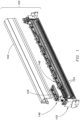
FIG. 1 is an exploded isometric view illustrating a food article foreign material/product/defect removal apparatus in accordance with an example embodiment of the present disclosure and in accordance with at least the independent claim. -
FIG. 2 is a partial exploded isometric view of the removal apparatus illustrated inFIG. 1 . -
FIG. 3 is another partial exploded isometric view of the removal apparatus illustrated inFIG. 1 . -
FIG. 4 is an isometric view of the removal apparatus illustrated inFIG. 1 . -
FIG. 5 is an isometric view illustrating a food article foreign material/product/defect removal apparatus, such as the removal apparatus illustrated inFIG. 1 , where the removal apparatus is employed to remove defective food articles from a food processing line in accordance with an example embodiment of the present disclosure and in accordance with at least the independent claim. -
FIG. 6 is a partial cross-sectional side elevation view of the removal apparatus illustrated inFIG. 1 . -
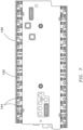
FIG. 7 is a bottom plan view of a driver for a food article foreign material/product/defect removal apparatus, such as the removal apparatus illustrated inFIG. 1 , in accordance with an example embodiment of the present disclosure and in accordance with at least the independent claim. -
FIG. 8 is a top plan view of the driver illustrated inFIG. 7 . -
FIG. 9 is a partial isometric view illustrating an extrusion for a food article foreign material/product/defect removal apparatus, such as the removal apparatus illustrated inFIG. 1 , in accordance with an example embodiment of the present disclosure and in accordance with at least the independent claim. -
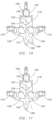
FIG. 10 is an end view illustrating an extrusion for a food article foreign material/product/defect removal apparatus, such as the removal apparatus illustrated inFIG. 1 , where the extrusion includes both straight and slanted nozzles in accordance with an example embodiment of the present disclosure and in accordance with at least the independent claim. -
FIG. 11 is an end view illustrating an extrusion for a food article foreign material/product/defect removal apparatus, such as the removal apparatus illustrated inFIG. 1 , where the extrusion includes straight nozzles in accordance with an example embodiment of the present disclosure and in accordance with at least the independent claim. -
FIG. 12 is an end view illustrating an extrusion for a food article foreign material/product/defect removal apparatus, such as the removal apparatus illustrated inFIG. 1 , where the extrusion includes a second, supplemental extrusion in accordance with an example embodiment of the present disclosure and in accordance with at least the independent claim. -
FIG. 13 is an exploded isometric view of the extrusion and the supplemental extrusion illustrated inFIG. 12 . -
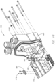
FIG. 14 is a partial exploded isometric view illustrating a food article foreign material/product/defect removal apparatus, where an extrusion is formed with chambers for housing latch mechanisms configured to engage a cover of the removal apparatus in accordance with an example embodiment of the present disclosure and in accordance with at least the independent claim. -
FIG. 15 is a partial exploded isometric view of the removal apparatus illustrated inFIG. 14 . -
FIG. 16 is a partial side elevation view of the removal apparatus illustrated inFIG. 14 . -
FIG. 17 is a partial cross-sectional side elevation view illustrating a food article foreign material/product/defect removal apparatus in accordance with an example embodiment of the present disclosure and in accordance with at least the independent claim. -
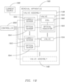
FIG. 18 is a block diagram illustrating a system configured to remove defective food articles from a food processing line, where the system includes a controller and a food article foreign material/product/defect removal apparatus, such as the removal apparatus illustrated inFIG. 17 , where the system can include a computer system, an electronic database, an alert mechanism, valve health check and maintenance equipment, and so forth, where valve health characteristic and data collection can be performed in real-time, and where valve characteristic changes can be detected and history for the life of a valve can be tracked in accordance with example embodiments of the present disclosure and in accordance with at least the independent claim. -
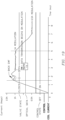
FIG. 19 is a graph illustrating valve current measurements for a valve in a food article foreign material/product/defect removal apparatus, such as the removal apparatus illustrated inFIG. 1 , where the valve current measurements are received from a current sensor connected to the valve, and where the current sensor measurements from the current sensor can be differentiated to determine a back electromotive force (back EMF) to determine whether the valve is healthy in accordance with an example embodiment of the present disclosure and in accordance with at least the independent claim. -
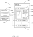
FIG. 20 is a block diagram illustrating a system configured to remove defective food articles from a food processing line, where the system includes a controller and a food article foreign material/product/defect removal apparatus, such as the removal apparatus illustrated inFIG. 1 , in accordance with an example embodiment of the present disclosure and in accordance with at least the independent claim. - Aspects of the disclosure are described more fully hereinafter with reference to the accompanying drawings, which form a part hereof, and which show, by way of illustration, example features. Unless otherwise expressly indicated, example features and embodiments described herein are in accordance with at least the independent claim.
- Referring generally to
FIGS. 1 through 20 , a food article foreign material (FM), product, and/ordefect removal apparatus 100 is described in accordance with example embodiments of the present disclosure. Theremoval apparatus 100 includes amanifold 102 for holding pressurized fluid (e.g., air). Theremoval apparatus 100 also includesvalves 104 that can selectively dispense the pressurized fluid from themanifold 102. Theremoval apparatus 100 is employed to removedefective food articles 106 from a food processing line 108 (e.g., as shown inFIG. 5 ). For example, potatoes are washed, peeled, trimmed, and/or sliced to formindividual food articles 110, which can then be further processed (e.g., de-sugared, blanched, frozen, fried, and so forth) to form french fried potatoes. During processing, thefood articles 110 can be directed into proximity with theremoval apparatus 100, and theremoval apparatus 100 can be used to removedefective food articles 106 from thefood processing line 108. For instance, thefood articles 110 are moved along afirst conveyor 112 and onto asecond conveyor 114. Theremoval apparatus 100 can be positioned between thefirst conveyor 112 and/or one or more drop chutes (not shown) and thesecond conveyor 114. When a defective food article 106 (e.g., a blemished potato strip) is identified, one ormore valves 104 of theremoval apparatus 100 can be used to selectively dispense the pressurized fluid from the manifold 102 (e.g., in the form of an air jet 116) to direct thedefective food article 106 off of thefood processing line 108. Thedefective food article 106 can be collected, discarded, used for a by-product by a food processor, and so on. - It should be noted that while potato food products are described herein with some specificity, the apparatus and techniques of the present disclosure are not meant to be limited to use with a particular food or type of food. Thus, the
removal apparatus 100 can be used with a wide variety offood articles 110, including, but not necessarily limited to, whole foods (e.g., whole potatoes and/or other produce), foods where kernels are removed (e.g., cherries, pitted olives), and so on. Further, theremoval apparatus 100 can be used for removing materials other than food (e.g., foreign material and/or foreign objects) from a processing line. It should also be noted that various equipment can be used to identify adefective food article 106 on thefood processing line 108. For example, theremoval apparatus 100 can be used with optical sorting equipment that identifies the articles to be removed based upon one or more optical characteristics of thefood articles 110. It should also be noted that optical sorting technology is provided by way of example only and is not meant to limit the present disclosure. In other embodiments, adefective food article 106 can be identified using other sorting and/or identification techniques, including other physical sorting and/or identification techniques. - In some embodiments, the
manifold 102 of the foodarticle removal apparatus 100 includes anexterior wall 118 and aninterior wall 120. For example, themanifold 102 is formed using asingle extrusion 122 having a cross-sectional profile that includes theexterior wall 118 and the interior wall 120 (e.g., as shown inFIG. 9 ). Theexterior wall 118 at least partially defines one or more chambers for holding pressurized fluid (e.g., pressurized air). Theinterior wall 120 of themanifold 102 is disposed between two or more of the chambers. For instance, theexterior wall 118 at least partially defines achamber 124, a chamber 126 (and possibly achamber 128, another chamber, and so on), and theinterior wall 120 is disposed between thechamber 124 and thechamber 126, thechamber 124 and thechamber 128, and/or thechamber 126 and thechamber 128. In some embodiments, two or more of thechamber 124, thechamber 126, thechamber 128, and possibly other chambers can be in fluid communication with one another (e.g., connected together so that substantially the entirety of the interior volume of theextrusion 122 can be used to hold pressurized fluid). In this manner,multiple valves 104 of theremoval apparatus 100 can be actuated simultaneously, or at least substantially simultaneously, (e.g., individually and/or as a group) to removedefective food articles 106 from thefood processing line 108. For example, one-fourth (1/4) of the number ofvalves 104 of theremoval apparatus 100, one-half (1/2) of the number ofvalves 104 of theremoval apparatus 100, three-fourths (3/4) of the number ofvalves 104 of theremoval apparatus 100, all of thevalves 104 of theremoval apparatus 100, or another number of thevalves 104 of theremoval apparatus 100 can be actuated simultaneously, or at least substantially simultaneously. - The
exterior wall 118 defineschannels 130 that extend from aside 132 of the manifold 102 into fluid communication with one or more of thechamber 124, thechamber 126, and so forth. Theexterior wall 118 can also definechannels 134 that extend from, for example, aside 136 of the manifold 102 (e.g., opposite theside 132 of the manifold 102) into fluid communication with one or more of thechamber 124, thechamber 128, and so on. Theinterior wall 120 defineschannels 138 that extend from theside 132 of the manifold 102 to aside 140 of themanifold 102. In some embodiments, theinterior wall 120 can also definechannels 142 that extend from theside 136 of the manifold 102 to theside 140 of themanifold 102. As described herein, the arrangement of the chambers within themanifold 102 and the configuration of theexterior wall 118 and theinterior wall 120 can allow for a minimal number of transitions for routing thechannels 138 and/or thechannels 142 through theinterior wall 120. For example, bores 144 drilled into theinterior wall 120 from theside 132 and/or theside 136 of the manifold 102 can connect to bores 146 drilled into theinterior wall 120 from theside 140 of the manifold 102 to form thechannels 138 and/or thechannels 142. In some embodiments, one or more of the channels can be of substantially the same size (e.g., width, cross-sectional area) throughout the channel. In other embodiments, a channel may vary in size (e.g., width, cross-sectional area) from one section of the channel to another. For example, abore 144 may have a different diameter (e.g., larger, smaller) than abore 146. - In some embodiments, the
channels 138 and/or thechannels 142 that extend to theside 140 of the manifold 102 can be oriented to exit the manifold 102 in one or more directions. For example, thechannels 138 and/or 142 shown inFIG. 6 can be angled (e.g., slanted) with respect to theside 140. However, in other embodiments, thechannels 138 and/or 142 can be oriented differently with respect to theside 140. For instance, with reference toFIG. 10 , some of thechannels 138 and/or 142 can be angled, while others can be oriented perpendicularly (e.g., vertically) with respect to theside 140. In further embodiments, all of thechannels 138 and/or 142 can be vertical (e.g., with reference toFIG. 11 ). In some embodiments, thechannels 138 and/or 142 can exit the manifold 102 atnozzles 168, which can be formed as part of theextrusion 122 and then further machined, e.g., withbores 146. Further, it should be noted that theextrusion 122 can be formed withwings 170 that are lifted upwardly from the level of thenozzles 168. This arrangement can facilitate pathways for laser detection beams and so forth. - In some embodiments, one or more additional components can be attached to an extrusion 122 (e.g., to form the nozzles 168). For example, a supplemental extrusion, such as a
plate 172, can be bolted to the extrusion 122 (e.g., with reference toFIGS. 12 and13 ). Theplate 172 can include channels formed through theplate 172 such that the channels exit at ends of thenozzles 168. In some embodiments, these channels can be formed by bores machined from one side of theplate 172 to an opposing side of theplate 172 and/or from one side of theplate 172 and from an opposing side of theplate 172. The bores into theplate 172 can be aligned with, for example, thebores 146 so that thechannels 138 and/or 142 continue through thenozzles 168. Theplate 172 can be removed and replaced (e.g., with a plate having differently oriented nozzles, for cleaning purposes, and so on). Further, aplate 172 can be configured to attach to anextrusion 122 so that there are no exterior fasteners in and/or above the product zone. As shown inFIG. 13 , fasteners (e.g., bolts 174) can be inserted through theextrusion 122 from a side opposite theside 140 and then connected to theplate 172. However, thebolts 174 are provided by way of example and not meant to limit the present disclosure. Thus, in other embodiments different fasteners can be used to secure the plate 172 (or other supplemental extrusions and/or additional components) to theextrusion 122, including, but not necessarily limited to: screws, nuts, rivets, pins, cams, and so forth. - The
valves 104 of the foodarticle removal apparatus 100 are used to selectively connect each one of thechannels 130 and/orchannels 134 to a corresponding one of thechannels 138 and/orchannels 142. In this manner, the pressurized fluid can be selectively dispensed from the chambers within the manifold 102 (e.g., from theside 140 of the manifold 102 or another side of the manifold 102).Multiple valves 104 are included in avalve assembly 148, which is coupled with the foodarticle removal apparatus 100. In this configuration, sections of valves 104 (e.g., ten (10) valves, thirty-two (32) valves, forty-two (42) valves, or a different number of valves) can be operatively coupled with theremoval apparatus 100 as a group (e.g., as opposed to individually wiring each valve to a power source, a controller, and so forth). Thus, when avalve 104 orvalves 104 fails, thevalve 104 orvalves 104 of thevalve assembly 148 can be removed and quickly replaced. In other embodiments, the correspondingvalve assembly 148 can be removed, the failedvalve 104 orvalves 104 can be quickly replaced with anothervalve 104 orvalves 104, and thevalve assembly 148 can be returned to theremoval apparatus 100. In some embodiments, airflow through avalve 104 can be reversed with respect to its ordinary pathway (e.g., as indicated by the manufacturer) so that airflow proceeds from what would otherwise be an outlet of the valve to what would otherwise be an inlet of the valve (e.g., as indicated inFIG. 17 by directional arrow 176). - One or
more valve assemblies 148 include a driver 150 (e.g., comprising a printed circuit board (PCB) 152) operably coupled with thevalves 104, while thevalves 104 are pluggably coupled with thedriver 150. For example, thirty-two (32)valves 104 can be coupled with a driver board. In some embodiments, the printedcircuit board 152 includes stiffeners, thermal material, and so forth. Thedriver 150 includespluggable valve connections 154 for thevalves 104 so that thevalves 104 can be plugged into the driver 150 (e.g., rather than individually wired to the printed circuit board 152). This configuration can prevent or minimize the potential for cross-wiring when connecting thevalves 104 to thedriver 150. Further, one or more alignment pins can be included with avalve assembly 148 to facilitate alignment of avalve 104 with adriver 150, alignment of adriver 150 with the manifold 102, and so on. Thedriver 150 can include connections for supplying power to thevalves 104, providing commands to thevalves 104, and so forth. For example, electrical power is supplied to eachvalve assembly 148 by one or more bus bars extending longitudinally along a header of theremoval apparatus 100. In this manner, thedriver 150 is operable to selectively actuate individual valves 104 (e.g., to removedefective food articles 106 from the food processing line 108). For example, thedriver 150 includes one ormore driver connections 156 for connecting thedriver 150 to a source of electrical power, a communications network (e.g., a computer bus interface), and so forth. For example, thedriver 150 includes one or more of an Ethernet connection port, a ribbon cable connection port, and so forth. - In some embodiments, the
exterior wall 118 of the manifold 102 at least partially defines one or more additional chambers for holding fluid (e.g., air). Further, aninterior wall 158 of the manifold 102 can be disposed between two or more of the chambers. For instance, theexterior wall 118 at least partially defines achamber 160. In this configuration, theinterior wall 158 is disposed between thechamber 160 and thechamber 124. In some embodiments, one or more of thechamber 124, thechamber 126, thechamber 128, and possibly other chambers can be in fluid communication with thechamber 160. Thechamber 160 can be used to supply fluid (e.g., air) to thevalve assemblies 148 for cooling. For example, eachvalve assembly 148 can include one or more cooling ports in fluid communication with thechamber 160. In some embodiments, a cooling port or set of cooling ports is provided for each printedcircuit board 152. - The
removal apparatus 100 can include acover 162 that protects various components of theremoval apparatus 100 within its operating environment, such as thevalves 104. For example, thecover 162 can be used to prevent water from entering the manifold 102 (e.g., when theremoval apparatus 100 is deployed with the food processing line 108). This configuration can allow exterior surfaces of theremoval apparatus 100 to be cleaned in place. In some embodiments, one or more of thevalve assemblies 148 includeshandles 164 that can act as a guide for thecover 162. For example, thehandles 164 can be configured to mate with corresponding grooves or slots defined by an interior of thecover 162. As described herein, thecover 162 does not necessarily include top entries, which could otherwise allow water to enter through thecover 162. Further, theremoval apparatus 100 can include one ormore sealing members 166 configured to seal thecover 162. In some embodiments, theremoval apparatus 100 includes a quad ring sealing member. For instance, one or more 'T'-slot grooves are included, where multiple (e.g., two) 'O'-ring sealing members are disposed in a 'T'-slot groove. - In some embodiments, the
cover 162 can be coupled with the manifold 102 using one ormore latch mechanisms 178 so that the cover can be selectively engaged to secure to themanifold 102. Further, thecover 162 can be secured to the manifold 102 so that thelatch mechanism 178 is covered by thecover 162. For example, the manifold 102 extends longitudinally in a first (e.g., horizontal) direction, and, when thecover 162 is secured to the manifold 102, thelatch mechanism 178 is covered by thecover 162 with respect to a second (e.g., vertical) direction oriented generally perpendicular to the first direction. In some embodiments, alatch mechanism 178 can be disposed in achamber 180 formed in theextrusion 122. For example, one or moreinterior walls 182 are used to separate thechambers 126 and/or 128 from a chamber 180 (e.g., as described with reference toFIG. 17 ). - An end wall of the
extrusion 122 and/or the manifold 102 can define an access to alatch mechanism 178. For example, thelatch mechanism 178 can extend through the end wall of the manifold 102, and can be moved from proximate to the end wall to secure and release thecover 162. In some embodiments, alatch 184 configured as a sliding mechanical wedge can be used to wedge a corresponding part of thecover 162 to secure thecover 162 to the manifold 102 (e.g., as shown inFIGS. 14 through 16 ). However, in other embodiments, alatch 184 can be configured differently. For example, alatch mechanism 178 can be configured as a cam shaft extending through achamber 180 and including one ormore latches 184 configured as cams, with pins extending from thecover 162 that can be engaged by thelatches 184. In this configuration, thelatches 184 can be rotated (e.g., ninety degrees (90°), one hundred and twenty degrees (120°), etc.) to release the pins of thecover 162 from engagement by thelatches 184. Then, thecover 162 can be lifted from themanifold 102. In this manner, thecover 162 can be fastened to the manifold 102 without exterior fasteners in and/or above the product zone. - In another example, a
latch mechanism 178 can be configured as a slide extending through achamber 180 and including one ormore latches 184 configured as magnets (e.g., permanent magnets, such as rare earth magnets, magnetized material, electromagnets, etc.), with material attracted to the magnets disposed on thecover 162 that can be engaged by thelatches 184. In this example, alatch mechanism 178 can slide through achamber 180 to one position where thelatches 184 are aligned with the material attracted to the magnets to secure thecover 162 to the manifold 102, and also slide to another position out of alignment with the magnetically attracted material to disengage thelatches 184 from thecover 162. However, it should be noted that these configurations are provided by way of example and are not meant to limit the present disclosure. Thus, in other embodiments, latchmechanisms 178, latches 184,cover 162, and/ormanifold 102 can be configured differently. For example, thecover 162 can include magnets (e.g., permanent magnets, magnetized material, electromagnets, etc.), with thelatch mechanisms 178 including material attracted to the magnets. - In some embodiments,
valves 104 of theremoval apparatus 100 each include acoil 186 that produces a magnetic field when electrical current is passed through thecoil 186 to operate thevalve 104. For example, one or more of thevalves 104 can be configured as a solenoid valve, and electrical current can be supplied to thecoil 186 of thevalve 104 from acurrent source 188, such as AC mains. Acurrent sensor 192 is configured to connect to the electrical circuit including thecoil 186 and thecurrent source 188. In embodiments of the disclosure, an optical indicator 190 (e.g., a light emitting diode (LED configured as a send diode) or another optical indicator) can be configured to transmit characteristic information about thevalve 104, including, but not necessarily limited to: a number of actuation cycles for the valve 104 (e.g., transmitted as thirty-two (32) bits of data), a unique identification (ID) for the valve 104 (e.g., transmitted as seventy-two (72) bits of data), a firmware version for the valve 104 (e.g., transmitted as eight (8) bits of data), a checksum (e.g., transmitted as eight (8) bits of data), and so on. In some embodiments, the characteristic information about thevalve 104 can be transmitted in less than about one millisecond (1 ms). As described with reference toFIGS. 18 and19 , avalve assembly 148 can also include one or more optical sensors 194 (e.g., an LED configured as a receive diode), each configured to receive an optical indication from a correspondingoptical indicator 190 of eachvalve 104 of thevalve assembly 148. In this manner, optic links optically couple eachoptical indicator 190 of eachvalve 104 to a correspondingoptical sensor 194. - In some embodiments, a
controller 202 for controlling theremoval apparatus 100 is communicatively coupled with theoptical sensors 194 and thecurrent sensor 192. Thecontroller 202 can be configured to receive measurements from thecurrent sensor 192 and determine multiple rates of change of electrical current supplied to a coil 186 (e.g., by differentiating the current measured by the current sensor 192). Thecontroller 202 can then use the rates of change to determine a health of thecorresponding valve 104, and possibly report the health of the valve 104 (e.g., to an operator via a user interface). In embodiments of the disclosure, use of theoptical indicator 190 and theoptical sensor 194 to establish the optic link can provide a cleaner signal for detection and analysis of how avalve 104 responds to being energized to open and/or close. Further, the data can be transmitted in real-time and in parallel with signals transmitted to thevalve 104. - With reference to
FIG. 19 , thecontroller 202 can be configured to determine avalve 104 is healthy using a back electromotive force (back EMF) determined for thevalve 104 based upon differentiating valve current measurements from thecurrent sensor 192. For example, the valve is turned on with a control signal at time zero milliseconds (0 ms), and the back EMF is detected (e.g., a slope of the differentiated current measurements goes negative) between time one millisecond (1 ms) and time two milliseconds (2 ms). In this example, a current of one Ampere (1 A) is used to open thevalve 104. However, the current is initially allowed to rise above this one Ampere (1 A) limit until the back EMF is detected, and then modulation begins at one Ampere (1 A) and can be subsequently adjusted to one-half Ampere (0.5 A). In some embodiments, a limit above one Ampere (1 A) (e.g., a maximum threshold) can be specified so that the current may not rise excessively before a back EMF is detected. Further, real-time detection of back EMF can be used to prevent or minimize over-driving acoil 186 on avalve 104. The valve is then open after time two milliseconds (2 ms). - By detecting the negative value for the back EMF, a determination of a
healthy valve 104 can be made. However, if the back EMF does not go negative, a determination can be made that thevalve 104 is not healthy. Further, in some embodiments, thecontroller 202 can be configured to determine a response time for the corresponding valve based on a back EMF and report the response time of thecorresponding valve 104. Continuing the present example, the response time can be measured from time zero milliseconds (0 ms) to a time between time one millisecond (1 ms) and time two milliseconds (2 ms). In embodiments of the disclosure, characteristic information about avalve 104 can be collected in an offline mode, e.g., by adjusting flow rate, pressure, and so forth, and then actuating avalve 104 and collecting (and possibly filtering) EMF information to establish a baseline for thevalve 104. Further in some embodiments, back EMF, response time, and so forth can be used to determine the degree to which avalve 104 is open. - In some embodiments, the health of a
valve 104 can be determined by comparing optical indications (e.g., one or more health characteristics) received from a correspondingoptical indicator 190 of eachvalve 104 of thevalve assembly 148 to the differentiated valve current measurements for thevalve 104. For example, a back EMF for aparticular valve 104 can be compared with health characteristic information from the valve 104 (e.g., actuation cycles for thevalve 104, a unique identification for thevalve 104, a firmware version for thevalve 104, etc.) to determine a health of thevalve 104. For instance, when a back EMF is determined for avalve 104 as expected, but an unexpected valve identification and/or firmware version is indicated by a correspondingoptical indicator 190 of thevalve 104, a determination can be made that thevalve 104 is unhealthy. In another example, when a back EMF is determined for avalve 104 as expected, but an actuation cycle count is received from a correspondingoptical indicator 190 of thevalve 104 showing a number of actuation cycles for thevalve 104 that has not increased by one (1) as expected, a determination can be made that thevalve 104 is unhealthy. In some embodiments, transmission of optical data including characteristic information about thevalve 104 is not initiated until after modulation of electrical current to the valve 104 (e.g., so that back EMF detection is not corrupted). - In embodiments of the disclosure, valve health information can be generated to indicate the status of a
valve 104 to an operator. Such information can include, for example, time-stamped information about avalve 104, such as current measurements from thecurrent sensor 192, differentiated current measurements, valve response time, one or more optical indications from anoptical indicator 190, and so forth. In some embodiments, the valve health information can be stored (e.g., logged) in an electronic database (e.g., a central system database). Additionally, when a determination of an unhealthy valve is made (e.g., a faulty valve, a valve nearing its end of life, etc.), one or more alerts can be provided to an operator. An alert can be initiated at an indicator, an alarm, an indicator and an alarm, and so forth. In some embodiments, an indicator can include an electronic display (e.g., a central display panel), one or more indicator lights, and so on. Further, an alarm can include an audible alarm, a visual alarm (e.g., an indicator light), a tactile alarm, a signal transmitted to a remote monitoring authority, and so forth. However, these alerts are provided by way of example only and are not meant to limit the present disclosure. In other embodiments, different and/or additional alerts can be initiated. For example, an alert is initiated in the form of an electronic message, such as an email message, a text message, and so on. - In some embodiments, an alert can be initiated using a light emitting device (e.g., a light emitting diode) on a
driver 150, where the location of the light emitting device on thedriver 150 corresponds to the location of aparticular valve 104. In other embodiments, an alert can be initiated using a light emitting device (e.g., a light emitting diode) at the valve 104 (e.g., on a printed circuit board included with the valve). Further, an alert can be provided in the form of a numerical, textual, and/or graphical identification of an unhealthy valve, which may correspond to a marked location on, for example, the extrusion 122 (e.g., a numbered location stamped into the extrusion). The location of anunhealthy valve 104 can also be graphically depicted on a display, such as on a central display panel, and/or on another electronic device, including, but not necessarily limited to: a large touch panel product, an all-in-one computer, a mobile computing device (e.g., a hand-held portable computer, a Personal Digital Assistant (PDA), a laptop computer, a tablet computer, and so forth), a mobile telephone device (e.g., a cellular telephone or a smartphone), a device that includes functionalities associated with smartphones and tablet computers (e.g., a phablet), a surface computing device (e.g., a table top computer), a Personal Computer (PC) device, and so on. Further, in some embodiments,multiple removal apparatus 100 can be coupled with a single display (e.g., a central display panel). In this example,multiple drivers 150 and/orvalves 104 can be graphically depicted, and an operator can manipulate the display (e.g., zoom in, zoom out) to display detailed information aboutparticular drivers 150 and/orvalves 104 and so forth. - Referring now to
FIG. 20 , asystem 200 includes a foodarticle removal apparatus 100 and acontroller 202 for controlling the removal ofdefective food articles 106 from thefood processing line 108. In some embodiments, thecontroller 202 is separate (e.g., remote) from theremoval apparatus 100. In other embodiments, thecontroller 202 is housed with (e.g., within) theremoval apparatus 100. For example, eachdriver 150 can include an associatedcontroller 202. However, in other embodiments, eachdriver 150 does not necessarily include acontroller 202. For example, onecontroller 202 can be connected tomultiple drivers 150, and one or more of thedrivers 150 may then not necessarily include a processor. Thesystem 200, including some or all of its components, can operate under computer control. For example, a processor can be included with or in asystem 200 to control the components and functions ofsystems 200 described herein using software, firmware, hardware (e.g., fixed logic circuitry), manual processing, or a combination thereof. The terms "controller," "functionality," "service," and "logic" as used herein generally represent software, firmware, hardware, or a combination of software, firmware, or hardware in conjunction with controlling thesystems 200. In the case of a software implementation, the module, functionality, or logic represents program code that performs specified tasks when executed on a processor (e.g., central processing unit (CPU) or CPUs). The program code can be stored in one or more computer-readable memory devices (e.g., internal memory and/or one or more tangible media), and so on. The structures, functions, approaches, and techniques described herein can be implemented on a variety of commercial computing platforms having a variety of processors. - The
controller 202 can include aprocessor 204, amemory 206, and acommunications interface 208. Theprocessor 204 provides processing functionality for thecontroller 202 and can include any number of processors, micro-controllers, or other processing systems, and resident or external memory for storing data and other information accessed or generated by thecontroller 202. Theprocessor 204 can execute one or more software programs that implement techniques described herein. Theprocessor 204 is not limited by the materials from which it is formed or the processing mechanisms employed therein and, as such, can be implemented via semiconductor(s) and/or transistors (e.g., using electronic integrated circuit (IC) components), and so forth. - The
memory 206 is an example of tangible, computer-readable storage medium that provides storage functionality to store various data associated with operation of thecontroller 202, such as software programs and/or code segments, or other data to instruct theprocessor 204, and possibly other components of thecontroller 202, to perform the functionality described herein. Thus, thememory 206 can store data, such as a program of instructions for operating the system 200 (including its components), and so forth. It should be noted that while asingle memory 206 is described, a wide variety of types and combinations of memory (e.g., tangible, non-transitory memory) can be employed. Thememory 206 can be integral with theprocessor 204, can comprise stand-alone memory, or can be a combination of both. - The
memory 206 can include, but is not necessarily limited to: removable and non-removable memory components, such as random-access memory (RAM), read-only memory (ROM), flash memory (e.g., a secure digital (SD) memory card, a mini-SD memory card, and/or a micro-SD memory card), magnetic memory, optical memory, universal serial bus (USB) memory devices, hard disk memory, external memory, and so forth. In implementations, theremoval apparatus 100 and/or thememory 206 can include removable integrated circuit card (ICC) memory, such as memory provided by a subscriber identity module (SIM) card, a universal subscriber identity module (USIM) card, a universal integrated circuit card (UICC), and so on. - The
communications interface 208 is operatively configured to communicate with components of thesystem 200. For example, thecommunications interface 208 can be configured to transmit data for storage in thesystem 200, retrieve data from storage in thesystem 200, and so forth. Thecommunications interface 208 is also communicatively coupled with theprocessor 204 to facilitate data transfer between components of thesystem 200 and the processor 204 (e.g., for communicating inputs to theprocessor 204 received from a device communicatively coupled with the controller 202). It should be noted that while thecommunications interface 208 is described as a component of acontroller 202, one or more components of thecommunications interface 208 can be implemented as external components communicatively coupled to thesystem 200 via a wired and/or wireless connection. Thesystem 200 can also comprise and/or connect to one or more input/output (I/O) devices (e.g., via the communications interface 208), including, but not necessarily limited to: a display, a mouse, a touchpad, a keyboard, and so on. - The
communications interface 208 and/or theprocessor 204 can be configured to communicate with a variety of different networks, including, but not necessarily limited to: a wide-area cellular telephone network, such as a 3G cellular network, a 4G cellular network, or a global system for mobile communications (GSM) network; a wireless computer communications network, such as a WiFi network (e.g., a wireless local area network (WLAN) operated using IEEE 802.11 network standards); an internet; the Internet; a wide area network (WAN); a local area network (LAN); a personal area network (PAN) (e.g., a wireless personal area network (WPAN) operated using IEEE 802.15 network standards); a public telephone network; an extranet; an intranet; and so on. However, this list is provided by way of example only and is not meant to limit the present disclosure. Further, thecommunications interface 208 can be configured to communicate with a single network or multiple networks across different access points. - In embodiments of the disclosure, the
controller 202 can be used to monitor health and/or life cycle characteristics of thevalves 104. For example, feedback from avalve 104 can be collected and used to determine a number of actuation cycles for aparticular valve 104. Further, additional information can be collected about avalve 104, e.g., in embodiments where valve circuitry may be powered only when thevalve 104 is actuated. This information can be used to predict when avalve 104 is at or nearing the end of its useful life within thesystem 200. However, actuation cycle counts are provided by way of example only and are not meant to limit the present disclosure. In other embodiments, a feedback loop can be used to determine how many cycles avalve 104 has been in an incorrect orientation (e.g., open when instructed to be shut, shut when instructed to be open). Further, in some embodiments, thesystem 200 tracks a length of time (e.g., in milliseconds) taken by aparticular valve 104 to open and/or close. Additionally, thesystem 200 can also include one or more sensors configured to determine (e.g., sense, measure) an operating characteristic of avalve 104. For example, a back EMF associated with a solenoid is measured for a valve 104 (e.g., as previously described). - Information from a
valve 104 can be collected when thevalve 104 is initially deployed, and subsequent readings can be used to determine when thevalve 104 begins acting erratically and/or slowly, which may be indicative of the end of its useful operating life. In this manner, thesystem 200 can monitor the health ofindividual valves 104,valve assemblies 148, and so forth, and can recommend intervention (e.g., replacement of anindividual valve 104 orvalves 104, maintenance on avalve assembly 148, replacement of avalve assembly 148, and so on). Further, thesystem 200 can initiate validation queries at predetermined and/or random time intervals. In some embodiments, one ormore valves 140 of avalve assembly 148 can be configured as "send only" valves, where information is communicated to thecontroller 202 periodically (e.g., at periodic time intervals, at random time intervals, at pseudo-random time intervals, etc.) and/or at predetermined times (e.g., at scheduled times). However, in other embodiments, thecontroller 202 can initiate a request to receive information from avalve 140, e.g., where one ormore valves 104 are configured as "send and receive" valves. In some embodiments, each valve position within theremoval apparatus 100 can be labeled (e.g., numbered), and information presented to an operator regarding one or more valves can include an identification of the valve associated with its label. - Generally, any of the functions described herein can be implemented using hardware (e.g., fixed logic circuitry such as integrated circuits), software, firmware, manual processing, or a combination thereof. Thus, the blocks discussed in the above disclosure generally represent hardware (e.g., fixed logic circuitry such as integrated circuits), software, firmware, or a combination thereof. In the instance of a hardware configuration, the various blocks discussed in the above disclosure may be implemented as integrated circuits along with other functionality. Such integrated circuits may include all of the functions of a given block, system, or circuit, or a portion of the functions of the block, system, or circuit. Further, elements of the blocks, systems, or circuits may be implemented across multiple integrated circuits. Such integrated circuits may comprise various integrated circuits, including, but not necessarily limited to: a monolithic integrated circuit, a flip chip integrated circuit, a multichip module integrated circuit, and/or a mixed signal integrated circuit. In the instance of a software implementation, the various blocks discussed in the above disclosure represent executable instructions (e.g., program code) that perform specified tasks when executed on a processor. These executable instructions can be stored in one or more tangible computer readable media. In some such instances, the entire system, block, or circuit may be implemented using its software or firmware equivalent. In other instances, one part of a given system, block, or circuit may be implemented in software or firmware, while other parts are implemented in hardware.
- Although the subject matter has been described in language specific to structural features and/or methodological acts, it is to be understood that the subject matter defined in the appended claims is not necessarily limited to the specific features or acts described above. Rather, the specific features and acts described above are disclosed as example forms of implementing the invention as defined by the claims.
Claims (14)
- A food article defect removal apparatus (100) for removing defective food articles (106) from a food processing line (108), the food article defect removal apparatus (100) comprising:a manifold (102) at least partially defining a chamber (124, 126, 128, 160) configured for holding pressurized fluid, a first plurality of channels (130, 134) extending from a first side (132, 136) of the manifold (102) into fluid communication with the chamber (124, 126, 128, 160), and a second plurality of channels (138, 142) extending from the first side (132, 136) of the manifold to a second side (140) of the manifold (102); anda valve assembly (148) comprising:characterised in that the valve assembly (148) further comprises:
a plurality of valves (104) selectively connecting each one of the first plurality of channels (130, 134) to a corresponding one of the second plurality of channels (138, 142) for selectively dispensing the pressurized fluid from the second side (140) of the manifold (102),
a driver (150) operably coupled with the plurality of valves (104) for selectively actuating individual ones of the plurality of valves (104), the plurality of valves pluggably coupled with the driver (150). - The food article defect removal apparatus (100) as recited in Claim 1, wherein the first side (132, 136) of the manifold (102) is different from the second side (140) of the manifold (102).
- The food article defect removal apparatus (100) as recited in any one of the above claims, wherein the driver (150) comprises a printed circuit board (152).
- The food article defect removal apparatus (100) as recited in any of the above claims, further comprising a second valve assembly (148) comprising a second plurality of valves (104) and a second driver (150) pluggably coupled with the second plurality of valves (104).
- The food article defect removal apparatus (100) as recited in any of the above claims, wherein the driver (150) comprises at least one of a power connection or a communications network connection to facilitate selective actuation of individual ones of the plurality of valves (104).
- The food article defect removal apparatus (100) as recited in any one of the above claims, wherein the valve assembly (148) comprises a cooling port in fluid communication with the chamber (160) of the manifold (102) for cooling the valve assembly (148).
- The food article defect removal apparatus (100) as recited in any one of the above claims, further comprising a cover (162) for covering the valve assembly (148), wherein the valve assembly (148) comprises a handle (164) configured to align the cover (162).
- The food article defect removal apparatus (100) as recited in any one of the above claims, further comprising:the plurality of valves (104) each including a coil (186) configured to produce a magnetic field when electrical current is passed through the coil (186) to operate the valve (104), and an optical indicator (190) to transmit at least one health characteristic of the valve (104);a plurality of optical sensors (194) each configured to receive an optical indication from a corresponding optical indicator (190) of each valve of the plurality of valves (104);a plurality of optic links optically coupling each optical indicator (190) of each valve of the plurality of valves (104) to a corresponding optical sensor (194) of the plurality of optical sensors (194);a current sensor (192) configured to connect to an electrical circuit including the coil (186) and a current source (188) for supplying electrical current to the coil (186); anda controller (202) communicatively coupled with the plurality of optical sensors (194) and the current sensor (192), the controller (202) configured to receive measurements from the current sensor (192), determine a plurality of rates of change of electrical current supplied to the coil (186), use the rates of change to determine a health of the corresponding valve (104), and report the health of the corresponding valve (104).
- The food article defect removal apparatus (100) as recited in Claim 8, wherein the controller (202) is configured to receive an optical indication from an optical indicator (190) of the plurality of optical indicators (190), the plurality of rates of change of electrical current supplied to the coil (186) are determined by differentiating the current measured by the current sensor (192), and the health of the corresponding valve (104) is determined by comparing the optical indication to the plurality of rates of change of the corresponding valve (104).
- The food article defect removal apparatus (100) as recited in Claim 8 or 9, wherein the valve (104) comprises a solenoid valve.
- The food article defect removal apparatus (100) as recited in any one of Claims 8 to 10, wherein the optical indicator (190) comprises a light emitting diode.
- The food article defect removal apparatus (100) as recited in any one of Claims 8 to 11, wherein the controller (202) is configured to determine the valve (104) is unhealthy when a back electromotive force determined for the valve (104) based upon the plurality of rates of change does not correspond to an optical indication from the optical indicator (190) that electrical current is passing through the coil (186).
- The food article defect removal apparatus (100) as recited in any one of Claims 8 to 12, wherein the controller (202) is configured to determine the valve (104) is unhealthy when an optical indication from the optical indicator (190) that electrical current is passing through the coil (186) does not correspond to a back electromotive force determined for the valve (104).
- The food article defect removal apparatus (100) as recited in any one of Claims 8 to 13, wherein the controller (202) is configured to determine a response time for the corresponding valve (104) based upon at least one of the optical indication or the plurality of rates of change and report the response time of the corresponding valve (104).
Applications Claiming Priority (5)
| Application Number | Priority Date | Filing Date | Title |
|---|---|---|---|
| US15/132,416 US10052663B2 (en) | 2016-04-19 | 2016-04-19 | Food article defect removal apparatus |
| US15/132,315 US10092931B2 (en) | 2016-04-19 | 2016-04-19 | Food article defect removal apparatus |
| US15/132,337 US10478864B2 (en) | 2016-04-19 | 2016-04-19 | Food article defect removal apparatus |
| US15/132,352 US10753507B2 (en) | 2016-04-19 | 2016-04-19 | Food article defect removal apparatus |
| PCT/US2017/028030 WO2017184540A1 (en) | 2016-04-19 | 2017-04-18 | Food article defect removal apparatus |
Publications (3)
| Publication Number | Publication Date |
|---|---|
| EP3445502A1 EP3445502A1 (en) | 2019-02-27 |
| EP3445502A4 EP3445502A4 (en) | 2019-11-20 |
| EP3445502B1 true EP3445502B1 (en) | 2023-11-29 |
Family
ID=60116493
Family Applications (1)
| Application Number | Title | Priority Date | Filing Date |
|---|---|---|---|
| EP17786432.9A Active EP3445502B1 (en) | 2016-04-19 | 2017-04-18 | Food article defect removal apparatus |
Country Status (5)
| Country | Link |
|---|---|
| EP (1) | EP3445502B1 (en) |
| CN (2) | CN113019996B (en) |
| AU (3) | AU2017254462B2 (en) |
| CA (1) | CA3020961A1 (en) |
| WO (1) | WO2017184540A1 (en) |
Families Citing this family (2)
| Publication number | Priority date | Publication date | Assignee | Title |
|---|---|---|---|---|
| CN109954686A (en) * | 2019-04-17 | 2019-07-02 | 王兴云 | A kind of automatic centering and coring machine and method thereof |
| SE547330C2 (en) * | 2022-06-09 | 2025-07-01 | Staccato Tech Ab | An electromechanical valve |
Family Cites Families (19)
| Publication number | Priority date | Publication date | Assignee | Title |
|---|---|---|---|---|
| US4576071A (en) * | 1983-08-04 | 1986-03-18 | Lamb-Weston, Inc. | Food product defect sensor and trimmer apparatus |
| AU3147893A (en) * | 1991-11-26 | 1993-06-28 | Alpine Technology, Inc. | Glass cullet separator and method of using same |
| US5495871A (en) * | 1995-04-03 | 1996-03-05 | The Aro Corporation | Multiple valve manifold with plural power supplies |
| US5659624A (en) * | 1995-09-01 | 1997-08-19 | Fazzari; Rodney J. | High speed mass flow food sorting appartus for optically inspecting and sorting bulk food products |
| US6397797B1 (en) * | 2000-12-08 | 2002-06-04 | Ford Global Technologies, Inc. | Method of controlling valve landing in a camless engine |
| US6727452B2 (en) * | 2002-01-03 | 2004-04-27 | Fmc Technologies, Inc. | System and method for removing defects from citrus pulp |
| US20060226056A1 (en) * | 2005-04-08 | 2006-10-12 | Satake Usa, Inc. | Tubeless Ejector Manifold for Use with Sorter |
| CN201132145Y (en) * | 2007-10-26 | 2008-10-15 | 天津市华核科技有限公司 | Integrated nozzle device for novel color sorter |
| US7765971B1 (en) * | 2008-01-09 | 2010-08-03 | Overacker Bernard S | Valve cover system |
| ATE505271T1 (en) * | 2008-09-29 | 2011-04-15 | Abb As | COLOR CHANGING VALVE ARRANGEMENT WITH SENSORS |
| NL2002209C2 (en) * | 2008-11-14 | 2010-05-17 | Asco Controls Bv | Solenoid valve with sensor for determining stroke, velocities and/or accelerations of a moveable core of the valve as indication of failure modus and health status. |
| DE102009006654B3 (en) * | 2009-01-29 | 2010-10-14 | Numatics Gmbh | Pneumatic multi-port valve for use in pneumatic operated sorting system, has circular orifice formed between sliding element and controlled-sleeve, so that flush volume flow runs between fluid connections in closed position |
| JP5019303B2 (en) * | 2010-03-03 | 2012-09-05 | Smc株式会社 | Electromagnetic valve driving circuit, electromagnetic valve, and electromagnetic valve driving method |
| JP5625600B2 (en) * | 2010-08-05 | 2014-11-19 | 株式会社サタケ | Ejector system for color sorter |
| US8839815B2 (en) * | 2011-12-15 | 2014-09-23 | Honeywell International Inc. | Gas valve with electronic cycle counter |
| DE102012005936B4 (en) * | 2012-03-26 | 2022-11-24 | Bürkert Werke GmbH | Solenoid valve with a condition monitoring unit and method for condition monitoring of a solenoid valve |
| US8873965B2 (en) * | 2012-04-10 | 2014-10-28 | Disney Enterprises, Inc. | Visible light communication with flickering prevention |
| US9702349B2 (en) * | 2013-03-15 | 2017-07-11 | ClearMotion, Inc. | Active vehicle suspension system |
| EP2923777B1 (en) * | 2014-03-24 | 2016-07-27 | FESTO AG & Co. KG | Sorting device |
-
2017
- 2017-04-18 EP EP17786432.9A patent/EP3445502B1/en active Active
- 2017-04-18 AU AU2017254462A patent/AU2017254462B2/en active Active
- 2017-04-18 CA CA3020961A patent/CA3020961A1/en active Pending
- 2017-04-18 CN CN202110226187.7A patent/CN113019996B/en active Active
- 2017-04-18 WO PCT/US2017/028030 patent/WO2017184540A1/en not_active Ceased
- 2017-04-18 CN CN201780037813.XA patent/CN109311061B/en active Active
-
2022
- 2022-06-23 AU AU2022204416A patent/AU2022204416B2/en active Active
-
2024
- 2024-05-31 AU AU2024203684A patent/AU2024203684B2/en active Active
Also Published As
| Publication number | Publication date |
|---|---|
| NZ747134A (en) | 2024-10-25 |
| CN109311061B (en) | 2021-03-16 |
| EP3445502A1 (en) | 2019-02-27 |
| AU2024203684A1 (en) | 2024-06-20 |
| CN113019996A (en) | 2021-06-25 |
| CA3020961A1 (en) | 2017-10-26 |
| AU2017254462B2 (en) | 2022-03-31 |
| NZ786460A (en) | 2024-11-29 |
| AU2022204416B2 (en) | 2024-06-20 |
| AU2024203684B2 (en) | 2026-04-16 |
| AU2017254462A1 (en) | 2018-11-01 |
| WO2017184540A1 (en) | 2017-10-26 |
| CN109311061A (en) | 2019-02-05 |
| CN113019996B (en) | 2023-09-29 |
| AU2022204416A1 (en) | 2022-07-14 |
| EP3445502A4 (en) | 2019-11-20 |
Similar Documents
| Publication | Publication Date | Title |
|---|---|---|
| AU2024203684A1 (en) | Food article defect removal apparatus | |
| US10092931B2 (en) | Food article defect removal apparatus | |
| US12276354B2 (en) | Food article defect removal apparatus | |
| US20180164781A1 (en) | Numerical controller and machine learning device | |
| US10052663B2 (en) | Food article defect removal apparatus | |
| US20140028462A1 (en) | Reconfigurable equipment monitoring systems and methods | |
| KR102216607B1 (en) | Liquid analyser | |
| CN214516069U (en) | Material detection device and production equipment | |
| CN101573610A (en) | Interchangeable accessories | |
| US10478864B2 (en) | Food article defect removal apparatus | |
| EP3023953B1 (en) | System and method of airflow monitoring for variable airflow environments | |
| CN105848393A (en) | Fault detection apparatus and method | |
| CN105425739B (en) | Carry out the system of predicted anomaly generation using PLC daily record data | |
| CN104941921A (en) | Automatic magnetic steel temperature controller detection line | |
| EP1239277A1 (en) | Measurement arrangement | |
| KR20160024705A (en) | A sensor gathering biometics of livestock | |
| CN112595949A (en) | Automatic wafer testing device and testing method | |
| CN204188372U (en) | Breaker of plastic casing mechanical life test device | |
| US10401303B1 (en) | Lighting apparatus for conveyors | |
| CN104525508A (en) | Machine vision degraded product discharge system | |
| Rayala et al. | Colour detection and sorting of objects using IoT | |
| CN104006711B (en) | Semicircle testing device | |
| EP2697628A1 (en) | Chemical- physical sensing device for chemical - toxicological diagnostics in real matrices | |
| Lindner et al. | A straightforward approach to introduce FDC-methods for wet-process-equipment | |
| JP2007101246A (en) | Workpiece inspection system |
Legal Events
| Date | Code | Title | Description |
|---|---|---|---|
| STAA | Information on the status of an ep patent application or granted ep patent |
Free format text: STATUS: THE INTERNATIONAL PUBLICATION HAS BEEN MADE |
|
| PUAI | Public reference made under article 153(3) epc to a published international application that has entered the european phase |
Free format text: ORIGINAL CODE: 0009012 |
|
| STAA | Information on the status of an ep patent application or granted ep patent |
Free format text: STATUS: REQUEST FOR EXAMINATION WAS MADE |
|
| 17P | Request for examination filed |
Effective date: 20181108 |
|
| AK | Designated contracting states |
Kind code of ref document: A1 Designated state(s): AL AT BE BG CH CY CZ DE DK EE ES FI FR GB GR HR HU IE IS IT LI LT LU LV MC MK MT NL NO PL PT RO RS SE SI SK SM TR |
|
| AX | Request for extension of the european patent |
Extension state: BA ME |
|
| DAV | Request for validation of the european patent (deleted) | ||
| DAX | Request for extension of the european patent (deleted) | ||
| A4 | Supplementary search report drawn up and despatched |
Effective date: 20191023 |
|
| RIC1 | Information provided on ipc code assigned before grant |
Ipc: B07C 5/36 20060101AFI20191017BHEP |
|
| STAA | Information on the status of an ep patent application or granted ep patent |
Free format text: STATUS: EXAMINATION IS IN PROGRESS |
|
| 17Q | First examination report despatched |
Effective date: 20210331 |
|
| GRAP | Despatch of communication of intention to grant a patent |
Free format text: ORIGINAL CODE: EPIDOSNIGR1 |
|
| STAA | Information on the status of an ep patent application or granted ep patent |
Free format text: STATUS: GRANT OF PATENT IS INTENDED |
|
| P01 | Opt-out of the competence of the unified patent court (upc) registered |
Effective date: 20230521 |
|
| INTG | Intention to grant announced |
Effective date: 20230622 |
|
| GRAS | Grant fee paid |
Free format text: ORIGINAL CODE: EPIDOSNIGR3 |
|
| GRAA | (expected) grant |
Free format text: ORIGINAL CODE: 0009210 |
|
| STAA | Information on the status of an ep patent application or granted ep patent |
Free format text: STATUS: THE PATENT HAS BEEN GRANTED |
|
| AK | Designated contracting states |
Kind code of ref document: B1 Designated state(s): AL AT BE BG CH CY CZ DE DK EE ES FI FR GB GR HR HU IE IS IT LI LT LU LV MC MK MT NL NO PL PT RO RS SE SI SK SM TR |
|
| REG | Reference to a national code |
Ref country code: GB Ref legal event code: FG4D |
|
| REG | Reference to a national code |
Ref country code: CH Ref legal event code: EP |
|
| REG | Reference to a national code |
Ref country code: DE Ref legal event code: R096 Ref document number: 602017077007 Country of ref document: DE |
|
| REG | Reference to a national code |
Ref country code: IE Ref legal event code: FG4D |
|
| REG | Reference to a national code |
Ref country code: NL Ref legal event code: FP |
|
| REG | Reference to a national code |
Ref country code: LT Ref legal event code: MG9D |
|
| PG25 | Lapsed in a contracting state [announced via postgrant information from national office to epo] |
Ref country code: GR Free format text: LAPSE BECAUSE OF FAILURE TO SUBMIT A TRANSLATION OF THE DESCRIPTION OR TO PAY THE FEE WITHIN THE PRESCRIBED TIME-LIMIT Effective date: 20240301 |
|
| PG25 | Lapsed in a contracting state [announced via postgrant information from national office to epo] |
Ref country code: IS Free format text: LAPSE BECAUSE OF FAILURE TO SUBMIT A TRANSLATION OF THE DESCRIPTION OR TO PAY THE FEE WITHIN THE PRESCRIBED TIME-LIMIT Effective date: 20240329 |
|
| PG25 | Lapsed in a contracting state [announced via postgrant information from national office to epo] |
Ref country code: LT Free format text: LAPSE BECAUSE OF FAILURE TO SUBMIT A TRANSLATION OF THE DESCRIPTION OR TO PAY THE FEE WITHIN THE PRESCRIBED TIME-LIMIT Effective date: 20231129 |
|
| PG25 | Lapsed in a contracting state [announced via postgrant information from national office to epo] |
Ref country code: ES Free format text: LAPSE BECAUSE OF FAILURE TO SUBMIT A TRANSLATION OF THE DESCRIPTION OR TO PAY THE FEE WITHIN THE PRESCRIBED TIME-LIMIT Effective date: 20231129 |
|
| PG25 | Lapsed in a contracting state [announced via postgrant information from national office to epo] |
Ref country code: LT Free format text: LAPSE BECAUSE OF FAILURE TO SUBMIT A TRANSLATION OF THE DESCRIPTION OR TO PAY THE FEE WITHIN THE PRESCRIBED TIME-LIMIT Effective date: 20231129 Ref country code: IS Free format text: LAPSE BECAUSE OF FAILURE TO SUBMIT A TRANSLATION OF THE DESCRIPTION OR TO PAY THE FEE WITHIN THE PRESCRIBED TIME-LIMIT Effective date: 20240329 Ref country code: GR Free format text: LAPSE BECAUSE OF FAILURE TO SUBMIT A TRANSLATION OF THE DESCRIPTION OR TO PAY THE FEE WITHIN THE PRESCRIBED TIME-LIMIT Effective date: 20240301 Ref country code: ES Free format text: LAPSE BECAUSE OF FAILURE TO SUBMIT A TRANSLATION OF THE DESCRIPTION OR TO PAY THE FEE WITHIN THE PRESCRIBED TIME-LIMIT Effective date: 20231129 Ref country code: BG Free format text: LAPSE BECAUSE OF FAILURE TO SUBMIT A TRANSLATION OF THE DESCRIPTION OR TO PAY THE FEE WITHIN THE PRESCRIBED TIME-LIMIT Effective date: 20240229 |
|
| REG | Reference to a national code |
Ref country code: AT Ref legal event code: MK05 Ref document number: 1635580 Country of ref document: AT Kind code of ref document: T Effective date: 20231129 |
|
| PG25 | Lapsed in a contracting state [announced via postgrant information from national office to epo] |
Ref country code: SE Free format text: LAPSE BECAUSE OF FAILURE TO SUBMIT A TRANSLATION OF THE DESCRIPTION OR TO PAY THE FEE WITHIN THE PRESCRIBED TIME-LIMIT Effective date: 20231129 Ref country code: RS Free format text: LAPSE BECAUSE OF FAILURE TO SUBMIT A TRANSLATION OF THE DESCRIPTION OR TO PAY THE FEE WITHIN THE PRESCRIBED TIME-LIMIT Effective date: 20231129 Ref country code: PL Free format text: LAPSE BECAUSE OF FAILURE TO SUBMIT A TRANSLATION OF THE DESCRIPTION OR TO PAY THE FEE WITHIN THE PRESCRIBED TIME-LIMIT Effective date: 20231129 Ref country code: NO Free format text: LAPSE BECAUSE OF FAILURE TO SUBMIT A TRANSLATION OF THE DESCRIPTION OR TO PAY THE FEE WITHIN THE PRESCRIBED TIME-LIMIT Effective date: 20240229 Ref country code: LV Free format text: LAPSE BECAUSE OF FAILURE TO SUBMIT A TRANSLATION OF THE DESCRIPTION OR TO PAY THE FEE WITHIN THE PRESCRIBED TIME-LIMIT Effective date: 20231129 Ref country code: HR Free format text: LAPSE BECAUSE OF FAILURE TO SUBMIT A TRANSLATION OF THE DESCRIPTION OR TO PAY THE FEE WITHIN THE PRESCRIBED TIME-LIMIT Effective date: 20231129 |
|
| PG25 | Lapsed in a contracting state [announced via postgrant information from national office to epo] |
Ref country code: DK Free format text: LAPSE BECAUSE OF FAILURE TO SUBMIT A TRANSLATION OF THE DESCRIPTION OR TO PAY THE FEE WITHIN THE PRESCRIBED TIME-LIMIT Effective date: 20231129 |
|
| PG25 | Lapsed in a contracting state [announced via postgrant information from national office to epo] |
Ref country code: CZ Free format text: LAPSE BECAUSE OF FAILURE TO SUBMIT A TRANSLATION OF THE DESCRIPTION OR TO PAY THE FEE WITHIN THE PRESCRIBED TIME-LIMIT Effective date: 20231129 Ref country code: AT Free format text: LAPSE BECAUSE OF FAILURE TO SUBMIT A TRANSLATION OF THE DESCRIPTION OR TO PAY THE FEE WITHIN THE PRESCRIBED TIME-LIMIT Effective date: 20231129 |
|
| PG25 | Lapsed in a contracting state [announced via postgrant information from national office to epo] |
Ref country code: SK Free format text: LAPSE BECAUSE OF FAILURE TO SUBMIT A TRANSLATION OF THE DESCRIPTION OR TO PAY THE FEE WITHIN THE PRESCRIBED TIME-LIMIT Effective date: 20231129 |
|
| PG25 | Lapsed in a contracting state [announced via postgrant information from national office to epo] |
Ref country code: SM Free format text: LAPSE BECAUSE OF FAILURE TO SUBMIT A TRANSLATION OF THE DESCRIPTION OR TO PAY THE FEE WITHIN THE PRESCRIBED TIME-LIMIT Effective date: 20231129 Ref country code: SK Free format text: LAPSE BECAUSE OF FAILURE TO SUBMIT A TRANSLATION OF THE DESCRIPTION OR TO PAY THE FEE WITHIN THE PRESCRIBED TIME-LIMIT Effective date: 20231129 Ref country code: RO Free format text: LAPSE BECAUSE OF FAILURE TO SUBMIT A TRANSLATION OF THE DESCRIPTION OR TO PAY THE FEE WITHIN THE PRESCRIBED TIME-LIMIT Effective date: 20231129 Ref country code: IT Free format text: LAPSE BECAUSE OF FAILURE TO SUBMIT A TRANSLATION OF THE DESCRIPTION OR TO PAY THE FEE WITHIN THE PRESCRIBED TIME-LIMIT Effective date: 20231129 Ref country code: EE Free format text: LAPSE BECAUSE OF FAILURE TO SUBMIT A TRANSLATION OF THE DESCRIPTION OR TO PAY THE FEE WITHIN THE PRESCRIBED TIME-LIMIT Effective date: 20231129 Ref country code: DK Free format text: LAPSE BECAUSE OF FAILURE TO SUBMIT A TRANSLATION OF THE DESCRIPTION OR TO PAY THE FEE WITHIN THE PRESCRIBED TIME-LIMIT Effective date: 20231129 Ref country code: CZ Free format text: LAPSE BECAUSE OF FAILURE TO SUBMIT A TRANSLATION OF THE DESCRIPTION OR TO PAY THE FEE WITHIN THE PRESCRIBED TIME-LIMIT Effective date: 20231129 Ref country code: AT Free format text: LAPSE BECAUSE OF FAILURE TO SUBMIT A TRANSLATION OF THE DESCRIPTION OR TO PAY THE FEE WITHIN THE PRESCRIBED TIME-LIMIT Effective date: 20231129 |
|
| PG25 | Lapsed in a contracting state [announced via postgrant information from national office to epo] |
Ref country code: PT Free format text: LAPSE BECAUSE OF FAILURE TO SUBMIT A TRANSLATION OF THE DESCRIPTION OR TO PAY THE FEE WITHIN THE PRESCRIBED TIME-LIMIT Effective date: 20240401 |
|
| PG25 | Lapsed in a contracting state [announced via postgrant information from national office to epo] |
Ref country code: PT Free format text: LAPSE BECAUSE OF FAILURE TO SUBMIT A TRANSLATION OF THE DESCRIPTION OR TO PAY THE FEE WITHIN THE PRESCRIBED TIME-LIMIT Effective date: 20240401 |
|
| REG | Reference to a national code |
Ref country code: DE Ref legal event code: R097 Ref document number: 602017077007 Country of ref document: DE |
|
| PLBE | No opposition filed within time limit |
Free format text: ORIGINAL CODE: 0009261 |
|
| STAA | Information on the status of an ep patent application or granted ep patent |
Free format text: STATUS: NO OPPOSITION FILED WITHIN TIME LIMIT |
|
| PG25 | Lapsed in a contracting state [announced via postgrant information from national office to epo] |
Ref country code: SI Free format text: LAPSE BECAUSE OF FAILURE TO SUBMIT A TRANSLATION OF THE DESCRIPTION OR TO PAY THE FEE WITHIN THE PRESCRIBED TIME-LIMIT Effective date: 20231129 |
|
| PG25 | Lapsed in a contracting state [announced via postgrant information from national office to epo] |
Ref country code: SI Free format text: LAPSE BECAUSE OF FAILURE TO SUBMIT A TRANSLATION OF THE DESCRIPTION OR TO PAY THE FEE WITHIN THE PRESCRIBED TIME-LIMIT Effective date: 20231129 |
|
| 26N | No opposition filed |
Effective date: 20240830 |
|
| PG25 | Lapsed in a contracting state [announced via postgrant information from national office to epo] |
Ref country code: MC Free format text: LAPSE BECAUSE OF FAILURE TO SUBMIT A TRANSLATION OF THE DESCRIPTION OR TO PAY THE FEE WITHIN THE PRESCRIBED TIME-LIMIT Effective date: 20231129 |
|
| PG25 | Lapsed in a contracting state [announced via postgrant information from national office to epo] |
Ref country code: MC Free format text: LAPSE BECAUSE OF FAILURE TO SUBMIT A TRANSLATION OF THE DESCRIPTION OR TO PAY THE FEE WITHIN THE PRESCRIBED TIME-LIMIT Effective date: 20231129 |
|
| REG | Reference to a national code |
Ref country code: CH Ref legal event code: PL |
|
| PG25 | Lapsed in a contracting state [announced via postgrant information from national office to epo] |
Ref country code: LU Free format text: LAPSE BECAUSE OF NON-PAYMENT OF DUE FEES Effective date: 20240418 |
|
| PG25 | Lapsed in a contracting state [announced via postgrant information from national office to epo] |
Ref country code: LU Free format text: LAPSE BECAUSE OF NON-PAYMENT OF DUE FEES Effective date: 20240418 |
|
| PG25 | Lapsed in a contracting state [announced via postgrant information from national office to epo] |
Ref country code: FR Free format text: LAPSE BECAUSE OF NON-PAYMENT OF DUE FEES Effective date: 20240430 |
|
| PG25 | Lapsed in a contracting state [announced via postgrant information from national office to epo] |
Ref country code: FR Free format text: LAPSE BECAUSE OF NON-PAYMENT OF DUE FEES Effective date: 20240430 Ref country code: CH Free format text: LAPSE BECAUSE OF NON-PAYMENT OF DUE FEES Effective date: 20240430 |
|
| PG25 | Lapsed in a contracting state [announced via postgrant information from national office to epo] |
Ref country code: IE Free format text: LAPSE BECAUSE OF NON-PAYMENT OF DUE FEES Effective date: 20240418 |
|
| PG25 | Lapsed in a contracting state [announced via postgrant information from national office to epo] |
Ref country code: CY Free format text: LAPSE BECAUSE OF FAILURE TO SUBMIT A TRANSLATION OF THE DESCRIPTION OR TO PAY THE FEE WITHIN THE PRESCRIBED TIME-LIMIT; INVALID AB INITIO Effective date: 20170418 |
|
| PG25 | Lapsed in a contracting state [announced via postgrant information from national office to epo] |
Ref country code: HU Free format text: LAPSE BECAUSE OF FAILURE TO SUBMIT A TRANSLATION OF THE DESCRIPTION OR TO PAY THE FEE WITHIN THE PRESCRIBED TIME-LIMIT; INVALID AB INITIO Effective date: 20170418 |
|
| PG25 | Lapsed in a contracting state [announced via postgrant information from national office to epo] |
Ref country code: FI Free format text: LAPSE BECAUSE OF FAILURE TO SUBMIT A TRANSLATION OF THE DESCRIPTION OR TO PAY THE FEE WITHIN THE PRESCRIBED TIME-LIMIT Effective date: 20231129 |
|
| PGFP | Annual fee paid to national office [announced via postgrant information from national office to epo] |
Ref country code: NL Payment date: 20260426 Year of fee payment: 10 |
|
| PG25 | Lapsed in a contracting state [announced via postgrant information from national office to epo] |
Ref country code: TR Free format text: LAPSE BECAUSE OF FAILURE TO SUBMIT A TRANSLATION OF THE DESCRIPTION OR TO PAY THE FEE WITHIN THE PRESCRIBED TIME-LIMIT Effective date: 20231129 |
|
| PGFP | Annual fee paid to national office [announced via postgrant information from national office to epo] |
Ref country code: GB Payment date: 20260427 Year of fee payment: 10 |
|
| PGFP | Annual fee paid to national office [announced via postgrant information from national office to epo] |
Ref country code: DE Payment date: 20260429 Year of fee payment: 10 |
|
| PGFP | Annual fee paid to national office [announced via postgrant information from national office to epo] |
Ref country code: BE Payment date: 20260427 Year of fee payment: 10 |