EP3445294B1 - Gewebestent - Google Patents
Gewebestent Download PDFInfo
- Publication number
- EP3445294B1 EP3445294B1 EP17720054.0A EP17720054A EP3445294B1 EP 3445294 B1 EP3445294 B1 EP 3445294B1 EP 17720054 A EP17720054 A EP 17720054A EP 3445294 B1 EP3445294 B1 EP 3445294B1
- Authority
- EP
- European Patent Office
- Prior art keywords
- tissue
- stent according
- anyone
- tissue stent
- mesh
- Prior art date
- Legal status (The legal status is an assumption and is not a legal conclusion. Google has not performed a legal analysis and makes no representation as to the accuracy of the status listed.)
- Active
Links
Images


Classifications
-
- A—HUMAN NECESSITIES
- A61—MEDICAL OR VETERINARY SCIENCE; HYGIENE
- A61F—FILTERS IMPLANTABLE INTO BLOOD VESSELS; PROSTHESES; DEVICES PROVIDING PATENCY TO, OR PREVENTING COLLAPSING OF, TUBULAR STRUCTURES OF THE BODY, e.g. STENTS; ORTHOPAEDIC, NURSING OR CONTRACEPTIVE DEVICES; FOMENTATION; TREATMENT OR PROTECTION OF EYES OR EARS; BANDAGES, DRESSINGS OR ABSORBENT PADS; FIRST-AID KITS
- A61F2/00—Filters implantable into blood vessels; Prostheses, i.e. artificial substitutes or replacements for parts of the body; Appliances for connecting them with the body; Devices providing patency to, or preventing collapsing of, tubular structures of the body, e.g. stents
- A61F2/82—Devices providing patency to, or preventing collapsing of, tubular structures of the body, e.g. stents
- A61F2/86—Stents in a form characterised by the wire-like elements; Stents in the form characterised by a net-like or mesh-like structure
- A61F2/90—Stents in a form characterised by the wire-like elements; Stents in the form characterised by a net-like or mesh-like structure characterised by a net-like or mesh-like structure
-
- A—HUMAN NECESSITIES
- A61—MEDICAL OR VETERINARY SCIENCE; HYGIENE
- A61B—DIAGNOSIS; SURGERY; IDENTIFICATION
- A61B5/00—Measuring for diagnostic purposes; Identification of persons
- A61B5/0002—Remote monitoring of patients using telemetry, e.g. transmission of vital signals via a communication network
- A61B5/0031—Implanted circuitry
-
- A—HUMAN NECESSITIES
- A61—MEDICAL OR VETERINARY SCIENCE; HYGIENE
- A61B—DIAGNOSIS; SURGERY; IDENTIFICATION
- A61B5/00—Measuring for diagnostic purposes; Identification of persons
- A61B5/02—Detecting, measuring or recording for evaluating the cardiovascular system, e.g. pulse, heart rate, blood pressure or blood flow
- A61B5/02007—Evaluating blood vessel condition, e.g. elasticity, compliance
- A61B5/02014—Determining aneurysm
-
- A—HUMAN NECESSITIES
- A61—MEDICAL OR VETERINARY SCIENCE; HYGIENE
- A61B—DIAGNOSIS; SURGERY; IDENTIFICATION
- A61B5/00—Measuring for diagnostic purposes; Identification of persons
- A61B5/02—Detecting, measuring or recording for evaluating the cardiovascular system, e.g. pulse, heart rate, blood pressure or blood flow
- A61B5/021—Measuring pressure in heart or blood vessels
- A61B5/0215—Measuring pressure in heart or blood vessels by means inserted into the body
-
- A—HUMAN NECESSITIES
- A61—MEDICAL OR VETERINARY SCIENCE; HYGIENE
- A61B—DIAGNOSIS; SURGERY; IDENTIFICATION
- A61B5/00—Measuring for diagnostic purposes; Identification of persons
- A61B5/68—Arrangements of detecting, measuring or recording means, e.g. sensors, in relation to patient
- A61B5/6846—Arrangements of detecting, measuring or recording means, e.g. sensors, in relation to patient specially adapted to be brought in contact with an internal body part, i.e. invasive
- A61B5/6847—Arrangements of detecting, measuring or recording means, e.g. sensors, in relation to patient specially adapted to be brought in contact with an internal body part, i.e. invasive mounted on an invasive device
- A61B5/6862—Stents
-
- A—HUMAN NECESSITIES
- A61—MEDICAL OR VETERINARY SCIENCE; HYGIENE
- A61B—DIAGNOSIS; SURGERY; IDENTIFICATION
- A61B5/00—Measuring for diagnostic purposes; Identification of persons
- A61B5/68—Arrangements of detecting, measuring or recording means, e.g. sensors, in relation to patient
- A61B5/6846—Arrangements of detecting, measuring or recording means, e.g. sensors, in relation to patient specially adapted to be brought in contact with an internal body part, i.e. invasive
- A61B5/6867—Arrangements of detecting, measuring or recording means, e.g. sensors, in relation to patient specially adapted to be brought in contact with an internal body part, i.e. invasive specially adapted to be attached or implanted in a specific body part
- A61B5/6876—Blood vessel
-
- A—HUMAN NECESSITIES
- A61—MEDICAL OR VETERINARY SCIENCE; HYGIENE
- A61B—DIAGNOSIS; SURGERY; IDENTIFICATION
- A61B5/00—Measuring for diagnostic purposes; Identification of persons
- A61B5/72—Signal processing specially adapted for physiological signals or for diagnostic purposes
- A61B5/7225—Details of analogue processing, e.g. isolation amplifier, gain or sensitivity adjustment, filtering, baseline or drift compensation
-
- A—HUMAN NECESSITIES
- A61—MEDICAL OR VETERINARY SCIENCE; HYGIENE
- A61F—FILTERS IMPLANTABLE INTO BLOOD VESSELS; PROSTHESES; DEVICES PROVIDING PATENCY TO, OR PREVENTING COLLAPSING OF, TUBULAR STRUCTURES OF THE BODY, e.g. STENTS; ORTHOPAEDIC, NURSING OR CONTRACEPTIVE DEVICES; FOMENTATION; TREATMENT OR PROTECTION OF EYES OR EARS; BANDAGES, DRESSINGS OR ABSORBENT PADS; FIRST-AID KITS
- A61F2/00—Filters implantable into blood vessels; Prostheses, i.e. artificial substitutes or replacements for parts of the body; Appliances for connecting them with the body; Devices providing patency to, or preventing collapsing of, tubular structures of the body, e.g. stents
- A61F2/82—Devices providing patency to, or preventing collapsing of, tubular structures of the body, e.g. stents
- A61F2/86—Stents in a form characterised by the wire-like elements; Stents in the form characterised by a net-like or mesh-like structure
- A61F2/90—Stents in a form characterised by the wire-like elements; Stents in the form characterised by a net-like or mesh-like structure characterised by a net-like or mesh-like structure
- A61F2/91—Stents in a form characterised by the wire-like elements; Stents in the form characterised by a net-like or mesh-like structure characterised by a net-like or mesh-like structure made from perforated sheets or tubes, e.g. perforated by laser cuts or etched holes
- A61F2/915—Stents in a form characterised by the wire-like elements; Stents in the form characterised by a net-like or mesh-like structure characterised by a net-like or mesh-like structure made from perforated sheets or tubes, e.g. perforated by laser cuts or etched holes with bands having a meander structure, adjacent bands being connected to each other
-
- A—HUMAN NECESSITIES
- A61—MEDICAL OR VETERINARY SCIENCE; HYGIENE
- A61B—DIAGNOSIS; SURGERY; IDENTIFICATION
- A61B2560/00—Constructional details of operational features of apparatus; Accessories for medical measuring apparatus
- A61B2560/02—Operational features
- A61B2560/0204—Operational features of power management
- A61B2560/0209—Operational features of power management adapted for power saving
-
- A—HUMAN NECESSITIES
- A61—MEDICAL OR VETERINARY SCIENCE; HYGIENE
- A61B—DIAGNOSIS; SURGERY; IDENTIFICATION
- A61B2560/00—Constructional details of operational features of apparatus; Accessories for medical measuring apparatus
- A61B2560/02—Operational features
- A61B2560/0204—Operational features of power management
- A61B2560/0214—Operational features of power management of power generation or supply
- A61B2560/0219—Operational features of power management of power generation or supply of externally powered implanted units
-
- A—HUMAN NECESSITIES
- A61—MEDICAL OR VETERINARY SCIENCE; HYGIENE
- A61B—DIAGNOSIS; SURGERY; IDENTIFICATION
- A61B2562/00—Details of sensors; Constructional details of sensor housings or probes; Accessories for sensors
- A61B2562/02—Details of sensors specially adapted for in-vivo measurements
- A61B2562/0247—Pressure sensors
-
- A—HUMAN NECESSITIES
- A61—MEDICAL OR VETERINARY SCIENCE; HYGIENE
- A61B—DIAGNOSIS; SURGERY; IDENTIFICATION
- A61B2562/00—Details of sensors; Constructional details of sensor housings or probes; Accessories for sensors
- A61B2562/08—Sensors provided with means for identification, e.g. barcodes or memory chips
-
- A—HUMAN NECESSITIES
- A61—MEDICAL OR VETERINARY SCIENCE; HYGIENE
- A61F—FILTERS IMPLANTABLE INTO BLOOD VESSELS; PROSTHESES; DEVICES PROVIDING PATENCY TO, OR PREVENTING COLLAPSING OF, TUBULAR STRUCTURES OF THE BODY, e.g. STENTS; ORTHOPAEDIC, NURSING OR CONTRACEPTIVE DEVICES; FOMENTATION; TREATMENT OR PROTECTION OF EYES OR EARS; BANDAGES, DRESSINGS OR ABSORBENT PADS; FIRST-AID KITS
- A61F2/00—Filters implantable into blood vessels; Prostheses, i.e. artificial substitutes or replacements for parts of the body; Appliances for connecting them with the body; Devices providing patency to, or preventing collapsing of, tubular structures of the body, e.g. stents
- A61F2/82—Devices providing patency to, or preventing collapsing of, tubular structures of the body, e.g. stents
- A61F2/86—Stents in a form characterised by the wire-like elements; Stents in the form characterised by a net-like or mesh-like structure
- A61F2/90—Stents in a form characterised by the wire-like elements; Stents in the form characterised by a net-like or mesh-like structure characterised by a net-like or mesh-like structure
- A61F2/91—Stents in a form characterised by the wire-like elements; Stents in the form characterised by a net-like or mesh-like structure characterised by a net-like or mesh-like structure made from perforated sheets or tubes, e.g. perforated by laser cuts or etched holes
- A61F2/915—Stents in a form characterised by the wire-like elements; Stents in the form characterised by a net-like or mesh-like structure characterised by a net-like or mesh-like structure made from perforated sheets or tubes, e.g. perforated by laser cuts or etched holes with bands having a meander structure, adjacent bands being connected to each other
- A61F2002/91533—Stents in a form characterised by the wire-like elements; Stents in the form characterised by a net-like or mesh-like structure characterised by a net-like or mesh-like structure made from perforated sheets or tubes, e.g. perforated by laser cuts or etched holes with bands having a meander structure, adjacent bands being connected to each other characterised by the phase between adjacent bands
- A61F2002/91541—Adjacent bands are arranged out of phase
-
- A—HUMAN NECESSITIES
- A61—MEDICAL OR VETERINARY SCIENCE; HYGIENE
- A61F—FILTERS IMPLANTABLE INTO BLOOD VESSELS; PROSTHESES; DEVICES PROVIDING PATENCY TO, OR PREVENTING COLLAPSING OF, TUBULAR STRUCTURES OF THE BODY, e.g. STENTS; ORTHOPAEDIC, NURSING OR CONTRACEPTIVE DEVICES; FOMENTATION; TREATMENT OR PROTECTION OF EYES OR EARS; BANDAGES, DRESSINGS OR ABSORBENT PADS; FIRST-AID KITS
- A61F2/00—Filters implantable into blood vessels; Prostheses, i.e. artificial substitutes or replacements for parts of the body; Appliances for connecting them with the body; Devices providing patency to, or preventing collapsing of, tubular structures of the body, e.g. stents
- A61F2/82—Devices providing patency to, or preventing collapsing of, tubular structures of the body, e.g. stents
- A61F2/86—Stents in a form characterised by the wire-like elements; Stents in the form characterised by a net-like or mesh-like structure
- A61F2/90—Stents in a form characterised by the wire-like elements; Stents in the form characterised by a net-like or mesh-like structure characterised by a net-like or mesh-like structure
- A61F2/91—Stents in a form characterised by the wire-like elements; Stents in the form characterised by a net-like or mesh-like structure characterised by a net-like or mesh-like structure made from perforated sheets or tubes, e.g. perforated by laser cuts or etched holes
- A61F2/915—Stents in a form characterised by the wire-like elements; Stents in the form characterised by a net-like or mesh-like structure characterised by a net-like or mesh-like structure made from perforated sheets or tubes, e.g. perforated by laser cuts or etched holes with bands having a meander structure, adjacent bands being connected to each other
- A61F2002/9155—Adjacent bands being connected to each other
- A61F2002/91575—Adjacent bands being connected to each other connected peak to trough
Definitions
- hypertension in the vena portae hepatis may be caused by changes of the liver tissue leading to obstructions e.g. as a result of cirrhosis of the liver, or a liver carcinoma (primary cancer or secondary cancer) or a (chronic) hepatitis just to mention a few.
- the shunt / varicose veins may also be found at other locations such as the gastrointestinal tract or the esophagus.
- transjugular intrahepatic portosystemic shunts i.e. lumen shunts.
- These artificial shunts reduce the hypertension and thereby counteract the development of "natural" shunts.
- These shunts may be provided by minimal invasive surgery.
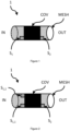
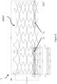
- a tissue stent according to the invention is shown schematically in Figure 1 .
- a tissue stent 1 according to the invention allows for passage of a fluid such as blood, the tissue stent 1 is therefore suited for implantation into the body of a mammal, e.g. composed of biocompatible materials or covered by biocompatible material.
- the tissue stent 1 comprises a body forming said passage from an entry side IN towards an exit side OUT when implanted.
- first sensing portion S 1 and a second sensing portion S 2 is not be held as limiting but any number of sensing portions greater and equal to two may be used.
- more than one sensor portion e.g. S 1,1 and S 1,2 , at like positions, these sensor portions S 1,1 and S 1,2 may allow for more reliability in that a cloth on one sensor portion may not jeopardize the results.
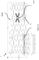
- a third sensor S 3 is place in between the first sensing portion S 1 and the second sensing portion S 2 , e.g. as shown in Figure 3 , more than one pressure gradient may be calculated, e.g. between the first sensing portion S 1 and the second sensing portion S 2 , between the third sensing portion S 3 and the first sensing portion S 1 , between the third sensing portion S 3 and the second sensing portion S 1 , thereby allowing for a finer granularity and allowing for a more precise location information where a blockage may exist.
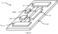
- a sensor portion according to the invention is shown schematically in Figure 6 .
- the tissue stent 1 according to the invention also comprises an inductivity L 1
- the inductivity L 1 is temporarily connected to the energy harvesting and storage portion BAT allowing for energy harvesting. In times the inductivity L 1 is not connected to the energy harvesting and storage portion BAT the inductivity L 1 may be used for one or more other purposes.
- the inductivity L 1 may be temporarily connected to the wireless sending portion TX allowing for sending information. That is, the inductivity L 1 is emitting pulses according to a prescribed scheme representing information of the tissue stent 1.
- the tissue stent 1 allows for measurement of the pressure at the inflow IN of the passage and the exit OUT. Based on both pressure data a pressure difference may be calculated (within the tissue stent or externally) thereby allowing to determine whether the tissue stent is still functional, partially blocked or fully blocked.
- tissue stent according to the invention allows for simplified and reliable controls at lower costs.
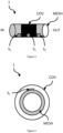
- the Tissue stent according to embodiments of the invention may be covered with a biocompatible respectively bioresistive cover COV, in particular a PTFE-cover.
- Biocompatible may also encompass that the cover COV exhibits certain additional properties as required, e.g. inhibiting ingrowth, releasing drugs, etc.
- This cover COV may be arranged such that a sensing portion S 1 , S 2 ,.. may even be partially covered by the cover COV and may spare the actual pressure sensing area S pressure as can be seen e.g. in figures 1-3 and 5 .
- a tissue stent according to the invention may comprise e.g. 33 cross struts and 10 crowns like the one shown in Figure 8 and 10 .
- the struts in between the crowns are designed such that they are short and flexible in the center region of the tissue stent 1 while being rigid towards the ends IN, OUT of the tissue stent 1.
- the tissue stent 1 may be bend in the center region allowing for flexibility within the tissue while the end portions IN, OUT provide for stability e.g. for placement of the sensing portions S 1 , S 2 .
- the wireless sending portion TX is arranged to harvest energy provided by external electro-magnetical fields.
- the wireless sending portion may use an antenna / wire loop to collect electro-magnetical fields.
- This antenna / wire loop may be the same as used for sending information but it may also be a different antenna / wire loop for this particular purpose only.
- the invention provides for an evaluation unit uC, such as a microcontroller, a microprocessor, an application-specific integrated circuit (ASIC) or a Field Programmable Gate Array (FPGA).
- an evaluation unit uC allows for evaluating sensor data received from the respective sensing portions before sending information.
- the evaluation unit may derive information indicative of the functional conditions of the passage, e.g. a pressure difference / a pressure gradient, before transmitting the information, i.e. the pressure difference / pressure gradient, via the wireless sending portion TX.
- the wireless sending portion TX and the evaluation unit uC may be embodied in a single unit. This combined unit will also be identified as sending portion TX.
- the tissue stent 1 may be arranged such that it may easily deployed via microsurgical devices and or intra-luminal deployment technologies such as stent advancement via a catheter and expansion of the stent 1 at the required location, i.e. the stent 1 is arranged for being expanded during the implantation process. Therefore, the stent 1 may comprise a mesh like supporting body MESH.
- the sensing portions TX and / or the wireless sending portion TX as well as other portions of the sensor portion may be arranged on a flexible supporting layer LAY.
- This supporting layer is preferably flexible and may be a flexible printed circuit board.
- This supporting layer LAY together with all pre-assembled portions may then be arranged at specific positions relative to the supporting body MESH before a cover COV is applied which thereby allows for fixating the supporting layer and at least some of the portions arranged on the supporting layer LAY.
- the production may be streamlined in that pre-assembled sensing portions S 1 , S 2 , ... may be pre-produced on respective supporting layers LAY.
- the supporting layer LAY may allow for some bending of the tissue stent when being delivered such that tissue stent deployment is not detrimentally affected by the provisioning of the sensing portions.
- the supporting layer LAY may comprise a thin flexible polymeric sheet, e.g. made of / comprising polyimid.
- the supporting layer LAY may also be biocompatible respectively bioresistive.
- the wireless sending portion TX is arranged for sending a unique identification ID.
- This ID may be unique with respect to a sensing portion or may be unique with respect to a tissue stent. Whether an ID is provided per stent or per sensing portion is subject to implementation. The purpose of the ID is to clearly identify each tissue stent. Hence, even if a patient is implanted with more than one tissue stent according to the invention, one would still be able to clearly recognize which information is originating from a particular stent.
- some embodiments may comprise a storage portion MEM for storing information indicative of the functional conditions of the passage.
- the information stored may be raw-data of the sensing portions, evaluated data such as obtained by an evaluation unit uC and the information may be stored such that the sensing portion of a particular data is derivable.
- the stored information may be used for additional evaluations either by the evaluation unit uC or by an external unit after the data is sent thereto.
- tissue stent may also allow for some interaction such that particular data may be forwarded.
- the tissue stent 1 according to the invention is therefore particular suitable for the scenario mentioned in the background section, i.e. it may be used within a liver.
- the tissue stent 1 is not a prosthesis for a lumen (intra-luminal prosthesis) but is a stent for tissue. I.e. the channel the stent keeps open is created through a (micro-) surgical invention with the respective tissue. As such the tissue stent allows for a wireless inspection of the passage by providing data indicative of the passage.
- the tissue stent may allow monitoring of pre- and post-hepatic pressure as well as flow properties and therefore allows objectively to control the passage kept open by the tissue stent.
- the tissue stent 1 Since the tissue stent 1 is equipped with an energy harvesting in storage portion BAT, the tissue stent requires no cables. Cables as known from other devices tend to create bridges allowing bacteria and virus entry. Hence eliminating such bridges allows for less complication.
- Sensing portions may be fixed to the supporting body MESH e.g. via electro-spinning process as will be detailed in the following.
- a supporting layer LAY is arranged in between layers of cover COV. I.e. a first layer of cover material is electro-spun onto the body MESH, then the supporting layer as detailed above is applied onto this layer and another layer of cover material is electro-spun onto the covered body MESH and the supporting layer LAY thereby providing for a stable (adhesive) arrangement.
- Such a tissue stent 1 according to the invention may even be crimped towards a delivery system (geode wire, etc.) without harming the sensor portions.
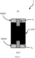
- the sensing portions S 1 , S 2 may be arranged on the inside (not shown) or the outside of the supporting body MESH.
- the pressure sensor S pressure of the sensing portion S 1 , S 2 , ... are able to detect a respective pressure at the location within the passage.
- the pressure sensor is in fluidic communication with the passage. I.e. even the pressure sensor may be covered if the cover COV does allow for sensing pressure below the cover COV. Therefore, the production is inexpensive as stripping or shielding of the cover COV at the pressure sensor S pressure is obviated.
- the supporting layer LAY as can be seen in figures 5 , 6 , 8 and 10 is preferably an elongated small strip which is provided preferably in parallel to an axis of the passage on top of the supporting body MESH.
- the supporting structure may provide for added flexibility by providing portions of even more reduced size such that more bending is allowed in certain regions thereby adding for the flexibility of the overall tissue stent 1.
- the supporting layer LAY of a sensor portion may comprise one or more securing means such as holes allowing for securing the supporting layer LAY towards the supporting body either in addition to or as an alternative to an adhesive layer of the cover COV ontop of the supporting body MESH as described before.
- the securing means allows for suturing the supporting layer towards the supporting body MESH.
- the supporting body MESH may provide for securing means allowing for securing the end portions of the tissue sent 1 towards vessels and/or tissue.
- the supporting body MESH may provide for holes allowing for suturing the tissue stent 1 towards vessels and/or tissue.
- the supporting layer LAY is preferably arranged substantially parallel with respect to an axis formed by the passage of the tissue stent 1. Thereby (as shown in Figures 8 and 10 ) the supporting layer LAY does not inhibit compression / decompression of the tissue stent 1 for delivery.
- the supporting layer LAY may be fixed to the mesh MESH at one or more locations, whereby fixing may also encompass flexible material to accommodate displacement of fixing points of the mesh when being compressed / decompressed.
- the supporting layer LAY may provide for a different shape as will be also further detailed with respect to Figures 10 and 11 .
- the components of the sensing portion are miniaturized.
- SMD surface mounted devices
- some of the functionality, e.g. the evaluation unit and / or the memory and / or the transmission unit and / or the energy harvesting unit may be integrated into a chip or a chip arrangement or in a system in package (SIP) arrangement.
- SIP system in package
- SMD inductivities may be used for the energy harvesting and storage portion BAT.
- bare dies i.e. electronic elements without their typical housing, may be used allowing for a reduced height and increased flexibility. This is possible as the covering COV is protecting the dies from any harmful impact.
- the electronics of the sensing portions may also be covered by another polymer or a silicone type covering.
- the sensing portions may allow for relative high voltages, e.g. provided by a charge pump and/or by means of inductivities.
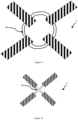
- Energy harvesting may be performed e.g. by arranging one or more inductivities L1, L2. Preferably a plurality of inductivities is provided.
- the directions of main sensitivity of the multiple inductivities are arranged such that the directions are not in parallel (but preferably orthogonal to each other) to ensure that irrespective of the main direction of energy provided by a "receiving unit" (a maximum of) energy may be harvested.
- up- and/or down conversion of the voltage stored in said high-C capacitors may be provided to offer one or more constant voltage towards electronic components of the tissue stent necessitating such constant voltage.
- High voltages may also be beneficially used for communication by the tissue stent 1.
- the data communication may be provided by high voltage pulses having a small pulse width of e.g. 1 ⁇ s.
- the duration is selected such that inductivity L 1 , L 2 is charged (near to) maximum energy.
- the falling edge is such that for a sufficient long time a high voltage is provided at the inductivity.
- the high voltage may be around and even above 100 V. After decline of the voltage the next pulse is transmitted.
- the electronics E or at least parts thereof may be produced in a Highvoltage-CMOS process.
- the system design allows for a coding of the data / information for added reliability of the transmission.
- Such coding may encompass error detection such as cyclic redundancy checks and error correction such as forward error correction schemes.
- error correction such as forward error correction schemes.
- higher coding schemes such as turbo coding is thereby not excluded.
- such issues are subject to higher layers of a respective data transmission protocol.
- the system may even allow for training sequences and a coding negotiation of the wireless sending portion TX towards a data receiving unit.
- the receiving unit may even be arranged to instigate retransmission of data / information upon detecting errors and may even instruct a different, e.g. a more reliable, transmission scheme.
- the receiving portion may instruct the tissue stent 1 to retransmit some or all data with a higher error detection property. Obviously, subject to the error detection scheme this may adaptively escalated or de-escalated as needed to accommodate a respective channel.
- the impedance of the wireless energy transmission towards the energy harvesting BAT may be such that a control circuit controls MOS-varactors that a maximum voltage in the energy harvesting section (resonant circuit) is achieved.
- a control circuit controls MOS-varactors that a maximum voltage in the energy harvesting section (resonant circuit) is achieved.
- the tissue stent 1 may signal this situation (or may even indicate a norm indicative of the excess) such that the "data receiving unit" may reduce its transmission power.
- the harvested energy may allow for autonomous operation of the tissues stent for long periods. That ist, even though the patient is out of reach of a receiving unit, the harvested energy allows for autonomous operation of the stent for time periods in the range of minutes, to hours and even several days.
- data transmission from the receiving unit towards the tissue stent may by repeated within a multiple period of the resonant period of the receiving resonant circuit. In doing so, energy harvesting is enabled while ensuring reception of the data.
- Data measured by sensors may be stored in a non-volatile memory. Storage may be bitwise. To minimize storage it is preferred to store deviations of following values with respect to an initial stored value / threshold instead of absolute values to better utilize storage resources.
- the tissue stent 1 may offer a plurality of sensors it is preferred that the signals may be multiplexed. That is the sensors may be powered and measured individually. The measurements may be performed in a periodic manner or upon certain events. A particular sequence of measurements may also be foreseen. That is, the retrieval of sensor data is extremely flexible. In a flexible arrangement care must be taken to store sensor data appropriately (as well as to communicate sensor data appropriately) such that the sensor data may still be attributed towards a specific sensor. This also allows for reduced energy consumption.
- the sending period of the tissue stents 1 may be triggered by a targeted request to a particular tissue stent or by a different time basis provided for each tissue stent.
- the time basis is determined by the start of operation of a respective tissue stent whereby the time frame used for communication is rather small compared to the interval between consecutive time frames. That is the likelihood of a collision of data is minimized.
- the energy harvesting and storage portion BAT may allow for inductive coupling. Therefore, the an energy harvesting and storage portion BAT may comprise as shown in Figure 7 or 9 a plurality of inductivities L 1 , L 2 arranged within resonant circuits. It may even be foreseen that energy transmission towards the energy harvesting and storage portion BAT is performed will transmitting data from the "receiving unit" outside the patient towards the sensing portion(s) of a tissue stent 1 inside the patient.
- the circuitry of an embodiment of the sensing portions may even allow for adaption of the transmitted power, e.g. by measuring a voltage attained within the sensing portion by means of the energy harvesting and storage portion BAT and if the voltage attains or exceeds a certain threshold, it is indicated towards the "receiving unit" that the power transmitted towards the an energy harvesting and storage portion BAT may be reduced.
- the energy harvesting and storage portion BAT as shown in figures 7 and 9 may comprise one or more capacities, in particular having high capacity.
- the storage capacity may be increased by usage of capacities in parallel.
- the energy provided by the energy harvesting and storage portion BAT is sufficient that the sensing portion may operate autonomously for a certain period of time allowing for repowering the energy harvesting and storage portion BAT in intervals, thereby allowing a patient to perform a normal life through the majority of time.
- the sensing portion may comprise a unit for up and/or down conversion such that the required voltage by the other units may be provided as necessary in a flexible manner.
- each coil / inductivity L 1 andL 2 has a specific purpose.
- a coil / inductivity L 1 of the energy harvesting BAT as a sending coil / inductivity it is however necessary to provide an energy storage which may be embodied by a capacitor C storage as indicated in Figure 9 .
- the memory MEM shown in Figure 6 may be of a volatile or a non-volatile type.
- the memory MEM may comprise an EE(P)ROM or Flash memory. Storing of data allows for a packetized transfer of a plurality of data towards a receiving unit thereby increasing energy efficiency.
- the storage of data as well as the transfer of data may be adapted to gain further efficiency e.g. by storing only deviation with respect to a preceding value or with respect to an initial value.
- the tissue stent may be shrinked, e.g. by crimping, for delivery.
- the electronics E e.g. as shown in figure 7 and 9
- the electronics E e.g. as shown in figure 7 and 9
- parts of said at least two sensing portions S 1 , S 2 , said energy harvesting and storage portion BAT, and said wireless sending portion TX are rather brittle and/or inflexible, it is preferred to arrange / fix such parts substantially in parallel to a portion of the mesh MESH such that they may be moved substantially with the mesh portion during expansion / compression.
- Mesh portions used for arrangement / fixing of portions of the electronics E are preferably inflexible compared to portions of the mesh acting as knots (crowns) of the mesh MESH.
- said parts are fixedly connected to said respective portion of the mesh MESH each at one particular location.
- fixation of each art towards a respective portion may by sufficient, it may also be provided that more than one fixation location is present. In that case - to allow shrinking / expanding of the respective portion of the mesh MESH, the additional location allows for movement in parallel to the respective portion of the mesh MESH during expansion / compression. To enable such operation the fixation may be movable with respect to the mesh portion and/or the fixation material may offer flexibility.
- the respective electrical connections across portions are preferably flexible, e.g. wires W, so that they may bend when the tissue stent is compressed / expanded / delivered.
- the invention may use any kind of near field communication system. I.e. the invention may even allow a patient to read out / energize his or her stent via a near field communication enabled home device, e.g. a mobile phone having a NFC interface, as an exemplary receiving unit.
- a near field communication enabled home device e.g. a mobile phone having a NFC interface
- the data received indicative of the passage may then be processed and/or stored and/or forwarded towards a medical center for further analysis respectively generation of warning messages in case of a suspected blockage of the passage which might necessitate a re-intervention.
Landscapes
- Health & Medical Sciences (AREA)
- Life Sciences & Earth Sciences (AREA)
- Engineering & Computer Science (AREA)
- Biomedical Technology (AREA)
- Public Health (AREA)
- Heart & Thoracic Surgery (AREA)
- Animal Behavior & Ethology (AREA)
- General Health & Medical Sciences (AREA)
- Veterinary Medicine (AREA)
- Physics & Mathematics (AREA)
- Vascular Medicine (AREA)
- Pathology (AREA)
- Biophysics (AREA)
- Medical Informatics (AREA)
- Molecular Biology (AREA)
- Surgery (AREA)
- Cardiology (AREA)
- Physiology (AREA)
- Signal Processing (AREA)
- Oral & Maxillofacial Surgery (AREA)
- Transplantation (AREA)
- Neurosurgery (AREA)
- Power Engineering (AREA)
- Artificial Intelligence (AREA)
- Computer Vision & Pattern Recognition (AREA)
- Psychiatry (AREA)
- Computer Networks & Wireless Communication (AREA)
- Optics & Photonics (AREA)
- Prostheses (AREA)
Claims (22)
- Gewebestent (1) zur Ermöglichung des Durchgangs eines Fluids, wobei der Gewebestent (1) zur Implantation in den Körper eines Säugetiers geeignet ist, wobei der Gewebestent (1) umfasst:• einen Körper (MESH), der den Durchgang von einer Eingangsseite (IN) zu einer Ausgangsseite (OUT) bildet, wenn er implantiert ist,• einen Abschnitt zur Energiegewinnungs und -speicherung (BAT),• eine Induktivität (L1),
dadurch gekennzeichnet, dass der Gewebestent ferner umfasst• mindestens zwei Sensorabschnitte (S1, S2), wobei ein erster Sensorabschnitt (S1) in der Nähe der Eingangsseite (IN) und ein zweiter Sensorabschnitt (S2) in der Nähe der Ausgangsseite (OUT) angeordnet ist, wobei der erste Sensorabschnitt (S1) und der zweite Sensorabschnitt (S2) Drucksensoren (SDruck) sind,• einen drahtlosen Sendeabschnitt (TX) zum Senden von Informationen, die den Funktionszustand des Durchgangs anzeigt,• wobei die mindestens zwei Sensorabschnitte (S1, S2) und der drahtlose Sendeabschnitt (TX) über den Energiegewinnungs- und -speicherabschnitt (BAT) mit Energie versorgt werden,• wobei die Induktivität (L1) vorübergehend mit dem Energiegewinnungs- und - speicherabschnitt (BAT) verbunden ist, was eine Energiegewinnung ermöglicht, und wobei die Induktivität (L1), wenn sie nicht mit dem Energiegewinnungs- und -speicherabschnitt (BAT) verbunden ist, temporär mit dem drahtlosen Sendeabschnitt (TX) verbunden ist, um das Senden von Informationen zu ermöglichen. - Gewebestent nach Anspruch 1, wobei der Gewebestent mit einer biokompatiblen Abdeckung (COV), insbesondere einer PTFE-Abdeckung, bedeckt ist.
- Gewebestent nach Anspruch 2, wobei Abschnitte der Sensorabschnitte (S1, S2) innerhalb der biokompatiblen Abdeckung (COV) angeordnet sind.
- Gewebestent nach einem der Ansprüche 1 bis 3, wobei der drahtlos Sendeabschnitt (TX) so angeordnet ist, dass er von externen elektromagnetischen Feldern bereitgestellte Energie gewinnt.
- Gewebestent nach einem der Ansprüche 1 bis 4, wobei der drahtlose Sendeabschnitt (TX) ferner so angeordnet ist, dass er Sensordaten auswertet, die von dem ersten und zweiten Sensorabschnitt (S1, S2) empfangen werden, bevor er Informationen sendet, die den Funktionszustand des Durchgangs anzeigen.
- Gewebestent nach einem der Ansprüche 1 bis 5, wobei der Gewebestent (1) so angeordnet ist, dass er während des Implantationsprozesses ausgedehnt wird.
- Gewebestent nach einem der Ansprüche 1 bis 6, wobei die Sensorabschnitte (TX) und/oder der drahtlose Sendeabschnitt (TX) auf einer flexiblen Trägerschicht (LAY) angeordnet sind.
- Gewebestent nach einem der Ansprüche 1 bis 7, wobei der drahtlose Sendeabschnitt (TX) zum Senden einer eindeutigen Kennung (ID) angeordnet ist.
- Gewebestent nach einem der Ansprüche 1 bis 8, ferner umfassend einen Speicherabschnitt (MEM) zum Speichern von Informationen, die den Funktionszustand des Durchgangs anzeigen.
- Gewebestent nach einem der Ansprüche 1 bis 9, wobei der drahtlose Sendeabschnitt (TX) einem Nahfeldkommunikationsstandard entspricht.
- Gewebestent nach einem der Ansprüche 1 bis 10, wobei zumindest Abschnitte der mindestens zwei Sensorabschnitte (S1, S2), des Energiegewinnungs- und - speicherabschnitts (BAT) und des drahtlosen Sendeabschnitts (TX) auf verschiedenen Abschnitten angeordnet sind, wobei jeder Abschnitt im Wesentlichen parallel zu einem Abschnitt des Netzes (MESH) angeordnet ist, so dass sie während der Ausdehnung/Kompression im Wesentlichen mit dem jeweiligen Netzabschnitt bewegt werden können.
- Gewebestent nach Anspruch 11, wobei die Abschnitte durch flexible Drähte miteinander verbunden sind.
- Gewebestent nach Anspruch 11 oder 12, wobei die Abschnitte mit dem jeweiligen Abschnitt des Netzes (MESH) jeweils an einer bestimmten Stelle fest verbunden sind.
- Gewebestent nach Anspruch 13, wobei die Abschnitte mit dem jeweiligen Abschnitt des Gewebes (MESH) jeweils an einer anderen bestimmten Stelle verbunden sind, wobei die Verbindung eine Bewegung parallel zu dem jeweiligen Abschnitt des Gewebes (MESH) während der Ausdehnung/Kompression ermöglicht.
- Gewebestent nach einem der Ansprüche 1 bis 14, wobei im Falle einer Störung der Kommunikation der drahtlose Sendeabschnitt (TX) so angepasst ist, dass er die Kommunikation unter Verwendung eines anderen Codierungsschemas, das eine Fehlerkorrektur ermöglicht, anpassen kann.
- Gewebestent nach einem der Ansprüche 1 bis 15, wobei der Energiegewinnungs- und - speicherabschnitt (BAT) einen oder mehrere Kondensatoren mit hoher Kapazität umfasst.
- Gewebestent nach einem der Ansprüche 1 bis 16, wobei ein dritter Sensor S3 zwischen dem ersten Sensorabschnitt S1 und dem zweiten Sensorabschnitt S2 vorgesehen ist, wodurch mehr als ein Druckgradient berechnet werden kann, wodurch eine feinere Granularität und eine genauere Ortsangabe ermöglicht wird, wo eine Blockade vorhanden sein kann.
- Gewebestent nach einem der Ansprüche 1 bis 17, wobei der Stützkörper (MESH) Befestigungsmittel aufweist, die es ermöglichen, dass ein Endabschnitt des Gewebestents (1) an Gefäßen und/oder Gewebe befestigt wird.
- Gewebestent nach einem der Ansprüche 1 bis 18, wobei eine weitere Induktivität (L2) vorgesehen ist, wobei die Richtungen der Hauptempfindlichkeit der Induktivitäten (L1, L2) so angeordnet sind, dass die Richtungen nicht parallel sind.
- Gewebestent nach einem der Ansprüche 1 bis 19, wobei der Gewebestent ferner einen Steuerschaltkreis und MOS-Varaktoren umfasst, wobei der Steuerschaltkreis so angeordnet ist, dass er die MOS-Varaktoren so steuert, dass eine maximale Spannung in dem Energiegewinnungs- und -speicherabschnitt (BAT) erreicht wird, wobei, falls die Spannung einen bestimmten Schwellenwert überschreitet, der Gewebestent 1 diese Situation signalisieren kann, so dass eine externe Einheit, die eine externe Einheit, die Informationen über den Funktionszustand des Durchgangs empfängt, ihre Sendeleistung reduzieren kann.
- Gewebestent nach einem der Ansprüche 1 bis 20, wobei die Signale der mindestens zwei Sensorabschnitte (S1, S2) multiplexiert werden.
- Gewebestent nach einem der Ansprüche 1 bis 21, wobei der erste Sensorabschnitt eine Einheit zur Aufwärts- und/oder Abwärtswandlung umfasst, so dass die erforderliche Spannung von den anderen Einheiten je nach Bedarf auf flexible Weise bereitgestellt werden kann.
Applications Claiming Priority (2)
| Application Number | Priority Date | Filing Date | Title |
|---|---|---|---|
| LU93035A LU93035B1 (en) | 2016-04-20 | 2016-04-20 | Tissue Stent |
| PCT/EP2017/059442 WO2017182588A1 (en) | 2016-04-20 | 2017-04-20 | Tissue stent |
Publications (3)
| Publication Number | Publication Date |
|---|---|
| EP3445294A1 EP3445294A1 (de) | 2019-02-27 |
| EP3445294B1 true EP3445294B1 (de) | 2024-12-04 |
| EP3445294C0 EP3445294C0 (de) | 2024-12-04 |
Family
ID=55971166
Family Applications (1)
| Application Number | Title | Priority Date | Filing Date |
|---|---|---|---|
| EP17720054.0A Active EP3445294B1 (de) | 2016-04-20 | 2017-04-20 | Gewebestent |
Country Status (3)
| Country | Link |
|---|---|
| EP (1) | EP3445294B1 (de) |
| LU (1) | LU93035B1 (de) |
| WO (1) | WO2017182588A1 (de) |
Family Cites Families (5)
| Publication number | Priority date | Publication date | Assignee | Title |
|---|---|---|---|---|
| US20020183628A1 (en) * | 2001-06-05 | 2002-12-05 | Sanford Reich | Pressure sensing endograft |
| EP2043512A2 (de) * | 2006-07-21 | 2009-04-08 | Cardiac Pacemakers, Inc. | System und verfahren zur adressierung implantierbarer vorrichtungen |
| FR2905260B1 (fr) * | 2006-09-04 | 2010-06-04 | Univ Paris Curie | Endoprothese et procede de fabrication d'une endoprothese. |
| WO2013164829A1 (en) * | 2012-05-02 | 2013-11-07 | Enopace Biomedical Ltd. | Wireless endovascular stent-based electrodes |
| FR3026631B1 (fr) * | 2014-10-03 | 2016-12-09 | Ecole Polytech | Dispositif medical implantable muni de capteurs |
-
2016
- 2016-04-20 LU LU93035A patent/LU93035B1/en active IP Right Grant
-
2017
- 2017-04-20 EP EP17720054.0A patent/EP3445294B1/de active Active
- 2017-04-20 WO PCT/EP2017/059442 patent/WO2017182588A1/en not_active Ceased
Also Published As
| Publication number | Publication date |
|---|---|
| EP3445294A1 (de) | 2019-02-27 |
| EP3445294C0 (de) | 2024-12-04 |
| LU93035B1 (en) | 2017-10-27 |
| WO2017182588A1 (en) | 2017-10-26 |
Similar Documents
| Publication | Publication Date | Title |
|---|---|---|
| US12390331B2 (en) | Implantable coaptation assist devices with sensors and associated systems and methods | |
| JP7241405B2 (ja) | 患者の血管及び体液状態をモニタリングするための無線共振回路ならびに可変インダクタンス血管インプラント、ならびにそれを利用するシステム及び方法 | |
| AU2020372841B2 (en) | Sensor integration in cardiac implant devices | |
| US20210401418A1 (en) | Occluder with self-powered sensors | |
| KR102358589B1 (ko) | 심부전 모니터링을 위한 이식가능 장치 및 관련 방법 | |
| US8939905B2 (en) | Antenna structures for implantable medical devices | |
| US7711434B2 (en) | Wireless intravascular medical device with a double helical antenna assembly | |
| US20230218180A1 (en) | Monitoring systems and devices for heart implants | |
| CN112512408B (zh) | 无线谐振电路和可变电感血管监测植入物及其锚定结构 | |
| CN101856222A (zh) | 植入式无线电子检测装置 | |
| JP2019509116A (ja) | 一体化されたセンサおよび送信機を備える弁インプラント | |
| WO2012015954A1 (en) | Transvascular wireless sensor system | |
| US20260026695A1 (en) | Monitoring of endoleaks | |
| EP3445294B1 (de) | Gewebestent | |
| John et al. | Telemetric system for monitoring of endoleak in abdominal aorta aneurysm using multiple pressure sensors integrated on a stent graft | |
| US20240138688A1 (en) | Implantable sensor for measuring and monitoring intravascular pressure, system comprising said sensor and method for operating thereof | |
| US20140018643A1 (en) | Self-contained system suitable for being inserted into an anatomical cavity | |
| WO2025212628A1 (en) | Method and device for cardiac pressure sensing using an active implantable device and near field communication | |
| EP3498152A1 (de) | Implantatvorrichtung zur überwachung im körper |
Legal Events
| Date | Code | Title | Description |
|---|---|---|---|
| STAA | Information on the status of an ep patent application or granted ep patent |
Free format text: STATUS: UNKNOWN |
|
| STAA | Information on the status of an ep patent application or granted ep patent |
Free format text: STATUS: THE INTERNATIONAL PUBLICATION HAS BEEN MADE |
|
| PUAI | Public reference made under article 153(3) epc to a published international application that has entered the european phase |
Free format text: ORIGINAL CODE: 0009012 |
|
| STAA | Information on the status of an ep patent application or granted ep patent |
Free format text: STATUS: REQUEST FOR EXAMINATION WAS MADE |
|
| 17P | Request for examination filed |
Effective date: 20181102 |
|
| AK | Designated contracting states |
Kind code of ref document: A1 Designated state(s): AL AT BE BG CH CY CZ DE DK EE ES FI FR GB GR HR HU IE IS IT LI LT LU LV MC MK MT NL NO PL PT RO RS SE SI SK SM TR |
|
| AX | Request for extension of the european patent |
Extension state: BA ME |
|
| RIN1 | Information on inventor provided before grant (corrected) |
Inventor name: RANJAN, RAJEEV Inventor name: BIBIN, JOHN Inventor name: ADAM, GERHARD Inventor name: KOOPS, ANDREAS Inventor name: BUHK, JAN-HENDRIK Inventor name: WOLDT, GREGOR Inventor name: SCHROEDER, DIETMAR Inventor name: BRAUNSCHWEIG, MARKUS Inventor name: KRAUTSCHNEIDER, WOLFGANG Inventor name: SPINK, CLEMENS |
|
| DAV | Request for validation of the european patent (deleted) | ||
| DAX | Request for extension of the european patent (deleted) | ||
| STAA | Information on the status of an ep patent application or granted ep patent |
Free format text: STATUS: EXAMINATION IS IN PROGRESS |
|
| 17Q | First examination report despatched |
Effective date: 20240611 |
|
| GRAP | Despatch of communication of intention to grant a patent |
Free format text: ORIGINAL CODE: EPIDOSNIGR1 |
|
| STAA | Information on the status of an ep patent application or granted ep patent |
Free format text: STATUS: GRANT OF PATENT IS INTENDED |
|
| INTG | Intention to grant announced |
Effective date: 20240730 |
|
| GRAS | Grant fee paid |
Free format text: ORIGINAL CODE: EPIDOSNIGR3 |
|
| GRAA | (expected) grant |
Free format text: ORIGINAL CODE: 0009210 |
|
| STAA | Information on the status of an ep patent application or granted ep patent |
Free format text: STATUS: THE PATENT HAS BEEN GRANTED |
|
| AK | Designated contracting states |
Kind code of ref document: B1 Designated state(s): AL AT BE BG CH CY CZ DE DK EE ES FI FR GB GR HR HU IE IS IT LI LT LU LV MC MK MT NL NO PL PT RO RS SE SI SK SM TR |
|
| REG | Reference to a national code |
Ref country code: GB Ref legal event code: FG4D |
|
| REG | Reference to a national code |
Ref country code: CH Ref legal event code: EP |
|
| REG | Reference to a national code |
Ref country code: DE Ref legal event code: R096 Ref document number: 602017086524 Country of ref document: DE |
|
| REG | Reference to a national code |
Ref country code: IE Ref legal event code: FG4D |
|
| RAP2 | Party data changed (patent owner data changed or rights of a patent transferred) |
Owner name: FIRST SENSOR MICROELECTRONIC PACKAGING GMBH Owner name: TECHNISCHE UNIVERSITAET HAMBURG-HARBURG |
|
| U01 | Request for unitary effect filed |
Effective date: 20241204 |
|
| RAP2 | Party data changed (patent owner data changed or rights of a patent transferred) |
Owner name: FIRST SENSOR AG Owner name: TECHNISCHE UNIVERSITAET HAMBURG-HARBURG |
|
| U07 | Unitary effect registered |
Designated state(s): AT BE BG DE DK EE FI FR IT LT LU LV MT NL PT RO SE SI Effective date: 20241211 |
|
| PG25 | Lapsed in a contracting state [announced via postgrant information from national office to epo] |
Ref country code: HR Free format text: LAPSE BECAUSE OF FAILURE TO SUBMIT A TRANSLATION OF THE DESCRIPTION OR TO PAY THE FEE WITHIN THE PRESCRIBED TIME-LIMIT Effective date: 20241204 |
|
| PG25 | Lapsed in a contracting state [announced via postgrant information from national office to epo] |
Ref country code: ES Free format text: LAPSE BECAUSE OF FAILURE TO SUBMIT A TRANSLATION OF THE DESCRIPTION OR TO PAY THE FEE WITHIN THE PRESCRIBED TIME-LIMIT Effective date: 20241204 |
|
| PG25 | Lapsed in a contracting state [announced via postgrant information from national office to epo] |
Ref country code: NO Free format text: LAPSE BECAUSE OF FAILURE TO SUBMIT A TRANSLATION OF THE DESCRIPTION OR TO PAY THE FEE WITHIN THE PRESCRIBED TIME-LIMIT Effective date: 20250304 |
|
| PG25 | Lapsed in a contracting state [announced via postgrant information from national office to epo] |
Ref country code: GR Free format text: LAPSE BECAUSE OF FAILURE TO SUBMIT A TRANSLATION OF THE DESCRIPTION OR TO PAY THE FEE WITHIN THE PRESCRIBED TIME-LIMIT Effective date: 20250305 |
|
| PGFP | Annual fee paid to national office [announced via postgrant information from national office to epo] |
Ref country code: GB Payment date: 20250313 Year of fee payment: 9 |
|
| PG25 | Lapsed in a contracting state [announced via postgrant information from national office to epo] |
Ref country code: RS Free format text: LAPSE BECAUSE OF FAILURE TO SUBMIT A TRANSLATION OF THE DESCRIPTION OR TO PAY THE FEE WITHIN THE PRESCRIBED TIME-LIMIT Effective date: 20250304 |
|
| U20 | Renewal fee for the european patent with unitary effect paid |
Year of fee payment: 9 Effective date: 20250328 |
|
| PG25 | Lapsed in a contracting state [announced via postgrant information from national office to epo] |
Ref country code: SM Free format text: LAPSE BECAUSE OF FAILURE TO SUBMIT A TRANSLATION OF THE DESCRIPTION OR TO PAY THE FEE WITHIN THE PRESCRIBED TIME-LIMIT Effective date: 20241204 |
|
| PG25 | Lapsed in a contracting state [announced via postgrant information from national office to epo] |
Ref country code: PL Free format text: LAPSE BECAUSE OF FAILURE TO SUBMIT A TRANSLATION OF THE DESCRIPTION OR TO PAY THE FEE WITHIN THE PRESCRIBED TIME-LIMIT Effective date: 20241204 |
|
| PG25 | Lapsed in a contracting state [announced via postgrant information from national office to epo] |
Ref country code: IS Free format text: LAPSE BECAUSE OF FAILURE TO SUBMIT A TRANSLATION OF THE DESCRIPTION OR TO PAY THE FEE WITHIN THE PRESCRIBED TIME-LIMIT Effective date: 20250404 |
|
| PG25 | Lapsed in a contracting state [announced via postgrant information from national office to epo] |
Ref country code: SK Free format text: LAPSE BECAUSE OF FAILURE TO SUBMIT A TRANSLATION OF THE DESCRIPTION OR TO PAY THE FEE WITHIN THE PRESCRIBED TIME-LIMIT Effective date: 20241204 |
|
| PG25 | Lapsed in a contracting state [announced via postgrant information from national office to epo] |
Ref country code: CZ Free format text: LAPSE BECAUSE OF FAILURE TO SUBMIT A TRANSLATION OF THE DESCRIPTION OR TO PAY THE FEE WITHIN THE PRESCRIBED TIME-LIMIT Effective date: 20241204 |
|
| PLBE | No opposition filed within time limit |
Free format text: ORIGINAL CODE: 0009261 |
|
| STAA | Information on the status of an ep patent application or granted ep patent |
Free format text: STATUS: NO OPPOSITION FILED WITHIN TIME LIMIT |
|
| REG | Reference to a national code |
Ref country code: CH Ref legal event code: L10 Free format text: ST27 STATUS EVENT CODE: U-0-0-L10-L00 (AS PROVIDED BY THE NATIONAL OFFICE) Effective date: 20251015 |
|
| 26N | No opposition filed |
Effective date: 20250905 |
|
| REG | Reference to a national code |
Ref country code: CH Ref legal event code: H13 Free format text: ST27 STATUS EVENT CODE: U-0-0-H10-H13 (AS PROVIDED BY THE NATIONAL OFFICE) Effective date: 20251125 |
|
| PG25 | Lapsed in a contracting state [announced via postgrant information from national office to epo] |
Ref country code: MC Free format text: LAPSE BECAUSE OF FAILURE TO SUBMIT A TRANSLATION OF THE DESCRIPTION OR TO PAY THE FEE WITHIN THE PRESCRIBED TIME-LIMIT Effective date: 20241204 |
|
| PG25 | Lapsed in a contracting state [announced via postgrant information from national office to epo] |
Ref country code: CH Free format text: LAPSE BECAUSE OF NON-PAYMENT OF DUE FEES Effective date: 20250430 |
|
| REG | Reference to a national code |
Ref country code: GB Ref legal event code: 732E Free format text: REGISTERED BETWEEN 20260108 AND 20260114 |