EP3445293B1 - Stress relieving device - Google Patents
Stress relieving device Download PDFInfo
- Publication number
- EP3445293B1 EP3445293B1 EP17722208.0A EP17722208A EP3445293B1 EP 3445293 B1 EP3445293 B1 EP 3445293B1 EP 17722208 A EP17722208 A EP 17722208A EP 3445293 B1 EP3445293 B1 EP 3445293B1
- Authority
- EP
- European Patent Office
- Prior art keywords
- tissue
- port
- shape
- setting
- interior space
- Prior art date
- Legal status (The legal status is an assumption and is not a legal conclusion. Google has not performed a legal analysis and makes no representation as to the accuracy of the status listed.)
- Not-in-force
Links
Images



Classifications
-
- A—HUMAN NECESSITIES
- A61—MEDICAL OR VETERINARY SCIENCE; HYGIENE
- A61F—FILTERS IMPLANTABLE INTO BLOOD VESSELS; PROSTHESES; DEVICES PROVIDING PATENCY TO, OR PREVENTING COLLAPSING OF, TUBULAR STRUCTURES OF THE BODY, e.g. STENTS; ORTHOPAEDIC, NURSING OR CONTRACEPTIVE DEVICES; FOMENTATION; TREATMENT OR PROTECTION OF EYES OR EARS; BANDAGES, DRESSINGS OR ABSORBENT PADS; FIRST-AID KITS
- A61F2/00—Filters implantable into blood vessels; Prostheses, i.e. artificial substitutes or replacements for parts of the body; Appliances for connecting them with the body; Devices providing patency to, or preventing collapsing of, tubular structures of the body, e.g. stents
- A61F2/50—Prostheses not implantable in the body
- A61F2/52—Mammary prostheses
-
- A—HUMAN NECESSITIES
- A61—MEDICAL OR VETERINARY SCIENCE; HYGIENE
- A61H—PHYSICAL THERAPY APPARATUS, e.g. DEVICES FOR LOCATING OR STIMULATING REFLEX POINTS IN THE BODY; ARTIFICIAL RESPIRATION; MASSAGE; BATHING DEVICES FOR SPECIAL THERAPEUTIC OR HYGIENIC PURPOSES OR SPECIFIC PARTS OF THE BODY
- A61H9/00—Pneumatic or hydraulic massage
- A61H9/005—Pneumatic massage
- A61H9/0057—Suction
-
- A—HUMAN NECESSITIES
- A61—MEDICAL OR VETERINARY SCIENCE; HYGIENE
- A61F—FILTERS IMPLANTABLE INTO BLOOD VESSELS; PROSTHESES; DEVICES PROVIDING PATENCY TO, OR PREVENTING COLLAPSING OF, TUBULAR STRUCTURES OF THE BODY, e.g. STENTS; ORTHOPAEDIC, NURSING OR CONTRACEPTIVE DEVICES; FOMENTATION; TREATMENT OR PROTECTION OF EYES OR EARS; BANDAGES, DRESSINGS OR ABSORBENT PADS; FIRST-AID KITS
- A61F5/00—Orthopaedic methods or devices for non-surgical treatment of bones or joints; Nursing devices ; Anti-rape devices
- A61F5/01—Orthopaedic devices, e.g. long-term immobilising or pressure directing devices for treating broken or deformed bones such as splints, casts or braces
- A61F5/04—Devices for stretching or reducing fractured limbs; Devices for distractions; Splints
- A61F5/05—Devices for stretching or reducing fractured limbs; Devices for distractions; Splints for immobilising
- A61F5/058—Splints
- A61F5/05833—Splints rigidified by vacuum evacuation
-
- A—HUMAN NECESSITIES
- A61—MEDICAL OR VETERINARY SCIENCE; HYGIENE
- A61F—FILTERS IMPLANTABLE INTO BLOOD VESSELS; PROSTHESES; DEVICES PROVIDING PATENCY TO, OR PREVENTING COLLAPSING OF, TUBULAR STRUCTURES OF THE BODY, e.g. STENTS; ORTHOPAEDIC, NURSING OR CONTRACEPTIVE DEVICES; FOMENTATION; TREATMENT OR PROTECTION OF EYES OR EARS; BANDAGES, DRESSINGS OR ABSORBENT PADS; FIRST-AID KITS
- A61F2/00—Filters implantable into blood vessels; Prostheses, i.e. artificial substitutes or replacements for parts of the body; Appliances for connecting them with the body; Devices providing patency to, or preventing collapsing of, tubular structures of the body, e.g. stents
- A61F2/50—Prostheses not implantable in the body
- A61F2002/501—Prostheses not implantable in the body having an inflatable pocket filled with fluid, i.e. liquid or gas
- A61F2002/5015—Prostheses not implantable in the body having an inflatable pocket filled with fluid, i.e. liquid or gas hardenable fluid, e.g. curable in-situ or cold-hardening casting substance
-
- A—HUMAN NECESSITIES
- A61—MEDICAL OR VETERINARY SCIENCE; HYGIENE
- A61H—PHYSICAL THERAPY APPARATUS, e.g. DEVICES FOR LOCATING OR STIMULATING REFLEX POINTS IN THE BODY; ARTIFICIAL RESPIRATION; MASSAGE; BATHING DEVICES FOR SPECIAL THERAPEUTIC OR HYGIENIC PURPOSES OR SPECIFIC PARTS OF THE BODY
- A61H2205/00—Devices for specific parts of the body
- A61H2205/08—Trunk
- A61H2205/082—Breasts
Definitions
- the present disclosure relates generally to devices for treating an anatomical region near a surgical site according to claim 1, and a method of setting the shape of such a device according to claim 8.
- Vascularization of muscle, tissue, or skin relies on strong blood flow to the region. If breast tissue after surgery is unsupported or improperly supported during healing, blood flow to the tissue can be reduced.
- Breast implants tend to be relatively heavy, and implants placed during surgery can weigh on tissue that is undergoing recovery. Surgical outcomes can be improved if stresses on healing tissue can be reduced.
- healing of other surgical sites can be adversely affected if the site is insufficiently supported.
- healing of surgical incisions after reconstruction or augmentation of breast tissue, or other surgical sites can be slowed by tension on the tissues and the surgical incision site.
- current systems to support breast tissue can place undue pressure or friction directly on the site of the incision, potentially leading to adverse outcomes such as infection or dehiscence.
- US2004/073152 A1 discloses a device according to the preamble of claim 1 and discloses a wound dressing.
- US3,995,002 discloses an orthocasting system.
- the present disclosure provides improved devices to relieve stresses on tissues near an incision, as well as the incision itself, to improve surgical outcomes.
- the devices provide a barrier against external contamination and help to hold the incision margins together.
- Disclosed herein is a device for treating an anatomical region near a surgical, according to claim 1.
- setting the shape-setting material will be understood to mean causing the shape-setting material to set through any means, or, in the case of a self-setting material, will be understood to mean allowing the material to set or creating conditions that allow the material to set.
- the present disclosure relates to devices and methods to relieve stress or tension around surgical sites.
- the devices are capable of conforming to a tissue when a negative pressure is applied to the device.
- the devices can also include a shape-setting material. After setting of the shape-setting material, the device can continue to conform to the tissue after removal of the negative pressure.
- the device can provide a mechanical barrier against external contamination, help to hold incision margins together, and enhance blood flow throughout supported tissue.
- Fig. 1 depicts a device 100 for post-surgical application according to various embodiments of the present disclosure.
- the device 100 can relieve stress or tension on tissues including tissues near or abutting an incision.
- the device 100 is depicted in Figs. 2A and 2B applied to a surgical site 150 having an incision 151 and, in some embodiments, an implant 152.
- the device 100 can include a body 101 having an inner layer 102 and an outer layer 103.
- An interior space 104 can be disposed between the inner layer 102 and the outer layer 103.
- the interior space 104 can include a shape-setting material 105.
- a port 107 in fluid communication with the interior space 104 can be disposed on the body 101.
- the body 101 of the device 100 can be flexible to conform to at least a portion of the tissue for which the stress is to be relieved.
- the body 101 can be made of a variety of suitable materials.
- the body 101 can be formed of a single sheet of material that is folded to create the inner layer 102 and the outer layer 103.
- the body 101 can be formed of an initially separated inner layer 102 and outer layer 103 of material that are joined at a seam 101a to form the body 101.
- the seam 101a can be formed by use of adhesives or glues, heat-sealing, crimping together of the layers, or any other suitable method.
- the body 101 of the device 100 can be waterproof or water-resistant to keep the incision 151 protected from moisture while, for example, the wearer showers.
- the device 100 can include one or two separated cup-like portions 109 that may be linked by connecting elements as in, for example, a brassiere.
- the cup-like portions 109 can be sized and shaped to cover some or all of the breast tissue to provide support to the breast tissue.
- the inner layer 102 can contact the tissue 150 of a wearer.
- the inner layer 102 and the outer layer 103 can be formed of the same or different materials.
- the material composition of the inner layer 102 or outer layer 103 can include polymers, film dressings, silicone, or any other material that is compatible with skin contact.
- the materials of the inner layer 102 or outer layer 103 can be breathable, waterproof, transparent, or sterilizable.
- the inner layer 102 and the outer layer 103 can use materials similar to those in the V.A.C. ® Therapy units (KCI Licensing, San Antonio, TX).
- the outer layer 103 can be formed of a material that is puncture-resistant or leak-proof to prevent air from entering the body 101 or interior volume 104 during application of negative pressure.
- an inner surface of the inner layer 102 can include an adhesive layer 106 made of a tacky, sticky, or adherent material.
- the adhesive layer does not contact the incision 151.
- the adhesive layer can include, but is not limited to, tapes, fibrin sealants, cyanoacrylates and other acrylate polymers, hydroabietic acid, gelatin and thrombin products, polyethylene glycol polymers, albumin and glutaraldehyde products, and any other suitable adhesive element.
- the adhesive layer 106 can attach to the user at least on or below the breast and on or above the breast to provide support for the breast.
- the adhesive layer 106 can be formed as an unbroken surface on the inner surface of the inner layer 102 or can be formed in segments.
- the interior volume 104 can include holes or passages through to the inner surface of the inner layer 102 so that the surface of the tissue 150 and the interior volume are in fluid communication.
- the adhesive layer 106 can provide an airtight barrier to allow vacuum to be applied near the tissue 150 through the interior volume 104. Application of vacuum through the interior volume 104 to the vicinity of the tissue 150 can facilitate removal of accumulating fluids from the incision 151.
- the device 100 can additionally or alternatively be held in place on the tissue 150 using a drape 110 ( Fig. 2B ).
- the drape 110 can cover at least a portion of the device 100 and prevent the device 100 from separating from the tissue 150.
- the drape 110 can be waterproof or water-resistant to protect the device 100 and underlying tissue 150 from coming into contact with water.
- the drape 110 can be an elastic bandage such as an ACETM elastic bandage (3M Corporation, St. Paul, MN) or can include conventional brassiere mechanisms such as straps.
- the drape 110 can include TEGADERMTM (3M Corporation, St.
- the drape 110 may be attached both to the outer layer 103 or any other suitable element of the device 100 and to tissue surrounding the tissue 150 having an incision 151.
- the drape 110 can provide an airtight barrier to allow vacuum to be applied near the tissue 150 and within the interior volume 104.
- the inner layer 102 can be partially complete (i.e., the inner layer 102 can have holes).
- the device 100 can include a wicking layer 108 to draw fluid away from the incision 151 and, optionally, towards the port 107 for removal.
- the wicking layer 108 can include antimicrobial agents. Any suitable antimicrobial agent can be used by application or implantation into the wicking layer 108 or other surface of the device 100 of the present disclosure.
- the antimicrobial agent includes at least one of benzethonium chloride, chlorhexidine, benzalkonium chloride, and silver nitrate.
- the antimicrobial agent includes poly-hexa-methylene biguanide hydrochloride, silver ions, or chitosan.
- suitable antimicrobial compounds also include cationic peptides such as nisin, cathelicidin, and abaecin.
- Additional suitable anti-microbial compounds include quaternary ammonium compounds such as methylbenzethonium chloride, cetalkonium chloride, dofanium chloride, tetraethylammonium bromide, didecyldimethylammonium chloride, and domiphen bromide.
- combinations of different anti-microbial agents can be used. Examples of antimicrobial combinations include silver and chlorhexidine as well as chlorhexidine with various quaternary ammonium compounds.
- Antibiotics or other therapeutic compounds may be applied to surfaces that contact the tissue such as the wicking layer 108, the adhesive layer 106, or the inner layer 102.
- Exemplary therapeutic compounds can include antibiotics such as penicillin, gentamycin, or streptomycin; anti-inflammatory compounds such as non-steroidal anti-inflammatory drugs; numbing agents; or other formulations as needed for a specific application.
- the device 100 can include a first interior space 104a and a second interior space 104b that is separate from the first interior space 104a as shown in Fig. 2C .
- the first interior space 104a and the second interior space 104b can be isolated from one another or can be in fluid communication through a small channel.
- the shape-setting material 105 can be placed in the first interior space 104a and the port 107 can be in fluid communication with the second interior space 104b. In this way, the incision site can be in fluid communication with one interior space 104b and a vacuum pump, and the shape-setting material 105 can be isolated in a different interior space 104a.
- the first interior space 104a and the second interior space 104b can have different ports that can be individually opened and closed. Separation of the first interior space 104a from the second interior space 104b can enable the use of non-porous materials as the shape-setting material 105.
- the first and second interior spaces 104a, 104b can be arranged to correspond to different locations on or around the tissue 150. In some embodiments, the first and second interior spaces 104a, 104b can correspond to different quadrants of the tissue 150, the upper pole and lower pole of the breast, the incision site and a spared site, the breast and a torso, or any other suitable positioning scheme. In some embodiments, the first interior space 104a and the second interior space 104b are arranged in layers of the device 100.
- the shape-setting material 105 can initially be in an expanded state and can transform to a compressed state upon application of negative pressure.
- the shape-setting material 105 can include a foam or a sponge-like material.
- the shape-setting material 105 can include a foam such as GranuFoamTM as found in PrevenaTM dressings (KCI, San Antonio, TX). Collapse or compression of the shape-setting material 105 under vacuum can allow the shape-setting material 105 to closely conform to the tissue 150 to which the device 100 is applied.
- the shape-setting material 105 can be a self-setting polymer or foam, cement, rubber cement, cyanoacrylate, dental putty or caulk, or two-part epoxy.
- shape-setting material 105 can be a UV-curing liquid silicone rubber or a thermoset polymer such as polymethyl methacrylate (PMMA).
- PMMA polymethyl methacrylate
- the shape-setting material 105 can be a pre-formed polyurethane foam including, for example, PMMA or a biocompatible cement. The foam can undergo compression and can conform to an anatomical feature when placed under vacuum at which point the PMMA or cement can be cured to lock in the shape.
- the shape-setting material 105 can harden in a manner similar to, for example, a cast to provide mechanical support to the tissue 150.
- application of the device 100 to the tissue or setting of the shape-setting material 105 can occur while the user is positioned upright or supine.
- the shape-setting material 105 can be self-setting or can be activated through an external stimulus such as, but not limited to, ultraviolet light, heat, or the activation of a reactive component to the shape-setting material 105.
- the port 107 can be used to introduce the reactive component (e.g., a hardener, an activating solution, or one of the two parts of a two-part epoxy) into the interior space 104 before the application of negative pressure.
- the process of setting the shape-setting material 105 is insufficiently exothermic to cause discomfort to a wearer or to damage the tissue 150.
- the device 100 can include a heat-shielding or heat-reflecting material that thermally insulates the tissue 150 from the shape-setting material 105.
- the shape-setting material 105 can have a filamentous, granular, or porous structure to improve the evacuation of air from the interior space 104 when a negative pressure is applied at the port 107.
- the port 107 can allow the introduction or extraction of fluids from the interior space 104 of the device 100.
- the port 107 can include various fittings to facilitate connection of gas or liquid sources or vacuum sources.
- the fittings can include Luer fittings or locks, inflation valves or stems, threads, or any other suitable connection or coupling mechanism.
- the port 107 can include a one-way valve that only allows extraction of fluids.
- one or more ports 107 can extend through the inner layer and can be used to remove accumulated fluid from the incision 151.
- the inner layer 102 can have a hole or holes to allow fluids to pass into the interior volume 104 where they are eventually evacuated through one or more ports 107.
- the port 107 can be sealed temporarily or permanently to prevent further transfer of fluids into or out of the interior volume 104.
- the interior volume 104, the first interior volume 104a, or the second interior volume 104b can be further subdivided to provide multiple chambers that, for example, can be evacuated independently through independent ports 107 or can contain separate portions of shape-setting material 105 that can be set at different times.
- applying a vacuum source to the port 107 can cause the adhesive layer 106 to firmly contact the tissue thereby improving the adhesion.
- the device 100 can be designed to fit the body shape or tissue shape of the user.
- the device 100 or portions of the device can be sized according to standard women's brassiere sizing conventions.
- the device 100 can be worn for various lengths of time as required by a user or by a treatment regimen. For example, the device 100 can be worn between dressing changes during recovery from surgery at which time an old device may be replaced with a new device. Periodic replacement of the device 100 can continue until the incision or tissue has healed or until another recovery milestone is reached such as removal of surgical drains from a user.
- the device 100 can be worn for one day, several days, one week, or any time period in between as needed for a specific application.
- Figs. 3A and 3B depict a device 300 for post-surgical application in accordance with the present disclosure.
- Fig. 3A depicts a perspective view
- Fig. 3B depicts a cross-sectional view of the device 300 applied to tissue 150 near an incision 151.
- the device 300 can relieve stress or tension on tissues including tissues near or abutting an incision.
- the device 300 can include a body 301 having an inner layer 302 and an outer layer 303.
- An interior space 304 can be disposed between the inner layer 302 and the outer layer 303.
- the interior space 304 can include a shape-setting material 305.
- a port 307 in fluid communication with the interior space 304 can be disposed on the body 301.
- the body 301 of the device 300 can be flexible to conform to at least a portion of the tissue for which the stress is to be relieved.
- the body 301 can be made of a variety of suitable materials.
- the body 301 can be formed of a single sheet of material that is folded to create the inner layer 302 and the outer layer 303.
- the body 301 can be formed of an initially separated inner layer 302 and outer layer 303 of material.
- the inner layer 302 and outer layer 303 can be joined at a seam or can press together upon application of negative pressure.
- the body 301 of the device 300 can be waterproof or water-resistant to keep an incision protected from moisture while, for example, the wearer showers.
- the body 301 can be formed to have a shape that conforms to tissue to be treated.
- the body 301 can have a shape similar to a belly sling or girdle to treat certain abdominal wounds.
- the inner layer 302 can contact tissue of a wearer.
- the inner layer 302 and the outer layer 303 can be formed of the same or different materials.
- the material composition of the inner layer 302 or outer layer 303 can include polymers or any other suitable material.
- the materials of the inner layer 302 or outer layer 303 can be sterilizable.
- the outer layer 303 can be formed of a material that is puncture-resistant or leak-proof to prevent air from entering the body 301 or interior volume 304 during application of negative pressure.
- the inner layer 302 can include an adhesive layer 306 made of a tacky, sticky, or adherent material.
- the adhesive layer does not contact the incision.
- the adhesive layer can include, but is not limited to, tapes, fibrin sealants, cyanoacrylates and other acrylate polymers, hydroabietic acid, gelatin and thrombin products, polyethylene glycol polymers, albumin and glutaraldehyde products, and any other suitable adhesive element.
- the adhesive layer 306 can be formed as an unbroken surface on the inner layer 302 or can be formed in segments.
- the adhesive layer 306 can provide an airtight barrier to allow vacuum to be applied near the tissue and within the interior volume 304.
- the inner layer 302 can be partially complete (i.e., the inner layer 302 can have holes).
- the device 300 can additionally or alternatively be held in place on the tissue using a drape 310.
- the drape 310 can cover at least a portion of the device 300 and prevent the device 300 from separating from the tissue.
- the drape 310 can be waterproof or water-resistant to protect the device 300 and underlying tissue from coming into contact with water.
- the drape 310 can be an elastic bandage such as an ACETM elastic bandage (3M Corporation, St. Paul, MN).
- the drape 310 can include TEGADERMTM (3M Corporation, St. Paul, MN) or other adhesive films for wound dressings.
- the drape 310 may be attached both to the outer layer 303 or any other suitable element of the device 300 and to tissue surrounding the tissue having an incision.
- the drape 310 can provide an airtight barrier to allow vacuum to be applied near the tissue and within the interior volume 304.
- the inner layer 302 can be partially complete (i.e., the inner layer 302 can have holes).
- the device 300 can include a wicking layer 308 to draw accumulating fluid away from the incision and to the port 307 for removal.
- the wicking layer 308 can include antimicrobial agents. Any suitable antimicrobial agent can be used by application or implantation into the wicking layer 308 or other surface of the device 300 of the present disclosure.
- the antimicrobial agent includes at least one of benzethonium chloride, chlorhexidine, benzalkonium chloride, and silver nitrate.
- the antimicrobial agent includes poly-hexa-methylene biguanide hydrochloride, silver ions, or chitosan.
- suitable antimicrobial compounds also include cationic peptides such as nisin, cathelicidin, and abaecin.
- Additional suitable anti-microbial compounds include quaternary ammonium compounds such as methylbenzethonium chloride, cetalkonium chloride, dofanium chloride, tetraethylammonium bromide, didecyldimethylammonium chloride, and domiphen bromide.
- combinations of different anti-microbial agents can be used. Examples of antimicrobial combinations include silver and chlorhexidine as well as chlorhexidine with various quaternary ammonium compounds.
- Antibiotics or other therapeutic compounds may be applied to surfaces that contact the tissue such as the wicking layer 308, the adhesive layer 306, or the inner layer 302.
- Exemplary therapeutic compounds can include antibiotics such as penicillin, gentamycin, or streptomycin; anti-inflammatory compounds such as non-steroidal anti-inflammatory drugs; numbing agents; or other formulations as needed for a specific application.
- the shape-setting material 305 can initially be in an expanded state and can transform to a compressed state upon application of negative pressure.
- the shape-setting material 305 can include a foam or a sponge-like material.
- the shape-setting material 305 can include a foam such as GranuFoamTM as found in PrevenaTM dressings (KCI, San Antonio, TX). Collapse or compression of the shape-setting material 305 under vacuum can allow the shape-setting material 305 to closely conform to tissue to which the device 300 is applied.
- the shape-setting material 305 can be a self-setting polymer or foam.
- the shape-setting material 305 can advantageously harden in a manner similar to, for example, a cast to provide mechanical support to the tissue.
- application of the device 300 to the tissue or setting of the shape-setting material 305 can occur while the user is positioned upright or supine.
- the shape-setting material 305 can be self-setting or can be activated through an external stimulus such as, but not limited to, ultraviolet light, heat, or the activation of a reactive component to the shape-setting material 305.
- the port 307 can be used to introduce the reactive component (e.g., a hardener, an activating solution, or one of the two parts of a two-part epoxy) into the interior space 304 before the application of negative pressure.
- the process of setting the shape-setting material 305 is insufficiently exothermic to cause discomfort to a wearer or to damage the tissue.
- the device 300 can include a heat-shielding or heat-reflecting material that thermally isolates the tissue from the shape-setting material 305.
- the shape-setting material 305 can have a filamentous, granular, or porous structure to improve the evacuation of air from the interior space 304 when a negative pressure is applied at the port 307.
- the port 307 can allow the introduction or extraction of fluids from the interior space 304 of the device 300.
- the port 307 can include various fittings to facilitate connection of gas or liquid sources or vacuum sources.
- the fittings can include Luer fittings or locks, inflation valves or stems, threads, or any other suitable connection or coupling mechanism.
- the port 307 can include a one-way valve that only allows extraction of fluids.
- one or more ports 307 can extend through the inner layer and can be used to remove fluid from an incision.
- the inner layer 302 can have a hole or holes to allow fluids to pass into the interior volume 304 where they are eventually evacuated through one or more ports 307.
- the port 307 can be sealed temporarily or permanently to prevent further transfer of fluids into or out of the interior volume 304.
- the interior volume 304 can be further subdivided to provide multiple chambers that, for example, can be evacuated independently through independent ports 307 or can contain separate portions of shape-setting material 305 that can be set at different times.
- applying a vacuum source to the port 307 can cause the adhesive layer 306 to firmly contact the tissue thereby improving the adhesion.
- the device 300 can be designed to fit the body shape or tissue shape of the user.
- the device 300 can be worn for various lengths of time as required by a user or by a treatment regimen. For example, the device 300 can be worn between dressing changes during recovery from surgery at which time the old device 300 may be replaced with a new device 300. Periodic replacement of the device 300 can continue until the incision or tissue has healed or until another recovery milestone is reached such as removal of surgical drains from a user. In some embodiments, the device 300 can be worn for one day, several days, one week, or any time period in between as needed for a specific application.
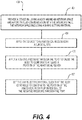
- the method 400 includes providing a device including a body having an interior space and a port in fluid communication with the interior space (step 401).
- the interior space includes a shape-setting material.
- the method 400 also includes applying the device to a tissue having an incision (step 403).
- the method 400 further includes applying a negative pressure through the port to cause the body to conform to at least a portion of the tissue (step 405).
- the method includes a step of setting the shape-setting material such that the body continues to conform to the portion of the tissue upon removal of the negative pressure through the port (step 407).
- the step 401 of providing a device including a body having an interior space and a port in fluid communication with the interior space can include, but is not limited to, providing a device 100 including a body 101 having an interior space 104 with a shape-setting material 105 included therein and a port 107 as described above with reference to Figs. 1A and 1B .
- the step 403 of applying the device to a tissue having an incision can include, but is not limited to, applying the device 100 to a tissue 150 having an incision 151 as described above with reference to Fig. 1B .
- the step 405 of applying a negative pressure through the port to cause the body to conform to at least a portion of the tissue can include, but is not limited to, applying a negative pressure through the port 107 to cause the body 101 to conform to the tissue 150 as described above with reference to Fig. 1B .
- the step 407 of setting the shape-setting material such that the body continues to conform to the portion of the tissue upon removal of the negative pressure through the port can include, but is not limited to, setting the shape-setting material 105 such that the body 101 continues to conform to the tissue 150 upon removal of the negative pressure through the port 107.
- the method 500 includes providing a device including a body comprising one or two cups, an interior space and a port in fluid communication with the interior space (step 501).
- the interior space includes a shape-setting material.
- the method 500 includes applying the device to breast tissue having at least one incision (step 503).
- the method 500 includes applying a negative pressure through the port to cause the body to conform to at least a portion of the breast tissue (step 505).
- the method 500 includes setting the shape-setting material such that the body continues to conform to the portion of the breast tissue upon removal of the negative pressure through the port (step 307).
- the step 501 of providing a device including a body comprising one or two cups, an interior space and a port in fluid communication with the interior space can include, but is not limited to, providing a device 100 including one or two separated bodies 101 formed as cup-like portions 109, an interior space 104, and a port 107 as described with reference to Figs. 1A and 1B .
- the step 503 of applying the device to breast tissue having at least one incision can include, but is not limited to, placing the device 100 over breast tissue 150 containing an incision 151. This step can be performed on a patient that has undergone a breast reconstruction or augmentation procedure that may include the placement of an implant. In some embodiments, the breast tissue may be in need of improved blood flow or re-vascularization to promote tissue healing and growth.
- the step 505 of applying a negative pressure through the port to cause the body to conform to at least a portion of the breast tissue can include, but is not limited to, connecting a vacuum to the port 107 to cause the cup-like portions 109 of the body 101 to closely conform to the shape of the breast tissue as described above with reference to Figs. 1A and 1B . When the shape-setting material hardens, the cups can retain their shape and, with the help of the adhesive layer 106, can resist decoupling from the tissue while providing support to the tissue.
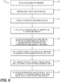
- Fig. 6 is a flow chart showing steps, not part of the invention, for treating a breast including use of a device for post-surgery application in accordance with embodiments of the present disclosure.
- the process starts by selecting a site on a breast for treatment (Step 601).
- the selection will often be based on the need to remove tissue, for example, in surgical oncology, to remove breast tissue during mastectomy, skin-sparing mastectomy, lumpectomy, or any other procedure such as revision breast augmentation, breast augmentation, or mastopexy.
- mastectomy or lumpectomy can include any variations on such procedures, such as radical mastectomy, modified radical mastectomy, or lumpectomy with sentinel node biopsy.
- the site may be selected for augmentation or aesthetic procedures, and the procedure may include simply accessing the surgical site, and/or altering the site appearance.
- the surgical procedure e.g., mastectomy, lumpectomy, surgical access
- an implant 152 is implanted within a space within the breast (Step 605).
- the surgeon may then close the surgical incision (Step 607).
- the surgeon may close the surgical incision to maintain the implant within the space within the breast.
- a device After completing the closure of the incision, a device is provided that includes a body having an interior space and a port in fluid communication with the interior space (Step 609). Further, the interior space includes a shape-setting material.
- the devices 100, 300 described above with reference to Figs. 1-3B are suitable as devices for use in this step.
- the device is applied to the breast near the surgical incision (Step 611). In some procedures, the device can surround the surgical incision.
- the surgeon can connect a source of negative pressure to the port of the device.
- the negative pressure is applied to cause the body to conform to at least a portion of the breast tissue (Step 613).
- the shape-setting material can conform to the breast tissue when a negative pressure is applied.
- the shape-setting material is set such that the body continues to conform to the portion of the breast tissue upon removal of the negative pressure through the port (Step 615).
Landscapes
- Health & Medical Sciences (AREA)
- Life Sciences & Earth Sciences (AREA)
- Veterinary Medicine (AREA)
- Public Health (AREA)
- General Health & Medical Sciences (AREA)
- Animal Behavior & Ethology (AREA)
- Heart & Thoracic Surgery (AREA)
- Vascular Medicine (AREA)
- Biomedical Technology (AREA)
- Engineering & Computer Science (AREA)
- Cardiology (AREA)
- Nursing (AREA)
- Orthopedic Medicine & Surgery (AREA)
- Oral & Maxillofacial Surgery (AREA)
- Transplantation (AREA)
- Epidemiology (AREA)
- Pain & Pain Management (AREA)
- Physical Education & Sports Medicine (AREA)
- Rehabilitation Therapy (AREA)
- Prostheses (AREA)
- Media Introduction/Drainage Providing Device (AREA)
- Surgical Instruments (AREA)
Description
- The present disclosure relates generally to devices for treating an anatomical region near a surgical site according to claim 1, and a method of setting the shape of such a device according to claim 8.
- Breast reconstruction mastectomy or breast augmentation procedures typically involve implantation of a synthetic implant such as a silicone- or saline-filled implant. In recent years, there has been a greater acceptance of skin-sparing and skin/nipple-sparing mastectomies. With such procedures, there is more skin for reconstruction and less of a need for expansion of the breast-skin envelope. Sometimes, breast skin flaps are less healthy because of diminished blood supply from underlying breast tissue removed during mastectomy. Among other things, there is not always a sufficient blood supply to clear infections or to support natural healing, and this issue can be especially challenging in the presence of synthetic implants. As a result, surgeons have found that the incidence of implant loss is reduced when implants are placed under well vascularized muscle or rapidly vascularizing acellular dermal matrix (ADM).
- Vascularization of muscle, tissue, or skin relies on strong blood flow to the region. If breast tissue after surgery is unsupported or improperly supported during healing, blood flow to the tissue can be reduced. Breast implants tend to be relatively heavy, and implants placed during surgery can weigh on tissue that is undergoing recovery. Surgical outcomes can be improved if stresses on healing tissue can be reduced.
- Similarly, healing of other surgical sites can be adversely affected if the site is insufficiently supported. In particular, healing of surgical incisions after reconstruction or augmentation of breast tissue, or other surgical sites, can be slowed by tension on the tissues and the surgical incision site. In addition, current systems to support breast tissue can place undue pressure or friction directly on the site of the incision, potentially leading to adverse outcomes such as infection or dehiscence.
-
US2004/073152 A1 discloses a device according to the preamble of claim 1 and discloses a wound dressing.US3,995,002 discloses an orthocasting system. - Accordingly, the present disclosure provides improved devices to relieve stresses on tissues near an incision, as well as the incision itself, to improve surgical outcomes. The devices provide a barrier against external contamination and help to hold the incision margins together. These advantages are reached with the features of the characterising portion of claim 1.
- Disclosed herein is a device for treating an anatomical region near a surgical, according to claim 1.
- Disclosed herein is a method of shaping the shape of the claimed device, according to claim 8.
- Reference will now be made to exemplary embodiments, examples of which are illustrated in the accompanying drawings. Wherever possible, the same reference numbers will be used throughout the drawings to refer to the same or like parts. The drawings are not necessarily to scale.
-
Fig. 1 depicts a device for providing post-surgical support of a surgical site in accordance with various embodiments of the present disclosure. -
Fig. 2A depicts a cross-sectional view of a device for providing post-surgical support of a surgical site applied to a tissue in accordance with various embodiments of the present disclosure. -
Fig. 2B depicts a perspective view of a device for providing post-surgical support of a surgical site applied to a tissue in accordance with various embodiments of the present disclosure. -
Fig. 2C depicts a cross-sectional view of a device including multiple interior spaces for providing post-surgical support of a surgical site applied to a tissue in accordance with various embodiments of the present disclosure. -
Fig. 3A depicts a perspective view of a device for providing post-surgical support of a surgical site applied to a tissue in accordance with various embodiments of the present disclosure. -
Fig. 3B depicts a cross-sectional view of a device for providing post-surgical support of a surgical site applied to a tissue in accordance with various embodiments of the present disclosure. -
Fig. 4 depicts a method of relieving stress on a tissue having an incision in accordance with various embodiments of the present disclosure. -
Fig. 5 depicts a method of treating breast tissue in accordance with various embodiments of the present disclosure. -
Fig. 6 depicts a method for treating a breast in accordance with various embodiments of the present disclosure. - Reference will now be made in detail to various embodiments of the disclosed devices and methods, examples of which are illustrated in the accompanying drawings. Wherever possible, the same reference numbers will be used throughout the drawings to refer to the same or like parts.
- In this application, the use of the singular includes the plural unless specifically stated otherwise. In this application, the use of "or" means "and/or" unless stated otherwise. Furthermore, the use of the term "including," as well as other forms such as "includes" and "included", is not limiting. Any range described herein will be understood to include the endpoints and all values between the endpoints. The term "fluid" will be understood in this application to refer to and include both liquids and gases. The term "incision" will be understood in this application to refer to and include both iatrogenic surgical incisions and wounds sustained under other conditions. In this application, "setting the shape-setting material" will be understood to mean causing the shape-setting material to set through any means, or, in the case of a self-setting material, will be understood to mean allowing the material to set or creating conditions that allow the material to set.
- The present disclosure relates to devices and methods to relieve stress or tension around surgical sites. The devices are capable of conforming to a tissue when a negative pressure is applied to the device. The devices can also include a shape-setting material. After setting of the shape-setting material, the device can continue to conform to the tissue after removal of the negative pressure. The device can provide a mechanical barrier against external contamination, help to hold incision margins together, and enhance blood flow throughout supported tissue.
-
Fig. 1 depicts adevice 100 for post-surgical application according to various embodiments of the present disclosure. Thedevice 100 can relieve stress or tension on tissues including tissues near or abutting an incision. Thedevice 100 is depicted inFigs. 2A and2B applied to asurgical site 150 having anincision 151 and, in some embodiments, animplant 152. Thedevice 100 can include abody 101 having aninner layer 102 and anouter layer 103. Aninterior space 104 can be disposed between theinner layer 102 and theouter layer 103. Theinterior space 104 can include a shape-settingmaterial 105. Aport 107 in fluid communication with theinterior space 104 can be disposed on thebody 101. By setting the shape-settingmaterial 105 in theinterior space 104, thedevice 100 can be fixed in a conformation to provide mechanical support to thesurgical site 150 without the need for continued application of negative pressure through theport 107. - The
body 101 of thedevice 100 can be flexible to conform to at least a portion of the tissue for which the stress is to be relieved. Thebody 101 can be made of a variety of suitable materials. In some embodiments, thebody 101 can be formed of a single sheet of material that is folded to create theinner layer 102 and theouter layer 103. In other embodiments, thebody 101 can be formed of an initially separatedinner layer 102 andouter layer 103 of material that are joined at aseam 101a to form thebody 101. Theseam 101a can be formed by use of adhesives or glues, heat-sealing, crimping together of the layers, or any other suitable method. In an exemplary embodiment, thebody 101 of thedevice 100 can be waterproof or water-resistant to keep theincision 151 protected from moisture while, for example, the wearer showers. In some embodiments, thedevice 100 can include one or two separated cup-like portions 109 that may be linked by connecting elements as in, for example, a brassiere. The cup-like portions 109 can be sized and shaped to cover some or all of the breast tissue to provide support to the breast tissue. - As shown in
Fig. 2A , theinner layer 102 can contact thetissue 150 of a wearer. In various embodiments, theinner layer 102 and theouter layer 103 can be formed of the same or different materials. The material composition of theinner layer 102 orouter layer 103 can include polymers, film dressings, silicone, or any other material that is compatible with skin contact. In some embodiments, the materials of theinner layer 102 orouter layer 103 can be breathable, waterproof, transparent, or sterilizable. In some embodiments, theinner layer 102 and theouter layer 103 can use materials similar to those in the V.A.C. ® Therapy units (KCI Licensing, San Antonio, TX). In an exemplary embodiment, theouter layer 103 can be formed of a material that is puncture-resistant or leak-proof to prevent air from entering thebody 101 orinterior volume 104 during application of negative pressure. - To secure the
device 100 to thetissue 150 during initial placement and during subsequent use, an inner surface of theinner layer 102 can include anadhesive layer 106 made of a tacky, sticky, or adherent material. In some embodiments, the adhesive layer does not contact theincision 151. The adhesive layer can include, but is not limited to, tapes, fibrin sealants, cyanoacrylates and other acrylate polymers, hydroabietic acid, gelatin and thrombin products, polyethylene glycol polymers, albumin and glutaraldehyde products, and any other suitable adhesive element. In some embodiments, theadhesive layer 106 can attach to the user at least on or below the breast and on or above the breast to provide support for the breast. Theadhesive layer 106 can be formed as an unbroken surface on the inner surface of theinner layer 102 or can be formed in segments. In some embodiments, theinterior volume 104 can include holes or passages through to the inner surface of theinner layer 102 so that the surface of thetissue 150 and the interior volume are in fluid communication. In such an embodiment, theadhesive layer 106 can provide an airtight barrier to allow vacuum to be applied near thetissue 150 through theinterior volume 104. Application of vacuum through theinterior volume 104 to the vicinity of thetissue 150 can facilitate removal of accumulating fluids from theincision 151. - Additional or alternative methods of holding the
device 100 to atissue 150 are contemplated. In some embodiments, thedevice 100 can additionally or alternatively be held in place on thetissue 150 using a drape 110 (Fig. 2B ). Thedrape 110 can cover at least a portion of thedevice 100 and prevent thedevice 100 from separating from thetissue 150. In some embodiments, thedrape 110 can be waterproof or water-resistant to protect thedevice 100 andunderlying tissue 150 from coming into contact with water. In some embodiments, thedrape 110 can be an elastic bandage such as an ACE™ elastic bandage (3M Corporation, St. Paul, MN) or can include conventional brassiere mechanisms such as straps. In some embodiments, thedrape 110 can include TEGADERM™ (3M Corporation, St. Paul, MN) or other adhesive films for wound dressings. In such embodiments, thedrape 110 may be attached both to theouter layer 103 or any other suitable element of thedevice 100 and to tissue surrounding thetissue 150 having anincision 151. In some embodiments, thedrape 110 can provide an airtight barrier to allow vacuum to be applied near thetissue 150 and within theinterior volume 104. In such an embodiment, theinner layer 102 can be partially complete (i.e., theinner layer 102 can have holes). - In some embodiments, the
device 100 can include awicking layer 108 to draw fluid away from theincision 151 and, optionally, towards theport 107 for removal. Thewicking layer 108 can include antimicrobial agents. Any suitable antimicrobial agent can be used by application or implantation into thewicking layer 108 or other surface of thedevice 100 of the present disclosure. In certain embodiments, the antimicrobial agent includes at least one of benzethonium chloride, chlorhexidine, benzalkonium chloride, and silver nitrate. In other embodiments, the antimicrobial agent includes poly-hexa-methylene biguanide hydrochloride, silver ions, or chitosan. In some embodiments, suitable antimicrobial compounds also include cationic peptides such as nisin, cathelicidin, and abaecin. Additional suitable anti-microbial compounds include quaternary ammonium compounds such as methylbenzethonium chloride, cetalkonium chloride, dofanium chloride, tetraethylammonium bromide, didecyldimethylammonium chloride, and domiphen bromide. In some embodiments, combinations of different anti-microbial agents can be used. Examples of antimicrobial combinations include silver and chlorhexidine as well as chlorhexidine with various quaternary ammonium compounds. - Antibiotics or other therapeutic compounds may be applied to surfaces that contact the tissue such as the
wicking layer 108, theadhesive layer 106, or theinner layer 102. Exemplary therapeutic compounds can include antibiotics such as penicillin, gentamycin, or streptomycin; anti-inflammatory compounds such as non-steroidal anti-inflammatory drugs; numbing agents; or other formulations as needed for a specific application. - In some embodiments, the
device 100 can include a first interior space 104a and a secondinterior space 104b that is separate from the first interior space 104a as shown inFig. 2C . The first interior space 104a and the secondinterior space 104b can be isolated from one another or can be in fluid communication through a small channel. In some embodiments, the shape-settingmaterial 105 can be placed in the first interior space 104a and theport 107 can be in fluid communication with the secondinterior space 104b. In this way, the incision site can be in fluid communication with oneinterior space 104b and a vacuum pump, and the shape-settingmaterial 105 can be isolated in a different interior space 104a. The first interior space 104a and the secondinterior space 104b can have different ports that can be individually opened and closed. Separation of the first interior space 104a from the secondinterior space 104b can enable the use of non-porous materials as the shape-settingmaterial 105. The first and secondinterior spaces 104a, 104b can be arranged to correspond to different locations on or around thetissue 150. In some embodiments, the first and secondinterior spaces 104a, 104b can correspond to different quadrants of thetissue 150, the upper pole and lower pole of the breast, the incision site and a spared site, the breast and a torso, or any other suitable positioning scheme. In some embodiments, the first interior space 104a and the secondinterior space 104b are arranged in layers of thedevice 100. - The shape-setting
material 105 can initially be in an expanded state and can transform to a compressed state upon application of negative pressure. In some embodiments, the shape-settingmaterial 105 can include a foam or a sponge-like material. As a non-limiting example, the shape-settingmaterial 105 can include a foam such as GranuFoam™ as found in Prevena™ dressings (KCI, San Antonio, TX). Collapse or compression of the shape-settingmaterial 105 under vacuum can allow the shape-settingmaterial 105 to closely conform to thetissue 150 to which thedevice 100 is applied. - Mechanical support can relieve stress on the
tissue 150 particularly in surgical indications where a relativelyheavy implant 152 has been used. In some embodiments, the shape-settingmaterial 105 can be a self-setting polymer or foam, cement, rubber cement, cyanoacrylate, dental putty or caulk, or two-part epoxy. In shape-settingmaterial 105 can be a UV-curing liquid silicone rubber or a thermoset polymer such as polymethyl methacrylate (PMMA). In some embodiments, the shape-settingmaterial 105 can be a pre-formed polyurethane foam including, for example, PMMA or a biocompatible cement. The foam can undergo compression and can conform to an anatomical feature when placed under vacuum at which point the PMMA or cement can be cured to lock in the shape. The shape-settingmaterial 105 can harden in a manner similar to, for example, a cast to provide mechanical support to thetissue 150. In various embodiments, application of thedevice 100 to the tissue or setting of the shape-settingmaterial 105 can occur while the user is positioned upright or supine. - In accordance with various embodiments, the shape-setting
material 105 can be self-setting or can be activated through an external stimulus such as, but not limited to, ultraviolet light, heat, or the activation of a reactive component to the shape-settingmaterial 105. In some embodiments, theport 107 can be used to introduce the reactive component (e.g., a hardener, an activating solution, or one of the two parts of a two-part epoxy) into theinterior space 104 before the application of negative pressure. In some embodiments, the process of setting the shape-settingmaterial 105 is insufficiently exothermic to cause discomfort to a wearer or to damage thetissue 150. In some embodiments, thedevice 100 can include a heat-shielding or heat-reflecting material that thermally insulates thetissue 150 from the shape-settingmaterial 105. In some embodiments, the shape-settingmaterial 105 can have a filamentous, granular, or porous structure to improve the evacuation of air from theinterior space 104 when a negative pressure is applied at theport 107. - The
port 107 can allow the introduction or extraction of fluids from theinterior space 104 of thedevice 100. Theport 107 can include various fittings to facilitate connection of gas or liquid sources or vacuum sources. The fittings can include Luer fittings or locks, inflation valves or stems, threads, or any other suitable connection or coupling mechanism. In some embodiments, theport 107 can include a one-way valve that only allows extraction of fluids. In some embodiments, one ormore ports 107 can extend through the inner layer and can be used to remove accumulated fluid from theincision 151. In other embodiments, theinner layer 102 can have a hole or holes to allow fluids to pass into theinterior volume 104 where they are eventually evacuated through one ormore ports 107. In certain embodiments, theport 107 can be sealed temporarily or permanently to prevent further transfer of fluids into or out of theinterior volume 104. In one embodiment, theinterior volume 104, the first interior volume 104a, or the secondinterior volume 104b can be further subdivided to provide multiple chambers that, for example, can be evacuated independently throughindependent ports 107 or can contain separate portions of shape-settingmaterial 105 that can be set at different times. In some embodiments, applying a vacuum source to theport 107 can cause theadhesive layer 106 to firmly contact the tissue thereby improving the adhesion. - The
device 100 can be designed to fit the body shape or tissue shape of the user. In some embodiments, thedevice 100 or portions of the device can be sized according to standard women's brassiere sizing conventions. Thedevice 100 can be worn for various lengths of time as required by a user or by a treatment regimen. For example, thedevice 100 can be worn between dressing changes during recovery from surgery at which time an old device may be replaced with a new device. Periodic replacement of thedevice 100 can continue until the incision or tissue has healed or until another recovery milestone is reached such as removal of surgical drains from a user. In some embodiments, thedevice 100 can be worn for one day, several days, one week, or any time period in between as needed for a specific application. -
Figs. 3A and3B depict adevice 300 for post-surgical application in accordance with the present disclosure.Fig. 3A depicts a perspective view, whileFig. 3B depicts a cross-sectional view of thedevice 300 applied totissue 150 near anincision 151. Thedevice 300 can relieve stress or tension on tissues including tissues near or abutting an incision. Thedevice 300 can include abody 301 having aninner layer 302 and anouter layer 303. Aninterior space 304 can be disposed between theinner layer 302 and theouter layer 303. Theinterior space 304 can include a shape-settingmaterial 305. Aport 307 in fluid communication with theinterior space 304 can be disposed on thebody 301. By setting the shape-settingmaterial 305 in theinterior space 304, thedevice 300 can be fixed in a conformation to provide mechanical support to thetissue 150 without the need for continued application of negative pressure through theport 307. - The
body 301 of thedevice 300 can be flexible to conform to at least a portion of the tissue for which the stress is to be relieved. Thebody 301 can be made of a variety of suitable materials. In some embodiments, thebody 301 can be formed of a single sheet of material that is folded to create theinner layer 302 and theouter layer 303. In other embodiments, thebody 301 can be formed of an initially separatedinner layer 302 andouter layer 303 of material. Theinner layer 302 andouter layer 303 can be joined at a seam or can press together upon application of negative pressure. In an exemplary embodiment, thebody 301 of thedevice 300 can be waterproof or water-resistant to keep an incision protected from moisture while, for example, the wearer showers. In some embodiments, thebody 301 can be formed to have a shape that conforms to tissue to be treated. For example, thebody 301 can have a shape similar to a belly sling or girdle to treat certain abdominal wounds. - As shown in
Fig. 3B , theinner layer 302 can contact tissue of a wearer. In various embodiments, theinner layer 302 and theouter layer 303 can be formed of the same or different materials. The material composition of theinner layer 302 orouter layer 303 can include polymers or any other suitable material. In some embodiments, the materials of theinner layer 302 orouter layer 303 can be sterilizable. In an exemplary embodiment, theouter layer 303 can be formed of a material that is puncture-resistant or leak-proof to prevent air from entering thebody 301 orinterior volume 304 during application of negative pressure. - To better adhere the
device 300 to the tissue during initial placement and during subsequent wear, theinner layer 302 can include anadhesive layer 306 made of a tacky, sticky, or adherent material. In some embodiments, the adhesive layer does not contact the incision. The adhesive layer can include, but is not limited to, tapes, fibrin sealants, cyanoacrylates and other acrylate polymers, hydroabietic acid, gelatin and thrombin products, polyethylene glycol polymers, albumin and glutaraldehyde products, and any other suitable adhesive element. Theadhesive layer 306 can be formed as an unbroken surface on theinner layer 302 or can be formed in segments. In some embodiments, theadhesive layer 306 can provide an airtight barrier to allow vacuum to be applied near the tissue and within theinterior volume 304. In such an embodiment, theinner layer 302 can be partially complete (i.e., theinner layer 302 can have holes). - Additional or alternative methods of holding the
device 300 fast to atissue 150 are contemplated. In some embodiments, thedevice 300 can additionally or alternatively be held in place on the tissue using adrape 310. Thedrape 310 can cover at least a portion of thedevice 300 and prevent thedevice 300 from separating from the tissue. In some embodiments, thedrape 310 can be waterproof or water-resistant to protect thedevice 300 and underlying tissue from coming into contact with water. In some embodiments, thedrape 310 can be an elastic bandage such as an ACE™ elastic bandage (3M Corporation, St. Paul, MN). In some embodiments, thedrape 310 can include TEGADERM™ (3M Corporation, St. Paul, MN) or other adhesive films for wound dressings. In such embodiments, thedrape 310 may be attached both to theouter layer 303 or any other suitable element of thedevice 300 and to tissue surrounding the tissue having an incision. In some embodiments, thedrape 310 can provide an airtight barrier to allow vacuum to be applied near the tissue and within theinterior volume 304. In such an embodiment, theinner layer 302 can be partially complete (i.e., theinner layer 302 can have holes). - In some embodiments, the
device 300 can include awicking layer 308 to draw accumulating fluid away from the incision and to theport 307 for removal. Thewicking layer 308 can include antimicrobial agents. Any suitable antimicrobial agent can be used by application or implantation into thewicking layer 308 or other surface of thedevice 300 of the present disclosure. In certain embodiments, the antimicrobial agent includes at least one of benzethonium chloride, chlorhexidine, benzalkonium chloride, and silver nitrate. In other embodiments, the antimicrobial agent includes poly-hexa-methylene biguanide hydrochloride, silver ions, or chitosan. In some embodiments, suitable antimicrobial compounds also include cationic peptides such as nisin, cathelicidin, and abaecin. Additional suitable anti-microbial compounds include quaternary ammonium compounds such as methylbenzethonium chloride, cetalkonium chloride, dofanium chloride, tetraethylammonium bromide, didecyldimethylammonium chloride, and domiphen bromide. In some embodiments, combinations of different anti-microbial agents can be used. Examples of antimicrobial combinations include silver and chlorhexidine as well as chlorhexidine with various quaternary ammonium compounds. - Antibiotics or other therapeutic compounds may be applied to surfaces that contact the tissue such as the
wicking layer 308, theadhesive layer 306, or theinner layer 302. Exemplary therapeutic compounds can include antibiotics such as penicillin, gentamycin, or streptomycin; anti-inflammatory compounds such as non-steroidal anti-inflammatory drugs; numbing agents; or other formulations as needed for a specific application. - The shape-setting
material 305 can initially be in an expanded state and can transform to a compressed state upon application of negative pressure. In some embodiments, the shape-settingmaterial 305 can include a foam or a sponge-like material. As a non-limiting example, the shape-settingmaterial 305 can include a foam such as GranuFoam™ as found in Prevena™ dressings (KCI, San Antonio, TX). Collapse or compression of the shape-settingmaterial 305 under vacuum can allow the shape-settingmaterial 305 to closely conform to tissue to which thedevice 300 is applied. - In some embodiments, the shape-setting
material 305 can be a self-setting polymer or foam. The shape-settingmaterial 305 can advantageously harden in a manner similar to, for example, a cast to provide mechanical support to the tissue. In various embodiments, application of thedevice 300 to the tissue or setting of the shape-settingmaterial 305 can occur while the user is positioned upright or supine. - In accordance with various embodiments, the shape-setting
material 305 can be self-setting or can be activated through an external stimulus such as, but not limited to, ultraviolet light, heat, or the activation of a reactive component to the shape-settingmaterial 305. In some embodiments, theport 307 can be used to introduce the reactive component (e.g., a hardener, an activating solution, or one of the two parts of a two-part epoxy) into theinterior space 304 before the application of negative pressure. In some embodiments, the process of setting the shape-settingmaterial 305 is insufficiently exothermic to cause discomfort to a wearer or to damage the tissue. In some embodiments, thedevice 300 can include a heat-shielding or heat-reflecting material that thermally isolates the tissue from the shape-settingmaterial 305. In some embodiments, the shape-settingmaterial 305 can have a filamentous, granular, or porous structure to improve the evacuation of air from theinterior space 304 when a negative pressure is applied at theport 307. - The
port 307 can allow the introduction or extraction of fluids from theinterior space 304 of thedevice 300. Theport 307 can include various fittings to facilitate connection of gas or liquid sources or vacuum sources. The fittings can include Luer fittings or locks, inflation valves or stems, threads, or any other suitable connection or coupling mechanism. In some embodiments, theport 307 can include a one-way valve that only allows extraction of fluids. In some embodiments, one ormore ports 307 can extend through the inner layer and can be used to remove fluid from an incision. In other embodiments, theinner layer 302 can have a hole or holes to allow fluids to pass into theinterior volume 304 where they are eventually evacuated through one ormore ports 307. In certain embodiments, theport 307 can be sealed temporarily or permanently to prevent further transfer of fluids into or out of theinterior volume 304. In any embodiment, theinterior volume 304 can be further subdivided to provide multiple chambers that, for example, can be evacuated independently throughindependent ports 307 or can contain separate portions of shape-settingmaterial 305 that can be set at different times. In some embodiments, applying a vacuum source to theport 307 can cause theadhesive layer 306 to firmly contact the tissue thereby improving the adhesion. - The
device 300 can be designed to fit the body shape or tissue shape of the user. Thedevice 300 can be worn for various lengths of time as required by a user or by a treatment regimen. For example, thedevice 300 can be worn between dressing changes during recovery from surgery at which time theold device 300 may be replaced with anew device 300. Periodic replacement of thedevice 300 can continue until the incision or tissue has healed or until another recovery milestone is reached such as removal of surgical drains from a user. In some embodiments, thedevice 300 can be worn for one day, several days, one week, or any time period in between as needed for a specific application. - As shown in
Fig. 4 , amethod 400 of setting the shape of the device is provided in accordance with various embodiments of the present disclosure. Although the method is described with respect to specific devices and figures, it will be understood that the methods can be implemented using any of the various embodiments discussed herein unless otherwise inconsistent with the description. Themethod 400 includes providing a device including a body having an interior space and a port in fluid communication with the interior space (step 401). The interior space includes a shape-setting material. Themethod 400 also includes applying the device to a tissue having an incision (step 403). Themethod 400 further includes applying a negative pressure through the port to cause the body to conform to at least a portion of the tissue (step 405). The method includes a step of setting the shape-setting material such that the body continues to conform to the portion of the tissue upon removal of the negative pressure through the port (step 407). - The
method 400 will now be described in greater detail with reference to the embodiments depicted in previous figures. Thestep 401 of providing a device including a body having an interior space and a port in fluid communication with the interior space can include, but is not limited to, providing adevice 100 including abody 101 having aninterior space 104 with a shape-settingmaterial 105 included therein and aport 107 as described above with reference toFigs. 1A and 1B . Thestep 403 of applying the device to a tissue having an incision can include, but is not limited to, applying thedevice 100 to atissue 150 having anincision 151 as described above with reference toFig. 1B . - The
step 405 of applying a negative pressure through the port to cause the body to conform to at least a portion of the tissue can include, but is not limited to, applying a negative pressure through theport 107 to cause thebody 101 to conform to thetissue 150 as described above with reference toFig. 1B . Thestep 407 of setting the shape-setting material such that the body continues to conform to the portion of the tissue upon removal of the negative pressure through the port can include, but is not limited to, setting the shape-settingmaterial 105 such that thebody 101 continues to conform to thetissue 150 upon removal of the negative pressure through theport 107. - As shown in
Fig. 5 , amethod 500, not part of the invention, of treating breast tissue is provided in accordance with various embodiments of the present disclosure. Themethod 500 includes providing a device including a body comprising one or two cups, an interior space and a port in fluid communication with the interior space (step 501). The interior space includes a shape-setting material. Themethod 500 includes applying the device to breast tissue having at least one incision (step 503). Themethod 500 includes applying a negative pressure through the port to cause the body to conform to at least a portion of the breast tissue (step 505). Themethod 500 includes setting the shape-setting material such that the body continues to conform to the portion of the breast tissue upon removal of the negative pressure through the port (step 307). - The
method 500 will now be described in greater detail with reference to the embodiments depicted in previous figures. Thestep 501 of providing a device including a body comprising one or two cups, an interior space and a port in fluid communication with the interior space can include, but is not limited to, providing adevice 100 including one or two separatedbodies 101 formed as cup-like portions 109, aninterior space 104, and aport 107 as described with reference toFigs. 1A and 1B . - The
step 503 of applying the device to breast tissue having at least one incision can include, but is not limited to, placing thedevice 100 overbreast tissue 150 containing anincision 151. This step can be performed on a patient that has undergone a breast reconstruction or augmentation procedure that may include the placement of an implant. In some embodiments, the breast tissue may be in need of improved blood flow or re-vascularization to promote tissue healing and growth. Thestep 505 of applying a negative pressure through the port to cause the body to conform to at least a portion of the breast tissue can include, but is not limited to, connecting a vacuum to theport 107 to cause the cup-like portions 109 of thebody 101 to closely conform to the shape of the breast tissue as described above with reference toFigs. 1A and 1B . When the shape-setting material hardens, the cups can retain their shape and, with the help of theadhesive layer 106, can resist decoupling from the tissue while providing support to the tissue. -
Fig. 6 is a flow chart showing steps, not part of the invention, for treating a breast including use of a device for post-surgery application in accordance with embodiments of the present disclosure. As shown, the process starts by selecting a site on a breast for treatment (Step 601). The selection will often be based on the need to remove tissue, for example, in surgical oncology, to remove breast tissue during mastectomy, skin-sparing mastectomy, lumpectomy, or any other procedure such as revision breast augmentation, breast augmentation, or mastopexy. It should be noted that as used herein, mastectomy or lumpectomy can include any variations on such procedures, such as radical mastectomy, modified radical mastectomy, or lumpectomy with sentinel node biopsy. In some cases, the site may be selected for augmentation or aesthetic procedures, and the procedure may include simply accessing the surgical site, and/or altering the site appearance. - After the site is selected, the surgical procedure (e.g., mastectomy, lumpectomy, surgical access) is performed on the breast (Step 603). In accordance with certain procedures, an
implant 152 is implanted within a space within the breast (Step 605). The surgeon may then close the surgical incision (Step 607). For procedures that utilize animplant 152, the surgeon may close the surgical incision to maintain the implant within the space within the breast. - After completing the closure of the incision, a device is provided that includes a body having an interior space and a port in fluid communication with the interior space (Step 609). Further, the interior space includes a shape-setting material. The
devices Figs. 1-3B are suitable as devices for use in this step. The device is applied to the breast near the surgical incision (Step 611). In some procedures, the device can surround the surgical incision. A - The surgeon can connect a source of negative pressure to the port of the device. The negative pressure is applied to cause the body to conform to at least a portion of the breast tissue (Step 613). As described previously, the shape-setting material can conform to the breast tissue when a negative pressure is applied. Finally, the shape-setting material is set such that the body continues to conform to the portion of the breast tissue upon removal of the negative pressure through the port (Step 615).
Claims (15)
- A device (100, 300) for treating an anatomical region near a surgical site (150) comprising:a body (101, 103) including an interior space (104, 304), the body further includinga shape-setting material (105, 305) disposed within the interior space (104, 304); anda port (107, 307) disposed on the body (101, 301) and in fluid communication with the interior space (104, 304),wherein application of negative pressure through the port (107, 307) causes the body (101, 301) to conform to at least a portion of an anatomical region near a surgical site (150, 250), andcharacterised in that setting of the shape-setting material (105, 305) causes the body (101, 301) to continue to conform to the portion of the anatomical region upon removal of the negative pressure through the port (107, 307).
- The device (100, 300) of claim 1, wherein the body (101, 301) comprises a polymer.
- The device (100, 300) of any of claims 1-2, wherein an inner surface of the body (101, 301) includes an adhesive layer (106, 306) to adhere the device (100, 300) to the anatomical region.
- The device (100, 300) of any of claims 1-3, wherein the shape-setting material (105, 305) comprises a self-setting polymer.
- The device (100, 300) of any of claims 1-4, wherein the port (107, 307) is sealable to prevent fluid exchange.
- The device (100, 300) of any of claims 1-5, wherein the port (107, 307) comprises a oneway valve.
- The device (100, 300) of any of claims 1-6, further comprising an elastic bandage to maintain a position of the device (100, 300) relative to the anatomical region.
- A method of setting the shape of a device according to claim 1, comprising:providing the device (100, 300) including a body (101, 301) having an interior space (104, 304) and a port (107, 307) in fluid communication with the interior space (104, 304), the interior space (104, 304) including a shape-setting material (105, 305);applying the device to an anatomical region near a surgical site (150);applying a negative pressure through the port (107, 307) to cause the body (101, 301) to conform to at least a portion of the anatomical region; andsetting the shape-setting material (105, 305) such that the body continues to conform to the portion of the anatomical region upon removal of the negative pressure through the port (107, 307).
- The method of claim8, wherein the body (107, 307) comprises a polymer.
- The method of any of claims 8-9, wherein an inner
surface of the body (101, 301) includes an adhesive layer (106, 306) to adhere the device (100, 300) to the tissue. - The method of any of claims 8-10, wherein the shapesetting material (105, 305) comprises a self-setting polymer.
- The method of any of claims 8-11, wherein the port (107, 307) is sealable to prevent fluid exchange.
- The method of any of claims 8-12, wherein the port (107, 307) comprises a one-way valve.
- The method of any of claims 8-13, wherein the anatomical region includes breast tissue.
- The method of any of claims 8-14, further comprising removing accumulated fluids through the port (107, 307).
Priority Applications (1)
| Application Number | Priority Date | Filing Date | Title |
|---|---|---|---|
| EP20177694.5A EP3777779A3 (en) | 2016-04-19 | 2017-04-18 | Stress relieving device |
Applications Claiming Priority (2)
| Application Number | Priority Date | Filing Date | Title |
|---|---|---|---|
| US201662324571P | 2016-04-19 | 2016-04-19 | |
| PCT/US2017/028058 WO2017184559A1 (en) | 2016-04-19 | 2017-04-18 | Stress relieving device |
Related Child Applications (1)
| Application Number | Title | Priority Date | Filing Date |
|---|---|---|---|
| EP20177694.5A Division EP3777779A3 (en) | 2016-04-19 | 2017-04-18 | Stress relieving device |
Publications (2)
| Publication Number | Publication Date |
|---|---|
| EP3445293A1 EP3445293A1 (en) | 2019-02-27 |
| EP3445293B1 true EP3445293B1 (en) | 2020-06-03 |
Family
ID=58672680
Family Applications (2)
| Application Number | Title | Priority Date | Filing Date |
|---|---|---|---|
| EP17722208.0A Not-in-force EP3445293B1 (en) | 2016-04-19 | 2017-04-18 | Stress relieving device |
| EP20177694.5A Withdrawn EP3777779A3 (en) | 2016-04-19 | 2017-04-18 | Stress relieving device |
Family Applications After (1)
| Application Number | Title | Priority Date | Filing Date |
|---|---|---|---|
| EP20177694.5A Withdrawn EP3777779A3 (en) | 2016-04-19 | 2017-04-18 | Stress relieving device |
Country Status (6)
| Country | Link |
|---|---|
| US (2) | US20170296422A1 (en) |
| EP (2) | EP3445293B1 (en) |
| AU (1) | AU2017254468A1 (en) |
| CA (1) | CA3021581A1 (en) |
| ES (1) | ES2807198T3 (en) |
| WO (1) | WO2017184559A1 (en) |
Families Citing this family (8)
| Publication number | Priority date | Publication date | Assignee | Title |
|---|---|---|---|---|
| JP6437517B2 (en) | 2013-03-15 | 2018-12-12 | インセラ セラピューティクス,インク. | Vascular treatment apparatus and method |
| CN108697423A (en) | 2016-02-16 | 2018-10-23 | 伊瑟拉医疗公司 | The part flow arrangement of suction unit and anchoring |
| USD847864S1 (en) | 2018-01-22 | 2019-05-07 | Insera Therapeutics, Inc. | Pump |
| US11504260B2 (en) | 2018-10-04 | 2022-11-22 | Lipocosm, Llc | Rigidifying brace |
| US12121077B2 (en) | 2018-10-04 | 2024-10-22 | Lipocosm, Llc | Brassiere with rigidifying cups |
| US11540894B2 (en) | 2018-10-04 | 2023-01-03 | Lipocosm, Llc | Rigiditying brace |
| US12042458B2 (en) | 2020-12-07 | 2024-07-23 | Lipocosm, Llc | External vacuum tissue expander with slidable rim |
| US11547155B2 (en) | 2020-12-07 | 2023-01-10 | Lipocosm, Llc | External vacuum expander with non-adhesive rim |
Family Cites Families (8)
| Publication number | Priority date | Publication date | Assignee | Title |
|---|---|---|---|---|
| US3995002A (en) * | 1974-11-07 | 1976-11-30 | Brown Dennis N | Orthocasting system |
| FR2653098B1 (en) * | 1989-10-16 | 1992-04-24 | Lepinoy Ind | DEVICE OF THE TYPE COMPRISING A RIGID WRAPPING SHELL, DEFINING AN INTERNAL VOLUME AND AT LEAST ONE SEALED CHAMBER OCCUPYING THE SAME. |
| US7094212B2 (en) * | 2002-10-11 | 2006-08-22 | Ossur Hf | Rigid dressing |
| US7037283B2 (en) * | 2002-10-18 | 2006-05-02 | Ossur Hf | Casting product and method for forming the same |
| US8062272B2 (en) * | 2004-05-21 | 2011-11-22 | Bluesky Medical Group Incorporated | Flexible reduced pressure treatment appliance |
| JP5263882B2 (en) * | 2006-02-07 | 2013-08-14 | コビディエン・リミテッド・パートナーシップ | Surgical wound dressing |
| US20090143868A1 (en) * | 2007-11-27 | 2009-06-04 | Center For International Rehabilitation | Vacuum based impression and alignment device and method |
| JP5406283B2 (en) * | 2008-05-30 | 2014-02-05 | ケーシーアイ ライセンシング インコーポレイテッド | Decompression / compression system and device for curved body parts |
-
2017
- 2017-04-18 ES ES17722208T patent/ES2807198T3/en active Active
- 2017-04-18 EP EP17722208.0A patent/EP3445293B1/en not_active Not-in-force
- 2017-04-18 AU AU2017254468A patent/AU2017254468A1/en not_active Abandoned
- 2017-04-18 WO PCT/US2017/028058 patent/WO2017184559A1/en not_active Ceased
- 2017-04-18 CA CA3021581A patent/CA3021581A1/en not_active Abandoned
- 2017-04-18 US US15/490,054 patent/US20170296422A1/en not_active Abandoned
- 2017-04-18 EP EP20177694.5A patent/EP3777779A3/en not_active Withdrawn
-
2020
- 2020-11-23 US US17/101,164 patent/US20210069055A1/en not_active Abandoned
Non-Patent Citations (1)
| Title |
|---|
| None * |
Also Published As
| Publication number | Publication date |
|---|---|
| EP3445293A1 (en) | 2019-02-27 |
| EP3777779A2 (en) | 2021-02-17 |
| WO2017184559A1 (en) | 2017-10-26 |
| AU2017254468A1 (en) | 2018-11-08 |
| ES2807198T3 (en) | 2021-02-22 |
| US20210069055A1 (en) | 2021-03-11 |
| EP3777779A3 (en) | 2021-03-03 |
| CA3021581A1 (en) | 2017-10-26 |
| US20170296422A1 (en) | 2017-10-19 |
| WO2017184559A8 (en) | 2017-12-14 |
Similar Documents
| Publication | Publication Date | Title |
|---|---|---|
| US20210069055A1 (en) | Stress relieving device | |
| RU2465019C2 (en) | Systems and methods for unload and low pressure therapy | |
| JP5822955B2 (en) | Method and apparatus for tissue expansion | |
| US7338482B2 (en) | External catheter access to vacuum bandage | |
| US20030212359A1 (en) | Conformable bi-laminate compression bolster and method for using same | |
| MX2010012958A (en) | Reduced-pressure surgical wound treatment systems and methods. | |
| CN103124571A (en) | Method and device for applying negative pressure wound therapy for closed incisions | |
| CN102625677A (en) | Methods and products for reducing tissue trauma using absorbent stress-distributing materials | |
| US12390221B2 (en) | Closure apparatuses and methods for ulcers and irregular skin defects | |
| BR112014015912B1 (en) | post-surgical dressing for breast | |
| US20210106737A1 (en) | Open wound negative pressure wound therapy protection system | |
| WO2020073021A1 (en) | Rigidifying brace | |
| JP2013514096A (en) | Cutting aid for wound dressing for decompression treatment | |
| US20200289334A1 (en) | Medical bandage with support and method of using the same | |
| US20170043067A1 (en) | Wound care device | |
| US8523859B2 (en) | Vacuum-assisted wound healing around a pin-site | |
| WO2017034451A1 (en) | Surgical bandage with stabilizing elements | |
| US20260115053A1 (en) | Wound dressing | |
| US20260115050A1 (en) | Wound dressing | |
| Ahmad et al. | Evaluation of Outcome of the Vaccum Assisted Closure in Patients with Infected Wound of Musculoskeletal System | |
| UA124961U (en) | A METHOD OF VACUUM THERAPY FOR THE TREATMENT OF CROSS-WOUND INJURY |
Legal Events
| Date | Code | Title | Description |
|---|---|---|---|
| STAA | Information on the status of an ep patent application or granted ep patent |
Free format text: STATUS: UNKNOWN |
|
| STAA | Information on the status of an ep patent application or granted ep patent |
Free format text: STATUS: THE INTERNATIONAL PUBLICATION HAS BEEN MADE |
|
| PUAI | Public reference made under article 153(3) epc to a published international application that has entered the european phase |
Free format text: ORIGINAL CODE: 0009012 |
|
| STAA | Information on the status of an ep patent application or granted ep patent |
Free format text: STATUS: REQUEST FOR EXAMINATION WAS MADE |
|
| 17P | Request for examination filed |
Effective date: 20181012 |
|
| AK | Designated contracting states |
Kind code of ref document: A1 Designated state(s): AL AT BE BG CH CY CZ DE DK EE ES FI FR GB GR HR HU IE IS IT LI LT LU LV MC MK MT NL NO PL PT RO RS SE SI SK SM TR |
|
| AX | Request for extension of the european patent |
Extension state: BA ME |
|
| DAV | Request for validation of the european patent (deleted) | ||
| DAX | Request for extension of the european patent (deleted) | ||
| GRAP | Despatch of communication of intention to grant a patent |
Free format text: ORIGINAL CODE: EPIDOSNIGR1 |
|
| STAA | Information on the status of an ep patent application or granted ep patent |
Free format text: STATUS: GRANT OF PATENT IS INTENDED |
|
| INTG | Intention to grant announced |
Effective date: 20200107 |
|
| GRAS | Grant fee paid |
Free format text: ORIGINAL CODE: EPIDOSNIGR3 |
|
| GRAA | (expected) grant |
Free format text: ORIGINAL CODE: 0009210 |
|
| STAA | Information on the status of an ep patent application or granted ep patent |
Free format text: STATUS: THE PATENT HAS BEEN GRANTED |
|
| AK | Designated contracting states |
Kind code of ref document: B1 Designated state(s): AL AT BE BG CH CY CZ DE DK EE ES FI FR GB GR HR HU IE IS IT LI LT LU LV MC MK MT NL NO PL PT RO RS SE SI SK SM TR |
|
| REG | Reference to a national code |
Ref country code: GB Ref legal event code: FG4D |
|
| REG | Reference to a national code |
Ref country code: CH Ref legal event code: EP Ref country code: AT Ref legal event code: REF Ref document number: 1276220 Country of ref document: AT Kind code of ref document: T Effective date: 20200615 |
|
| REG | Reference to a national code |
Ref country code: DE Ref legal event code: R096 Ref document number: 602017017672 Country of ref document: DE |
|
| REG | Reference to a national code |
Ref country code: LT Ref legal event code: MG4D |
|
| PG25 | Lapsed in a contracting state [announced via postgrant information from national office to epo] |
Ref country code: GR Free format text: LAPSE BECAUSE OF FAILURE TO SUBMIT A TRANSLATION OF THE DESCRIPTION OR TO PAY THE FEE WITHIN THE PRESCRIBED TIME-LIMIT Effective date: 20200904 Ref country code: NO Free format text: LAPSE BECAUSE OF FAILURE TO SUBMIT A TRANSLATION OF THE DESCRIPTION OR TO PAY THE FEE WITHIN THE PRESCRIBED TIME-LIMIT Effective date: 20200903 Ref country code: FI Free format text: LAPSE BECAUSE OF FAILURE TO SUBMIT A TRANSLATION OF THE DESCRIPTION OR TO PAY THE FEE WITHIN THE PRESCRIBED TIME-LIMIT Effective date: 20200603 Ref country code: SE Free format text: LAPSE BECAUSE OF FAILURE TO SUBMIT A TRANSLATION OF THE DESCRIPTION OR TO PAY THE FEE WITHIN THE PRESCRIBED TIME-LIMIT Effective date: 20200603 Ref country code: LT Free format text: LAPSE BECAUSE OF FAILURE TO SUBMIT A TRANSLATION OF THE DESCRIPTION OR TO PAY THE FEE WITHIN THE PRESCRIBED TIME-LIMIT Effective date: 20200603 |
|
| REG | Reference to a national code |
Ref country code: NL Ref legal event code: MP Effective date: 20200603 |
|
| PG25 | Lapsed in a contracting state [announced via postgrant information from national office to epo] |
Ref country code: RS Free format text: LAPSE BECAUSE OF FAILURE TO SUBMIT A TRANSLATION OF THE DESCRIPTION OR TO PAY THE FEE WITHIN THE PRESCRIBED TIME-LIMIT Effective date: 20200603 Ref country code: BG Free format text: LAPSE BECAUSE OF FAILURE TO SUBMIT A TRANSLATION OF THE DESCRIPTION OR TO PAY THE FEE WITHIN THE PRESCRIBED TIME-LIMIT Effective date: 20200903 Ref country code: LV Free format text: LAPSE BECAUSE OF FAILURE TO SUBMIT A TRANSLATION OF THE DESCRIPTION OR TO PAY THE FEE WITHIN THE PRESCRIBED TIME-LIMIT Effective date: 20200603 Ref country code: HR Free format text: LAPSE BECAUSE OF FAILURE TO SUBMIT A TRANSLATION OF THE DESCRIPTION OR TO PAY THE FEE WITHIN THE PRESCRIBED TIME-LIMIT Effective date: 20200603 |
|
| REG | Reference to a national code |
Ref country code: AT Ref legal event code: MK05 Ref document number: 1276220 Country of ref document: AT Kind code of ref document: T Effective date: 20200603 |
|
| PG25 | Lapsed in a contracting state [announced via postgrant information from national office to epo] |
Ref country code: AL Free format text: LAPSE BECAUSE OF FAILURE TO SUBMIT A TRANSLATION OF THE DESCRIPTION OR TO PAY THE FEE WITHIN THE PRESCRIBED TIME-LIMIT Effective date: 20200603 Ref country code: NL Free format text: LAPSE BECAUSE OF FAILURE TO SUBMIT A TRANSLATION OF THE DESCRIPTION OR TO PAY THE FEE WITHIN THE PRESCRIBED TIME-LIMIT Effective date: 20200603 |
|
| PG25 | Lapsed in a contracting state [announced via postgrant information from national office to epo] |
Ref country code: CZ Free format text: LAPSE BECAUSE OF FAILURE TO SUBMIT A TRANSLATION OF THE DESCRIPTION OR TO PAY THE FEE WITHIN THE PRESCRIBED TIME-LIMIT Effective date: 20200603 Ref country code: AT Free format text: LAPSE BECAUSE OF FAILURE TO SUBMIT A TRANSLATION OF THE DESCRIPTION OR TO PAY THE FEE WITHIN THE PRESCRIBED TIME-LIMIT Effective date: 20200603 Ref country code: SM Free format text: LAPSE BECAUSE OF FAILURE TO SUBMIT A TRANSLATION OF THE DESCRIPTION OR TO PAY THE FEE WITHIN THE PRESCRIBED TIME-LIMIT Effective date: 20200603 Ref country code: EE Free format text: LAPSE BECAUSE OF FAILURE TO SUBMIT A TRANSLATION OF THE DESCRIPTION OR TO PAY THE FEE WITHIN THE PRESCRIBED TIME-LIMIT Effective date: 20200603 Ref country code: RO Free format text: LAPSE BECAUSE OF FAILURE TO SUBMIT A TRANSLATION OF THE DESCRIPTION OR TO PAY THE FEE WITHIN THE PRESCRIBED TIME-LIMIT Effective date: 20200603 Ref country code: PT Free format text: LAPSE BECAUSE OF FAILURE TO SUBMIT A TRANSLATION OF THE DESCRIPTION OR TO PAY THE FEE WITHIN THE PRESCRIBED TIME-LIMIT Effective date: 20201006 |
|
| REG | Reference to a national code |
Ref country code: ES Ref legal event code: FG2A Ref document number: 2807198 Country of ref document: ES Kind code of ref document: T3 Effective date: 20210222 |
|
| PG25 | Lapsed in a contracting state [announced via postgrant information from national office to epo] |
Ref country code: SK Free format text: LAPSE BECAUSE OF FAILURE TO SUBMIT A TRANSLATION OF THE DESCRIPTION OR TO PAY THE FEE WITHIN THE PRESCRIBED TIME-LIMIT Effective date: 20200603 Ref country code: PL Free format text: LAPSE BECAUSE OF FAILURE TO SUBMIT A TRANSLATION OF THE DESCRIPTION OR TO PAY THE FEE WITHIN THE PRESCRIBED TIME-LIMIT Effective date: 20200603 Ref country code: IS Free format text: LAPSE BECAUSE OF FAILURE TO SUBMIT A TRANSLATION OF THE DESCRIPTION OR TO PAY THE FEE WITHIN THE PRESCRIBED TIME-LIMIT Effective date: 20201003 |
|
| REG | Reference to a national code |
Ref country code: DE Ref legal event code: R097 Ref document number: 602017017672 Country of ref document: DE |
|
| PLBE | No opposition filed within time limit |
Free format text: ORIGINAL CODE: 0009261 |
|
| STAA | Information on the status of an ep patent application or granted ep patent |
Free format text: STATUS: NO OPPOSITION FILED WITHIN TIME LIMIT |
|
| PG25 | Lapsed in a contracting state [announced via postgrant information from national office to epo] |
Ref country code: DK Free format text: LAPSE BECAUSE OF FAILURE TO SUBMIT A TRANSLATION OF THE DESCRIPTION OR TO PAY THE FEE WITHIN THE PRESCRIBED TIME-LIMIT Effective date: 20200603 |
|
| 26N | No opposition filed |
Effective date: 20210304 |
|
| PG25 | Lapsed in a contracting state [announced via postgrant information from national office to epo] |
Ref country code: SI Free format text: LAPSE BECAUSE OF FAILURE TO SUBMIT A TRANSLATION OF THE DESCRIPTION OR TO PAY THE FEE WITHIN THE PRESCRIBED TIME-LIMIT Effective date: 20200603 |
|
| PGFP | Annual fee paid to national office [announced via postgrant information from national office to epo] |
Ref country code: DE Payment date: 20210428 Year of fee payment: 5 Ref country code: IT Payment date: 20210421 Year of fee payment: 5 Ref country code: FR Payment date: 20210426 Year of fee payment: 5 |
|
| PGFP | Annual fee paid to national office [announced via postgrant information from national office to epo] |
Ref country code: GB Payment date: 20210427 Year of fee payment: 5 Ref country code: ES Payment date: 20210504 Year of fee payment: 5 |
|
| PG25 | Lapsed in a contracting state [announced via postgrant information from national office to epo] |
Ref country code: MC Free format text: LAPSE BECAUSE OF FAILURE TO SUBMIT A TRANSLATION OF THE DESCRIPTION OR TO PAY THE FEE WITHIN THE PRESCRIBED TIME-LIMIT Effective date: 20200603 |
|
| PG25 | Lapsed in a contracting state [announced via postgrant information from national office to epo] |
Ref country code: LU Free format text: LAPSE BECAUSE OF NON-PAYMENT OF DUE FEES Effective date: 20210418 |
|
| REG | Reference to a national code |
Ref country code: BE Ref legal event code: MM Effective date: 20210430 |
|
| PG25 | Lapsed in a contracting state [announced via postgrant information from national office to epo] |
Ref country code: CH Free format text: LAPSE BECAUSE OF NON-PAYMENT OF DUE FEES Effective date: 20210430 Ref country code: LI Free format text: LAPSE BECAUSE OF NON-PAYMENT OF DUE FEES Effective date: 20210430 |
|
| PG25 | Lapsed in a contracting state [announced via postgrant information from national office to epo] |
Ref country code: IE Free format text: LAPSE BECAUSE OF NON-PAYMENT OF DUE FEES Effective date: 20210418 |
|
| PG25 | Lapsed in a contracting state [announced via postgrant information from national office to epo] |
Ref country code: IS Free format text: LAPSE BECAUSE OF FAILURE TO SUBMIT A TRANSLATION OF THE DESCRIPTION OR TO PAY THE FEE WITHIN THE PRESCRIBED TIME-LIMIT Effective date: 20201003 |
|
| PG25 | Lapsed in a contracting state [announced via postgrant information from national office to epo] |
Ref country code: BE Free format text: LAPSE BECAUSE OF NON-PAYMENT OF DUE FEES Effective date: 20210430 |
|
| REG | Reference to a national code |
Ref country code: DE Ref legal event code: R119 Ref document number: 602017017672 Country of ref document: DE |
|
| GBPC | Gb: european patent ceased through non-payment of renewal fee |
Effective date: 20220418 |
|
| PG25 | Lapsed in a contracting state [announced via postgrant information from national office to epo] |
Ref country code: GB Free format text: LAPSE BECAUSE OF NON-PAYMENT OF DUE FEES Effective date: 20220418 Ref country code: FR Free format text: LAPSE BECAUSE OF NON-PAYMENT OF DUE FEES Effective date: 20220430 Ref country code: DE Free format text: LAPSE BECAUSE OF NON-PAYMENT OF DUE FEES Effective date: 20221103 |
|
| REG | Reference to a national code |
Ref country code: ES Ref legal event code: FD2A Effective date: 20230526 |
|
| PG25 | Lapsed in a contracting state [announced via postgrant information from national office to epo] |
Ref country code: IT Free format text: LAPSE BECAUSE OF NON-PAYMENT OF DUE FEES Effective date: 20220418 |
|
| PG25 | Lapsed in a contracting state [announced via postgrant information from national office to epo] |
Ref country code: CY Free format text: LAPSE BECAUSE OF FAILURE TO SUBMIT A TRANSLATION OF THE DESCRIPTION OR TO PAY THE FEE WITHIN THE PRESCRIBED TIME-LIMIT Effective date: 20200603 |
|
| PG25 | Lapsed in a contracting state [announced via postgrant information from national office to epo] |
Ref country code: HU Free format text: LAPSE BECAUSE OF FAILURE TO SUBMIT A TRANSLATION OF THE DESCRIPTION OR TO PAY THE FEE WITHIN THE PRESCRIBED TIME-LIMIT; INVALID AB INITIO Effective date: 20170418 Ref country code: ES Free format text: LAPSE BECAUSE OF NON-PAYMENT OF DUE FEES Effective date: 20220419 |
|
| PG25 | Lapsed in a contracting state [announced via postgrant information from national office to epo] |
Ref country code: MK Free format text: LAPSE BECAUSE OF FAILURE TO SUBMIT A TRANSLATION OF THE DESCRIPTION OR TO PAY THE FEE WITHIN THE PRESCRIBED TIME-LIMIT Effective date: 20200603 |
|
| PG25 | Lapsed in a contracting state [announced via postgrant information from national office to epo] |
Ref country code: MT Free format text: LAPSE BECAUSE OF FAILURE TO SUBMIT A TRANSLATION OF THE DESCRIPTION OR TO PAY THE FEE WITHIN THE PRESCRIBED TIME-LIMIT Effective date: 20200603 |
|
| PG25 | Lapsed in a contracting state [announced via postgrant information from national office to epo] |
Ref country code: TR Free format text: LAPSE BECAUSE OF FAILURE TO SUBMIT A TRANSLATION OF THE DESCRIPTION OR TO PAY THE FEE WITHIN THE PRESCRIBED TIME-LIMIT Effective date: 20200603 |