EP3445256B1 - Laparoscopic clip applier - Google Patents
Laparoscopic clip applier Download PDFInfo
- Publication number
- EP3445256B1 EP3445256B1 EP17720989.7A EP17720989A EP3445256B1 EP 3445256 B1 EP3445256 B1 EP 3445256B1 EP 17720989 A EP17720989 A EP 17720989A EP 3445256 B1 EP3445256 B1 EP 3445256B1
- Authority
- EP
- European Patent Office
- Prior art keywords
- slider
- handle
- teeth
- clip applier
- movable handle
- Prior art date
- Legal status (The legal status is an assumption and is not a legal conclusion. Google has not performed a legal analysis and makes no representation as to the accuracy of the status listed.)
- Active
Links
- 230000007246 mechanism Effects 0.000 claims description 72
- 230000007704 transition Effects 0.000 claims description 14
- RTAQQCXQSZGOHL-UHFFFAOYSA-N Titanium Chemical compound [Ti] RTAQQCXQSZGOHL-UHFFFAOYSA-N 0.000 description 5
- 229910052719 titanium Inorganic materials 0.000 description 5
- 239000010936 titanium Substances 0.000 description 5
- 238000010276 construction Methods 0.000 description 4
- 230000008878 coupling Effects 0.000 description 3
- 238000010168 coupling process Methods 0.000 description 3
- 238000005859 coupling reaction Methods 0.000 description 3
- 241000321728 Tritogonia verrucosa Species 0.000 description 2
- 230000000712 assembly Effects 0.000 description 2
- 238000000429 assembly Methods 0.000 description 2
- 238000000418 atomic force spectrum Methods 0.000 description 2
- 230000002708 enhancing effect Effects 0.000 description 2
- 230000002439 hemostatic effect Effects 0.000 description 2
- 238000003780 insertion Methods 0.000 description 2
- 230000037431 insertion Effects 0.000 description 2
- 238000000034 method Methods 0.000 description 2
- 239000000853 adhesive Substances 0.000 description 1
- 230000001070 adhesive effect Effects 0.000 description 1
- 238000002674 endoscopic surgery Methods 0.000 description 1
- 238000004519 manufacturing process Methods 0.000 description 1
- 238000012978 minimally invasive surgical procedure Methods 0.000 description 1
- 238000012986 modification Methods 0.000 description 1
- 230000004048 modification Effects 0.000 description 1
- 238000004806 packaging method and process Methods 0.000 description 1
- 125000006850 spacer group Chemical group 0.000 description 1
- 238000003860 storage Methods 0.000 description 1
- 210000001835 viscera Anatomy 0.000 description 1
- 238000003466 welding Methods 0.000 description 1
Images


Classifications
-
- A—HUMAN NECESSITIES
- A61—MEDICAL OR VETERINARY SCIENCE; HYGIENE
- A61B—DIAGNOSIS; SURGERY; IDENTIFICATION
- A61B17/00—Surgical instruments, devices or methods, e.g. tourniquets
- A61B17/10—Surgical instruments, devices or methods, e.g. tourniquets for applying or removing wound clamps, e.g. containing only one clamp or staple; Wound clamp magazines
-
- A—HUMAN NECESSITIES
- A61—MEDICAL OR VETERINARY SCIENCE; HYGIENE
- A61B—DIAGNOSIS; SURGERY; IDENTIFICATION
- A61B17/00—Surgical instruments, devices or methods, e.g. tourniquets
- A61B17/12—Surgical instruments, devices or methods, e.g. tourniquets for ligaturing or otherwise compressing tubular parts of the body, e.g. blood vessels, umbilical cord
- A61B17/128—Surgical instruments, devices or methods, e.g. tourniquets for ligaturing or otherwise compressing tubular parts of the body, e.g. blood vessels, umbilical cord for applying or removing clamps or clips
- A61B17/1285—Surgical instruments, devices or methods, e.g. tourniquets for ligaturing or otherwise compressing tubular parts of the body, e.g. blood vessels, umbilical cord for applying or removing clamps or clips for minimally invasive surgery
-
- A—HUMAN NECESSITIES
- A61—MEDICAL OR VETERINARY SCIENCE; HYGIENE
- A61B—DIAGNOSIS; SURGERY; IDENTIFICATION
- A61B17/00—Surgical instruments, devices or methods, e.g. tourniquets
- A61B17/00234—Surgical instruments, devices or methods, e.g. tourniquets for minimally invasive surgery
-
- A—HUMAN NECESSITIES
- A61—MEDICAL OR VETERINARY SCIENCE; HYGIENE
- A61B—DIAGNOSIS; SURGERY; IDENTIFICATION
- A61B17/00—Surgical instruments, devices or methods, e.g. tourniquets
- A61B17/28—Surgical forceps
- A61B17/29—Forceps for use in minimally invasive surgery
- A61B17/2909—Handles
-
- A—HUMAN NECESSITIES
- A61—MEDICAL OR VETERINARY SCIENCE; HYGIENE
- A61B—DIAGNOSIS; SURGERY; IDENTIFICATION
- A61B17/00—Surgical instruments, devices or methods, e.g. tourniquets
- A61B2017/00367—Details of actuation of instruments, e.g. relations between pushing buttons, or the like, and activation of the tool, working tip, or the like
- A61B2017/00407—Ratchet means
-
- A—HUMAN NECESSITIES
- A61—MEDICAL OR VETERINARY SCIENCE; HYGIENE
- A61B—DIAGNOSIS; SURGERY; IDENTIFICATION
- A61B17/00—Surgical instruments, devices or methods, e.g. tourniquets
- A61B2017/0046—Surgical instruments, devices or methods, e.g. tourniquets with a releasable handle; with handle and operating part separable
-
- A—HUMAN NECESSITIES
- A61—MEDICAL OR VETERINARY SCIENCE; HYGIENE
- A61B—DIAGNOSIS; SURGERY; IDENTIFICATION
- A61B17/00—Surgical instruments, devices or methods, e.g. tourniquets
- A61B17/28—Surgical forceps
- A61B17/29—Forceps for use in minimally invasive surgery
- A61B17/2909—Handles
- A61B2017/2912—Handles transmission of forces to actuating rod or piston
- A61B2017/2923—Toothed members, e.g. rack and pinion
Definitions
- the present application relates to surgical instruments and more particularly to surgical clip appliers for use in minimally invasive surgical procedures.
- Endoscopic surgery can frequently require the application of hemostatic clips or the use of other instruments which can ligate, grab, or grip for a variety of purposes.
- Several significant characteristics of such instruments are simplicity in construction, reliability in operation, as well as low cost. Components that come into contact with internal organs in the body must also be effectively sterilized.
- the construction can desirably be sufficiently economical to allow disposability of contaminated components.
- the layout of the instrument should desirably give the surgeon good feedback during the procedure to allow as much control as possible while using the instrument.
- Previous hemostatic clip appliers have had various shortcomings. For example, certain clip appliers have been overly complex, adding to manufacturing costs and time. Previous clip appliers have also provided inadequate user feedback, with inconsistent grip force profiles or relatively high grip force requirements during loading and closure of a clip.
- Document CN201683954U discloses a disposable automatic continuous-running titanium clip and clamp, belonging to a laparoscopic operation instrument.
- the disposable automatic continuous-running titanium clamp comprises a clamp head, a clamp rod, a rotating wheel, a fixed handle, a movable handle, and a titanium clip, wherein the clamp rod part comprises a right semicircular clamp rod and a left semicircular clamp rod, and is internally provided with a clip-sending spacer, the titanium clip, a titanium clip ejector rod, a clip-sending spring, a spring protecting panel, a spring seat, a clamping push rod, a clip-sending push rod, the clamp head, and a clamp head space.
- the handle assembly 10 can comprise a handle body 12 extending from a proximal end to a distal end and defining a longitudinal axis of the handle assembly.
- the handle body 12 has a stationary handle 14 and a movable handle 16 or trigger pivotably coupled to the stationary handle 14.
- the movable handle 16 can be pivoted from a spaced apart or open configuration relative to the stationary handle 14 to an approximated or closed configuration.
- the handle assembly 10 further comprises a laparoscopic shaft interface at the distal end of the handle body 12.
- the laparoscopic shaft interface can have a rotatable collar 18 that is rotatable about the longitudinal axis to rotate a laparoscopic shaft and jaw assembly coupled to the laparoscopic shaft interface.
- the handle assembly 10 comprises a pistol-grip style handle with a stationary handle 14 and a movable handle 16 coupled thereto. But, it is contemplated that other handle styles can include some or all of the features further described with respect to the illustrated pistol-grip handle.
- the handle assembly can comprise a scissor-type handle, a generally in-line handle, or another handle style.
- a laparoscopic shaft assembly 20 and jaw assembly 19 that can be used with the handle assembly of Figure 1 is illustrated.
- the shaft extends generally longitudinally from a proximal end to a distal end.
- a jaw assembly 19 comprising a pair of opposing jaws is disposed at the distal end.
- a central portion extends between the proximal end and the distal end.
- An actuation assembly is positioned at the proximal end.
- the jaw assembly is configured to receive a surgical clip when the jaws are in an open configuration with one jaw spaced apart from an opposing jaw. Once the jaw assembly has received the surgical clip, the jaws are clamped to a closed configuration in which the jaws are approximated to clamp the surgical clip.
- the jaw assembly 19 can then be returned to the open configuration to receive another clip.
- the central portion of the shaft assembly 20 comprises a generally tubular member extending from the proximal end to the distal end.
- the tubular member has a generally smooth outer surface to be positioned through a seal interface of a surgical access port such as a trocar cannula.
- a plurality of surgical clips can be positioned within the tubular member.
- the shaft assembly can comprise a mechanism for feeding the distal-most clip of the plurality of surgical clips to the jaw assembly and a mechanism for closing the jaws of the jaw assembly.
- the tubular member and jaw assembly can be sized for insertion through a surgical access port having a specific inner diameter.
- the tubular member and jaw assembly can be sized for insertion through a 15mm, 12mm, 10mm, 8mm, or 5mm trocar cannula or a surgical access port having another inner diameter.
- the proximal end of the shaft assembly 20 comprises the actuation assembly.
- the actuation assembly When the shaft assembly is assembled with a surgical clip applier, the actuation assembly is positioned within the handle assembly.
- the actuation assembly comprises a first slider 22 positioned at the distal end of the actuation assembly.
- the actuation assembly can further comprise a second slider 24 positioned at the proximal end of the actuation assembly.
- the first and second sliders 22, 24 can each be longitudinally slid with respect to the shaft assembly. Sliding of the first and second sliders 22, 24 can actuate clip feed and closure mechanisms within the shaft assembly to sequentially feed a distal-most clip from the plurality of clips into the jaw assembly and clamp the clip.
- first slider 22 is coupled to the closure mechanism and the second slider 24 is coupled to the clip feed mechanism. It is contemplated that the first slider 22 can be coupled to the feed mechanism and the second slider 24 can be coupled to the closure mechanism and that the handle assembly can be configured to operate the first and second sliders 22, 24 in an appropriate sequence to feed and clamp a surgical clip.
- the second slider 24 is coupled to the feed mechanism within the shaft assembly.
- a clip of the plurality of clips in the tubular member is loaded into the jaw assembly.
- the second slider 24 is then retracted proximally by the handle assembly leaving the clip positioned in the jaw assembly 19. Retracting the second slider 24 proximally can also retract the feed mechanism from the jaw assembly 19 such that the jaw assembly 19 is able to be closed without interference from the feed mechanism.
- the first slider 22 is coupled to the closure mechanism within the shaft assembly.
- the closure mechanism is operated to approximate the jaws of the jaw assembly and compress the surgical clip loaded between the jaws of the jaw assembly 19.
- the jaw assembly 19 returns to the open configuration.
- the handle body comprises two housing halves 12a, 12b that can be joined such as with a snap-fit construction or fasteners to enclose the handle assembly.
- the actuation assembly of the shaft can extend longitudinally within the handle body.
- the stationary handle 14 can be formed integrally with the handle body.
- the movable handle 16 can be pivotally coupled to the housing halves 12a, 12b of the handle body at a pivot point.
- the movable handle 16 comprises a layered construction. As illustrated, the movable handle 16 comprises a grip member 68, a first closure lever 60a, a second closure lever 60b, and a ratchet plate 70, all of which are layered together and rotatable about the pivot point.
- the grip member 68, first closure lever 60a, second closure lever 60b, and ratchet plate 70 are joined such that they rotate about the pivot point as a single unit.
- the individual layers of the movable handle can each include a keyed coupling to an adjacent layer.
- the individual layers can be fastened to one another with fasteners, adhesives, welding or other fusing techniques.
- the movable handle can be integrally formed as a monolithic unit.
- the handle assembly further comprises a feed mechanism having a gear train.
- the gear train comprises an idler gear 40, a longitudinal slider 50, and a drive plate 26.
- the idler gear 40 is driven responsive to pivoting movement of the movable handle 16.
- the idler gear 40 is rotatably coupled to the handle body 12 and rotates about an axis that extends through an arcuate slot formed in the movable handle 16.
- the idler gear 40 can comprise a pinion gear portion 42 and at least one drive gear portion including a plurality of gear teeth 44.
- the pinion gear portion 42 is positioned to be driven by a plurality of drive gear teeth disposed on the movable handle 16.
- the idler gear 40 is in geared engagement with the longitudinal slider 50.
- rotation of the idler gear 40 responsive to pivotal motion of the movable handle 16 rotates the at least one drive gear portion of the idler gear 40, which engages a corresponding at least one rack portion 54 of the longitudinal slider 50.
- the longitudinal slider 50 is positioned on a longitudinal shelf 27 within the handle body 12 adjacent the actuation assembly. Accordingly, pivotal movement of the movable handle 16 is transmitted through the gear train of the feed mechanism to result in longitudinal sliding of the longitudinal slider 50.
- the longitudinal slider 50 can include a protrusion 52 that is engageable with the drive plate 26.
- the drive plate 26 can be coupled to the second slider 24 such that with the longitudinal slider 50 engaged with the drive plate 26, longitudinal movement of the longitudinal slider 50 correspondingly moves the second slider 24 of the actuation assembly.
- the first slider 22 of the actuation assembly is coupled to the movable handle 16 by a closure mechanism.
- the closure mechanism comprises the first closure lever 60a and the second closure lever 60b coupled to the movable handle 16.
- the first closure lever 60a and second closure lever 60b are positioned laterally on opposite sides of the first slider 22.
- the first closure lever 60a and second closure lever 60b each comprise a forked end having a closure fork 62 and a retraction fork 64.
- the first slider 22 comprises laterally-extending protrusions such as lugs 23 that can be engaged by the forked ends of the first and second closure levers 60a, 60b to longitudinally advance or retract the first slider 22 responsive to pivotal movement of the movable handle 16.
- the handle assembly can further comprise a ratchet mechanism.
- the ratchet mechanism can be coupled to the movable handle 16 to prevent the movable handle from being released before a loaded clip has been clamped a predetermined amount.
- this ratchet mechanism can reduce the incidence of clip jams or unintended deployment of insufficiently clamped clips.
- the ratchet mechanism comprises the ratchet plate 70 having a ratchet rack 80 formed thereon and a pawl 82 engageable with the ratchet rack 80.
- the pawl 82 is coupled to the handle body 12 and is positioned to engage with the ratchet rack 80 once the movable handle 16 has been pivoted an initial increment from an open configuration.
- the ratchet mechanism In operation in conjunction with a clip feeding and clamping cycle, once the pawl 82 engages the ratchet rack 80, the ratchet mechanism allows continued movement of the movable handle 16 towards the approximated configuration, but restricts movement of the movable handle 16 toward the open configuration.
- the pawl 82 reaches an end of the ratchet rack 80 and disengages from the ratchet rack 80. With the pawl 82 disengaged from the ratchet rack 80, the movable handle 16 can be released to pivot towards the open configuration.
- the handle assembly can include a biasing member such as a tension spring 72 that biases the movable handle 16 towards the open configuration.
- FIG. 5 a partial cut away view of the handle assembly illustrates the handle assembly with the movable handle 16 in an initial, open configuration. With the handle in the open configuration, the first and second sliders 22, 24 of the actuation assembly are each in fully proximally retracted positions and no clip is present in the jaw assembly.
- the closure fork 62 of the closure mechanism With the handle assembly in the open configuration, the closure fork 62 of the closure mechanism is disengaged from the first slider 22 of the actuation assembly. Rather, the retraction fork 64 of the closure mechanism can engage the first slider 22, with a fork gap between the retraction fork 64 and the closure fork 62 separating the closure fork 62 from the first slider 22. Accordingly, upon initial movement of the movable handle 16, the closure lever 60 is directly pivoted by the movable handle 16, but the closure mechanism does not engage the first slider 22.
- the drive gear portion 44 of the idler gear 40 in the gear train of the feed mechanism is in meshed engagement with the corresponding drive rack portion 54 of the longitudinal slider 50.
- the longitudinal slider 50 is in a proximal position.
- the idler gear 40 will rotate and advance the longitudinal slider 50 distally.
- the protrusion 52 or fin of the longitudinal slider 50 can engage the drive plate 26.
- the drive plate 26 and second slider 24 are correspondingly advanced distally.
- the longitudinal slider 50, drive plate 26, and second slider 24 can be biased to the proximal position by a biasing member such as a tension spring 32 coupled to the handle body 12.
- the closure mechanism In operation, as the movable handle 16 is initially moved from the open configuration, illustrated in Figure 5 , towards the closed configuration, the closure mechanism is disengaged from the first slider 22, allowing the jaw assembly to remain in an open configuration. But, the feed mechanism is engaged with the second slider 24, and the longitudinal slider 50 longitudinally distally advances the second slider 24 of the actuation assembly to load a clip into the jaw assembly.
- the handle body 12 can comprise at least one guide 30 positioned to maintain the drive plate 26 in engagement with the protruding fin 52 of the longitudinal slider 50 during the initial movement of the longitudinal slider 50.
- the closure fork 62 of the closure lever 60 engages the first slider 22 of the actuation assembly such that movement of the movable handle 16 beyond the first distance will longitudinally advance the first slider 22 to close the jaw assembly. Accordingly, movement of the movable handle 16 the first distance operates the feed mechanism to load a surgical clip that can then be clamped once the movable handle 16 is moved beyond the first distance.
- the feed mechanism of the handle assembly can be configured to disengage from the second slider 24 of the actuation assembly once the clip has been fed.
- the handle assembly can include a ramp 28 positioned and configured to disengage the drive plate 26 from the protrusion 52 or fin of the longitudinal slider 50.
- the drive plate 26 is longitudinally advanced to engage the ramp 28 of the handle assembly, the distal end of the drive plate 26 is lifted to flex the drive plate 26.
- the drive plate 26 is lifted out of engagement with the fin of the longitudinal slider 50.
- a biasing member such as the tension spring 32, can rapidly withdraw the second slider 24 proximally.
- the feed mechanism of the handle assembly can be configured to completely load a clip and withdraw a feed member from the jaw assembly before the feed member can interfere with closure of the jaws.
- the feed mechanism of the handle assembly can be configured to reduce the potential for clip feed jams.
- the handle assembly may further comprise a ratchet mechanism to coordinate operation of the handle assembly to reduce the potential for clip feed jams.
- the ratchet mechanism can facilitate actuation of the movable handle through a complete actuation stroke corresponding to a complete clip feed and closure cycle of the feed and closure mechanisms before the movable handle can be returned to the open configuration for feed and closure of a subsequent clip.
- the illustrated ratchet mechanism comprises a ratchet rack 80 positioned on a ratchet plate that is coupled to the movable handle 16.
- the ratchet mechanism further comprises a ratchet pawl 82 coupled to the handle assembly.
- the ratchet mechanism can further include a pawl spring 84 coupling the ratchet pawl to the handle assembly to bias the ratchet pawl 82 into engagement with the ratchet rack 80 to provide a one-way ratchet mechanism.
- the ratchet pawl 82 engages a first tooth of the ratchet rack 80 such that the movable handle 16 can continue to move towards the closed configuration but is prevented from moving towards the open configuration by the ratchet mechanism.
- the idler gear 40 comprises a pinion gear portion 42 positioned to engage a drive rack formed in a slot in the grip member.
- the idler gear 40 further comprises a first plurality of drive teeth 44 formed on an outer edge thereof that engage a first drive rack 54 on the longitudinal slider 50.
- the feed mechanism comprises a gear train having sequentially-engageable gearing to define corresponding sequential longitudinal slider advancement profiles.
- the idler gear 40 comprises a first plurality of drive teeth 44 formed on an outer edge thereof that define a first advancement profile of the longitudinal slider defined by the longitudinal slider advancing a first longitudinal distance per degree of rotation of the movable handle and a second plurality of drive teeth that define a second advancement profile of the longitudinal slider.
- a second plurality of drive teeth 46 engage a second drive rack 56 on the longitudinal slider 50 to define a second advancement profile of the longitudinal slider 50.
- the second plurality of drive teeth 46 can be formed on a surface of the idler gear opposite the pinion gear or the second plurality of drive teeth 46 can be positioned radially inwardly of the first plurality of drive teeth 44 with respect to the rotational axis of the idler gear 40.
- the second drive rack 56 can likewise be positioned to engage the radially-inwardly positioned drive teeth.
- the sequentially-engageable gearing can reduce the total longitudinal translation of the longitudinal slider as the movable handle is actuated from the open configuration to the closed configuration.
- the handle body can have a relatively compact length enhancing usability and reducing packaging and storage requirements.
- the sequentially-engageable gearing of the gear train can comprise a transition region to facilitate a smooth transition from engagement of the first plurality of drive teeth 44 with the first drive rack 54 to engagement of the second plurality of drive teeth 46 with the second drive rack 56.
- the first plurality of drive teeth 44 comprises a plurality of teeth having a first size and at least one transition tooth having a second size larger than the first size.
- the first drive rack 54 comprises a corresponding plurality of teeth arranged to receive the plurality of teeth having the first size and at least one tooth arranged to receive the at least one transition tooth of the first plurality of drive teeth.
- the relatively large size of the at least one transition tooth maintains geared engagement between the longitudinal slider 50 and the idler gear 40 throughout a transition from the first plurality of drive teeth 44 and first drive rack 54 and the second plurality of drive teeth 46 and the second drive rack 56.
- a handle assembly is illustrated with the movable handle 16 approaching a closed configuration.
- the second slider 24 of the actuation mechanism has been disengaged from the feed mechanism and proximally withdrawn by the tension spring 32.
- the second plurality of drive teeth of the idler gear has engaged the second rack of the longitudinal slider 50 of the feed mechanism. Accordingly, continued movement of the movable handle 16 past the first distance to feed a clip moves the longitudinal slider 50 a relatively short distance relative to the handle body.
- the movable handle 16 of the illustrated handle assembly is approaching the closed configuration having moved a second distance beyond the first distance.
- the closure fork 62 of the closure lever 60 has advanced the first slider 22 of the actuation assembly to clamp a clip positioned in the jaw assembly.
- the first slider 22 is directly connected to the movable handle 16 at the lug 23 of the first slider 22, providing tactile feedback to the user as the clip is clamped.
- a partial cut-away view of the handle assembly is illustrated with the first closure lever hidden to illustrate certain aspects of the handle assembly.
- the ratchet pawl 82 of the ratchet mechanism can be approaching a last tooth of the ratchet rack 80 positioned on a ratchet plate 70 of the movable handle 16.
- the movable handle 16 can be returned to the open configuration without restriction from the ratchet mechanism.
- the ratchet mechanism can be configured such that ratchet pawl 82 passes the last tooth of the ratchet rack 80 only after the clip has been substantially fully closed.
- the ratchet mechanism can be configured such that the ratchet pawl 82 passes the last tooth of the ratchet rack 80 once the clip has been partially closed.
- the movable handle 16 can comprise an arcuate slot 66 formed therethrough to accommodate a rotational hub 41 of the idler gear 40. Accordingly, the idler gear 40 can be rotatably coupled to both handle halves of the handle body such as by a pinned connection extending through the movable handle 16.
- the arcuate slot 66 can have ends defining an actuation stroke from an open configuration of the movable handle 16 to a closed configuration of the movable handle 16.
- the arcuate slot 66 can have a length that is longer than the actuation stroke of the movable handle 16, such that the slot 66 has ends that are spaced apart from the rotational hub 41 of the idler gear 40 when the movable handle 16 is in the open configuration or the closed configuration.
- FIG. 11 a partial cut-away view of the handle assembly is illustrated with the first closure lever and grip member hidden to illustrate certain aspects of the handle assembly.
- the second plurality of gear teeth 46 of the idler gear 40 is engaged with the second rack on the longitudinal slider 50.
- the first plurality of gear teeth 44 of the idler gear 40 is disengaged from the first rack 54 on the longitudinal slider 50.
- Figure 12 illustrates a partial cut-away view of the handle assembly from an opposite side of the handle assembly.
- the second plurality of gear teeth 46 is disposed on a face of the idler gear 40 opposite the pinion gear portion.
- the second plurality of gear teeth 46 is positioned at a second radial distance R 2 from the rotational axis of the idler gear 40.
- the second rack 56 is positioned on the longitudinal slider 50 to engage the second plurality of drive teeth 46.
- the second radial distance R 2 is relatively small compared to a first radial distance R 1 of the first plurality of drive teeth 44 ( Figure 11 ).
- a handle assembly is illustrated with the movable handle returned to the open configuration.
- the movable handle 16 can be released to return the movable handle 16 to the open configuration.
- a biasing member such as a handle spring 72 can bias the movable handle 16 into the open configuration.
- the retraction fork 64 of the closure lever can proximally retract the first slider 22 of the actuation assembly. This retraction of the first slider 22 opens the jaws of the jaw assembly.
- the movable handle While the movable handle is moving towards the open configuration, it rotates the idler gear 40, which returns the longitudinal slider 50 proximally to the proximal position. As the longitudinal slider 50 nears the proximal position, the protrusion 52 fin of the longitudinal slider 50 engages the drive plate 26.
- the fin on the longitudinal slider 50 can include a tapered or ramped profile at the proximal end thereof to guide the drive plate 26 into a flexed configuration and into engagement with the fin.
- the movable handle 16 comprises a drive rack 74 formed therein that engages the pinion gear portion of the idler gear 40.
- the drive rack 74 can be positioned in a recess 76 or slot formed in the grip member 68 of the movable handle 16.
- the recess can 76 have a generally arcuate profile such that the movable handle 16 can be pivotally moved relative to the handle body and the rotational axis of the idler gear 40.
- the drive rack 74 is positioned in a recess 76 formed in the grip member 68 of the movable handle 16.
- the grip member 68 also includes an arcuate slot 66 formed through the recess 76 to accommodate a rotational coupling, such as a pivot pin, of the idler gear 40 to the handle assembly.
- an idler gear 40 for the handle assemblies discussed herein is illustrated.
- the illustrated idler gear 40 is configured to provide sequentially-engageable gearing. Accordingly, the idler gear 40 includes a pinion gear portion 42 positioned on a first surface 43 thereof, a first plurality of gear teeth 44 positioned on an edge 45 thereof, and a second plurality of teeth 46 positioned on a second surface 47 thereof opposite the first surface 43.
- the idler gear 40 further comprises a rotational hub 41 extending through the pinion gear portion 42.
- the sequentially-engageable gearing profile of the illustrated idler gear 40 includes one plurality of gear teeth at a rotational radius that is relatively large compared to the rotational radius of the other plurality of gear teeth, allowing the longitudinal slider to be driven along an advancement profile that can vary relative to an input rotation of the pinion gear portion.
- the first plurality of gear teeth 44 can be positioned at a first radial distance R 1 from the rotational hub 41
- the second plurality of gear teeth can be positioned at a second radial distance R 2 from the rotational hub 41, smaller than the first radial distance R 1 .
- FIG 15C In other arrangements of handle assembly, other arrangements of idler gear can be used.
- the positions of the pinion, first, and second plurality of drive teeth on the surfaces and edge of the idler gear can be varied from that illustrated.
- the sequentially-engageable gearing of the idler gear 40 comprises a transition region to facilitate a smooth transition from engagement of the first plurality of drive teeth 44 with the first drive rack to engagement of the second plurality of drive teeth 46 with the second drive rack.
- One of the plurality of drive teeth 44, 46 can include an asymmetric profile to define the transition region.
- the first plurality of drive teeth 44 comprises a plurality of teeth 48 having a first size and at least one transition tooth 49 having a second size larger than the first size.
- the first drive rack comprises a corresponding plurality of teeth arranged to receive the plurality of teeth having the first size and at least one tooth arranged to receive the at least one transition tooth 49 of the first plurality of drive teeth 44.
- the second plurality of drive teeth 46 includes a plurality of teeth having a generally symmetric configuration such that each tooth has a substantially identical geometric profile. It is contemplated that the second plurality of drive teeth 46 can also have an asymmetric profile including a transition tooth having a different size instead of or in addition to the transition tooth 49 on the first plurality of drive teeth 44.
- the handle assemblies described herein can be configured to provide a desired operating sequence.
- the movable handle can be pivotable over an approximately 40 degree actuation stroke from an open configuration to a closed configuration.
- the feed mechanism is actuated over approximately the first 18 degrees of the actuation stroke to load a clip into the jaw assembly.
- the closure mechanism is actuated over the remaining 22 degrees of the actuation stroke.
- the geared clip feed mechanism allows a clip to be loaded with a relatively constant force profile compared to a lever-actuated loading mechanism, enhancing user operability.
- the direct connection of the movable handle to the front slider via the lever enhances user feel during the clip clamping portion of the actuation stroke.
- the actuation stroke, feed mechanism portion, and closure mechanism portion can have other arc lengths as may be desired to configure the handle to have a desired clip load force, user feedback, or to house the feed and closure mechanisms in a desired handle assembly size and shape.
Description
- The present application relates to surgical instruments and more particularly to surgical clip appliers for use in minimally invasive surgical procedures.
- Endoscopic surgery can frequently require the application of hemostatic clips or the use of other instruments which can ligate, grab, or grip for a variety of purposes. Several significant characteristics of such instruments are simplicity in construction, reliability in operation, as well as low cost. Components that come into contact with internal organs in the body must also be effectively sterilized. Alternatively, the construction can desirably be sufficiently economical to allow disposability of contaminated components. The layout of the instrument should desirably give the surgeon good feedback during the procedure to allow as much control as possible while using the instrument.
- Previous hemostatic clip appliers have had various shortcomings. For example, certain clip appliers have been overly complex, adding to manufacturing costs and time. Previous clip appliers have also provided inadequate user feedback, with inconsistent grip force profiles or relatively high grip force requirements during loading and closure of a clip.
- Document
CN201683954U discloses a disposable automatic continuous-running titanium clip and clamp, belonging to a laparoscopic operation instrument. The disposable automatic continuous-running titanium clamp comprises a clamp head, a clamp rod, a rotating wheel, a fixed handle, a movable handle, and a titanium clip, wherein the clamp rod part comprises a right semicircular clamp rod and a left semicircular clamp rod, and is internally provided with a clip-sending spacer, the titanium clip, a titanium clip ejector rod, a clip-sending spring, a spring protecting panel, a spring seat, a clamping push rod, a clip-sending push rod, the clamp head, and a clamp head space. - according to the present invention there is provided a laparoscopic clip appier as recited in Claim 1.
-
-
Figure 1 is a perspective view of view of a handle assembly for a laparoscopic clip applier in accordance with the present invention; -
Figure 2 is a side view of the handle assembly ofFigure 1 ; -
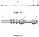
Figure 3A is a side view of a shaft assembly and a jaw assembly for an laparoscopic clip applier in accordance with the present invention; -
Figure 3B is a side detail view of the proximal end of the shaft assembly ofFigure 3A ; -
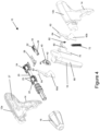
Figure 4 is an exploded perspective view of the handle assembly ofFigure 1 ; -
Figure 5 is a cut-away side view of the handle assembly ofFigure 1 with handles in a spaced apart configuration; -
Figure 6 is a cut-away side view of the handle assembly ofFigure 1 with a movable handle moved a first distance towards an approximated configuration; -
Figure 7 is a cut-away side view of the handle assembly ofFigure 1 with the movable handle moved the first distance and illustrating a ratchet mechanism; -
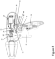
Figure 8 is a cut-away side view of the handle assembly ofFigure 1 with the movable handle moved the first distance and illustrating a geared actuation mechanism; -
Figure 9 is a cut-away side view of the handle assembly ofFigure 1 with a movable handle moved a second distance towards an approximated configuration; -
Figure 10 is a cut-away side view of the handle assembly ofFigure 1 with the movable handle moved the second distance and illustrating a ratchet mechanism; -
Figure 11 is a cut-away side view of the handle assembly ofFigure 1 with the movable handle moved the second distance and illustrating a geared actuation mechanism; -
Figure 12 is a cut-away side view of the handle assembly ofFigure 11 from an opposite side of the handle assembly; -
Figure 13 is a cut-away side view of the handle assembly ofFigure 1 with the movable handle returned to the spaced apart configuration; -
Figure 14 is a cut-away side view of the handle assembly ofFigure 13 from an opposite side of the handle assembly illustrating a geared actuation mechanism; -
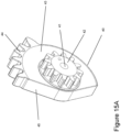
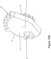
Figure 15A is a perspective view of an idler gear of the geared actuation mechanism ofFigure 14 ; -
Figure 15B is a perspective view of the idler gear ofFigure 15A ; -
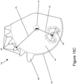
Figure 15C is a side view of the idler gear ofFigure 15A ; and -
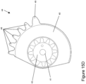
Figure 15D is a side view of the idler gear ofFigure 15C from an opposite side. - With reference to
Figures 1 and2 , ahandle assembly 10 for a laparoscopic clip applier in accordance with the present invention is illustrated. Thehandle assembly 10 can comprise ahandle body 12 extending from a proximal end to a distal end and defining a longitudinal axis of the handle assembly. Thehandle body 12 has astationary handle 14 and amovable handle 16 or trigger pivotably coupled to thestationary handle 14. Themovable handle 16 can be pivoted from a spaced apart or open configuration relative to thestationary handle 14 to an approximated or closed configuration. Thehandle assembly 10 further comprises a laparoscopic shaft interface at the distal end of thehandle body 12. The laparoscopic shaft interface can have arotatable collar 18 that is rotatable about the longitudinal axis to rotate a laparoscopic shaft and jaw assembly coupled to the laparoscopic shaft interface. - The
handle assembly 10 comprises a pistol-grip style handle with astationary handle 14 and amovable handle 16 coupled thereto. But, it is contemplated that other handle styles can include some or all of the features further described with respect to the illustrated pistol-grip handle. For example, the handle assembly can comprise a scissor-type handle, a generally in-line handle, or another handle style. - With reference to
Figures 3A and 3B , alaparoscopic shaft assembly 20 andjaw assembly 19 that can be used with the handle assembly ofFigure 1 is illustrated. The shaft extends generally longitudinally from a proximal end to a distal end. Ajaw assembly 19 comprising a pair of opposing jaws is disposed at the distal end. A central portion extends between the proximal end and the distal end. An actuation assembly is positioned at the proximal end. The jaw assembly is configured to receive a surgical clip when the jaws are in an open configuration with one jaw spaced apart from an opposing jaw. Once the jaw assembly has received the surgical clip, the jaws are clamped to a closed configuration in which the jaws are approximated to clamp the surgical clip. Thejaw assembly 19 can then be returned to the open configuration to receive another clip. - With continued reference to
Figures 3A and 3B , the central portion of theshaft assembly 20 comprises a generally tubular member extending from the proximal end to the distal end. The tubular member has a generally smooth outer surface to be positioned through a seal interface of a surgical access port such as a trocar cannula. A plurality of surgical clips can be positioned within the tubular member. Furthermore, the shaft assembly can comprise a mechanism for feeding the distal-most clip of the plurality of surgical clips to the jaw assembly and a mechanism for closing the jaws of the jaw assembly. The tubular member and jaw assembly can be sized for insertion through a surgical access port having a specific inner diameter. For example, the tubular member and jaw assembly can be sized for insertion through a 15mm, 12mm, 10mm, 8mm, or 5mm trocar cannula or a surgical access port having another inner diameter. - With continued reference to
Figures 3A and 3B , the proximal end of theshaft assembly 20 comprises the actuation assembly. When the shaft assembly is assembled with a surgical clip applier, the actuation assembly is positioned within the handle assembly. As illustrated, the actuation assembly comprises afirst slider 22 positioned at the distal end of the actuation assembly. The actuation assembly can further comprise asecond slider 24 positioned at the proximal end of the actuation assembly. The first andsecond sliders second sliders first slider 22 is coupled to the closure mechanism and thesecond slider 24 is coupled to the clip feed mechanism. It is contemplated that thefirst slider 22 can be coupled to the feed mechanism and thesecond slider 24 can be coupled to the closure mechanism and that the handle assembly can be configured to operate the first andsecond sliders - With reference to
Figure 3B , as illustrated, thesecond slider 24 is coupled to the feed mechanism within the shaft assembly. As thesecond sider 24 is advanced longitudinally distally by the handle assembly, a clip of the plurality of clips in the tubular member is loaded into the jaw assembly. Thesecond slider 24 is then retracted proximally by the handle assembly leaving the clip positioned in thejaw assembly 19. Retracting thesecond slider 24 proximally can also retract the feed mechanism from thejaw assembly 19 such that thejaw assembly 19 is able to be closed without interference from the feed mechanism. - With reference to
Figure 3B , as illustrated, thefirst slider 22 is coupled to the closure mechanism within the shaft assembly. When thefirst slider 22 is advanced longitudinally distally by the handle assembly, the closure mechanism is operated to approximate the jaws of the jaw assembly and compress the surgical clip loaded between the jaws of thejaw assembly 19. When thefirst slider 22 is retracted proximally, thejaw assembly 19 returns to the open configuration. - With reference to
Figure 4 , an exploded view of thehandle assembly 10 ofFigures 1 and2 is illustrated. Here, the handle body comprises twohousing halves stationary handle 14 can be formed integrally with the handle body. Themovable handle 16 can be pivotally coupled to thehousing halves - With continued reference to
Figure 4 , themovable handle 16 comprises a layered construction. As illustrated, themovable handle 16 comprises agrip member 68, afirst closure lever 60a, asecond closure lever 60b, and aratchet plate 70, all of which are layered together and rotatable about the pivot point. Thegrip member 68,first closure lever 60a,second closure lever 60b, and ratchetplate 70 are joined such that they rotate about the pivot point as a single unit. For example the individual layers of the movable handle can each include a keyed coupling to an adjacent layer. Alternatively, the individual layers can be fastened to one another with fasteners, adhesives, welding or other fusing techniques. Further, the movable handle can be integrally formed as a monolithic unit. - With continued reference to
Figure 4 , the handle assembly further comprises a feed mechanism having a gear train. The gear train comprises anidler gear 40, alongitudinal slider 50, and adrive plate 26. Theidler gear 40 is driven responsive to pivoting movement of themovable handle 16. Theidler gear 40 is rotatably coupled to thehandle body 12 and rotates about an axis that extends through an arcuate slot formed in themovable handle 16. Theidler gear 40 can comprise apinion gear portion 42 and at least one drive gear portion including a plurality ofgear teeth 44. Thepinion gear portion 42 is positioned to be driven by a plurality of drive gear teeth disposed on themovable handle 16. - With continued reference to
Figure 4 , theidler gear 40 is in geared engagement with thelongitudinal slider 50. Thus, rotation of theidler gear 40 responsive to pivotal motion of themovable handle 16 rotates the at least one drive gear portion of theidler gear 40, which engages a corresponding at least onerack portion 54 of thelongitudinal slider 50. Thelongitudinal slider 50 is positioned on alongitudinal shelf 27 within thehandle body 12 adjacent the actuation assembly. Accordingly, pivotal movement of themovable handle 16 is transmitted through the gear train of the feed mechanism to result in longitudinal sliding of thelongitudinal slider 50. - With continued reference to
Figure 4 , thelongitudinal slider 50 can include aprotrusion 52 that is engageable with thedrive plate 26. Thedrive plate 26 can be coupled to thesecond slider 24 such that with thelongitudinal slider 50 engaged with thedrive plate 26, longitudinal movement of thelongitudinal slider 50 correspondingly moves thesecond slider 24 of the actuation assembly. - The
first slider 22 of the actuation assembly is coupled to themovable handle 16 by a closure mechanism. The closure mechanism comprises thefirst closure lever 60a and thesecond closure lever 60b coupled to themovable handle 16. Thefirst closure lever 60a andsecond closure lever 60b are positioned laterally on opposite sides of thefirst slider 22. Thefirst closure lever 60a andsecond closure lever 60b each comprise a forked end having aclosure fork 62 and aretraction fork 64. Thefirst slider 22 comprises laterally-extending protrusions such aslugs 23 that can be engaged by the forked ends of the first and second closure levers 60a, 60b to longitudinally advance or retract thefirst slider 22 responsive to pivotal movement of themovable handle 16. - With continued reference to
Figure 4 , the handle assembly can further comprise a ratchet mechanism. The ratchet mechanism can be coupled to themovable handle 16 to prevent the movable handle from being released before a loaded clip has been clamped a predetermined amount. Advantageously, this ratchet mechanism can reduce the incidence of clip jams or unintended deployment of insufficiently clamped clips. The ratchet mechanism comprises theratchet plate 70 having aratchet rack 80 formed thereon and apawl 82 engageable with theratchet rack 80. Thepawl 82 is coupled to thehandle body 12 and is positioned to engage with theratchet rack 80 once themovable handle 16 has been pivoted an initial increment from an open configuration. - In operation in conjunction with a clip feeding and clamping cycle, once the
pawl 82 engages theratchet rack 80, the ratchet mechanism allows continued movement of themovable handle 16 towards the approximated configuration, but restricts movement of themovable handle 16 toward the open configuration. Once themovable handle 16 has been pivoted to feed a clip to the jaw assembly and clamp the clip a predetermined amount, thepawl 82 reaches an end of theratchet rack 80 and disengages from theratchet rack 80. With thepawl 82 disengaged from theratchet rack 80, themovable handle 16 can be released to pivot towards the open configuration. The handle assembly can include a biasing member such as atension spring 72 that biases themovable handle 16 towards the open configuration. - With reference to
Figures 5-12 , a complete clip feed and closure cycle of the handle assembly is illustrated. With reference toFigure 5 , a partial cut away view of the handle assembly illustrates the handle assembly with themovable handle 16 in an initial, open configuration. With the handle in the open configuration, the first andsecond sliders - With the handle assembly in the open configuration, the
closure fork 62 of the closure mechanism is disengaged from thefirst slider 22 of the actuation assembly. Rather, theretraction fork 64 of the closure mechanism can engage thefirst slider 22, with a fork gap between theretraction fork 64 and theclosure fork 62 separating theclosure fork 62 from thefirst slider 22. Accordingly, upon initial movement of themovable handle 16, theclosure lever 60 is directly pivoted by themovable handle 16, but the closure mechanism does not engage thefirst slider 22. - With the handle assembly in the open configuration, the
drive gear portion 44 of theidler gear 40 in the gear train of the feed mechanism is in meshed engagement with the correspondingdrive rack portion 54 of thelongitudinal slider 50. As illustrated, thelongitudinal slider 50 is in a proximal position. Upon initial movement of themovable handle 16, theidler gear 40 will rotate and advance thelongitudinal slider 50 distally. Additionally, with thelongitudinal slider 50 in the proximal position, theprotrusion 52 or fin of thelongitudinal slider 50 can engage thedrive plate 26. Thus, when thelongitudinal slider 50 is advanced distally, thedrive plate 26 andsecond slider 24 are correspondingly advanced distally. Thelongitudinal slider 50,drive plate 26, andsecond slider 24 can be biased to the proximal position by a biasing member such as atension spring 32 coupled to thehandle body 12. - In operation, as the
movable handle 16 is initially moved from the open configuration, illustrated inFigure 5 , towards the closed configuration, the closure mechanism is disengaged from thefirst slider 22, allowing the jaw assembly to remain in an open configuration. But, the feed mechanism is engaged with thesecond slider 24, and thelongitudinal slider 50 longitudinally distally advances thesecond slider 24 of the actuation assembly to load a clip into the jaw assembly. Thehandle body 12 can comprise at least oneguide 30 positioned to maintain thedrive plate 26 in engagement with the protrudingfin 52 of thelongitudinal slider 50 during the initial movement of thelongitudinal slider 50. - With reference to
Figure 6 , once themovable handle 16 has been moved a first distance from the open configuration, theclosure fork 62 of theclosure lever 60 engages thefirst slider 22 of the actuation assembly such that movement of themovable handle 16 beyond the first distance will longitudinally advance thefirst slider 22 to close the jaw assembly. Accordingly, movement of themovable handle 16 the first distance operates the feed mechanism to load a surgical clip that can then be clamped once themovable handle 16 is moved beyond the first distance. Thus, the feed mechanism of the handle assembly can be configured to disengage from thesecond slider 24 of the actuation assembly once the clip has been fed. - With reference to
Figure 6 , the handle assembly can include aramp 28 positioned and configured to disengage thedrive plate 26 from theprotrusion 52 or fin of thelongitudinal slider 50. As thedrive plate 26 is longitudinally advanced to engage theramp 28 of the handle assembly, the distal end of thedrive plate 26 is lifted to flex thedrive plate 26. Once thedrive plate 26 has been sufficiently flexed by the ramp, thedrive plate 26 is lifted out of engagement with the fin of thelongitudinal slider 50. With thesecond slider 24 of the actuation assembly disengaged from thelongitudinal slider 50, a biasing member such as thetension spring 32, can rapidly withdraw thesecond slider 24 proximally. The feed mechanism of the handle assembly can be configured to completely load a clip and withdraw a feed member from the jaw assembly before the feed member can interfere with closure of the jaws. Thus, advantageously, the feed mechanism of the handle assembly can be configured to reduce the potential for clip feed jams. - With reference to
Figure 7 , a partial cut away view of the handle assembly is illustrated with the first clamp lever removed to further illustrate certain aspects of the handle assembly. The handle assembly may further comprise a ratchet mechanism to coordinate operation of the handle assembly to reduce the potential for clip feed jams. The ratchet mechanism can facilitate actuation of the movable handle through a complete actuation stroke corresponding to a complete clip feed and closure cycle of the feed and closure mechanisms before the movable handle can be returned to the open configuration for feed and closure of a subsequent clip. - With continued reference to
Figure 7 , the illustrated ratchet mechanism comprises aratchet rack 80 positioned on a ratchet plate that is coupled to themovable handle 16. The ratchet mechanism further comprises aratchet pawl 82 coupled to the handle assembly. The ratchet mechanism can further include apawl spring 84 coupling the ratchet pawl to the handle assembly to bias theratchet pawl 82 into engagement with theratchet rack 80 to provide a one-way ratchet mechanism. Once themovable handle 16 has been moved a predetermined distance from the open configuration towards the closed configuration, theratchet pawl 82 engages a first tooth of theratchet rack 80 such that themovable handle 16 can continue to move towards the closed configuration but is prevented from moving towards the open configuration by the ratchet mechanism. - With reference to
Figure 8 , a partial cut away view of the handle assembly is illustrated with the grip member removed to further illustrate certain aspects of the handle assembly. As illustrated, theidler gear 40 comprises apinion gear portion 42 positioned to engage a drive rack formed in a slot in the grip member. Theidler gear 40 further comprises a first plurality ofdrive teeth 44 formed on an outer edge thereof that engage afirst drive rack 54 on thelongitudinal slider 50. The feed mechanism comprises a gear train having sequentially-engageable gearing to define corresponding sequential longitudinal slider advancement profiles. For example, theidler gear 40 comprises a first plurality ofdrive teeth 44 formed on an outer edge thereof that define a first advancement profile of the longitudinal slider defined by the longitudinal slider advancing a first longitudinal distance per degree of rotation of the movable handle and a second plurality of drive teeth that define a second advancement profile of the longitudinal slider. - With continued reference to
Figure 8 , once thelongitudinal slider 50 has been advanced the first distance, a second plurality of drive teeth 46 (Figure 12 ) engage asecond drive rack 56 on thelongitudinal slider 50 to define a second advancement profile of thelongitudinal slider 50. The second plurality ofdrive teeth 46 can be formed on a surface of the idler gear opposite the pinion gear or the second plurality ofdrive teeth 46 can be positioned radially inwardly of the first plurality ofdrive teeth 44 with respect to the rotational axis of theidler gear 40. Thesecond drive rack 56 can likewise be positioned to engage the radially-inwardly positioned drive teeth. With radial inward positioning, movement of the movable handle a given distance results in a second advancement profile defined by a relatively smaller longitudinal translation of the longitudinal slider per rotation of themovable handle 16 when thesecond drive rack 56 is engaged with the second plurality ofdrive teeth 46 as compared to when thefirst drive rack 54 is engaged with the first plurality ofdrive teeth 44. Advantageously, the sequentially-engageable gearing can reduce the total longitudinal translation of the longitudinal slider as the movable handle is actuated from the open configuration to the closed configuration. Thus, desirably, the handle body can have a relatively compact length enhancing usability and reducing packaging and storage requirements. - The sequentially-engageable gearing of the gear train can comprise a transition region to facilitate a smooth transition from engagement of the first plurality of
drive teeth 44 with thefirst drive rack 54 to engagement of the second plurality ofdrive teeth 46 with thesecond drive rack 56. For example, the first plurality ofdrive teeth 44 comprises a plurality of teeth having a first size and at least one transition tooth having a second size larger than the first size. Thefirst drive rack 54 comprises a corresponding plurality of teeth arranged to receive the plurality of teeth having the first size and at least one tooth arranged to receive the at least one transition tooth of the first plurality of drive teeth. The relatively large size of the at least one transition tooth maintains geared engagement between thelongitudinal slider 50 and theidler gear 40 throughout a transition from the first plurality ofdrive teeth 44 andfirst drive rack 54 and the second plurality ofdrive teeth 46 and thesecond drive rack 56. - With reference to
Figure 9 , a handle assembly is illustrated with themovable handle 16 approaching a closed configuration. As illustrated, thesecond slider 24 of the actuation mechanism has been disengaged from the feed mechanism and proximally withdrawn by thetension spring 32. In certain arrangements with a sequentially-engageable gearing, the second plurality of drive teeth of the idler gear has engaged the second rack of thelongitudinal slider 50 of the feed mechanism. Accordingly, continued movement of themovable handle 16 past the first distance to feed a clip moves the longitudinal slider 50 a relatively short distance relative to the handle body. - With continued reference to
Figure 9 , themovable handle 16 of the illustrated handle assembly is approaching the closed configuration having moved a second distance beyond the first distance. Over the second distance, theclosure fork 62 of theclosure lever 60 has advanced thefirst slider 22 of the actuation assembly to clamp a clip positioned in the jaw assembly. Advantageously, thefirst slider 22 is directly connected to themovable handle 16 at thelug 23 of thefirst slider 22, providing tactile feedback to the user as the clip is clamped. - With reference to
Figure 10 , a partial cut-away view of the handle assembly is illustrated with the first closure lever hidden to illustrate certain aspects of the handle assembly. As illustrated, with themovable handle 16 approaching the closed configuration, theratchet pawl 82 of the ratchet mechanism can be approaching a last tooth of theratchet rack 80 positioned on aratchet plate 70 of themovable handle 16. Once theratchet pawl 82 has been advanced past the last tooth of theratchet rack 80, themovable handle 16 can be returned to the open configuration without restriction from the ratchet mechanism. In various configurations, the ratchet mechanism can be configured such thatratchet pawl 82 passes the last tooth of theratchet rack 80 only after the clip has been substantially fully closed. Alternatively, the ratchet mechanism can be configured such that theratchet pawl 82 passes the last tooth of theratchet rack 80 once the clip has been partially closed. - With continued reference to
Figure 10 , themovable handle 16 can comprise anarcuate slot 66 formed therethrough to accommodate arotational hub 41 of theidler gear 40. Accordingly, theidler gear 40 can be rotatably coupled to both handle halves of the handle body such as by a pinned connection extending through themovable handle 16. Thearcuate slot 66 can have ends defining an actuation stroke from an open configuration of themovable handle 16 to a closed configuration of themovable handle 16. Alternatively, thearcuate slot 66 can have a length that is longer than the actuation stroke of themovable handle 16, such that theslot 66 has ends that are spaced apart from therotational hub 41 of theidler gear 40 when themovable handle 16 is in the open configuration or the closed configuration. - With reference to
Figure 11 , a partial cut-away view of the handle assembly is illustrated with the first closure lever and grip member hidden to illustrate certain aspects of the handle assembly. As illustrated, the second plurality ofgear teeth 46 of theidler gear 40 is engaged with the second rack on thelongitudinal slider 50. Moreover the first plurality ofgear teeth 44 of theidler gear 40 is disengaged from thefirst rack 54 on thelongitudinal slider 50.Figure 12 illustrates a partial cut-away view of the handle assembly from an opposite side of the handle assembly. As illustrated, the second plurality ofgear teeth 46 is disposed on a face of theidler gear 40 opposite the pinion gear portion. Moreover, the second plurality ofgear teeth 46 is positioned at a second radial distance R2 from the rotational axis of theidler gear 40. Thesecond rack 56 is positioned on thelongitudinal slider 50 to engage the second plurality ofdrive teeth 46. The second radial distance R2 is relatively small compared to a first radial distance R1 of the first plurality of drive teeth 44 (Figure 11 ). - With reference to
Figure 13 , a handle assembly is illustrated with the movable handle returned to the open configuration. Once a clip feed and closure cycle has been completed, as illustrated inFigures 5-12 , themovable handle 16 can be released to return themovable handle 16 to the open configuration. A biasing member such as ahandle spring 72 can bias themovable handle 16 into the open configuration. As themovable handle 16 is moving towards the open configuration, theretraction fork 64 of the closure lever can proximally retract thefirst slider 22 of the actuation assembly. This retraction of thefirst slider 22 opens the jaws of the jaw assembly. Additionally, while the movable handle is moving towards the open configuration, it rotates theidler gear 40, which returns thelongitudinal slider 50 proximally to the proximal position. As thelongitudinal slider 50 nears the proximal position, theprotrusion 52 fin of thelongitudinal slider 50 engages thedrive plate 26. The fin on thelongitudinal slider 50 can include a tapered or ramped profile at the proximal end thereof to guide thedrive plate 26 into a flexed configuration and into engagement with the fin. Thus, once the handle assembly has been returned to the open configuration, the feed mechanism is engaged with thesecond slider 24 to feed a subsequent clip when the movable handle is subsequently closed. - With reference to
Figure 14 , a partial cut away of a handle assembly is illustrated with the second clamp lever hidden to visualize certain aspects of the handle assembly. As illustrated, themovable handle 16 comprises adrive rack 74 formed therein that engages the pinion gear portion of theidler gear 40. Thedrive rack 74 can be positioned in arecess 76 or slot formed in thegrip member 68 of themovable handle 16. The recess can 76 have a generally arcuate profile such that themovable handle 16 can be pivotally moved relative to the handle body and the rotational axis of theidler gear 40. Thedrive rack 74 is positioned in arecess 76 formed in thegrip member 68 of themovable handle 16. As illustrated, thegrip member 68 also includes anarcuate slot 66 formed through therecess 76 to accommodate a rotational coupling, such as a pivot pin, of theidler gear 40 to the handle assembly. - With reference to
Figures 15A-D , anidler gear 40 for the handle assemblies discussed herein is illustrated. The illustratedidler gear 40 is configured to provide sequentially-engageable gearing. Accordingly, theidler gear 40 includes apinion gear portion 42 positioned on afirst surface 43 thereof, a first plurality ofgear teeth 44 positioned on anedge 45 thereof, and a second plurality ofteeth 46 positioned on asecond surface 47 thereof opposite thefirst surface 43. Theidler gear 40 further comprises arotational hub 41 extending through thepinion gear portion 42. - With continued reference to
Figures 15A-D , the sequentially-engageable gearing profile of the illustratedidler gear 40 includes one plurality of gear teeth at a rotational radius that is relatively large compared to the rotational radius of the other plurality of gear teeth, allowing the longitudinal slider to be driven along an advancement profile that can vary relative to an input rotation of the pinion gear portion. For example, the first plurality ofgear teeth 44 can be positioned at a first radial distance R1 from therotational hub 41, and the second plurality of gear teeth can be positioned at a second radial distance R2 from therotational hub 41, smaller than the first radial distance R1. (Figure 15C ). In other arrangements of handle assembly, other arrangements of idler gear can be used. For example, the positions of the pinion, first, and second plurality of drive teeth on the surfaces and edge of the idler gear can be varied from that illustrated. - The sequentially-engageable gearing of the
idler gear 40 comprises a transition region to facilitate a smooth transition from engagement of the first plurality ofdrive teeth 44 with the first drive rack to engagement of the second plurality ofdrive teeth 46 with the second drive rack. One of the plurality ofdrive teeth drive teeth 44 comprises a plurality ofteeth 48 having a first size and at least onetransition tooth 49 having a second size larger than the first size. The first drive rack comprises a corresponding plurality of teeth arranged to receive the plurality of teeth having the first size and at least one tooth arranged to receive the at least onetransition tooth 49 of the first plurality ofdrive teeth 44. The second plurality ofdrive teeth 46 includes a plurality of teeth having a generally symmetric configuration such that each tooth has a substantially identical geometric profile. It is contemplated that the second plurality ofdrive teeth 46 can also have an asymmetric profile including a transition tooth having a different size instead of or in addition to thetransition tooth 49 on the first plurality ofdrive teeth 44. - The handle assemblies described herein can be configured to provide a desired operating sequence. For example, the movable handle can be pivotable over an approximately 40 degree actuation stroke from an open configuration to a closed configuration. The feed mechanism is actuated over approximately the first 18 degrees of the actuation stroke to load a clip into the jaw assembly. The closure mechanism is actuated over the remaining 22 degrees of the actuation stroke. Advantageously, the geared clip feed mechanism allows a clip to be loaded with a relatively constant force profile compared to a lever-actuated loading mechanism, enhancing user operability. Moreover, the direct connection of the movable handle to the front slider via the lever enhances user feel during the clip clamping portion of the actuation stroke. Alternatively, the actuation stroke, feed mechanism portion, and closure mechanism portion can have other arc lengths as may be desired to configure the handle to have a desired clip load force, user feedback, or to house the feed and closure mechanisms in a desired handle assembly size and shape.
- Although this application discloses certain preferred embodiments and examples, it will be understood by those skilled in the art that other alternative embodiments and/or uses of the invention and obvious modifications and equivalents thereof may be apparent to those skilled in the art, which may fall within the scope of the present invention as defined by the following claims.
Claims (15)
- A laparoscopic clip applier comprising:a jaw assembly (19) comprising a pair of opposed jaws configured to receive and clamp a surgical clip;a shaft assembly (20) extending from a proximal end to a distal end, the jaw assembly (19) positioned at the distal end of the shaft assembly (20), and the shaft assembly (20) comprising a first slider (22) and a second slider (24) at the proximal end, the first and second slider being configured to actuate clip feed and closure mechanisms within the shaft assembly; anda handle assembly (10) comprising:a stationary handle (14);a movable handle (16) pivotably coupled to the stationary handle (14);a first actuation mechanism coupled to the movable handle (16) and to the first slider (22); anda second actuation mechanism, the second actuation mechanism comprising:a gear (40) rotatably driven by pivotal movement of the movable handle (16), the gear (40) having a first plurality of teeth (44) and a second plurality of teeth (46); anda longitudinal slider (50) having a first rack (54) engageable with the first plurality of teeth (44); the longitudinal slider (50) being engageable with the second slider (24) of the shaft assembly (20);the first plurality of teeth defining a first advancement profile of the longitudinal slider defined by the longitudinal slider advancing a first longitudinal distance per degree of rotation of the movable handle;characterized in that the longitudinal slider (50) comprises a second rack (56) sequentially engageable with the second plurality of teeth (46);wherein once the longitudinal slider has been advanced a first distance, the second plurality of drive teeth engage the second drive rack on the longitudinal slider (50) to define a second advancement profile of the longitudinal slider.
- The laparoscopic surgical clip applier of claim 1, wherein the first slider is a clamping slider, the second slider is a feed slider, the second actuation mechanism is a feed mechanism and the first actuation mechanism is a clamping actuator coupled to the movable handle (16), the clamping actuator comprising:a clamping arm (62) extending from the clamping actuator and configured to distally advance the first slider (22); anda return arm (64) extending from the clamping actuator and configured to proximally retract the first slider (22), wherein the clamping arm (62) is spaced apart from the return arm (64).
- The laparoscopic surgical clip applier of claim 2, wherein the clamping actuator extends from the movable handle (16).
- The laparoscopic surgical clip applier of claim 2, wherein the gear (40) is coupled to the stationary handle (14) at a rotational axis and wherein the movable handle (16) comprises a slot (66) formed therein to receive the gear (40) at the rotational axis.
- The laparoscopic surgical clip applier of claim 4, wherein the slot (66) of the movable handle (16) comprises a feed mechanism rack (74) formed therein.
- The laparoscopic surgical clip applier of claim 5, wherein the gear (40) comprises a drive pinion gear (42) engaged with the feed mechanism rack (74) of the movable handle (16).
- The laparoscopic surgical clip applier of claim 2, wherein the gear (40) comprises a plate having a first surface (43), a second surface (47) opposite the first surface (43) and an edge (45) extending between the first surface (43) and the second surface (47) and wherein the first plurality of drive teeth (44) is positioned on one of the first surface (43), the second surface (47), and the edge (45) and the second plurality of drive teeth (46) is positioned on another of the first surface (43), the second surface (47), and the edge (45).
- The laparoscopic surgical clip applier of claim 7, wherein the gear (40) further comprises a drive pinion gear (42) positioned on one of the first surface (43), the second surface (47), and the edge (45) not having the first plurality of drive teeth (44) and the second plurality of drive teeth (48).
- The laparoscopic surgical clip applier of claim 2, wherein the second slider (24) is coupled to a flexible drive plate (26) and wherein the longitudinal slider (50) comprises a tab (52) engageable with the flexible drive plate (26).
- The laparoscopic surgical clip applier of claim 9, wherein the handle assembly further comprises a ramp positioned to deflect the flexible drive plate (26) out of engagement with the tab (52) of the longitudinal slider (50) once the longitudinal slider has been longitudinally advanced a predetermined distance.
- The laparoscopic surgical clip applier of claim 10, wherein the second actuation mechanism further comprises a return spring (32) biasing the second slider (24) into a retracted position when the flexible drive plate (26) has been disengaged from the tab (52) of the longitudinal slider (50).
- The laparoscopic surgical clip applier of claim 10, wherein the clamping arm (62) engages the clamping slider (22) once the longitudinal slider (50) has been longitudinally advanced the predetermined distance.
- The laparoscopic clip applier of claim 1, wherein the first actuation mechanism comprises a forked actuator (60) having a first arm to longitudinally advance the first slider (22) and a second arm to longitudinally retract the first slider (22).
- The laparoscopic clip applier of claim 1, wherein the first plurality of teeth (44) have a first pitch diameter and the second plurality of teeth (46) have a second pitch diameter different from the first pitch diameter.
- The laparoscopic clip applier of claim 1, wherein the first plurality of teeth (44) comprise at least one tooth (49) having a transition profile.
Applications Claiming Priority (2)
| Application Number | Priority Date | Filing Date | Title |
|---|---|---|---|
| US201662325541P | 2016-04-21 | 2016-04-21 | |
| PCT/US2017/028813 WO2017184964A1 (en) | 2016-04-21 | 2017-04-21 | Laparoscopic clip applier |
Publications (3)
| Publication Number | Publication Date |
|---|---|
| EP3445256A1 EP3445256A1 (en) | 2019-02-27 |
| EP3445256B1 true EP3445256B1 (en) | 2024-01-10 |
| EP3445256C0 EP3445256C0 (en) | 2024-01-10 |
Family
ID=58664851
Family Applications (1)
| Application Number | Title | Priority Date | Filing Date |
|---|---|---|---|
| EP17720989.7A Active EP3445256B1 (en) | 2016-04-21 | 2017-04-21 | Laparoscopic clip applier |
Country Status (7)
| Country | Link |
|---|---|
| US (1) | US10405862B2 (en) |
| EP (1) | EP3445256B1 (en) |
| JP (1) | JP6931360B2 (en) |
| KR (1) | KR102303576B1 (en) |
| AU (1) | AU2017252440A1 (en) |
| CA (1) | CA3021683A1 (en) |
| WO (1) | WO2017184964A1 (en) |
Families Citing this family (7)
| Publication number | Priority date | Publication date | Assignee | Title |
|---|---|---|---|---|
| CN109770996B (en) * | 2019-02-26 | 2021-08-06 | 袁守娴 | Multifunctional operation grasping forceps for laparoscope |
| US11524398B2 (en) * | 2019-03-19 | 2022-12-13 | Covidien Lp | Gear drive mechanisms for surgical instruments |
| CN110507388A (en) * | 2019-08-07 | 2019-11-29 | 深圳市罗伯医疗科技有限公司 | A kind of flexible mechanical arm and interior mirror assembly |
| CN112704539B (en) * | 2019-10-25 | 2023-02-24 | 苏州英途康医疗科技有限公司 | Clip applier shaft assembly and medical surgical clip applier |
| KR20220123277A (en) | 2019-12-31 | 2022-09-06 | 어플라이드 메디컬 리소시스 코포레이션 | 2 piece clip applier jaw assembly and manufacturing method |
| US10993764B1 (en) | 2020-01-14 | 2021-05-04 | Microline Surgical, Inc. | Insulating grips for minimally invasive surgical instruments |
| CN113796915B (en) * | 2021-11-19 | 2022-02-22 | 杭州康基医疗器械有限公司 | Cam control mechanism of repeating clip applier |
Family Cites Families (49)
| Publication number | Priority date | Publication date | Assignee | Title |
|---|---|---|---|---|
| US4850355A (en) * | 1987-04-06 | 1989-07-25 | Richard-Allan Medical Industries, Inc. | Hemostatic clip applicator for applying multiple hemostatic clips |
| US5030226A (en) | 1988-01-15 | 1991-07-09 | United States Surgical Corporation | Surgical clip applicator |
| US5197970A (en) | 1988-01-15 | 1993-03-30 | United States Surgical Corporation | Surgical clip applicator |
| US5171249A (en) | 1991-04-04 | 1992-12-15 | Ethicon, Inc. | Endoscopic multiple ligating clip applier |
| US5858018A (en) * | 1993-08-25 | 1999-01-12 | Apollo Camera, Llc | Low profile tool for applying spring action ligation clips |
| US5607436A (en) | 1993-10-08 | 1997-03-04 | United States Surgical Corporation | Apparatus for applying surgical clips |
| US5700271A (en) | 1995-10-20 | 1997-12-23 | United States Surgical Corporation | Apparatus for applying surgical clips |
| US5582615A (en) | 1995-10-30 | 1996-12-10 | Pilling Weck, Incorporated | Handle for surgical clip applicator systems |
| US6099537A (en) * | 1996-02-26 | 2000-08-08 | Olympus Optical Co., Ltd. | Medical treatment instrument |
| JPH09224948A (en) * | 1996-02-26 | 1997-09-02 | Olympus Optical Co Ltd | Treatment tool |
| JPH09262243A (en) * | 1996-03-28 | 1997-10-07 | Olympus Optical Co Ltd | Suture apparatus |
| JPH09224947A (en) * | 1996-02-26 | 1997-09-02 | Olympus Optical Co Ltd | Clip applier |
| US5782844A (en) | 1996-03-05 | 1998-07-21 | Inbae Yoon | Suture spring device applicator |
| US5830221A (en) | 1996-09-20 | 1998-11-03 | United States Surgical Corporation | Coil fastener applier |
| US6425900B1 (en) | 2000-10-19 | 2002-07-30 | Ethicon Endo-Surgery | Method for attaching hernia mesh |
| US6551333B2 (en) | 2000-10-19 | 2003-04-22 | Ethicon Endo-Surgery, Inc. | Method for attaching hernia mesh |
| US6572626B1 (en) | 2000-10-19 | 2003-06-03 | Ethicon Endo-Surgery, Inc. | Surgical instrument having a fastener delivery mechanism |
| AU2004249161B9 (en) | 2003-06-13 | 2010-04-08 | Covidien Lp | Multiple member interconnect for surgical instrument and absorbable screw fastener |
| US7875040B2 (en) | 2003-10-15 | 2011-01-25 | Femcare Limited | Visual indication of a trigger intermediate position on an applicator |
| FR2876020B1 (en) | 2004-10-06 | 2007-03-09 | Sofradim Production Sa | APPARATUS FOR STORAGE, DISTRIBUTION AND INSTALLATION OF SURGICAL ATTACHES |
| AU2005294209B2 (en) * | 2004-10-08 | 2011-04-07 | Covidien Lp | Endoscopic surgical clip applier |
| US8038686B2 (en) | 2005-04-14 | 2011-10-18 | Ethicon Endo-Surgery, Inc. | Clip applier configured to prevent clip fallout |
| US7731724B2 (en) | 2005-04-14 | 2010-06-08 | Ethicon Endo-Surgery, Inc. | Surgical clip advancement and alignment mechanism |
| US7686820B2 (en) | 2005-04-14 | 2010-03-30 | Ethicon Endo-Surgery, Inc. | Surgical clip applier ratchet mechanism |
| US8523882B2 (en) | 2005-04-14 | 2013-09-03 | Ethicon Endo-Surgery, Inc. | Clip advancer mechanism with alignment features |
| US7297149B2 (en) | 2005-04-14 | 2007-11-20 | Ethicon Endo-Surgery, Inc. | Surgical clip applier methods |
| US7740641B2 (en) | 2005-04-14 | 2010-06-22 | Ethicon Endo-Surgery, Inc. | Clip applier with migrational resistance features |
| US7288098B2 (en) | 2005-04-14 | 2007-10-30 | Ethicon Endo-Surgery, Inc. | Force limiting mechanism for medical instrument |
| US7261724B2 (en) | 2005-04-14 | 2007-08-28 | Ethicon Endo-Surgery, Inc. | Surgical clip advancement mechanism |
| US20070049949A1 (en) | 2005-08-25 | 2007-03-01 | Microline Pentax Inc | Clip feeder mechanism for clip applying device |
| US8080004B2 (en) | 2005-10-26 | 2011-12-20 | Earl Downey | Laparoscopic surgical instrument |
| US7862573B2 (en) | 2006-04-21 | 2011-01-04 | Darois Roger E | Method and apparatus for surgical fastening |
| US9017345B2 (en) | 2006-10-06 | 2015-04-28 | Covidien Lp | Coil fastener applier with flexible shaft |
| AU2008230841B2 (en) | 2007-03-26 | 2013-09-12 | Covidien Lp | Endoscopic surgical clip applier |
| US8021375B2 (en) | 2008-04-21 | 2011-09-20 | Conmed Corporation | Surgical clip applicator |
| US20100023026A1 (en) * | 2008-07-25 | 2010-01-28 | Zeiner Mark S | Reloadable laparoscopic fastener deploying device with disposable cartridge for use in a gastric volume reduction procedure |
| US8465502B2 (en) | 2008-08-25 | 2013-06-18 | Covidien Lp | Surgical clip applier and method of assembly |
| US8409223B2 (en) | 2008-08-29 | 2013-04-02 | Covidien Lp | Endoscopic surgical clip applier with clip retention |
| US8728098B2 (en) | 2009-05-12 | 2014-05-20 | Ethicon, Inc. | Surgical fasteners, applicator instruments, and methods for deploying surgical fasteners |
| US8920439B2 (en) | 2009-05-12 | 2014-12-30 | Ethicon, Inc. | Applicator instruments having curved and articulating shafts for deploying surgical fasteners and methods therefor |
| US8728099B2 (en) | 2009-05-12 | 2014-05-20 | Ethicon, Inc. | Surgical fasteners, applicator instruments, and methods for deploying surgical fasteners |
| US8579920B2 (en) | 2009-05-12 | 2013-11-12 | Ethicon, Inc. | Surgical fasteners, applicator instruments, and methods for deploying surgical fasteners |
| US8267945B2 (en) | 2009-10-09 | 2012-09-18 | Ethicon Endo-Surgery, Inc. | Clip advancer with lockout mechanism |
| US8262679B2 (en) | 2009-10-09 | 2012-09-11 | Ethicon Endo-Surgery, Inc. | Clip advancer |
| US8403945B2 (en) * | 2010-02-25 | 2013-03-26 | Covidien Lp | Articulating endoscopic surgical clip applier |
| CN201683954U (en) * | 2010-05-05 | 2010-12-29 | 王水良 | Disposable automatic continuous-running titanium clamp |
| AU2012202748A1 (en) * | 2011-06-21 | 2013-01-17 | Ethicon Endo-Surgery, Inc. | A surgical stapler having an adjustment feature |
| US8518055B1 (en) | 2012-05-11 | 2013-08-27 | Ethicon, Inc. | Applicator instruments for dispensing surgical fasteners during open repair procedures |
| FR3013206B1 (en) * | 2013-11-18 | 2015-12-11 | Galiana Jean Marc | MULTIFUNCTIONAL RECHARGEABLE AND DISPOSABLE SURGICAL DEVICE |
-
2017
- 2017-04-21 EP EP17720989.7A patent/EP3445256B1/en active Active
- 2017-04-21 AU AU2017252440A patent/AU2017252440A1/en not_active Abandoned
- 2017-04-21 US US15/493,682 patent/US10405862B2/en active Active
- 2017-04-21 WO PCT/US2017/028813 patent/WO2017184964A1/en active Application Filing
- 2017-04-21 JP JP2018554705A patent/JP6931360B2/en active Active
- 2017-04-21 CA CA3021683A patent/CA3021683A1/en not_active Abandoned
- 2017-04-21 KR KR1020187033761A patent/KR102303576B1/en active IP Right Grant
Also Published As
| Publication number | Publication date |
|---|---|
| JP6931360B2 (en) | 2021-09-01 |
| WO2017184964A1 (en) | 2017-10-26 |
| CA3021683A1 (en) | 2017-10-26 |
| KR102303576B1 (en) | 2021-09-23 |
| JP2019514478A (en) | 2019-06-06 |
| US20170303921A1 (en) | 2017-10-26 |
| EP3445256A1 (en) | 2019-02-27 |
| US10405862B2 (en) | 2019-09-10 |
| AU2017252440A1 (en) | 2018-10-18 |
| EP3445256C0 (en) | 2024-01-10 |
| KR20180137539A (en) | 2018-12-27 |
Similar Documents
| Publication | Publication Date | Title |
|---|---|---|
| EP3445256B1 (en) | Laparoscopic clip applier | |
| US11918231B2 (en) | Articulating endoscopic surgical clip applier | |
| US10932790B2 (en) | Geared actuation mechanism and surgical clip applier including the same | |
| US11298135B2 (en) | Endoscopic reposable surgical clip applier | |
| US10786262B2 (en) | Endoscopic reposable surgical clip applier | |
| US10610236B2 (en) | Endoscopic reposable surgical clip applier | |
| US20190046202A1 (en) | Geared actuation mechanism and surgical clip applier including the same | |
| US10660723B2 (en) | Endoscopic reposable surgical clip applier | |
| US10722236B2 (en) | Endoscopic reposable surgical clip applier | |
| US20170340325A1 (en) | Endoscopic reposable surgical clip applier | |
| US10010309B2 (en) | Surgical device with overload mechanism |
Legal Events
| Date | Code | Title | Description |
|---|---|---|---|
| STAA | Information on the status of an ep patent application or granted ep patent |
Free format text: STATUS: UNKNOWN |
|
| STAA | Information on the status of an ep patent application or granted ep patent |
Free format text: STATUS: THE INTERNATIONAL PUBLICATION HAS BEEN MADE |
|
| PUAI | Public reference made under article 153(3) epc to a published international application that has entered the european phase |
Free format text: ORIGINAL CODE: 0009012 |
|
| STAA | Information on the status of an ep patent application or granted ep patent |
Free format text: STATUS: REQUEST FOR EXAMINATION WAS MADE |
|
| 17P | Request for examination filed |
Effective date: 20180926 |
|
| AK | Designated contracting states |
Kind code of ref document: A1 Designated state(s): AL AT BE BG CH CY CZ DE DK EE ES FI FR GB GR HR HU IE IS IT LI LT LU LV MC MK MT NL NO PL PT RO RS SE SI SK SM TR |
|
| AX | Request for extension of the european patent |
Extension state: BA ME |
|
| RIN1 | Information on inventor provided before grant (corrected) |
Inventor name: MCCARTHY, ANDREW, J. Inventor name: WHITLOCK, MICHAEL Inventor name: PATEL, ATAL, C. Inventor name: ELLIOTT, PATRICK |
|
| DAV | Request for validation of the european patent (deleted) | ||
| DAX | Request for extension of the european patent (deleted) | ||
| STAA | Information on the status of an ep patent application or granted ep patent |
Free format text: STATUS: EXAMINATION IS IN PROGRESS |
|
| 17Q | First examination report despatched |
Effective date: 20200227 |
|
| STAA | Information on the status of an ep patent application or granted ep patent |
Free format text: STATUS: EXAMINATION IS IN PROGRESS |
|
| GRAP | Despatch of communication of intention to grant a patent |
Free format text: ORIGINAL CODE: EPIDOSNIGR1 |
|
| STAA | Information on the status of an ep patent application or granted ep patent |
Free format text: STATUS: GRANT OF PATENT IS INTENDED |
|
| INTG | Intention to grant announced |
Effective date: 20230807 |
|
| RIN1 | Information on inventor provided before grant (corrected) |
Inventor name: MCCARTHY, ANDREW, J. Inventor name: ELLIOTT, PATRICK Inventor name: WHITLOCK, MICHAEL Inventor name: PATEL, ATAL, C. |
|
| GRAS | Grant fee paid |
Free format text: ORIGINAL CODE: EPIDOSNIGR3 |
|
| GRAA | (expected) grant |
Free format text: ORIGINAL CODE: 0009210 |
|
| STAA | Information on the status of an ep patent application or granted ep patent |
Free format text: STATUS: THE PATENT HAS BEEN GRANTED |
|
| AK | Designated contracting states |
Kind code of ref document: B1 Designated state(s): AL AT BE BG CH CY CZ DE DK EE ES FI FR GB GR HR HU IE IS IT LI LT LU LV MC MK MT NL NO PL PT RO RS SE SI SK SM TR |
|
| REG | Reference to a national code |
Ref country code: GB Ref legal event code: FG4D |
|
| REG | Reference to a national code |
Ref country code: CH Ref legal event code: EP |
|
| REG | Reference to a national code |
Ref country code: DE Ref legal event code: R096 Ref document number: 602017078316 Country of ref document: DE |
|
| REG | Reference to a national code |
Ref country code: IE Ref legal event code: FG4D |
|
| U01 | Request for unitary effect filed |
Effective date: 20240110 |
|
| U07 | Unitary effect registered |
Designated state(s): AT BE BG DE DK EE FI FR IT LT LU LV MT NL PT SE SI Effective date: 20240115 |