EP3445142A1 - Elektronische ausstattung eines schienenfahrzeugs - Google Patents
Elektronische ausstattung eines schienenfahrzeugs Download PDFInfo
- Publication number
- EP3445142A1 EP3445142A1 EP18187991.7A EP18187991A EP3445142A1 EP 3445142 A1 EP3445142 A1 EP 3445142A1 EP 18187991 A EP18187991 A EP 18187991A EP 3445142 A1 EP3445142 A1 EP 3445142A1
- Authority
- EP
- European Patent Office
- Prior art keywords
- flange
- cooling module
- electronic equipment
- electronic
- electronic components
- Prior art date
- Legal status (The legal status is an assumption and is not a legal conclusion. Google has not performed a legal analysis and makes no representation as to the accuracy of the status listed.)
- Granted
Links
Images

Classifications
-
- H—ELECTRICITY
- H05—ELECTRIC TECHNIQUES NOT OTHERWISE PROVIDED FOR
- H05K—PRINTED CIRCUITS; CASINGS OR CONSTRUCTIONAL DETAILS OF ELECTRIC APPARATUS; MANUFACTURE OF ASSEMBLAGES OF ELECTRICAL COMPONENTS
- H05K7/00—Constructional details common to different types of electric apparatus
- H05K7/20—Modifications to facilitate cooling, ventilating, or heating
- H05K7/2089—Modifications to facilitate cooling, ventilating, or heating for power electronics, e.g. for inverters for controlling motor
- H05K7/20909—Forced ventilation, e.g. on heat dissipaters coupled to components
- H05K7/20918—Forced ventilation, e.g. on heat dissipaters coupled to components the components being isolated from air flow, e.g. hollow heat sinks, wind tunnels or funnels
-
- H—ELECTRICITY
- H05—ELECTRIC TECHNIQUES NOT OTHERWISE PROVIDED FOR
- H05K—PRINTED CIRCUITS; CASINGS OR CONSTRUCTIONAL DETAILS OF ELECTRIC APPARATUS; MANUFACTURE OF ASSEMBLAGES OF ELECTRICAL COMPONENTS
- H05K7/00—Constructional details common to different types of electric apparatus
- H05K7/14—Mounting supporting structure in casing or on frame or rack
- H05K7/1422—Printed circuit boards receptacles, e.g. stacked structures, electronic circuit modules or box like frames
- H05K7/1427—Housings
- H05K7/1432—Housings specially adapted for power drive units or power converters
- H05K7/14325—Housings specially adapted for power drive units or power converters for cabinets or racks
Definitions
- the invention particularly relates to the field of rail vehicles, the electronic equipment being intended to be embedded in a railway vehicle.
- the electronic equipment is for example an electrical energy converter.
- Document is known FR 2,875,374 an electrical energy converter of the aforementioned type.
- the converter comprises a power circuit section, a control circuit section and a structure for accommodating said sections.
- the converter also includes a first radiator configured to diffuse a portion of the heat generated by the power circuit section outwardly of the structure. Between the first radiator and the power circuit section is disposed a first thermally conductive layer for transferring heat from the power circuit section to the first radiator.
- the converter also has a second radiator configured to diffuse a portion of the heat generated by the control circuit section to the outside of the structure. Between the second radiator and the control circuit section is a second thermally conductive layer for transferring heat from the control circuit section to the second radiator.
- the object of the invention is to provide electrical equipment with improved cooling, to limit the increase in temperature inside the structure during operation of the electrical equipment.
- the invention relates to an electronic equipment of a railway vehicle of the aforementioned type, wherein the flange is made of a thermally insulating material.
- the inventor has demonstrated that, surprisingly, in electrical equipment of the state of the art, the excessive temperature inside the structure results from the fact that part of the heat diffused from the electronic components to the radiator is not discharged to the outside, but returned to the structure via the contact of the structure with the radiator. This heat radiates from the structure to the electronic components contained in the structure.
- the inventor has discovered that the use of a flange made of a thermally insulating material makes it possible to reduce the transfer of heat towards the inside of the structure and thus to maximize the heat transfer from the radiator towards the outside of the structure. structure.
- the electronic equipment 10 is an electronic equipment of a railway vehicle.
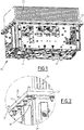
- the electronic equipment 10 comprises a structure 12, an electronic card 14, an assembly 16 of electronic components 18, a cooling module 20, and a thermally insulating flange 22.
- the structure 12 forms an enclosure.
- the structure 12 comprises four lateral walls 24 and a cover, not shown to show the interior of the structure 12.
- Each side wall 24 extends, in a direction substantially orthogonal to the electronic card 14, between a proximal edge and a distal edge. Each side wall 24 is connected to two adjacent sidewalls.
- Each side wall 24 has an inner face 26 facing the interior of the structure 12 and an outer face 28 facing outwardly of the structure 12.
- each side wall 24 comprises a lateral flank 30 substantially orthogonal to the electronic card 14 and a support flange 32 substantially orthogonal to the lateral flank 30, forming the proximal edge of the side wall 24.
- the cover 33 extends in a longitudinal plane, substantially orthogonal to the side walls 24.
- the cover 33 bears on the distal edges of at least a portion of the side walls 24.
- the hood 33 is supported on the distal edges of the four side walls 24.
- the structure 12 thus forms an enclosure delimited by the side walls 24 and the cover 33.
- This enclosure is open, i.e. does not have a second longitudinal cover which would be connected to the proximal edges of the side walls.
- the electronic card 14 and the electronic components 18 are received in this enclosure.
- the electronic components 18 are connected to the electronic card 14.
- the electronic components 18 are disposed inside the structure 12, in particular inside the enclosure delimited by the structure 12.
- the electronic components include, for example, transistors.
- the set of electronic components 16 comprises at least one switching module 34, each switching module 34 being formed of two switches connected in series.
- Each switch comprises for example a bipolar transistor insulated gate, also called IGBT (English Insulated Gate Bipolar Transistor ) .
- each switch comprises a bipolar transistor, or a JFET ( Junction Field Effect Transistor ) type transistor , or a thyristor, such as a trigger-off thyristor, or GTO (from the English language).
- Gate Turn-Off Thyristor .
- the electrical components 18 are in direct contact with the cooling module 20. In one configuration, the electrical components 18 are attached to the cooling module 20.
- the cooling module 20 is disposed on the proximal side of the side walls 24, as shown in FIG. figure 1 .
- the cooling module forms a second longitudinal hood closing the enclosure formed by the structure 12.
- the cooling module 20 is disposed outside of the structure 12.
- the cooling module 20 is configured to cool the assembly 16 of the electronic components 18, evacuating outwardly of the structure 12 at least a portion of the heat dissipated by the electronic components 18, in operation.
- the cooling module 20 is also able to cool the electronic card 14.
- the cooling module 20 comprises for example a finned radiator, a flow of air then being intended to circulate between the fins of the radiator to evacuate the heat dissipated by the electronic components 18 during their operation.
- the cooling module 20 comprises a Peltier module or a heat pipe.
- the flange 22 is interposed between the cooling module 20 and at least one side wall 24 of the structure 12, the flange 22 being in contact with the cooling module 20 and with the proximal edge of at least one wall 24.
- the flange 22 is interposed between the cooling module 20 and each of the four lateral walls 24, the flange 22 being in contact with the cooling module 20 and with each of the four lateral walls 24.
- the flange 22 is interposed between the cooling module 20 and the support flange 32 of each side wall 24, the flange 22 being in contact with the cooling module 20 and the support flange 32.
- the flange 22 is preferably fixed to the support flange 32 of at least one of the side walls 24, or preferably fixed by at least one captive screw 36.
- the flange 22 is made of a thermally insulating material, for example made of Muscotherm®. Thus, the flange 22 is able to prevent the formation of a thermal bridge between the cooling module 20, via the flange 22, and the structure 12.
- the heat transfer between the cooling module 20 and the structure 12, and the increase of the temperature inside the structure 12 due to this transfer is substantially reduced.
- part of the heat that passes between the cooling module 20 and the structure 12 is discharged to the outside via the cooling module 20, instead of being returned to the structure 12 via the contact between the structure 12 and the cooling module 20.
- heat transfer from the cooling module 20 to the structure 12 and radiation of this heat to the electronic components 18 contained in the structure 12 are avoided.
Landscapes
- Engineering & Computer Science (AREA)
- Microelectronics & Electronic Packaging (AREA)
- Physics & Mathematics (AREA)
- Thermal Sciences (AREA)
- Cooling Or The Like Of Electrical Apparatus (AREA)
- Cooling Or The Like Of Semiconductors Or Solid State Devices (AREA)
Applications Claiming Priority (1)
| Application Number | Priority Date | Filing Date | Title |
|---|---|---|---|
| FR1757758A FR3070219B1 (fr) | 2017-08-18 | 2017-08-18 | Equipement electronique d'un vehicule ferroviaire |
Publications (2)
| Publication Number | Publication Date |
|---|---|
| EP3445142A1 true EP3445142A1 (de) | 2019-02-20 |
| EP3445142B1 EP3445142B1 (de) | 2019-12-11 |
Family
ID=60955130
Family Applications (1)
| Application Number | Title | Priority Date | Filing Date |
|---|---|---|---|
| EP18187991.7A Active EP3445142B1 (de) | 2017-08-18 | 2018-08-08 | Elektronische ausstattung eines schienenfahrzeugs |
Country Status (2)
| Country | Link |
|---|---|
| EP (1) | EP3445142B1 (de) |
| FR (1) | FR3070219B1 (de) |
Cited By (1)
| Publication number | Priority date | Publication date | Assignee | Title |
|---|---|---|---|---|
| FR3100422A1 (fr) * | 2019-09-04 | 2021-03-05 | Alstom Transport Technologies | Dispositif à cartes électroniques avec dissipateur thermique |
Citations (6)
| Publication number | Priority date | Publication date | Assignee | Title |
|---|---|---|---|---|
| JPH11251499A (ja) * | 1998-03-06 | 1999-09-17 | Hitachi Ltd | 電力変換装置 |
| EP1259104A1 (de) * | 2001-05-18 | 2002-11-20 | Alstom | Leistungswandlersystem eines Schienenfahrzeuges |
| FR2875374A1 (fr) * | 2004-08-31 | 2006-03-17 | Mitsubishi Electric Corp | Convertisseur de puissance de vehicule |
| US20130016481A1 (en) * | 2011-07-13 | 2013-01-17 | Fuji Electric Co., Ltd. | Electric power converter for rolling stock |
| US20150371920A1 (en) * | 2013-03-26 | 2015-12-24 | Mitsubishi Electric Corporation | Vehicular power conversion device |
| US20160352242A1 (en) * | 2014-02-07 | 2016-12-01 | Mitsubishi Electric Corporation | Power conversion apparatus |
-
2017
- 2017-08-18 FR FR1757758A patent/FR3070219B1/fr not_active Expired - Fee Related
-
2018
- 2018-08-08 EP EP18187991.7A patent/EP3445142B1/de active Active
Patent Citations (6)
| Publication number | Priority date | Publication date | Assignee | Title |
|---|---|---|---|---|
| JPH11251499A (ja) * | 1998-03-06 | 1999-09-17 | Hitachi Ltd | 電力変換装置 |
| EP1259104A1 (de) * | 2001-05-18 | 2002-11-20 | Alstom | Leistungswandlersystem eines Schienenfahrzeuges |
| FR2875374A1 (fr) * | 2004-08-31 | 2006-03-17 | Mitsubishi Electric Corp | Convertisseur de puissance de vehicule |
| US20130016481A1 (en) * | 2011-07-13 | 2013-01-17 | Fuji Electric Co., Ltd. | Electric power converter for rolling stock |
| US20150371920A1 (en) * | 2013-03-26 | 2015-12-24 | Mitsubishi Electric Corporation | Vehicular power conversion device |
| US20160352242A1 (en) * | 2014-02-07 | 2016-12-01 | Mitsubishi Electric Corporation | Power conversion apparatus |
Cited By (1)
| Publication number | Priority date | Publication date | Assignee | Title |
|---|---|---|---|---|
| FR3100422A1 (fr) * | 2019-09-04 | 2021-03-05 | Alstom Transport Technologies | Dispositif à cartes électroniques avec dissipateur thermique |
Also Published As
| Publication number | Publication date |
|---|---|
| EP3445142B1 (de) | 2019-12-11 |
| FR3070219B1 (fr) | 2019-09-06 |
| FR3070219A1 (fr) | 2019-02-22 |
Similar Documents
| Publication | Publication Date | Title |
|---|---|---|
| EP3098949A1 (de) | Stator, der einen integrierten kühler umfasst | |
| FR3024770A1 (fr) | Plaque d'echange thermique pour gestion thermique de pack batteries | |
| FR3054095A1 (fr) | Dispositif de refroidissement d'un circuit electronique de puissance | |
| EP3445142B1 (de) | Elektronische ausstattung eines schienenfahrzeugs | |
| EP3367770A1 (de) | Leistungsmodul mit kühlsystem der elektronischen karten | |
| EP3749537B1 (de) | Gebläsesteuermodul und entsprechende heizungs- und/oder belüftungs- und/oder klimaanlage | |
| US20200077543A1 (en) | High performance outdoor edge server | |
| EP2936954B1 (de) | Belüftungsvorrichtung für eine lüftungs-, heizungs- und/oder klimaanlage | |
| EP1439971B1 (de) | Motor-gebläse, inbesondere für eine heizungs- und/oder klimaanlage eines fahrzeuges | |
| WO2014095610A1 (fr) | Dispositif de refroidissement pour carte de circuit imprime | |
| JP2004254387A (ja) | 電力変換装置 | |
| FR3070231B1 (fr) | Equipement electronique comprenant une bride de fixation | |
| FR3091510A1 (fr) | Système d’échange thermique, ensemble d’échange thermique comprenant un tel système, véhicule ferroviaire et procédé associés | |
| EP1388444A1 (de) | Klimaanlage | |
| FR3098081A1 (fr) | Circuit de refroidissement pour logement électronique avec module de puissance | |
| FR3056374B1 (fr) | Convertisseur d'energie electrique avec ecran thermique entre deux ensembles de composant(s) electrique(s) | |
| WO2019120915A1 (fr) | Electronique de puissance refroidie par un flux | |
| JP7001089B2 (ja) | 蓄電装置 | |
| FR3103887A1 (fr) | Dispositif de chauffage électrique d’un liquide caloporteur pour véhicule automobile | |
| EP4391756A1 (de) | Leistungselektronikvorrichtung | |
| FR3156512A1 (fr) | Pompe à chaleur pour un chauffage d’immeuble et chauffage ainsi équipé | |
| WO2023046736A1 (fr) | Ensemble électronique comportant un élément de refroidissement amélioré | |
| FR3158696A1 (fr) | Capot avant de véhicule automobile configuré pour refroidir un échangeur de chaleur | |
| KR0138746Y1 (ko) | 차량용 냉/온장고의 수냉식 방열구조 | |
| FR2846142A1 (fr) | Dispositif de refroidissement de sectionneur sous gaine |
Legal Events
| Date | Code | Title | Description |
|---|---|---|---|
| PUAI | Public reference made under article 153(3) epc to a published international application that has entered the european phase |
Free format text: ORIGINAL CODE: 0009012 |
|
| STAA | Information on the status of an ep patent application or granted ep patent |
Free format text: STATUS: THE APPLICATION HAS BEEN PUBLISHED |
|
| AK | Designated contracting states |
Kind code of ref document: A1 Designated state(s): AL AT BE BG CH CY CZ DE DK EE ES FI FR GB GR HR HU IE IS IT LI LT LU LV MC MK MT NL NO PL PT RO RS SE SI SK SM TR |
|
| AX | Request for extension of the european patent |
Extension state: BA ME |
|
| STAA | Information on the status of an ep patent application or granted ep patent |
Free format text: STATUS: REQUEST FOR EXAMINATION WAS MADE |
|
| 17P | Request for examination filed |
Effective date: 20190220 |
|
| RBV | Designated contracting states (corrected) |
Designated state(s): AL AT BE BG CH CY CZ DE DK EE ES FI FR GB GR HR HU IE IS IT LI LT LU LV MC MK MT NL NO PL PT RO RS SE SI SK SM TR |
|
| GRAP | Despatch of communication of intention to grant a patent |
Free format text: ORIGINAL CODE: EPIDOSNIGR1 |
|
| STAA | Information on the status of an ep patent application or granted ep patent |
Free format text: STATUS: GRANT OF PATENT IS INTENDED |
|
| INTG | Intention to grant announced |
Effective date: 20190715 |
|
| GRAS | Grant fee paid |
Free format text: ORIGINAL CODE: EPIDOSNIGR3 |
|
| GRAA | (expected) grant |
Free format text: ORIGINAL CODE: 0009210 |
|
| STAA | Information on the status of an ep patent application or granted ep patent |
Free format text: STATUS: THE PATENT HAS BEEN GRANTED |
|
| AK | Designated contracting states |
Kind code of ref document: B1 Designated state(s): AL AT BE BG CH CY CZ DE DK EE ES FI FR GB GR HR HU IE IS IT LI LT LU LV MC MK MT NL NO PL PT RO RS SE SI SK SM TR |
|
| REG | Reference to a national code |
Ref country code: GB Ref legal event code: FG4D Free format text: NOT ENGLISH |
|
| REG | Reference to a national code |
Ref country code: CH Ref legal event code: EP |
|
| REG | Reference to a national code |
Ref country code: AT Ref legal event code: REF Ref document number: 1213526 Country of ref document: AT Kind code of ref document: T Effective date: 20191215 |
|
| REG | Reference to a national code |
Ref country code: DE Ref legal event code: R096 Ref document number: 602018001574 Country of ref document: DE |
|
| REG | Reference to a national code |
Ref country code: IE Ref legal event code: FG4D Free format text: LANGUAGE OF EP DOCUMENT: FRENCH |
|
| REG | Reference to a national code |
Ref country code: NL Ref legal event code: MP Effective date: 20191211 |
|
| REG | Reference to a national code |
Ref country code: LT Ref legal event code: MG4D |
|
| PG25 | Lapsed in a contracting state [announced via postgrant information from national office to epo] |
Ref country code: GR Free format text: LAPSE BECAUSE OF FAILURE TO SUBMIT A TRANSLATION OF THE DESCRIPTION OR TO PAY THE FEE WITHIN THE PRESCRIBED TIME-LIMIT Effective date: 20200312 Ref country code: NO Free format text: LAPSE BECAUSE OF FAILURE TO SUBMIT A TRANSLATION OF THE DESCRIPTION OR TO PAY THE FEE WITHIN THE PRESCRIBED TIME-LIMIT Effective date: 20200311 Ref country code: LT Free format text: LAPSE BECAUSE OF FAILURE TO SUBMIT A TRANSLATION OF THE DESCRIPTION OR TO PAY THE FEE WITHIN THE PRESCRIBED TIME-LIMIT Effective date: 20191211 Ref country code: FI Free format text: LAPSE BECAUSE OF FAILURE TO SUBMIT A TRANSLATION OF THE DESCRIPTION OR TO PAY THE FEE WITHIN THE PRESCRIBED TIME-LIMIT Effective date: 20191211 Ref country code: BG Free format text: LAPSE BECAUSE OF FAILURE TO SUBMIT A TRANSLATION OF THE DESCRIPTION OR TO PAY THE FEE WITHIN THE PRESCRIBED TIME-LIMIT Effective date: 20200311 Ref country code: LV Free format text: LAPSE BECAUSE OF FAILURE TO SUBMIT A TRANSLATION OF THE DESCRIPTION OR TO PAY THE FEE WITHIN THE PRESCRIBED TIME-LIMIT Effective date: 20191211 Ref country code: SE Free format text: LAPSE BECAUSE OF FAILURE TO SUBMIT A TRANSLATION OF THE DESCRIPTION OR TO PAY THE FEE WITHIN THE PRESCRIBED TIME-LIMIT Effective date: 20191211 |
|
| PG25 | Lapsed in a contracting state [announced via postgrant information from national office to epo] |
Ref country code: HR Free format text: LAPSE BECAUSE OF FAILURE TO SUBMIT A TRANSLATION OF THE DESCRIPTION OR TO PAY THE FEE WITHIN THE PRESCRIBED TIME-LIMIT Effective date: 20191211 Ref country code: RS Free format text: LAPSE BECAUSE OF FAILURE TO SUBMIT A TRANSLATION OF THE DESCRIPTION OR TO PAY THE FEE WITHIN THE PRESCRIBED TIME-LIMIT Effective date: 20191211 |
|
| PG25 | Lapsed in a contracting state [announced via postgrant information from national office to epo] |
Ref country code: AL Free format text: LAPSE BECAUSE OF FAILURE TO SUBMIT A TRANSLATION OF THE DESCRIPTION OR TO PAY THE FEE WITHIN THE PRESCRIBED TIME-LIMIT Effective date: 20191211 |
|
| PG25 | Lapsed in a contracting state [announced via postgrant information from national office to epo] |
Ref country code: CZ Free format text: LAPSE BECAUSE OF FAILURE TO SUBMIT A TRANSLATION OF THE DESCRIPTION OR TO PAY THE FEE WITHIN THE PRESCRIBED TIME-LIMIT Effective date: 20191211 Ref country code: EE Free format text: LAPSE BECAUSE OF FAILURE TO SUBMIT A TRANSLATION OF THE DESCRIPTION OR TO PAY THE FEE WITHIN THE PRESCRIBED TIME-LIMIT Effective date: 20191211 Ref country code: PT Free format text: LAPSE BECAUSE OF FAILURE TO SUBMIT A TRANSLATION OF THE DESCRIPTION OR TO PAY THE FEE WITHIN THE PRESCRIBED TIME-LIMIT Effective date: 20200506 Ref country code: ES Free format text: LAPSE BECAUSE OF FAILURE TO SUBMIT A TRANSLATION OF THE DESCRIPTION OR TO PAY THE FEE WITHIN THE PRESCRIBED TIME-LIMIT Effective date: 20191211 Ref country code: NL Free format text: LAPSE BECAUSE OF FAILURE TO SUBMIT A TRANSLATION OF THE DESCRIPTION OR TO PAY THE FEE WITHIN THE PRESCRIBED TIME-LIMIT Effective date: 20191211 Ref country code: RO Free format text: LAPSE BECAUSE OF FAILURE TO SUBMIT A TRANSLATION OF THE DESCRIPTION OR TO PAY THE FEE WITHIN THE PRESCRIBED TIME-LIMIT Effective date: 20191211 |
|
| PG25 | Lapsed in a contracting state [announced via postgrant information from national office to epo] |
Ref country code: IS Free format text: LAPSE BECAUSE OF FAILURE TO SUBMIT A TRANSLATION OF THE DESCRIPTION OR TO PAY THE FEE WITHIN THE PRESCRIBED TIME-LIMIT Effective date: 20200411 Ref country code: SK Free format text: LAPSE BECAUSE OF FAILURE TO SUBMIT A TRANSLATION OF THE DESCRIPTION OR TO PAY THE FEE WITHIN THE PRESCRIBED TIME-LIMIT Effective date: 20191211 Ref country code: SM Free format text: LAPSE BECAUSE OF FAILURE TO SUBMIT A TRANSLATION OF THE DESCRIPTION OR TO PAY THE FEE WITHIN THE PRESCRIBED TIME-LIMIT Effective date: 20191211 |
|
| REG | Reference to a national code |
Ref country code: DE Ref legal event code: R097 Ref document number: 602018001574 Country of ref document: DE |
|
| REG | Reference to a national code |
Ref country code: AT Ref legal event code: MK05 Ref document number: 1213526 Country of ref document: AT Kind code of ref document: T Effective date: 20191211 |
|
| PLBE | No opposition filed within time limit |
Free format text: ORIGINAL CODE: 0009261 |
|
| STAA | Information on the status of an ep patent application or granted ep patent |
Free format text: STATUS: NO OPPOSITION FILED WITHIN TIME LIMIT |
|
| PG25 | Lapsed in a contracting state [announced via postgrant information from national office to epo] |
Ref country code: DK Free format text: LAPSE BECAUSE OF FAILURE TO SUBMIT A TRANSLATION OF THE DESCRIPTION OR TO PAY THE FEE WITHIN THE PRESCRIBED TIME-LIMIT Effective date: 20191211 |
|
| 26N | No opposition filed |
Effective date: 20200914 |
|
| PG25 | Lapsed in a contracting state [announced via postgrant information from national office to epo] |
Ref country code: SI Free format text: LAPSE BECAUSE OF FAILURE TO SUBMIT A TRANSLATION OF THE DESCRIPTION OR TO PAY THE FEE WITHIN THE PRESCRIBED TIME-LIMIT Effective date: 20191211 Ref country code: AT Free format text: LAPSE BECAUSE OF FAILURE TO SUBMIT A TRANSLATION OF THE DESCRIPTION OR TO PAY THE FEE WITHIN THE PRESCRIBED TIME-LIMIT Effective date: 20191211 |
|
| PG25 | Lapsed in a contracting state [announced via postgrant information from national office to epo] |
Ref country code: IT Free format text: LAPSE BECAUSE OF FAILURE TO SUBMIT A TRANSLATION OF THE DESCRIPTION OR TO PAY THE FEE WITHIN THE PRESCRIBED TIME-LIMIT Effective date: 20191211 |
|
| PG25 | Lapsed in a contracting state [announced via postgrant information from national office to epo] |
Ref country code: PL Free format text: LAPSE BECAUSE OF FAILURE TO SUBMIT A TRANSLATION OF THE DESCRIPTION OR TO PAY THE FEE WITHIN THE PRESCRIBED TIME-LIMIT Effective date: 20191211 |
|
| PG25 | Lapsed in a contracting state [announced via postgrant information from national office to epo] |
Ref country code: MC Free format text: LAPSE BECAUSE OF FAILURE TO SUBMIT A TRANSLATION OF THE DESCRIPTION OR TO PAY THE FEE WITHIN THE PRESCRIBED TIME-LIMIT Effective date: 20191211 |
|
| PG25 | Lapsed in a contracting state [announced via postgrant information from national office to epo] |
Ref country code: LU Free format text: LAPSE BECAUSE OF NON-PAYMENT OF DUE FEES Effective date: 20200808 |
|
| REG | Reference to a national code |
Ref country code: BE Ref legal event code: MM Effective date: 20200831 |
|
| PG25 | Lapsed in a contracting state [announced via postgrant information from national office to epo] |
Ref country code: IE Free format text: LAPSE BECAUSE OF NON-PAYMENT OF DUE FEES Effective date: 20200808 Ref country code: BE Free format text: LAPSE BECAUSE OF NON-PAYMENT OF DUE FEES Effective date: 20200831 |
|
| REG | Reference to a national code |
Ref country code: CH Ref legal event code: PL |
|
| PG25 | Lapsed in a contracting state [announced via postgrant information from national office to epo] |
Ref country code: LI Free format text: LAPSE BECAUSE OF NON-PAYMENT OF DUE FEES Effective date: 20210831 Ref country code: CH Free format text: LAPSE BECAUSE OF NON-PAYMENT OF DUE FEES Effective date: 20210831 |
|
| PG25 | Lapsed in a contracting state [announced via postgrant information from national office to epo] |
Ref country code: TR Free format text: LAPSE BECAUSE OF FAILURE TO SUBMIT A TRANSLATION OF THE DESCRIPTION OR TO PAY THE FEE WITHIN THE PRESCRIBED TIME-LIMIT Effective date: 20191211 Ref country code: MT Free format text: LAPSE BECAUSE OF FAILURE TO SUBMIT A TRANSLATION OF THE DESCRIPTION OR TO PAY THE FEE WITHIN THE PRESCRIBED TIME-LIMIT Effective date: 20191211 Ref country code: CY Free format text: LAPSE BECAUSE OF FAILURE TO SUBMIT A TRANSLATION OF THE DESCRIPTION OR TO PAY THE FEE WITHIN THE PRESCRIBED TIME-LIMIT Effective date: 20191211 |
|
| PG25 | Lapsed in a contracting state [announced via postgrant information from national office to epo] |
Ref country code: MK Free format text: LAPSE BECAUSE OF FAILURE TO SUBMIT A TRANSLATION OF THE DESCRIPTION OR TO PAY THE FEE WITHIN THE PRESCRIBED TIME-LIMIT Effective date: 20191211 |
|
| P01 | Opt-out of the competence of the unified patent court (upc) registered |
Effective date: 20230823 |
|
| REG | Reference to a national code |
Ref country code: GB Ref legal event code: 732E Free format text: REGISTERED BETWEEN 20250213 AND 20250219 |
|
| PGFP | Annual fee paid to national office [announced via postgrant information from national office to epo] |
Ref country code: DE Payment date: 20250820 Year of fee payment: 8 |
|
| PGFP | Annual fee paid to national office [announced via postgrant information from national office to epo] |
Ref country code: GB Payment date: 20250821 Year of fee payment: 8 |
|
| PGFP | Annual fee paid to national office [announced via postgrant information from national office to epo] |
Ref country code: FR Payment date: 20250828 Year of fee payment: 8 |