EP3445013A1 - Method and apparatus for providing next generation network service in heterogeneous network environment - Google Patents
Method and apparatus for providing next generation network service in heterogeneous network environment Download PDFInfo
- Publication number
- EP3445013A1 EP3445013A1 EP17796314.7A EP17796314A EP3445013A1 EP 3445013 A1 EP3445013 A1 EP 3445013A1 EP 17796314 A EP17796314 A EP 17796314A EP 3445013 A1 EP3445013 A1 EP 3445013A1
- Authority
- EP
- European Patent Office
- Prior art keywords
- network
- terminal
- base station
- transfer rate
- data transfer
- Prior art date
- Legal status (The legal status is an assumption and is not a legal conclusion. Google has not performed a legal analysis and makes no representation as to the accuracy of the status listed.)
- Granted
Links
- 238000000034 method Methods 0.000 title claims abstract description 85
- 238000004891 communication Methods 0.000 claims abstract description 36
- 238000012546 transfer Methods 0.000 claims description 104
- 238000010295 mobile communication Methods 0.000 claims description 36
- 230000005540 biological transmission Effects 0.000 claims description 31
- 238000009434 installation Methods 0.000 claims description 8
- 238000013500 data storage Methods 0.000 claims description 5
- HRULVFRXEOZUMJ-UHFFFAOYSA-K potassium;disodium;2-(4-chloro-2-methylphenoxy)propanoate;methyl-dioxido-oxo-$l^{5}-arsane Chemical compound [Na+].[Na+].[K+].C[As]([O-])([O-])=O.[O-]C(=O)C(C)OC1=CC=C(Cl)C=C1C HRULVFRXEOZUMJ-UHFFFAOYSA-K 0.000 claims description 2
- 230000008569 process Effects 0.000 abstract description 15
- 238000007726 management method Methods 0.000 description 19
- 238000010586 diagram Methods 0.000 description 12
- 238000005516 engineering process Methods 0.000 description 11
- 230000009977 dual effect Effects 0.000 description 7
- 230000004044 response Effects 0.000 description 6
- 238000007792 addition Methods 0.000 description 3
- 230000001413 cellular effect Effects 0.000 description 3
- 239000000126 substance Substances 0.000 description 3
- 230000008859 change Effects 0.000 description 2
- 238000012790 confirmation Methods 0.000 description 2
- 230000002779 inactivation Effects 0.000 description 2
- 238000012986 modification Methods 0.000 description 2
- 230000004048 modification Effects 0.000 description 2
- 238000012545 processing Methods 0.000 description 2
- 230000011664 signaling Effects 0.000 description 2
- 238000006467 substitution reaction Methods 0.000 description 2
- 230000004913 activation Effects 0.000 description 1
- 230000006835 compression Effects 0.000 description 1
- 238000007906 compression Methods 0.000 description 1
- 230000000694 effects Effects 0.000 description 1
- 238000005538 encapsulation Methods 0.000 description 1
- 230000007774 longterm Effects 0.000 description 1
- 238000005259 measurement Methods 0.000 description 1
- 230000011218 segmentation Effects 0.000 description 1
Images


Classifications
-
- H—ELECTRICITY
- H04—ELECTRIC COMMUNICATION TECHNIQUE
- H04L—TRANSMISSION OF DIGITAL INFORMATION, e.g. TELEGRAPHIC COMMUNICATION
- H04L67/00—Network arrangements or protocols for supporting network services or applications
- H04L67/14—Session management
- H04L67/141—Setup of application sessions
-
- H—ELECTRICITY
- H04—ELECTRIC COMMUNICATION TECHNIQUE
- H04L—TRANSMISSION OF DIGITAL INFORMATION, e.g. TELEGRAPHIC COMMUNICATION
- H04L1/00—Arrangements for detecting or preventing errors in the information received
- H04L1/12—Arrangements for detecting or preventing errors in the information received by using return channel
- H04L1/16—Arrangements for detecting or preventing errors in the information received by using return channel in which the return channel carries supervisory signals, e.g. repetition request signals
- H04L1/18—Automatic repetition systems, e.g. Van Duuren systems
-
- H—ELECTRICITY
- H04—ELECTRIC COMMUNICATION TECHNIQUE
- H04L—TRANSMISSION OF DIGITAL INFORMATION, e.g. TELEGRAPHIC COMMUNICATION
- H04L12/00—Data switching networks
- H04L12/54—Store-and-forward switching systems
- H04L12/56—Packet switching systems
- H04L12/5691—Access to open networks; Ingress point selection, e.g. ISP selection
-
- H—ELECTRICITY
- H04—ELECTRIC COMMUNICATION TECHNIQUE
- H04L—TRANSMISSION OF DIGITAL INFORMATION, e.g. TELEGRAPHIC COMMUNICATION
- H04L47/00—Traffic control in data switching networks
- H04L47/10—Flow control; Congestion control
- H04L47/22—Traffic shaping
- H04L47/225—Determination of shaping rate, e.g. using a moving window
-
- H—ELECTRICITY
- H04—ELECTRIC COMMUNICATION TECHNIQUE
- H04L—TRANSMISSION OF DIGITAL INFORMATION, e.g. TELEGRAPHIC COMMUNICATION
- H04L63/00—Network architectures or network communication protocols for network security
- H04L63/10—Network architectures or network communication protocols for network security for controlling access to devices or network resources
- H04L63/107—Network architectures or network communication protocols for network security for controlling access to devices or network resources wherein the security policies are location-dependent, e.g. entities privileges depend on current location or allowing specific operations only from locally connected terminals
-
- H—ELECTRICITY
- H04—ELECTRIC COMMUNICATION TECHNIQUE
- H04L—TRANSMISSION OF DIGITAL INFORMATION, e.g. TELEGRAPHIC COMMUNICATION
- H04L65/00—Network arrangements, protocols or services for supporting real-time applications in data packet communication
- H04L65/40—Support for services or applications
-
- H—ELECTRICITY
- H04—ELECTRIC COMMUNICATION TECHNIQUE
- H04L—TRANSMISSION OF DIGITAL INFORMATION, e.g. TELEGRAPHIC COMMUNICATION
- H04L69/00—Network arrangements, protocols or services independent of the application payload and not provided for in the other groups of this subclass
- H04L69/08—Protocols for interworking; Protocol conversion
- H04L69/085—Protocols for interworking; Protocol conversion specially adapted for interworking of IP-based networks with other networks
-
- H—ELECTRICITY
- H04—ELECTRIC COMMUNICATION TECHNIQUE
- H04L—TRANSMISSION OF DIGITAL INFORMATION, e.g. TELEGRAPHIC COMMUNICATION
- H04L9/00—Cryptographic mechanisms or cryptographic arrangements for secret or secure communications; Network security protocols
- H04L9/40—Network security protocols
-
- H—ELECTRICITY
- H04—ELECTRIC COMMUNICATION TECHNIQUE
- H04W—WIRELESS COMMUNICATION NETWORKS
- H04W12/00—Security arrangements; Authentication; Protecting privacy or anonymity
- H04W12/60—Context-dependent security
- H04W12/63—Location-dependent; Proximity-dependent
- H04W12/64—Location-dependent; Proximity-dependent using geofenced areas
-
- H—ELECTRICITY
- H04—ELECTRIC COMMUNICATION TECHNIQUE
- H04W—WIRELESS COMMUNICATION NETWORKS
- H04W28/00—Network traffic management; Network resource management
- H04W28/02—Traffic management, e.g. flow control or congestion control
- H04W28/0252—Traffic management, e.g. flow control or congestion control per individual bearer or channel
- H04W28/0257—Traffic management, e.g. flow control or congestion control per individual bearer or channel the individual bearer or channel having a maximum bit rate or a bit rate guarantee
-
- H—ELECTRICITY
- H04—ELECTRIC COMMUNICATION TECHNIQUE
- H04W—WIRELESS COMMUNICATION NETWORKS
- H04W48/00—Access restriction; Network selection; Access point selection
- H04W48/20—Selecting an access point
-
- H—ELECTRICITY
- H04—ELECTRIC COMMUNICATION TECHNIQUE
- H04W—WIRELESS COMMUNICATION NETWORKS
- H04W76/00—Connection management
- H04W76/10—Connection setup
-
- H—ELECTRICITY
- H04—ELECTRIC COMMUNICATION TECHNIQUE
- H04W—WIRELESS COMMUNICATION NETWORKS
- H04W76/00—Connection management
- H04W76/10—Connection setup
- H04W76/15—Setup of multiple wireless link connections
- H04W76/16—Involving different core network technologies, e.g. a packet-switched [PS] bearer in combination with a circuit-switched [CS] bearer
-
- H—ELECTRICITY
- H04—ELECTRIC COMMUNICATION TECHNIQUE
- H04W—WIRELESS COMMUNICATION NETWORKS
- H04W8/00—Network data management
- H04W8/22—Processing or transfer of terminal data, e.g. status or physical capabilities
- H04W8/24—Transfer of terminal data
-
- H—ELECTRICITY
- H04—ELECTRIC COMMUNICATION TECHNIQUE
- H04W—WIRELESS COMMUNICATION NETWORKS
- H04W88/00—Devices specially adapted for wireless communication networks, e.g. terminals, base stations or access point devices
- H04W88/08—Access point devices
- H04W88/10—Access point devices adapted for operation in multiple networks, e.g. multi-mode access points
-
- H—ELECTRICITY
- H04—ELECTRIC COMMUNICATION TECHNIQUE
- H04W—WIRELESS COMMUNICATION NETWORKS
- H04W92/00—Interfaces specially adapted for wireless communication networks
- H04W92/02—Inter-networking arrangements
Landscapes
- Engineering & Computer Science (AREA)
- Computer Networks & Wireless Communication (AREA)
- Signal Processing (AREA)
- Computer Security & Cryptography (AREA)
- Multimedia (AREA)
- Computer Hardware Design (AREA)
- Computing Systems (AREA)
- General Engineering & Computer Science (AREA)
- Databases & Information Systems (AREA)
- Mobile Radio Communication Systems (AREA)
- Management, Administration, Business Operations System, And Electronic Commerce (AREA)
Abstract
Description
- The present disclosure in some embodiments relates to a method and an apparatus for providing a next-generation network system in an interworking arrangement with an existing network system in a heterogeneous network environment.
- The statements in this section merely provide background information related to the present disclosure and do not necessarily constitute prior art.
-
FIG. 1 is a diagram of a protocol structure for supporting a dual connectivity technology employed by a conventional network. - A Packet Data Convergence Protocol (PDCP) layer supports efficient data transfer by using network protocols such as IPv4 or IPv6. In particular, for efficient transmission of IP packets, the PDCP layer uses a header compression method for compressing header information of packets.
- A Radio Link Control (RLC) layer, which is subordinate to the PDCP layer, constitutes an RLC Packet Data Unit (PDU) of a size suitable for radio transmission, and it performs an Automatic Repeat Request (ARQ) function that is responsible for retransmission of a lost RLC PDU during transmission. The transmit-side RLC layer constructs an RLC PDU suitable for transmission by using a segmentation and concatenation function of an RLC Service Data Unit (SDU) passed from the higher level. The receive-side RLC layer performs a data reassembly function to reconstruct the original RLC SDU. The RLC layer has an RLC buffer for storing RLC SDUs or RLC PDUs.
- A MAC layer transfers data received from the RLC layer to a terminal or a gateway.
-
FIG. 1 (a) is a protocol structure for supporting a dual connectivity technology by using a core network (CN) split method. - The structure of the protocol using the CN split method has relatively low complexity. Therefore, in the conventional network, such protocol structure can be introduced without major change compared to the earlier protocol structure prior to supporting the dual connectivity technology. The structure of the protocol using the CN splitting method is equivalent to a conventional protocol structure with only a specific bearer passed to another base station (Secondary eNodeB, SeNB).
- The master base station (Master eNodeB or MeNB) receives only an MCG bearer. The MCG bearer corresponds to a bearer which transfers data by using only the radio resources of the master base station. As with the master base station, the secondary base station (Secondary eNodeB or SeNB) receives only an SCG bearer. The SCG bearer, which has the same structure as the MCG bearer, is adapted to transfer data by using only the radio resources of the secondary base station.
-
FIG. 1(b) is a protocol structure for supporting a dual connectivity technology using the PDCP splitting method. - The dual connectivity technology using PDCP splitting method is a technology for separating bearers from the PDCP layer of one base station. Unlike the existing protocol structure, the structure of the protocol using the PDCP splitting method has two RLCs connected to one PDCP. This protocol structure allows one bearer to transfer data by using both the master base station and the secondary base station.
- The master base station receives split bearers along with MCG bearers. A split bearer is a bearer that transfers data by using radio resources of the master base station as well as the secondary base station.
- The existing network (LTE) has greatly improved the data transfer rate by using such dual connectivity technology. However, in the next-generation network, the maximum possible data transfer rate compared with the existing network is several tens of times higher, and this fact makes it difficult to provide the next-generation network simply with the system architectures that have served the existing networks.
- Therefore, there is a growing need for a new network structure in which an existing network and a next-generation network cooperate to provide an appropriate network according to the state of the terminal or the network.
- The present disclosure in some embodiments seeks to provide a method and apparatus which can reliably process high-speed data communication by using a next-generation network while operating in conjunction with an existing network.
- Further, the present disclosure in some embodiments aims to provide a method and an apparatus for selectively providing an existing network or a next-generation network to a terminal or a gateway in consideration of a state of the network or a state of the terminal.
- At least one aspect of the present disclosure provides a method performed by a base station control apparatus for controlling a base station of a mobile communication system including a plurality of heterogeneous networks of different generations. The method includes receiving, by the base station control apparatus, a network connection establishment message including information on utilization of a first network from a terminal, and deciding, by the base station control apparatus, whether to approve or disapprove utilization of the first network by the terminal by using previously stored information on the terminal and the information on utilization of the first network, and selecting, by the base station control apparatus, one between a gateway capable of providing a mobile communication service based on the first network to the terminal, and a gateway capable of providing a second network to the terminal, depending on whether utilization of the first network is determined to be approved or disapproved, and performing, by the base station control apparatus, a first transmission of a network connection establishment request to the gateway selected in the selecting.
- Another aspect of the present disclosure provides an apparatus for controlling a base station of a mobile communication system including a plurality of heterogeneous networks of different generations. The apparatus includes a communication unit, a data storage unit and a control unit. The communication unit is configured to receive from a terminal, a network connection establishment message including information on utilization of a first network, and to transmit a network connection establishment request to a selected gateway. The data storage unit is configured to store information on the terminal. The control unit is configured to decide whether to approve or disapprove utilization of the first network by the terminal by using the information on the terminal and the information on utilization of the first network, and to select one between a gateway capable of providing the first network to the terminal, and a gateway capable of providing a second network to the terminal, depending on whether utilization of the first network by the terminal is determined to be approved or disapproved.
- Yet another aspect of the present disclosure provides a method performed by a control plane gateway for determining a maximum data transfer rate in a mobile communication system including a plurality of heterogeneous networks of different generations. The method includes receiving, by the control plane gateway, information on a network connection establishment request including information on utilization of a first network by a terminal, from a base station control apparatus, and determining, by the control plane gateway, a maximum data transfer rate for the first network and a maximum data transfer rate for the second network to be provided to the terminal, by referring to the information on the utilization of the first network by the terminal, and performing a transmission by the control plane gateway. The performing of the transmission includes transmitting a flow table installation message to a user plane gateway so that traffic is transferred between the terminal and the user plane gateway, and transmitting to the base station control apparatus, a connection acceptance message including a determined maximum data transfer rate for the first network and a determined maximum data transfer rate for the second network.
- Yet another aspect of the present disclosure provides a method of operating a terminal by applying a maximum data transfer rate in a mobile communication system including a plurality of heterogeneous networks of different generations. The method includes receiving, by the terminal, a maximum data transfer rate for a first network, a maximum data transfer rate for a second network, and a packet, and performing, by the terminal, a first determination on whether or not the packet is a traffic that utilizes the first network, and performing, by the terminal, a second determination on whether or not the mobile communication system is activated utilizing the first network, and deciding, by the terminal, whether to control the traffic either by utilizing the first network by applying the maximum data transfer rate for the first network, or by utilizing the second network by applying the maximum data transfer rate for the second network, depending on results of the performing of the first determination and the performing of the second determination.
- Yet another aspect of the present disclosure provides a terminal apparatus for applying a maximum data transfer rate in a mobile communication system including a plurality of heterogeneous networks of different generations. The terminal apparatus includes a communication unit and a control unit. The communication unit is configured to receive a maximum data transfer rate for a first network, a maximum data transfer rate for a second network, and a packet. The control unit is configured to make decisions on whether or not the packet is a traffic that utilizes the first network and whether or not the mobile communication system is activated utilizing the first network, and to decide, depending on the results of the decisions, whether to control the traffic either by utilizing the first network by applying the maximum data transfer rate for the first network, or by utilizing the second network by applying the maximum data transfer rate for the second network.
- Yet another aspect of the present disclosure provides a method of operating a base station of a mobile communication system including a plurality of heterogeneous networks of different generations. The method includes receiving, by the base station, a network connection establishment message for a first network, including information on utilization of the first network from a terminal, and determining whether or not the base station supports interworking with the first network upon receiving the connection establishment message, and deciding whether to include the information on utilization of the first network in the connection establishment message depending on whether or not the base station supports interworking with the first network, and transmitting a conclusive connection establishment message after the deciding, to a base station control apparatus.
- Yet another aspect of the present disclosure provides a base station apparatus of a mobile communication system including a plurality of heterogeneous networks of different generations. The base station apparatus includes a communication unit and a control unit. The communication unit is configured to receive a connection establishment message for a first network, including information on utilization of the first network from a terminal, and to transmit a conclusive connection establishment message after deciding whether to incorporate the information on utilization of the first network, to a base station control apparatus. The control unit is configured to determine, when the communication unit receives the connection establishment message, whether the control unit supports interworking with the first network, and to decide whether to include the information on the utilization of the first network in the connection establishment message depending on whether the control unit supports the interworking with the first network.
- Yet another aspect of the present disclosure provides a method performed by a terminal for notifying whether a network is activated or deactivated in a mobile communication system including a plurality of networks of different generations, which are provided in an interworking arrangement respectively. The method includes determining, by the terminal, whether a first network that is in connection with the terminal is inactivated, and determining, by the terminal when the first network is inactivated, whether there is an uplink packet to be transmitted to a base station, and transmitting, by the terminal when there is an uplink packet to be transmitted to the base station, the uplink packet with a state of the first network being incorporated in a header of the uplink packet, to the base station, and generating, by the terminal when there is no uplink packet to be transmitted to the base station, a dummy packet for notifying the state of the first network, and transmitting the dummy packet to the base station.
- Yet another aspect of the present disclosure provides a method performed by a base station for notifying whether a network is activated or deactivated in a mobile communication system including a plurality of heterogeneous networks of different generations, which are provided in an interworking arrangement respectively. The method includes determining, by the base station, whether a first network that is in connection with the terminal is inactivated, and transmitting, by the base station, information on whether the first network is inactivated to a base station control apparatus.
- As described above, one aspect of the present disclosure can reliably process high-speed data communication by using a next-generation network while operating in conjunction with an existing network.
- Another aspect of the present disclosure can selectively provide an existing network or a next-generation network to a terminal or a gateway in consideration of a state of the network or a state of the terminal.
-
-
FIG. 1 is a diagram of a protocol structure for supporting a dual connectivity technology employed by a conventional network. -
FIG. 2 is a diagram of a system architecture in which an existing network and a next-generation network are interworking in accordance with at least one embodiment of the present disclosure. -
FIG. 3 is a flowchart of a process of providing a network to a terminal by a system architecture according to at least one embodiment of the present disclosure. -
FIG. 4A is a flowchart of a method that a terminal determines whether or not a base station supports interworking between an existing network and a next-generation network, according to at least one embodiment of the present disclosure. -
FIG. 4B is a flowchart of a method of determining whether or not a base station supports interworking between an existing network and a next-generation network, according to at least one embodiment of the present disclosure. -
FIG. 5A is a flowchart of a method of controlling a transfer rate by a terminal or a gateway according to a state of the terminal or a network, according to at least one embodiment of the present disclosure. -
FIG. 5B is a flowchart of a method of controlling a transfer rate by a terminal or a gateway according to a state of the terminal or a network, according to another embodiment of the present disclosure. -
FIG. 6 is a flowchart of a process that a system architecture according to at least one embodiment of the present disclosure determines whether or not the next-generation network is activated. -
FIG. 7 is a flowchart of a method that a terminal determines and notifies whether or not the next-generation network is activated, according to at least one embodiment of the present disclosure. -
FIG. 8 is a block diagram of a terminal according to at least one embodiment of the present disclosure. -
FIG. 9 is a block diagram of a base station according to at least one embodiment of the present disclosure. -
FIG. 10 is a block diagram of a base station control node according to at least one embodiment of the present disclosure. -
FIG. 11 is a block diagram of a gateway according to at least one embodiment of the present disclosure. -
FIG. 12 is flowcharts of processes performed by system architectures according to some embodiments of the present disclosure for transmission of information for utilizing a next-generation network over an existing network. - Hereinafter, some embodiments of the present disclosure will be described in detail with reference to the accompanying drawings. In the following description, like reference numerals designate like elements, although the elements are shown in different drawings. Further, in the following description of some embodiments, a detailed description of known functions and configurations incorporated therein will be omitted for the purpose of clarity and for brevity.
- Additionally, various terms such as first, second, A, B, (a), (b), etc., are used solely for the purpose of differentiating one component from the other, not to imply or suggest the substances, the order or sequence of the components. Throughout this specification, when a part "includes" or "comprises" a component, the part is meant to further include other components, not excluding thereof unless specifically stated to the contrary. The terms such as "unit," "module," and the like refer to units for processing at least one function or operation, which may be implemented by hardware, software, or a combination thereof.
- In order to explain embodiments of the present disclosure, connectivity or a communication service using a network provided for a user terminal can be easily replaced with the term network. In addition, the next-generation network may include all existing technologies including long term evolution (LTE) and evolved packet core (EPC), that is, technologies that appeared after the fourth generation network. For example, the next-generation network may include a fifth generation communication network or a network utilizing a new radio access technology (NR) for a fifth generation communication network.
-
FIG. 2 is a diagram of a system architecture in which an existing network and a next-generation network are interworking in accordance with at least one embodiment of the present disclosure. - Referring to
FIG. 2 , asystem architecture 200 according to some embodiments of the present disclosure includes a terminal 210, an existingnetwork base station 220, a next-generationnetwork base station 230, a basestation control node 240, acontrol plane gateway 250 and auser plane gateway 260. - The terminal 210 is a device that attempts to use a wireless network by connecting to a cellular network by using the existing
network base station 220 or the next-generationnetwork base station 230. The terminal 210 includes any smart devices that can use wireless networks such as smart phones, tablet PCs, smart watches, and includes others such as notebook computers, laptop computers, personal digital assistants (PDAs) and the like. - The
base stations base stations core network 270. - Serving as a component for performing the signaling and control functions, the base
station control node 240 manages terminal mobility such as access of the terminal 210 to the network, allocation of network resources, and the like. The basestation control node 240 performs the above-described functions on a control plane related to a subscriber and session management. More specifically, the basestation control node 240 serves to decide whether or not to provide the next-generation network to the terminal, and if yes, determine the kind of control plane gateway to provide the next-generation network to the terminal, and the like. The basestation control node 240 may be implemented as, but not limited to, a mobility management entity (MME), and it may be replaced by any objects capable of performing the above-described functions. - The base
station control node 240 connects the existingnetwork base station 220 and thecontrol plane gateway 250 on the control plane to exchange control messages with each other. In thissystem architecture 200 according to at least one embodiment of the present disclosure where the basestation control node 240 connects the existingnetwork base station 220 and thecontrol plane gateway 250 on the control plane, the control message is transmitted to and received from only the existingnetwork base station 220, and the control message is not transmitted to the next-generationnetwork base station 230. - The
control plane gateway 250 is a component that supports terminal mobility on the control plane and performs signaling and control functions. Thecontrol plane gateway 250 performs functions such as policy control, mobility management, or bearer management. Specifically, thecontrol plane gateway 250 makes a decision on whether to provide the next-generation network to the terminal 210, the maximum data transfer rate of the network to be determined, and the like. - The
control plane gateway 250 connects the basestation control node 240 and theuser plane gateway 260 on the control plane to exchange control messages with each other. - The
user plane gateway 260 transmits and receives data on the user plane. Theuser plane gateway 260 performs functions such as packet forwarding, proceeding tunnel encapsulation and decapsulation or Quality of Service (QoS) guarantee of user packets. - In the
system architecture 200 according to the embodiment of the present disclosure shown inFIG. 2 , the dotted lines show the user plane interface, the solid lines the control plane interface, the dash-dot-dotted lines the network connection between the terminal and the base station. - The terminal 210 is connected to the existing
network base station 220 or the next-generationnetwork base station 230, and it receives network service provided by one or both of the two base stations. - In the
system architecture 200 according to some embodiments of the present disclosure, only the existingnetwork base station 220 is connected to thecontrol plane gateway 250 using the control plane interface via the basestation control node 240. Thecontrol plane gateway 250 transmits its decisions to theuser plane gateway 260. - In the
system architecture 200 according to some embodiments of the present disclosure, the existingnetwork base station 220 or the next-generationnetwork base station 230 is linked with theuser plane gateway 260 by using the user plane interface. When the CN splitting method is employed for interworking between the existing network and the next-generation network, theuser plane gateway 260 is linked to the existingnetwork base station 220 and the next-generationnetwork base station 230 respectively by using the user plane interface. On the other hand, when the PDCP splitting method is employed for interworking between the existing network and the next-generation network, theuser plane gateway 260 is linked via the user plane interface with only the existingnetwork base station 220 which is linked with the next-generationnetwork base station 230 via the user plane interface. - Although the
system architecture 200 inFIG. 2 is shown assuming use of a gateway in which the user plane and the control plane are separated, it is not limited thereto. Thesystem architecture 200 according to some embodiments of the present disclosure utilizes a Serving Gateway (S-GW) and a Packet data network Gateway (P-GW) in which the user plane and the control plane are not separated from each other. - In addition, for example, the existing network is LTE, and the next-generation network may be a 5G mobile communication system, but it is not necessarily limited thereto. The existing network may refer to any networks complete with a system architecture for providing the mobile communication service, and the next-generation network may refer to a network with no complete system structure for providing mobile communication service, including 5G mobile communication system.
-
FIG. 3 is a flowchart of a process of providing a network to a terminal by a system architecture according to at least one embodiment of the present disclosure. - The terminal 210 transmits a network connection establishment message to the existing
network base station 220, and this message is transmitted to the base station control node 240 (S310). When first attempting to establish a connection to the network or when a connection is required to another network separately from the network to which the terminal is already connected, the terminal 210 transmits the network connection establishment message to the basestation control node 240. At this time, the terminal 210 may transmit the network connection establishment message with information included on the use of the next-generation network. The information on utilization of the next-generation network includes capability information indicating whether the terminal 210 is capable of supporting the next-generation network, or access point name (APN) information indicating that the terminal 210 desires to use the next-generation network, or the like. - Upon receiving the network connection establishment message, the base
station control node 240 makes a decision on whether or not to permit use of the next-generation network and on the maximum data transfer rate for each network, and it selects a gateway node capable of supporting the decisions made (S320). In deciding whether or not to approve utilization of the next-generation network, the basestation control node 240 utilizes information on the terminal previously stored in a subscriber information database or home subscriber server (HSS) or information on whether to activate the next-generation network to access the terminal, in addition to the information on utilization of the next-generation network included in the network connection establishment message. The information on the terminal includes information on whether or not the terminal 210 has been registered in a service that can use the next-generation network, information on whether or not the terminal 120 has exceeded the usage limit for the next-generation network, among others. The information on whether to activate the next-generation network to access the terminal includes information on whether to permit user plane connectivity using the next-generation network and the like. Upon receiving the information on the terminal previously stored in the subscriber information database or the information on whether to activate the next-generation network to access the terminal, the basestation control node 240 saves the same in the form of access restriction Information. The basestation control node 240 can decide whether or not to allow the terminal 210 to use the next-generation network by also receiving the terminal location information from the terminal 210 together with the aforementioned information. Based on the location information of the terminal, the basestation control node 240 additionally determines whether the terminal belongs to the service area of the next-generation network, so that the basestation control node 240 can decide whether or not to allow the terminal 210 to use the next-generation network. The basestation control node 240 can permit the terminal 210 to use the next-generation network, when the terminal 210 satisfies one or more combinations of the above conditions, that is, when the terminal 210 supports the next-generation network, the terminal 210 requests utilization of the next-generation network, the terminal 210 is subscribing to a service that can use the next-generation network, the terminal 210 has not exceeded the usage limit for the next-generation network, and the terminal 210 belongs to a service area of the next-generation network. The basestation control node 240 decides whether to approve or disapprove utilization of the next-generation network, and it can determine the maximum data transfer rate for each network at the same time. The basestation control node 240 can determine the maximum data transfer rate for each network, regardless of whether or not the terminal is permitted to use the next-generation network. Here, the maximum data transfer rate may be in the form of aggregated maximum bit rate (AMBR), or APN-AMBR applied to a specific access point name (APN). - The base
station control node 240 selects a gateway node that can support the network depending on whether or not to permit to use the next-generation network by the terminal. When permitting the use of the next-generation network by the terminal, the basestation control node 240 selects the gateway node to provide the next-generation network. In selecting a gateway node to provide a next-generation network, the basestation control node 240 can make the selection by additionally taking account of whether the gateway node is capable or incapable of supporting the maximum data transfer rate for the next-generation network or whether the gateway node is one where the user plane and the control plane are separated. The basestation control node 240 may support the maximum data transfer rate and preferentially select the gateway node where the user plane and the control plane are separated. Conversely, when disallowing the use of the next-generation network by the terminal, the basestation control node 240 selects a gateway node to provide the existing network. In selecting a gateway node to provide an existing network, the basestation control node 240 may preferentially select a gateway node capable of supporting the maximum data transfer rate for the existing network. - The base
station control node 240 transmits a network connection establishment request to the gateway node selected through the process described above (S330). The basestation control node 240 may transmit the network connection establishment request by incorporating information on the utilization of the next-generation network, the maximum data transfer rate for the next-generation network or the maximum data transfer rate for the existing network. In particular, when the terminal is permitted to use the next-generation network, the network connection establishment request transmitted by the basestation control node 240 to the gateway node, may include both of the maximum data transfer rate for the existing network and the maximum data transfer rate for the next-generation network. - The
control plane gateway 250 determines the maximum data transfer rate for the next-generation network and the maximum data transfer rate for the existing network, respectively, which will be applied to the connection between the terminal and the user plane gateway (S340). Thecontrol plane gateway 250 receives from the basestation control node 240, information on utilization of the next-generation network, information on the maximum data transfer rate for the existing network, and the maximum data transfer rate for the next-generation network. In addition, thecontrol plane gateway 250 receives information on the policy and charging on the terminal 210 from nodes of other base stations, for example, a policy and charging management system or the like. In determining the maximum data transfer rate for each network, thecontrol plane gateway 250 may just accept the maximum data transfer rate for each network as determined by the basestation control node 240. On the other hand, thecontrol plane gateway 250 may change the maximum data transfer rate for each network determined by the basestation control node 240 based on information on the policy and charging on terminals received from nodes of other base stations. - Upon determining the maximum data transfer rates for the next-generation network and the existing network, the
control plane gateway 250 transmits a message requesting the installation of a flow table to the user plane gateway node 260 (S350). Thecontrol plane gateway 250 sends the flow table installation message to the userplane gateway node 260 so that traffic is exchanged between thebase stations plane gateway node 260. At this time, the flow table installation message may include the maximum data transfer rate for each network. The flow table refers to a table that defines a processing operation for each flow, and it may store a flow identifier (e.g., a combination of the header fields of packets) for identifying a flow, statistical information, operating information, etc. - When installing the flow table, the
user plane gateway 260 sends the control plane gateway 250 a message to approve the installation of the flow table (S360). - When the installation of the flow table is completed, the
control plane gateway 250 transmits the maximum data transfer rate for each network to be applied to the connection between the terminal 210 and theuser plane gateway 260, to the base station control node 240 (S370). Thecontrol plane gateway 250 transmits the determined maximum data transfer rate for each network to the basestation control node 240. - The base
station control node 240 transmits a connection acceptance message to the terminal 210 via the existing network base station 220 (S380). In transmitting the connection acceptance message to the terminal 210, the basestation control node 240 incorporates therein the maximum data transfer rate for each network received from thecontrol plane gateway 250. Upon receiving the maximum data transfer rate for each network, the terminal 210 may transmit the uplink traffic by using an appropriate network according to the state of the terminal or the state of the network, that is, by using an existing network or a next-generation network as appropriate. -
FIG. 4A is a flowchart of a method that a terminal determines whether or not a base station supports interworking between an existing network and a next-generation network, according to at least one embodiment of the present disclosure. - At the initial connection with the network, the terminal 210 confirms that it supports the next-generation network (S410).
- The terminal receives from the base station of the existing network, information on whether the existing network base station supports interworking with the next-generation network (S415). The terminal 210 receives basic system information for connection from the existing
network base station 220, and additional system information for an operator to determine whether the existingnetwork base station 220 supports interworking with the next-generation network. - The terminal confirms whether the existing network base station supports interworking with the next-generation network (S420). From the additional system information received together with the basic system information, the terminal 210 determines whether the
base station 220 supports interworking with the next-generation network. - When the base station supports interworking with the next-generation network, the terminal transmits a connection establishment message to the base station (S425). Where the existing
network base station 220 supports interworking with the next-generation network, the terminal 210 transmits a connection establishment message to the existingnetwork base station 220. As described with reference toFIG. 3 , information on utilization of the next-generation network may be included in the connection establishment message. The information on utilization of the next-generation network includes capability information indicating whether the terminal 210 is capable of supporting the next-generation network, information on the terminal 210 requesting utilization of the next-generation network, or the like. - When the terminal does not support the next-generation network or the base station does not support interworking with the next-generation network, the terminal transmits a connection establishment message not including information on utilization of the next-generation network, to the base station (S430). Since the terminal 210 cannot use the next-generation network, it transmits the connection establishment message not including information on utilization of the next-generation network to the existing
network base station 220. -
FIG. 4B is a flowchart of a method of determining whether or not a base station supports interworking between an existing network and a next-generation network, according to at least one embodiment of the present disclosure. - The base station determines whether or not it supports interworking with the next-generation network and transmits the judgment on the support as system information (S440). In determining whether or not the existing
network base station 220 supports interworking with the next-generation network, the existingnetwork base station 220 takes account of whether an interface setting has been established with regard to interworking with the next-generationnetwork base station 230 or whether that setting has been established on an initial connection between thecore network 270 and the existingnetwork base station 220, or the like. The existingnetwork base station 220 determines whether it supports interworking with the next-generation network and transmits the decision as system information to the terminal 210. - The base station receives a connection establishment message including information on utilization of the next-generation network from the terminal (S445). The information on utilization of the next-generation network includes information on capability information indicating whether the terminal 210 can support the next-generation network, or information on whether the terminal 210 requests utilization of the next-generation network Information, or the like. The existing
network base station 220 receives a connection establishment message including information on utilization of the next-generation network from the terminal 210. - The base station confirms whether or not it supports interworking with the next-generation network (S450). Upon receiving the connection establishment message from the terminal 210, the existing
network base station 220 reconfirms whether it supports interworking with the next-generation network. - In case of supporting interworking with the next-generation network, the base station transmits a connection establishment message including information on utilization of the next-generation network to the base station control node (S455).
- When not supporting the interworking with the next-generation network, the base station transmits a connection establishment message not including the information on utilization of the next-generation network, to the base station control node (S460).
- As described with reference to
FIGS. 4A and4B , by determining in advance whether a terminal or a base station according to some embodiments of the present disclosure supports interworking with an existing network and a next-generation network, the base station can ascertain whether interworking is supported between the base station, the terminal and the respective networks without requiring the terminal to separately perform advance scanning of next-generation network radio waves. This reduces consumption of the battery of the terminal due to scanning of next-generation network radio waves. -
FIG. 5A is a flowchart of a method of controlling a transfer rate by a terminal or a gateway according to a state of the terminal or a network, according to at least one embodiment of the present disclosure. Particularly,FIG. 5A shows a method of controlling a transfer rate by a terminal or a gateway according to a state of the terminal or a network, when the CN splitting method is applied to a base station. - A terminal or a gateway receives a packet (S510). The terminal 210 or the
user plane gateway 260 receives a packet. - The terminal or the gateway determines whether the connection using the next-generation network between the terminal and the user plane gateway is activated (S515). The connection utilizing the next-generation network between the terminal and the
user plane gateway 260 depends on whether or not the terminal 210 can support the next-generation network or it requests the support, whether or not the terminal 210 is subscribing to the next-generation network service or it has exceeded the usage limit for the next-generation network, and whether the terminal 210 is outside of the service area of the next-generation network, among others. Therefore, the terminal 210 or theuser plane gateway 260 determines whether the connection using the next-generation network is activated between the terminal 210 and theuser plane gateway 260. - The terminal or the gateway confirms whether the received packet is the traffic to be transmitted or received on the next-generation network (S520). Since the CN splitting method is applied to the interworking between the respective networks, the terminal 210 or the
user plane gateway 260 cannot identify the received packet immediately whether it is the traffic to be transmitted or received on the next-generation network or on the existing network. Therefore, the terminal 210 or theuser plane gateway 260 confirms whether the received packet is the traffic to be transmitted or received on the next-generation network. This can be implemented by confirming whether the bearer or flow to which the packet belongs has been allocated to the next-generation network or whether the next-generation network is set higher in transfer priority order of the bearer or flow to which the packet belongs than that of the existing network. - When a connection using the next-generation network is inactivated between the terminal and the user plane gateway, or when the received packet is a traffic that is received and transmitted on the existing network, the terminal or the gateway controls the traffic by applying the maximum data transfer rate for the existing network (S525). In the above case, the terminal 210 or the
user plane gateway 260 determines that it cannot transmit the traffic using the next-generation network. Accordingly, the terminal 210 or theuser plane gateway 260 controls to transmit the traffic by applying the maximum data transfer rate for the existing network. - When the connection using the next-generation network is activated between the terminal and the user plane gateway, and the received packet is traffic that is transmitted and received on the next-generation network, the terminal or the gateway controls the traffic by applying by applying the maximum data transfer rate for the existing network (S530). In the above case, the terminal 210 or the
user plane gateway 260 determines that it can transmit the traffic by using the next-generation network. Therefore, the terminal 210 or theuser plane gateway 260 controls transmission of the traffic by applying the maximum data transfer rate for the next-generation network. - The present embodiment assumes that the function of the gateway is divided by the user plane and the control plane, but the substance of this embodiment is also applicable to where the function of the gateway is not divided. Then, the gateway serves as a user plane gateway.
-
FIG. 5B is a flowchart of a method of controlling a transfer rate by a terminal or a gateway according to a state of the terminal or a network, according to another embodiment of the present disclosure. Particularly,FIG. 5B shows a method of controlling a transfer rate by a terminal or a gateway according to a state of the terminal or a network, when the PDCP splitting method is applied to a base station. - The terminal or the gateway receives a packet (S540). The terminal 210 or the
user plane gateway 260 receives the packet. - The terminal or the gateway filters the received packet (S545). The terminal 210 or the
user plane gateway 260 filters the received packet to distinguish whether the packet is a packet belonging to the MCG bearer or a split bearer. - The terminal or the gateway determines whether the connection using the next-generation network is activated between the terminal and the user plane gateway (S550). The connection using the next-generation network between the terminal 210 and the
user plane gateway 260 depends on whether or not the terminal 210 can support the next-generation network or it requests the support, whether or not the terminal 210 is subscribing to the next-generation network service or it has exceeded the usage limit for the next-generation network, and whether the terminal 210 is outside of the service area of the next-generation network, among others. Therefore, the terminal 210 or theuser plane gateway 260 determines whether the connection using the next-generation network is activated. - When the connection using the next-generation network is inactivated between the terminal and the user plane gateway, traffic is controlled by applying the maximum data transfer rate for the existing network (S555). Since the traffic cannot be transmitted by using the next-generation network, the terminal 210 or the
user plane gateway 260 controls to transmit the traffic by applying the maximum data transfer rate for the existing network. - When the connection using the next-generation network is activated between the terminal and the user plane gateway, traffic is controlled by applying the maximum data transfer rate for the existing network (S560). Since the traffic can be transmitted by using the next-generation network, the terminal 210 or the
user plane gateway 260 controls so as to transmit the traffic by applying the maximum data transfer rate for the next-generation network. - A method of controlling a transfer rate according to a state of a terminal or a network according to some embodiments of the present disclosure is applicable to an uplink traffic transmission control when it is applied to a terminal 210. When applied to the
gateway 260, the method in some embodiments is applicable to a downlink traffic transmission control. - The present embodiment assumes that the function of the gateway is divided by the user plane and the control plane, but the substance of this embodiment is also applicable to where the function of the gateway is not divided. Then, the gateway serves as a user plane gateway.
-
FIG. 6 is a flowchart of a process that a system architecture according to at least one embodiment of the present disclosure determines whether or not the next-generation network is activated. Information on the determined activation or inactivation is used for selecting the transmission path between the next-generation network and the existing network, or determining the maximum data transfer rate to apply at the time of transmission. The process illustrated inFIG. 6 , which has gone through the process illustrated inFIG. 3 , begins with a state in which the terminal and the user plane gateway are interconnected with the respective networks interworking therebetween. - The terminal, the existing network base station, or the next-generation network base station determines whether or not the packet can be transferred to the next-generation network by using the next-generation network base station (S610). The terminal 210, the existing
network base station 220, or the next-generationnetwork base station 230 uses the next-generationnetwork base station 230 to determine whether the next-generation network is available for transmitting the packet, i.e., whether the next-generation network is activated. - The existing network base station transmits to the base station control node, information on whether or not the next-generation network is activated (S620). When the existing
network base station 220 has determined whether the next-generation network is active or not, it transmits the determined result to the basestation control node 240. In case where the terminal 210 or the next-generationnetwork base station 230 has determined whether the next-generation network is active or not, the existingnetwork base station 220 receives information on whether the next-generation network is active or not from the terminal 210 or the next-generationnetwork base station 230, and transmits the information to the basestation control node 240. - The base station control node transmits to the control node gateway, the information on whether or not the next-generation network is activated (S630). With the base
station control node 240 informing thecontrol node gateway 250 of whether the next-generation network is active or not, thecontrol node gateway 250 uses the received information for controlling the traffic. - According to the system architecture according to at least one embodiment of the present disclosure shown in
FIG. 6 , the existing network base station operates on the control plane, to transmit the information on whether the next-generation network is active or not, to the base station control node. -
FIG. 7 is a flowchart of a method that a terminal determines and notifies whether or not the next-generation network is activated, according to at least one embodiment of the present disclosure. The method illustrated inFIG. 7 , which has gone through the process illustrated inFIG. 3 , begins with a state in which the terminal and the user plane gateway are interconnected with the respective networks interworking therebetween. - The terminal 210 determines whether the next-generation network is inactivated (S710). The terminal 210 regularly detects the connection state of the next-generation network and determines whether the next-generation network is inactivated. The terminal 210 can detect the connection state of the next-generation network by measuring the strength of the signal transmitted to and received from the next-generation
network base station 230. By determining whether there is at least a predetermined drop of strength of the signal exchanged between the terminal 210 and the next-generationnetwork base station 230 for a predetermined time or longer, the terminal 210 can detect the connection state of the next-generation network. Alternatively, the terminal can detect the connection state of the next-generation network by determining no packet exchange occurring between the terminal 210 and the next-generationnetwork base station 230 for a certain period of time or longer, or by determining when there is at least a certain number of failed packet transm issions/receptions. - When the next-generation network becomes inactive, the presence or absence of an uplink packet to be transmitted is determined (S720). When the next-generation network is inactivated, the terminal 210 determines whether there is a transmission uplink packet.
- When there is an uplink packet for transmission, the IP packet incorporating the state of the next-generation network in the IP packet header for transmission, is transmitted to the existing network base station (S730). In the presence of an uplink packet for transmission, the terminal 210 transmits an internet protocol (IP) packet incorporating information on the inactivation of the next-generation network in the header, to the existing
network base station 220. More specifically, the terminal 210 may transmit the IP packet with the state of the next-generation network being marked at the DSCP/ECN field (in case of IPv4) or Traffic Class/Flow Label field (in case of IPv6) in the IP header. - When there is no uplink packet for transmission, a dummy IP packet for notifying the state of the next-generation network is generated and transmitted to the existing network base station (S740). The terminal 210 needs to issue a notification of the state of the next-generation network, when no current uplink packet is present for transmission. This conflict can be resolved by the terminal 210 generating a dummy IP packet for notifying the state of the next-generation network. The dummy IP packet includes information indicating that it is not such data on the actual user plane, and it is discarded after the base station control node or the gateway detects the state of the next-generation network.
- The method according to at least one embodiment of the disclosure shown in
FIG. 7 allows the existing network base station to transmit, to the base station control node on the user plane, information on whether the next-generation network is active or not. Using no messages on the control plane can avoid signal overhead on the network system. -
FIG. 8 is a block diagram of a terminal according to at least one embodiment of the present disclosure. - Referring to
FIG. 8 , a terminal 210 according to some embodiments of the present disclosure includes acommunication unit 810 and acontrol unit 820. - The
communication unit 810 transmits a connection establishment message to the basestation control node 240 via the existingnetwork base station 220, and receives a connection acceptance message from the basestation control node 240. Thecommunication unit 810 receives the connection acceptance message, and receives the maximum data transfer rate for the next-generation network and the maximum data transfer rate for the existing network, too. - The
communication unit 810 receives a packet. Thecommunication unit 810 receives an uplink packet transmitted from the outside. - The
control unit 820 determines whether the received packet is traffic using the next-generation network and whether the mobile communication system using the next-generation network is activated. Based on the determination result, thecontrol unit 820 connects to theuser plane gateway 260 by applying the maximum data transfer rate for the next-generation network or the maximum data transfer rate for the existing network. In the case where the received packet is traffic using the next-generation network and the mobile communication system using the next-generation network is activated, thecontrol unit 820 controls the transmission of traffic by using the next-generation network to which the maximum data transfer rate is applied. On the contrary, where the received packet is not traffic using the next-generation network, or the mobile communication system using the next-generation network is inactivated, thecontrol unit 820 uses the existing network to which the maximum data transfer rate is applied, to control the transmission of traffic. -
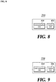
FIG. 9 is a block diagram of a base station according to at least one embodiment of the present disclosure. - Referring to
FIG. 9 , abase station 220 of an existing network according to some embodiments of the present disclosure includes acommunication unit 910 and acontrol unit 920. - The
communication unit 910 transmits the system information to the terminal 210. The system information includes information on whether or not the existingnetwork base station 220 supports an interworking service with the next-generation network. Thecommunication unit 910 transmits to the terminal 210, the system information including information on whether or not it supports the interworking service with the next-generation network, and it receives from the terminal 210, a connection establishment message including information on utilization of the next-generation network. - The
communication unit 910 relays the connection establishment message from the terminal 210 to the basestation control node 230. At this time, the connection establishment message may include information on utilization of the next-generation network. - The
communication unit 910 receives a connection acceptance message from the basestation control node 240. Thecommunication unit 810 receives the connection acceptance message, and receives the maximum data transfer rate for the next-generation network and the maximum data transfer rate of the existing network, too. - The
control unit 920 determines whether or not it supports interworking with the next-generation network. The existingnetwork base station 220 determines whether or not it supports interworking with the next-generation network based on information on whether the setting of the interface has been made relating to interworking with the next-generationnetwork base station 230, or information on whether the setting of interworking with the next-generation network has been made on the initial connection between thecore network 270 and the existingnetwork base station 220. - Upon receiving a connection establishment message from the terminal 210, the
control unit 920 determines whether or not the existingnetwork base station 220 supports interworking with the next-generation network. In case where the existingnetwork base station 220 supports interworking with the next-generation network, thecontrol unit 920 controls to include information on utilization of the next-generation network received from the terminal, in the connection establishment message. On the other hand, when the existingnetwork base station 220 does not support interworking with the next-generation network, thecontrol unit 920 controls not to include information on utilization of the next-generation network received from the terminal, in the connection establishment message. - The
control unit 920 decides, based on the resultant determination made previously, whether or not to transmit the connection acceptance message with the information on utilization of the next-generation network included. When not supporting interworking with the next-generation network, thecontrol unit 920 controls not to include information on utilization of the next-generation network in the connection establishment message. Conversely, when supporting the interworking with the next-generation network, thecontrol unit 920 controls to include information on utilization of the next-generation network in the connection establishment message. -
FIG. 10 is a block diagram of a base station control node according to at least one embodiment of the present disclosure. - Referring to
FIG. 10 , a basestation control node 240 according to some embodiments of the present disclosure includes acommunication unit 1010, acontrol unit 1020 and adata storage unit 1030. - The
communication unit 1010 receives from the terminal, a network connection establishment message including information on utilization of the next-generation network, and transmits a network connection establishment request message to the selected gateway. - The
control unit 1020 decides whether or not to permit the terminal 210 to utilize the next-generation network by using the information on utilization of the next-generation network and the information on theterminal 210. Thecontrol unit 1020 decides whether or not to permit the terminal 210 to utilize the next-generation network by taking account of whether the terminal 210 supports the next-generation network, whether or not it has requested utilization of the next-generation network, whether it subscribes to a service for utilization of the next-generation network, or whether or not it exceeds the usage limit of the next-generation network, among others. - The
data storage unit 1030 stores information on the terminal. The information on the terminal includes information on whether or not the terminal 210 is subscribing to a service for allowing the use of the next-generation network, and information on whether or not the terminal has exceeded the usage limit of the next-generation network. -
FIG. 11 is a block diagram of a gateway according to at least one embodiment of the present disclosure. - Referring to
FIG. 11 , acontrol plane gateway 250 according to some embodiments of the present disclosure includes acommunication unit 1110 and acontrol unit 1120. - The
communication unit 1110 receives from the basestation control node 240, a network connection establishment request message including information on utilization of the next-generation network by the terminal 210, and from the outside, information on the policy and charging on terminals. - The
communication unit 1110 transmits a flow table installation message to theuser plane gateway 260 so that traffic is transferred between the terminal 210 and theuser plane gateway 260. - The
communication unit 1110 transmits to the basestation control node 240, a connection acceptance message including the maximum data transfer rate for the next-generation network and the maximum data transfer rate for the existing network. - Referring to the information on utilization of the next-generation network by the terminal and the above information on the policy and charging, the
control unit 1120 determines the maximum data transfer rate for the next-generation network and the maximum data transfer rate for the existing network to be provided to the terminal 210, respectively. -
FIG. 12A is a flowchart of a process performed by a system architecture according to at least one embodiment of the present disclosure for transmission of information for utilizing a next-generation network over an existing network. - The existing
network base station 220 requests the terminal 210 to measure the configuration of the next-generation network (S1210). Specifically, the configuration of the next-generation network includes the frequency of the next-generation network being used, or the Physical Cell ID (PCID) of the next-generation network base station. - The terminal 210 measures the configuration of the next-generation network by way of interworking with the next-generation network base station 230 (S1215). Through interworking with the next-generation
network base station 230, the terminal 210 measures the frequency of the next-generation network, the strength of the signal transmitted/received, the PCID of the next-generation network base station, etc. - The terminal 210 transmits the resulting measurement to the existing network base station 220 (S1220).
- The existing
network base station 220 adds the measured next-generationnetwork base station 230 as a secondary base station (S1225). - The next-generation
network base station 230 approves the addition as the secondary base station and transmits a message of approval to the existing network base station 220 (S1230). - When the next-generation
network base station 230 is added as the secondary base station, the Radio Resource Control (RRC) between the terminal 210 and the existingnetwork base station 220 is reconfigured (S1235). - The existing
network base station 220 transmits to the next-generation network base station 230 a message notifying that the reconstruction of the RRC has been completed (S1240). - The next-generation
network base station 230 transfers a message notifying that it has been linked with the terminal 210 to an RRC management node 1203 (S1245). The message notifying the linkage with the terminal 210 includes the PCID of the next-generation network base station, the identifier of the terminal (User Entity ID or UEID), the reconfigured RRC, and the like. - The
RRC management node 1203 notifies theterminal 210 of the RRC of the next-generation network (S1250). The RRC information of the next-generation network includes the PCID of the next-generation network base station or the reconstructed RRC, etc. - The terminal 210 notifies the
RRC management node 1203 of the approval of the RRC of the next-generation network (S1255). - The
RRC management node 1203 notifies the next-generationnetwork base station 230 that the RRC of the next-generation network has been completed (S1260). -
FIG. 12B is a flowchart of a process performed by a system architecture according to another embodiment of the present disclosure for transmission of information for utilizing a next-generation network over an existing network. Steps S1270 to S1300 ofFIG. 12B are the same as Steps S1210 to S1240 ofFIG. 12A , and the description thereof will be omitted. - The terminal 210 transmits a query to a gateway/domain name system (DNS) 1206 (S1310). The query includes the domain name of the next-generation
network base station 230 or the PCID of the next-generationnetwork base station 230. - The gateway/
domain name system 1206 transmits a domain name response to the terminal 210 (S1315). The domain name response contains the IP address. - The terminal 210 transmits a message requesting the next-generation network RRC to the RRC management node 1203 (S1320). The message requesting the next-generation network RRC includes the PCID of the next-generation
network base station 230 or the identifier of the terminal (UEID). - The
RRC management node 1203 confirms whether or not to reconfigure the RRC at the next-generation network base station 230 (S1325). Through internal communications with the next-generationnetwork base station 230, theRRC management node 1203 confirms whether or not the RRC reconfiguration has been performed, whether or not the PCID of the next-generationnetwork base station 230 matches, or whether or not the terminal identifier (UEID) matches, etc. - The
RRC management node 1203 transmits a response message to the request of the next-generation network RRC, to the terminal 210 (S1330). TheRRC management node 1203 transmits a response message to the request of the next-generation network RRC based on the result of confirmation with the next-generationnetwork base station 230. -
FIG. 12C is a flowchart of a process performed by a system architecture according to yet another embodiment of the present disclosure for transmission of information for utilizing a next-generation network over an existing network. Steps S1340 to S1370 ofFIG. 12C are the same as Steps S1210 to S1240 ofFIG. 12A , and the description thereof will be omitted. - The terminal 210 transmits a message of packet data network (PDN) connection request to the base station control node 240 (S1375). The message of PDN connection request may include Access Point Name (APN) of the next-generation
network base station 230. - The terminal 210 and the base
station control node 240 transmit and receive an activate default bearer between each other (S1380). The activate default bearer may include the IP address of the terminal 210 or Protocol Configuration Option (PCO, the address of the base station control node). - The terminal 210 transmits a message requesting the next-generation network RRC to the RRC management node 1203 (S1385). The message requesting the next-generation network RRC includes the PCID of the next-generation
network base station 230 or the identifier of the terminal (UEID). - The
RRC management node 1203 confirms whether or not to reconfigure the RRC at the next-generation network base station 230 (S1390). Through the internal communication with the next-generationnetwork base station 230, theRRC management node 1203 confirms whether or not the RRC reconfiguration has been performed, whether or not the PCID of the next-generationnetwork base station 230 matches, or whether or not the terminal identifier (UEID) matches. - The
RRC management node 1203 transmits a response message to the request of the next-generation network RRC, to the terminal 210 (S1395). TheRRC management node 1203 transmits a response message to the request of the next-generation network RRC based on the result of confirmation with the next-generationnetwork base station 230. - Although the steps in
FIGS. 3 to 7 andFIGS. 12A to 12C are described to be sequentially performed, they merely instantiate the technical idea of some embodiments of the present disclosure. Therefore, a person having ordinary skill in the pertinent art could appreciate that various modifications, additions, and substitutions are possible by changing the sequences described in the respective drawings or by performing two or more of the steps in parallel, without departing from the gist and the nature of the embodiments of the present disclosure, and hence the steps inFIGS. 3 to 7 andFIGS. 12A to 12C are not limited to the illustrated chronological sequences. - The steps shown in
FIGS. 3 to 7 andFIGS. 12a to 12c can be implemented as computer-readable codes on a computer-readable recording medium. The computer-readable recording medium includes any type of recording device on which data that can be read by a computer system are recordable. Examples of the computer-readable recording medium include a magnetic recording medium (e.g., a ROM, a floppy disk, a hard disk, etc.), an optically readable medium (e.g., a CD-ROM, a DVD, etc.), and the like, and also include one implemented in the form of a carrier wave (e.g., transmission through the Internet). Further, the computer-readable recording medium can be distributed in computer systems connected via a network, wherein computer-readable codes can be stored and executed in a distributed mode. - Although exemplary embodiments of the present disclosure have been described for illustrative purposes, those skilled in the art will appreciate that various modifications, additions and substitutions are possible, without departing from the idea and scope of the claimed invention. Therefore, exemplary embodiments of the present disclosure have been described for the sake of brevity and clarity. The scope of the technical idea of the present embodiments is not limited by the illustrations. Accordingly, one of ordinary skill would understand the scope of the claimed invention is not to be limited by the above explicitly described embodiments but by the claims and equivalents thereof.
- This application claims priority under 35
U.S.C §119(a) of Patent Application No. 10-2016-0058193, filed on May 12, 2016
Claims (21)
- A method for controlling a base station by a base station control apparatus in a mobile communication system including a plurality of heterogeneous networks of different generations, the method comprising:receiving, by the base station control apparatus, a network connection establishment message including information on utilization of a first network from a terminal;deciding, by the base station control apparatus, whether to approve or disapprove utilization of the first network by the terminal by using previously stored information on the terminal and the information on utilization of the first network;selecting, by the base station control apparatus, one between a gateway capable of providing a mobile communication service based on the first network to the terminal, and a gateway capable of providing a second network to the terminal, depending on whether utilization of the first network is determined to be approved or disapproved; andperforming, by the base station control apparatus, a first transmission of a network connection establishment request message to the gateway selected in the selecting.
- The method of claim 1, wherein the first network comprises a fifth generation (5G) mobile communication network, and the second network comprises an earlier generation mobile communication network than the 5G mobile communication network.
- The method of claim 1, wherein the information on utilization of the first network includes information on whether the terminal supports the first network, whether the terminal requests utilization of the first network, or whether the terminal belongs to a service area for using the first network.
- The method of claim 3, wherein the deciding comprises:
approving utilization of the first network by the terminal, when the terminal supports the first network, the terminal requests utilization of the first network, and the terminal belongs to the service area for using the first network. - The method of claim 1, wherein the deciding comprises:
deciding whether to approve or disapprove utilization of the first network by the terminal, and additionally determining a maximum data transfer rate for the first network when utilization of the first network is determined to be approved, and a maximum data transfer rate for the second network when utilization of the first network is determined to be disapproved. - The method of claim 1, wherein the selecting comprises:selecting the gateway capable of providing the first network to the terminal when the deciding approves utilization of the first network by the terminal; andselecting the gateway capable of providing the second network to the terminal when the deciding disapproves utilization of the first network by the terminal.
- The method of claim 5 or 6, wherein the selecting comprises:
selecting of the gateway capable of providing the first network to the terminal, by taking account of whether the gateway is a gateway capable of supporting the maximum data transfer rate for the first network as determined by the determining, or whether the gateway is a gateway with a user plane and a control plane separated from each other. - The method of claim 3 or 5, wherein the performing of the first transmission comprises:
transmitting the network connection establishment request message after incorporating in the network connection establishment request message, the information on whether the terminal supports the first network, whether the terminal requests utilization of the first network, the maximum data transfer rate for the first network, and the maximum data transfer rate for the second network. - The method of claim 1, further comprising:performing a second transmission comprising:receiving, by the base station control apparatus, a connection acceptance message from a selected gateway, andtransmitting the connection acceptance message to the terminal,wherein the connection acceptance message includes a maximum data transfer rate for the first network and a maximum data transfer rate for the second network, which are determined by the selected gateway.
- An apparatus for controlling a base station in a mobile communication system including a plurality of heterogeneous networks of different generations, the apparatus comprising:a communication unit configured to receive from a terminal, a network connection establishment message including information on utilization of a first network, and to transmit a network connection establishment request message to a selected gateway;a data storage unit configured to store information on the terminal; anda control unit configured to decide whether to approve or disapprove utilization of the first network by the terminal by using the information on the terminal and the information on utilization of the first network, and to select one between a gateway capable of providing the first network to the terminal, and a gateway capable of providing a second network to the terminal, depending on whether utilization of the first network by the terminal is determined to be approved or disapproved.
- A method for determining a maximum data transfer rate by a control plane gateway in a mobile communication system including a plurality of heterogeneous networks of different generations, the method comprising:receiving, by the control plane gateway, information on a network connection establishment request including information on utilization of a first network by a terminal, from a base station control apparatus;determining, by the control plane gateway, a maximum data transfer rate for the first network and a maximum data transfer rate for the second network to be provided to the terminal, by referring to the information on the utilization of the first network by the terminal; andperforming a transmission by the control plane gateway, comprising:transmitting a flow table installation message to a user plane gateway so that traffic is transferred between the terminal and the user plane gateway, andtransmitting to the base station control apparatus, a connection acceptance message including a determined maximum data transfer rate for the first network and a determined maximum data transfer rate for the second network.
- The method of claim 11, wherein the information on the utilization of the first network by the terminal comprises:
the network connection establishment request which incorporates information on whether the terminal supports the first network, whether the terminal requests utilization of the first network, the maximum data transfer rate for the first network and the maximum data transfer rate for the second network. - A method for applying a maximum data transfer rate by a terminal in a mobile communication system including a plurality of heterogeneous networks of different generations, the method comprising:receiving, by the terminal, a maximum data transfer rate for a first network, a maximum data transfer rate for a second network, and a packet;performing, by the terminal, a first determination on whether or not the packet is a traffic that utilizes the first network;performing, by the terminal, a second determination on whether or not the mobile communication system is activated utilizing the first network; anddeciding, by the terminal, whether to control the traffic either by utilizing the first network by applying the maximum data transfer rate for the first network, or by utilizing the second network by applying the maximum data transfer rate for the second network, depending on results of the performing of the first determination and the performing of the second determination.
- The method of claim 13, wherein the deciding comprises:deciding to control the traffic by utilizing the first network by applying the maximum data transfer rate for the first network, when the packet is a traffic that utilizes the first network and the mobile communication system is activated utilizing the first network; anddeciding to control the traffic by utilizing the second network by applying the maximum data transfer rate for the second network, when the packet is not a traffic that utilizes the first network or the mobile communication system is not activated utilizing the first network.
- A terminal apparatus for applying a maximum data transfer rate in a mobile communication system including a plurality of heterogeneous networks of different generations, the terminal apparatus comprising:a communication unit configured to receive a maximum data transfer rate for a first network, a maximum data transfer rate for a second network, and a packet; anda control unit configured tomake decisions on whether or not the packet is a traffic that utilizes the first network and whether or not the mobile communication system is activated utilizing the first network, anddecide, depending on the results of the decisions, whether to control the traffic either by utilizing the first network by applying the maximum data transfer rate for the first network, or by utilizing the second network by applying the maximum data transfer rate for the second network.
- A method of operating a base station in a mobile communication system including a plurality of heterogeneous networks of different generations, the method comprising:receiving, by the base station, a network connection establishment message for a first network, including information on utilization of the first network from a terminal;determining whether or not the base station supports interworking with the first network upon receiving the connection establishment message;deciding whether to include the information on utilization of the first network in the connection establishment message depending on whether or not the base station supports interworking with the first network; andtransmitting a connection establishment message after the deciding, to a base station control apparatus.
- A base station apparatus in a mobile communication system including a plurality of heterogeneous networks of different generations, the base station apparatus comprising:a communication unit configured toreceive a connection establishment message for a first network, including information on utilization of the first network from a terminal, andtransmit a connection establishment message after deciding whether to incorporate the information on utilization of the first network, to a base station control apparatus; anda control unit configured todetermine, when the communication unit receives the connection establishment message, whether the control unit supports interworking with the first network, anddecide whether to include the information on the utilization of the first network in the connection establishment message depending on whether the control unit supports the interworking with the first network.
- A method for notifying whether a network is activated or deactivated in a mobile communication system including a plurality of networks of different generations, which are provided in an interworking arrangement respectively by a terminal, the method comprising:determining, by the terminal, whether a first network that is in connection with the terminal is inactivated;determining, by the terminal when the first network is inactivated, whether there is an uplink packet to be transmitted to a base station;transmitting, by the terminal when there is an uplink packet to be transmitted to the base station, the uplink packet with a state of the first network being incorporated in a header of the uplink packet, to the base station; andgenerating, by the terminal when there is no uplink packet to be transmitted to the base station, a dummy packet for notifying the state of the first network, and transmitting the dummy packet to the base station.
- The method of claim 18, wherein the determining of whether the first network is inactivated is performed by determining:whether there is at least a predetermined drop of strength of a signal exchanged between the terminal and the base station that provides the first network,whether there is no packet exchange for a predetermined time or longer between the terminal and the base station that provides the first network, orwhether there is at least a certain number of failed packet transmissions/receptions between the terminal and the base station that provides the first network.
- The method of claim 18, wherein the header of the uplink packet is configured to incorporate the state of the first network by marking the state of the first network in a DSCP/ECN field or a traffic class/flow label field in the header of the uplink packet.
- A method for notifying whether a network is activated or deactivated in a mobile communication system including a plurality of heterogeneous networks of different generations, which are provided in an interworking arrangement respectively by a base station, the method comprising:determining, by the base station, whether a first network that is in connection with the terminal is inactivated; andtransmitting, by the base station, information on whether the first network is inactivated to a base station control apparatus.
Priority Applications (1)
| Application Number | Priority Date | Filing Date | Title |
|---|---|---|---|
| EP22186368.1A EP4099664A1 (en) | 2016-05-12 | 2017-04-28 | Method and apparatus for providing next generation network service in heterogeneous network environment |
Applications Claiming Priority (2)
| Application Number | Priority Date | Filing Date | Title |
|---|---|---|---|
| KR1020160058193A KR102076816B1 (en) | 2016-05-12 | 2016-05-12 | Method and Apparatus for Providing Next Generation Network in Heterogeneous Network Environment |
| PCT/KR2017/004583 WO2017196014A1 (en) | 2016-05-12 | 2017-04-28 | Method and apparatus for providing next generation network service in heterogeneous network environment |
Related Child Applications (2)
| Application Number | Title | Priority Date | Filing Date |
|---|---|---|---|
| EP22186368.1A Division-Into EP4099664A1 (en) | 2016-05-12 | 2017-04-28 | Method and apparatus for providing next generation network service in heterogeneous network environment |
| EP22186368.1A Division EP4099664A1 (en) | 2016-05-12 | 2017-04-28 | Method and apparatus for providing next generation network service in heterogeneous network environment |
Publications (3)
| Publication Number | Publication Date |
|---|---|
| EP3445013A1 true EP3445013A1 (en) | 2019-02-20 |
| EP3445013A4 EP3445013A4 (en) | 2019-11-27 |
| EP3445013B1 EP3445013B1 (en) | 2022-09-14 |
Family
ID=60268001
Family Applications (2)
| Application Number | Title | Priority Date | Filing Date |
|---|---|---|---|
| EP17796314.7A Active EP3445013B1 (en) | 2016-05-12 | 2017-04-28 | Method and apparatus for providing next generation network service in heterogeneous network environment |
| EP22186368.1A Pending EP4099664A1 (en) | 2016-05-12 | 2017-04-28 | Method and apparatus for providing next generation network service in heterogeneous network environment |
Family Applications After (1)
| Application Number | Title | Priority Date | Filing Date |
|---|---|---|---|
| EP22186368.1A Pending EP4099664A1 (en) | 2016-05-12 | 2017-04-28 | Method and apparatus for providing next generation network service in heterogeneous network environment |
Country Status (7)
| Country | Link |
|---|---|
| US (3) | US10499445B2 (en) |
| EP (2) | EP3445013B1 (en) |
| JP (2) | JP2019515596A (en) |
| KR (1) | KR102076816B1 (en) |
| CN (2) | CN113452786A (en) |
| ES (1) | ES2929482T3 (en) |
| WO (1) | WO2017196014A1 (en) |
Families Citing this family (3)
| Publication number | Priority date | Publication date | Assignee | Title |
|---|---|---|---|---|
| EP3461216B1 (en) | 2016-06-30 | 2023-12-13 | Huawei Technologies Co., Ltd. | Multi-connection communication method and device |
| WO2019229935A1 (en) * | 2018-05-31 | 2019-12-05 | 楽天株式会社 | Information processing device, information processing method, program, and storage medium |
| US10827395B2 (en) * | 2018-09-18 | 2020-11-03 | Cisco Technology, Inc. | Methods and apparatus for selecting a serving gateway for a session of a user equipment (UE) in a mobile network having 5G non-standalone (NSA) architecture deployments |
Family Cites Families (44)
| Publication number | Priority date | Publication date | Assignee | Title |
|---|---|---|---|---|
| US7461248B2 (en) * | 2004-01-23 | 2008-12-02 | Nokia Corporation | Authentication and authorization in heterogeneous networks |
| JP4952240B2 (en) | 2006-12-27 | 2012-06-13 | 日本電気株式会社 | Radio base control station, mobile communication system, and priority cell selection method used therefor |
| GB2449923B (en) * | 2007-06-09 | 2011-09-28 | King's College London | Inter-working of networks |
| CN101552978B (en) | 2008-03-31 | 2011-04-13 | 华为技术有限公司 | Method, system and device for realizing route optimization |
| CN101552977B (en) * | 2008-03-31 | 2011-04-20 | 华为技术有限公司 | Load creating method and mobility management entity |
| EP2380392A1 (en) * | 2008-12-19 | 2011-10-26 | Telefonaktiebolaget LM Ericsson (publ) | Method and entity for conveying data units |
| KR101507171B1 (en) * | 2008-12-30 | 2015-03-31 | 엘지전자 주식회사 | Method of designating dual region |
| US20120250601A1 (en) * | 2011-03-28 | 2012-10-04 | Hyung-Nam Choi | Communication terminal, method for exchanging data, communication device and method for establishing a communication connection |
| KR20130001655A (en) * | 2011-06-27 | 2013-01-04 | 삼성전자주식회사 | Apparatus and method for providing service to different service terminal |
| US20130229931A1 (en) * | 2012-03-02 | 2013-09-05 | Electronics And Telecommunications Research Institute | Methods of managing terminal performed in base station and terminal |
| US8824976B2 (en) | 2012-04-11 | 2014-09-02 | Qualcomm Incorporated | Devices for switching an antenna |
| EP2912913A4 (en) * | 2012-10-26 | 2016-06-22 | Nokia Technologies Oy | Method and apparatus for management of multiple communication channels |
| US10091719B2 (en) * | 2012-11-23 | 2018-10-02 | Telefonaktiebolaget Lm Ericsson (Publ) | Methods and apparatus for enabling traffic steering between heterogeneous telecommunication networks |
| EP2961233B1 (en) * | 2013-02-22 | 2019-06-05 | NEC Corporation | Wireless station and communication control method |
| CN110087272B (en) | 2013-02-22 | 2021-10-08 | 三星电子株式会社 | Method and system for providing simultaneous connections between multiple E-node bs and user equipment |
| EP3349518B1 (en) * | 2013-04-01 | 2019-06-12 | Samsung Electronics Co., Ltd. | Location registration method and apparatus of terminal in mobile communication system |
| WO2014163450A1 (en) * | 2013-04-05 | 2014-10-09 | 엘지전자 주식회사 | Method for transmitting downlink signal of user equipment having dual connectivity in heterogeneous cell environment |
| EP2984871B1 (en) * | 2013-04-12 | 2020-08-26 | Nokia Solutions and Networks Oy | Pdcp operation for dual connection |
| US9526044B2 (en) * | 2013-05-08 | 2016-12-20 | Lg Electronics Inc. | Method of configuring dual connectivity to UE in heterogeneous cell deployment |
| US20140335882A1 (en) * | 2013-05-10 | 2014-11-13 | Electronics & Telecommunications Research Institute | Method for configuring dual connectivity |
| KR102104493B1 (en) * | 2013-05-10 | 2020-05-04 | 주식회사 팬택 | Method and apparatus of transmitting data in wireless communication system supporting dual connectivity |
| KR102091696B1 (en) * | 2013-08-08 | 2020-03-20 | 삼성전자주식회사 | Apparatus and method for perforing switching operation between macro cell and small cell in mobile communication system |
| US20150089382A1 (en) * | 2013-09-26 | 2015-03-26 | Wu-chi Feng | Application context migration framework and protocol |
| EP2959743B1 (en) * | 2013-10-28 | 2019-12-25 | LG Electronics Inc. | Method and apparatus for performing dual connectivity in heterogeneous network |
| WO2015069551A1 (en) | 2013-10-30 | 2015-05-14 | Interdigital Patent Holdings, Inc. | Coordinated packet data network change for selected internet protocol traffic offload |
| EP3065484B1 (en) * | 2013-10-31 | 2020-04-29 | Nec Corporation | Wireless communication system, base station device, and wireless terminal |
| US10028212B2 (en) * | 2013-11-22 | 2018-07-17 | Qualcomm Incorporated | Techniques for provisioning configuration information based on cell characteristics |
| CN104811984A (en) * | 2014-01-27 | 2015-07-29 | 中国移动通信集团公司 | Service quality management method, apparatus and system |
| CN105027617B (en) * | 2014-01-29 | 2020-04-28 | 华为技术有限公司 | Method and device for transmitting configuration message |
| CN104869661B (en) * | 2014-02-24 | 2018-05-22 | 普天信息技术有限公司 | A kind of method and system of service bearer |
| EP3117639A2 (en) | 2014-03-13 | 2017-01-18 | Interdigital Patent Holdings, Inc. | Local offload and small cell architecture (sca) |
| CN104936223B (en) * | 2014-03-21 | 2019-05-24 | 上海诺基亚贝尔股份有限公司 | Enhancing is measured to implement the method for dual link to the cell in closed state |
| CN106063360B (en) * | 2014-03-28 | 2020-11-03 | 富士通株式会社 | Bearer management apparatus, method and communication system |
| DE102014104538A1 (en) | 2014-03-31 | 2015-10-01 | Intel Corporation | COMMUNICATION TERMINALS, COMMUNICATION DEVICE, METHOD FOR CREATING A COMMUNICATION, FOR DETERMINING COMMUNICATION CONNECTIONS FOR COMMUNICATION AND FOR CARRYING OUT A COMMUNICATION |
| US9537743B2 (en) * | 2014-04-25 | 2017-01-03 | International Business Machines Corporation | Maximizing storage controller bandwidth utilization in heterogeneous storage area networks |
| EP3146759B1 (en) * | 2014-05-19 | 2021-04-07 | Nokia Solutions and Networks Oy | Re-establishment procedure in dual connectivity networks |
| WO2015183004A1 (en) * | 2014-05-29 | 2015-12-03 | 엘지전자 주식회사 | Method for supporting dual connectivity and device using same |
| US20170127473A1 (en) * | 2014-06-24 | 2017-05-04 | Nokia Technologies Oy | Dual connectivity management |
| CN105338653A (en) * | 2014-08-07 | 2016-02-17 | 北京三星通信技术研究有限公司 | Method and equipment supporting UE bearing recovery |
| WO2016047374A1 (en) | 2014-09-25 | 2016-03-31 | シャープ株式会社 | Terminal device, mme, and control method |
| WO2016122367A1 (en) * | 2015-01-30 | 2016-08-04 | Telefonaktiebolaget Lm Ericsson (Publ) | Network nodes and methods therein for handover for dual connectivity |
| EP3297382B1 (en) * | 2015-05-15 | 2021-01-20 | Samsung Electronics Co., Ltd. | Methods and devices for transmitting or receiving scheduling request in mobile communication system |
| CN105050124B (en) * | 2015-09-01 | 2018-07-17 | 重庆邮电大学 | Frequency spectrum resource polymerization between station of the isomery cellular network based on service-aware |
| WO2017203956A1 (en) * | 2016-05-26 | 2017-11-30 | 日本電気株式会社 | Communication system, control device, communication terminal, communication device, and communication method |
-
2016
- 2016-05-12 KR KR1020160058193A patent/KR102076816B1/en active IP Right Grant
-
2017
- 2017-04-28 ES ES17796314T patent/ES2929482T3/en active Active
- 2017-04-28 CN CN202110720040.3A patent/CN113452786A/en active Pending
- 2017-04-28 EP EP17796314.7A patent/EP3445013B1/en active Active
- 2017-04-28 EP EP22186368.1A patent/EP4099664A1/en active Pending
- 2017-04-28 JP JP2018559759A patent/JP2019515596A/en active Pending
- 2017-04-28 WO PCT/KR2017/004583 patent/WO2017196014A1/en active Application Filing
- 2017-04-28 CN CN201780028882.4A patent/CN109196835B/en active Active
-
2018
- 2018-11-09 US US16/186,010 patent/US10499445B2/en active Active
-
2019
- 2019-10-23 US US16/661,415 patent/US10873988B2/en active Active
-
2020
- 2020-10-01 US US17/061,021 patent/US11412564B2/en active Active
- 2020-10-15 JP JP2020173691A patent/JP7128874B2/en active Active
Also Published As
| Publication number | Publication date |
|---|---|
| CN109196835B (en) | 2021-07-16 |
| JP2021005905A (en) | 2021-01-14 |
| EP3445013B1 (en) | 2022-09-14 |
| US20210022196A1 (en) | 2021-01-21 |
| KR102076816B1 (en) | 2020-02-12 |
| US20190082486A1 (en) | 2019-03-14 |
| US10873988B2 (en) | 2020-12-22 |
| KR20170127727A (en) | 2017-11-22 |
| US10499445B2 (en) | 2019-12-03 |
| EP3445013A4 (en) | 2019-11-27 |
| CN109196835A (en) | 2019-01-11 |
| US11412564B2 (en) | 2022-08-09 |
| EP4099664A1 (en) | 2022-12-07 |
| CN113452786A (en) | 2021-09-28 |
| JP7128874B2 (en) | 2022-08-31 |
| ES2929482T3 (en) | 2022-11-29 |
| US20200059984A1 (en) | 2020-02-20 |
| JP2019515596A (en) | 2019-06-06 |
| WO2017196014A1 (en) | 2017-11-16 |
Similar Documents
| Publication | Publication Date | Title |
|---|---|---|
| US10609608B2 (en) | Method for changing connection mode in base station, and base station therefor, and method for changing connection mode in user equipment, and user equipment thereof | |
| US10206147B2 (en) | Serving gateway relocation and secondary node eligibility for dual connectivity | |
| EP3145228B1 (en) | Method and apparatus for signal transmission and reception of hss/mme in wireless communication system | |
| WO2021073314A1 (en) | Method for data transmission, communication device, and communication system | |
| CN113225782A (en) | System and method for session management | |
| US11553546B2 (en) | Methods and systems for radio access network aggregation and uniform control of multi-RAT networks | |
| US10623990B2 (en) | User equipment and method for transmitting data, and network node and method for receiving data | |
| US11412564B2 (en) | Method and apparatus for providing next generation network service in heterogeneous network environment | |
| US11937319B2 (en) | Integrity protection handling at the gNB-CU-UP | |
| WO2019105378A1 (en) | Communication method and communication device | |
| CN110505714B (en) | Multi-link communication method, equipment and terminal | |
| WO2017219355A1 (en) | Multi-connection communications method and device | |
| US9503393B2 (en) | S-GW relocation and QoS change without mobility | |
| JP2017509267A (en) | Cross system network information interaction method, terminal system network element | |
| US10701591B2 (en) | Data transmission method, apparatus, and system | |
| US20240031253A1 (en) | Method for radio access network visible quality of experience measurement of dual connectivity | |
| US20230354136A1 (en) | Integrated access and backhaul communication method and apparatus | |
| US20220116798A1 (en) | Data transmission method, apparatus, and device | |
| WO2020238596A1 (en) | Handover method, apparatus and communications system | |
| WO2014000611A1 (en) | Method and device for transmitting data | |
| KR101851327B1 (en) | Method and apparatus for providing communication service between mobile terminals |
Legal Events
| Date | Code | Title | Description |
|---|---|---|---|
| STAA | Information on the status of an ep patent application or granted ep patent |
Free format text: STATUS: THE INTERNATIONAL PUBLICATION HAS BEEN MADE |
|
| PUAI | Public reference made under article 153(3) epc to a published international application that has entered the european phase |
Free format text: ORIGINAL CODE: 0009012 |
|
| STAA | Information on the status of an ep patent application or granted ep patent |
Free format text: STATUS: REQUEST FOR EXAMINATION WAS MADE |
|
| 17P | Request for examination filed |
Effective date: 20181112 |
|
| AK | Designated contracting states |
Kind code of ref document: A1 Designated state(s): AL AT BE BG CH CY CZ DE DK EE ES FI FR GB GR HR HU IE IS IT LI LT LU LV MC MK MT NL NO PL PT RO RS SE SI SK SM TR |
|
| AX | Request for extension of the european patent |
Extension state: BA ME |
|
| DAV | Request for validation of the european patent (deleted) | ||
| DAX | Request for extension of the european patent (deleted) | ||
| A4 | Supplementary search report drawn up and despatched |
Effective date: 20191028 |
|
| RIC1 | Information provided on ipc code assigned before grant |
Ipc: H04W 76/15 20180101ALI20191022BHEP Ipc: H04L 29/08 20060101ALI20191022BHEP Ipc: H04L 29/06 20060101AFI20191022BHEP Ipc: H04L 1/18 20060101ALI20191022BHEP |
|
| STAA | Information on the status of an ep patent application or granted ep patent |
Free format text: STATUS: EXAMINATION IS IN PROGRESS |
|
| 17Q | First examination report despatched |
Effective date: 20200923 |
|
| STAA | Information on the status of an ep patent application or granted ep patent |
Free format text: STATUS: EXAMINATION IS IN PROGRESS |
|
| STAA | Information on the status of an ep patent application or granted ep patent |
Free format text: STATUS: EXAMINATION IS IN PROGRESS |
|
| REG | Reference to a national code |
Ref country code: DE Ref legal event code: R079 Ref document number: 602017061823 Country of ref document: DE Free format text: PREVIOUS MAIN CLASS: H04L0029060000 Ipc: H04L0067141000 |
|
| RIC1 | Information provided on ipc code assigned before grant |
Ipc: H04W 76/16 20180101ALI20220315BHEP Ipc: H04L 65/40 20220101ALI20220315BHEP Ipc: H04L 67/141 20220101AFI20220315BHEP |
|
| GRAP | Despatch of communication of intention to grant a patent |
Free format text: ORIGINAL CODE: EPIDOSNIGR1 |
|
| STAA | Information on the status of an ep patent application or granted ep patent |
Free format text: STATUS: GRANT OF PATENT IS INTENDED |
|
| INTG | Intention to grant announced |
Effective date: 20220425 |
|
| GRAS | Grant fee paid |
Free format text: ORIGINAL CODE: EPIDOSNIGR3 |
|
| GRAA | (expected) grant |
Free format text: ORIGINAL CODE: 0009210 |
|
| STAA | Information on the status of an ep patent application or granted ep patent |
Free format text: STATUS: THE PATENT HAS BEEN GRANTED |
|
| AK | Designated contracting states |
Kind code of ref document: B1 Designated state(s): AL AT BE BG CH CY CZ DE DK EE ES FI FR GB GR HR HU IE IS IT LI LT LU LV MC MK MT NL NO PL PT RO RS SE SI SK SM TR |
|
| REG | Reference to a national code |
Ref country code: GB Ref legal event code: FG4D |
|
| REG | Reference to a national code |
Ref country code: CH Ref legal event code: EP |
|
| REG | Reference to a national code |
Ref country code: DE Ref legal event code: R096 Ref document number: 602017061823 Country of ref document: DE |
|
| REG | Reference to a national code |
Ref country code: IE Ref legal event code: FG4D |
|
| REG | Reference to a national code |
Ref country code: AT Ref legal event code: REF Ref document number: 1519389 Country of ref document: AT Kind code of ref document: T Effective date: 20221015 |
|
| REG | Reference to a national code |
Ref country code: ES Ref legal event code: FG2A Ref document number: 2929482 Country of ref document: ES Kind code of ref document: T3 Effective date: 20221129 |
|
| REG | Reference to a national code |
Ref country code: NL Ref legal event code: FP |
|
| REG | Reference to a national code |
Ref country code: LT Ref legal event code: MG9D |
|
| PG25 | Lapsed in a contracting state [announced via postgrant information from national office to epo] |
Ref country code: SE Free format text: LAPSE BECAUSE OF FAILURE TO SUBMIT A TRANSLATION OF THE DESCRIPTION OR TO PAY THE FEE WITHIN THE PRESCRIBED TIME-LIMIT Effective date: 20220914 Ref country code: RS Free format text: LAPSE BECAUSE OF FAILURE TO SUBMIT A TRANSLATION OF THE DESCRIPTION OR TO PAY THE FEE WITHIN THE PRESCRIBED TIME-LIMIT Effective date: 20220914 Ref country code: NO Free format text: LAPSE BECAUSE OF FAILURE TO SUBMIT A TRANSLATION OF THE DESCRIPTION OR TO PAY THE FEE WITHIN THE PRESCRIBED TIME-LIMIT Effective date: 20221214 Ref country code: LV Free format text: LAPSE BECAUSE OF FAILURE TO SUBMIT A TRANSLATION OF THE DESCRIPTION OR TO PAY THE FEE WITHIN THE PRESCRIBED TIME-LIMIT Effective date: 20220914 Ref country code: LT Free format text: LAPSE BECAUSE OF FAILURE TO SUBMIT A TRANSLATION OF THE DESCRIPTION OR TO PAY THE FEE WITHIN THE PRESCRIBED TIME-LIMIT Effective date: 20220914 Ref country code: FI Free format text: LAPSE BECAUSE OF FAILURE TO SUBMIT A TRANSLATION OF THE DESCRIPTION OR TO PAY THE FEE WITHIN THE PRESCRIBED TIME-LIMIT Effective date: 20220914 |
|
| REG | Reference to a national code |
Ref country code: AT Ref legal event code: MK05 Ref document number: 1519389 Country of ref document: AT Kind code of ref document: T Effective date: 20220914 |
|
| PG25 | Lapsed in a contracting state [announced via postgrant information from national office to epo] |
Ref country code: HR Free format text: LAPSE BECAUSE OF FAILURE TO SUBMIT A TRANSLATION OF THE DESCRIPTION OR TO PAY THE FEE WITHIN THE PRESCRIBED TIME-LIMIT Effective date: 20220914 Ref country code: GR Free format text: LAPSE BECAUSE OF FAILURE TO SUBMIT A TRANSLATION OF THE DESCRIPTION OR TO PAY THE FEE WITHIN THE PRESCRIBED TIME-LIMIT Effective date: 20221215 |
|
| PG25 | Lapsed in a contracting state [announced via postgrant information from national office to epo] |
Ref country code: SM Free format text: LAPSE BECAUSE OF FAILURE TO SUBMIT A TRANSLATION OF THE DESCRIPTION OR TO PAY THE FEE WITHIN THE PRESCRIBED TIME-LIMIT Effective date: 20220914 Ref country code: RO Free format text: LAPSE BECAUSE OF FAILURE TO SUBMIT A TRANSLATION OF THE DESCRIPTION OR TO PAY THE FEE WITHIN THE PRESCRIBED TIME-LIMIT Effective date: 20220914 Ref country code: PT Free format text: LAPSE BECAUSE OF FAILURE TO SUBMIT A TRANSLATION OF THE DESCRIPTION OR TO PAY THE FEE WITHIN THE PRESCRIBED TIME-LIMIT Effective date: 20230116 Ref country code: CZ Free format text: LAPSE BECAUSE OF FAILURE TO SUBMIT A TRANSLATION OF THE DESCRIPTION OR TO PAY THE FEE WITHIN THE PRESCRIBED TIME-LIMIT Effective date: 20220914 Ref country code: AT Free format text: LAPSE BECAUSE OF FAILURE TO SUBMIT A TRANSLATION OF THE DESCRIPTION OR TO PAY THE FEE WITHIN THE PRESCRIBED TIME-LIMIT Effective date: 20220914 |
|
| PGFP | Annual fee paid to national office [announced via postgrant information from national office to epo] |
Ref country code: FR Payment date: 20230309 Year of fee payment: 7 |
|
| PG25 | Lapsed in a contracting state [announced via postgrant information from national office to epo] |
Ref country code: SK Free format text: LAPSE BECAUSE OF FAILURE TO SUBMIT A TRANSLATION OF THE DESCRIPTION OR TO PAY THE FEE WITHIN THE PRESCRIBED TIME-LIMIT Effective date: 20220914 Ref country code: PL Free format text: LAPSE BECAUSE OF FAILURE TO SUBMIT A TRANSLATION OF THE DESCRIPTION OR TO PAY THE FEE WITHIN THE PRESCRIBED TIME-LIMIT Effective date: 20220914 Ref country code: IS Free format text: LAPSE BECAUSE OF FAILURE TO SUBMIT A TRANSLATION OF THE DESCRIPTION OR TO PAY THE FEE WITHIN THE PRESCRIBED TIME-LIMIT Effective date: 20230114 Ref country code: EE Free format text: LAPSE BECAUSE OF FAILURE TO SUBMIT A TRANSLATION OF THE DESCRIPTION OR TO PAY THE FEE WITHIN THE PRESCRIBED TIME-LIMIT Effective date: 20220914 |
|
| PGFP | Annual fee paid to national office [announced via postgrant information from national office to epo] |
Ref country code: IT Payment date: 20230310 Year of fee payment: 7 |
|
| REG | Reference to a national code |
Ref country code: DE Ref legal event code: R097 Ref document number: 602017061823 Country of ref document: DE |
|
| PG25 | Lapsed in a contracting state [announced via postgrant information from national office to epo] |
Ref country code: AL Free format text: LAPSE BECAUSE OF FAILURE TO SUBMIT A TRANSLATION OF THE DESCRIPTION OR TO PAY THE FEE WITHIN THE PRESCRIBED TIME-LIMIT Effective date: 20220914 |
|
| P01 | Opt-out of the competence of the unified patent court (upc) registered |
Effective date: 20230602 |
|
| PLBE | No opposition filed within time limit |
Free format text: ORIGINAL CODE: 0009261 |
|
| STAA | Information on the status of an ep patent application or granted ep patent |
Free format text: STATUS: NO OPPOSITION FILED WITHIN TIME LIMIT |
|
| PG25 | Lapsed in a contracting state [announced via postgrant information from national office to epo] |
Ref country code: DK Free format text: LAPSE BECAUSE OF FAILURE TO SUBMIT A TRANSLATION OF THE DESCRIPTION OR TO PAY THE FEE WITHIN THE PRESCRIBED TIME-LIMIT Effective date: 20220914 |
|
| PGFP | Annual fee paid to national office [announced via postgrant information from national office to epo] |
Ref country code: ES Payment date: 20230512 Year of fee payment: 7 Ref country code: DE Payment date: 20230307 Year of fee payment: 7 |
|
| 26N | No opposition filed |
Effective date: 20230615 |
|
| PG25 | Lapsed in a contracting state [announced via postgrant information from national office to epo] |
Ref country code: SI Free format text: LAPSE BECAUSE OF FAILURE TO SUBMIT A TRANSLATION OF THE DESCRIPTION OR TO PAY THE FEE WITHIN THE PRESCRIBED TIME-LIMIT Effective date: 20220914 |
|
| PGFP | Annual fee paid to national office [announced via postgrant information from national office to epo] |
Ref country code: TR Payment date: 20230426 Year of fee payment: 7 |
|
| REG | Reference to a national code |
Ref country code: CH Ref legal event code: PL |
|
| PG25 | Lapsed in a contracting state [announced via postgrant information from national office to epo] |
Ref country code: LU Free format text: LAPSE BECAUSE OF NON-PAYMENT OF DUE FEES Effective date: 20230428 |
|
| REG | Reference to a national code |
Ref country code: BE Ref legal event code: MM Effective date: 20230430 |
|
| PG25 | Lapsed in a contracting state [announced via postgrant information from national office to epo] |
Ref country code: MC Free format text: LAPSE BECAUSE OF FAILURE TO SUBMIT A TRANSLATION OF THE DESCRIPTION OR TO PAY THE FEE WITHIN THE PRESCRIBED TIME-LIMIT Effective date: 20220914 |
|
| PG25 | Lapsed in a contracting state [announced via postgrant information from national office to epo] |
Ref country code: MC Free format text: LAPSE BECAUSE OF FAILURE TO SUBMIT A TRANSLATION OF THE DESCRIPTION OR TO PAY THE FEE WITHIN THE PRESCRIBED TIME-LIMIT Effective date: 20220914 Ref country code: LI Free format text: LAPSE BECAUSE OF NON-PAYMENT OF DUE FEES Effective date: 20230430 Ref country code: CH Free format text: LAPSE BECAUSE OF NON-PAYMENT OF DUE FEES Effective date: 20230430 |
|
| REG | Reference to a national code |
Ref country code: IE Ref legal event code: MM4A |
|
| PG25 | Lapsed in a contracting state [announced via postgrant information from national office to epo] |
Ref country code: BE Free format text: LAPSE BECAUSE OF NON-PAYMENT OF DUE FEES Effective date: 20230430 |
|
| PG25 | Lapsed in a contracting state [announced via postgrant information from national office to epo] |
Ref country code: IE Free format text: LAPSE BECAUSE OF NON-PAYMENT OF DUE FEES Effective date: 20230428 |
|
| PGFP | Annual fee paid to national office [announced via postgrant information from national office to epo] |
Ref country code: NL Payment date: 20240315 Year of fee payment: 8 |
|
| PG25 | Lapsed in a contracting state [announced via postgrant information from national office to epo] |
Ref country code: IE Free format text: LAPSE BECAUSE OF NON-PAYMENT OF DUE FEES Effective date: 20230428 |
|
| PGFP | Annual fee paid to national office [announced via postgrant information from national office to epo] |
Ref country code: GB Payment date: 20240307 Year of fee payment: 8 |