EP3444948A1 - Response force generation device - Google Patents
Response force generation device Download PDFInfo
- Publication number
- EP3444948A1 EP3444948A1 EP18186971.0A EP18186971A EP3444948A1 EP 3444948 A1 EP3444948 A1 EP 3444948A1 EP 18186971 A EP18186971 A EP 18186971A EP 3444948 A1 EP3444948 A1 EP 3444948A1
- Authority
- EP
- European Patent Office
- Prior art keywords
- drive
- waveform
- response force
- force generation
- signal
- Prior art date
- Legal status (The legal status is an assumption and is not a legal conclusion. Google has not performed a legal analysis and makes no representation as to the accuracy of the status listed.)
- Ceased
Links
Images




Classifications
-
- B—PERFORMING OPERATIONS; TRANSPORTING
- B06—GENERATING OR TRANSMITTING MECHANICAL VIBRATIONS IN GENERAL
- B06B—METHODS OR APPARATUS FOR GENERATING OR TRANSMITTING MECHANICAL VIBRATIONS OF INFRASONIC, SONIC, OR ULTRASONIC FREQUENCY, e.g. FOR PERFORMING MECHANICAL WORK IN GENERAL
- B06B1/00—Methods or apparatus for generating mechanical vibrations of infrasonic, sonic, or ultrasonic frequency
- B06B1/02—Methods or apparatus for generating mechanical vibrations of infrasonic, sonic, or ultrasonic frequency making use of electrical energy
- B06B1/04—Methods or apparatus for generating mechanical vibrations of infrasonic, sonic, or ultrasonic frequency making use of electrical energy operating with electromagnetism
- B06B1/045—Methods or apparatus for generating mechanical vibrations of infrasonic, sonic, or ultrasonic frequency making use of electrical energy operating with electromagnetism using vibrating magnet, armature or coil system
-
- B—PERFORMING OPERATIONS; TRANSPORTING
- B06—GENERATING OR TRANSMITTING MECHANICAL VIBRATIONS IN GENERAL
- B06B—METHODS OR APPARATUS FOR GENERATING OR TRANSMITTING MECHANICAL VIBRATIONS OF INFRASONIC, SONIC, OR ULTRASONIC FREQUENCY, e.g. FOR PERFORMING MECHANICAL WORK IN GENERAL
- B06B1/00—Methods or apparatus for generating mechanical vibrations of infrasonic, sonic, or ultrasonic frequency
- B06B1/02—Methods or apparatus for generating mechanical vibrations of infrasonic, sonic, or ultrasonic frequency making use of electrical energy
- B06B1/0207—Driving circuits
- B06B1/0215—Driving circuits for generating pulses, e.g. bursts of oscillations, envelopes
-
- G—PHYSICS
- G06—COMPUTING OR CALCULATING; COUNTING
- G06F—ELECTRIC DIGITAL DATA PROCESSING
- G06F3/00—Input arrangements for transferring data to be processed into a form capable of being handled by the computer; Output arrangements for transferring data from processing unit to output unit, e.g. interface arrangements
- G06F3/01—Input arrangements or combined input and output arrangements for interaction between user and computer
- G06F3/016—Input arrangements with force or tactile feedback as computer generated output to the user
-
- G—PHYSICS
- G06—COMPUTING OR CALCULATING; COUNTING
- G06F—ELECTRIC DIGITAL DATA PROCESSING
- G06F3/00—Input arrangements for transferring data to be processed into a form capable of being handled by the computer; Output arrangements for transferring data from processing unit to output unit, e.g. interface arrangements
- G06F3/01—Input arrangements or combined input and output arrangements for interaction between user and computer
- G06F3/03—Arrangements for converting the position or the displacement of a member into a coded form
- G06F3/041—Digitisers, e.g. for touch screens or touch pads, characterised by the transducing means
-
- H—ELECTRICITY
- H03—ELECTRONIC CIRCUITRY
- H03K—PULSE TECHNIQUE
- H03K4/00—Generating pulses having essentially a finite slope or stepped portions
- H03K4/06—Generating pulses having essentially a finite slope or stepped portions having triangular shape
- H03K4/08—Generating pulses having essentially a finite slope or stepped portions having triangular shape having sawtooth shape
-
- H—ELECTRICITY
- H03—ELECTRONIC CIRCUITRY
- H03K—PULSE TECHNIQUE
- H03K4/00—Generating pulses having essentially a finite slope or stepped portions
- H03K4/94—Generating pulses having essentially a finite slope or stepped portions having trapezoidal shape
-
- G—PHYSICS
- G06—COMPUTING OR CALCULATING; COUNTING
- G06F—ELECTRIC DIGITAL DATA PROCESSING
- G06F2203/00—Indexing scheme relating to G06F3/00 - G06F3/048
- G06F2203/041—Indexing scheme relating to G06F3/041 - G06F3/045
- G06F2203/04105—Pressure sensors for measuring the pressure or force exerted on the touch surface without providing the touch position
Definitions
- the present invention relates to a response force generation device that makes a response force generation mechanism to apply a response force to a member to be operated when an operation unit provided in the member to be operated is operated with a finger or the like.
- Patent Literature 1 describes the invention relating to an image forming device having an operation panel vibration means configured to vibrate a touch panel.
- This image forming device has an LCD and the touch panel positioned on the LCD, and a key is displayed on the LCD.
- a key selection detection means detects that the touch panel is pressed with a finger or the like as the key displayed on the LCD is selected, the selected key is analyzed by a CPU. Based on this analysis, a time at which vibration is started is set by a vibration start time setting means, a frequency to be vibrated is set by a vibration frequency setting means, and a vibration waveform is set by a vibration waveform setting means, whereby vibration is applied to the touch panel.
- the vibration waveform setting means sets a vibration waveform of a sine wave, a vibration waveform of a rectangular wave, or a vibration waveform of a triangular wave.
- Patent Literature 1 JP 2006-150865 A
- a triangular wave as the vibration waveform, to increase the vibration frequency of the triangular wave, and to increase the amplitude of the triangular wave.
- a driver circuit power amplifier
- the present invention has been made in view of the above-described conventional problems, and an object thereof is to provide a response force generation device capable of causing a response force of a large acceleration to act on a member to be operated with a large amplitude from a response force generation mechanism.
- a response force generation device including: a response force generation mechanism which is attached to a member to be operated at least a part of which is configured as an operation unit and applies a response force to the member to be operated; and a drive control unit configured to drive the response force generation mechanism, in which the response force generation mechanism has a movable portion and a magnetic drive unit configured to operate the movable portion, the drive control unit sets a drive waveform for changing a signal intensity of a drive signal to be supplied to the magnetic drive unit, and the drive waveform has a first drive section in which the signal intensity increases in accordance with a lapse of time and a second drive section including a peak of the signal intensity, and the second drive section includes a region in which an increase rate of the signal intensity with respect to time is lower than an increase rate of the first drive section.
- the drive signal change linearly in the first drive section.
- a waveform of the drive signal is a rectangular wave in the second drive section.
- the second drive section can be configured to include a region in which the intensity of the drive signal does not change.
- the second drive section may include a region in which the intensity of the drive signal changes in a curve.
- the increase rate of the signal intensity with respect to time is set to be lower than that of the first drive section in the second drive section including the peak of the drive signal to be applied to the magnetic drive unit of the response force generation mechanism.
- follow-up characteristics of a driver including a power amplifier to the drive signal becomes favorable, so that it is possible to apply a high peak voltage to a drive coil of the magnetic drive unit.
- Figs. 1 , 2 , and 3 illustrate a display/operation device 1 as an example of a member to be operated on which a response force generation device according to an embodiment of the present invention is mounted.
- the display/operation device 1 is mounted on a vehicle.
- the display/operation device 1 which is the member to be operated, has a panel portion 2 on the front side and a casing portion 3 on the rear side.
- a front surface of the panel portion 2 is configured as a decorative surface 2a.
- a display panel such as a color liquid crystal display panel or an electroluminescence display panel is housed inside the casing portion 3 and a display screen 4 provided on the display panel appears at a central portion of the decorative surface 2a.
- a transparent touch sensor is superimposed on a surface of the display screen 4, and at least a part of the display screen 4 is configured as an operation unit.
- the touch sensor is a capacitive sensor in which a plurality of transparent electrodes are provided on a transparent substrate. When a human finger touches the display screen 4, an electrostatic capacitance detected by the electrode changes, and a position touched by the finger is detected.
- the touch sensor is a resistive sensor in which a transparent film having transparent electrode formed on the entire surface thereof is superimposed on a transparent substrate similarly having transparent electrode formed on the entire surface thereof.
- the transparent electrode formed on the transparent film and the transparent electrode formed on the transparent substrate are short-circuited, a change in a resistance value from an electrode portion provided at an edge of the transparent electrode to a short-circuited portion is detected, and a position touched by a finger is determined.
- operation units 5 and 6 are provided on the decorative surface 2a of the panel portion 2 in a region in which the display screen 4 is not provided.
- the operation units 5 and 6 are configured using thin film switches obtained by providing electrodes on opposing faces of a substrate and a surface film, the surface and the surface film opposing each other.
- capacitive or resistive touch sensors similar to that arranged on the front side of the display screen 4 may be provided in the operation units 5 and 6.
- the casing portion 3 is a metal case made of a rolled steel plate, aluminum, or the like, and the panel portion 2 is fixed to the front of the casing portion 3 with a screw or the like.
- the display panel, a circuit board, and the like are housed inside the casing portion 3.
- the response force generation mechanism 10 is fixed to a back surface of the casing portion 3 of the display/operation device 1.
- the response force generation mechanism 10 is fixed inside the casing portion 3.
- the response force generation mechanism 10 has a housing 11 which is fixed to the casing portion 3.
- the housing 11 is a box made of a sheet metal material.
- a movable portion 12 having a predetermined mass is provided inside the housing 11.
- the movable portion 12 is supported by an elastic support member 13 so as to be movable in a direction (Y direction) orthogonal to a plane direction of the decorative surface 2a of the panel portion 2.
- the movable portion 12 is made of a magnetic metal material such as a Ni-Fe alloy.
- the elastic support member 13 is a leaf spring or a compression coil spring made of a nonmagnetic material.
- a pair of magnets 14 opposing both longitudinal end portions (both end portions facing an X direction) of the movable portion 12 are fixed inside the housing 11.
- an opposing surface facing the movable portion 12 is a magnetized face.
- the magnetized face is magnetized with an N pole and an S pole divided in the Y direction.
- magnetic poles opposite to each other oppose each other in the X direction.
- a drive coil 15 is wound around the movable portion 12, and a magnet drive unit is constituted by the magnets 14 and 14 and the drive coil 15.
- an operation direction P using a finger is indicated by an arrow.
- the panel portion 2 is pressed in the direction P with the finger, a drive current flows through the drive coil 15 in the response force generation mechanism 10, the movable portion 12 is driven in the Y direction, and as a reaction force thereof, a response force whose direction of force is the Y direction is applied to the display/operation device 1.
- the movable portion 12 may be driven in the X direction, and a response force whose direction of force is the X direction may be applied to the display/operation device 1 in a magnetic drive mechanism.
- the display/operation device 1 is installed on an instrument panel 20 of the vehicle. As illustrated in Figs. 1 and 2 , a rectangular opening 21 is formed in the instrument panel 20, and the display/operation device 1 is installed inside the opening 21. As illustrated in Fig. 2 , a base 22 is provided inside the opening 21 of the instrument panel 20. The base 22 is a part of a vehicle body structural portion or an internal structural portion of the instrument panel 20. The casing portion 3 of the display/operation device 1 is supported by a plurality of support metal plates (support members) 23 in front of the base 22.
- the support metal plate 23 is made of a metal plate having a certain degree of elasticity, and is made of, for example, a cold-rolled steel plate or a stainless steel plate. Due to the elastic deformation of the support metal plate 23, the display/operation device 1 slightly moves in the Y direction.
- a metal bracket 24 is fixed to the base 22, and a plurality of detection members 25 are attached to a face of the metal bracket 24 facing the front side in the Y direction.
- the detection member 25 is a force sensor or a proximity sensor.
- the force sensor is constituted by an elastically deforming portion that deforms by receiving an operating force P acting on the display/operation device 1 and a strain gauge that detects deformation of the elastically deforming portion.
- the proximity sensor is constituted by a magnet provided on a back surface of the casing portion 3 and a magnetic sensor provided on the metal bracket 24 and detecting a change in distance with respect to the magnet.
- the response force generation device is constituted by the response force generation mechanism 10 fixed to the display/operation device 1 and a drive control unit 30 illustrated in Fig. 4 .
- a drive waveform setting unit 31 is provided in the drive control unit 30.
- the drive control unit 30 is provided with a computer, and the drive waveform setting unit 31 is computer software installed in the computer.
- the drive waveform setting unit 31 is referred to as waveform generation software, signal waveform setting software, or the like, and the drive waveform setting unit 31 sets a drive waveform representing an intensity change of a drive signal with respect to time.
- the drive control unit 30 is provided with a D/A converter 32 such that the drive waveform, which is a digital signal set by the drive waveform setting unit 31, is converted into an analog value.
- the drive waveform converted into the analog value is applied to a driver circuit 33 having the power amplifier, and a drive current is amplified by the driver circuit 33 is applied to the drive coil 15 provided in the magnetic drive unit of the response force generation mechanism 10.
- any part of an image that is being displayed has been touched by the finger is determined based on a coordinate detection output from the touch sensor while referring to the image displayed on the display screen 4 of the panel portion 2.
- the support metal plate 23 elastically deforms, the display/operation device 1 slightly moves in the Y direction, and the press of the display/operation device 1 is detected by the detection member 25.
- any operation that has been performed is determined by referring to the image displayed on the display screen 4 based on the detection output of the touch sensor and the detection output of the detection member 25, and a processing operation based on an intended operation is started.
- the drive control unit 30 When the detection member 25 detects a load based on the operating force P, an operation command is issued to the drive control unit 30 illustrated in Fig. 4 by the main body control unit.
- the drive signal set by the drive waveform setting unit 31 is converted into an analog signal by the D/A converter 32, and the drive current is applied from the driver circuit 33 to the drive coil 15 provided in the response force generation mechanism 10.
- the response force generation mechanism 10 the movable portion 12 is moved in the Y direction by the drive current flowing through the drive coil 15 and a magnetic field of the magnet 14 constituting the magnetic drive unit, and a reaction force of the movement of the movable portion 12 in the Y direction is applied to the display/operation device 1, so that the operating finger feels a response force.
- the drive control unit 30 is operated as necessary to apply the response force to the display/operation device 1 from the response force generation mechanism 10.
- Fig. 5A illustrates a drive waveform (i) of a drive signal of a first embodiment set by the drive waveform setting unit 31 with a solid line.
- a drive current corresponding to a change in the drive waveform (i) is applied from the driver circuit 33 to the drive coil 15 of the response force generation mechanism 10.
- An alternate long and short dash line illustrated in Fig. 5A is a change (ii) of a voltage acting on the drive coil 15 when the drive current flows.
- Fig. 5B illustrates a drive waveform (iii) of the drive signal as a comparative example and a change (iv) of a voltage acting on the drive coil 15.
- a drive current based on the drive waveform (i) set by the drive waveform setting unit 31 is applied to the drive coil 15 for one period at a timing at which the detection member 25 detects the operating force P.
- the drive current may be applied for a plurality of periods at the above-described timing.
- the drive waveform (i) set by the drive waveform setting unit 31 includes a first drive section T1, a second drive section T2, and a third drive section T3.
- the first drive section T1 is a region (a) where a signal intensity of the drive signal increases with a lapse of time. As illustrated in Fig. 5A , it is preferable that the signal intensity increase linearly in the first drive section T1. However, a waveform in which the signal intensity increases in a curve may be included in the first drive section T1.
- the second drive section T2 includes a peak (+P) on a positive side of the signal intensity.
- the second drive section T2 includes a region (b) where the drive signal abruptly rises (with a vertical waveform) and a region (c) where the signal intensity does not change but retains a value of the peak (+P) even after a lapse of time.
- the second drive section T2 includes the region (c) where an increase rate of the signal intensity with respect to time is lower than that in the first drive section T1.
- the third drive section T3 also includes a region (e) where the signal intensity does not change and remains the peak (-P) even after a lapse of time and a region (d) where the drive signal abruptly rises (with a vertical waveform).
- the signal intensity of the drive signal changes at a higher change rate than that in the first drive section T1, and a drive waveform thereof changes substantially along the vertical waveform from the positive-side peak (+P) to a negative-side peak (-P) for almost zero time.
- the drive waveform (i) of the drive signal illustrated in Fig. 5A can be obtained by combining a so-called sawtooth wave (triangular wave) in which changes in signal regions (a) and (f) are repeated and a rectangular wave such as a change of the signal intensity in the second drive section T2 between the negative-side peak (-P) and the positive-side peak (+P) in the drive waveform setting unit 31.
- a so-called sawtooth wave triangular wave
- a rectangular wave such as a change of the signal intensity in the second drive section T2 between the negative-side peak (-P) and the positive-side peak (+P) in the drive waveform setting unit 31.
- a drive waveform of a drive signal is a so-called sawtooth wave (triangular wave)
- a signal intensity of the drive signal linearly increases from a negative-side peak (-P) to a positive-side peak (+P) at a time T0
- the signal intensity changes along a vertical waveform from the positive-side peak (+P) to the negative-side peak (-P).
- the signal intensities at the positive-side peak (+P) and the negative-side peak (- P) are the same in the first embodiment of Fig. 5A and the comparative example of Fig. 5B .
- an increase rate of the drive signal with respect to a lapse of time in the first drive section T1 of the drive waveform (i) is the same as an increase rate of the drive signal with respect to a lapse of time in the drive waveform (iii) at the time T0, and both the drive signal change linearly.
- the signal intensity of the drive waveform (iii) shows the increase rate of the linear function towards the positive-side peak (+P), and the waveform has a shape that is sharp at a distal end of a blade at positive-side peak (+P) while the drive waveform (i) is the rectangular wave.
- the peak value (+P) of the signal intensity is retained in the region (c) of the second drive section T2, and the increase rate of the signal intensity with respect to the lapse of time in the second drive section T2 is lower than that in the first drive section T1 in the drive waveform (i) of Fig. 5A .
- the increase rate of signal intensity in the second drive section T2 is the same as that in the first drive section T1.
- the drive waveform (i) illustrated in Fig. 5A more easily follows frequency characteristics of the driver circuit 33 illustrated in Fig. 4 than the drive waveform (iii) illustrated in Fig. 5B .
- an integral value obtained by integrating signal intensities with time in the second drive section T2 of the drive waveform (i) in Fig. 5A is larger than as an integral value similarly obtained in the second drive section T2 of the drive waveform (iii) of Fig. 5B .
- the drive waveform (i) can increase power (drive energy) to be applied to the drive coil 15 in the vicinity of the positive-side peak (+P) as compared with the drive waveform (iii).
- the change of the signal intensity of the drive signal in the third drive section T3 is gentler than that in the first drive section T1 as illustrated in Fig. 5A .
- an integral value obtained by integrating signal intensities with time in Fig. 5A is larger than an integral value similarly obtained in the vicinity of the negative-side peak (-P) of the drive waveform (iii) in Fig. 5B .
- a voltage Va acting on the drive coil 15 when a drive current is caused to flow to the drive coil 15 using the drive waveform (i) of the first embodiment illustrated in Fig. 5A can be set to be larger than a voltage Vb acting on the drive coil 15 when the drive waveform (iii) of the comparative example illustrated in Fig. 5B is used. Accordingly, it is possible to increase the kinetic energy in the Y direction to be applied to the movable portion 12 and to drive the movable portion 12 with a large acceleration within a defined amplitude in the response force generation mechanism 10 illustrated in Fig. 3 . Since the kinetic energy of the movable portion 12 is large, it is possible to apply the reaction force with respect to the movement of the movable portion 12 as a large force to the display/operation device 1.
- the drive waveform is set such that the increase rate of the signal intensity in the first drive section T1 is high and a rise angle of the straight line of the linear function is large, so that it is possible to apply a responsive force with a sharp feeling and a large force to the finger operating the display screen 4 or the operation units 5 and 6 even if the mass of the display/operation device 1 is large.
- the response force with a feeling, which is similar to a feeling obtained when a mechanical switch having a dome type reversing contact is pressed by a finger to operate, to the finger applying the operating force P.
- Fig. 6A illustrates a drive waveform (v) of a drive signal of a second embodiment
- Fig. 6B illustrates a drive waveform (vi) of a drive signal of a third embodiment.
- a signal intensity changes with a curve trajectory with respect to a lapse of time in the second drive section T2, and an increase rate of the signal intensity in the second drive section T2 is lower than an increase rate in the first drive section T1.
- the similar description is also applied in the third drive section T3.
- the member to be operated is the display/operation device 1 in the above-described embodiment, the member to be operated is not limited thereto.
- a part of an instrument panel provided in a passenger compartment of an automobile may be a member to be operated provided with a capacitive sensor.
Landscapes
- Engineering & Computer Science (AREA)
- General Engineering & Computer Science (AREA)
- Theoretical Computer Science (AREA)
- Physics & Mathematics (AREA)
- Human Computer Interaction (AREA)
- General Physics & Mathematics (AREA)
- Mechanical Engineering (AREA)
- Electromagnetism (AREA)
- User Interface Of Digital Computer (AREA)
- Instrument Panels (AREA)
Abstract

Description
- The present invention relates to a response force generation device that makes a response force generation mechanism to apply a response force to a member to be operated when an operation unit provided in the member to be operated is operated with a finger or the like.
-
Patent Literature 1 describes the invention relating to an image forming device having an operation panel vibration means configured to vibrate a touch panel. - This image forming device has an LCD and the touch panel positioned on the LCD, and a key is displayed on the LCD. When a key selection detection means detects that the touch panel is pressed with a finger or the like as the key displayed on the LCD is selected, the selected key is analyzed by a CPU. Based on this analysis, a time at which vibration is started is set by a vibration start time setting means, a frequency to be vibrated is set by a vibration frequency setting means, and a vibration waveform is set by a vibration waveform setting means, whereby vibration is applied to the touch panel.
- As illustrated in
Fig. 2 ofPatent Literature 1, the vibration waveform setting means sets a vibration waveform of a sine wave, a vibration waveform of a rectangular wave, or a vibration waveform of a triangular wave. - Patent Literature 1:
JP 2006-150865 A - When the mass of an operation panel formed of the LCD and the touch panel is relatively small, it is possible to make the finger touching the touch panel relatively easily feel a response force with respect to the pressing of the touch panel by using the vibration waveform of the sine wave or the rectangular wave and properly setting the vibration frequency.
- However, when it is desired to apply a large response force to the operation panel having a relatively large mass, or when it is desired to apply a large operation reaction force similar to a response force when a mechanical switch is pressed to an operating finger, the vibration waveform of the sine wave or the rectangular wave is often insufficient.
- In order to apply a response force having a large acceleration to the operation panel, it is preferable to select a triangular wave as the vibration waveform, to increase the vibration frequency of the triangular wave, and to increase the amplitude of the triangular wave. However, if the a of a drive waveform of a triangular wave is increased and a waveform of a peak portion of the triangular wave is set to a sharp shape, it is difficult for frequency characteristic of a driver circuit (power amplifier) provided in the operation panel vibration means to follow a change in the intensity of a peak region of the triangular wave in the drive waveform, and a growth of a voltage acting on a drive coil is more likely to become dull in the vicinity of the peak of the triangular wave. In addition, it is difficult to apply a sufficient acceleration to a movable portion in a vibration generation unit due to influence of an impedance of the drive coil provided in the vibration generation unit, an inertia force of the movable portion to be operated by the drive coil, and the like.
- The present invention has been made in view of the above-described conventional problems, and an object thereof is to provide a response force generation device capable of causing a response force of a large acceleration to act on a member to be operated with a large amplitude from a response force generation mechanism.
- The invention relates to a response force generation device according to the appended claims. Embodiments are disclosed in the dependent claims.
According to an aspect, there is disclosed a response force generation device including: a response force generation mechanism which is attached to a member to be operated at least a part of which is configured as an operation unit and applies a response force to the member to be operated; and a drive control unit configured to drive the response force generation mechanism, in which the response force generation mechanism has a movable portion and a magnetic drive unit configured to operate the movable portion, the drive control unit sets a drive waveform for changing a signal intensity of a drive signal to be supplied to the magnetic drive unit, and the drive waveform has a first drive section in which the signal intensity increases in accordance with a lapse of time and a second drive section including a peak of the signal intensity, and the second drive section includes a region in which an increase rate of the signal intensity with respect to time is lower than an increase rate of the first drive section. - In the response force generation device of the present invention, it is preferable that the drive signal change linearly in the first drive section.
- In the response force generation device of the present invention, for example, a waveform of the drive signal is a rectangular wave in the second drive section.
- That is, the second drive section can be configured to include a region in which the intensity of the drive signal does not change.
- In the response force generation device of the present invention, the second drive section may include a region in which the intensity of the drive signal changes in a curve.
- In the response force generation device of the present invention, the increase rate of the signal intensity with respect to time is set to be lower than that of the first drive section in the second drive section including the peak of the drive signal to be applied to the magnetic drive unit of the response force generation mechanism. Thus, when the signal intensity reaches the peak, follow-up characteristics of a driver including a power amplifier to the drive signal becomes favorable, so that it is possible to apply a high peak voltage to a drive coil of the magnetic drive unit. Thus, it is possible to give a drive force of a large acceleration to the movable portion of the response force generation mechanism and the member to be operated with a relatively large amplitude, and it is possible to apply a responsive force with a sharp change in force to the member to be operated.
- Therefore, even if the mass of the member to be operated is relatively large, it is possible to apply a sharp response force to the operating finger.
-
Fig. 1 is an external perspective view illustrating an embodiment of the present invention and illustrating a display/operation device as an example of a member to be operated. -
Fig. 2 is a cross-sectional view illustrating a state where the display/operation device illustrated inFig. 1 is attached to an instrument panel of an automobile and obtained by cuttingFig. 1 along a line II-II. -
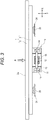
Fig. 3 is an explanatory view schematically illustrating a structure of a response force generation mechanism attached to the display/operation device which is the member to be operated. -
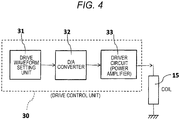
Fig. 4 is a circuit block diagram illustrating a drive control unit that drives the response force generation mechanism. -
Fig. 5A is a waveform diagram illustrating a drive waveform of a first embodiment set by the drive control unit, andFig. 5B is a waveform diagram illustrating a drive waveform of a comparative example. -
Fig. 6A is a waveform diagram illustrating a drive waveform of a second embodiment set by the drive control unit, andFig. 6B is a waveform diagram illustrating a drive waveform of a third embodiment set by the drive control unit. -
Figs. 1 ,2 , and3 illustrate a display/operation device 1 as an example of a member to be operated on which a response force generation device according to an embodiment of the present invention is mounted. The display/operation device 1 is mounted on a vehicle. - The display/
operation device 1, which is the member to be operated, has apanel portion 2 on the front side and acasing portion 3 on the rear side. A front surface of thepanel portion 2 is configured as adecorative surface 2a. A display panel such as a color liquid crystal display panel or an electroluminescence display panel is housed inside thecasing portion 3 and adisplay screen 4 provided on the display panel appears at a central portion of thedecorative surface 2a. - A transparent touch sensor is superimposed on a surface of the
display screen 4, and at least a part of thedisplay screen 4 is configured as an operation unit. The touch sensor is a capacitive sensor in which a plurality of transparent electrodes are provided on a transparent substrate. When a human finger touches thedisplay screen 4, an electrostatic capacitance detected by the electrode changes, and a position touched by the finger is detected. Alternatively, the touch sensor is a resistive sensor in which a transparent film having transparent electrode formed on the entire surface thereof is superimposed on a transparent substrate similarly having transparent electrode formed on the entire surface thereof. When any point of the transparent film is pressed in the resistive sensor, the transparent electrode formed on the transparent film and the transparent electrode formed on the transparent substrate are short-circuited, a change in a resistance value from an electrode portion provided at an edge of the transparent electrode to a short-circuited portion is detected, and a position touched by a finger is determined. - As illustrated in
Fig. 1 ,operation units decorative surface 2a of thepanel portion 2 in a region in which thedisplay screen 4 is not provided. Theoperation units display screen 4 may be provided in theoperation units - The
casing portion 3 is a metal case made of a rolled steel plate, aluminum, or the like, and thepanel portion 2 is fixed to the front of thecasing portion 3 with a screw or the like. The display panel, a circuit board, and the like are housed inside thecasing portion 3. - As illustrated in
Fig. 3 , the responseforce generation mechanism 10 is fixed to a back surface of thecasing portion 3 of the display/operation device 1. Alternatively, the responseforce generation mechanism 10 is fixed inside thecasing portion 3. - The response
force generation mechanism 10 has ahousing 11 which is fixed to thecasing portion 3. Thehousing 11 is a box made of a sheet metal material. Amovable portion 12 having a predetermined mass is provided inside thehousing 11. Themovable portion 12 is supported by anelastic support member 13 so as to be movable in a direction (Y direction) orthogonal to a plane direction of thedecorative surface 2a of thepanel portion 2. Themovable portion 12 is made of a magnetic metal material such as a Ni-Fe alloy. Theelastic support member 13 is a leaf spring or a compression coil spring made of a nonmagnetic material. A pair ofmagnets 14 opposing both longitudinal end portions (both end portions facing an X direction) of themovable portion 12 are fixed inside thehousing 11. - In each of the pair of
magnets movable portion 12 is a magnetized face. The magnetized face is magnetized with an N pole and an S pole divided in the Y direction. On the magnetized faces of the pair ofmagnets drive coil 15 is wound around themovable portion 12, and a magnet drive unit is constituted by themagnets drive coil 15. - In
Figs. 1 to 3 , an operation direction P using a finger is indicated by an arrow. When thepanel portion 2 is pressed in the direction P with the finger, a drive current flows through thedrive coil 15 in the responseforce generation mechanism 10, themovable portion 12 is driven in the Y direction, and as a reaction force thereof, a response force whose direction of force is the Y direction is applied to the display/operation device 1. Incidentally, themovable portion 12 may be driven in the X direction, and a response force whose direction of force is the X direction may be applied to the display/operation device 1 in a magnetic drive mechanism. - The display/
operation device 1 is installed on aninstrument panel 20 of the vehicle. As illustrated inFigs. 1 and2 , arectangular opening 21 is formed in theinstrument panel 20, and the display/operation device 1 is installed inside theopening 21. As illustrated inFig. 2 , abase 22 is provided inside theopening 21 of theinstrument panel 20. Thebase 22 is a part of a vehicle body structural portion or an internal structural portion of theinstrument panel 20. Thecasing portion 3 of the display/operation device 1 is supported by a plurality of support metal plates (support members) 23 in front of thebase 22. Thesupport metal plate 23 is made of a metal plate having a certain degree of elasticity, and is made of, for example, a cold-rolled steel plate or a stainless steel plate. Due to the elastic deformation of thesupport metal plate 23, the display/operation device 1 slightly moves in the Y direction. - As illustrated in
Figs. 2 and3 , ametal bracket 24 is fixed to thebase 22, and a plurality ofdetection members 25 are attached to a face of themetal bracket 24 facing the front side in the Y direction. Thedetection member 25 is a force sensor or a proximity sensor. The force sensor is constituted by an elastically deforming portion that deforms by receiving an operating force P acting on the display/operation device 1 and a strain gauge that detects deformation of the elastically deforming portion. The proximity sensor is constituted by a magnet provided on a back surface of thecasing portion 3 and a magnetic sensor provided on themetal bracket 24 and detecting a change in distance with respect to the magnet. - In the embodiment of the present invention, the response force generation device is constituted by the response
force generation mechanism 10 fixed to the display/operation device 1 and adrive control unit 30 illustrated inFig. 4 . - As illustrated in
Fig. 4 , a drivewaveform setting unit 31 is provided in thedrive control unit 30. Thedrive control unit 30 is provided with a computer, and the drivewaveform setting unit 31 is computer software installed in the computer. For example, the drivewaveform setting unit 31 is referred to as waveform generation software, signal waveform setting software, or the like, and the drivewaveform setting unit 31 sets a drive waveform representing an intensity change of a drive signal with respect to time. - The
drive control unit 30 is provided with a D/A converter 32 such that the drive waveform, which is a digital signal set by the drivewaveform setting unit 31, is converted into an analog value. The drive waveform converted into the analog value is applied to adriver circuit 33 having the power amplifier, and a drive current is amplified by thedriver circuit 33 is applied to thedrive coil 15 provided in the magnetic drive unit of the responseforce generation mechanism 10. - Next, an operation of the response force generation device will be described.
- When a finger touches any point of the
display screen 4 in the display/operation device 1, any part of an image that is being displayed has been touched by the finger is determined based on a coordinate detection output from the touch sensor while referring to the image displayed on thedisplay screen 4 of thepanel portion 2. When the operating force P is applied to thedisplay screen 4 with the finger, thesupport metal plate 23 elastically deforms, the display/operation device 1 slightly moves in the Y direction, and the press of the display/operation device 1 is detected by thedetection member 25. In a main body control unit (not illustrated), any operation that has been performed is determined by referring to the image displayed on thedisplay screen 4 based on the detection output of the touch sensor and the detection output of thedetection member 25, and a processing operation based on an intended operation is started. - When the
detection member 25 detects a load based on the operating force P, an operation command is issued to thedrive control unit 30 illustrated inFig. 4 by the main body control unit. In thedrive control unit 30, the drive signal set by the drivewaveform setting unit 31 is converted into an analog signal by the D/A converter 32, and the drive current is applied from thedriver circuit 33 to thedrive coil 15 provided in the responseforce generation mechanism 10. In the responseforce generation mechanism 10, themovable portion 12 is moved in the Y direction by the drive current flowing through thedrive coil 15 and a magnetic field of themagnet 14 constituting the magnetic drive unit, and a reaction force of the movement of themovable portion 12 in the Y direction is applied to the display/operation device 1, so that the operating finger feels a response force. - Incidentally, even when the
operation units Fig. 1 are pressed, thedrive control unit 30 is operated as necessary to apply the response force to the display/operation device 1 from the responseforce generation mechanism 10. -
Fig. 5A illustrates a drive waveform (i) of a drive signal of a first embodiment set by the drivewaveform setting unit 31 with a solid line. A drive current corresponding to a change in the drive waveform (i) is applied from thedriver circuit 33 to thedrive coil 15 of the responseforce generation mechanism 10. An alternate long and short dash line illustrated inFig. 5A is a change (ii) of a voltage acting on thedrive coil 15 when the drive current flows. -
Fig. 5B illustrates a drive waveform (iii) of the drive signal as a comparative example and a change (iv) of a voltage acting on thedrive coil 15. - In the response force generation device, a drive current based on the drive waveform (i) set by the drive
waveform setting unit 31 is applied to thedrive coil 15 for one period at a timing at which thedetection member 25 detects the operating force P. Alternatively, the drive current may be applied for a plurality of periods at the above-described timing. - The drive waveform (i) set by the drive
waveform setting unit 31 includes a first drive section T1, a second drive section T2, and a third drive section T3. The first drive section T1 is a region (a) where a signal intensity of the drive signal increases with a lapse of time. As illustrated inFig. 5A , it is preferable that the signal intensity increase linearly in the first drive section T1. However, a waveform in which the signal intensity increases in a curve may be included in the first drive section T1. - The second drive section T2 includes a peak (+P) on a positive side of the signal intensity. The second drive section T2 includes a region (b) where the drive signal abruptly rises (with a vertical waveform) and a region (c) where the signal intensity does not change but retains a value of the peak (+P) even after a lapse of time. The second drive section T2 includes the region (c) where an increase rate of the signal intensity with respect to time is lower than that in the first drive section T1.
- The third drive section T3 also includes a region (e) where the signal intensity does not change and remains the peak (-P) even after a lapse of time and a region (d) where the drive signal abruptly rises (with a vertical waveform).
- Regarding a drive signal (f) between the second drive section T2 and the third drive section T3, the signal intensity of the drive signal changes at a higher change rate than that in the first drive section T1, and a drive waveform thereof changes substantially along the vertical waveform from the positive-side peak (+P) to a negative-side peak (-P) for almost zero time.
- The drive waveform (i) of the drive signal illustrated in
Fig. 5A can be obtained by combining a so-called sawtooth wave (triangular wave) in which changes in signal regions (a) and (f) are repeated and a rectangular wave such as a change of the signal intensity in the second drive section T2 between the negative-side peak (-P) and the positive-side peak (+P) in the drivewaveform setting unit 31. - In the comparative example illustrated in
Fig. 5B , a drive waveform of a drive signal is a so-called sawtooth wave (triangular wave), a signal intensity of the drive signal linearly increases from a negative-side peak (-P) to a positive-side peak (+P) at a time T0, and the signal intensity changes along a vertical waveform from the positive-side peak (+P) to the negative-side peak (-P). - The signal intensities at the positive-side peak (+P) and the negative-side peak (- P) are the same in the first embodiment of
Fig. 5A and the comparative example ofFig. 5B . - When comparing the drive waveform (i) of the drive signal of the first embodiment illustrated in
Fig. 5A with a drive waveform (iii) of the drive signal of the comparative example illustrated inFig. 5B , an increase rate of the drive signal with respect to a lapse of time in the first drive section T1 of the drive waveform (i) is the same as an increase rate of the drive signal with respect to a lapse of time in the drive waveform (iii) at the time T0, and both the drive signal change linearly. - When comparing the change of the signal intensity in the second drive section T2 between the drive waveform (i) of the drive signal of the first embodiment and the drive waveform (iii) of the comparative example, the signal intensity of the drive waveform (iii) shows the increase rate of the linear function towards the positive-side peak (+P), and the waveform has a shape that is sharp at a distal end of a blade at positive-side peak (+P) while the drive waveform (i) is the rectangular wave.
- That is, the peak value (+P) of the signal intensity is retained in the region (c) of the second drive section T2, and the increase rate of the signal intensity with respect to the lapse of time in the second drive section T2 is lower than that in the first drive section T1 in the drive waveform (i) of
Fig. 5A . In the drive waveform (iii) ofFig. 5B , however, the increase rate of signal intensity in the second drive section T2 is the same as that in the first drive section T1. Thus, the drive waveform (i) illustrated inFig. 5A more easily follows frequency characteristics of thedriver circuit 33 illustrated inFig. 4 than the drive waveform (iii) illustrated inFig. 5B . - In addition, an integral value obtained by integrating signal intensities with time in the second drive section T2 of the drive waveform (i) in
Fig. 5A is larger than as an integral value similarly obtained in the second drive section T2 of the drive waveform (iii) ofFig. 5B . Thus, the drive waveform (i) can increase power (drive energy) to be applied to thedrive coil 15 in the vicinity of the positive-side peak (+P) as compared with the drive waveform (iii). - Similarly, the change of the signal intensity of the drive signal in the third drive section T3 is gentler than that in the first drive section T1 as illustrated in
Fig. 5A . Even in the third drive section T3, an integral value obtained by integrating signal intensities with time inFig. 5A is larger than an integral value similarly obtained in the vicinity of the negative-side peak (-P) of the drive waveform (iii) inFig. 5B . - As a result, a voltage Va acting on the
drive coil 15 when a drive current is caused to flow to thedrive coil 15 using the drive waveform (i) of the first embodiment illustrated inFig. 5A can be set to be larger than a voltage Vb acting on thedrive coil 15 when the drive waveform (iii) of the comparative example illustrated inFig. 5B is used. Accordingly, it is possible to increase the kinetic energy in the Y direction to be applied to themovable portion 12 and to drive themovable portion 12 with a large acceleration within a defined amplitude in the responseforce generation mechanism 10 illustrated inFig. 3 . Since the kinetic energy of themovable portion 12 is large, it is possible to apply the reaction force with respect to the movement of themovable portion 12 as a large force to the display/operation device 1. - Further, it is possible to increase the operating speed of the
movable portion 12 if the drive waveform is set such that the increase rate of the signal intensity in the first drive section T1 is high and a rise angle of the straight line of the linear function is large, so that it is possible to apply a responsive force with a sharp feeling and a large force to the finger operating thedisplay screen 4 or theoperation units operation device 1 is large. As a result, it is also possible to apply the response force with a feeling, which is similar to a feeling obtained when a mechanical switch having a dome type reversing contact is pressed by a finger to operate, to the finger applying the operating force P. -
Fig. 6A illustrates a drive waveform (v) of a drive signal of a second embodiment, andFig. 6B illustrates a drive waveform (vi) of a drive signal of a third embodiment. - In the drive waveform (v) illustrated in
Fig. 6A , a signal intensity changes with a curve trajectory with respect to a lapse of time in the second drive section T2, and an increase rate of the signal intensity in the second drive section T2 is lower than an increase rate in the first drive section T1. The similar description is also applied in the third drive section T3. - In the drive waveform (vi) illustrated in
Fig. 6B , a value of the positive-side peak (+P) is retained for a predetermined time in the second drive section T2. Therefore, an increase rate of the signal intensity in the second drive section T2 is lower than an increase rate in the first drive section T1. The similar description is also applied in the third drive section T3. - Even when the drive waveforms illustrated in
Figs. 6A and 6B are used, it is possible to increase a voltage to be applied to thedrive coil 15, and it is possible to make the finger feel a response force as if the mechanical switch was operated by operating themovable portion 12 with a large acceleration. - Although the member to be operated is the display/
operation device 1 in the above-described embodiment, the member to be operated is not limited thereto. For example, a part of an instrument panel provided in a passenger compartment of an automobile may be a member to be operated provided with a capacitive sensor. -
- 1
- Display/operation device
- 2
- Panel portion
- 3
- Casing portion
- 4
- Display screen
- 10
- Response force generation mechanism
- 11
- Housing
- 12
- Movable portion
- 13
- Elastic support member
- 14
- Magnet
- 15
- Drive coil
- 30
- Drive control unit
- 31
- Drive waveform setting unit
- 33
- Driver circuit
- T1
- First drive section
- T2
- Second drive section
- T3
- Third drive section
- (i)(v)(vi)
- Drive waveform
Claims (5)
- A response force generation device comprising:a response force generation mechanism (10) which is attached to a member to be operated (1) at least a part of which is configured as an operation unit and applies a response force to the member to be operated (1);a drive control unit (30) configured to drive the response force generation mechanism (10),wherein the response force generation mechanism (10) has a movable portion (12) and a magnetic drive unit (15) configured to operate the movable portion (12),the drive control unit (30) configured to set a drive waveform for changing a signal intensity of a drive signal to be supplied to the magnetic drive unit (15), whereinthe drive waveform has a first drive section (T1) in which the signal intensity increases in accordance with a lapse of time and a second drive section (T2) including a peak of the signal intensity, and the second drive section (T2) includes a region in which an increase rate of the signal intensity with respect to time is lower than an increase rate of the first drive section (T1).
- The response force generation device according to claim 1, wherein
the drive signal changes linearly in the first drive section (T1). - The response force generation device according to claim 1 or 2, wherein
a waveform of the drive signal is a rectangular wave in the second drive section (T2). - The response force generation device according to any one of claims 1 to 3, wherein
the second drive section (T2) includes a region in which the intensity of the drive signal does not change. - The response force generation device according to one of claims 1 to 4, wherein
the second drive section (T2) includes a region in which the intensity of the drive signal changes in a curve.
Applications Claiming Priority (1)
| Application Number | Priority Date | Filing Date | Title |
|---|---|---|---|
| JP2017157434A JP6866041B2 (en) | 2017-08-17 | 2017-08-17 | Response force generator |
Publications (1)
| Publication Number | Publication Date |
|---|---|
| EP3444948A1 true EP3444948A1 (en) | 2019-02-20 |
Family
ID=63293919
Family Applications (1)
| Application Number | Title | Priority Date | Filing Date |
|---|---|---|---|
| EP18186971.0A Ceased EP3444948A1 (en) | 2017-08-17 | 2018-08-02 | Response force generation device |
Country Status (3)
| Country | Link |
|---|---|
| US (1) | US10639674B2 (en) |
| EP (1) | EP3444948A1 (en) |
| JP (1) | JP6866041B2 (en) |
Cited By (2)
| Publication number | Priority date | Publication date | Assignee | Title |
|---|---|---|---|---|
| EP4089508A1 (en) * | 2021-05-11 | 2022-11-16 | Alps Alpine Co., Ltd. | Input device |
| EP4364862A1 (en) * | 2022-11-02 | 2024-05-08 | Grewus GmbH | Operation element with exciter spring |
Families Citing this family (3)
| Publication number | Priority date | Publication date | Assignee | Title |
|---|---|---|---|---|
| DE112019007239T5 (en) * | 2019-04-22 | 2022-01-13 | Mitsubishi Electric Corporation | Touch panel supporting structure and electronic device |
| US20220179254A1 (en) * | 2019-05-29 | 2022-06-09 | Mitsubishi Electric Corporation | Display apparatus |
| JP7454383B2 (en) | 2020-01-18 | 2024-03-22 | アルパイン株式会社 | operating device |
Citations (5)
| Publication number | Priority date | Publication date | Assignee | Title |
|---|---|---|---|---|
| EP0710899A1 (en) * | 1994-11-03 | 1996-05-08 | Asulab S.A. | Watch with time indication by non-sonic vibrations |
| US20020149561A1 (en) * | 2000-08-08 | 2002-10-17 | Masaaki Fukumoto | Electronic apparatus vibration generator, vibratory informing method and method for controlling information |
| US20040008105A1 (en) * | 2000-12-05 | 2004-01-15 | Sergio Rota | Method for maintaining oscillations of a vibrating device and vibrating device using same |
| JP2006150865A (en) | 2004-11-30 | 2006-06-15 | Ricoh Co Ltd | Image forming apparatus |
| JP2012055852A (en) * | 2010-09-10 | 2012-03-22 | Nippon Signal Co Ltd:The | Driving device of actuator |
Family Cites Families (6)
| Publication number | Priority date | Publication date | Assignee | Title |
|---|---|---|---|---|
| JP5275025B2 (en) * | 2005-06-27 | 2013-08-28 | コアクティヴ・ドライヴ・コーポレイション | Synchronous vibrator for tactile feedback |
| US8711129B2 (en) * | 2007-01-03 | 2014-04-29 | Apple Inc. | Minimizing mismatch during compensation |
| US9891708B2 (en) | 2009-06-09 | 2018-02-13 | Immersion Corporation | Method and apparatus for generating haptic effects using actuators |
| US20120229264A1 (en) * | 2011-03-09 | 2012-09-13 | Analog Devices, Inc. | Smart linear resonant actuator control |
| US9619073B2 (en) * | 2011-09-27 | 2017-04-11 | Lg Display Co., Ltd. | Touch screen driver including out-of-phase driving signals simultaneously supplied to adjacent TX lines for reducing noise from a display panel, and method for driving the same |
| JP5875074B2 (en) * | 2012-09-05 | 2016-03-02 | アルプス電気株式会社 | Tactile stimulus generator and coordinate input system |
-
2017
- 2017-08-17 JP JP2017157434A patent/JP6866041B2/en active Active
-
2018
- 2018-06-19 US US16/011,851 patent/US10639674B2/en active Active
- 2018-08-02 EP EP18186971.0A patent/EP3444948A1/en not_active Ceased
Patent Citations (5)
| Publication number | Priority date | Publication date | Assignee | Title |
|---|---|---|---|---|
| EP0710899A1 (en) * | 1994-11-03 | 1996-05-08 | Asulab S.A. | Watch with time indication by non-sonic vibrations |
| US20020149561A1 (en) * | 2000-08-08 | 2002-10-17 | Masaaki Fukumoto | Electronic apparatus vibration generator, vibratory informing method and method for controlling information |
| US20040008105A1 (en) * | 2000-12-05 | 2004-01-15 | Sergio Rota | Method for maintaining oscillations of a vibrating device and vibrating device using same |
| JP2006150865A (en) | 2004-11-30 | 2006-06-15 | Ricoh Co Ltd | Image forming apparatus |
| JP2012055852A (en) * | 2010-09-10 | 2012-03-22 | Nippon Signal Co Ltd:The | Driving device of actuator |
Cited By (2)
| Publication number | Priority date | Publication date | Assignee | Title |
|---|---|---|---|---|
| EP4089508A1 (en) * | 2021-05-11 | 2022-11-16 | Alps Alpine Co., Ltd. | Input device |
| EP4364862A1 (en) * | 2022-11-02 | 2024-05-08 | Grewus GmbH | Operation element with exciter spring |
Also Published As
| Publication number | Publication date |
|---|---|
| JP6866041B2 (en) | 2021-04-28 |
| US10639674B2 (en) | 2020-05-05 |
| JP2019036159A (en) | 2019-03-07 |
| US20190054500A1 (en) | 2019-02-21 |
Similar Documents
| Publication | Publication Date | Title |
|---|---|---|
| US10639674B2 (en) | Response force generation device | |
| US10338680B2 (en) | Operating apparatus having feedback mechanism | |
| US20200125174A1 (en) | Tactile feedback device and electronic device equipped with said tactile feedback device | |
| EP3422156B1 (en) | Control unit for vehicle and control method for the same | |
| CN102246127A (en) | Input device | |
| CN107635818A (en) | Operating device with fast tactile feedback | |
| US11276377B2 (en) | Electronic apparatus | |
| WO2019092821A1 (en) | Drive control device, electronic device, and drive control method | |
| US20190212868A1 (en) | Tactile sensation presentation device | |
| US10664056B2 (en) | Control device, input system and control method | |
| WO2019049375A1 (en) | Control apparatus, electronic device, and control method of electronic device | |
| JP2019200638A (en) | Response generating apparatus and on-vehicle display apparatus equipped with response generating apparatus | |
| JP2014056337A (en) | Tactile sense presentation device | |
| JP2011048698A (en) | Input device | |
| JPWO2012160827A1 (en) | Electronics | |
| JPH06139018A (en) | Display device | |
| JP2016207128A (en) | Input device and electronic device | |
| JP2015075995A (en) | Tactile presentation device | |
| EP4089508A1 (en) | Input device | |
| CN108803931B (en) | A touch display device and an automobile | |
| JP4838891B2 (en) | Input device | |
| US11400867B2 (en) | Operation apparatus | |
| JP7151258B2 (en) | Haptic presentation control device and haptic presentation control method | |
| US20180329497A1 (en) | Input device | |
| JP2014010468A (en) | Electronic apparatus |
Legal Events
| Date | Code | Title | Description |
|---|---|---|---|
| PUAI | Public reference made under article 153(3) epc to a published international application that has entered the european phase |
Free format text: ORIGINAL CODE: 0009012 |
|
| STAA | Information on the status of an ep patent application or granted ep patent |
Free format text: STATUS: THE APPLICATION HAS BEEN PUBLISHED |
|
| AK | Designated contracting states |
Kind code of ref document: A1 Designated state(s): AL AT BE BG CH CY CZ DE DK EE ES FI FR GB GR HR HU IE IS IT LI LT LU LV MC MK MT NL NO PL PT RO RS SE SI SK SM TR |
|
| AX | Request for extension of the european patent |
Extension state: BA ME |
|
| STAA | Information on the status of an ep patent application or granted ep patent |
Free format text: STATUS: REQUEST FOR EXAMINATION WAS MADE |
|
| 17P | Request for examination filed |
Effective date: 20190819 |
|
| RBV | Designated contracting states (corrected) |
Designated state(s): AL AT BE BG CH CY CZ DE DK EE ES FI FR GB GR HR HU IE IS IT LI LT LU LV MC MK MT NL NO PL PT RO RS SE SI SK SM TR |
|
| STAA | Information on the status of an ep patent application or granted ep patent |
Free format text: STATUS: EXAMINATION IS IN PROGRESS |
|
| 17Q | First examination report despatched |
Effective date: 20200511 |
|
| STAA | Information on the status of an ep patent application or granted ep patent |
Free format text: STATUS: THE APPLICATION HAS BEEN REFUSED |
|
| 18R | Application refused |
Effective date: 20211109 |