EP3444889A1 - Method for producing battery module - Google Patents
Method for producing battery module Download PDFInfo
- Publication number
- EP3444889A1 EP3444889A1 EP17892284.5A EP17892284A EP3444889A1 EP 3444889 A1 EP3444889 A1 EP 3444889A1 EP 17892284 A EP17892284 A EP 17892284A EP 3444889 A1 EP3444889 A1 EP 3444889A1
- Authority
- EP
- European Patent Office
- Prior art keywords
- module case
- battery
- battery module
- thermally conductive
- conductive adhesive
- Prior art date
- Legal status (The legal status is an assumption and is not a legal conclusion. Google has not performed a legal analysis and makes no representation as to the accuracy of the status listed.)
- Granted
Links
- 238000004519 manufacturing process Methods 0.000 title claims abstract description 22
- 238000002347 injection Methods 0.000 claims abstract description 51
- 239000007924 injection Substances 0.000 claims abstract description 51
- 239000000853 adhesive Substances 0.000 claims abstract description 45
- 230000001070 adhesive effect Effects 0.000 claims abstract description 45
- 238000000034 method Methods 0.000 claims abstract description 23
- 238000010586 diagram Methods 0.000 description 10
- 238000001816 cooling Methods 0.000 description 3
- PXHVJJICTQNCMI-UHFFFAOYSA-N Nickel Chemical compound [Ni] PXHVJJICTQNCMI-UHFFFAOYSA-N 0.000 description 2
- 239000000446 fuel Substances 0.000 description 2
- 238000012986 modification Methods 0.000 description 2
- 230000004048 modification Effects 0.000 description 2
- UFHFLCQGNIYNRP-UHFFFAOYSA-N Hydrogen Chemical compound [H][H] UFHFLCQGNIYNRP-UHFFFAOYSA-N 0.000 description 1
- WHXSMMKQMYFTQS-UHFFFAOYSA-N Lithium Chemical compound [Li] WHXSMMKQMYFTQS-UHFFFAOYSA-N 0.000 description 1
- HBBGRARXTFLTSG-UHFFFAOYSA-N Lithium ion Chemical compound [Li+] HBBGRARXTFLTSG-UHFFFAOYSA-N 0.000 description 1
- 230000004308 accommodation Effects 0.000 description 1
- 239000006227 byproduct Substances 0.000 description 1
- OJIJEKBXJYRIBZ-UHFFFAOYSA-N cadmium nickel Chemical compound [Ni].[Cd] OJIJEKBXJYRIBZ-UHFFFAOYSA-N 0.000 description 1
- 239000011248 coating agent Substances 0.000 description 1
- 238000000576 coating method Methods 0.000 description 1
- 230000000694 effects Effects 0.000 description 1
- 238000005265 energy consumption Methods 0.000 description 1
- 238000004146 energy storage Methods 0.000 description 1
- 238000005516 engineering process Methods 0.000 description 1
- 230000002708 enhancing effect Effects 0.000 description 1
- 239000002803 fossil fuel Substances 0.000 description 1
- 230000005484 gravity Effects 0.000 description 1
- 229910052739 hydrogen Inorganic materials 0.000 description 1
- 239000001257 hydrogen Substances 0.000 description 1
- 229910052744 lithium Inorganic materials 0.000 description 1
- 229910001416 lithium ion Inorganic materials 0.000 description 1
- 229910052759 nickel Inorganic materials 0.000 description 1
- QELJHCBNGDEXLD-UHFFFAOYSA-N nickel zinc Chemical compound [Ni].[Zn] QELJHCBNGDEXLD-UHFFFAOYSA-N 0.000 description 1
- 238000004806 packaging method and process Methods 0.000 description 1
- 229920000642 polymer Polymers 0.000 description 1
- 239000000047 product Substances 0.000 description 1
- 239000011347 resin Substances 0.000 description 1
- 229920005989 resin Polymers 0.000 description 1
- 238000007789 sealing Methods 0.000 description 1
- 239000000243 solution Substances 0.000 description 1
Images


Classifications
-
- H—ELECTRICITY
- H01—ELECTRIC ELEMENTS
- H01M—PROCESSES OR MEANS, e.g. BATTERIES, FOR THE DIRECT CONVERSION OF CHEMICAL ENERGY INTO ELECTRICAL ENERGY
- H01M10/00—Secondary cells; Manufacture thereof
- H01M10/60—Heating or cooling; Temperature control
- H01M10/65—Means for temperature control structurally associated with the cells
- H01M10/653—Means for temperature control structurally associated with the cells characterised by electrically insulating or thermally conductive materials
-
- H—ELECTRICITY
- H01—ELECTRIC ELEMENTS
- H01M—PROCESSES OR MEANS, e.g. BATTERIES, FOR THE DIRECT CONVERSION OF CHEMICAL ENERGY INTO ELECTRICAL ENERGY
- H01M10/00—Secondary cells; Manufacture thereof
- H01M10/60—Heating or cooling; Temperature control
- H01M10/65—Means for temperature control structurally associated with the cells
- H01M10/656—Means for temperature control structurally associated with the cells characterised by the type of heat-exchange fluid
- H01M10/6567—Liquids
-
- H—ELECTRICITY
- H01—ELECTRIC ELEMENTS
- H01M—PROCESSES OR MEANS, e.g. BATTERIES, FOR THE DIRECT CONVERSION OF CHEMICAL ENERGY INTO ELECTRICAL ENERGY
- H01M10/00—Secondary cells; Manufacture thereof
- H01M10/60—Heating or cooling; Temperature control
- H01M10/61—Types of temperature control
- H01M10/613—Cooling or keeping cold
-
- H—ELECTRICITY
- H01—ELECTRIC ELEMENTS
- H01M—PROCESSES OR MEANS, e.g. BATTERIES, FOR THE DIRECT CONVERSION OF CHEMICAL ENERGY INTO ELECTRICAL ENERGY
- H01M10/00—Secondary cells; Manufacture thereof
- H01M10/60—Heating or cooling; Temperature control
- H01M10/65—Means for temperature control structurally associated with the cells
- H01M10/656—Means for temperature control structurally associated with the cells characterised by the type of heat-exchange fluid
-
- H—ELECTRICITY
- H01—ELECTRIC ELEMENTS
- H01M—PROCESSES OR MEANS, e.g. BATTERIES, FOR THE DIRECT CONVERSION OF CHEMICAL ENERGY INTO ELECTRICAL ENERGY
- H01M50/00—Constructional details or processes of manufacture of the non-active parts of electrochemical cells other than fuel cells, e.g. hybrid cells
- H01M50/20—Mountings; Secondary casings or frames; Racks, modules or packs; Suspension devices; Shock absorbers; Transport or carrying devices; Holders
- H01M50/204—Racks, modules or packs for multiple batteries or multiple cells
-
- H—ELECTRICITY
- H01—ELECTRIC ELEMENTS
- H01M—PROCESSES OR MEANS, e.g. BATTERIES, FOR THE DIRECT CONVERSION OF CHEMICAL ENERGY INTO ELECTRICAL ENERGY
- H01M50/00—Constructional details or processes of manufacture of the non-active parts of electrochemical cells other than fuel cells, e.g. hybrid cells
- H01M50/20—Mountings; Secondary casings or frames; Racks, modules or packs; Suspension devices; Shock absorbers; Transport or carrying devices; Holders
- H01M50/218—Mountings; Secondary casings or frames; Racks, modules or packs; Suspension devices; Shock absorbers; Transport or carrying devices; Holders characterised by the material
- H01M50/22—Mountings; Secondary casings or frames; Racks, modules or packs; Suspension devices; Shock absorbers; Transport or carrying devices; Holders characterised by the material of the casings or racks
- H01M50/227—Organic material
-
- H—ELECTRICITY
- H01—ELECTRIC ELEMENTS
- H01M—PROCESSES OR MEANS, e.g. BATTERIES, FOR THE DIRECT CONVERSION OF CHEMICAL ENERGY INTO ELECTRICAL ENERGY
- H01M50/00—Constructional details or processes of manufacture of the non-active parts of electrochemical cells other than fuel cells, e.g. hybrid cells
- H01M50/20—Mountings; Secondary casings or frames; Racks, modules or packs; Suspension devices; Shock absorbers; Transport or carrying devices; Holders
- H01M50/218—Mountings; Secondary casings or frames; Racks, modules or packs; Suspension devices; Shock absorbers; Transport or carrying devices; Holders characterised by the material
- H01M50/22—Mountings; Secondary casings or frames; Racks, modules or packs; Suspension devices; Shock absorbers; Transport or carrying devices; Holders characterised by the material of the casings or racks
- H01M50/231—Mountings; Secondary casings or frames; Racks, modules or packs; Suspension devices; Shock absorbers; Transport or carrying devices; Holders characterised by the material of the casings or racks having a layered structure
-
- H—ELECTRICITY
- H01—ELECTRIC ELEMENTS
- H01M—PROCESSES OR MEANS, e.g. BATTERIES, FOR THE DIRECT CONVERSION OF CHEMICAL ENERGY INTO ELECTRICAL ENERGY
- H01M50/00—Constructional details or processes of manufacture of the non-active parts of electrochemical cells other than fuel cells, e.g. hybrid cells
- H01M50/20—Mountings; Secondary casings or frames; Racks, modules or packs; Suspension devices; Shock absorbers; Transport or carrying devices; Holders
- H01M50/258—Modular batteries; Casings provided with means for assembling
-
- H—ELECTRICITY
- H01—ELECTRIC ELEMENTS
- H01M—PROCESSES OR MEANS, e.g. BATTERIES, FOR THE DIRECT CONVERSION OF CHEMICAL ENERGY INTO ELECTRICAL ENERGY
- H01M50/00—Constructional details or processes of manufacture of the non-active parts of electrochemical cells other than fuel cells, e.g. hybrid cells
- H01M50/20—Mountings; Secondary casings or frames; Racks, modules or packs; Suspension devices; Shock absorbers; Transport or carrying devices; Holders
- H01M50/262—Mountings; Secondary casings or frames; Racks, modules or packs; Suspension devices; Shock absorbers; Transport or carrying devices; Holders with fastening means, e.g. locks
-
- H—ELECTRICITY
- H01—ELECTRIC ELEMENTS
- H01M—PROCESSES OR MEANS, e.g. BATTERIES, FOR THE DIRECT CONVERSION OF CHEMICAL ENERGY INTO ELECTRICAL ENERGY
- H01M2220/00—Batteries for particular applications
- H01M2220/20—Batteries in motive systems, e.g. vehicle, ship, plane
-
- Y—GENERAL TAGGING OF NEW TECHNOLOGICAL DEVELOPMENTS; GENERAL TAGGING OF CROSS-SECTIONAL TECHNOLOGIES SPANNING OVER SEVERAL SECTIONS OF THE IPC; TECHNICAL SUBJECTS COVERED BY FORMER USPC CROSS-REFERENCE ART COLLECTIONS [XRACs] AND DIGESTS
- Y02—TECHNOLOGIES OR APPLICATIONS FOR MITIGATION OR ADAPTATION AGAINST CLIMATE CHANGE
- Y02E—REDUCTION OF GREENHOUSE GAS [GHG] EMISSIONS, RELATED TO ENERGY GENERATION, TRANSMISSION OR DISTRIBUTION
- Y02E60/00—Enabling technologies; Technologies with a potential or indirect contribution to GHG emissions mitigation
- Y02E60/10—Energy storage using batteries
Definitions
- the present disclosure relates to a method for manufacturing a battery module.
- Secondary batteries which are highly applicable to various products and exhibit superior electrical properties such as high energy density, etc. are commonly used not only in portable devices but also in electric vehicles (EVs) or hybrid electric vehicles (HEVs) driven by electrical power sources.
- EVs electric vehicles
- HEVs hybrid electric vehicles
- the secondary battery is drawing attentions as a new energy source for enhancing environment friendliness and energy efficiency in that the use of fossil fuels can be reduced greatly and no byproduct is generated during energy consumption.
- Secondary batteries widely used at the preset include lithium ion batteries, lithium polymer batteries, nickel cadmium batteries, nickel hydrogen batteries, nickel zinc batteries and the like.
- An operating voltage of the unit secondary battery cell namely a unit battery cell, is about 2.5V to 4.5V. Therefore, if a higher output voltage is required, a plurality of battery cells may be connected in series to configure a battery pack. In addition, depending on the charge/discharge capacity required for the battery pack, a plurality of battery cells may be connected in parallel to configure a battery pack. Thus, the number of battery cells included in the battery pack may be variously set according to the required output voltage or the demanded charge/discharge capacity.
- a thermally conductive adhesive is applied to the inside of a module case to stably fix a battery cell assembly including at least one battery cell in the module case and to improve thermal conductivity.
- the battery cell assembly in the module case may be damaged due to burr or the like, or an injection nozzle for injecting the thermally conductive adhesive may not be accurately inserted into the injection hole, or the thermally conductive adhesive may leak out of the module case.
- the present disclosure is designed to solve the problems of the related art, and therefore the present disclosure is directed to providing a method for manufacturing a battery module, which may enhance the thermally conductive adhesive injecting efficiency and prevent a battery cell assembly from being damaged, in a battery module that is cooled using the thermally conductive adhesive.
- a method for manufacturing a battery module comprising: accommodating a battery cell assembly having at least one battery cell in a module case; and injecting a thermally conductive adhesive through at least one injection hole provided in a bottom portion of the module case so that the module case is coated with the thermally conductive adhesive.
- the method for manufacturing a battery module may further include arranging the module case in a horizontal direction, before the thermally conductive adhesive is injected.
- the at least one injection hole may be provided at a middle region of the bottom portion of the module case.
- the method for manufacturing a battery module may further include arranging the module case in a vertical direction, before the thermally conductive adhesive is injected.
- the at least one injection hole may be provided at one side rim region of the bottom portion the module case.
- the injection hole may be provided in plural, and the plurality of injection holes may be spaced apart from each other by a predetermined distance at the bottom portion of the module case.
- Convex portions and concave portions may be formed alternately at an inner surface of the bottom portion of the module case, and the plurality of injection holes may be provided in the convex portions.
- the convex portions and the concave portions may have a rounded shape.
- the plurality of injection holes may have an inclined chamfer portion at one side thereof.
- the plurality of injection holes may have different spacing distances in an outer direction from the center of the bottom portion of the module case.
- a method for manufacturing a battery module which may enhance the thermally conductive adhesive injecting efficiency and prevent a battery cell assembly from being damaged, in a battery module that is cooled using the thermally conductive adhesive.
- FIG. 1 is a diagram for illustrating a battery module according to an embodiment of the present disclosure
- FIG. 2 is a bottom perspective view showing the battery module of FIG. 1
- FIG. 3 is an enlarged view showing a main portion of the battery module of FIG. 2
- FIG. 4 is a cross-sectioned view showing a main portion of the battery module of FIG. 1
- FIG. 5 is an enlarged view showing a portion C of FIG. 4 .
- a battery module 10 may include a battery cell assembly 100, a module case 200 and an injection hole 300.
- the battery cell assembly 100 includes at least one battery cell.
- each battery cell may be a pouch type secondary battery.
- the module case 200 is used for accommodating the battery cell assembly 100 and may have an accommodation space formed therein.
- a thermally conductive adhesive TR may be coated on an inside of the module case 200, specifically on an upper side of an inner surface of the bottom portion 210 of the module case 200.
- convex portions 212 and concave portions 216 may be alternately formed at one side of the inner surface of the bottom portion 210 of the module case 200. Specifically, the convex portions 212 and the concave portions 216 may be provided at positions corresponding to locations where a plurality of injection holes 300, explained later, are formed.
- the convex portions 212 and the concave portions 216 may be arranged to face the battery cell assembly 100 in the module case 200 and may have a rounded shape to prevent the battery cell assembly 100 from being damaged.
- the injection hole 300 is provided in the bottom portion 210 of the module case 200 and may allow the thermally conductive adhesive TR to be injected into the module case 200.
- the thermally conductive adhesive TR is a cooling adhesive with thermal conductivity and may be a thermal resin.
- the injection hole 300 may be provided in plural, and the plurality of injection holes 300 may be spaced apart from each other by a predetermined distance at the bottom portion 210 of the module case 200.
- the plurality of injection holes 300 may be provided in a middle region of the bottom portion 210 of the module case 200.
- the plurality of injection holes 300 may be provided in a number such that the thermally conductive adhesive TR may be smoothly coated to the inside of the module case 200.
- the number of the injection holes 300 may be three to five.
- the plurality of injection holes 300 may have spacing distances that varies in an outer direction from the center of the bottom portion 210 of the module case 200. Specifically, a spacing distance A between the injection hole 300 disposed at the center of the bottom portion 210 of the module case 200 and the injection holes 300 disposed at both sides thereof and a spacing distance B between the injection holes 300 disposed at the outer side of the bottom portion of the module case 200 and the injection holes 300 disposed at a side thereof may be different from each other. This is for uniform coating of the thermally conductive adhesive TR to the inside of the module case 200, and, for example, the spacing distance B at an outer side may be greater than the spacing distance A at an inner side.
- the plurality of injection holes 300 may be provided at the convex portions 212. Accordingly, the plurality of injection holes 300 may be formed in a thickest region of the bottom portion 210 of the module case 200. Thus, in this embodiment, it is possible to minimize the stiffness variation of the module case 200 due to the injection holes 300.
- An inclined chamfer portion 310 may be provided at one end 310 of the plurality of injection holes 300, specifically at an end 310 exposed to the outside of the bottom portion 210 of the module case 200.
- the chamfer portion 310 guides an injection nozzle for injecting the thermally conductive adhesive TR to be positioned in the injection holes 300 and increases the contact area with the injection nozzle, thereby improving the sealing force when the injection nozzle is mounted.
- the other end 330 of the plurality of injection holes 300 may have a rounded shape. Accordingly, in this embodiment, when the thermally conductive adhesive TR is injected, it is possible to minimize the impact applied to the battery cell assembly 100 and the module case 200 by the injected thermally conductive adhesive TR.
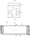
- FIG. 6 is a diagram for illustrating a process of injecting a thermally conductive adhesive into the battery module of FIG. 1 .
- a worker or the like when manufacturing the battery module 10, first, a worker or the like may accommodate the battery cell assembly 100 in the module case 200. Then, the worker may arrange the module case 200 horizontally before injecting the thermally conductive adhesive TR.
- the worker or the like may insert the injection nozzles into the plurality of injection holes 300 provided in the middle region of the bottom portion 210 of the module case 200 to coat the thermally conductive adhesive TR to the inside of the module case 200 and then inject the thermally conductive adhesive TR into the module case 200.
- the plurality of injection holes 300 are located in the middle region of the bottom portion 210 of the module case 200.
- the thermally conductive adhesive TR since the module case 200 is positioned horizontally and then the thermally conductive adhesive TR is injected in a direction perpendicular to the ground, the thermally conductive adhesive TR may be uniformly distributed inside the module case 200.
- FIG. 7 is a diagram for illustrating a battery module according to another embodiment of the present disclosure
- FIG. 8 is a diagram for illustrating a process of injecting a thermally conductive adhesive into the battery module of FIG. 7 .
- the battery module 20 according to this embodiment is substantially identical or similar to the battery module 10 of the former embodiment, and thus the identical or similar features will not described in detail but different features will be described in detail.
- the battery module 20 may include a battery cell assembly 100, a module case 200 and an injection hole 400.
- the battery cell assembly 100 and the module case 200 are substantially identical or similar to those of the former embodiment and thus will be described in detail here.
- the injection holes 400 may be provided in plural.
- the plurality of injection holes 400 may be provided at one side rim region of the bottom portion 210 of the module case 200.
- a worker or the like may accommodate the battery cell assembly 100 in the module case 200, similar to the former embodiment. Then, the worker or the like may arrange the module case 200 vertically before injecting the thermally conductive adhesive TR.
- the worker or the like may insert the injection nozzles into the plurality of injection holes 400 provided at one side rim region of the bottom portion 210 of the module case 200, specifically at an upper rim region thereof, to coat the thermally conductive adhesive TR to the inside of the module case 200, and then inject the thermally conductive adhesive TR into the module case 200.
- the plurality of injection holes 400 are located in one side rim region of the bottom portion 210 of the module case 200.
- the thermally conductive adhesive TR since the module case 200 is positioned vertically and then the thermally conductive adhesive TR is injected in a direction horizontal to the ground, the thermally conductive adhesive TR may be uniformly distributed inside the module case 200.
- the thermally conductive adhesive TR since the thermally conductive adhesive TR is applied in a vertically descending manner by gravity, the thermally conductive adhesive TR may be uniformly distributed to the lower side of the module case 200 in a natural way.
- FIG. 9 is a diagram for illustrating a battery pack according to an embodiment of the present disclosure.
- a battery pack 1 may include at least one battery module 10, 20 according to the former embodiment and a pack case 50 for packaging the at least one battery module 10, 20.
- the battery pack 1 may be provided to a vehicle as a fuel source of the vehicle.
- the battery pack 1 may be provided to an electric vehicle, a hybrid vehicle, and various other-type vehicles capable of using the battery pack 1 as a fuel source.
- the battery pack 1 may be provided in other devices, instruments or facilities such as an energy storage system using a secondary battery, in addition to the vehicle.
- the battery pack 1 of this embodiment and devices, instruments or facilities such as a vehicle, which have the battery pack 1 include the battery module 10, 20 as described above, and thus it is possible to implement a battery pack 1 having all the advantages of the battery module 10 described above, or devices, instruments, facilities or the like such as a vehicle, which have the battery pack 1.
Abstract
Description
- The present disclosure relates to a method for manufacturing a battery module.
- The present application claims priority to Korean Patent Application No.
10-2017-0008279 filed on January 17, 2017 - Secondary batteries which are highly applicable to various products and exhibit superior electrical properties such as high energy density, etc. are commonly used not only in portable devices but also in electric vehicles (EVs) or hybrid electric vehicles (HEVs) driven by electrical power sources. The secondary battery is drawing attentions as a new energy source for enhancing environment friendliness and energy efficiency in that the use of fossil fuels can be reduced greatly and no byproduct is generated during energy consumption.
- Secondary batteries widely used at the preset include lithium ion batteries, lithium polymer batteries, nickel cadmium batteries, nickel hydrogen batteries, nickel zinc batteries and the like. An operating voltage of the unit secondary battery cell, namely a unit battery cell, is about 2.5V to 4.5V. Therefore, if a higher output voltage is required, a plurality of battery cells may be connected in series to configure a battery pack. In addition, depending on the charge/discharge capacity required for the battery pack, a plurality of battery cells may be connected in parallel to configure a battery pack. Thus, the number of battery cells included in the battery pack may be variously set according to the required output voltage or the demanded charge/discharge capacity.
- Meanwhile, when a plurality of battery cells are connected in series or in parallel to configure a battery pack, it is common to configure a battery module composed of at least one battery cell first, and then configure a battery pack by using at least one battery module and adding other components.
- In the case of the conventional battery module, the technology for efficiently cooling the heat generated at the battery cells is becoming more and more important as the demanded battery capacity is increasing.
- For the efficient cooling, in the conventional battery module, a thermally conductive adhesive is applied to the inside of a module case to stably fix a battery cell assembly including at least one battery cell in the module case and to improve thermal conductivity.
- However, in the conventional battery module, when an injection hole for injecting the thermally conductive adhesive into the module case is formed, the battery cell assembly in the module case may be damaged due to burr or the like, or an injection nozzle for injecting the thermally conductive adhesive may not be accurately inserted into the injection hole, or the thermally conductive adhesive may leak out of the module case.
- The present disclosure is designed to solve the problems of the related art, and therefore the present disclosure is directed to providing a method for manufacturing a battery module, which may enhance the thermally conductive adhesive injecting efficiency and prevent a battery cell assembly from being damaged, in a battery module that is cooled using the thermally conductive adhesive.
- In one aspect of the present disclosure, there is provided a method for manufacturing a battery module, comprising: accommodating a battery cell assembly having at least one battery cell in a module case; and injecting a thermally conductive adhesive through at least one injection hole provided in a bottom portion of the module case so that the module case is coated with the thermally conductive adhesive.
- The method for manufacturing a battery module may further include arranging the module case in a horizontal direction, before the thermally conductive adhesive is injected.
- The at least one injection hole may be provided at a middle region of the bottom portion of the module case.
- The method for manufacturing a battery module may further include arranging the module case in a vertical direction, before the thermally conductive adhesive is injected.
- The at least one injection hole may be provided at one side rim region of the bottom portion the module case.
- The injection hole may be provided in plural, and the plurality of injection holes may be spaced apart from each other by a predetermined distance at the bottom portion of the module case.
- Convex portions and concave portions may be formed alternately at an inner surface of the bottom portion of the module case, and the plurality of injection holes may be provided in the convex portions.
- The convex portions and the concave portions may have a rounded shape.
- The plurality of injection holes may have an inclined chamfer portion at one side thereof.
- The plurality of injection holes may have different spacing distances in an outer direction from the center of the bottom portion of the module case.
- According to various embodiments as above, it is possible to provide a method for manufacturing a battery module, which may enhance the thermally conductive adhesive injecting efficiency and prevent a battery cell assembly from being damaged, in a battery module that is cooled using the thermally conductive adhesive.
- The accompanying drawings illustrate a preferred embodiment of the present disclosure and together with the foregoing disclosure, serve to provide further understanding of the technical features of the present disclosure, and thus, the present disclosure is not construed as being limited to the drawing.
-
FIG. 1 is a diagram for illustrating a battery module according to an embodiment of the present disclosure. -
FIG. 2 is a bottom perspective view showing the battery module ofFIG. 1 . -
FIG. 3 is an enlarged view showing a main portion of the battery module ofFIG. 2 . -
FIG. 4 is a cross-sectioned view showing a main portion of the battery module ofFIG. 1 . -
FIG. 5 is an enlarged view showing a portion C ofFIG. 4 . -
FIG. 6 is a diagram for illustrating a process of injecting a thermally conductive adhesive into the battery module ofFIG. 1 . -
FIG. 7 is a diagram for illustrating a battery module according to another embodiment of the present disclosure. -
FIG. 8 is a diagram for illustrating a process of injecting a thermally conductive adhesive into the battery module ofFIG. 7 . -
FIG. 9 is a diagram for illustrating a battery pack according to an embodiment of the present disclosure. - The present disclosure will become more apparent by describing in detail the embodiments of the present disclosure with reference to the accompanying drawings. It should be understood that the embodiments disclosed herein are illustrative only for better understanding of the present disclosure, and that the present disclosure may be modified in various ways. In addition, for ease understanding of the present disclosure, the accompanying drawings are not drawn to real scale, but the dimensions of some components may be exaggerated.
-
FIG. 1 is a diagram for illustrating a battery module according to an embodiment of the present disclosure,FIG. 2 is a bottom perspective view showing the battery module ofFIG. 1 ,FIG. 3 is an enlarged view showing a main portion of the battery module ofFIG. 2 ,FIG. 4 is a cross-sectioned view showing a main portion of the battery module ofFIG. 1 , andFIG. 5 is an enlarged view showing a portion C ofFIG. 4 . - Referring to
FIGS. 1 to 5 , abattery module 10 may include abattery cell assembly 100, amodule case 200 and aninjection hole 300. - The
battery cell assembly 100 includes at least one battery cell. Hereinafter, this embodiment will be described based on the case where a plurality of battery cells are stacked to be electrically connected to each other. Here, each battery cell may be a pouch type secondary battery. - The
module case 200 is used for accommodating thebattery cell assembly 100 and may have an accommodation space formed therein. A thermally conductive adhesive TR, explained later, may be coated on an inside of themodule case 200, specifically on an upper side of an inner surface of thebottom portion 210 of themodule case 200. - Here, convex
portions 212 andconcave portions 216 may be alternately formed at one side of the inner surface of thebottom portion 210 of themodule case 200. Specifically, theconvex portions 212 and theconcave portions 216 may be provided at positions corresponding to locations where a plurality ofinjection holes 300, explained later, are formed. - The
convex portions 212 and theconcave portions 216 may be arranged to face thebattery cell assembly 100 in themodule case 200 and may have a rounded shape to prevent thebattery cell assembly 100 from being damaged. - The
injection hole 300 is provided in thebottom portion 210 of themodule case 200 and may allow the thermally conductive adhesive TR to be injected into themodule case 200. The thermally conductive adhesive TR is a cooling adhesive with thermal conductivity and may be a thermal resin. - The
injection hole 300 may be provided in plural, and the plurality ofinjection holes 300 may be spaced apart from each other by a predetermined distance at thebottom portion 210 of themodule case 200. In particular, the plurality ofinjection holes 300 may be provided in a middle region of thebottom portion 210 of themodule case 200. - The plurality of
injection holes 300 may be provided in a number such that the thermally conductive adhesive TR may be smoothly coated to the inside of themodule case 200. For example, the number of theinjection holes 300 may be three to five. - The plurality of
injection holes 300 may have spacing distances that varies in an outer direction from the center of thebottom portion 210 of themodule case 200. Specifically, a spacing distance A between theinjection hole 300 disposed at the center of thebottom portion 210 of themodule case 200 and theinjection holes 300 disposed at both sides thereof and a spacing distance B between theinjection holes 300 disposed at the outer side of the bottom portion of themodule case 200 and theinjection holes 300 disposed at a side thereof may be different from each other. This is for uniform coating of the thermally conductive adhesive TR to the inside of themodule case 200, and, for example, the spacing distance B at an outer side may be greater than the spacing distance A at an inner side. - The plurality of
injection holes 300 may be provided at theconvex portions 212. Accordingly, the plurality ofinjection holes 300 may be formed in a thickest region of thebottom portion 210 of themodule case 200. Thus, in this embodiment, it is possible to minimize the stiffness variation of themodule case 200 due to the injection holes 300. - An
inclined chamfer portion 310 may be provided at oneend 310 of the plurality of injection holes 300, specifically at anend 310 exposed to the outside of thebottom portion 210 of themodule case 200. Thechamfer portion 310 guides an injection nozzle for injecting the thermally conductive adhesive TR to be positioned in the injection holes 300 and increases the contact area with the injection nozzle, thereby improving the sealing force when the injection nozzle is mounted. - The
other end 330 of the plurality of injection holes 300, specifically anend 330 exposed to the inside of thebottom portion 210 of themodule case 200, may have a rounded shape. Accordingly, in this embodiment, when the thermally conductive adhesive TR is injected, it is possible to minimize the impact applied to thebattery cell assembly 100 and themodule case 200 by the injected thermally conductive adhesive TR. - Hereinafter, a method for manufacturing the
battery module 10 according to this embodiment will be described in detail. -
FIG. 6 is a diagram for illustrating a process of injecting a thermally conductive adhesive into the battery module ofFIG. 1 . - Referring to
FIG. 6 , when manufacturing thebattery module 10, first, a worker or the like may accommodate thebattery cell assembly 100 in themodule case 200. Then, the worker may arrange themodule case 200 horizontally before injecting the thermally conductive adhesive TR. - After that, the worker or the like may insert the injection nozzles into the plurality of injection holes 300 provided in the middle region of the
bottom portion 210 of themodule case 200 to coat the thermally conductive adhesive TR to the inside of themodule case 200 and then inject the thermally conductive adhesive TR into themodule case 200. - In this embodiment, the plurality of injection holes 300 are located in the middle region of the
bottom portion 210 of themodule case 200. Here, since themodule case 200 is positioned horizontally and then the thermally conductive adhesive TR is injected in a direction perpendicular to the ground, the thermally conductive adhesive TR may be uniformly distributed inside themodule case 200. -
FIG. 7 is a diagram for illustrating a battery module according to another embodiment of the present disclosure, andFIG. 8 is a diagram for illustrating a process of injecting a thermally conductive adhesive into the battery module ofFIG. 7 . - The
battery module 20 according to this embodiment is substantially identical or similar to thebattery module 10 of the former embodiment, and thus the identical or similar features will not described in detail but different features will be described in detail. - Referring to
FIGS. 7 and8 , thebattery module 20 may include abattery cell assembly 100, amodule case 200 and aninjection hole 400. - The
battery cell assembly 100 and themodule case 200 are substantially identical or similar to those of the former embodiment and thus will be described in detail here. - The injection holes 400 may be provided in plural. The plurality of injection holes 400 may be provided at one side rim region of the
bottom portion 210 of themodule case 200. - Hereinafter, a method for manufacturing the
battery module 20 according to this embodiment will be described in detail. - When manufacturing the
battery module 20, a worker or the like may accommodate thebattery cell assembly 100 in themodule case 200, similar to the former embodiment. Then, the worker or the like may arrange themodule case 200 vertically before injecting the thermally conductive adhesive TR. - After that, the worker or the like may insert the injection nozzles into the plurality of injection holes 400 provided at one side rim region of the
bottom portion 210 of themodule case 200, specifically at an upper rim region thereof, to coat the thermally conductive adhesive TR to the inside of themodule case 200, and then inject the thermally conductive adhesive TR into themodule case 200. - In this embodiment, the plurality of injection holes 400 are located in one side rim region of the
bottom portion 210 of themodule case 200. Here, since themodule case 200 is positioned vertically and then the thermally conductive adhesive TR is injected in a direction horizontal to the ground, the thermally conductive adhesive TR may be uniformly distributed inside themodule case 200. In other words, in this embodiment, since the thermally conductive adhesive TR is applied in a vertically descending manner by gravity, the thermally conductive adhesive TR may be uniformly distributed to the lower side of themodule case 200 in a natural way. - As described above, in this embodiment, in the
battery module battery cell assembly 100 and themodule case 200 from being damaged. -
FIG. 9 is a diagram for illustrating a battery pack according to an embodiment of the present disclosure. - Referring to
FIG. 9 , abattery pack 1 may include at least onebattery module pack case 50 for packaging the at least onebattery module - The
battery pack 1 may be provided to a vehicle as a fuel source of the vehicle. As an example, thebattery pack 1 may be provided to an electric vehicle, a hybrid vehicle, and various other-type vehicles capable of using thebattery pack 1 as a fuel source. In addition, thebattery pack 1 may be provided in other devices, instruments or facilities such as an energy storage system using a secondary battery, in addition to the vehicle. - As described above, the
battery pack 1 of this embodiment and devices, instruments or facilities such as a vehicle, which have thebattery pack 1, include thebattery module battery pack 1 having all the advantages of thebattery module 10 described above, or devices, instruments, facilities or the like such as a vehicle, which have thebattery pack 1. - While the embodiments of the present disclosure have been shown and described, it should be understood that the present disclosure is not limited to the specific embodiments described, and that various changes and modifications can be made within the scope of the present disclosure by those skilled in the art, and these modifications should not be understood individually from the technical ideas and views of the present disclosure.
Claims (10)
- A method for manufacturing a battery module, comprising:accommodating a battery cell assembly having at least one battery cell in a module case; andinjecting a thermally conductive adhesive through at least one injection hole provided in a bottom portion of the module case so that the module case is coated with the thermally conductive adhesive.
- The method for manufacturing a battery module according to claim 1, before the thermally conductive adhesive is injected, further comprising:
arranging the module case in a horizontal direction. - The method for manufacturing a battery module according to claim 2,
wherein the at least one injection hole is provided at a middle region of the bottom portion of the module case. - The method for manufacturing a battery module according to claim 1, before the thermally conductive adhesive is injected, further comprising:
arranging the module case in a vertical direction. - The method for manufacturing a battery module according to claim 4,
wherein the at least one injection hole is provided at one side rim region of the bottom portion the module case. - The method for manufacturing a battery module according to claim 1,
wherein the injection hole is provided in plural, and the plurality of injection holes are spaced apart from each other by a predetermined distance at the bottom portion of the module case. - The method for manufacturing a battery module according to claim 6,
wherein convex portions and concave portions are formed alternately at an inner surface of the bottom portion of the module case, and
wherein the plurality of injection holes are provided in the convex portions. - The method for manufacturing a battery module according to claim 7,
wherein the convex portions and the concave portions have a rounded shape. - The method for manufacturing a battery module according to claim 6,
wherein the plurality of injection holes have an inclined chamfer portion at one side thereof. - The method for manufacturing a battery module according to claim 6,
wherein the plurality of injection holes have different spacing distances in an outer direction from the center of the bottom portion of the module case.
Priority Applications (1)
| Application Number | Priority Date | Filing Date | Title |
|---|---|---|---|
| PL17892284T PL3444889T3 (en) | 2017-01-17 | 2017-12-12 | Method for manufacturing battery module |
Applications Claiming Priority (2)
| Application Number | Priority Date | Filing Date | Title |
|---|---|---|---|
| KR1020170008279A KR102201348B1 (en) | 2017-01-17 | 2017-01-17 | Fabricating method of battery module |
| PCT/KR2017/014584 WO2018135757A1 (en) | 2017-01-17 | 2017-12-12 | Method for producing battery module |
Publications (3)
| Publication Number | Publication Date |
|---|---|
| EP3444889A1 true EP3444889A1 (en) | 2019-02-20 |
| EP3444889A4 EP3444889A4 (en) | 2019-07-31 |
| EP3444889B1 EP3444889B1 (en) | 2020-06-24 |
Family
ID=62909254
Family Applications (1)
| Application Number | Title | Priority Date | Filing Date |
|---|---|---|---|
| EP17892284.5A Active EP3444889B1 (en) | 2017-01-17 | 2017-12-12 | Method for manufacturing battery module |
Country Status (7)
| Country | Link |
|---|---|
| US (2) | US10992000B2 (en) |
| EP (1) | EP3444889B1 (en) |
| JP (1) | JP6695445B2 (en) |
| KR (1) | KR102201348B1 (en) |
| CN (1) | CN109155449B (en) |
| PL (1) | PL3444889T3 (en) |
| WO (1) | WO2018135757A1 (en) |
Cited By (8)
| Publication number | Priority date | Publication date | Assignee | Title |
|---|---|---|---|---|
| DE102018219732A1 (en) * | 2018-11-16 | 2020-05-20 | Audi Ag | Battery housing for receiving a battery module, battery module arrangement, motor vehicle and method for introducing a heat-conducting element into a battery housing |
| DE102018220626A1 (en) * | 2018-11-29 | 2020-06-04 | Audi Ag | Method and manufacturing device for manufacturing a battery and motor vehicle with a corresponding battery |
| DE102018221988A1 (en) * | 2018-12-17 | 2020-06-18 | Audi Ag | Battery housing for receiving a battery module, battery module arrangement, motor vehicle and method for introducing a heat-conducting element into a battery housing |
| DE102019215775A1 (en) * | 2019-10-14 | 2021-04-15 | Robert Bosch Gmbh | Battery module with at least one single cell and a cell holder for receiving the at least one single cell and a method for producing such a battery module |
| DE102019130730A1 (en) * | 2019-11-14 | 2021-05-20 | Audi Ag | Traction battery for an electrically powered vehicle |
| EP3843174A4 (en) * | 2019-06-12 | 2021-12-15 | LG Chem, Ltd. | Battery module, method for preparing same, and battery pack including same |
| DE102021104939A1 (en) | 2021-03-02 | 2022-09-08 | Audi Aktiengesellschaft | Method for introducing a heat-conducting compound into a battery module and injection arrangement |
| US11489216B2 (en) | 2018-12-20 | 2022-11-01 | Audi Ag | Method for providing a battery arrangement for a motor vehicle, and motor vehicle |
Families Citing this family (47)
| Publication number | Priority date | Publication date | Assignee | Title |
|---|---|---|---|---|
| USD888667S1 (en) * | 2017-09-29 | 2020-06-30 | Premier Technologies Ltd. | Batteryless jump starter |
| JP1615339S (en) * | 2017-10-20 | 2018-10-09 | ||
| USD867284S1 (en) * | 2018-01-17 | 2019-11-19 | Ke Teng Lai | Power inverter |
| USD864864S1 (en) * | 2018-01-30 | 2019-10-29 | Guangdong Bestek E-Commerce Co., Ltd. | Inverter |
| USD879714S1 (en) * | 2018-02-02 | 2020-03-31 | Cheng Uei Precision Industry Co., Ltd. | Adapter |
| USD883927S1 (en) * | 2018-03-08 | 2020-05-12 | Schneider Electric It Corporation | Uninterruptible power supply |
| USD866462S1 (en) * | 2018-03-12 | 2019-11-12 | I/O Interconnect, Ltd. | Power bank |
| TWD195351S (en) * | 2018-03-12 | 2019-01-11 | 光陽工業股份有限公司 | Transformer (2) |
| USD877075S1 (en) * | 2018-03-23 | 2020-03-03 | Gopod Group Ltd. | Wireless charging hub |
| JP1615484S (en) * | 2018-03-26 | 2018-10-09 | ||
| USD894831S1 (en) * | 2018-03-29 | 2020-09-01 | Robert Bosch Gmbh | Electric propulsion apparatus |
| USD884631S1 (en) * | 2018-04-16 | 2020-05-19 | Furrion Property Holding Limited | Electrical device mount |
| USD896752S1 (en) * | 2018-05-21 | 2020-09-22 | Shenzhen Segre Electronic Co., Ltd | Power converter |
| USD897289S1 (en) * | 2018-06-21 | 2020-09-29 | Logicdata Electronic & Software Entwicklungs Gmbh | Power supply unit |
| USD875681S1 (en) * | 2018-07-05 | 2020-02-18 | Guangdong Bestek E-Commerce Co., Ltd. | Inverter |
| USD887356S1 (en) * | 2018-07-09 | 2020-06-16 | Guangzhou City Poojin Electronic Technology Co., Ltd | Power inverter with LCD |
| USD883207S1 (en) * | 2018-07-10 | 2020-05-05 | Sumitomo Heavy Industries, Ltd. | Frequency converter |
| KR102324868B1 (en) * | 2018-07-27 | 2021-11-09 | 주식회사 엘지에너지솔루션 | Battery module, battery pack comprising the battery module and vehicle comprising the battery pack |
| USD876350S1 (en) * | 2018-08-13 | 2020-02-25 | Dongguan Mauten Electronic Technology Co., Ltd. | High-power inverter |
| USD875044S1 (en) * | 2018-09-01 | 2020-02-11 | Timotion Technology Co., Ltd. | Power supply |
| KR102389911B1 (en) | 2018-09-17 | 2022-04-21 | 주식회사 엘지에너지솔루션 | Battery Module Having Module Housing |
| USD875045S1 (en) * | 2018-09-25 | 2020-02-11 | Guangdong Bestek E-Commerce Co., Ltd. | Inverter |
| USD894830S1 (en) * | 2018-10-01 | 2020-09-01 | Robert Bosch Gmbh | Electric propulsion apparatus |
| USD895546S1 (en) * | 2018-10-01 | 2020-09-08 | Robert Bosch Gmbh | Electric propulsion apparatus |
| USD891369S1 (en) * | 2018-10-15 | 2020-07-28 | Jiangxi Baiying High-Tech Holdings Co., LTD. | Inverter |
| USD931807S1 (en) * | 2018-10-15 | 2021-09-28 | Jingxi Baiying High-Tech Holdings Co., LTD. | Inverter |
| USD885340S1 (en) * | 2018-11-08 | 2020-05-26 | Ling To Shum | Power inverter |
| JP7086420B2 (en) * | 2019-02-13 | 2022-06-20 | エルジー エナジー ソリューション リミテッド | Battery module, its manufacturing method and battery pack containing the battery module |
| USD887979S1 (en) * | 2019-04-01 | 2020-06-23 | Guangdong Gopod Group Holding Co., Ltd. | AC transformer for multiple portable electronic devices |
| USD904300S1 (en) * | 2019-04-25 | 2020-12-08 | Huizhou Zhongbang Electric Co., Ltd. | Power adapter |
| USD896754S1 (en) * | 2019-04-29 | 2020-09-22 | Bushnell Inc. | Trap battery power adapter |
| USD895547S1 (en) * | 2019-05-06 | 2020-09-08 | Delta Electronics, Inc. | Light emitting diode driver |
| DE102019208806B3 (en) * | 2019-06-18 | 2020-08-27 | Audi Ag | Method for injecting a filling compound, in particular a heat-conducting paste, into a battery module device, injection system and motor vehicle with a battery module device |
| USD895548S1 (en) * | 2019-06-21 | 2020-09-08 | Huizhou Zhongbang Electric Co., Ltd. | Power adapter |
| USD904301S1 (en) * | 2019-06-24 | 2020-12-08 | Comcast Cable Communications, Llc | Power supply |
| DE102019210437A1 (en) * | 2019-07-15 | 2021-01-21 | Audi Ag | Device and method for distributing a cavity filling compound in a battery |
| KR20210040720A (en) * | 2019-10-04 | 2021-04-14 | 주식회사 엘지화학 | Battery module, battery pack comprising the battery module and vehicle comprising the battery pack |
| KR20210040719A (en) * | 2019-10-04 | 2021-04-14 | 주식회사 엘지화학 | Battery module, battery pack comprising the battery module and vehicle comprising the battery pack |
| DE102019130385A1 (en) * | 2019-11-11 | 2021-05-12 | Audi Ag | Traction battery and method for assembling such a traction battery |
| KR20210143565A (en) * | 2020-05-20 | 2021-11-29 | 주식회사 엘지에너지솔루션 | System and method for ultrasonic inspection |
| KR20210157005A (en) * | 2020-06-19 | 2021-12-28 | 주식회사 엘지에너지솔루션 | Battery module and battery pack including the same |
| USD972567S1 (en) * | 2020-08-14 | 2022-12-13 | Robert Bosch Gmbh | Electronic control device |
| US20220173452A1 (en) * | 2020-12-02 | 2022-06-02 | GM Global Technology Operations LLC | Method of injecting thermal adhesive in high-voltage batteries |
| DE102021118643A1 (en) | 2021-07-20 | 2023-01-26 | Audi Aktiengesellschaft | Method for introducing a heat-conducting compound between a battery module and a housing base, battery and motor vehicle |
| DE102021118644A1 (en) | 2021-07-20 | 2023-01-26 | Audi Aktiengesellschaft | Method for introducing a heat-conducting compound between a battery module and a housing base, battery and motor vehicle |
| US20230060247A1 (en) * | 2021-08-25 | 2023-03-02 | GM Global Technology Operations LLC | Battery including thermally conductive filler material with thermal runaway containment function |
| DE102021127842A1 (en) * | 2021-10-26 | 2023-04-27 | Dr. Ing. H.C. F. Porsche Aktiengesellschaft | Method and device for cell fold bonding when filling a battery module with heat-conducting paste |
Family Cites Families (27)
| Publication number | Priority date | Publication date | Assignee | Title |
|---|---|---|---|---|
| JPH06275246A (en) | 1993-03-24 | 1994-09-30 | Shin Kobe Electric Mach Co Ltd | Manufacture of mono-block battery jar |
| JP4118014B2 (en) | 2000-10-31 | 2008-07-16 | 三洋電機株式会社 | Power supply |
| DE60307750T2 (en) | 2002-05-08 | 2006-12-14 | Nissan Motor Co., Ltd., Yokohama | Secondary cell module and method for its production |
| JP3940342B2 (en) * | 2002-09-13 | 2007-07-04 | 日産自動車株式会社 | Secondary battery module and manufacturing method thereof |
| KR100770115B1 (en) * | 2005-12-29 | 2007-10-24 | 삼성에스디아이 주식회사 | Battery Pack |
| KR100776767B1 (en) | 2006-05-17 | 2007-11-16 | 현대에너셀 주식회사 | Aseismatic structure case of rechargeable battery |
| JP4434237B2 (en) | 2007-06-20 | 2010-03-17 | トヨタ自動車株式会社 | Power storage device for vehicle and vehicle |
| WO2010098067A1 (en) | 2009-02-24 | 2010-09-02 | パナソニック株式会社 | Battery module and battery module assembly using same |
| WO2012153752A1 (en) | 2011-05-10 | 2012-11-15 | 新神戸電機株式会社 | Wound secondary battery |
| KR20130046999A (en) * | 2011-10-31 | 2013-05-08 | 에스케이이노베이션 주식회사 | Battery cell and battery module using the same |
| KR101866345B1 (en) | 2011-12-02 | 2018-06-12 | 에스케이이노베이션 주식회사 | Battery Module |
| JP2014086342A (en) * | 2012-10-25 | 2014-05-12 | Sanyo Electric Co Ltd | Battery pack and manufacturing method therefor |
| KR101636378B1 (en) * | 2013-08-28 | 2016-07-05 | 주식회사 엘지화학 | Module Housing for Unit Module Having Heat Radiation Structure and Battery Module Comprising the Same |
| KR20150049598A (en) | 2013-10-30 | 2015-05-08 | 주식회사 엘지화학 | Secondary battery and Electrolyte injection system comprising the same |
| JP6107606B2 (en) | 2013-11-05 | 2017-04-05 | 株式会社豊田自動織機 | Method for manufacturing power storage device |
| KR102378426B1 (en) | 2014-07-28 | 2022-03-24 | 삼성에스디아이 주식회사 | Battery module |
| KR101676407B1 (en) | 2014-09-22 | 2016-11-29 | 주식회사 엘지화학 | Test method for thermal pad and method of fabricating battery module using the same |
| JP6137140B2 (en) | 2014-11-25 | 2017-05-31 | トヨタ自動車株式会社 | Battery pack and manufacturing method thereof |
| JP6102896B2 (en) | 2014-11-26 | 2017-03-29 | トヨタ自動車株式会社 | Assembled battery |
| KR101831816B1 (en) | 2015-02-06 | 2018-02-23 | 주식회사 엘지화학 | Cell Module Improved Weldability |
| JP6681911B2 (en) * | 2015-02-27 | 2020-04-15 | エルジー・ケム・リミテッド | Battery module |
| KR101792751B1 (en) | 2015-05-13 | 2017-10-31 | 주식회사 엘지화학 | Battery module |
| JP2017079184A (en) * | 2015-10-22 | 2017-04-27 | トヨタ自動車株式会社 | Method for manufacturing assembled battery |
| JP6315007B2 (en) | 2016-02-23 | 2018-04-25 | トヨタ自動車株式会社 | Battery module |
| KR102082906B1 (en) * | 2016-10-10 | 2020-02-28 | 주식회사 엘지화학 | Battery module assembly |
| KR102207881B1 (en) * | 2017-01-17 | 2021-01-25 | 주식회사 엘지화학 | Battery module, battery pack comprising the battery module and vehicle comprising the battery pack |
| US11127995B2 (en) * | 2018-09-28 | 2021-09-21 | Nio Usa, Inc. | Lightweight thermal adsorption structure for lithium-ion module |
-
2017
- 2017-01-17 KR KR1020170008279A patent/KR102201348B1/en active IP Right Grant
- 2017-12-12 EP EP17892284.5A patent/EP3444889B1/en active Active
- 2017-12-12 PL PL17892284T patent/PL3444889T3/en unknown
- 2017-12-12 WO PCT/KR2017/014584 patent/WO2018135757A1/en active Application Filing
- 2017-12-12 US US16/095,814 patent/US10992000B2/en active Active
- 2017-12-12 CN CN201780030033.2A patent/CN109155449B/en active Active
- 2017-12-12 JP JP2018557831A patent/JP6695445B2/en active Active
-
2021
- 2021-01-26 US US17/158,320 patent/US11476519B2/en active Active
Cited By (10)
| Publication number | Priority date | Publication date | Assignee | Title |
|---|---|---|---|---|
| DE102018219732A1 (en) * | 2018-11-16 | 2020-05-20 | Audi Ag | Battery housing for receiving a battery module, battery module arrangement, motor vehicle and method for introducing a heat-conducting element into a battery housing |
| DE102018220626A1 (en) * | 2018-11-29 | 2020-06-04 | Audi Ag | Method and manufacturing device for manufacturing a battery and motor vehicle with a corresponding battery |
| US11189856B2 (en) | 2018-11-29 | 2021-11-30 | Audi Ag | Method and production equipment for producing a battery and motor vehicle with a corresponding battery |
| DE102018221988A1 (en) * | 2018-12-17 | 2020-06-18 | Audi Ag | Battery housing for receiving a battery module, battery module arrangement, motor vehicle and method for introducing a heat-conducting element into a battery housing |
| US11316229B2 (en) | 2018-12-17 | 2022-04-26 | Audi Ag | Battery housing to hold a battery module, battery module arrangement, motor vehicle and method for incorporating a thermally conductive element in a battery housing |
| US11489216B2 (en) | 2018-12-20 | 2022-11-01 | Audi Ag | Method for providing a battery arrangement for a motor vehicle, and motor vehicle |
| EP3843174A4 (en) * | 2019-06-12 | 2021-12-15 | LG Chem, Ltd. | Battery module, method for preparing same, and battery pack including same |
| DE102019215775A1 (en) * | 2019-10-14 | 2021-04-15 | Robert Bosch Gmbh | Battery module with at least one single cell and a cell holder for receiving the at least one single cell and a method for producing such a battery module |
| DE102019130730A1 (en) * | 2019-11-14 | 2021-05-20 | Audi Ag | Traction battery for an electrically powered vehicle |
| DE102021104939A1 (en) | 2021-03-02 | 2022-09-08 | Audi Aktiengesellschaft | Method for introducing a heat-conducting compound into a battery module and injection arrangement |
Also Published As
| Publication number | Publication date |
|---|---|
| US10992000B2 (en) | 2021-04-27 |
| CN109155449A (en) | 2019-01-04 |
| EP3444889B1 (en) | 2020-06-24 |
| US11476519B2 (en) | 2022-10-18 |
| JP6695445B2 (en) | 2020-05-20 |
| CN109155449B (en) | 2022-01-11 |
| PL3444889T3 (en) | 2020-11-16 |
| US20190131678A1 (en) | 2019-05-02 |
| WO2018135757A1 (en) | 2018-07-26 |
| US20210151820A1 (en) | 2021-05-20 |
| KR102201348B1 (en) | 2021-01-08 |
| EP3444889A4 (en) | 2019-07-31 |
| JP2019515461A (en) | 2019-06-06 |
| KR20180084540A (en) | 2018-07-25 |
Similar Documents
| Publication | Publication Date | Title |
|---|---|---|
| US11476519B2 (en) | Method for manufacturing battery module | |
| US11961983B2 (en) | Battery module, battery pack including battery module, and vehicle including battery pack | |
| EP3675274A1 (en) | Battery module, battery pack including battery module, and vehicle including battery pack | |
| EP3291360B1 (en) | Battery pack and vehicle including such battery pack | |
| EP3474345A1 (en) | Battery module, battery pack including the battery module, and automobile including the battery pack | |
| EP3696905B1 (en) | Battery module and battery pack comprising same battery module | |
| US10854936B2 (en) | Battery module, battery pack including battery module, and vehicle including battery pack | |
| US11456500B2 (en) | Battery module, battery pack including battery module, and vehicle including battery pack | |
| EP4019179B1 (en) | Battery module, and battery pack and vehicle including battery module | |
| US20220336881A1 (en) | Battery Module, Battery Pack Comprising Battery Module, and Vehicle Comprising Battery Pack | |
| EP4002554A1 (en) | Battery module, battery pack including battery module, and vehicle including battery pack | |
| US20230299405A1 (en) | Battery module, and battery pack and vehicle that include same | |
| KR102082902B1 (en) | Battery module, battery pack comprising the battery module and vehicle comprising the battery pack |
Legal Events
| Date | Code | Title | Description |
|---|---|---|---|
| STAA | Information on the status of an ep patent application or granted ep patent |
Free format text: STATUS: THE INTERNATIONAL PUBLICATION HAS BEEN MADE |
|
| PUAI | Public reference made under article 153(3) epc to a published international application that has entered the european phase |
Free format text: ORIGINAL CODE: 0009012 |
|
| STAA | Information on the status of an ep patent application or granted ep patent |
Free format text: STATUS: REQUEST FOR EXAMINATION WAS MADE |
|
| 17P | Request for examination filed |
Effective date: 20181114 |
|
| AK | Designated contracting states |
Kind code of ref document: A1 Designated state(s): AL AT BE BG CH CY CZ DE DK EE ES FI FR GB GR HR HU IE IS IT LI LT LU LV MC MK MT NL NO PL PT RO RS SE SI SK SM TR |
|
| AX | Request for extension of the european patent |
Extension state: BA ME |
|
| REG | Reference to a national code |
Ref country code: DE Ref legal event code: R079 Ref document number: 602017018852 Country of ref document: DE Free format text: PREVIOUS MAIN CLASS: H01M0010656000 Ipc: H01M0002100000 |
|
| A4 | Supplementary search report drawn up and despatched |
Effective date: 20190701 |
|
| RIC1 | Information provided on ipc code assigned before grant |
Ipc: H01M 2/10 20060101AFI20190625BHEP Ipc: H01M 10/613 20140101ALI20190625BHEP Ipc: H01M 10/656 20140101ALI20190625BHEP Ipc: H01M 10/6567 20140101ALI20190625BHEP |
|
| GRAP | Despatch of communication of intention to grant a patent |
Free format text: ORIGINAL CODE: EPIDOSNIGR1 |
|
| STAA | Information on the status of an ep patent application or granted ep patent |
Free format text: STATUS: GRANT OF PATENT IS INTENDED |
|
| DAV | Request for validation of the european patent (deleted) | ||
| DAX | Request for extension of the european patent (deleted) | ||
| INTG | Intention to grant announced |
Effective date: 20191104 |
|
| GRAS | Grant fee paid |
Free format text: ORIGINAL CODE: EPIDOSNIGR3 |
|
| GRAA | (expected) grant |
Free format text: ORIGINAL CODE: 0009210 |
|
| STAA | Information on the status of an ep patent application or granted ep patent |
Free format text: STATUS: THE PATENT HAS BEEN GRANTED |
|
| AK | Designated contracting states |
Kind code of ref document: B1 Designated state(s): AL AT BE BG CH CY CZ DE DK EE ES FI FR GB GR HR HU IE IS IT LI LT LU LV MC MK MT NL NO PL PT RO RS SE SI SK SM TR |
|
| REG | Reference to a national code |
Ref country code: GB Ref legal event code: FG4D |
|
| REG | Reference to a national code |
Ref country code: CH Ref legal event code: EP |
|
| REG | Reference to a national code |
Ref country code: AT Ref legal event code: REF Ref document number: 1284788 Country of ref document: AT Kind code of ref document: T Effective date: 20200715 |
|
| REG | Reference to a national code |
Ref country code: DE Ref legal event code: R096 Ref document number: 602017018852 Country of ref document: DE |
|
| REG | Reference to a national code |
Ref country code: IE Ref legal event code: FG4D |
|
| PG25 | Lapsed in a contracting state [announced via postgrant information from national office to epo] |
Ref country code: LT Free format text: LAPSE BECAUSE OF FAILURE TO SUBMIT A TRANSLATION OF THE DESCRIPTION OR TO PAY THE FEE WITHIN THE PRESCRIBED TIME-LIMIT Effective date: 20200624 Ref country code: GR Free format text: LAPSE BECAUSE OF FAILURE TO SUBMIT A TRANSLATION OF THE DESCRIPTION OR TO PAY THE FEE WITHIN THE PRESCRIBED TIME-LIMIT Effective date: 20200925 Ref country code: SE Free format text: LAPSE BECAUSE OF FAILURE TO SUBMIT A TRANSLATION OF THE DESCRIPTION OR TO PAY THE FEE WITHIN THE PRESCRIBED TIME-LIMIT Effective date: 20200624 Ref country code: FI Free format text: LAPSE BECAUSE OF FAILURE TO SUBMIT A TRANSLATION OF THE DESCRIPTION OR TO PAY THE FEE WITHIN THE PRESCRIBED TIME-LIMIT Effective date: 20200624 Ref country code: NO Free format text: LAPSE BECAUSE OF FAILURE TO SUBMIT A TRANSLATION OF THE DESCRIPTION OR TO PAY THE FEE WITHIN THE PRESCRIBED TIME-LIMIT Effective date: 20200924 |
|
| REG | Reference to a national code |
Ref country code: LT Ref legal event code: MG4D |
|
| REG | Reference to a national code |
Ref country code: DE Ref legal event code: R079 Ref document number: 602017018852 Country of ref document: DE Free format text: PREVIOUS MAIN CLASS: H01M0002100000 Ipc: H01M0050200000 |
|
| PG25 | Lapsed in a contracting state [announced via postgrant information from national office to epo] |
Ref country code: HR Free format text: LAPSE BECAUSE OF FAILURE TO SUBMIT A TRANSLATION OF THE DESCRIPTION OR TO PAY THE FEE WITHIN THE PRESCRIBED TIME-LIMIT Effective date: 20200624 Ref country code: LV Free format text: LAPSE BECAUSE OF FAILURE TO SUBMIT A TRANSLATION OF THE DESCRIPTION OR TO PAY THE FEE WITHIN THE PRESCRIBED TIME-LIMIT Effective date: 20200624 Ref country code: BG Free format text: LAPSE BECAUSE OF FAILURE TO SUBMIT A TRANSLATION OF THE DESCRIPTION OR TO PAY THE FEE WITHIN THE PRESCRIBED TIME-LIMIT Effective date: 20200924 Ref country code: RS Free format text: LAPSE BECAUSE OF FAILURE TO SUBMIT A TRANSLATION OF THE DESCRIPTION OR TO PAY THE FEE WITHIN THE PRESCRIBED TIME-LIMIT Effective date: 20200624 |
|
| REG | Reference to a national code |
Ref country code: NL Ref legal event code: MP Effective date: 20200624 |
|
| REG | Reference to a national code |
Ref country code: AT Ref legal event code: MK05 Ref document number: 1284788 Country of ref document: AT Kind code of ref document: T Effective date: 20200624 |
|
| PG25 | Lapsed in a contracting state [announced via postgrant information from national office to epo] |
Ref country code: NL Free format text: LAPSE BECAUSE OF FAILURE TO SUBMIT A TRANSLATION OF THE DESCRIPTION OR TO PAY THE FEE WITHIN THE PRESCRIBED TIME-LIMIT Effective date: 20200624 Ref country code: AL Free format text: LAPSE BECAUSE OF FAILURE TO SUBMIT A TRANSLATION OF THE DESCRIPTION OR TO PAY THE FEE WITHIN THE PRESCRIBED TIME-LIMIT Effective date: 20200624 |
|
| PG25 | Lapsed in a contracting state [announced via postgrant information from national office to epo] |
Ref country code: AT Free format text: LAPSE BECAUSE OF FAILURE TO SUBMIT A TRANSLATION OF THE DESCRIPTION OR TO PAY THE FEE WITHIN THE PRESCRIBED TIME-LIMIT Effective date: 20200624 Ref country code: ES Free format text: LAPSE BECAUSE OF FAILURE TO SUBMIT A TRANSLATION OF THE DESCRIPTION OR TO PAY THE FEE WITHIN THE PRESCRIBED TIME-LIMIT Effective date: 20200624 Ref country code: PT Free format text: LAPSE BECAUSE OF FAILURE TO SUBMIT A TRANSLATION OF THE DESCRIPTION OR TO PAY THE FEE WITHIN THE PRESCRIBED TIME-LIMIT Effective date: 20201026 Ref country code: RO Free format text: LAPSE BECAUSE OF FAILURE TO SUBMIT A TRANSLATION OF THE DESCRIPTION OR TO PAY THE FEE WITHIN THE PRESCRIBED TIME-LIMIT Effective date: 20200624 Ref country code: CZ Free format text: LAPSE BECAUSE OF FAILURE TO SUBMIT A TRANSLATION OF THE DESCRIPTION OR TO PAY THE FEE WITHIN THE PRESCRIBED TIME-LIMIT Effective date: 20200624 Ref country code: IT Free format text: LAPSE BECAUSE OF FAILURE TO SUBMIT A TRANSLATION OF THE DESCRIPTION OR TO PAY THE FEE WITHIN THE PRESCRIBED TIME-LIMIT Effective date: 20200624 Ref country code: SM Free format text: LAPSE BECAUSE OF FAILURE TO SUBMIT A TRANSLATION OF THE DESCRIPTION OR TO PAY THE FEE WITHIN THE PRESCRIBED TIME-LIMIT Effective date: 20200624 Ref country code: EE Free format text: LAPSE BECAUSE OF FAILURE TO SUBMIT A TRANSLATION OF THE DESCRIPTION OR TO PAY THE FEE WITHIN THE PRESCRIBED TIME-LIMIT Effective date: 20200624 |
|
| PG25 | Lapsed in a contracting state [announced via postgrant information from national office to epo] |
Ref country code: IS Free format text: LAPSE BECAUSE OF FAILURE TO SUBMIT A TRANSLATION OF THE DESCRIPTION OR TO PAY THE FEE WITHIN THE PRESCRIBED TIME-LIMIT Effective date: 20201024 Ref country code: SK Free format text: LAPSE BECAUSE OF FAILURE TO SUBMIT A TRANSLATION OF THE DESCRIPTION OR TO PAY THE FEE WITHIN THE PRESCRIBED TIME-LIMIT Effective date: 20200624 |
|
| REG | Reference to a national code |
Ref country code: DE Ref legal event code: R097 Ref document number: 602017018852 Country of ref document: DE |
|
| PG25 | Lapsed in a contracting state [announced via postgrant information from national office to epo] |
Ref country code: DK Free format text: LAPSE BECAUSE OF FAILURE TO SUBMIT A TRANSLATION OF THE DESCRIPTION OR TO PAY THE FEE WITHIN THE PRESCRIBED TIME-LIMIT Effective date: 20200624 |
|
| PLBE | No opposition filed within time limit |
Free format text: ORIGINAL CODE: 0009261 |
|
| STAA | Information on the status of an ep patent application or granted ep patent |
Free format text: STATUS: NO OPPOSITION FILED WITHIN TIME LIMIT |
|
| 26N | No opposition filed |
Effective date: 20210325 |
|
| REG | Reference to a national code |
Ref country code: CH Ref legal event code: PL |
|
| PG25 | Lapsed in a contracting state [announced via postgrant information from national office to epo] |
Ref country code: MC Free format text: LAPSE BECAUSE OF FAILURE TO SUBMIT A TRANSLATION OF THE DESCRIPTION OR TO PAY THE FEE WITHIN THE PRESCRIBED TIME-LIMIT Effective date: 20200624 Ref country code: SI Free format text: LAPSE BECAUSE OF FAILURE TO SUBMIT A TRANSLATION OF THE DESCRIPTION OR TO PAY THE FEE WITHIN THE PRESCRIBED TIME-LIMIT Effective date: 20200624 |
|
| REG | Reference to a national code |
Ref country code: BE Ref legal event code: MM Effective date: 20201231 |
|
| PG25 | Lapsed in a contracting state [announced via postgrant information from national office to epo] |
Ref country code: LU Free format text: LAPSE BECAUSE OF NON-PAYMENT OF DUE FEES Effective date: 20201212 Ref country code: IE Free format text: LAPSE BECAUSE OF NON-PAYMENT OF DUE FEES Effective date: 20201212 |
|
| PG25 | Lapsed in a contracting state [announced via postgrant information from national office to epo] |
Ref country code: LI Free format text: LAPSE BECAUSE OF NON-PAYMENT OF DUE FEES Effective date: 20201231 Ref country code: CH Free format text: LAPSE BECAUSE OF NON-PAYMENT OF DUE FEES Effective date: 20201231 |
|
| PG25 | Lapsed in a contracting state [announced via postgrant information from national office to epo] |
Ref country code: TR Free format text: LAPSE BECAUSE OF FAILURE TO SUBMIT A TRANSLATION OF THE DESCRIPTION OR TO PAY THE FEE WITHIN THE PRESCRIBED TIME-LIMIT Effective date: 20200624 Ref country code: MT Free format text: LAPSE BECAUSE OF FAILURE TO SUBMIT A TRANSLATION OF THE DESCRIPTION OR TO PAY THE FEE WITHIN THE PRESCRIBED TIME-LIMIT Effective date: 20200624 Ref country code: CY Free format text: LAPSE BECAUSE OF FAILURE TO SUBMIT A TRANSLATION OF THE DESCRIPTION OR TO PAY THE FEE WITHIN THE PRESCRIBED TIME-LIMIT Effective date: 20200624 |
|
| PG25 | Lapsed in a contracting state [announced via postgrant information from national office to epo] |
Ref country code: MK Free format text: LAPSE BECAUSE OF FAILURE TO SUBMIT A TRANSLATION OF THE DESCRIPTION OR TO PAY THE FEE WITHIN THE PRESCRIBED TIME-LIMIT Effective date: 20200624 |
|
| PG25 | Lapsed in a contracting state [announced via postgrant information from national office to epo] |
Ref country code: BE Free format text: LAPSE BECAUSE OF NON-PAYMENT OF DUE FEES Effective date: 20201231 |
|
| PGFP | Annual fee paid to national office [announced via postgrant information from national office to epo] |
Ref country code: PL Payment date: 20221122 Year of fee payment: 6 |
|
| REG | Reference to a national code |
Ref country code: DE Ref legal event code: R081 Ref document number: 602017018852 Country of ref document: DE Owner name: LG ENERGY SOLUTION, LTD., KR Free format text: FORMER OWNER: LG CHEM, LTD., SEOUL, KR |
|
| P01 | Opt-out of the competence of the unified patent court (upc) registered |
Effective date: 20230512 |
|
| REG | Reference to a national code |
Ref country code: GB Ref legal event code: 732E Free format text: REGISTERED BETWEEN 20230824 AND 20230831 |
|
| PGFP | Annual fee paid to national office [announced via postgrant information from national office to epo] |
Ref country code: GB Payment date: 20231120 Year of fee payment: 7 |
|
| PGFP | Annual fee paid to national office [announced via postgrant information from national office to epo] |
Ref country code: FR Payment date: 20231121 Year of fee payment: 7 Ref country code: DE Payment date: 20231120 Year of fee payment: 7 |
|
| PGFP | Annual fee paid to national office [announced via postgrant information from national office to epo] |
Ref country code: PL Payment date: 20231122 Year of fee payment: 7 |