EP3444679A1 - Intermediate transfer unit and image forming device - Google Patents
Intermediate transfer unit and image forming device Download PDFInfo
- Publication number
- EP3444679A1 EP3444679A1 EP17782186.5A EP17782186A EP3444679A1 EP 3444679 A1 EP3444679 A1 EP 3444679A1 EP 17782186 A EP17782186 A EP 17782186A EP 3444679 A1 EP3444679 A1 EP 3444679A1
- Authority
- EP
- European Patent Office
- Prior art keywords
- intermediate transfer
- transfer belt
- separating
- primary transfer
- biasing force
- Prior art date
- Legal status (The legal status is an assumption and is not a legal conclusion. Google has not performed a legal analysis and makes no representation as to the accuracy of the status listed.)
- Withdrawn
Links
- 238000012546 transfer Methods 0.000 title claims abstract description 286
- 230000007246 mechanism Effects 0.000 claims abstract description 18
- 238000011144 upstream manufacturing Methods 0.000 claims description 9
- 230000002093 peripheral effect Effects 0.000 claims description 4
- 230000008859 change Effects 0.000 description 16
- 230000003028 elevating effect Effects 0.000 description 9
- 230000015572 biosynthetic process Effects 0.000 description 8
- 230000008878 coupling Effects 0.000 description 7
- 238000010168 coupling process Methods 0.000 description 7
- 238000005859 coupling reaction Methods 0.000 description 7
- 239000003086 colorant Substances 0.000 description 6
- 230000007423 decrease Effects 0.000 description 6
- 238000004140 cleaning Methods 0.000 description 4
- 230000007547 defect Effects 0.000 description 4
- 230000000694 effects Effects 0.000 description 3
- 230000001105 regulatory effect Effects 0.000 description 3
- 230000008901 benefit Effects 0.000 description 2
- 230000006835 compression Effects 0.000 description 2
- 238000007906 compression Methods 0.000 description 2
- 238000012937 correction Methods 0.000 description 2
- 238000010586 diagram Methods 0.000 description 2
- 238000003825 pressing Methods 0.000 description 2
- 230000005540 biological transmission Effects 0.000 description 1
- 239000004020 conductor Substances 0.000 description 1
- 238000007796 conventional method Methods 0.000 description 1
- 230000005684 electric field Effects 0.000 description 1
- 239000000463 material Substances 0.000 description 1
- 239000002184 metal Substances 0.000 description 1
- 238000000034 method Methods 0.000 description 1
- 238000012986 modification Methods 0.000 description 1
- 230000004048 modification Effects 0.000 description 1
- 230000008569 process Effects 0.000 description 1
- 239000011347 resin Substances 0.000 description 1
- 229920005989 resin Polymers 0.000 description 1
- 238000000926 separation method Methods 0.000 description 1
Images




Classifications
-
- G—PHYSICS
- G03—PHOTOGRAPHY; CINEMATOGRAPHY; ANALOGOUS TECHNIQUES USING WAVES OTHER THAN OPTICAL WAVES; ELECTROGRAPHY; HOLOGRAPHY
- G03G—ELECTROGRAPHY; ELECTROPHOTOGRAPHY; MAGNETOGRAPHY
- G03G15/00—Apparatus for electrographic processes using a charge pattern
- G03G15/14—Apparatus for electrographic processes using a charge pattern for transferring a pattern to a second base
- G03G15/16—Apparatus for electrographic processes using a charge pattern for transferring a pattern to a second base of a toner pattern, e.g. a powder pattern, e.g. magnetic transfer
- G03G15/1605—Apparatus for electrographic processes using a charge pattern for transferring a pattern to a second base of a toner pattern, e.g. a powder pattern, e.g. magnetic transfer using at least one intermediate support
- G03G15/1615—Apparatus for electrographic processes using a charge pattern for transferring a pattern to a second base of a toner pattern, e.g. a powder pattern, e.g. magnetic transfer using at least one intermediate support relating to the driving mechanism for the intermediate support, e.g. gears, couplings, belt tensioning
-
- G—PHYSICS
- G03—PHOTOGRAPHY; CINEMATOGRAPHY; ANALOGOUS TECHNIQUES USING WAVES OTHER THAN OPTICAL WAVES; ELECTROGRAPHY; HOLOGRAPHY
- G03G—ELECTROGRAPHY; ELECTROPHOTOGRAPHY; MAGNETOGRAPHY
- G03G15/00—Apparatus for electrographic processes using a charge pattern
- G03G15/01—Apparatus for electrographic processes using a charge pattern for producing multicoloured copies
-
- G—PHYSICS
- G03—PHOTOGRAPHY; CINEMATOGRAPHY; ANALOGOUS TECHNIQUES USING WAVES OTHER THAN OPTICAL WAVES; ELECTROGRAPHY; HOLOGRAPHY
- G03G—ELECTROGRAPHY; ELECTROPHOTOGRAPHY; MAGNETOGRAPHY
- G03G15/00—Apparatus for electrographic processes using a charge pattern
- G03G15/01—Apparatus for electrographic processes using a charge pattern for producing multicoloured copies
- G03G15/0105—Details of unit
- G03G15/0131—Details of unit for transferring a pattern to a second base
- G03G15/0136—Details of unit for transferring a pattern to a second base transfer member separable from recording member or vice versa, mode switching
-
- G—PHYSICS
- G03—PHOTOGRAPHY; CINEMATOGRAPHY; ANALOGOUS TECHNIQUES USING WAVES OTHER THAN OPTICAL WAVES; ELECTROGRAPHY; HOLOGRAPHY
- G03G—ELECTROGRAPHY; ELECTROPHOTOGRAPHY; MAGNETOGRAPHY
- G03G15/00—Apparatus for electrographic processes using a charge pattern
- G03G15/01—Apparatus for electrographic processes using a charge pattern for producing multicoloured copies
- G03G15/0142—Structure of complete machines
- G03G15/0178—Structure of complete machines using more than one reusable electrographic recording member, e.g. one for every monocolour image
- G03G15/0189—Structure of complete machines using more than one reusable electrographic recording member, e.g. one for every monocolour image primary transfer to an intermediate transfer belt
-
- G—PHYSICS
- G03—PHOTOGRAPHY; CINEMATOGRAPHY; ANALOGOUS TECHNIQUES USING WAVES OTHER THAN OPTICAL WAVES; ELECTROGRAPHY; HOLOGRAPHY
- G03G—ELECTROGRAPHY; ELECTROPHOTOGRAPHY; MAGNETOGRAPHY
- G03G15/00—Apparatus for electrographic processes using a charge pattern
- G03G15/14—Apparatus for electrographic processes using a charge pattern for transferring a pattern to a second base
- G03G15/16—Apparatus for electrographic processes using a charge pattern for transferring a pattern to a second base of a toner pattern, e.g. a powder pattern, e.g. magnetic transfer
-
- G—PHYSICS
- G03—PHOTOGRAPHY; CINEMATOGRAPHY; ANALOGOUS TECHNIQUES USING WAVES OTHER THAN OPTICAL WAVES; ELECTROGRAPHY; HOLOGRAPHY
- G03G—ELECTROGRAPHY; ELECTROPHOTOGRAPHY; MAGNETOGRAPHY
- G03G21/00—Arrangements not provided for by groups G03G13/00 - G03G19/00, e.g. cleaning, elimination of residual charge
- G03G21/16—Mechanical means for facilitating the maintenance of the apparatus, e.g. modular arrangements
-
- G—PHYSICS
- G03—PHOTOGRAPHY; CINEMATOGRAPHY; ANALOGOUS TECHNIQUES USING WAVES OTHER THAN OPTICAL WAVES; ELECTROGRAPHY; HOLOGRAPHY
- G03G—ELECTROGRAPHY; ELECTROPHOTOGRAPHY; MAGNETOGRAPHY
- G03G21/00—Arrangements not provided for by groups G03G13/00 - G03G19/00, e.g. cleaning, elimination of residual charge
- G03G21/16—Mechanical means for facilitating the maintenance of the apparatus, e.g. modular arrangements
- G03G21/1661—Mechanical means for facilitating the maintenance of the apparatus, e.g. modular arrangements means for handling parts of the apparatus in the apparatus
- G03G21/168—Mechanical means for facilitating the maintenance of the apparatus, e.g. modular arrangements means for handling parts of the apparatus in the apparatus for the transfer unit
Definitions
- the present invention relates to an intermediate transfer unit included in an image forming apparatus, and an image forming apparatus.
- the image forming apparatus refers to, for example, an electrophotographic copying machine, an electrophotographic printer (for example, a laser beam printer, an LED printer, or the like), or the like.
- an intermediate transfer tandem type in which toner images of the respective colors are sequentially overlapped and transferred onto a surface of an intermediate transfer belt by a primary transfer roller (transfer member), and after that, a full-color toner image is collectively transferred onto a recording material.
- This intermediate transfer tandem type has advantages that can cope with high productivity or conveyance of various media.
- the intermediate transfer belt is driven to travel in a state of being stretched by a plurality of stretching rollers including a driving roller.
- Patent Literature 1 1).
- Patent Literature 1 Japanese Patent Laid-Open No. 2012-247756
- an intermediate transfer tandem type image forming apparatus in the case of forming an image of a monochrome single color, a configuration in which a primary transfer roller included in a color image forming portion is separated from an intermediate transfer belt has been known.
- the tension of the intermediate transfer belt may change according to the change in the stretching layout of the intermediate transfer belt at the time of monochrome image formation and at the time of color image formation.
- the primary transfer rollers are arranged as disclosed in Patent Literature 1, the force received by a black primary transfer roller which is not separated from the intermediate transfer belt may change and the following phenomenon may occur.
- the pressing force of the intermediate transfer belt to the primary transfer roller is weakened.
- the primary transfer roller 55 is applied with a biasing force by a primary transfer spring. Therefore, when the pressing force of the intermediate transfer belt 57 against the biasing force decreases, the primary transfer roller 55 changes from a position indicated by a solid line to a position indicated by a dashed line as illustrated in FIG. 7 .
- a contact point P2 between the primary transfer roller 55 and the intermediate transfer belt 57 changes to a contact point P3.
- a contact point distance from a contact point P1 between a photosensitive drum 51 and the intermediate transfer belt 57 to a contact point between the primary transfer roller 55 and the intermediate transfer belt 57 changes from L1 to L2.
- a primary transfer current flowing from the primary transfer roller 55 to the photosensitive drum 51 changes when a bias is applied to the primary transfer roller 55, because the intermediate transfer belt 57 is a resistor. This may cause image defects.
- an object of the present invention is to provide an intermediate transfer unit capable of suppressing a change in a current flowing from a transfer member to a photosensitive member in a configuration in which a part of a plurality of transfer members can be separated from an intermediate transfer belt.
- a representative configuration of an intermediate transfer unit according to the present invention to achieve the above object is an intermediate transfer unit, which is supported by an image forming apparatus, the intermediate transfer unit including: an endless intermediate transfer belt onto which developer images respectively formed on surfaces of first and second photosensitive members are transferred; first and second transfer members which are respectively disposed corresponding to the first and second photosensitive members and abut on an inner peripheral surface of the intermediate transfer belt to transfer the developer image onto the intermediate transfer belt, wherein a first position which is a downstream side end portion of a region in which the photosensitive member and the intermediate transfer belt abut at the time of the transfer in a moving direction of the intermediate transfer belt is disposed upstream of a second position which is an upstream side end portion of a region in which the intermediate transfer belt and the transfer member corresponding to the photosensitive member abut; a moving mechanism which is capable of moving to an abutting position at which the first transfer member abuts against the intermediate transfer belt and a separating position at which the first transfer member is separated from the intermediate transfer belt; and a changing
- the image forming apparatus A is an electrophotographic type or intermediate transfer tandem type color image forming apparatus which primarily transfers toners of four colors, that is, yellow Y, magenta M, cyan C, and black K, to an intermediate transfer belt, and then secondarily transfers the same onto an image forming medium to form an image.
- the image forming apparatus A includes an image forming portion which transfers a toner image onto a sheet, a sheet feeding portion which feeds the sheet to the image forming portion, and a fixing portion which fixes the toner image onto the sheet.
- the image forming portion includes a plurality of photosensitive drums 1 (1Y, 1M, 1C, 1K) serving as photosensitive members rotatably provided, and charging members 2 (2Y, 2M, 2C, 2K) which charges the photosensitive drums 1.
- the image forming apparatus A includes an intermediate transfer unit 10, laser scanner units 3 (3Y, 3M, 3C, 3K), developing devices 4 (4Y, 4M, 4C, 4K), cleaning blades 6 (6Y, 6M, 6C, 6K), and the like.
- the intermediate transfer unit 10 is supported by the main body of the apparatus, and includes a plurality of primary transfer rollers 5 (5Y, 5M, 5C, 5K) as transfer members, a secondary transfer roller 9, a secondary transfer counter roller 8, and a cleaning device 11.
- an intermediate transfer belt 7 (intermediate transfer member) which is an endless cylindrical belt is provided.
- the intermediate transfer belt 7 is installed on a belt frame (not illustrated) and is stretched by the secondary transfer counter roller 8, a first tension roller 17, a second tension roller 18, and a separating roller 19. That is, the intermediate transfer belt 7 is stretched by a plurality of stretching rollers.
- a sheet S stacked and stored in a sheet stacking portion 12 by a feed roller 13 adopting a friction separation method is sent to a registration roller 14 via a conveyance path. After that, the sheet is fed to the image forming portion after skew feeding correction or timing correction are performed by the registration roller 14.
- the surface of the photosensitive drum 1 is first charged by the charging roller 2. Then, a laser scanner unit 3 emits laser light from a light source (not illustrated) provided inside and irradiates the photosensitive drum 1 with the laser light according to image information. Therefore, an electrostatic latent image corresponding to the image information is formed on the surface of the photosensitive drum 1.
- the electrostatic latent image is developed by adhering a toner by the developing device 4, thereby forming a toner image (developer image) on the photosensitive drum 1.
- a two-component developer including a non-magnetic toner and a magnetic carrier is used as a developer, but a one-component developer including only a magnetic toner or a non-magnetic toner may also be used.
- each primary transfer roller 5 is disposed to be offset from each photosensitive drum 1 by a distance L3 on the downstream side in a moving direction of the intermediate transfer belt 7.
- a contact point P4 is a downstream side end portion of a region in which each photosensitive drum 1 and the intermediate transfer belt 7 abut, and is a position (first position) at which each photosensitive drum 1 and the intermediate transfer belt begin to be separated from each other.
- a contact point P5 is an upstream end portion of a region in which the intermediate transfer belt 7 and each primary transfer roller 5 abut, and a position (second position) at which the intermediate transfer belt 7 and each primary transfer roller 5 begin to abut.
- a distance L3 is within the range of 3.5 mm to 7.0 mm.
- the distances L3 are the same in the respective image forming portions, at least one of the distances L3 may be set to a different value.
- the primary transfer roller 5 is made of a conductor such as a metal or a conductive resin having a volume resistance of 600 ⁇ cm or less.
- the intermediate transfer belt 7 rotates in a direction of an arrow X when the secondary transfer counter roller 8 receives a driving force from a driving source and rotates in a direction of an arrow R1.
- the primarily transferred toner image reaches the secondary transfer portion formed by the secondary transfer counter roller 8 and the secondary transfer roller 9 positioned downstream in the rotation direction by the rotation of the intermediate transfer belt 7, and the toner image is transferred onto the sheet.
- the sheet onto which the toner image is transferred is sent to the fixing device 15, heated, and pressed to fix the toner image on the sheet, and then discharged to a discharge tray 16.
- the toner remaining on the photosensitive drum 1 after the primary transfer is removed by the cleaning blade 6.
- the toner remaining on the intermediate transfer belt 7 after the secondary transfer is removed by the cleaning device 11.
- the toners of the respective colors stored in toner storage containers 21 are supplied to the developing devices 4 by toner replenishing devices 22 (22Y, 22M, 22C, 22K), respectively.
- the toner replenishing devices 22M, 22C, and 22K have the same shape as the toner replenishing device 22Y.
- FIG. 3 is a perspective view of the intermediate transfer unit 10.
- FIG. 3(a) illustrates a state in which the intermediate transfer belt 7 is installed and stretched
- FIG. 3(b) illustrates a state in which the intermediate transfer belt 7 is detached.
- the intermediate transfer unit 10 includes a front frame 23F and a rear frame 23R.
- the front frame 23F is disposed on the side illustrated in FIG. 1 in the rotational axis direction of the primary transfer roller 5, and the rear frame 23R is disposed on the opposite side thereof.
- front frame 23F and the rear frame 23R rotatably and axially support both end portions of the secondary transfer counter roller 8, the second tension roller 18, the separating roller 19, the separating shaft 28, and the like in the rotational axis direction in a sandwiched form.
- a driving coupling 24 is attached to one end portion of the rotational shaft of the secondary transfer counter roller 8.
- the driving coupling 24 is connected to an output shaft of a belt driving unit (not illustrated) for driving the intermediate transfer belt 7, and a driving force is transmitted to the driving coupling 24.
- the secondary transfer counter roller 8 having the surface with a relatively high friction coefficient such as a rubber rotates, thereby rotating the intermediate transfer belt 7 in a direction of an arrow X.
- the driving coupling 24 is used as a driving transmission unit, but may be connected by using a gear.
- a gear 33 is provided at one end portion of the separating shaft 28 in an axial direction.
- a separating coupling 30 and gears 31 and 32 connected to an output shaft of a separating driving unit (not illustrated) are provided in the vicinity of the gear 33. Then, the driving force transmitted from the separating driving unit (not illustrated) to the separating coupling 30 is transmitted to the gear 33 via the gears 31 and 32, such that the separating shaft 28 rotates.
- the front frame 23F and the rear frame 23R are provided with a pair of tension bearings 25.
- the tension bearings 25 rotatably and axially support both end portions of the first tension roller 17 in a rotational axis direction in a sandwiched form.
- a tension spring 26 biasing member which is a compression spring is provided between the front frame 23F and the rear frame 23R and the tension bearing 25 in a contracted state. Then, a tension force acting on the inner periphery of the intermediate transfer belt 7 is applied to the first tension roller 17 by the biasing force of the tension spring 26.
- the intermediate transfer unit 10 has feeding portions 27 (27Y, 27M, 27C, 27K).
- the feeding portions 27 feed the primary transfer bias to the corresponding primary transfer rollers 5, respectively.
- a description of a main feeding configuration from a high-voltage board (not illustrated) provided in the image forming apparatus A to the feeding portion 27 will be omitted.
- the primary transfer rollers 5Y, 5M, and 5C (first transfer member) other than black K move from an abutting position which abuts with the intermediate transfer belt 7 to a separating position which is separated from the intermediate transfer belt 7 by a separating slider 40.
- FIG. 4 is a schematic cross-sectional view of the separating slider 40.
- the separating slider 40 has elevating surfaces 41 (41Y, 41M, 41C) for lifting and lowering the primary transfer rollers 5 (5Y, 5M, 5C) other than the primary transfer roller 5K of black K.
- the separating slider 40 has an elevating surface 42 for lifting and lowering the separating roller 19, a spring seat elevating surface 43, and a slide biasing surface 44.
- the separating sliders 40 are provided in the front frame 23F and the rear frame 23R, respectively, and have a symmetrical shape in the rotational axis direction of the primary transfer roller 5.
- FIG. 5 is a cross-sectional view for explaining an operation in which the primary transfer roller 5 and the separating roller 19 move to a separating position.
- FIG. 5(a) illustrates a state of the color mode
- FIG. 5(b) illustrates a state of the monochrome mode.
- both end portions of each primary transfer roller 5 is rotatably and axially supported by a pair of primary transfer bearings 34 (34Y, 34M, 34C, 34K).
- the primary transfer bearing 34 is fitted and held to be elevatable vertically upwardly and downwardly.
- the primary transfer bearing 34 is biased together with the primary transfer roller 5 downward in the vertical direction by primary transfer springs 35 (35Y, 35M, 35C, 35K) as a spring member, and as a biasing unit. That is, each of the primary transfer rollers 5 is biased against the intermediate transfer belt 7 by the biasing force of the primary transfer spring 35.
- both end portions of the separating roller 19 (stretching member) disposed at a position adjacent to the upstream side of the primary transfer roller 5Y at the most upstream position with respect to the moving direction of the intermediate transfer belt 7 and stretching the intermediate transfer belt 7 are rotatably and axially supported by the separating roller bearing 36.
- the movement of the intermediate transfer belt 7 in the moving direction is regulated by the front frame 23F and the rear frame 23R, it is fitted and held to be elevatable vertically upwardly and downwardly. In addition, it is biased together with the separating roller 19 downwardly in the vertical direction by the separating roller spring 39.
- separating cams 37 as cam members are provided at both end portions of the separating shaft 28.
- the driving power is input to the separating coupling 30 from a separating driving unit (not illustrated) which has received a signal from the CPU 60. Therefore, the driving power is transmitted to the separating shaft 28, and the separating cam 37 is rotated by 90 degrees in a direction of an arrow R2 (a state changes from a state of FIG. 5(a) to a state of FIG. 5(b) ).
- the separating slider 40 and the separating cam 37 are moving mechanisms capable of moving the primary transfer rollers 5Y, 5M, and 5C to the abutting position and the separating position, and the movement thereof is controlled by the rotation of the separating cam 37.
- the elevating surfaces 41Y, 41M, and 41C (guide portions) of the separating slider 40 guide the protrusions 34Ya, 34Ya, and 34Ma (guided portions), the primary transfer rollers 5Y, 5M, and 5C move.
- the moving amount of the separating roller 19 is set to be smaller than the moving amounts of the primary transfer rollers 5Y, 5M, and 5C. Therefore, a position (fourth position) of the separating roller 19 after the movement is a position closer than the intermediate transfer position than the positions of the primary transfer rollers 5Y, 5M, and 5C after the movement, and the intermediate transfer belt 7 is stretched along the separating roller 19 (the state of FIG. 5(b) ).
- FIG. 6 is a cross-sectional view of the intermediate transfer unit 10 in the monochrome mode and the color mode.
- FIG. 6(a) illustrates the state of the color mode
- FIG. 6(b) illustrates the state of the monochrome mode.
- the biasing force of the tension spring 20 against the intermediate transfer belt 7 decreases, the tension of the intermediate transfer belt 7 decreases, and the tension of the intermediate transfer belt 7 at the primary transfer nip portion NK also decreases.
- the biasing force of the primary transfer spring 35K is reduced by the following configuration to suppress the change in the position of the primary transfer roller 5K due to the change in the stretching layout. Therefore, the change in the primary transfer current is suppressed, and the occurrence of image defect is suppressed.
- variable spring seat 38 (first support portion) on which the primary transfer spring 35K is installed is fitted and held to be elevatable upwardly and downwardly in the vertical direction.
- the variable spring seat 38 is biased in the K2 direction which is upward in the vertical direction by the primary transfer spring 35K (elastic member).
- the protrusion 38a of the variable spring seat 38 is pushed up by the spring seat elevating surface 43 of the separating slider 40 by the sliding of the separating slider 40 in the direction of the arrow K1 due to the rotation of the separating cam 37. That is, the variable spring seat 38 moves to a position away from the intermediate transfer belt 7 by interlocking with the movement of the primary transfer rollers 5Y, 5M, and 5C to the separating position separated from the intermediate transfer belt 7. In addition, the movement thereof is performed by guiding the protrusion 38a as the guided portion to the spring seat elevating surface 43 as the guide portion.
- the separating slider 40 and the separating cam 37 are interlocking mechanism for moving the variable spring seat 38 to a position away from the intermediate transfer belt 7 by interlocking with the movement of the primary transfer rollers 5Y, 5M, and 5C to the separating position separated from the intermediate transfer belt 7.
- the biasing force of the primary transfer spring 35K as the spring member when the primary transfer rollers 5Y, 5M, and 5C are at the separating position is smaller than that when the primary transfer rollers 5Y, 5M, and 5C are at the abutting position. Therefore, the biasing force of the primary transfer roller 5K (second transfer member) against the intermediate transfer belt 7 by the primary transfer spring 35K is reduced. At this time, the biasing force of the primary transfer spring 35K and the movement amount of the variable spring seat 38 are set such that the distance L3 from the contact point P4 to the contact point P5 illustrated in FIG. 2 during the image formation does not change in the monochrome mode and the color mode.
- the biasing force of the primary transfer roller 5K against the intermediate transfer belt 7 changes according to the magnitude of the primary transfer bias, in addition to the stretching layout switching of the intermediate transfer belt 7, and thus the setting is also performed in consideration of this. That is, the primary transfer bearing 34K (second support portion), the primary transfer spring 35K, the variable spring seat 38, the separating slider 40, and the separating cam 37 are a changing mechanism for changing the biasing force for biasing the primary transfer roller 35K against the intermediate transfer belt 7.
- the changing mechanism also includes the interlocking mechanism.
- the switching from the monochrome mode to the color mode is performed by an operation opposite to the above separating operation when the separating cam 37 rotates by 90 degrees in the direction opposite to the direction of the arrow R2 illustrated in FIG. 5(a) .
- the compression spring is used as the biasing unit for biasing the primary transfer roller 5K, but the present invention is not limited thereto. That is, it may be configured as long as the biasing force for biasing the primary transfer roller 5 not separated against the intermediate transfer belt 7 is reduced in a state in which a part of the plurality of primary transfer rollers 5 is separated from the intermediate transfer belt 7. Further, even when the primary transfer roller 5 is pressed against the intermediate transfer belt 7 with a configuration other than biasing the primary transfer roller 5, the effect of the present invention can be obtained.
- the present invention is not limited thereto. That is, even when the primary transfer roller for transferring a developer of a color having a high use frequency to the intermediate transfer belt 7 is not separated, or even when the primary transfer rollers of a plurality of colors are not separated, the effect of the present invention can be obtained.
- the present invention relates to an image forming apparatus and has industrial applicability.
Landscapes
- Physics & Mathematics (AREA)
- General Physics & Mathematics (AREA)
- Electrostatic Charge, Transfer And Separation In Electrography (AREA)
Abstract
Description
- The present invention relates to an intermediate transfer unit included in an image forming apparatus, and an image forming apparatus. Here, the image forming apparatus refers to, for example, an electrophotographic copying machine, an electrophotographic printer (for example, a laser beam printer, an LED printer, or the like), or the like.
- Recently, along with an increase in the speed of image forming apparatuses, a configuration in which a plurality of image forming portions having developers of different colors are arranged side by side and the image forming processes of respective colors are processed in parallel is mainstream.
- For example, in a full-color image forming apparatus in an electrophotographic type, there is an intermediate transfer tandem type in which toner images of the respective colors are sequentially overlapped and transferred onto a surface of an intermediate transfer belt by a primary transfer roller (transfer member), and after that, a full-color toner image is collectively transferred onto a recording material. This intermediate transfer tandem type has advantages that can cope with high productivity or conveyance of various media. The intermediate transfer belt is driven to travel in a state of being stretched by a plurality of stretching rollers including a driving roller.
- In such an intermediate tandem type image forming apparatus, in order to reduce the abutting pressure of the primary transfer roller, a configuration in which the primary transfer roller is offset from a photosensitive member toward the downstream side in a conveyance direction of the intermediate transfer belt has been proposed (see
- Patent Literature
- Patent Literature 1: Japanese Patent Laid-Open No.
2012-247756 - In an intermediate transfer tandem type image forming apparatus, in the case of forming an image of a monochrome single color, a configuration in which a primary transfer roller included in a color image forming portion is separated from an intermediate transfer belt has been known.
- Here, the tension of the intermediate transfer belt may change according to the change in the stretching layout of the intermediate transfer belt at the time of monochrome image formation and at the time of color image formation. In this case, if the primary transfer rollers are arranged as disclosed in Patent Literature 1, the force received by a black primary transfer roller which is not separated from the intermediate transfer belt may change and the following phenomenon may occur.
- That is, along with the change from the stretching layout at the time of color image formation to the stretching layout at the time of monochrome image formation, when the tension of the intermediate transfer belt changes from a high state to a low state, the pressing force of the intermediate transfer belt to the primary transfer roller is weakened. The
primary transfer roller 55 is applied with a biasing force by a primary transfer spring. Therefore, when the pressing force of theintermediate transfer belt 57 against the biasing force decreases, theprimary transfer roller 55 changes from a position indicated by a solid line to a position indicated by a dashed line as illustrated inFIG. 7 . In addition, as the position of theprimary transfer roller 55 changes, a contact point P2 between theprimary transfer roller 55 and theintermediate transfer belt 57 changes to a contact point P3. Therefore, a contact point distance from a contact point P1 between aphotosensitive drum 51 and theintermediate transfer belt 57 to a contact point between theprimary transfer roller 55 and theintermediate transfer belt 57 changes from L1 to L2. Along with the change of the contact point distance, a primary transfer current flowing from theprimary transfer roller 55 to thephotosensitive drum 51 changes when a bias is applied to theprimary transfer roller 55, because theintermediate transfer belt 57 is a resistor. This may cause image defects. - Accordingly, the present invention has been made in view of such circumstances, and an object of the present invention is to provide an intermediate transfer unit capable of suppressing a change in a current flowing from a transfer member to a photosensitive member in a configuration in which a part of a plurality of transfer members can be separated from an intermediate transfer belt.
- A representative configuration of an intermediate transfer unit according to the present invention to achieve the above object is an intermediate transfer unit, which is supported by an image forming apparatus, the intermediate transfer unit including: an endless intermediate transfer belt onto which developer images respectively formed on surfaces of first and second photosensitive members are transferred; first and second transfer members which are respectively disposed corresponding to the first and second photosensitive members and abut on an inner peripheral surface of the intermediate transfer belt to transfer the developer image onto the intermediate transfer belt, wherein a first position which is a downstream side end portion of a region in which the photosensitive member and the intermediate transfer belt abut at the time of the transfer in a moving direction of the intermediate transfer belt is disposed upstream of a second position which is an upstream side end portion of a region in which the intermediate transfer belt and the transfer member corresponding to the photosensitive member abut; a moving mechanism which is capable of moving to an abutting position at which the first transfer member abuts against the intermediate transfer belt and a separating position at which the first transfer member is separated from the intermediate transfer belt; and a changing mechanism which changes a biasing force for abutting the second transfer member against the intermediate transfer belt, wherein the biasing force is changed such that the biasing force when the first transfer member is at the separating position becomes weaker than the biasing force when the first transfer member is at the abutting position.
- According to the present invention, it is possible to suppress a change in a primary transfer current in a configuration in which a part of a plurality of transfer members can be separated from an intermediate transfer belt.
-
-
FIG. 1 is a schematic cross-sectional view of an image forming apparatus. -
FIG. 2 is an explanatory diagram relating to the arrangement of a primary transfer roller. -
FIG. 3 is a perspective view of an intermediate transfer unit. -
FIG. 4 is a schematic cross-sectional view of a separating slider. -
FIG. 5 is a cross-sectional view for explaining an operation in which a primary transfer roller and a separating roller move to a separating position. -
FIG. 6 is a cross-sectional view of an intermediate transfer unit in a monochrome mode and a color mode. -
FIG. 7 is an explanatory diagram for explaining a problem of a conventional technique. - First, an overall configuration of an image forming apparatus A including an intermediate transfer unit according to a first embodiment of the present invention will be described with reference to the drawings together with an operation at the time of image formation.
- The image forming apparatus A is an electrophotographic type or intermediate transfer tandem type color image forming apparatus which primarily transfers toners of four colors, that is, yellow Y, magenta M, cyan C, and black K, to an intermediate transfer belt, and then secondarily transfers the same onto an image forming medium to form an image.
- As illustrated in
FIG. 1 , the image forming apparatus A includes an image forming portion which transfers a toner image onto a sheet, a sheet feeding portion which feeds the sheet to the image forming portion, and a fixing portion which fixes the toner image onto the sheet. - As illustrated in
FIG. 1 , the image forming portion includes a plurality of photosensitive drums 1 (1Y, 1M, 1C, 1K) serving as photosensitive members rotatably provided, and charging members 2 (2Y, 2M, 2C, 2K) which charges the photosensitive drums 1. In addition, the image forming apparatus A includes anintermediate transfer unit 10, laser scanner units 3 (3Y, 3M, 3C, 3K), developing devices 4 (4Y, 4M, 4C, 4K), cleaning blades 6 (6Y, 6M, 6C, 6K), and the like. - The
intermediate transfer unit 10 is supported by the main body of the apparatus, and includes a plurality of primary transfer rollers 5 (5Y, 5M, 5C, 5K) as transfer members, asecondary transfer roller 9, a secondarytransfer counter roller 8, and acleaning device 11. In addition, an intermediate transfer belt 7 (intermediate transfer member) which is an endless cylindrical belt is provided. Theintermediate transfer belt 7 is installed on a belt frame (not illustrated) and is stretched by the secondarytransfer counter roller 8, afirst tension roller 17, asecond tension roller 18, and a separatingroller 19. That is, theintermediate transfer belt 7 is stretched by a plurality of stretching rollers. - Upon image formation, when a
CPU 60 issues a print signal, a sheet S stacked and stored in asheet stacking portion 12 by afeed roller 13 adopting a friction separation method is sent to aregistration roller 14 via a conveyance path. After that, the sheet is fed to the image forming portion after skew feeding correction or timing correction are performed by theregistration roller 14. - On the other hand, in the image forming portion, the surface of the photosensitive drum 1 is first charged by the charging roller 2. Then, a laser scanner unit 3 emits laser light from a light source (not illustrated) provided inside and irradiates the photosensitive drum 1 with the laser light according to image information. Therefore, an electrostatic latent image corresponding to the image information is formed on the surface of the photosensitive drum 1.
- The electrostatic latent image is developed by adhering a toner by the developing device 4, thereby forming a toner image (developer image) on the photosensitive drum 1. In the present embodiment, a two-component developer including a non-magnetic toner and a magnetic carrier is used as a developer, but a one-component developer including only a magnetic toner or a non-magnetic toner may also be used.
- After that, in primary transfer nip portions N (NY, NM, NC, NK) in which a primary transfer electric field is formed by applying a primary transfer bias to the primary transfer roller 5, the toner images formed on the photosensitive drums 1 are primarily transferred onto the
intermediate transfer belts 7, respectively. - Here, as illustrated in
FIG. 2 , each primary transfer roller 5 is disposed to be offset from each photosensitive drum 1 by a distance L3 on the downstream side in a moving direction of theintermediate transfer belt 7. In addition, in the moving direction of theintermediate transfer belt 7, a contact point P4 is a downstream side end portion of a region in which each photosensitive drum 1 and theintermediate transfer belt 7 abut, and is a position (first position) at which each photosensitive drum 1 and the intermediate transfer belt begin to be separated from each other. In addition, a contact point P5 is an upstream end portion of a region in which theintermediate transfer belt 7 and each primary transfer roller 5 abut, and a position (second position) at which theintermediate transfer belt 7 and each primary transfer roller 5 begin to abut. - In addition, in the present embodiment, a distance L3 is within the range of 3.5 mm to 7.0 mm. In addition, although the distances L3 are the same in the respective image forming portions, at least one of the distances L3 may be set to a different value. In addition, the primary transfer roller 5 is made of a conductor such as a metal or a conductive resin having a volume resistance of 600 Ωcm or less.
- Next, as illustrated in
FIG. 1 , theintermediate transfer belt 7 rotates in a direction of an arrow X when the secondarytransfer counter roller 8 receives a driving force from a driving source and rotates in a direction of an arrow R1. The primarily transferred toner image reaches the secondary transfer portion formed by the secondarytransfer counter roller 8 and thesecondary transfer roller 9 positioned downstream in the rotation direction by the rotation of theintermediate transfer belt 7, and the toner image is transferred onto the sheet. - The sheet onto which the toner image is transferred is sent to the
fixing device 15, heated, and pressed to fix the toner image on the sheet, and then discharged to adischarge tray 16. - The toner remaining on the photosensitive drum 1 after the primary transfer is removed by the cleaning blade 6. In addition, the toner remaining on the
intermediate transfer belt 7 after the secondary transfer is removed by thecleaning device 11. - In addition, when the toner amount in the developing device 4 of each color decreases, the toners of the respective colors stored in toner storage containers 21 (21Y, 21M, 21C, 21K) are supplied to the developing devices 4 by toner replenishing devices 22 (22Y, 22M, 22C, 22K), respectively. Although not illustrated, the toner replenishing devices 22M, 22C, and 22K have the same shape as the
toner replenishing device 22Y. - Next, the configuration of the
intermediate transfer unit 10 will be described. -
FIG. 3 is a perspective view of theintermediate transfer unit 10.FIG. 3(a) illustrates a state in which theintermediate transfer belt 7 is installed and stretched, andFIG. 3(b) illustrates a state in which theintermediate transfer belt 7 is detached. - As illustrated in
FIG. 3 , theintermediate transfer unit 10 includes afront frame 23F and arear frame 23R. Thefront frame 23F is disposed on the side illustrated inFIG. 1 in the rotational axis direction of the primary transfer roller 5, and therear frame 23R is disposed on the opposite side thereof. - In addition, the
front frame 23F and therear frame 23R rotatably and axially support both end portions of the secondarytransfer counter roller 8, thesecond tension roller 18, the separatingroller 19, the separatingshaft 28, and the like in the rotational axis direction in a sandwiched form. - In addition, a driving
coupling 24 is attached to one end portion of the rotational shaft of the secondarytransfer counter roller 8. The drivingcoupling 24 is connected to an output shaft of a belt driving unit (not illustrated) for driving theintermediate transfer belt 7, and a driving force is transmitted to the drivingcoupling 24. When the driving force is transmitted, the secondarytransfer counter roller 8 having the surface with a relatively high friction coefficient such as a rubber rotates, thereby rotating theintermediate transfer belt 7 in a direction of an arrow X. In the present embodiment, the drivingcoupling 24 is used as a driving transmission unit, but may be connected by using a gear. - In addition, a
gear 33 is provided at one end portion of the separatingshaft 28 in an axial direction. In addition, a separatingcoupling 30 and gears 31 and 32 connected to an output shaft of a separating driving unit (not illustrated) are provided in the vicinity of thegear 33. Then, the driving force transmitted from the separating driving unit (not illustrated) to the separatingcoupling 30 is transmitted to thegear 33 via thegears shaft 28 rotates. - In addition, the
front frame 23F and therear frame 23R are provided with a pair oftension bearings 25. Thetension bearings 25 rotatably and axially support both end portions of thefirst tension roller 17 in a rotational axis direction in a sandwiched form. In addition, in a state in which theintermediate transfer belt 7 illustrated inFIG. 3(a) is installed, a tension spring 26 (biasing member) which is a compression spring is provided between thefront frame 23F and therear frame 23R and the tension bearing 25 in a contracted state. Then, a tension force acting on the inner periphery of theintermediate transfer belt 7 is applied to thefirst tension roller 17 by the biasing force of thetension spring 26. - In addition, the
intermediate transfer unit 10 has feeding portions 27 (27Y, 27M, 27C, 27K). The feeding portions 27 feed the primary transfer bias to the corresponding primary transfer rollers 5, respectively. A description of a main feeding configuration from a high-voltage board (not illustrated) provided in the image forming apparatus A to the feeding portion 27 will be omitted. - Next, the movement of the primary transfer roller 5 as the transfer member will be described. When the monochrome mode and the color mode are switched, the
primary transfer rollers intermediate transfer belt 7 to a separating position which is separated from theintermediate transfer belt 7 by a separatingslider 40. -
FIG. 4 is a schematic cross-sectional view of the separatingslider 40. As illustrated inFIG. 4 , the separatingslider 40 has elevating surfaces 41 (41Y, 41M, 41C) for lifting and lowering the primary transfer rollers 5 (5Y, 5M, 5C) other than theprimary transfer roller 5K of black K. In addition, the separatingslider 40 has an elevatingsurface 42 for lifting and lowering the separatingroller 19, a springseat elevating surface 43, and aslide biasing surface 44. The separatingsliders 40 are provided in thefront frame 23F and therear frame 23R, respectively, and have a symmetrical shape in the rotational axis direction of the primary transfer roller 5. -
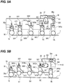
FIG. 5 is a cross-sectional view for explaining an operation in which the primary transfer roller 5 and the separatingroller 19 move to a separating position. Here,FIG. 5(a) illustrates a state of the color mode andFIG. 5(b) illustrates a state of the monochrome mode. - As illustrated in
FIG. 5 , both end portions of each primary transfer roller 5 is rotatably and axially supported by a pair of primary transfer bearings 34 (34Y, 34M, 34C, 34K). In addition, while the movement of theintermediate transfer belt 7 in the moving direction is regulated by thefront frame 23F and therear frame 23R, the primary transfer bearing 34 is fitted and held to be elevatable vertically upwardly and downwardly. The primary transfer bearing 34 is biased together with the primary transfer roller 5 downward in the vertical direction by primary transfer springs 35 (35Y, 35M, 35C, 35K) as a spring member, and as a biasing unit. That is, each of the primary transfer rollers 5 is biased against theintermediate transfer belt 7 by the biasing force of the primary transfer spring 35. - In addition, both end portions of the separating roller 19 (stretching member) disposed at a position adjacent to the upstream side of the
primary transfer roller 5Y at the most upstream position with respect to the moving direction of theintermediate transfer belt 7 and stretching theintermediate transfer belt 7 are rotatably and axially supported by the separatingroller bearing 36. In addition, while the movement of theintermediate transfer belt 7 in the moving direction is regulated by thefront frame 23F and therear frame 23R, it is fitted and held to be elevatable vertically upwardly and downwardly. In addition, it is biased together with the separatingroller 19 downwardly in the vertical direction by the separatingroller spring 39. - In addition, separating
cams 37 as cam members are provided at both end portions of the separatingshaft 28. - Next, a separating operation when a part of the primary transfer roller 5 moves from the abutting position which abuts with the
intermediate transfer belt 7 to the separating position which is separated from theintermediate transfer belt 7 will be described. - When switching from the color mode to the monochrome mode, the driving power is input to the separating
coupling 30 from a separating driving unit (not illustrated) which has received a signal from theCPU 60. Therefore, the driving power is transmitted to the separatingshaft 28, and the separatingcam 37 is rotated by 90 degrees in a direction of an arrow R2 (a state changes from a state ofFIG. 5(a) to a state ofFIG. 5(b) ). - When the separating
cam 37 rotates in the direction of the arrow R2, the separatingcam 37 biases theslide biasing surface 44 of the separatingslider 40. Therefore, the separatingslider 40 slides in a direction of an arrow K1. - When the separating
slider 40 slides in the direction of the arrow K1, protrusions 34Ya, 34Ma, and 34Ca of theprimary transfer bearings surfaces primary transfer roller 5K of black K move from the abutting position which abuts with theintermediate transfer belt 7 to the separating position which is separated from theintermediate transfer belt 7. - That is, in the present embodiment, the separating
slider 40 and the separatingcam 37 are moving mechanisms capable of moving theprimary transfer rollers cam 37. In addition, as the elevatingsurfaces slider 40 guide the protrusions 34Ya, 34Ya, and 34Ma (guided portions), theprimary transfer rollers - In addition, as the separating
slider 40 slides, theprotrusion 36a of the separatingroller bearing 36 is pushed up by the elevatingsurface 42, and the separatingroller 19 moves in a direction away from theintermediate transfer belt 7 from a position (third position) before the movement. At this time, the moving amount of the separatingroller 19 is set to be smaller than the moving amounts of theprimary transfer rollers roller 19 after the movement is a position closer than the intermediate transfer position than the positions of theprimary transfer rollers intermediate transfer belt 7 is stretched along the separating roller 19 (the state ofFIG. 5(b) ). -
FIG. 6 is a cross-sectional view of theintermediate transfer unit 10 in the monochrome mode and the color mode. Here,FIG. 6(a) illustrates the state of the color mode andFIG. 6(b) illustrates the state of the monochrome mode. - The surplus length of the
intermediate transfer belt 7, which is caused by the change in the stretching layout of theintermediate transfer belt 7 according to the mode change, is absorbed by the movement of thetension roller 17 from the position indicated by a dashed line inFIG. 6(b) to a position indicated by a solid line. At this time, since the biasing force of thetension spring 20 against theintermediate transfer belt 7 decreases, the tension of theintermediate transfer belt 7 decreases, and the tension of theintermediate transfer belt 7 at the primary transfer nip portion NK also decreases. - At this time, since the tension from the
intermediate transfer belt 7 against the biasing force of theprimary transfer spring 35K decreases, the position of theprimary transfer roller 5K changes like the position change of theprimary transfer roller 55 from the solid line to the dashed line illustrated inFIG. 7 . Therefore, the distance L3 from the contact point P4 between thephotosensitive drum 1K and theintermediate transfer belt 7 illustrated inFIG. 2 to the contact point P5 between theprimary transfer roller 5K and theintermediate transfer belt 7 is reduced, and the primary transfer current may change and image defect may occur. - In the present embodiment, the biasing force of the
primary transfer spring 35K is reduced by the following configuration to suppress the change in the position of theprimary transfer roller 5K due to the change in the stretching layout. Therefore, the change in the primary transfer current is suppressed, and the occurrence of image defect is suppressed. - That is, as illustrated in
FIG. 5 , while the movement of theintermediate transfer belt 7 in the moving direction is regulated by thefront frame 23F and therear frame 23R, a variable spring seat 38 (first support portion) on which theprimary transfer spring 35K is installed is fitted and held to be elevatable upwardly and downwardly in the vertical direction. In addition, thevariable spring seat 38 is biased in the K2 direction which is upward in the vertical direction by theprimary transfer spring 35K (elastic member). - Then, when switching from the color mode to the monochrome mode, the
protrusion 38a of thevariable spring seat 38 is pushed up by the springseat elevating surface 43 of the separatingslider 40 by the sliding of the separatingslider 40 in the direction of the arrow K1 due to the rotation of the separatingcam 37. That is, thevariable spring seat 38 moves to a position away from theintermediate transfer belt 7 by interlocking with the movement of theprimary transfer rollers intermediate transfer belt 7. In addition, the movement thereof is performed by guiding theprotrusion 38a as the guided portion to the springseat elevating surface 43 as the guide portion. That is, the separatingslider 40 and the separatingcam 37 are interlocking mechanism for moving thevariable spring seat 38 to a position away from theintermediate transfer belt 7 by interlocking with the movement of theprimary transfer rollers intermediate transfer belt 7. - Due to this, the biasing force of the
primary transfer spring 35K as the spring member when theprimary transfer rollers primary transfer rollers primary transfer roller 5K (second transfer member) against theintermediate transfer belt 7 by theprimary transfer spring 35K is reduced. At this time, the biasing force of theprimary transfer spring 35K and the movement amount of thevariable spring seat 38 are set such that the distance L3 from the contact point P4 to the contact point P5 illustrated inFIG. 2 during the image formation does not change in the monochrome mode and the color mode. At the time of the image formation, the biasing force of theprimary transfer roller 5K against theintermediate transfer belt 7 changes according to the magnitude of the primary transfer bias, in addition to the stretching layout switching of theintermediate transfer belt 7, and thus the setting is also performed in consideration of this. That is, the primary transfer bearing 34K (second support portion), theprimary transfer spring 35K, thevariable spring seat 38, the separatingslider 40, and the separatingcam 37 are a changing mechanism for changing the biasing force for biasing theprimary transfer roller 35K against theintermediate transfer belt 7. The changing mechanism also includes the interlocking mechanism. - With such a configuration, in the monochrome mode and the color mode, it is possible to suppress the change in the primary transfer current flowing from the
primary transfer roller 5K to thephotosensitive drum 1K, and it is possible to suppress the occurrence of image defect. - The switching from the monochrome mode to the color mode is performed by an operation opposite to the above separating operation when the separating
cam 37 rotates by 90 degrees in the direction opposite to the direction of the arrow R2 illustrated inFIG. 5(a) . - In this embodiment, the compression spring is used as the biasing unit for biasing the
primary transfer roller 5K, but the present invention is not limited thereto. That is, it may be configured as long as the biasing force for biasing the primary transfer roller 5 not separated against theintermediate transfer belt 7 is reduced in a state in which a part of the plurality of primary transfer rollers 5 is separated from theintermediate transfer belt 7. Further, even when the primary transfer roller 5 is pressed against theintermediate transfer belt 7 with a configuration other than biasing the primary transfer roller 5, the effect of the present invention can be obtained. - In addition, although the configuration in which the
primary transfer roller 5K of black K is not separated from theintermediate transfer belt 7 has been described in the present embodiment, the present invention is not limited thereto. That is, even when the primary transfer roller for transferring a developer of a color having a high use frequency to theintermediate transfer belt 7 is not separated, or even when the primary transfer rollers of a plurality of colors are not separated, the effect of the present invention can be obtained. - The present invention is not limited to the above embodiments, and various modifications and variations can be made without departing from the spirit and scope of the present invention. Therefore, the following claims are attached so as to make public the scope of the present invention.
- This application claims the benefit of Japanese Patent Application No.
2016-080717, filed April 14, 2016 - The present invention relates to an image forming apparatus and has industrial applicability.
-
- 1
- photosensitive drum
- 5
- primary transfer roller
- 7
- intermediate transfer belt
- 10
- intermediate transfer unit
- 19
- separating roller
- 35
- primary transfer spring
- 37
- separating cam
- 38
- variable spring seat
- 40
- separating slider
- 43
- spring seat elevating surface
- A
- image forming apparatus
Claims (9)
- An intermediate transfer unit, which is supported by an image forming apparatus, the intermediate transfer unit comprising:an endless intermediate transfer belt onto which developer images respectively formed on surfaces of first and second photosensitive members are transferred;first and second transfer members which are respectively disposed corresponding to the first and second photosensitive members and abut on an inner peripheral surface of the intermediate transfer belt to transfer the developer image onto the intermediate transfer belt, wherein a first position which is a downstream side end portion of a region in which the photosensitive member and the intermediate transfer belt abut at the time of the transfer in a moving direction of the intermediate transfer belt is disposed upstream of a second position which is an upstream side end portion of a region in which the intermediate transfer belt and the transfer member corresponding to the photosensitive member abut;a moving mechanism which is capable of moving to an abutting position at which the first transfer member abuts against the intermediate transfer belt and a separating position at which the first transfer member is separated from the intermediate transfer belt; anda changing mechanism which changes a biasing force for abutting the second transfer member against the intermediate transfer belt, wherein the biasing force is changed such that the biasing force when the first transfer member is at the separating position becomes weaker than the biasing force when the first transfer member is at the abutting position.
- The intermediate transfer unit according to claim 1, wherein the changing mechanism changes the biasing force such that a distance between the first position and the second position along the intermediate transfer belt becomes equal when the first transfer member is at the abutting position and when the first transfer member is at the separating position.
- The intermediate transfer unit according to claim 1 or 2, wherein the changing mechanism comprises:a first support portion whose position is changed;a second support portion which supports the second transfer member; andan elastic member which is disposed between the first support portion and the second support portion and generates the biasing force,wherein a position of the first support portion in the changing mechanism is moved so as be positioned farther away from the intermediate transfer belt when the first transfer member is at the separating position than when the first transfer member is at the abutting position.
- The intermediate transfer unit according to claim 3, wherein the changing mechanism has an interlocking mechanism which moves the first support portion by interlocking with the movement between the abutting position and the separating position of the first transfer member due to the moving mechanism.
- The intermediate transfer unit according to claim 4, wherein the interlocking mechanism includes a cam member, and the first support portion is moved as the cam member is moved.
- The intermediate transfer unit according to any one of claims 1 to 5, wherein the first transfer member is provided in plurality, a stretching member which stretches the intermediate transfer belt from an inner peripheral surface side at a position adjacent to the upstream side of the first transfer member positioned at a most upstream position in the moving direction of the intermediate transfer belt is provided, and the stretching member moves from a third position to a fourth position at which the tension of the intermediate transfer belt is lower than at the third position, along with the movement of the first transfer member from the abutting position to the separating position.
- The intermediate transfer unit according to any one of claims 1 to 6, further comprising:a tension roller which abuts against the inner peripheral surface of the intermediate transfer belt and applies a tension to the intermediate transfer belt;a plurality of stretching rollers which stretch the intermediate transfer belt;a frame which supports the plurality of stretching rollers;a tension bearing which is movably supported with respect to the frame and rotatably and axially supports the tension roller; anda tension spring which is disposed between the tension bearing and the frame and applies a biasing force to the tension roller.
- The intermediate transfer unit according to any one of claims 1 to 7, wherein the second transfer member is a transfer member which transfers a black developer image onto the intermediate transfer belt.
- An image forming apparatus comprising:first and second photosensitive members; andthe intermediate transfer unit according to any one of claims 1 to 8.
Applications Claiming Priority (2)
| Application Number | Priority Date | Filing Date | Title |
|---|---|---|---|
| JP2016080717A JP6708469B2 (en) | 2016-04-14 | 2016-04-14 | Intermediate transfer unit and image forming apparatus |
| PCT/JP2017/011113 WO2017179368A1 (en) | 2016-04-14 | 2017-03-21 | Intermediate transfer unit and image forming device |
Publications (1)
| Publication Number | Publication Date |
|---|---|
| EP3444679A1 true EP3444679A1 (en) | 2019-02-20 |
Family
ID=60041721
Family Applications (1)
| Application Number | Title | Priority Date | Filing Date |
|---|---|---|---|
| EP17782186.5A Withdrawn EP3444679A1 (en) | 2016-04-14 | 2017-03-21 | Intermediate transfer unit and image forming device |
Country Status (6)
| Country | Link |
|---|---|
| US (1) | US10317821B2 (en) |
| EP (1) | EP3444679A1 (en) |
| JP (1) | JP6708469B2 (en) |
| KR (1) | KR20180123094A (en) |
| CN (1) | CN109074020A (en) |
| WO (1) | WO2017179368A1 (en) |
Families Citing this family (5)
| Publication number | Priority date | Publication date | Assignee | Title |
|---|---|---|---|---|
| JP7433780B2 (en) * | 2019-05-31 | 2024-02-20 | キヤノン株式会社 | Image forming device |
| JP7388081B2 (en) * | 2019-09-20 | 2023-11-29 | 富士フイルムビジネスイノベーション株式会社 | image forming device |
| JP7494062B2 (en) * | 2020-09-09 | 2024-06-03 | キヤノン株式会社 | Image forming device |
| JP7686467B2 (en) * | 2021-06-17 | 2025-06-02 | キヤノン株式会社 | Image forming device |
| JP2025129703A (en) * | 2024-02-26 | 2025-09-05 | 京セラドキュメントソリューションズ株式会社 | Method for assembling a belt conveyor |
Family Cites Families (12)
| Publication number | Priority date | Publication date | Assignee | Title |
|---|---|---|---|---|
| JP3992704B2 (en) * | 2004-09-28 | 2007-10-17 | シャープ株式会社 | Transfer belt device and image forming apparatus |
| JP2008298835A (en) * | 2007-05-29 | 2008-12-11 | Kyocera Mita Corp | Image forming apparatus |
| JP5151929B2 (en) * | 2008-11-25 | 2013-02-27 | コニカミノルタビジネステクノロジーズ株式会社 | Image forming apparatus |
| JP4748243B2 (en) * | 2009-03-27 | 2011-08-17 | 富士ゼロックス株式会社 | Intermediate transfer device, transfer device, and image forming apparatus |
| JP4934732B2 (en) | 2010-03-08 | 2012-05-16 | シャープ株式会社 | Transfer device |
| JP5014455B2 (en) * | 2010-04-12 | 2012-08-29 | シャープ株式会社 | Transfer device and image forming apparatus |
| JP5470291B2 (en) * | 2011-01-31 | 2014-04-16 | 京セラドキュメントソリューションズ株式会社 | Intermediate transfer unit and color image forming apparatus having the same |
| JP2012247756A (en) | 2011-05-31 | 2012-12-13 | Canon Inc | Image forming device |
| KR20130059991A (en) * | 2011-11-29 | 2013-06-07 | 삼성전자주식회사 | Transfer unit and image forming apparatus having the same |
| JP2014106442A (en) * | 2012-11-29 | 2014-06-09 | Kyocera Document Solutions Inc | Intermediate transfer unit and color image forming apparatus including the same |
| JP2015087714A (en) * | 2013-11-01 | 2015-05-07 | カシオ電子工業株式会社 | Image formation device |
| JP2017015775A (en) * | 2015-06-26 | 2017-01-19 | キヤノン株式会社 | Image forming apparatus |
-
2016
- 2016-04-14 JP JP2016080717A patent/JP6708469B2/en not_active Expired - Fee Related
-
2017
- 2017-03-21 EP EP17782186.5A patent/EP3444679A1/en not_active Withdrawn
- 2017-03-21 KR KR1020187029299A patent/KR20180123094A/en not_active Abandoned
- 2017-03-21 CN CN201780023231.6A patent/CN109074020A/en active Pending
- 2017-03-21 WO PCT/JP2017/011113 patent/WO2017179368A1/en not_active Ceased
-
2018
- 2018-10-09 US US16/155,224 patent/US10317821B2/en not_active Expired - Fee Related
Also Published As
| Publication number | Publication date |
|---|---|
| US20190041774A1 (en) | 2019-02-07 |
| JP6708469B2 (en) | 2020-06-10 |
| CN109074020A (en) | 2018-12-21 |
| KR20180123094A (en) | 2018-11-14 |
| JP2017191216A (en) | 2017-10-19 |
| US10317821B2 (en) | 2019-06-11 |
| WO2017179368A1 (en) | 2017-10-19 |
Similar Documents
| Publication | Publication Date | Title |
|---|---|---|
| US10317821B2 (en) | Intermediate transfer unit and image forming apparatus | |
| US10322893B2 (en) | Image forming apparatus | |
| JP5477713B2 (en) | Image forming apparatus | |
| JP2010281943A (en) | Image forming apparatus | |
| JP2010009015A (en) | Color image forming apparatus | |
| JP6380835B2 (en) | Transfer device and image forming apparatus | |
| JP6207150B2 (en) | Image forming apparatus | |
| JP6061649B2 (en) | Belt conveying apparatus and image forming apparatus | |
| JP2011013608A (en) | Image forming apparatus | |
| EP2835695A1 (en) | Image forming device | |
| US9563170B2 (en) | Image forming apparatus configured to use a common driving source for image bearing members | |
| JP2007034085A (en) | Image forming apparatus | |
| JP2011059608A (en) | Image forming apparatus | |
| JP7229695B2 (en) | image forming device | |
| JP5627403B2 (en) | Image forming apparatus | |
| JP5472811B2 (en) | Image forming apparatus | |
| JP5169908B2 (en) | Transfer device and image forming apparatus | |
| JP2014109656A (en) | Image forming apparatus | |
| JP7433780B2 (en) | Image forming device | |
| JP2011033771A (en) | Paper conveying device and image forming apparatus | |
| JP2018092090A (en) | Image formation device | |
| JP5769540B2 (en) | Image forming apparatus | |
| JP2017026724A (en) | Image forming apparatus | |
| JP6639104B2 (en) | Belt transport device and image forming device | |
| JP6016094B2 (en) | Transfer device and image forming apparatus |
Legal Events
| Date | Code | Title | Description |
|---|---|---|---|
| STAA | Information on the status of an ep patent application or granted ep patent |
Free format text: STATUS: THE INTERNATIONAL PUBLICATION HAS BEEN MADE |
|
| PUAI | Public reference made under article 153(3) epc to a published international application that has entered the european phase |
Free format text: ORIGINAL CODE: 0009012 |
|
| STAA | Information on the status of an ep patent application or granted ep patent |
Free format text: STATUS: REQUEST FOR EXAMINATION WAS MADE |
|
| 17P | Request for examination filed |
Effective date: 20181114 |
|
| AK | Designated contracting states |
Kind code of ref document: A1 Designated state(s): AL AT BE BG CH CY CZ DE DK EE ES FI FR GB GR HR HU IE IS IT LI LT LU LV MC MK MT NL NO PL PT RO RS SE SI SK SM TR |
|
| AX | Request for extension of the european patent |
Extension state: BA ME |
|
| STAA | Information on the status of an ep patent application or granted ep patent |
Free format text: STATUS: THE APPLICATION HAS BEEN WITHDRAWN |
|
| 18W | Application withdrawn |
Effective date: 20190515 |