EP3444657A1 - Methods and apparatus for producing highly tunable squeezed light - Google Patents
Methods and apparatus for producing highly tunable squeezed light Download PDFInfo
- Publication number
- EP3444657A1 EP3444657A1 EP18189825.5A EP18189825A EP3444657A1 EP 3444657 A1 EP3444657 A1 EP 3444657A1 EP 18189825 A EP18189825 A EP 18189825A EP 3444657 A1 EP3444657 A1 EP 3444657A1
- Authority
- EP
- European Patent Office
- Prior art keywords
- beam splitter
- output
- input
- waveguide
- substrate
- Prior art date
- Legal status (The legal status is an assumption and is not a legal conclusion. Google has not performed a legal analysis and makes no representation as to the accuracy of the status listed.)
- Pending
Links
- 238000000034 method Methods 0.000 title description 16
- 239000000758 substrate Substances 0.000 claims abstract description 33
- 230000008878 coupling Effects 0.000 claims description 48
- 238000010168 coupling process Methods 0.000 claims description 48
- 238000005859 coupling reaction Methods 0.000 claims description 48
- 230000003287 optical effect Effects 0.000 claims description 39
- 238000004891 communication Methods 0.000 claims description 6
- 230000008859 change Effects 0.000 claims description 4
- 238000006073 displacement reaction Methods 0.000 description 9
- 239000000463 material Substances 0.000 description 9
- 230000005540 biological transmission Effects 0.000 description 6
- 230000001427 coherent effect Effects 0.000 description 6
- 239000006185 dispersion Substances 0.000 description 4
- 230000001902 propagating effect Effects 0.000 description 4
- 230000004044 response Effects 0.000 description 4
- 238000004519 manufacturing process Methods 0.000 description 3
- 230000008569 process Effects 0.000 description 3
- 238000004088 simulation Methods 0.000 description 3
- 238000010521 absorption reaction Methods 0.000 description 2
- 230000008901 benefit Effects 0.000 description 2
- 230000006870 function Effects 0.000 description 2
- 230000010365 information processing Effects 0.000 description 2
- 230000001404 mediated effect Effects 0.000 description 2
- 239000004065 semiconductor Substances 0.000 description 2
- HQVNEWCFYHHQES-UHFFFAOYSA-N silicon nitride Chemical compound N12[Si]34N5[Si]62N3[Si]51N64 HQVNEWCFYHHQES-UHFFFAOYSA-N 0.000 description 2
- 230000002123 temporal effect Effects 0.000 description 2
- 101100467813 Saccharomyces cerevisiae (strain ATCC 204508 / S288c) RBS1 gene Proteins 0.000 description 1
- 229910052581 Si3N4 Inorganic materials 0.000 description 1
- VYPSYNLAJGMNEJ-UHFFFAOYSA-N Silicium dioxide Chemical compound O=[Si]=O VYPSYNLAJGMNEJ-UHFFFAOYSA-N 0.000 description 1
- XUIMIQQOPSSXEZ-UHFFFAOYSA-N Silicon Chemical compound [Si] XUIMIQQOPSSXEZ-UHFFFAOYSA-N 0.000 description 1
- 238000003491 array Methods 0.000 description 1
- 230000009286 beneficial effect Effects 0.000 description 1
- 230000002457 bidirectional effect Effects 0.000 description 1
- 230000008033 biological extinction Effects 0.000 description 1
- 238000004364 calculation method Methods 0.000 description 1
- 238000012512 characterization method Methods 0.000 description 1
- 238000005253 cladding Methods 0.000 description 1
- 230000000295 complement effect Effects 0.000 description 1
- PMHQVHHXPFUNSP-UHFFFAOYSA-M copper(1+);methylsulfanylmethane;bromide Chemical compound Br[Cu].CSC PMHQVHHXPFUNSP-UHFFFAOYSA-M 0.000 description 1
- 230000001419 dependent effect Effects 0.000 description 1
- 230000001066 destructive effect Effects 0.000 description 1
- 238000010586 diagram Methods 0.000 description 1
- 238000005516 engineering process Methods 0.000 description 1
- 238000002474 experimental method Methods 0.000 description 1
- 239000000835 fiber Substances 0.000 description 1
- 230000004907 flux Effects 0.000 description 1
- 230000014509 gene expression Effects 0.000 description 1
- 230000003993 interaction Effects 0.000 description 1
- 238000005259 measurement Methods 0.000 description 1
- 230000007246 mechanism Effects 0.000 description 1
- 230000000116 mitigating effect Effects 0.000 description 1
- 238000012986 modification Methods 0.000 description 1
- 230000004048 modification Effects 0.000 description 1
- 230000009022 nonlinear effect Effects 0.000 description 1
- 230000000644 propagated effect Effects 0.000 description 1
- 230000009467 reduction Effects 0.000 description 1
- 238000005316 response function Methods 0.000 description 1
- 229910052710 silicon Inorganic materials 0.000 description 1
- 239000010703 silicon Substances 0.000 description 1
- 229910052814 silicon oxide Inorganic materials 0.000 description 1
- 230000003595 spectral effect Effects 0.000 description 1
- 238000001228 spectrum Methods 0.000 description 1
- 230000036962 time dependent Effects 0.000 description 1
- 238000012546 transfer Methods 0.000 description 1
Images


Classifications
-
- G—PHYSICS
- G02—OPTICS
- G02F—OPTICAL DEVICES OR ARRANGEMENTS FOR THE CONTROL OF LIGHT BY MODIFICATION OF THE OPTICAL PROPERTIES OF THE MEDIA OF THE ELEMENTS INVOLVED THEREIN; NON-LINEAR OPTICS; FREQUENCY-CHANGING OF LIGHT; OPTICAL LOGIC ELEMENTS; OPTICAL ANALOGUE/DIGITAL CONVERTERS
- G02F1/00—Devices or arrangements for the control of the intensity, colour, phase, polarisation or direction of light arriving from an independent light source, e.g. switching, gating or modulating; Non-linear optics
- G02F1/01—Devices or arrangements for the control of the intensity, colour, phase, polarisation or direction of light arriving from an independent light source, e.g. switching, gating or modulating; Non-linear optics for the control of the intensity, phase, polarisation or colour
- G02F1/21—Devices or arrangements for the control of the intensity, colour, phase, polarisation or direction of light arriving from an independent light source, e.g. switching, gating or modulating; Non-linear optics for the control of the intensity, phase, polarisation or colour by interference
- G02F1/225—Devices or arrangements for the control of the intensity, colour, phase, polarisation or direction of light arriving from an independent light source, e.g. switching, gating or modulating; Non-linear optics for the control of the intensity, phase, polarisation or colour by interference in an optical waveguide structure
-
- G—PHYSICS
- G02—OPTICS
- G02B—OPTICAL ELEMENTS, SYSTEMS OR APPARATUS
- G02B6/00—Light guides; Structural details of arrangements comprising light guides and other optical elements, e.g. couplings
- G02B6/10—Light guides; Structural details of arrangements comprising light guides and other optical elements, e.g. couplings of the optical waveguide type
- G02B6/12—Light guides; Structural details of arrangements comprising light guides and other optical elements, e.g. couplings of the optical waveguide type of the integrated circuit kind
- G02B6/122—Basic optical elements, e.g. light-guiding paths
- G02B6/125—Bends, branchings or intersections
-
- G—PHYSICS
- G02—OPTICS
- G02B—OPTICAL ELEMENTS, SYSTEMS OR APPARATUS
- G02B6/00—Light guides; Structural details of arrangements comprising light guides and other optical elements, e.g. couplings
- G02B6/10—Light guides; Structural details of arrangements comprising light guides and other optical elements, e.g. couplings of the optical waveguide type
- G02B6/12—Light guides; Structural details of arrangements comprising light guides and other optical elements, e.g. couplings of the optical waveguide type of the integrated circuit kind
- G02B6/12007—Light guides; Structural details of arrangements comprising light guides and other optical elements, e.g. couplings of the optical waveguide type of the integrated circuit kind forming wavelength selective elements, e.g. multiplexer, demultiplexer
-
- G—PHYSICS
- G02—OPTICS
- G02F—OPTICAL DEVICES OR ARRANGEMENTS FOR THE CONTROL OF LIGHT BY MODIFICATION OF THE OPTICAL PROPERTIES OF THE MEDIA OF THE ELEMENTS INVOLVED THEREIN; NON-LINEAR OPTICS; FREQUENCY-CHANGING OF LIGHT; OPTICAL LOGIC ELEMENTS; OPTICAL ANALOGUE/DIGITAL CONVERTERS
- G02F1/00—Devices or arrangements for the control of the intensity, colour, phase, polarisation or direction of light arriving from an independent light source, e.g. switching, gating or modulating; Non-linear optics
- G02F1/29—Devices or arrangements for the control of the intensity, colour, phase, polarisation or direction of light arriving from an independent light source, e.g. switching, gating or modulating; Non-linear optics for the control of the position or the direction of light beams, i.e. deflection
- G02F1/31—Digital deflection, i.e. optical switching
- G02F1/313—Digital deflection, i.e. optical switching in an optical waveguide structure
-
- G—PHYSICS
- G02—OPTICS
- G02F—OPTICAL DEVICES OR ARRANGEMENTS FOR THE CONTROL OF LIGHT BY MODIFICATION OF THE OPTICAL PROPERTIES OF THE MEDIA OF THE ELEMENTS INVOLVED THEREIN; NON-LINEAR OPTICS; FREQUENCY-CHANGING OF LIGHT; OPTICAL LOGIC ELEMENTS; OPTICAL ANALOGUE/DIGITAL CONVERTERS
- G02F1/00—Devices or arrangements for the control of the intensity, colour, phase, polarisation or direction of light arriving from an independent light source, e.g. switching, gating or modulating; Non-linear optics
- G02F1/35—Non-linear optics
- G02F1/365—Non-linear optics in an optical waveguide structure
-
- G—PHYSICS
- G02—OPTICS
- G02F—OPTICAL DEVICES OR ARRANGEMENTS FOR THE CONTROL OF LIGHT BY MODIFICATION OF THE OPTICAL PROPERTIES OF THE MEDIA OF THE ELEMENTS INVOLVED THEREIN; NON-LINEAR OPTICS; FREQUENCY-CHANGING OF LIGHT; OPTICAL LOGIC ELEMENTS; OPTICAL ANALOGUE/DIGITAL CONVERTERS
- G02F1/00—Devices or arrangements for the control of the intensity, colour, phase, polarisation or direction of light arriving from an independent light source, e.g. switching, gating or modulating; Non-linear optics
- G02F1/01—Devices or arrangements for the control of the intensity, colour, phase, polarisation or direction of light arriving from an independent light source, e.g. switching, gating or modulating; Non-linear optics for the control of the intensity, phase, polarisation or colour
- G02F1/21—Devices or arrangements for the control of the intensity, colour, phase, polarisation or direction of light arriving from an independent light source, e.g. switching, gating or modulating; Non-linear optics for the control of the intensity, phase, polarisation or colour by interference
- G02F1/212—Mach-Zehnder type
Definitions
- Squeezed states of light are optical beams in which the degree of quantum fluctuations present have been suppressed to a level below that of ordinary coherent light. This reduction in quantum noise usually occurs along a particular measurement quadrature and comes at the expense of increased quantum noise along the conjugate quadrature, in keeping with the Heisenberg uncertainty principle.
- Squeezed states can be used for quantum metrology, continuous-variable (CV) quantum information processing (QIP), and quantum simulation. Generating strongly squeezed light in a compact, integrated, chip-based device with high efficiency and purity can be useful in constructing scalable quantum photonic devices. For many CV QIP applications, a high degree of control over the amount of squeezing is beneficial. Furthermore, it is often desirable to displace the generated squeezed state in phase space by an amount independent of the squeezing level.
- an apparatus includes a first beam splitter (e.g., a beam splitter that is reconfigurable and/or has a 50/50 splitting ratio), a Mach-Zehnder interferometer, and a waveguide integrated onto a substrate.
- the Mach-Zehnder interferometer has a first input coupled to a first output of the first reconfigurable beam splitter and a first output coupled to a second output of the first reconfigurable beam splitter.
- the waveguide connects a second input of the Mach-Zehnder interferometer to a second output of the Mach-Zehnder interferometer. Together, the waveguide and the Mach-Zehnder interferometer forming a ring resonator.
- the apparatus may also include a phase shifter, disposed in an arm of the Mach-Zehnder interferometer, to adjust a coupling strength of the Mach-Zehnder interferometer into the ring resonator. And it can include a second beam splitter integrated onto the substrate with a first input coupled to a second input of the first beam splitter.
- the second beam splitter may have a splitting ratio of approximately 99/1.
- an apparatus for producing squeezed light includes a substrate and a first beam splitter integrated onto the substrate.
- the first beam splitter has a first output and a second output.
- the light source also includes a ring resonator in optical communication with the first beam splitter and a tuning element in optical communication with the first beam splitter and the ring resonator.
- the tuning element is configured to change a coupling strength of the ring resonator.
- the tuning element is further configured to transmit optical signals between the first beam splitter and the ring resonator.
- an apparatus for producing a squeezed state of light includes a substrate and a first beam splitter integrated onto the substrate and configured to receive an input optical signal.
- the first beam splitter is further configured to split the input optical signal into a first portion having a first intensity and a second portion having a second intensity substantially equal to the first intensity.
- the apparatus also includes a waveguide integrated onto the substrate.
- the waveguide has an input coupled to a first output of the first beam splitter to receive the first portion of the input optical signal and an output coupled to a second output of the first beam splitter to receive the second portion of the input optical signal.
- the input and output of the waveguide are further configured to deliver the first portion and the second portion of the input optical signal back to the first beam splitter.
- a photonic chip-based source of squeezed light based on a ring resonator can displace the generated squeezed state in phase space by an amount independent of the squeezing level.
- Independent control of the phase space displacement and squeezing level makes it possible to use the squeezed displaced states in Gaussian quantum information processing, since virtually all algorithms and protocols relying on squeezed displaced states involve independent tuning of the phase space displacement and squeezing level.
- Methods and apparatus described herein employ an interferometric coupling, which allows a highly over-coupled, tunable ring resonator system to replace an array of redundant resonators.
- a tunable ring resonator system can be a useful feature for high-quality resonant squeezed light sources. Rather than making many copies of one ring in the hope that a few of them have the right coupling ratio, this tunable ring resonator system uses one ring with a tunable coupling ratio.
- the tunable ring resonator system can be provided, e.g., by the Mach-Zehnder interferometric ring-channel coupler discussed below. Eliminating the redundant resonator arrays saves space on the chip and reduces fabrication costs. Moreover, the use of a single micro-ring resonance to accomplish squeezing obviates the need for sophisticated dispersion engineering of the waveguide modes.
- a chip-based squeezed light source can be used as the nonclassical light source for photonic quantum simulation, including variational quantum estimation, and simulation of molecular vibronic spectra. It can also be used as the input for CV quantum teleportation experiments, and to create CV cluster states. Indeed, almost any application of squeezed light can benefit from such a compact, efficient, versatile and tunable squeezed light source.
- An integrated squeezed light source can include a number of photonic components, each of which can be fabricated using complementary metal-oxide-semiconductor (CMOS) fabrication processes.
- CMOS complementary metal-oxide-semiconductor
- These photonic components include, but are not limited to directional couplers (DCs), reconfigurable beam splitters (RBSs), ring resonators (RRs), and Mach-Zehnder interferometric ring-channel couplers (MZIRCCs).
- a DC includes two waveguides brought into close proximity of one another over a set propagation length to enable the transfer of light intensity between them.
- An RBS includes two directional couplers, arranged sequentially to form a Mach-Zehnder interferometer, with a controllable phase delay on one intermediate arm, permitting a tunable extinction and transmission ratio through each port (see, e.g., FIG. 1 below). This component thus behaves as a beam splitter with configurable transmission and reflection ratios.
- a RR can be implemented as a waveguide wrapped around on itself, leading to resonant enhancement of nonlinear optical processes within the ring waveguide.
- an MZIRCC can be implemented as an RBS-based coupler between a waveguide and a ring resonator, permitting wavelength-dependent tunability of the coupling strength between a waveguide and ring resonator (see, e.g., FIG. 2 below).
- the coupling strength used herein refers to the fraction of light that is coupled between the subsystems (e.g., channel waveguide and ring resonator waveguide) in a single pass (i.e. before buildup in the resonator).
- FIG. 1 shows a schematic of a Reconfigurable Beam Splitter (RBS) 100 including a first directional coupler (DC1) 110 and a second direction coupler (DC2) 120 placed sequentially, with the relative optical phase ⁇ between the intervening waveguide segments controlled thermo-optically by the current through a microheater 130 (shaded overlay). Other means of controlling this phase, such as electro-optic phase shifters, can also be used.
- the RBS 100 also includes two input ports 112a and 112b, as well as two output ports 122a and 122b.
- the architecture shown in FIG. 1 can realize an effective Mach-Zehnder interferometer with tunable transmission between the input fields ( E 1 , E 2 ) and the output fields ( E 3 , E 4 ).
- FIG. 2 shows a schematic of a Mach-Zehnder interferometric ring-channel coupler (MZIRCC) 200.
- the MZIRCC includes an RBS 210 having one output waveguide 214 fed back into one input waveguide 212.
- the RBS 210 can be substantially similar to the RBS 100 shown in FIG. 1 and described above.
- the feedback is achieved by a waveguide 220 and a phase shifter 230 operably coupled to the waveguide.
- the input waveguide 212, the waveguide 220, and the output waveguide 214 therefore form a ring resonator 240 coupled to an interferometer (i.e., the RBS 210) with tunable phase difference ⁇ thermo-optically controlled by the microheater current.
- This current tunes the effective coupling strength between the input/output channels (211 and 213, respectively, in FIG. 2 ) and the ring resonator 240.
- the phase shifter 230 e.g., a microheater mounted on a segment of the ring resonator 240 can provide phase ⁇ per round trip. Adjusting the electrical current through the phase shifter 230 can therefore change the effective optical length of the ring resonator 240, allowing the resonance frequencies and free spectral range of the ring resonator 240 to be fine-tuned.
- FIG. 3A is a schematic of an integrated squeezed light source 300
- FIG. 3B shows a squeezer portion of the integrated squeezed light source 300 shown in FIG. 3A with the field operators labelled.
- the entire light source 300 can be fabricated on a common substrate (also referred to as a chip).
- at least a portion of the light source 300 is fabricated on a common substrate and the remaining portions can be fabricated one or more different substrates.
- the squeezed light source 300 includes a first RBS 310 (labelled as RBS1), with a first phase shifter 315, which controls the coupling ratio of the first RBS 310.
- the first RBS 310 also includes two inputs 312a and 312b and two outputs 314a and 314b.
- the first input 312a of the first RBS 310 is coupled to a pump light source (not shown), such as a pump laser.
- the pump laser can be integrated onto or coupled to the chip.
- the second input 312b of the first RBS 310 is coupled to one input of a second RBS 320 (labelled as RBS2).
- the second RBS 320 includes a second phase shifter 325, which controls the coupling ratio of the second RBS 320.
- the second RBS 320 also includes two inputs 322a and 322b and two outputs 324a and 324b.
- FIG. 3A illustrates that the first RBS 310 and the second RBS 320 are reconfigurable, non-reconfigurable beam splitters can also be used in place of one or both of the reconfigurable beam splitters.
- the light source 300 also includes an MZIRCC 330, which has two inputs 332a and 332b and two outputs 334a and 334b.
- the second output 314b of the first RBS 310 is coupled to the first input 332a of the MZIRCC 330, which includes a third phase shifter 335.
- the first output 314a of the first RBS 310 is coupled to the first output 334a of the MZIRCC 330.
- the second input 332b of the MZIRCC 330 and the second output 334b are coupled together by a waveguide 336 to form a RR.
- a phase shifter 337 is operably coupled to the waveguide 336. This coupling arrangement causes light to propagate bi-directionally through the RR (e.g., as in a Sagnac interferometer).
- the light source 300 further includes two output ports 340a and 340b.
- the output 324a and 324b of the second RBS 320 can be used as the ports 340a and 340b of the entire light source 300.
- the output ports 340a and 340b of the light source 300 can be separate components (but optically coupled to the outputs 324a and 324b, respectively, of the second RBS 320).
- FIGS. 3A and 3B show that the coupling strength of the RR is adjusted using a Mach-Zehnder interferometer (MZI).
- MZI Mach-Zehnder interferometer
- the coupling strength can be adjusted via thermal tuning of the coupling region.
- the coupling strength can be adjusted via coupled resonator-mediated coupling, tunable by shifting the resonance position of the mediating resonator.
- the coupling strength can be adjusted via strain tuning in the coupling region, or tuning by other mechanical means.
- Squeezing of the both clockwise- and counterclockwise-circulating modes in the RR is achieved via self-phase modulation arising from the third-order nonlinear optical response of the ring resonator medium.
- the coherent carrier pump light coupled back (e.g. via 314a and 314b) through the first RBS 310 undergoes destructive interference at channel B (i.e. the second input 312b of the first RBS 310) and is extinguished, so that only quadrature squeezed vacuum emerges from that channel B.
- the squeezed vacuum from channel B is mixed with coherent light from displacement input channel C (i.e., input 322b of the second RBS 320), resulting in displaced squeezed light at the outputs D1 and D2 (e.g., outputs 324a and 324b of the second RBS 320).
- the squeezed light source shown in FIGS. 3A and 3B can be fabricated on an integrated photonic chip, with the waveguide cores of the components constructed from a material having a suitable third-order nonlinear optical response (e.g., silicon nitride).
- the waveguide cores provide high third-order nonlinearity that is transparent up to three-photon-absorption at the operational wavelength(s).
- the waveguide material can have little to no linear or two-photon absorption at the relevant wavelengths (e.g., the waveguide material should have a bandgap greater than twice the photon energy at the operational wavelength).
- the waveguides can be designed such that optical modes propagating within the waveguides are well confined to the region of highest nonlinearity.
- the squeezed light source may be formed of single-mode waveguides with silicon nitride cores and silicon oxide claddings on a silicon chip forming the basic substrate.
- suitable materials include, for example, aluminum nitride and Hydex.
- a coherent pump injected an optical signal into the input channel A i.e. first input 312a
- first RBS 310 with phase ⁇ 1 tuned before operation.
- the optical signal is then monitored and stabilized during operation to obtain a 50% transmission ratio through each output port 314a and 314b of the first RBS 310, i.e., the two output signals at 314a and 314b have substantially the same intensity (or power).
- the optical signal thereby propagates both clockwise and counterclockwise in the MZIRCC 330 with equal intensity in either orientation.
- the MZIRCC 330 couples the optical signal to the RR in both directions, thereby exciting both the clockwise- and counterclockwise-circulating modes therein.
- the circulating intensities of the pump modes for both directions i.e. clockwise- and counterclockwise-circulating pump modes) are also substantially equal.
- the phase ⁇ c in the MZIRCC 330 controls the extrinsic quality factor of the RR mode, which can directly impact the resonance linewidth and coupling condition of both the clockwise- and counterclockwise-circulating pump modes in the RR.
- Possible coupling conditions include, for example, under coupling, over coupling, or critical coupling.
- the phase depends on the various path lengths, which may be difficult to control precisely during fabrication. It can be adjusted as desired during device characterization, then stabilized and monitored during the operation. As discussed below, the ability to tune this coupling condition has a marked impact on the quality of the squeezed light for the output of an RR-based squeezer.
- the squeezing bandwidth is also tuned by ⁇ c .
- the light emerging from the RR is incident on both output ports 314a and 314b of the first RBS 310 (i.e., from the MZIRCC 330 on the right side of FIG. 3A towards the first RBS 310 on the left side of FIG. 3A ). Since the optical paths for both directions (i.e. directions within the Sagnac loop) are automatically balanced, the coherent pump carrier portion of the optical signal is extinguished at port B (i.e. 312b).
- the squeezed vacuum from port 312b is mixed with coherent light from the input 322b of the second RBS 320.
- the phase ⁇ 2 is tuned before operation, then set and stabilized to obtain a very high transmission ratio between channels C (i.e. 322b) and channel D1 (i.e. 324a or 340a).
- the transmission ratio can be about 99% or higher, so that very little squeezed light is lost to port D2 (i.e. 324b or 340b), the output of which is discarded.
- the exact coupling ratio depends on the available power and how much power can be coupled into port C (i.e. 322b).
- the resultant light exiting output port 324b is a displaced squeezed state.
- the degree of displacement is controlled by the input to the port 322b, which is independent of the amount of squeezing, the degree of displacement and squeezing are independently tunable.
- This tunability is provided by a separate displacer stage, since the nonlinear process that generates the squeezed light in the squeezer provides a degree of squeezing that is directly related to the initial displacement of the pump light.
- a separate displacer component e.g., second RBS 320 decouples the displacement and squeezing operations.
- photon field operators ⁇ ( z ) defined such that the commutators
- the dispersion should be small enough that the group velocity is (substantially) constant over the operational bandwidth, which be made narrow enough to achieve the desired dispersion.
- the various fields propagating in the full device can be modeled by these mathematical objects (e.g., ⁇ ( z )).
- the squeezer segment of the device As illustrated FIG. 3B , at the input 312a to the first RBS 310, the field into which the pump is injected is described by field operator ⁇ P ; the other (vacuum) input 312b to the first RBS 310 is described by field operator ⁇ 0 .
- Standard cavity input-output theory can be used to calculate the intraresonator dynamics, from which squeezing occurs due to the self-phase modulation interaction arising from the third-order nonlinear optical response of the ring medium. Since the entire structure has a nonlinear-optical response, squeezing can occur in every waveguide portion. But the massive field enhancement in the RR makes it a good approximation to neglect nonlinear effects elsewhere.
- the output fields ⁇ ⁇ > can then be propagated to the first RBS 310, where they are transformed to fields ⁇ out and ⁇ X via the same relation as Equation (3).
- the statistics of the field operator ⁇ out reveal quadrature squeezing across the bandwidth of the ring resonance used; the displacement operation then produces a final device output corresponding to displaced squeezed vacuum.
- This ratio can be understood as the probability that a photon in the RR can be collected in the relevant output channel, rather than be lost to scattering.
- ⁇ is close to unity, almost all the light in the resonator is collected, directly mitigating the corruption of the squeezed light output by the contribution from the noise fields N( t ). Since Q ext is directly related to the effective coupling strength given by the MZIRCC 330, which is in turn controllable by the microheater current I c .
- FIG. 4 shows a schematic of a light source 400 including a spiral waveguide for generating squeezed state of light.
- the light source 400 includes a first RBS 410 that further includes two inputs 412a and 412b as well as two output 414a and 414b.
- a phase shifter 415 is operably coupled to one arm of the first RBS 410 to control the splitting ratio of the first RBS 410.
- Optical signals delivered by the first RBS 410 are sent to a waveguide 430 (e.g., a spiral waveguide), where the optical signals undergo nonlinear modulations (e.g., third-order nonlinear modulation).
- the waveguide 430 includes an input 432a coupled to the first output 414a of the first RBS 410 and an output 432b coupled to the second output 414b of the first RBS 410.
- the waveguide 430 can have sufficient nonlinearity and length to allow for squeezed light generation when pumped by an optical pulse train of suitable duration and peak power.
- the waveguide 430 is spiral as illustrated in FIG. 4 .
- the waveguide 430 can be straight (or linear).
- the waveguide 430 can include a bent waveguide.
- the tunability of the first RBS 410 is employed to control the magnitude and phase angle of the generated squeezed light.
- the waveguide 430 may also be engineered (or configured) to tailor the bandwidth and temporal mode structure of the generated squeezed light.
- the first RBS 410 then delivers the generated squeezed light, via the input 412b, to a second RBS 420.
- the second RBS 420 includes a first input 422a to receive the squeezed light from the input 412b of the first RBS 410.
- the second RBS 420 also includes a second input 422b to receive a displacement input so as to generate a displaced squeezed light, which is transmitted out of the second RBS 420 via one or both outputs 424a and 424b.
- a phase shifter 425 is operably coupled to one arm of the second RBS 420 to control the splitting ratio of the second RBS 420.
- the light source 400 further includes two output ports 440a and 440b.
- the output 424a and 424b of the second RBS 420 can be used as the ports 440a and 440b of the entire light source 400.
- the output ports 440a and 440b of the light source 400 can be separate components (but optically coupled to the output 424a and 424b, respectively, of the second RBS 420).
- FIG. 5 shows a schematic of an apparatus 500 for generating squeezed light.
- the apparatus 500 includes a substrate 505 and a first beam splitter 510 integrated onto the substrate 505.
- the first beam splitter has a first output 514a and a second output 514b.
- the apparatus 500 also includes a ring resonator 520, in optical communication with the first beam splitter 510, to circulate light out of the first beam splitter 510.
- the optical coupling between the first beam splitter 510 and the ring resonator 520 is achieved via a tuning element 530.
- the tuning element 530 is configured to change the coupling strength of the ring resonator 520.
- the tuning element 530 is further configured as a bidirectional link between the first beam splitter 510 and the ring resonator 520, i.e. light can propagate from the first beam splitter 510 to the ring resonator 520 as well as from the ring resonator 520 back to the first beam splitter 510. Therefore, the outputs 514a and 514b can also be used as inputs.
- the tuning element 530 is configured to adjust the coupling strength via thermal tuning of the coupling region. In some embodiments, the tuning element is configured to adjust the coupling strength via coupled resonator-mediated coupling, tunable by shifting the resonance position of the mediating resonator. In some embodiments, the tuning element is configured to adjust the coupling strength via strain tuning in the coupling region, or tuning by other mechanical means.
- the tuning element 520 is configured to deliver light into the ring resonator 520 along both clockwise and counterclockwise direction.
- light propagating along the clockwise and counterclockwise directions within the ring resonator 520 can have substantially the same intensity. The squeezing of light can be achieved via similar mechanisms described above.
- the ring resonator 520 can have any other suitable shapes, such as square, rectangular, and elliptical.
- the ring resonator 520 can be a semiconductor ring resonator fabricated on the substrate 505.
- the ring resonator 520 can include a fiber ring disposed on the substrate 505.
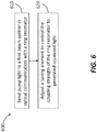
- FIG. 6 illustrates a method 600 of generating squeezed light, according to an embodiment.
- the method 600 can be implemented using any of the apparatus described herein.
- pump light is delivered to a first beam splitter in optical communication with a ring resonator, at 610.
- the coupling strength of the ring resonator is controlled by a tuning element, which is also configured to couple the pump light out of the first beam splitter into the ring resonator, at 620.
- the pump light propagates along both clockwise and counterclockwise directions within the ring resonator.
- the tuning element is further configured to couple the pump light within the ring resonator back to the first beam splitter, such that the pump light along opposite directions within the ring resonator interferes with each other. The net result is that only quadrature squeezed vacuum emerges from the first beam splitter.
- inventive embodiments are presented by way of example only and that, within the scope of the appended claims and equivalents thereto, inventive embodiments may be practiced otherwise than as specifically described and claimed.
- inventive embodiments of the present disclosure are directed to each individual feature, system, article, material, kit, and/or method described herein.
- embodiments of designing and making the technology disclosed herein may be implemented using any suitable hardware.
- inventive concepts may be embodied as one or more methods, of which an example has been provided. The acts performed as part of the method may be ordered in any suitable way. Accordingly, embodiments may be constructed in which acts are performed in an order different than illustrated, which may include performing some acts simultaneously, even though shown as sequential acts in illustrative embodiments.
- a reference to "A and/or B", when used in conjunction with open-ended language such as “comprising” can refer, in one embodiment, to A only (optionally including elements other than B); in another embodiment, to B only (optionally including elements other than A); in yet another embodiment, to both A and B (optionally including other elements); etc.
- the phrase "at least one,” in reference to a list of one or more elements, should be understood to mean at least one element selected from any one or more of the elements in the list of elements, but not necessarily including at least one of each and every element specifically listed within the list of elements and not excluding any combinations of elements in the list of elements.
- This definition also allows that elements may optionally be present other than the elements specifically identified within the list of elements to which the phrase "at least one" refers, whether related or unrelated to those elements specifically identified.
- At least one of A and B can refer, in one embodiment, to at least one, optionally including more than one, A, with no B present (and optionally including elements other than B); in another embodiment, to at least one, optionally including more than one, B, with no A present (and optionally including elements other than A); in yet another embodiment, to at least one, optionally including more than one, A, and at least one, optionally including more than one, B (and optionally including other elements); etc.
Landscapes
- Physics & Mathematics (AREA)
- Nonlinear Science (AREA)
- General Physics & Mathematics (AREA)
- Optics & Photonics (AREA)
- Engineering & Computer Science (AREA)
- Microelectronics & Electronic Packaging (AREA)
- Optical Integrated Circuits (AREA)
- Optical Modulation, Optical Deflection, Nonlinear Optics, Optical Demodulation, Optical Logic Elements (AREA)
Abstract
Description
- This application claims priority to
U.S. Application No. 62/547,324, filed August 18, 2017 - Squeezed states of light are optical beams in which the degree of quantum fluctuations present have been suppressed to a level below that of ordinary coherent light. This reduction in quantum noise usually occurs along a particular measurement quadrature and comes at the expense of increased quantum noise along the conjugate quadrature, in keeping with the Heisenberg uncertainty principle. Squeezed states can be used for quantum metrology, continuous-variable (CV) quantum information processing (QIP), and quantum simulation. Generating strongly squeezed light in a compact, integrated, chip-based device with high efficiency and purity can be useful in constructing scalable quantum photonic devices. For many CV QIP applications, a high degree of control over the amount of squeezing is beneficial. Furthermore, it is often desirable to displace the generated squeezed state in phase space by an amount independent of the squeezing level.
- Some embodiments of described herein include an apparatus for producing squeezed light. In some embodiments, an apparatus includes a first beam splitter (e.g., a beam splitter that is reconfigurable and/or has a 50/50 splitting ratio), a Mach-Zehnder interferometer, and a waveguide integrated onto a substrate. The Mach-Zehnder interferometer has a first input coupled to a first output of the first reconfigurable beam splitter and a first output coupled to a second output of the first reconfigurable beam splitter. And the waveguide connects a second input of the Mach-Zehnder interferometer to a second output of the Mach-Zehnder interferometer. Together, the waveguide and the Mach-Zehnder interferometer forming a ring resonator.
- The apparatus may also include a phase shifter, disposed in an arm of the Mach-Zehnder interferometer, to adjust a coupling strength of the Mach-Zehnder interferometer into the ring resonator. And it can include a second beam splitter integrated onto the substrate with a first input coupled to a second input of the first beam splitter. The second beam splitter may have a splitting ratio of approximately 99/1.
- In some embodiments, an apparatus for producing squeezed light includes a substrate and a first beam splitter integrated onto the substrate. The first beam splitter has a first output and a second output. The light source also includes a ring resonator in optical communication with the first beam splitter and a tuning element in optical communication with the first beam splitter and the ring resonator. The tuning element is configured to change a coupling strength of the ring resonator. The tuning element is further configured to transmit optical signals between the first beam splitter and the ring resonator.
- In some embodiments, an apparatus for producing a squeezed state of light includes a substrate and a first beam splitter integrated onto the substrate and configured to receive an input optical signal. The first beam splitter is further configured to split the input optical signal into a first portion having a first intensity and a second portion having a second intensity substantially equal to the first intensity. The apparatus also includes a waveguide integrated onto the substrate. The waveguide has an input coupled to a first output of the first beam splitter to receive the first portion of the input optical signal and an output coupled to a second output of the first beam splitter to receive the second portion of the input optical signal. The input and output of the waveguide are further configured to deliver the first portion and the second portion of the input optical signal back to the first beam splitter.
-
-
FIG. 1 shows a schematic of a Reconfigurable Beam Splitter (RBS), according to an embodiment. -
FIG. 2 shows a schematic of a Mach-Zehnder interferometric ring-channel coupler (MZIRCC) suitable for use in a squeezed light source, according to an embodiment. -
FIG. 3A shows a schematic of an integrated squeezed light source including two RBSs and an MZIRCC, according to an embodiment. -
FIG. 3B shows a schematic of a squeezer portion of the integrated squeezed light source shown inFIG. 3A with the field operators labelled, according to an embodiment. -
FIG. 4 shows a schematic of an apparatus including a spiral waveguide for generating squeezed light states, according to an embodiment. -
FIG. 5 shows a block diagram of an apparatus for generating squeezed light, according to an embodiment. -
FIG. 6 illustrates a method of generating squeezed light, according to an embodiment. - A photonic chip-based source of squeezed light based on a ring resonator can displace the generated squeezed state in phase space by an amount independent of the squeezing level. Independent control of the phase space displacement and squeezing level makes it possible to use the squeezed displaced states in Gaussian quantum information processing, since virtually all algorithms and protocols relying on squeezed displaced states involve independent tuning of the phase space displacement and squeezing level.
- Methods and apparatus described herein employ an interferometric coupling, which allows a highly over-coupled, tunable ring resonator system to replace an array of redundant resonators. Such a tunable ring resonator system can be a useful feature for high-quality resonant squeezed light sources. Rather than making many copies of one ring in the hope that a few of them have the right coupling ratio, this tunable ring resonator system uses one ring with a tunable coupling ratio. In some embodiments, the tunable ring resonator system can be provided, e.g., by the Mach-Zehnder interferometric ring-channel coupler discussed below. Eliminating the redundant resonator arrays saves space on the chip and reduces fabrication costs. Moreover, the use of a single micro-ring resonance to accomplish squeezing obviates the need for sophisticated dispersion engineering of the waveguide modes.
- A chip-based squeezed light source can be used as the nonclassical light source for photonic quantum simulation, including variational quantum estimation, and simulation of molecular vibronic spectra. It can also be used as the input for CV quantum teleportation experiments, and to create CV cluster states. Indeed, almost any application of squeezed light can benefit from such a compact, efficient, versatile and tunable squeezed light source.
- An integrated squeezed light source can include a number of photonic components, each of which can be fabricated using complementary metal-oxide-semiconductor (CMOS) fabrication processes. These photonic components include, but are not limited to directional couplers (DCs), reconfigurable beam splitters (RBSs), ring resonators (RRs), and Mach-Zehnder interferometric ring-channel couplers (MZIRCCs).
- A DC includes two waveguides brought into close proximity of one another over a set propagation length to enable the transfer of light intensity between them. An RBS includes two directional couplers, arranged sequentially to form a Mach-Zehnder interferometer, with a controllable phase delay on one intermediate arm, permitting a tunable extinction and transmission ratio through each port (see, e.g.,
FIG. 1 below). This component thus behaves as a beam splitter with configurable transmission and reflection ratios. A RR can be implemented as a waveguide wrapped around on itself, leading to resonant enhancement of nonlinear optical processes within the ring waveguide. And an MZIRCC can be implemented as an RBS-based coupler between a waveguide and a ring resonator, permitting wavelength-dependent tunability of the coupling strength between a waveguide and ring resonator (see, e.g.,FIG. 2 below). Without being bound by any particular theory or mode of operation, the coupling strength used herein refers to the fraction of light that is coupled between the subsystems (e.g., channel waveguide and ring resonator waveguide) in a single pass (i.e. before buildup in the resonator). -
FIG. 1 shows a schematic of a Reconfigurable Beam Splitter (RBS) 100 including a first directional coupler (DC1) 110 and a second direction coupler (DC2) 120 placed sequentially, with the relative optical phase φ between the intervening waveguide segments controlled thermo-optically by the current through a microheater 130 (shaded overlay). Other means of controlling this phase, such as electro-optic phase shifters, can also be used. The RBS 100 also includes twoinput ports output ports FIG. 1 can realize an effective Mach-Zehnder interferometer with tunable transmission between the input fields (E 1, E 2) and the output fields (E 3, E 4). -
FIG. 2 shows a schematic of a Mach-Zehnder interferometric ring-channel coupler (MZIRCC) 200. The MZIRCC includes an RBS 210 having oneoutput waveguide 214 fed back into oneinput waveguide 212. TheRBS 210 can be substantially similar to theRBS 100 shown inFIG. 1 and described above. The feedback is achieved by awaveguide 220 and aphase shifter 230 operably coupled to the waveguide. Theinput waveguide 212, thewaveguide 220, and theoutput waveguide 214 therefore form aring resonator 240 coupled to an interferometer (i.e., the RBS 210) with tunable phase difference φ thermo-optically controlled by the microheater current. This current tunes the effective coupling strength between the input/output channels (211 and 213, respectively, inFIG. 2 ) and thering resonator 240. The phase shifter 230 (e.g., a microheater) mounted on a segment of thering resonator 240 can provide phase φ per round trip. Adjusting the electrical current through thephase shifter 230 can therefore change the effective optical length of thering resonator 240, allowing the resonance frequencies and free spectral range of thering resonator 240 to be fine-tuned. -
FIG. 3A is a schematic of an integrated squeezedlight source 300, andFIG. 3B shows a squeezer portion of the integrated squeezedlight source 300 shown inFIG. 3A with the field operators labelled. In some embodiments, the entirelight source 300 can be fabricated on a common substrate (also referred to as a chip). In some embodiments, at least a portion of thelight source 300 is fabricated on a common substrate and the remaining portions can be fabricated one or more different substrates. - As shown in
FIG. 3A , the squeezedlight source 300 includes a first RBS 310 (labelled as RBS1), with afirst phase shifter 315, which controls the coupling ratio of thefirst RBS 310. Thefirst RBS 310 also includes twoinputs outputs first input 312a of thefirst RBS 310 is coupled to a pump light source (not shown), such as a pump laser. In some embodiments, the pump laser can be integrated onto or coupled to the chip. Thesecond input 312b of thefirst RBS 310 is coupled to one input of a second RBS 320 (labelled as RBS2). Thesecond RBS 320 includes asecond phase shifter 325, which controls the coupling ratio of thesecond RBS 320. Thesecond RBS 320 also includes twoinputs 322a and 322b and twooutputs 324a and 324b. AlthoughFIG. 3A illustrates that thefirst RBS 310 and thesecond RBS 320 are reconfigurable, non-reconfigurable beam splitters can also be used in place of one or both of the reconfigurable beam splitters. - The
light source 300 also includes anMZIRCC 330, which has twoinputs outputs second output 314b of thefirst RBS 310 is coupled to thefirst input 332a of theMZIRCC 330, which includes athird phase shifter 335. Thefirst output 314a of thefirst RBS 310 is coupled to thefirst output 334a of theMZIRCC 330. In addition, thesecond input 332b of theMZIRCC 330 and thesecond output 334b are coupled together by awaveguide 336 to form a RR. Aphase shifter 337 is operably coupled to thewaveguide 336. This coupling arrangement causes light to propagate bi-directionally through the RR (e.g., as in a Sagnac interferometer). - The
light source 300 further includes twooutput ports 340a and 340b. In some embodiments, theoutput 324a and 324b of thesecond RBS 320 can be used as theports 340a and 340b of the entirelight source 300. In some embodiments, theoutput ports 340a and 340b of thelight source 300 can be separate components (but optically coupled to theoutputs 324a and 324b, respectively, of the second RBS 320). -
FIGS. 3A and3B show that the coupling strength of the RR is adjusted using a Mach-Zehnder interferometer (MZI). In practice, any other suitable means to adjust the coupling strength of the RR can also be used. In some embodiments, the coupling strength can be adjusted via thermal tuning of the coupling region. In some embodiments, the coupling strength can be adjusted via coupled resonator-mediated coupling, tunable by shifting the resonance position of the mediating resonator. In some embodiments, the coupling strength can be adjusted via strain tuning in the coupling region, or tuning by other mechanical means. - Squeezing of the both clockwise- and counterclockwise-circulating modes in the RR is achieved via self-phase modulation arising from the third-order nonlinear optical response of the ring resonator medium. The coherent carrier pump light coupled back (e.g. via 314a and 314b) through the
first RBS 310 undergoes destructive interference at channel B (i.e. thesecond input 312b of the first RBS 310) and is extinguished, so that only quadrature squeezed vacuum emerges from that channel B. The squeezed vacuum from channel B is mixed with coherent light from displacement input channel C (i.e., input 322b of the second RBS 320), resulting in displaced squeezed light at the outputs D1 and D2 (e.g.,outputs 324a and 324b of the second RBS 320). - The squeezed light source shown in
FIGS. 3A and3B can be fabricated on an integrated photonic chip, with the waveguide cores of the components constructed from a material having a suitable third-order nonlinear optical response (e.g., silicon nitride). Put differently, the waveguide cores provide high third-order nonlinearity that is transparent up to three-photon-absorption at the operational wavelength(s). The waveguide material can have little to no linear or two-photon absorption at the relevant wavelengths (e.g., the waveguide material should have a bandgap greater than twice the photon energy at the operational wavelength). The waveguides can be designed such that optical modes propagating within the waveguides are well confined to the region of highest nonlinearity. For operation at 1550 nm, for example, the squeezed light source may be formed of single-mode waveguides with silicon nitride cores and silicon oxide claddings on a silicon chip forming the basic substrate. Other suitable materials include, for example, aluminum nitride and Hydex. - The operation of the squeezed light source shown in
FIGS. 3A and3B can be summarized as follows. A coherent pump injected an optical signal into the input channel A (i.e.first input 312a) is incident on thefirst RBS 310, with phase φ 1 tuned before operation. The optical signal is then monitored and stabilized during operation to obtain a 50% transmission ratio through eachoutput port first RBS 310, i.e., the two output signals at 314a and 314b have substantially the same intensity (or power). The optical signal thereby propagates both clockwise and counterclockwise in theMZIRCC 330 with equal intensity in either orientation. - The
MZIRCC 330 couples the optical signal to the RR in both directions, thereby exciting both the clockwise- and counterclockwise-circulating modes therein. The circulating intensities of the pump modes for both directions (i.e. clockwise- and counterclockwise-circulating pump modes) are also substantially equal. - The phase φc in the
MZIRCC 330 controls the extrinsic quality factor of the RR mode, which can directly impact the resonance linewidth and coupling condition of both the clockwise- and counterclockwise-circulating pump modes in the RR. Possible coupling conditions include, for example, under coupling, over coupling, or critical coupling. The phase depends on the various path lengths, which may be difficult to control precisely during fabrication. It can be adjusted as desired during device characterization, then stabilized and monitored during the operation. As discussed below, the ability to tune this coupling condition has a marked impact on the quality of the squeezed light for the output of an RR-based squeezer. The squeezing bandwidth is also tuned by φc . - The light emerging from the RR is incident on both
output ports MZIRCC 330 on the right side ofFIG. 3A towards thefirst RBS 310 on the left side ofFIG. 3A ). Since the optical paths for both directions (i.e. directions within the Sagnac loop) are automatically balanced, the coherent pump carrier portion of the optical signal is extinguished at port B (i.e. 312b). Furthermore, since the squeezing angle of the generated squeezed light from each direction is balanced, no entanglement is present between the outgoing light in port B (i.e., 312b) and the outgoing light to port A (i.e., 312a), i.e., the output of B (i.e. 312b) is a pure squeezed vacuum state. - The squeezed vacuum from
port 312b is mixed with coherent light from the input 322b of thesecond RBS 320. The phase φ 2 is tuned before operation, then set and stabilized to obtain a very high transmission ratio between channels C (i.e. 322b) and channel D1 (i.e. 324a or 340a). In some embodiments, the transmission ratio can be about 99% or higher, so that very little squeezed light is lost to port D2 (i.e. 324b or 340b), the output of which is discarded. The exact coupling ratio depends on the available power and how much power can be coupled into port C (i.e. 322b). The resultant light exitingoutput port 324b is a displaced squeezed state. Since the degree of displacement is controlled by the input to the port 322b, which is independent of the amount of squeezing, the degree of displacement and squeezing are independently tunable. This tunability is provided by a separate displacer stage, since the nonlinear process that generates the squeezed light in the squeezer provides a degree of squeezing that is directly related to the initial displacement of the pump light. The addition of a separate displacer component (e.g., second RBS 320) decouples the displacement and squeezing operations. - Without being bound by any particular theory, the operation of the squeezing device shown in
FIG. 3B can be understood by analyzing the relevant optical field operators within the system. Since the squeezing device usually operates on very narrowband light (e.g., 10 MHz to 10 GHz), in the channel segments (i.e., everywhere in the squeezing device except within the RR) it is sufficient to consider photon field operators ψ(z), defined such that the commutators

- It is instructive to begin with the squeezer segment of the device. As illustrated
FIG. 3B , at theinput 312a to thefirst RBS 310, the field into which the pump is injected is described by field operator ψP ; the other (vacuum)input 312b to thefirst RBS 310 is described by field operator ψ 0. The fields immediately to the right of thefirst RBS 310 are then given by
- These fields propagate through the
MZIRCC 330 to the coupling points at the RR. Though two coupling points exist, the coupling to the RR provided by theMZIRCC 330 can be modeled as an effective coupling at a single point with tunable coupling strength determined by phase φc controlled by the microheater current Ic . The input fields ψ +< (ψ -<) and output fields ψ +> (ψ ->) couple to the counterlockwise (clockwise)-circulating RR mode b +(b -). These ring modes satisfy
- Standard cavity input-output theory can be used to calculate the intraresonator dynamics, from which squeezing occurs due to the self-phase modulation interaction arising from the third-order nonlinear optical response of the ring medium. Since the entire structure has a nonlinear-optical response, squeezing can occur in every waveguide portion. But the massive field enhancement in the RR makes it a good approximation to neglect nonlinear effects elsewhere. Ultimately the result of such a calculation yields expressions for the time-dependent Heisenberg-picture output fields in terms of the input fields:

first RBS 310, where they are transformed to fields ψ out and ψX via the same relation as Equation (3). The statistics of the field operator ψ out reveal quadrature squeezing across the bandwidth of the ring resonance used; the displacement operation then produces a final device output corresponding to displaced squeezed vacuum. - The degree and quality of the squeezed output depends on the coupling ratio α,

MZIRCC 330, which is in turn controllable by the microheater current Ic . The coupling ratio α is thus a function of this current, α = α(Ic ). This obviates the need for fabricating large sequences of ring resonators with varying coupling gaps in order to identify those with the desired highly over-coupled condition (α → 1); instead, with theMZIRCC 330, a single resonator with tunable coupling can be used. -
FIG. 4 shows a schematic of alight source 400 including a spiral waveguide for generating squeezed state of light. Thelight source 400 includes afirst RBS 410 that further includes twoinputs output phase shifter 415 is operably coupled to one arm of thefirst RBS 410 to control the splitting ratio of thefirst RBS 410. Optical signals delivered by thefirst RBS 410 are sent to a waveguide 430 (e.g., a spiral waveguide), where the optical signals undergo nonlinear modulations (e.g., third-order nonlinear modulation). Thewaveguide 430 includes aninput 432a coupled to thefirst output 414a of thefirst RBS 410 and anoutput 432b coupled to thesecond output 414b of thefirst RBS 410. - The
waveguide 430 can have sufficient nonlinearity and length to allow for squeezed light generation when pumped by an optical pulse train of suitable duration and peak power. In some embodiments, thewaveguide 430 is spiral as illustrated inFIG. 4 . In some embodiments, thewaveguide 430 can be straight (or linear). In some embodiments, thewaveguide 430 can include a bent waveguide. The tunability of thefirst RBS 410 is employed to control the magnitude and phase angle of the generated squeezed light. Thewaveguide 430 may also be engineered (or configured) to tailor the bandwidth and temporal mode structure of the generated squeezed light. - Optical signals propagating in the
waveguide 430 in both directions, i.e. clockwise and counterclockwise, and travel back to thefirst RBS 410 via the twooutputs first RBS 410 then delivers the generated squeezed light, via theinput 412b, to asecond RBS 420. Thesecond RBS 420 includes afirst input 422a to receive the squeezed light from theinput 412b of thefirst RBS 410. Thesecond RBS 420 also includes asecond input 422b to receive a displacement input so as to generate a displaced squeezed light, which is transmitted out of thesecond RBS 420 via one or bothoutputs phase shifter 425 is operably coupled to one arm of thesecond RBS 420 to control the splitting ratio of thesecond RBS 420. - The
light source 400 further includes twooutput ports output second RBS 420 can be used as theports light source 400. In some embodiments, theoutput ports light source 400 can be separate components (but optically coupled to theoutput -
FIG. 5 shows a schematic of anapparatus 500 for generating squeezed light. Theapparatus 500 includes asubstrate 505 and afirst beam splitter 510 integrated onto thesubstrate 505. The first beam splitter has afirst output 514a and asecond output 514b. Theapparatus 500 also includes aring resonator 520, in optical communication with thefirst beam splitter 510, to circulate light out of thefirst beam splitter 510. The optical coupling between thefirst beam splitter 510 and thering resonator 520 is achieved via atuning element 530. Thetuning element 530 is configured to change the coupling strength of thering resonator 520. In addition, thetuning element 530 is further configured as a bidirectional link between thefirst beam splitter 510 and thering resonator 520, i.e. light can propagate from thefirst beam splitter 510 to thering resonator 520 as well as from thering resonator 520 back to thefirst beam splitter 510. Therefore, theoutputs - In some embodiments, the
tuning element 530 is configured to adjust the coupling strength via thermal tuning of the coupling region. In some embodiments, the tuning element is configured to adjust the coupling strength via coupled resonator-mediated coupling, tunable by shifting the resonance position of the mediating resonator. In some embodiments, the tuning element is configured to adjust the coupling strength via strain tuning in the coupling region, or tuning by other mechanical means. - In some embodiments, the
tuning element 520 is configured to deliver light into thering resonator 520 along both clockwise and counterclockwise direction. In some embodiments, light propagating along the clockwise and counterclockwise directions within thering resonator 520 can have substantially the same intensity. The squeezing of light can be achieved via similar mechanisms described above. - Although a circular shape is illustrated in
FIG. 5 , thering resonator 520 can have any other suitable shapes, such as square, rectangular, and elliptical. In some embodiments, thering resonator 520 can be a semiconductor ring resonator fabricated on thesubstrate 505. In some other embodiments, thering resonator 520 can include a fiber ring disposed on thesubstrate 505. -
FIG. 6 illustrates amethod 600 of generating squeezed light, according to an embodiment. Themethod 600 can be implemented using any of the apparatus described herein. In themethod 600, pump light is delivered to a first beam splitter in optical communication with a ring resonator, at 610. The coupling strength of the ring resonator is controlled by a tuning element, which is also configured to couple the pump light out of the first beam splitter into the ring resonator, at 620. The pump light propagates along both clockwise and counterclockwise directions within the ring resonator. The tuning element is further configured to couple the pump light within the ring resonator back to the first beam splitter, such that the pump light along opposite directions within the ring resonator interferes with each other. The net result is that only quadrature squeezed vacuum emerges from the first beam splitter. - While various inventive embodiments have been described and illustrated herein, those of ordinary skill in the art will readily envision a variety of other means and/or structures for performing the function and/or obtaining the results and/or one or more of the advantages described herein, and each of such variations and/or modifications is deemed to be within the scope of the inventive embodiments described herein. More generally, those skilled in the art will readily appreciate that all parameters, dimensions, materials, and configurations described herein are meant to be exemplary and that the actual parameters, dimensions, materials, and/or configurations will depend upon the specific application or applications for which the inventive teachings is/are used. Those skilled in the art will recognize, or be able to ascertain using no more than routine experimentation, many equivalents to the specific inventive embodiments described herein. It is, therefore, to be understood that the foregoing embodiments are presented by way of example only and that, within the scope of the appended claims and equivalents thereto, inventive embodiments may be practiced otherwise than as specifically described and claimed. Inventive embodiments of the present disclosure are directed to each individual feature, system, article, material, kit, and/or method described herein. In addition, any combination of two or more such features, systems, articles, materials, kits, and/or methods, if such features, systems, articles, materials, kits, and/or methods are not mutually inconsistent, is included within the inventive scope of the present disclosure.
- The above-described embodiments can be implemented in any of numerous ways. For example, embodiments of designing and making the technology disclosed herein may be implemented using any suitable hardware. Also, various inventive concepts may be embodied as one or more methods, of which an example has been provided. The acts performed as part of the method may be ordered in any suitable way. Accordingly, embodiments may be constructed in which acts are performed in an order different than illustrated, which may include performing some acts simultaneously, even though shown as sequential acts in illustrative embodiments.
- All definitions, as defined and used herein, should be understood to control over dictionary definitions, definitions in documents incorporated by reference, and/or ordinary meanings of the defined terms.
- The indefinite articles "a" and "an," as used herein in the specification and in the claims, unless clearly indicated to the contrary, should be understood to mean "at least one."
- The phrase "and/or," as used herein in the specification and in the claims, should be understood to mean "either or both" of the elements so conjoined, i.e., elements that are conjunctively present in some cases and disjunctively present in other cases. Multiple elements listed with "and/or" should be construed in the same fashion, i.e., "one or more" of the elements so conjoined. Other elements may optionally be present other than the elements specifically identified by the "and/or" clause, whether related or unrelated to those elements specifically identified. Thus, as a non-limiting example, a reference to "A and/or B", when used in conjunction with open-ended language such as "comprising" can refer, in one embodiment, to A only (optionally including elements other than B); in another embodiment, to B only (optionally including elements other than A); in yet another embodiment, to both A and B (optionally including other elements); etc.
- As used herein in the specification and in the claims, "or" should be understood to have the same meaning as "and/or" as defined above. For example, when separating items in a list, "or" or "and/or" shall be interpreted as being inclusive, i.e., the inclusion of at least one, but also including more than one, of a number or list of elements, and, optionally, additional unlisted items. Only terms clearly indicated to the contrary, such as "only one of' or "exactly one of," or, when used in the claims, "consisting of," will refer to the inclusion of exactly one element of a number or list of elements. In general, the term "or" as used herein shall only be interpreted as indicating exclusive alternatives (i.e., "one or the other but not both") when preceded by terms of exclusivity, such as "either," "one of," "only one of," or "exactly one of." "Consisting essentially of," when used in the claims, shall have its ordinary meaning as used in the field of patent law.
- As used herein in the specification and in the claims, the phrase "at least one," in reference to a list of one or more elements, should be understood to mean at least one element selected from any one or more of the elements in the list of elements, but not necessarily including at least one of each and every element specifically listed within the list of elements and not excluding any combinations of elements in the list of elements. This definition also allows that elements may optionally be present other than the elements specifically identified within the list of elements to which the phrase "at least one" refers, whether related or unrelated to those elements specifically identified. Thus, as a non-limiting example, "at least one of A and B" (or, equivalently, "at least one of A or B," or, equivalently "at least one of A and/or B") can refer, in one embodiment, to at least one, optionally including more than one, A, with no B present (and optionally including elements other than B); in another embodiment, to at least one, optionally including more than one, B, with no A present (and optionally including elements other than A); in yet another embodiment, to at least one, optionally including more than one, A, and at least one, optionally including more than one, B (and optionally including other elements); etc.
- In the claims, as well as in the specification above, all transitional phrases such as "comprising," "including," "carrying," "having," "containing," "involving," "holding," "composed of," and the like are to be understood to be open-ended, i.e., to mean including but not limited to. Only the transitional phrases "consisting of' and "consisting essentially of' shall be closed or semi-closed transitional phrases, respectively, as set forth in the United States Patent Office Manual of Patent Examining Procedures, Section 2111.03.
Claims (21)
- An apparatus for producing squeezed light, the apparatus comprising:a substrate;a first beam splitter integrated onto the substrate;a Mach-Zehnder interferometer integrated onto the substrate, the Mach-Zehnder interferometer having a first input coupled to a first output of the first beam splitter and a first output coupled to a second output of the first beam splitter; anda waveguide integrated onto the substrate and connecting a second input of the Mach-Zehnder interferometer to a second output of the Mach-Zehnder interferometer, the waveguide and the Mach-Zehnder interferometer forming a ring resonator.
- The apparatus of claim 1, wherein the first beam splitter has a splitting ratio of approximately 50/50.
- The apparatus of claim 1 or claim 2, wherein the first beam splitter is a first reconfigurable beam splitter.
- The apparatus of any of the preceding claims, further comprising:a phase shifter, disposed in an arm of the Mach-Zehnder interferometer, to adjust a coupling strength of the Mach-Zehnder interferometer into the ring resonator.
- The apparatus of any of the preceding claims, further comprising:a second beam splitter integrated onto the substrate, the second beam splitter having a first input coupled to a second input of the first beam splitter.
- The apparatus of claim 5, the second beam splitter having a splitting ratio of approximately 99/1.
- The apparatus of any of the preceding claims, wherein the waveguide is characterized by a bandgap greater than twice a photon energy at an operational wavelength of the apparatus.
- An apparatus, comprising:a substrate;a first beam splitter integrated onto the substrate, the first beam splitter having a first output and a second output;a ring resonator, in optical communication with the first beam splitter; anda tuning element in optical communication with the first beam splitter and the ring resonator, the tuning element configured to change a coupling strength of the ring resonator, the tuning element further configured to transmit optical signals between the first beam splitter and the ring resonator for generating squeezed light.
- The apparatus of claim 8, wherein the tuning element includes a Mach-Zehnder interferometer integrated onto the substrate, the Mach-Zehnder interferometer having a first input coupled to a first output of the first beam splitter and a first output coupled to a second output of the first beam splitter.
- The apparatus of claim 9, wherein the ring resonator includes:a waveguide integrated onto the substrate and connecting a second input of the Mach-Zehnder interferometer to a second output of the Mach-Zehnder interferometer.
- The apparatus of any of claims 8 to 10, wherein the first beam splitter has a splitting ratio of approximately 50/50.
- The apparatus of any of claims 8 to 11, wherein the first beam splitter is a first reconfigurable beam splitter.
- The apparatus of any of claims 8 to 12, further comprising:a second beam splitter integrated onto the substrate, the second beam splitter having a first input coupled to a second input of the first beam splitter.
- The apparatus of claim 13, the second beam splitter having a splitting ratio of approximately 99/1.
- The apparatus of any of claims 8 to 14, wherein the ring resonator is characterized by a bandgap greater than twice a photon energy at an operational wavelength of the apparatus.
- An apparatus , comprising:a substrate;a first beam splitter integrated onto the substrate and configured to receive an optical input, the first beam splitter further configured to split the optical input into a first portion having a first intensity and a second portion having a second intensity substantially equal to the first intensity; anda waveguide integrated onto the substrate, the waveguide having an input coupled to a first output of the first beam splitter to receive the first portion of the input optical signal and an output coupled to a second output of the first beam splitter to receive the second portion of the input optical signal, the input and output of the waveguide further configured to deliver the first portion and the second portion of the input optical signal back to the first beam splitter for producing a squeezed state of light.
- The apparatus of claim 16, wherein the first beam splitter is a first reconfigurable beam splitter.
- The apparatus of claim 16 or claim 17, wherein the waveguide includes a spiral waveguide.
- The apparatus of any of claims 16 to 18, further comprising:a second beam splitter integrated onto the substrate, the second beam splitter having a first input coupled to a second input of the first beam splitter.
- The apparatus of claim 19, the second beam splitter having a splitting ratio of approximately 99/1.
- The apparatus of any of claims 16 to 20, wherein the waveguide is characterized by a bandgap greater than twice a photon energy at a wavelength of the input optical signal.
Applications Claiming Priority (1)
| Application Number | Priority Date | Filing Date | Title |
|---|---|---|---|
| US201762547324P | 2017-08-18 | 2017-08-18 |
Publications (1)
| Publication Number | Publication Date |
|---|---|
| EP3444657A1 true EP3444657A1 (en) | 2019-02-20 |
Family
ID=63452391
Family Applications (1)
| Application Number | Title | Priority Date | Filing Date |
|---|---|---|---|
| EP18189825.5A Pending EP3444657A1 (en) | 2017-08-18 | 2018-08-20 | Methods and apparatus for producing highly tunable squeezed light |
Country Status (3)
| Country | Link |
|---|---|
| US (1) | US10809592B2 (en) |
| EP (1) | EP3444657A1 (en) |
| CN (1) | CN110837147B (en) |
Cited By (5)
| Publication number | Priority date | Publication date | Assignee | Title |
|---|---|---|---|---|
| WO2020232546A1 (en) * | 2019-05-22 | 2020-11-26 | Xanadu Quantum Technologies Inc. | Apparatus and methods for gaussian boson sampling |
| EP3955035A1 (en) | 2020-08-10 | 2022-02-16 | Österreichische Akademie der Wissenschaften | Photonic integrated circuit |
| CN114755870A (en) * | 2022-03-30 | 2022-07-15 | 电子科技大学 | Frequency chip entangled double photon source |
| CN116885557A (en) * | 2023-09-05 | 2023-10-13 | 武汉中科锐择光电科技有限公司 | Vacuum compression photon generation system based on waveguide structure |
| US11815696B1 (en) | 2019-09-12 | 2023-11-14 | Xanadu Quantum Technologies Inc. | Apparatus and methods for generating non-gaussian states from gaussian states |
Families Citing this family (4)
| Publication number | Priority date | Publication date | Assignee | Title |
|---|---|---|---|---|
| EP3788441A4 (en) * | 2018-05-01 | 2022-01-26 | Xanadu Quantum Technologies Inc. | Integrated devices for squeezed light generation |
| GB2575653A (en) * | 2018-07-17 | 2020-01-22 | Univ College Cork National Univ Of Ireland | Phase modulator for optical signal using multimode interference couplers |
| US20220075114A1 (en) * | 2020-09-04 | 2022-03-10 | Ciena Corporation | Resonant device improvement in PICs using spare devices to reduce power requirements |
| US11809839B2 (en) | 2022-01-18 | 2023-11-07 | Robert Lyden | Computer language and code for application development and electronic and optical communication |
Citations (4)
| Publication number | Priority date | Publication date | Assignee | Title |
|---|---|---|---|---|
| US20110032532A1 (en) * | 2007-08-18 | 2011-02-10 | Takuya Hirano | Quantum entanglement generating system and method, and quantum entanglement generating and detecting system and method |
| US20130243363A1 (en) | 2012-03-19 | 2013-09-19 | Fujitsu Optical Components Limited | Optical modulator |
| US8655114B2 (en) * | 2007-03-26 | 2014-02-18 | Massachusetts Institute Of Technology | Hitless tuning and switching of optical resonator amplitude and phase responses |
| US9235101B2 (en) * | 2013-02-19 | 2016-01-12 | The University Of Bristol | Optical source |
Family Cites Families (1)
| Publication number | Priority date | Publication date | Assignee | Title |
|---|---|---|---|---|
| US20180335570A1 (en) * | 2016-11-21 | 2018-11-22 | Government Of The United States, As Represented By The Secretary Of The Air Force | Photon generator |
-
2018
- 2018-08-17 US US16/104,424 patent/US10809592B2/en active Active
- 2018-08-20 EP EP18189825.5A patent/EP3444657A1/en active Pending
-
2019
- 2019-08-16 CN CN201910756341.4A patent/CN110837147B/en active Active
Patent Citations (4)
| Publication number | Priority date | Publication date | Assignee | Title |
|---|---|---|---|---|
| US8655114B2 (en) * | 2007-03-26 | 2014-02-18 | Massachusetts Institute Of Technology | Hitless tuning and switching of optical resonator amplitude and phase responses |
| US20110032532A1 (en) * | 2007-08-18 | 2011-02-10 | Takuya Hirano | Quantum entanglement generating system and method, and quantum entanglement generating and detecting system and method |
| US20130243363A1 (en) | 2012-03-19 | 2013-09-19 | Fujitsu Optical Components Limited | Optical modulator |
| US9235101B2 (en) * | 2013-02-19 | 2016-01-12 | The University Of Bristol | Optical source |
Non-Patent Citations (4)
| Title |
|---|
| DUTT AVIK, MILLER STEVEN, LUKE KEVIN, CARDENAS JAIME, GAETA ALEXANDER L., NUSSENZVEIG PAULO, LIPSON MICHAL: "Tunable squeezing using coupled ring resonators on a silicon nitride chip", OPTICS LETTERS, vol. 41, no. 2, 15 January 2016 (2016-01-15), US , pages 223, XP093134419, ISSN: 0146-9592, DOI: 10.1364/OL.41.000223 |
| FANG LIU ET AL: "Squeezing-enhanced fiber Mach-Zehnder interferometer for low-frequency phase measurement", APPLIED PHYSICS LETTERS, vol. 110, no. 2, 9 January 2017 (2017-01-09), US, pages 021106, XP055538585, ISSN: 0003-6951, DOI: 10.1063/1.4973895 * |
| GIOVANNI BARBAROSSA ET AL: "Theoretical Analysis of Triple-Coupler Ring-B ased Optical Guided-Wave Resonator", JOURNAL OF LIGHTWAVE TECHNOLOGY, 1 January 1995 (1995-01-01), XP055538555, Retrieved from the Internet <URL:https://ieeexplore.ieee.org/iel1/50/8367/00365200.pdf> * |
| MATTHEW TERREL ET AL: "Ring-coupled Mach-Zehnder interferometer optimized for sensing", APPLIED OPTICS, vol. 48, no. 26, 10 September 2009 (2009-09-10), WASHINGTON, DC; US, pages 4874, XP055538584, ISSN: 0003-6935, DOI: 10.1364/AO.48.004874 * |
Cited By (10)
| Publication number | Priority date | Publication date | Assignee | Title |
|---|---|---|---|---|
| WO2020232546A1 (en) * | 2019-05-22 | 2020-11-26 | Xanadu Quantum Technologies Inc. | Apparatus and methods for gaussian boson sampling |
| US11593699B2 (en) | 2019-05-22 | 2023-02-28 | Xanadu Quantum Technologies Inc. | Apparatus and methods for gaussian boson sampling |
| US11972323B2 (en) | 2019-05-22 | 2024-04-30 | Xanadu Quantum Technologies Inc. | Apparatus and methods for gaussian boson sampling |
| US11815696B1 (en) | 2019-09-12 | 2023-11-14 | Xanadu Quantum Technologies Inc. | Apparatus and methods for generating non-gaussian states from gaussian states |
| EP3955035A1 (en) | 2020-08-10 | 2022-02-16 | Österreichische Akademie der Wissenschaften | Photonic integrated circuit |
| WO2022034038A1 (en) | 2020-08-10 | 2022-02-17 | Österreichische Akademie der Wissenschaften | Photonic integrated circuit |
| CN114755870A (en) * | 2022-03-30 | 2022-07-15 | 电子科技大学 | Frequency chip entangled double photon source |
| CN114755870B (en) * | 2022-03-30 | 2023-04-07 | 电子科技大学 | Frequency chip entangled double photon source |
| CN116885557A (en) * | 2023-09-05 | 2023-10-13 | 武汉中科锐择光电科技有限公司 | Vacuum compression photon generation system based on waveguide structure |
| CN116885557B (en) * | 2023-09-05 | 2023-11-28 | 武汉中科锐择光电科技有限公司 | Vacuum compression photon generation system based on waveguide structure |
Also Published As
| Publication number | Publication date |
|---|---|
| CN110837147A (en) | 2020-02-25 |
| US20190056632A1 (en) | 2019-02-21 |
| US10809592B2 (en) | 2020-10-20 |
| CN110837147B (en) | 2021-04-23 |
Similar Documents
| Publication | Publication Date | Title |
|---|---|---|
| EP3444657A1 (en) | Methods and apparatus for producing highly tunable squeezed light | |
| Tan et al. | Ultra-high bandwidth radio frequency and microwave photonic signal processing based on kerr micro-combs | |
| Tan et al. | Photonic RF and microwave filters based on 49 GHz and 200 GHz Kerr microcombs | |
| Tan et al. | Photonic radio frequency channelizers based on Kerr optical micro-combs | |
| Tan et al. | Photonic Radio Frequency Channelizers based on Kerr Micro-combs and Integrated Micro-ring Resonators | |
| Yata et al. | Photonic-crystal diplexers for terahertz-wave applications | |
| Tan et al. | RF and microwave photonic, fractional differentiation, integration, and Hilbert transforms based on Kerr micro-combs | |
| Moss | RF and microwave photonic high bandwidth signal processing based on Kerr micro-comb sources | |
| Tan et al. | High bandwidth temporal RF photonic signal processing with Kerr micro-combs: integration, fractional differentiation and Hilbert transforms | |
| EP3788441A1 (en) | Integrated devices for squeezed light generation | |
| Tan et al. | RF photonic signal processing with Kerr micro-combs: integration, fractional differentiation and Hilbert transforms | |
| EP2737347B1 (en) | Wave vector matched resonator and bus waveguide system | |
| Moss | Temporal RF photonic signal processing with Kerr micro-combs: Hilbert transforms, integration and fractional differentiation | |
| Moss | RF and microwave photonic signal processing with Kerr micro-combs | |
| Li et al. | Tunable quantum beat of single photons enabled by nonlinear nanophotonics | |
| Moss | Integral order RF and microwave photonic based signal processors using Kerr soliton crystal micro-combs | |
| McMillan et al. | Four-wave mixing in single-mode optical fibers | |
| Moss | Integral order photonic RF and microwave signal processors based on Kerr micro-combs | |
| Tan et al. | Integral order photonic RF signal processors based on Kerr micro-combs | |
| Moss | Photonic RF signal processors with integral order based on Kerr micro-combs | |
| Moss | High bandwidth RF and microwave photonic signal processing using Kerr micro-combs | |
| Tan et al. | Photonic microwave and RF channelizers based on Kerr micro-combs | |
| Tan et al. | Photonic Microwave and RF Spectrum Channel Analyzers using Kerr Optical Micro-combs | |
| Moss | Photonic RF and microwave spectral filters based on transversal filters with Kerr microcombs | |
| Moss | Photonic RF and microwave temporal signal processing based on optical Kerr micro-combs |
Legal Events
| Date | Code | Title | Description |
|---|---|---|---|
| PUAI | Public reference made under article 153(3) epc to a published international application that has entered the european phase |
Free format text: ORIGINAL CODE: 0009012 |
|
| STAA | Information on the status of an ep patent application or granted ep patent |
Free format text: STATUS: THE APPLICATION HAS BEEN PUBLISHED |
|
| AK | Designated contracting states |
Kind code of ref document: A1 Designated state(s): AL AT BE BG CH CY CZ DE DK EE ES FI FR GB GR HR HU IE IS IT LI LT LU LV MC MK MT NL NO PL PT RO RS SE SI SK SM TR |
|
| AX | Request for extension of the european patent |
Extension state: BA ME |
|
| STAA | Information on the status of an ep patent application or granted ep patent |
Free format text: STATUS: REQUEST FOR EXAMINATION WAS MADE |
|
| 17P | Request for examination filed |
Effective date: 20190819 |
|
| RBV | Designated contracting states (corrected) |
Designated state(s): AL AT BE BG CH CY CZ DE DK EE ES FI FR GB GR HR HU IE IS IT LI LT LU LV MC MK MT NL NO PL PT RO RS SE SI SK SM TR |
|
| STAA | Information on the status of an ep patent application or granted ep patent |
Free format text: STATUS: EXAMINATION IS IN PROGRESS |
|
| STAA | Information on the status of an ep patent application or granted ep patent |
Free format text: STATUS: EXAMINATION IS IN PROGRESS |
|
| 17Q | First examination report despatched |
Effective date: 20201006 |
|
| STAA | Information on the status of an ep patent application or granted ep patent |
Free format text: STATUS: EXAMINATION IS IN PROGRESS |
|
| TPAC | Observations filed by third parties |
Free format text: ORIGINAL CODE: EPIDOSNTIPA |
|
| TPAA | Information related to observations by third parties modified |
Free format text: ORIGINAL CODE: EPIDOSCTIPA |
|
| TPAA | Information related to observations by third parties modified |
Free format text: ORIGINAL CODE: EPIDOSCTIPA |
|
| TPAC | Observations filed by third parties |
Free format text: ORIGINAL CODE: EPIDOSNTIPA |
|
| TPAC | Observations filed by third parties |
Free format text: ORIGINAL CODE: EPIDOSNTIPA |