EP3444567A1 - Portable electronic device, method for controlling portable electronic device, and control program for portable electronic device - Google Patents
Portable electronic device, method for controlling portable electronic device, and control program for portable electronic device Download PDFInfo
- Publication number
- EP3444567A1 EP3444567A1 EP17802785.0A EP17802785A EP3444567A1 EP 3444567 A1 EP3444567 A1 EP 3444567A1 EP 17802785 A EP17802785 A EP 17802785A EP 3444567 A1 EP3444567 A1 EP 3444567A1
- Authority
- EP
- European Patent Office
- Prior art keywords
- portable electronic
- electronic device
- information
- position information
- controller
- Prior art date
- Legal status (The legal status is an assumption and is not a legal conclusion. Google has not performed a legal analysis and makes no representation as to the accuracy of the status listed.)
- Granted
Links
Images




Classifications
-
- H—ELECTRICITY
- H04—ELECTRIC COMMUNICATION TECHNIQUE
- H04W—WIRELESS COMMUNICATION NETWORKS
- H04W4/00—Services specially adapted for wireless communication networks; Facilities therefor
- H04W4/02—Services making use of location information
- H04W4/029—Location-based management or tracking services
-
- G—PHYSICS
- G01—MEASURING; TESTING
- G01C—MEASURING DISTANCES, LEVELS OR BEARINGS; SURVEYING; NAVIGATION; GYROSCOPIC INSTRUMENTS; PHOTOGRAMMETRY OR VIDEOGRAMMETRY
- G01C21/00—Navigation; Navigational instruments not provided for in groups G01C1/00 - G01C19/00
- G01C21/20—Instruments for performing navigational calculations
-
- G—PHYSICS
- G01—MEASURING; TESTING
- G01C—MEASURING DISTANCES, LEVELS OR BEARINGS; SURVEYING; NAVIGATION; GYROSCOPIC INSTRUMENTS; PHOTOGRAMMETRY OR VIDEOGRAMMETRY
- G01C21/00—Navigation; Navigational instruments not provided for in groups G01C1/00 - G01C19/00
- G01C21/26—Navigation; Navigational instruments not provided for in groups G01C1/00 - G01C19/00 specially adapted for navigation in a road network
-
- G—PHYSICS
- G01—MEASURING; TESTING
- G01S—RADIO DIRECTION-FINDING; RADIO NAVIGATION; DETERMINING DISTANCE OR VELOCITY BY USE OF RADIO WAVES; LOCATING OR PRESENCE-DETECTING BY USE OF THE REFLECTION OR RERADIATION OF RADIO WAVES; ANALOGOUS ARRANGEMENTS USING OTHER WAVES
- G01S1/00—Beacons or beacon systems transmitting signals having a characteristic or characteristics capable of being detected by non-directional receivers and defining directions, positions, or position lines fixed relatively to the beacon transmitters; Receivers co-operating therewith
- G01S1/02—Beacons or beacon systems transmitting signals having a characteristic or characteristics capable of being detected by non-directional receivers and defining directions, positions, or position lines fixed relatively to the beacon transmitters; Receivers co-operating therewith using radio waves
- G01S1/68—Marker, boundary, call-sign, or like beacons transmitting signals not carrying directional information
-
- G—PHYSICS
- G01—MEASURING; TESTING
- G01S—RADIO DIRECTION-FINDING; RADIO NAVIGATION; DETERMINING DISTANCE OR VELOCITY BY USE OF RADIO WAVES; LOCATING OR PRESENCE-DETECTING BY USE OF THE REFLECTION OR RERADIATION OF RADIO WAVES; ANALOGOUS ARRANGEMENTS USING OTHER WAVES
- G01S5/00—Position-fixing by co-ordinating two or more direction or position line determinations; Position-fixing by co-ordinating two or more distance determinations
- G01S5/0009—Transmission of position information to remote stations
- G01S5/0018—Transmission from mobile station to base station
- G01S5/0027—Transmission from mobile station to base station of actual mobile position, i.e. position determined on mobile
-
- G—PHYSICS
- G08—SIGNALLING
- G08G—TRAFFIC CONTROL SYSTEMS
- G08G1/00—Traffic control systems for road vehicles
- G08G1/005—Traffic control systems for road vehicles including pedestrian guidance indicator
-
- G—PHYSICS
- G09—EDUCATION; CRYPTOGRAPHY; DISPLAY; ADVERTISING; SEALS
- G09B—EDUCATIONAL OR DEMONSTRATION APPLIANCES; APPLIANCES FOR TEACHING, OR COMMUNICATING WITH, THE BLIND, DEAF OR MUTE; MODELS; PLANETARIA; GLOBES; MAPS; DIAGRAMS
- G09B29/00—Maps; Plans; Charts; Diagrams, e.g. route diagram
- G09B29/10—Map spot or coordinate position indicators; Map reading aids
-
- H—ELECTRICITY
- H04—ELECTRIC COMMUNICATION TECHNIQUE
- H04M—TELEPHONIC COMMUNICATION
- H04M1/00—Substation equipment, e.g. for use by subscribers
-
- H—ELECTRICITY
- H04—ELECTRIC COMMUNICATION TECHNIQUE
- H04W—WIRELESS COMMUNICATION NETWORKS
- H04W4/00—Services specially adapted for wireless communication networks; Facilities therefor
- H04W4/02—Services making use of location information
- H04W4/021—Services related to particular areas, e.g. point of interest [POI] services, venue services or geofences
-
- H—ELECTRICITY
- H04—ELECTRIC COMMUNICATION TECHNIQUE
- H04W—WIRELESS COMMUNICATION NETWORKS
- H04W4/00—Services specially adapted for wireless communication networks; Facilities therefor
- H04W4/02—Services making use of location information
- H04W4/025—Services making use of location information using location based information parameters
- H04W4/027—Services making use of location information using location based information parameters using movement velocity, acceleration information
Definitions
- the present disclosure relates to a portable electronic device, a method of controlling the portable electronic device, and a control program for the portable electronic device.
- GPS Global Positioning System
- a portable electronic device including an information acquisition unit configured to acquire information from a roadside device, a storage, and a controller configured to acquire position information of the roadside device based on the information acquired by the information acquisition unit, and cause the storage to store the acquired position information of the road side device as position information of the portable electronic device at a time of acquiring the information.
- a control method of a portable electronic device is a method of controlling a portable electronic device for controlling the portable electronic device including a storage, the method including the steps of acquiring information from a roadside device, acquiring position information of the roadside device based on the acquired information, and causing the storage to store the acquired position information of the road side device as position information of the portable electronic device at a time of acquiring the information.
- a control program for portable electronic device including a storage to execute the steps of acquiring information from a roadside device, acquiring position information of the roadside device based on the acquired information, and causing the storage to store the acquired position information of the road side device as position information of the portable electronic device at a time of acquiring the information.
- the control system 100 includes a roadside device 110 and a smartphone 1. Although Figure 1 shows six roadside devices 110 and one smartphone 1, the control system 100 may include one or more roadside devices 110 and one or more smartphones 1, and the numbers of the devices and the smartphones are not limited.
- the roadside device 110 wirelessly outputs identification information of the self-device.
- the identification information of the self-device is information for identifying each roadside device 110, for example, information indicating an identification number.
- the roadside device 110 may wirelessly output road information including, for example, signal information, congestion information, and regulation information, along with the identification information of the self-device.
- the roadside device 110 includes a communication unit 111, a storage 112, and a controller 113.
- the communication unit 111 communicates by radio.
- the communication unit 111 supports a wireless communication standard including Worldwide Interoperability for Microwave Access (WiMAX), IEEE 802.11 (including a, b, n, p), Bluetooth (registered trademark), Infrared Data Association (IrDA), Near Field Communication (NFC), and so forth.
- the communication unit 111 may also support a cellular phone communication standard such as 2G (generation), 3G (generation), and 4G (generation) including Long Term Evolution (LTE), Wideband Code Division Multiple Access (W-CDMA), CDMA2000, Personal Digital Cellular (PDC), Global System for Mobile Communications (GSM) (registered trademark), Personal Handy-phone System (PHS), and so forth.
- the communication unit 111 supports one or more of the communication standards described above.
- the communication unit 111 may support wired communication such as Ethernet (registered trademark), fiber channel, and so forth, for example.
- the communication unit 111 communicates with other roadside devices 110 and traffic lights.
- the communication unit 111 communicates with a communication device within a predetermined distance by short-range wireless communication, for example, a communication device mounted on a vehicle and the smartphone 1, and transmits and receives data.
- the communication unit 111 communicates with the smartphone 1, and transmits and receives data including the identification information of the roadside device 110 and the road information.
- the storage 112 stores programs and data.
- the storage 112 is also used as a work area for temporarily storing the processing result of the controller 113.
- the storage 112 may include any non-transitory storage medium such as a semiconductor storage medium and a magnetic storage medium.
- the non-transitory storage medium includes, for example, an optical disk such as CD (registered trademark), DVD (registered trademark), Blu-ray (registered trademark), a magneto optical disk, a magnetic storage medium, a memory card, a solid state storage medium, but it is not limited thereto.
- the storage 112 may include a plurality of types of storage media.
- the storage 112 may include a combination of a portable storage medium such as a memory card, an optical disk, or a magneto-optical disk and a reading device of a storage medium.
- the storage 112 may include a storage device used as a temporary storage area such as a Random Access Memory (RAM).
- RAM Random Access Memory
- the program to be stored in the storage 112 includes a program that establishes communication between the communication device within a predetermined distance from the roadside device 110 and the communication unit 111 and controls transmission and reception of data.
- the data to be stored in the storage 112 includes, for example, data to be transmitted to another communication device such as identification information of the roadside device 110.
- the controller 113 includes an arithmetic processing unit.
- the arithmetic processing unit includes, but not limited to, a Central Processing Unit (CPU), a System-on-a-Chip (SoC), a Micro Control Unit (MCU), and a Field-Programmable Gate Array (FPGA).
- the controller 113 integrally controls the operation of the roadside device 110 to realize various functions.
- the controller 113 executes an instruction included in the program stored in the storage 112 while referring to the data stored in the storage 112 as necessary. And, the controller 113 controls the function unit in accordance with the data and the instruction, thereby realizing various functions.
- the controller 113 can also be said to be a control circuit.
- the controller 113 includes at least one processor to provide control and processing capabilities to execute various functions, as described in further detail below.
- the at least one processor may be implemented as a single integrated circuit (IC) or as a plurality of communicably coupled integrated circuits IC and/or discrete circuits.
- the at least one processor can be implemented in accordance with various known techniques.
- the processor includes one or more circuits or units configured to perform one or more data calculation procedures or processes, for example, by executing instructions stored in an associated memory.
- the processor may be firmware (for example, a discreet logic component) configured to perform one or more data calculation procedures or processes.
- the processor may be one or more of a processor, a controller, a microprocessor, a microcontroller, an Application-Specific Integrated Circuit (ASIC), a digital signal processor, a programmable logic device, a field programmable gate array, or any combination of the devices or configurations or combinations of other known devices and configurations may be included to perform the functions described below.
- ASIC Application-Specific Integrated Circuit
- the smartphone 1 has a housing 20.
- the housing 20 has a front face 1A, a back face 1B, and side faces 1C1 to 1C4.
- the front face 1A represents the front face of the housing 20.
- the back face 1B represents the back face of the housing 20.
- the side faces 1C1 to 1C4 are side faces connecting the front face 1A and the back face 1B.
- the side faces 1C1 to 1C4 may be collectively referred to as side face 1C without indicating any particular side face.
- the configuration of the smartphone 1 shown in Figures 3 to 5 is an example, and may be appropriately changed within a scope not to impair the gist of the present disclosure.
- the smartphone 1 has a touch screen display (display) 2, buttons 3A to 3C, an illuminance sensor 4, a proximity sensor 5, a receiver 7, a microphone 8, and a camera 12 in the front face 1A.
- the smartphone 1 has a speaker 11 and a camera 13 in the back face 1B.
- the smartphone 1 has buttons 3D to 3F and a connector 14 in the side face 1C.
- the buttons 3A to 3F may be collectively referred to as button 3 without indicating any particular button.
- the touch screen display 2 has a display 2A and a touch screen 2B
- the display 2A and the touch screen 2B each have a substantially rectangular shape, however, the shapes of the display 2A and the touch screen 2B are not limited thereto.
- Each of the display 2A and the touch screen 2B may have any shape such as a square shape or a circular shape.
- the positions of the display 2A and the touch screen 2B are not limited thereto.
- the display 2A and the touch screen 2B may be positioned side by side or separated from each other.
- the long side of the display 2A is along the long side of the touch screen 2B and the short side of the display 2A is along the short side of the touch screen 2B
- the overlapping manner of the display 2A and the touch screen 2B is not limited thereto.
- one or a plurality of sides of the display 2A may not be along either side of the touch screen 2B.
- the display 2A includes a display device such as a Liquid Crystal Display (LCD), an Organic Electro-Luminescence Display (OELD), or an Inorganic Electro-Luminescence Display (IELD).
- the display 2A displays objects such as characters, images, symbols, graphics, and the like.
- the touch screen 2B detects contact of an operator, such as a finger, a pen, a stylus pen, or the like, with respect to the touch screen 2B.
- the touch screen 2B can detect a position where an operator, such as a plurality of fingers, a pen, a stylus pen, or the like touches the touch screen 2B.
- the detection method of the touch screen 2B may include an arbitrary method such as an electrostatic capacitance method, a resistive film method, a surface acoustic wave method (or an ultrasonic method), an infrared method, an electromagnetic induction method, and a load detection method. In the following description, for simplicity of explanation, it is assumed that a user touches the touch screen 2B using a finger in order to operate the smartphone 1.
- the smartphone 1 determines operation (gesture) to be performed on the touch screen 2B based on at least one of a contact detected by the touch screen 2B, a position where a contact is detected, a change in a position where a contact is detected, a time interval in which a contact is detected, and a number of times a contact is detected.
- Operations performed on the touch screen 2B include, but not limited to, touch, long touch, release, swipe, tap, double tap, long tap, drag, flick, pinch in, and pinch out.
- the functional configuration of the smartphone 1 according to an embodiment will be described with reference to Figures 6 .
- the configuration of the smartphone 1 shown in Figure 6 is an example, and may be appropriately changed within a scope not to impair the gist of the present disclosure.
- the smartphone 1 includes a touch screen display 2, a button 3, an illuminance sensor 4, a proximity sensor 5, a communication unit (information acquisition unit, transmitter) 6, a receiver 7, a microphone 8, a storage (storage) 9, a controller 10, a speaker 11, a camera 12 and a camera 13, a connector 14, an acceleration sensor 15, a direction sensor 16, and a gyroscope 17.
- the touch screen display 2 has, as described above, a display 2A and a touch screen 2B
- the display 2A displays objects such as characters, images, symbols, graphics, and the like.
- the touch screen 2B detects contact of an operator.
- the touch screen 2B outputs information on the detected contact to the controller 10.
- the button 3 is operated by a user.
- the button 3 includes buttons 3A to 3F.
- the controller 10 can detect an operation on the button 3 by cooperating with the button 3.
- Operations on button 3 include, but not limited to, click, double click, triple click, push, and multi push, for example.
- the buttons 3A to 3C represent, for example, a home button, a back button or a menu button.
- the button 3D represents, for example, a power on-off button of the smartphone 1.
- the button 3D may also serve as a sleep/sleep-release button.
- the buttons 3E and 3F are configured as volume buttons.
- the illuminance sensor 4 can detect the illuminance of the ambient light of the smartphone 1. Illuminance indicates light intensity, brightness, or luminance. The illuminance sensor 4 is used, for example, for adjusting the luminance of the display 2A.
- the proximity sensor 5 can detect the presence of a neighboring object in a noncontact manner. The proximity sensor 5 detects the presence of an object based on a change in a magnetic field, a change in a feedback time of a reflected wave of an ultrasonic wave, or the like. The proximity sensor 5 detects, for example, that the touch screen display 2 has been being approached toward the face.
- the illuminance sensor 4 and the proximity sensor 5 may be configured as one sensor. The illuminance sensor 4 may be used as a proximity sensor.
- the communication unit 6 can communicate wirelessly. In one embodiment, the communication unit 6 has a function of at least a short-range wireless communication.
- the communication method to be supported by the communication unit 6 is a wireless communication standard.
- the communication unit 6 supports communication standards of cellular phones such as 2G, 3G, 4G, and 5G.
- the cellular phone communication standards include, for example, LTE, W-CDMA, CDMA 2000, PDC, GSM (registered trademark) and PHS.
- the communication unit 6 may support wireless communication standards including WiMAX, IEEE 802.11, Bluetooth (registered trademark), IrDA, NFC, and the like, for example.
- the communication unit 6 may support one or more of the communication standards described above.
- the communication unit 6 may support wired communication.
- the wired communication includes, for example, Ethernet (registered trademark), fiber channel, and so forth.
- the communication unit 6 supports a communication standard for enabling communication with the roadside device 110 arranged by the road.
- the smartphone 1 acquires information on the roadside device 110 by communicating with the roadside device 110 via the communication unit 6.
- the communication unit 6 may support a communication standard for enabling communication with a communication device mounted on a vehicle.
- the smartphone 1 acquires information on the vehicle by communicating with the vehicle via the communication unit 6.
- the receiver 7 and the speaker 11 are configured as sound output units.
- the receiver 7 and the speaker 11 can output a sound signal transmitted from the controller 10 as a sound.
- the receiver 7 is used, for example, to output the sound of the opposite party during a call.
- the speaker 11 is used, for example, to output the sound of the ringtone and a piece of music. Either the receiver 7 or the speaker 11 may also serve as the function of the other.
- the microphone 8 is configured as a sound input unit.
- the microphone 8 can convert the voice or the like of the user into a sound signal and transmit it to the controller 10.
- the acceleration sensor 15 can detect information indicating the direction and magnitude of the acceleration acting on the smartphone 1.
- the direction sensor 16 can detect information indicating the direction of the terrestrial magnetism.
- the gyroscope 17 can detect information on the angle and angular velocity of the smartphone 1. The detection results of the acceleration sensor 15, the direction sensor 16 and the gyroscope 17 are used in combination, for example, in order to detect changes in the position and the posture of the smartphone 1.
- the smartphone 1 has three types of sensors for detecting the position and the posture, however, the smartphone 1 may not include some sensors among the three sensors. Alternatively, the smartphone 1 may include other types of sensors for detecting at least one of the position and the posture.
- Controlling the other components of the smartphone 1 enables the controller 10 to integrally manage the operation of the smartphone 1.
- the controller 10 can also be said to be a control circuit.
- the controller 10 includes at least one processor to provide control and processing capabilities to execute various functions, as described in further detail below.
- the at least one processor may be implemented as a single integrated circuit (IC) or as a plurality of communicably coupled integrated circuits IC and/or discrete circuits.
- the at least one processor can be implemented in accordance with various known techniques.
- the processor includes one or more circuits or units configured to perform one or more data calculation procedures or processes, for example, by executing instructions stored in an associated memory.
- the processor may be firmware (for example, a discreet logic component) configured to perform one or more data calculation procedures or processes.
- the processor may be one or more of a processor, a controller, a microprocessor, a microcontroller, an Application-Specific Integrated Circuit (ASIC), a digital signal processor, a programmable logic device, a field programmable gate array, or any combination of the devices or configurations or combinations of other known devices and configurations may be included to perform the functions described below.
- ASIC Application-Specific Integrated Circuit
- the storage 9 stores programs and data.
- the storage 9 is also used as a work area for temporarily storing the processing result of the controller 10.
- the storage 9 may include any non-transitory storage medium such as a semiconductor storage medium and a magnetic storage medium.
- the storage 9 may include a plurality of types of storage media.
- the storage 9 may include a combination of a portable storage medium such as a memory card, an optical disk, or a magneto-optical disk and a reading device of a storage medium.
- the storage 9 may include a storage device used as a temporary storage area such as a RAM.
- Part or all of the programs and data stored in the storage 9 may be downloaded from another device by communication by the communication unit 6. Part or all of the programs and data stored in the storage 9 may be stored in a non-transitory storage medium readable by a reading device included in the storage 9. Part or all of the programs and data stored in the storage 9 may be stored in a non-transitory storage medium readable by a reading device connected to the connector (not illustrated).
- the program to be stored in the storage 9 includes an application program (hereinafter referred to as an application) executed in the foreground or the background and a control program for supporting the operation of the application.
- the application causes the controller 10 to execute, for example, a process of displaying a screen on the display 2A and a process corresponding to a gesture detected via the touch screen 2B.
- the control program includes, for example, an Operating System (OS).
- OS Operating System
- the storage 9 stores, for example, a control program 9A, a mail application 9B, a movement history display application 9C, roadside device position data 9D, map data 9E, movement state data 9F, movement history data 9G, and setting data 9Z.
- the mail application 9B provides an e-mail function for creating, sending, receiving, displaying, etc. the e-mail.
- the movement history display application 9C provides a function of displaying a movement history (movement log) of a user carrying the smartphone 1 (hereinafter simply referred to as a user). By executing the movement history display application 9C, the controller 10 executes the operation described below.
- the controller 10 causes the touch screen display 2 to display the movement history of the user in chronological order.
- the controller 10 may cause the touch screen display 2 to display the movement history of the user on the map.
- the controller 10 may also cause the touch screen display 2 to display, for example, a line connecting position information of the smartphone 1 along a time series on the map as a movement route.
- the controller 10 may cause the touch screen display 2 to display the position information of the smartphone 1 that satisfies the predetermined condition in a manner different from the other position information of the smartphone 1.
- the controller 10 may determine that the predetermined condition is satisfied if the position information of the smartphone 1 is out of a predetermined range, so that the user is determined to be in an unusual place.
- the predetermined range a range in which the user usually acts is adopted.
- the controller 10 may determine that the predetermined condition is satisfied, for example, if the position information is within a predetermined range, so that the user is passing through a road with a high traffic volume or a high degree of danger. In this case, as the predetermined range, a road with a large traffic volume or a road with many accidents is adoptable.
- the identification information of the roadside device 110 and the position information are previously stored in association with each other. More specifically, for each identification information of the roadside device 110, the roadside device position data 9D stores the installation position of the roadside device 110 as position information indicated by latitude and longitude.
- the map data 9E stores map information.
- the movement state data 9F includes information used for estimating the movement state of the user.
- the movement state data 9F stores a correspondence relationship between the detection result of the sensor and the movement state detected in advance by a test, a simulation, and so forth.
- the movement state data 9F stores reference data for determining whether or not the user is walking.
- the movement history data 9G stores the position information of the smartphone 1 at the time of acquiring information from the roadside device 110 and the movement state of the user along with the time (including date) when the information is acquired from the roadside device 110.
- the setting data 9Z includes information on various settings related to the operation of the smartphone 1.
- the setting data 9Z stores the usual action range of the user as a range indicated by, for example, latitude and longitude.
- the setting data 9Z stores transmission destination information of a transmission destination of the user's position information.
- the transmission destination information includes, for example, a mail address of an offspring of an elderly person when the user of the smartphone 1 is an elderly person, and a mail address of a parent of a small child when the user of the smartphone 1 is a small child.
- the control program 9A provides functions related to various controls for operating the smartphone 1.
- the control program 9A provides a function of realizing a call by, for example, controlling the communication unit 6, the receiver 7, the microphone 8, and so forth.
- the function provided by the control program 9A includes a function of controlling information to be displayed on the display 2A.
- the functions provided by the control program 9A include a function of performing various controls such as changing information displayed on the display 2A according to an operation detected via the touch screen 2B.
- the functions provided by the control program 9A may be used in combination with functions provided by other programs such as the mail application 9B.
- the controller 10 configured to execute the control program 9A can perform the following operations.
- the controller 10 determines the movement state of the user.
- the movement state includes a stopped state in which the user is stopped, a walking state in which the user is walking, a running state in which the user is running, and a riding state in which the user is riding in the automobile or the train.
- the controller 10 measures vibration and movement acting on the smartphone 1 based on the direction and magnitude of the acceleration acquired from the acceleration sensor 15.
- the controller 10 refers to the movement state data 9F and determines the movement state from the measurement results of vibration and movement.
- the controller 10 may determine the movement state by using at least one of the direction sensor 16, the gyroscope 17, the microphone 8, the camera 12, and the camera 13.
- the controller 10 acquires the position information of the roadside device 110 from the roadside device position data 9D based on the information acquired from the roadside device 110, and can store the movement history data 9G in the storage 9, which includes the position information of the roadside device 100 as the position information of the smartphone 1 at the time of acquiring information from the roadside device 110.
- the controller 10 can cause the communication unit 6 to transmit the position information of the smartphone 1 to the transmission destination corresponding to the transmission destination information if the position information of the smartphone 1 satisfies the predetermined condition.
- the controller 10 includes an arithmetic processing unit.
- the arithmetic processing unit includes, but not limited to, for example, a CPU, a SoC, an MCU, and an FPGA.
- the controller 10 integrally controls the operation of the smartphone 1 to realize various functions.
- the controller 10 executes an instruction included in the program stored in the storage 9 while referring to the data stored in the storage 9 as necessary. And, the controller 10 controls the function unit in accordance with the data and the instruction, thereby realizing various functions.
- the function unit may include, but not limited to, at least one of the display 2A, the communication unit 6, the receiver 7, and the speaker 11, for example.
- the controller 10 may change the control in accordance with the detection result of the detection unit.
- the detection unit may include, but not limited to, for example, at least one of the touch screen 2B, the button 3, the illuminance sensor 4, the proximity sensor 5, the microphone 8, the camera 12, the camera 13, the acceleration sensor 15, the direction sensor 16 and the gyroscope 17.
- the controller 10 detects an operation on the smartphone 1. Specifically, the controller 10 cooperates with the touch screen 2B to detect an operation on the touch screen 2B (touch screen display 2).
- the controller 10 executes various controls such as changing information displayed on the display 2A according to an operation detected via the touch screen 2B, by executing the control program 9A.
- the camera 12 is a front camera that photographs an object facing the front face 1A.
- the camera 13 is a rear camera that photographs an object facing the back face 1B.
- the connector 14 is a terminal to which another device is connected.
- the connector 14 may be a general-purpose terminal such as Universal Serial Bus (USB), High-Definition Multimedia Interface (registered trademark) (HDMI), Light Peak (Thunderbolt (registered trademark)), earphone microphone connector.
- the connector 14 may be a dedicated terminal such as a Dock connector.
- Devices connected to the connector 14 include, but not limited to, an external storage, a speaker, and a communication device, for example.
- the smartphone 1 can execute the processing procedure shown in Figure 7 by the controller 10 executing the control program 9A stored in the storage 9. Also, the controller 10 may execute processing procedure of other functions in parallel with the processing procedure shown in Figure 7 .
- the controller 10 acquires information from the roadside device 110 (step S11). More specifically, if the distance between the smartphone 1 and the roadside device 110 is equal to or less than a predetermined distance, the controller 10 receives the information that the roadside device 110 wirelessly outputs via the communication unit 6. In other words, if the controller 10 detects the communicable roadside device 110 based on the sensor detection result, the controller 10 receives the information that the roadside device 110 wirelessly transmits. Communicable indicates that a signal capable of transmitting and receiving data arrives.
- the controller 10 may determine whether or not the distance between the smartphone 1 and the roadside device 110 is equal to or less than a predetermined distance, based on whether or not the received signal strength of the wireless signal output by the roadside device 110 is equal to or greater than a predetermined value, for example. Specifically, the controller 10 determines that the distance between the smartphone 1 and the roadside device 110 is equal to or less than the predetermined distance if the received signal strength of the radio reception wireless signal output from the roadside device 110 is equal to or greater than a predetermined value.
- the controller 10 acquires position information (step S12). More specifically, from the roadside device position data 9D, the controller 10 acquires position information corresponding to the identification information of the roadside device 110 included in the acquired information.
- the controller 10 acquires the movement state of the user (step S13). More specifically, the controller 10 measures vibration and movement acting on the smartphone 1 based on the direction and magnitude of the acceleration acquired from the acceleration sensor 15. And, the controller 10 refers to the movement state data 9F and determines the movement state from the measurement results of vibration and movement.
- the controller 10 stores the position information (step S14). More specifically, the controller 10 stores, as the movement history data 9G, the time when the information is acquired from the roadside device 110, the position information acquired in step S12, and the movement state determined in step S13.
- the controller 10 determines whether or not the predetermined condition is satisfied (step S15). More specifically, for example, if the position information acquired in step S12 deviates from the usual action range that is a predetermined range registered in advance, Yes is determined in step S15. Information indicating this action range is included in the setting data 9D.
- the controller 10 may determine Yes in step S15.
- a dangerous road for example, a road with a large traffic volume can be adopted.
- the information acquired in step S11 includes road information indicating that the traffic volume is high
- Yes may be determined in step S15.
- Whether the traffic volume is high may be determined based on whether the traffic volume included in the road information is equal to or higher than a predetermined amount or whether the road is congested from congestion information included in the road information.
- the controller 10 transmits the position information (step S16). More specifically, the controller 10 transmits the position information of the smartphone 1 (the user carrying the self-device) to the transmission destination indicated by the transmission destination information registered in advance with the mail application 9B or the like.
- the controller 10 may convert the position information into character information such as an address specified by latitude and longitude based on the map data 9E, character information such as a road name and intersection name, an image of map information indicating a point specified by latitude and longitude based on the map data 9E, or a Uniform Resource Locator (URL) indicating the storage position of the map information, and transmit the converted position information.
- character information such as an address specified by latitude and longitude based on the map data 9E
- character information such as a road name and intersection name
- an image of map information indicating a point specified by latitude and longitude based on the map data 9E or a Uniform Resource Locator (URL) indicating the storage position of the map information
- controller 10 determines that the predetermined condition is not satisfied (No in step S15), the controller 10 ends the process.
- the smartphone 1 can implement the function of displaying the movement history by executing the movement history display application 9C stored in the storage 9 by the controller 10.
- the controller 10 upon activation of the movement history display application 9C, causes the touch screen display 2 to display the position information of the user along with the time and movement state based on the movement history data 9G stored in the storage 9. For example, as shown in Figure 8 , the controller 10 displays the movement history data 9G in chronological order.
- the smartphone 1 sequentially communicates with a plurality of roadside devices 110 provided along the road. For example, as the user moves on the road and the user enters a first communicable range of a first roadside device 110 at the time t1, the smartphone 1 acquires an installation position of the first roadside device 110 as the position of the user, as described above. During a period in which the user is within the first communicable range, the smartphone 1 may continue to acquire the installation position of the first roadside device 110 as the position of the user. When the user leaves the first communicable range at the time t [m], the smartphone 1 cannot communicate with the first roadside device 110, so acquisition of the position information of the user based on the first roadside device 110 is not performed.
- the smartphone 1 acquires an installation position of a second roadside device 110 as the position of the user. During a period in which the user is within the second communicable range, the smartphone 1 may continue to acquire the installation position of the second roadside device 110 as the position of the user.
- the smartphone 1 cannot communicate with the second roadside device 110, so acquisition of the position information of the user based on the second roadside device 110 is not performed.
- the installation position of the first roadside device 110 is included at each of the times t [1] to t [m]
- the installation position of the second roadside device 110 is included at each of the times t [m+n] to t [m+n+p] as the position of the user.
- the position information of the user is added to the movement history data 9G along with the time.
- a plurality of times are shown aligned along in the vertical direction on the left side in the screen of the touch screen display 2, and in the right side region of the time region, rectangular blocks having two different types of widths are shown.
- a wide block indicates a period in which the user is located within the wireless communication range of the roadside device 110
- a narrow block indicates a period in which the user is located outside the wireless communication ranges of all the roadside devices 110.
- Each time is shown at a position corresponding to each of the upper side and the lower side of a wide block.
- Figure 8 shows a wide block in which the time "14:23" and the time "14:25" are appended corresponding to the upper side and the lower side, respectively.
- the block indicates that the user has entered the communicable range of the roadside device 110 at the time "14:23” and at the time "14:25” that the user has gone out of the communicable range of the roadside device 110.
- the block of Figure 8 indicates the position information of the user.
- the position information of the corresponding roadside device 110 is displayed as “A” to “E", respectively, adjacent to the corresponding wide rectangular blocks.
- “A “to” E may be, for example, an address or an intersection name where the roadside devices 110 are located, respectively, and so forth.
- the denotation "A” to “E” of the position information may be shown inside the corresponding wide rectangular blocks.
- the controller 10 does not display “A” to "E” in Figure 8 , and if the touch screen 2B detects an operation on the wide block, the position information corresponding to the wide block to which the operation is performed may be displayed.
- the controller 10 may cause the position information 201 determined to satisfy the predetermined condition in step S15 to be displayed in a manner different from other position information that is not determined to satisfy the predetermined condition.
- the position information 201 determined to satisfy the predetermined condition is displayed while, for example, changing the color or blinking with other position information not determined to satisfy the predetermined condition.
- the controller 10 stores the information of the determination result as to whether or not the predetermined condition is satisfied in the movement history data 9G and stores thereof in the storage 112.
- the controller 10 receives the information from the roadside device 110
- the controller 10 acquires the position information of the roadside device 110 based on the information, and determines whether or not the predetermined condition is satisfied based on the information.
- the controller 10 associates the time, the position information, and the determination result with each other in the movement history data 9G, and stores the movement history data 9G in the storage 112.
- the controller 10 causes the touch screen display 2 to display the position information in a manner according to the determination result included in the movement history data 9G.
- the controller 10 displays the position information 201 satisfying the predetermined condition on the map.
- the smartphone 1 can acquire the position information of the smartphone 1 at the time of acquiring information from the roadside device 110 based on the information acquired from the roadside device 110. Therefore, the smartphone 1 can suppress the power consumption as compared with the case where the position information is acquired by a signal receiver of a positioning satellite such as a GPS receiver. That is, unlike the embodiments, for example, when the portable electronic device (smartphone 1) frequently acquires the position information by the GPS receiver in order to confirm the position of the self-device, the power consumption of the portable electronic device becomes large.
- the position information (predetermined position information) of the roadside device 110 is adopted as the position information of the smartphone 1 based on the information acquired from the roadside device 110. Therefore, the position information of the smartphone 1 is readily acquired and the power consumption is suppressed.
- a plurality of roadside devices 110 are regularly arranged along roads, intersections, and the like. Therefore, by acquiring the position information of the smartphone 1 based on the information acquired from the roadside device 110, the traveling route of the user moving on the road can be accurately acquired. Therefore, according to the embodiments, the smartphone 1 can acquire the position information of the smartphone 1 with high accuracy as well as the case where the position information is acquired by a signal receiver of a positioning satellite such as a GPS receiver.
- the position information of the smartphone 1 is acquired based on the information received from the public wireless LAN. While many public wireless LANs are installed in urban areas, many places are not installed in residential areas. Therefore, for example, when moving in a residential area, possibilities are that information cannot be received from the public wireless LAN and position information of the smartphone 1 cannot be acquired. Thus, for example, when acquiring the position information of the smartphone 1 based on the information received from the public wireless LAN, possibilities are that the position information of the smartphone 1 may not be acquired depending on the location, depending on the installation condition of the public wireless LAN. However, according to the embodiments, the smartphone 1 acquires the position information of the smartphone 1 based on the information from the roadside device 110 regularly arranged along the road or at an intersection or the like, therefore the position of the smartphone 1 can be acquired more accurately.
- the smartphone 1 can acquire the road information of the traveling route along with the identification information from the roadside device 110. Accordingly, based on the road information acquired from the roadside device 110, for example, the smartphone 1 determines a state where the user carrying the self-device is passing through a road with a high traffic volume, a high degree of danger, or staying in the unusual action range, and can transmit the position information to the previously registered destination. As a result, the smartphone 1 determines, for example, that an elderly person or a small child is traveling on a road with a high degree of danger or is staying in the unusual action range, and can notify a parent and so forth. The parent who received the notification can warn the elderly person or the small child as necessary.
- the controller 10 of the smartphone 1 determines that the position information 201 that is determined that the user is passing through a road with a high degree of danger or is staying in the unusual place is displayed in a manner different from the other position information. As a result, the smartphone 1 displays whether the user is not passing through a high-risk road or not passing through the unusual place in an easy-to-see manner.
- each program shown in Figure 6 may be divided into a plurality of modules, or may be combined with other programs.
- a smartphone has been described as an example of a portable electronic device
- the device according to the appended claims is not limited to a smartphone.
- the device according to the appended claims may be a portable electronic device other than a smartphone.
- Mobile electronic devices include, but not limited to, mobile phones, tablets, portable personal computers, digital cameras, media players, electronic book readers, navigators, and game consoles, for example.
- the storage 9 may store the identification information of the roadside device 110 located within the action range as the usual action range of the user. In other words, the identification information of the roadside device 110 existing within the range in which the user usually acts is stored in the storage 9.
- the controller 10 determines that the identification information of the roadside device 110 from which the information is acquired does not coincide with any of the identification information stored in the storage 9, the controller 10 determines that the user has deviated from the usual action range. In this case, the controller 10 transmits the position information and the fact that the user has deviated from the usual action range to the transmission destination stored in the storage 9 by the mail application 9B or the like. In this way, the protector or the supervisor of the destination can watch over the user more reliably. If the user deviates from the usual action range, the smartphone 1 can immediately notify the transmission destination, so that the parent or guardian of the transmission destination or the like can watch the user more reliably.
- the smartphone 1 transmits the position information if the predetermined condition is satisfied, the position information may be transmitted regardless of whether or not the predetermined condition is satisfied.
- the roadside device 110 transmits information including the identification information of the self-device and not including the position information indicated by the latitude and longitude of the self-device
- the roadside device 110 may also transmit information including the position information of the self-device.
- the smartphone 1 may store, in the storage 9, the position information acquired from the roadside device 110.
Landscapes
- Engineering & Computer Science (AREA)
- Radar, Positioning & Navigation (AREA)
- Remote Sensing (AREA)
- Physics & Mathematics (AREA)
- General Physics & Mathematics (AREA)
- Computer Networks & Wireless Communication (AREA)
- Signal Processing (AREA)
- Theoretical Computer Science (AREA)
- Automation & Control Theory (AREA)
- Mathematical Physics (AREA)
- Business, Economics & Management (AREA)
- Educational Administration (AREA)
- Educational Technology (AREA)
- Telephone Function (AREA)
- Traffic Control Systems (AREA)
- Navigation (AREA)
- Instructional Devices (AREA)
Abstract
Description
- The present application claims priority under 35 U.S.C. § 119 to Japanese Patent Application No.
2016-103686, filed on May 24, 2016 . The content of which is incorporated by reference herein in its entirety. - The present disclosure relates to a portable electronic device, a method of controlling the portable electronic device, and a control program for the portable electronic device.
- There is known a technique for confirming the location of an elderly person or the like by using a Global Positioning System (GPS) receiver included in a portable electronic device.
- A portable electronic device, a method of controlling the portable electronic device, and a control program for the portable electronic device are disclosed. In one embodiment, a portable electronic device including an information acquisition unit configured to acquire information from a roadside device, a storage, and a controller configured to acquire position information of the roadside device based on the information acquired by the information acquisition unit, and cause the storage to store the acquired position information of the road side device as position information of the portable electronic device at a time of acquiring the information.
- In another embodiment, a control method of a portable electronic device is a method of controlling a portable electronic device for controlling the portable electronic device including a storage, the method including the steps of acquiring information from a roadside device, acquiring position information of the roadside device based on the acquired information, and causing the storage to store the acquired position information of the road side device as position information of the portable electronic device at a time of acquiring the information.
- In yet another embodiment, a control program for portable electronic device the program controlling the portable electronic device including a storage to execute the steps of acquiring information from a roadside device, acquiring position information of the roadside device based on the acquired information, and causing the storage to store the acquired position information of the road side device as position information of the portable electronic device at a time of acquiring the information.
-
-
Figure 1 illustrates a schematic diagram showing a schematic configuration of a control system including a smartphone according to an embodiment. -
Figure 2 illustrates a block diagram of a roadside device included in the control system. -
Figure 3 illustrates a perspective view of the smartphone according to an embodiment. -
Figure 4 illustrates a front view of the smartphone according to an embodiment. -
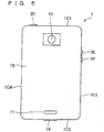
Figure 5 illustrates a rear view of the smartphone according to an embodiment. -
Figure 6 illustrates a block diagram of the smartphone according to an embodiment. -
Figure 7 illustrates a flowchart showing an example of control performed by the smartphone according to an embodiment. -
Figure 8 illustrates a schematic diagram showing an example of display of the smartphone according to an embodiment. -
Figure 9 illustrates a schematic diagram showing an example of display of the smartphone according to an embodiment. - Embodiments will be described in detail with reference to the drawings. In the following, smartphones will be described as examples of portable electronic devices.
- With reference to
Figure 1 , the overall configuration of acontrol system 100 including asmartphone 1 as a portable electronic device according to an embodiment will be described. Thecontrol system 100 includes aroadside device 110 and asmartphone 1. AlthoughFigure 1 shows sixroadside devices 110 and onesmartphone 1, thecontrol system 100 may include one ormore roadside devices 110 and one ormore smartphones 1, and the numbers of the devices and the smartphones are not limited. - In
Figure 1 , two roads intersect at an intersection having a traffic signal. A crosswalk is located at the intersection. - With reference to
Figure 1 , the overall configuration of theroadside device 100 will be described. Theroadside device 110 wirelessly outputs identification information of the self-device. The identification information of the self-device is information for identifying eachroadside device 110, for example, information indicating an identification number. Theroadside device 110 may wirelessly output road information including, for example, signal information, congestion information, and regulation information, along with the identification information of the self-device. Theroadside device 110 includes a communication unit 111, astorage 112, and acontroller 113. - The communication unit 111 communicates by radio. The communication unit 111 supports a wireless communication standard including Worldwide Interoperability for Microwave Access (WiMAX), IEEE 802.11 (including a, b, n, p), Bluetooth (registered trademark), Infrared Data Association (IrDA), Near Field Communication (NFC), and so forth. The communication unit 111 may also support a cellular phone communication standard such as 2G (generation), 3G (generation), and 4G (generation) including Long Term Evolution (LTE), Wideband Code Division Multiple Access (W-CDMA), CDMA2000, Personal Digital Cellular (PDC), Global System for Mobile Communications (GSM) (registered trademark), Personal Handy-phone System (PHS), and so forth. The communication unit 111 supports one or more of the communication standards described above. The communication unit 111 may support wired communication such as Ethernet (registered trademark), fiber channel, and so forth, for example.
- The communication unit 111 communicates with
other roadside devices 110 and traffic lights. The communication unit 111 communicates with a communication device within a predetermined distance by short-range wireless communication, for example, a communication device mounted on a vehicle and thesmartphone 1, and transmits and receives data. In one embodiment, the communication unit 111 communicates with thesmartphone 1, and transmits and receives data including the identification information of theroadside device 110 and the road information. - The
storage 112 stores programs and data. Thestorage 112 is also used as a work area for temporarily storing the processing result of thecontroller 113. Thestorage 112 may include any non-transitory storage medium such as a semiconductor storage medium and a magnetic storage medium. The non-transitory storage medium includes, for example, an optical disk such as CD (registered trademark), DVD (registered trademark), Blu-ray (registered trademark), a magneto optical disk, a magnetic storage medium, a memory card, a solid state storage medium, but it is not limited thereto. Thestorage 112 may include a plurality of types of storage media. Thestorage 112 may include a combination of a portable storage medium such as a memory card, an optical disk, or a magneto-optical disk and a reading device of a storage medium. Thestorage 112 may include a storage device used as a temporary storage area such as a Random Access Memory (RAM). - The program to be stored in the
storage 112 includes a program that establishes communication between the communication device within a predetermined distance from theroadside device 110 and the communication unit 111 and controls transmission and reception of data. The data to be stored in thestorage 112 includes, for example, data to be transmitted to another communication device such as identification information of theroadside device 110. - The
controller 113 includes an arithmetic processing unit. The arithmetic processing unit includes, but not limited to, a Central Processing Unit (CPU), a System-on-a-Chip (SoC), a Micro Control Unit (MCU), and a Field-Programmable Gate Array (FPGA). Thecontroller 113 integrally controls the operation of theroadside device 110 to realize various functions. - Specifically, the
controller 113 executes an instruction included in the program stored in thestorage 112 while referring to the data stored in thestorage 112 as necessary. And, thecontroller 113 controls the function unit in accordance with the data and the instruction, thereby realizing various functions. Thecontroller 113 can also be said to be a control circuit. Thecontroller 113 includes at least one processor to provide control and processing capabilities to execute various functions, as described in further detail below. - According to embodiments, the at least one processor may be implemented as a single integrated circuit (IC) or as a plurality of communicably coupled integrated circuits IC and/or discrete circuits. The at least one processor can be implemented in accordance with various known techniques.
- In one embodiment, the processor includes one or more circuits or units configured to perform one or more data calculation procedures or processes, for example, by executing instructions stored in an associated memory. In other embodiments, the processor may be firmware (for example, a discreet logic component) configured to perform one or more data calculation procedures or processes.
- According to embodiments, the processor may be one or more of a processor, a controller, a microprocessor, a microcontroller, an Application-Specific Integrated Circuit (ASIC), a digital signal processor, a programmable logic device, a field programmable gate array, or any combination of the devices or configurations or combinations of other known devices and configurations may be included to perform the functions described below.
- The overall configuration of the
smartphone 1 according to an embodiment will be described with reference toFigures 3 to 5 . Thesmartphone 1 has ahousing 20. Thehousing 20 has afront face 1A, aback face 1B, and side faces 1C1 to 1C4. Thefront face 1A represents the front face of thehousing 20. Theback face 1B represents the back face of thehousing 20. The side faces 1C1 to 1C4 are side faces connecting thefront face 1A and theback face 1B. In the following, the side faces 1C1 to 1C4 may be collectively referred to as side face 1C without indicating any particular side face. The configuration of thesmartphone 1 shown inFigures 3 to 5 is an example, and may be appropriately changed within a scope not to impair the gist of the present disclosure. - The
smartphone 1 has a touch screen display (display) 2,buttons 3A to 3C, anilluminance sensor 4, aproximity sensor 5, areceiver 7, amicrophone 8, and acamera 12 in thefront face 1A. Thesmartphone 1 has aspeaker 11 and acamera 13 in theback face 1B. Thesmartphone 1 hasbuttons 3D to 3F and aconnector 14 in the side face 1C. In the following, thebuttons 3A to 3F may be collectively referred to asbutton 3 without indicating any particular button. - The
touch screen display 2 has adisplay 2A and atouch screen 2B In an example ofFigure 3 , thedisplay 2A and thetouch screen 2B each have a substantially rectangular shape, however, the shapes of thedisplay 2A and thetouch screen 2B are not limited thereto. - Each of the
display 2A and thetouch screen 2B may have any shape such as a square shape or a circular shape. In the example ofFigure 3 , although thedisplay 2A and thetouch screen 2B overlap each other, the positions of thedisplay 2A and thetouch screen 2B are not limited thereto. For example, thedisplay 2A and thetouch screen 2B may be positioned side by side or separated from each other. Although in the example ofFigure 3 , the long side of thedisplay 2A is along the long side of thetouch screen 2B and the short side of thedisplay 2A is along the short side of thetouch screen 2B, the overlapping manner of thedisplay 2A and thetouch screen 2B is not limited thereto. When thedisplay 2A and thetouch screen 2B overlap each other, for example, one or a plurality of sides of thedisplay 2A may not be along either side of thetouch screen 2B. - The
display 2A includes a display device such as a Liquid Crystal Display (LCD), an Organic Electro-Luminescence Display (OELD), or an Inorganic Electro-Luminescence Display (IELD). Thedisplay 2A displays objects such as characters, images, symbols, graphics, and the like. - The
touch screen 2B detects contact of an operator, such as a finger, a pen, a stylus pen, or the like, with respect to thetouch screen 2B. Thetouch screen 2B can detect a position where an operator, such as a plurality of fingers, a pen, a stylus pen, or the like touches thetouch screen 2B. The detection method of thetouch screen 2B may include an arbitrary method such as an electrostatic capacitance method, a resistive film method, a surface acoustic wave method (or an ultrasonic method), an infrared method, an electromagnetic induction method, and a load detection method. In the following description, for simplicity of explanation, it is assumed that a user touches thetouch screen 2B using a finger in order to operate thesmartphone 1. - The
smartphone 1 determines operation (gesture) to be performed on thetouch screen 2B based on at least one of a contact detected by thetouch screen 2B, a position where a contact is detected, a change in a position where a contact is detected, a time interval in which a contact is detected, and a number of times a contact is detected. Operations performed on thetouch screen 2B include, but not limited to, touch, long touch, release, swipe, tap, double tap, long tap, drag, flick, pinch in, and pinch out. - The functional configuration of the
smartphone 1 according to an embodiment will be described with reference toFigures 6 . The configuration of thesmartphone 1 shown inFigure 6 is an example, and may be appropriately changed within a scope not to impair the gist of the present disclosure. - The
smartphone 1 includes atouch screen display 2, abutton 3, anilluminance sensor 4, aproximity sensor 5, a communication unit (information acquisition unit, transmitter) 6, areceiver 7, amicrophone 8, a storage (storage) 9, acontroller 10, aspeaker 11, acamera 12 and acamera 13, aconnector 14, anacceleration sensor 15, adirection sensor 16, and agyroscope 17. - The
touch screen display 2 has, as described above, adisplay 2A and atouch screen 2B Thedisplay 2A displays objects such as characters, images, symbols, graphics, and the like. Thetouch screen 2B detects contact of an operator. Thetouch screen 2B outputs information on the detected contact to thecontroller 10. - The
button 3 is operated by a user. Thebutton 3 includesbuttons 3A to 3F. Thecontroller 10 can detect an operation on thebutton 3 by cooperating with thebutton 3. Operations onbutton 3 include, but not limited to, click, double click, triple click, push, and multi push, for example. - The
buttons 3A to 3C represent, for example, a home button, a back button or a menu button. Thebutton 3D represents, for example, a power on-off button of thesmartphone 1. Thebutton 3D may also serve as a sleep/sleep-release button. For example, thebuttons - The
illuminance sensor 4 can detect the illuminance of the ambient light of thesmartphone 1. Illuminance indicates light intensity, brightness, or luminance. Theilluminance sensor 4 is used, for example, for adjusting the luminance of thedisplay 2A. Theproximity sensor 5 can detect the presence of a neighboring object in a noncontact manner. Theproximity sensor 5 detects the presence of an object based on a change in a magnetic field, a change in a feedback time of a reflected wave of an ultrasonic wave, or the like. Theproximity sensor 5 detects, for example, that thetouch screen display 2 has been being approached toward the face. Theilluminance sensor 4 and theproximity sensor 5 may be configured as one sensor. Theilluminance sensor 4 may be used as a proximity sensor. - The
communication unit 6 can communicate wirelessly. In one embodiment, thecommunication unit 6 has a function of at least a short-range wireless communication. The communication method to be supported by thecommunication unit 6 is a wireless communication standard. Thecommunication unit 6 supports communication standards of cellular phones such as 2G, 3G, 4G, and 5G. The cellular phone communication standards include, for example, LTE, W-CDMA, CDMA 2000, PDC, GSM (registered trademark) and PHS. Thecommunication unit 6 may support wireless communication standards including WiMAX, IEEE 802.11, Bluetooth (registered trademark), IrDA, NFC, and the like, for example. Thecommunication unit 6 may support one or more of the communication standards described above. - The
communication unit 6 may support wired communication. The wired communication includes, for example, Ethernet (registered trademark), fiber channel, and so forth. - In one embodiment, the
communication unit 6 supports a communication standard for enabling communication with theroadside device 110 arranged by the road. For example, thesmartphone 1 acquires information on theroadside device 110 by communicating with theroadside device 110 via thecommunication unit 6. In one embodiment, thecommunication unit 6 may support a communication standard for enabling communication with a communication device mounted on a vehicle. For example, thesmartphone 1 acquires information on the vehicle by communicating with the vehicle via thecommunication unit 6. - The
receiver 7 and thespeaker 11 are configured as sound output units. Thereceiver 7 and thespeaker 11 can output a sound signal transmitted from thecontroller 10 as a sound. Thereceiver 7 is used, for example, to output the sound of the opposite party during a call. Thespeaker 11 is used, for example, to output the sound of the ringtone and a piece of music. Either thereceiver 7 or thespeaker 11 may also serve as the function of the other. - The
microphone 8 is configured as a sound input unit. Themicrophone 8 can convert the voice or the like of the user into a sound signal and transmit it to thecontroller 10. - The
acceleration sensor 15 can detect information indicating the direction and magnitude of the acceleration acting on thesmartphone 1. Thedirection sensor 16 can detect information indicating the direction of the terrestrial magnetism. Thegyroscope 17 can detect information on the angle and angular velocity of thesmartphone 1. The detection results of theacceleration sensor 15, thedirection sensor 16 and thegyroscope 17 are used in combination, for example, in order to detect changes in the position and the posture of thesmartphone 1. - In an example shown in
Figure 6 , thesmartphone 1 has three types of sensors for detecting the position and the posture, however, thesmartphone 1 may not include some sensors among the three sensors. Alternatively, thesmartphone 1 may include other types of sensors for detecting at least one of the position and the posture. - Controlling the other components of the
smartphone 1 enables thecontroller 10 to integrally manage the operation of thesmartphone 1. Thecontroller 10 can also be said to be a control circuit. Thecontroller 10 includes at least one processor to provide control and processing capabilities to execute various functions, as described in further detail below. - According to embodiments, the at least one processor may be implemented as a single integrated circuit (IC) or as a plurality of communicably coupled integrated circuits IC and/or discrete circuits. The at least one processor can be implemented in accordance with various known techniques.
- In one embodiment, the processor includes one or more circuits or units configured to perform one or more data calculation procedures or processes, for example, by executing instructions stored in an associated memory. In other embodiments, the processor may be firmware (for example, a discreet logic component) configured to perform one or more data calculation procedures or processes.
- According to embodiments, the processor may be one or more of a processor, a controller, a microprocessor, a microcontroller, an Application-Specific Integrated Circuit (ASIC), a digital signal processor, a programmable logic device, a field programmable gate array, or any combination of the devices or configurations or combinations of other known devices and configurations may be included to perform the functions described below.
- The
storage 9 stores programs and data. Thestorage 9 is also used as a work area for temporarily storing the processing result of thecontroller 10. Thestorage 9 may include any non-transitory storage medium such as a semiconductor storage medium and a magnetic storage medium. Thestorage 9 may include a plurality of types of storage media. Thestorage 9 may include a combination of a portable storage medium such as a memory card, an optical disk, or a magneto-optical disk and a reading device of a storage medium. Thestorage 9 may include a storage device used as a temporary storage area such as a RAM. - Part or all of the programs and data stored in the
storage 9 may be downloaded from another device by communication by thecommunication unit 6. Part or all of the programs and data stored in thestorage 9 may be stored in a non-transitory storage medium readable by a reading device included in thestorage 9. Part or all of the programs and data stored in thestorage 9 may be stored in a non-transitory storage medium readable by a reading device connected to the connector (not illustrated). - The program to be stored in the
storage 9 includes an application program (hereinafter referred to as an application) executed in the foreground or the background and a control program for supporting the operation of the application. The application causes thecontroller 10 to execute, for example, a process of displaying a screen on thedisplay 2A and a process corresponding to a gesture detected via thetouch screen 2B. The control program includes, for example, an Operating System (OS). - The
storage 9 stores, for example, acontrol program 9A, amail application 9B, a movementhistory display application 9C, roadsidedevice position data 9D,map data 9E,movement state data 9F,movement history data 9G, and settingdata 9Z. - The
mail application 9B provides an e-mail function for creating, sending, receiving, displaying, etc. the e-mail. - The movement
history display application 9C provides a function of displaying a movement history (movement log) of a user carrying the smartphone 1 (hereinafter simply referred to as a user). By executing the movementhistory display application 9C, thecontroller 10 executes the operation described below. - The
controller 10 causes thetouch screen display 2 to display the movement history of the user in chronological order. Alternatively, thecontroller 10 may cause thetouch screen display 2 to display the movement history of the user on the map. Thecontroller 10 may also cause thetouch screen display 2 to display, for example, a line connecting position information of thesmartphone 1 along a time series on the map as a movement route. Alternatively, if the position information of thesmartphone 1 satisfies the predetermined condition, thecontroller 10 may cause thetouch screen display 2 to display the position information of thesmartphone 1 that satisfies the predetermined condition in a manner different from the other position information of thesmartphone 1. Here, for example, thecontroller 10 may determine that the predetermined condition is satisfied if the position information of thesmartphone 1 is out of a predetermined range, so that the user is determined to be in an unusual place. In this case, as the predetermined range, a range in which the user usually acts is adopted. Alternatively, thecontroller 10 may determine that the predetermined condition is satisfied, for example, if the position information is within a predetermined range, so that the user is passing through a road with a high traffic volume or a high degree of danger. In this case, as the predetermined range, a road with a large traffic volume or a road with many accidents is adoptable. - In the roadside
device position data 9D, the identification information of theroadside device 110 and the position information are previously stored in association with each other. More specifically, for each identification information of theroadside device 110, the roadsidedevice position data 9D stores the installation position of theroadside device 110 as position information indicated by latitude and longitude. - The
map data 9E stores map information. - The
movement state data 9F includes information used for estimating the movement state of the user. Themovement state data 9F stores a correspondence relationship between the detection result of the sensor and the movement state detected in advance by a test, a simulation, and so forth. In one embodiment, themovement state data 9F stores reference data for determining whether or not the user is walking. - The
movement history data 9G stores the position information of thesmartphone 1 at the time of acquiring information from theroadside device 110 and the movement state of the user along with the time (including date) when the information is acquired from theroadside device 110. - The setting
data 9Z includes information on various settings related to the operation of thesmartphone 1. The settingdata 9Z stores the usual action range of the user as a range indicated by, for example, latitude and longitude. The settingdata 9Z stores transmission destination information of a transmission destination of the user's position information. In one embodiment, the transmission destination information includes, for example, a mail address of an offspring of an elderly person when the user of thesmartphone 1 is an elderly person, and a mail address of a parent of a small child when the user of thesmartphone 1 is a small child. - The
control program 9A provides functions related to various controls for operating thesmartphone 1. Thecontrol program 9A provides a function of realizing a call by, for example, controlling thecommunication unit 6, thereceiver 7, themicrophone 8, and so forth. The function provided by thecontrol program 9A includes a function of controlling information to be displayed on thedisplay 2A. The functions provided by thecontrol program 9A include a function of performing various controls such as changing information displayed on thedisplay 2A according to an operation detected via thetouch screen 2B. The functions provided by thecontrol program 9A may be used in combination with functions provided by other programs such as themail application 9B. - The
controller 10 configured to execute thecontrol program 9A can perform the following operations. Thecontroller 10 determines the movement state of the user. The movement state includes a stopped state in which the user is stopped, a walking state in which the user is walking, a running state in which the user is running, and a riding state in which the user is riding in the automobile or the train. Thecontroller 10 measures vibration and movement acting on thesmartphone 1 based on the direction and magnitude of the acceleration acquired from theacceleration sensor 15. Thecontroller 10 refers to themovement state data 9F and determines the movement state from the measurement results of vibration and movement. As a substitute for or as a supplement for theacceleration sensor 15, thecontroller 10 may determine the movement state by using at least one of thedirection sensor 16, thegyroscope 17, themicrophone 8, thecamera 12, and thecamera 13. - By executing the
control program 9A, thecontroller 10 acquires the position information of theroadside device 110 from the roadsidedevice position data 9D based on the information acquired from theroadside device 110, and can store themovement history data 9G in thestorage 9, which includes the position information of theroadside device 100 as the position information of thesmartphone 1 at the time of acquiring information from theroadside device 110. - By executing the
control program 9A, thecontroller 10 can cause thecommunication unit 6 to transmit the position information of thesmartphone 1 to the transmission destination corresponding to the transmission destination information if the position information of thesmartphone 1 satisfies the predetermined condition. - The
controller 10 includes an arithmetic processing unit. The arithmetic processing unit includes, but not limited to, for example, a CPU, a SoC, an MCU, and an FPGA. Thecontroller 10 integrally controls the operation of thesmartphone 1 to realize various functions. - Specifically, the
controller 10 executes an instruction included in the program stored in thestorage 9 while referring to the data stored in thestorage 9 as necessary. And, thecontroller 10 controls the function unit in accordance with the data and the instruction, thereby realizing various functions. The function unit may include, but not limited to, at least one of thedisplay 2A, thecommunication unit 6, thereceiver 7, and thespeaker 11, for example. Thecontroller 10 may change the control in accordance with the detection result of the detection unit. The detection unit may include, but not limited to, for example, at least one of thetouch screen 2B, thebutton 3, theilluminance sensor 4, theproximity sensor 5, themicrophone 8, thecamera 12, thecamera 13, theacceleration sensor 15, thedirection sensor 16 and thegyroscope 17. - The
controller 10 detects an operation on thesmartphone 1. Specifically, thecontroller 10 cooperates with thetouch screen 2B to detect an operation on thetouch screen 2B (touch screen display 2). - For example, the
controller 10 executes various controls such as changing information displayed on thedisplay 2A according to an operation detected via thetouch screen 2B, by executing thecontrol program 9A. - The
camera 12 is a front camera that photographs an object facing thefront face 1A.
Thecamera 13 is a rear camera that photographs an object facing theback face 1B. - The
connector 14 is a terminal to which another device is connected. Theconnector 14 may be a general-purpose terminal such as Universal Serial Bus (USB), High-Definition Multimedia Interface (registered trademark) (HDMI), Light Peak (Thunderbolt (registered trademark)), earphone microphone connector. Theconnector 14 may be a dedicated terminal such as a Dock connector. Devices connected to theconnector 14 include, but not limited to, an external storage, a speaker, and a communication device, for example. - Next, with reference to
Figure 7 , a control method of thesmartphone 1 and the action thereof will be described. - The
smartphone 1 can execute the processing procedure shown inFigure 7 by thecontroller 10 executing thecontrol program 9A stored in thestorage 9. Also, thecontroller 10 may execute processing procedure of other functions in parallel with the processing procedure shown inFigure 7 . - The
controller 10 acquires information from the roadside device 110 (step S11). More specifically, if the distance between thesmartphone 1 and theroadside device 110 is equal to or less than a predetermined distance, thecontroller 10 receives the information that theroadside device 110 wirelessly outputs via thecommunication unit 6. In other words, if thecontroller 10 detects thecommunicable roadside device 110 based on the sensor detection result, thecontroller 10 receives the information that theroadside device 110 wirelessly transmits. Communicable indicates that a signal capable of transmitting and receiving data arrives. Thecontroller 10 may determine whether or not the distance between thesmartphone 1 and theroadside device 110 is equal to or less than a predetermined distance, based on whether or not the received signal strength of the wireless signal output by theroadside device 110 is equal to or greater than a predetermined value, for example. Specifically, thecontroller 10 determines that the distance between thesmartphone 1 and theroadside device 110 is equal to or less than the predetermined distance if the received signal strength of the radio reception wireless signal output from theroadside device 110 is equal to or greater than a predetermined value. - The
controller 10 acquires position information (step S12). More specifically, from the roadsidedevice position data 9D, thecontroller 10 acquires position information corresponding to the identification information of theroadside device 110 included in the acquired information. - The
controller 10 acquires the movement state of the user (step S13). More specifically, thecontroller 10 measures vibration and movement acting on thesmartphone 1 based on the direction and magnitude of the acceleration acquired from theacceleration sensor 15. And, thecontroller 10 refers to themovement state data 9F and determines the movement state from the measurement results of vibration and movement. - The
controller 10 stores the position information (step S14). More specifically, thecontroller 10 stores, as themovement history data 9G, the time when the information is acquired from theroadside device 110, the position information acquired in step S12, and the movement state determined in step S13. - The
controller 10 determines whether or not the predetermined condition is satisfied (step S15). More specifically, for example, if the position information acquired in step S12 deviates from the usual action range that is a predetermined range registered in advance, Yes is determined in step S15. Information indicating this action range is included in the settingdata 9D. - Alternatively, if the position information indicates to be located on the dangerous road, the
controller 10 may determine Yes in step S15. As a dangerous road, for example, a road with a large traffic volume can be adopted. For example, if the information acquired in step S11 includes road information indicating that the traffic volume is high, Yes may be determined in step S15. Whether the traffic volume is high may be determined based on whether the traffic volume included in the road information is equal to or higher than a predetermined amount or whether the road is congested from congestion information included in the road information. - If determining that the predetermined condition is satisfied (Yes in step S15), the
controller 10 transmits the position information (step S16). More specifically, thecontroller 10 transmits the position information of the smartphone 1 (the user carrying the self-device) to the transmission destination indicated by the transmission destination information registered in advance with themail application 9B or the like. Thecontroller 10 may convert the position information into character information such as an address specified by latitude and longitude based on themap data 9E, character information such as a road name and intersection name, an image of map information indicating a point specified by latitude and longitude based on themap data 9E, or a Uniform Resource Locator (URL) indicating the storage position of the map information, and transmit the converted position information. - If the
controller 10 determines that the predetermined condition is not satisfied (No in step S15), thecontroller 10 ends the process. - The
smartphone 1 can implement the function of displaying the movement history by executing the movementhistory display application 9C stored in thestorage 9 by thecontroller 10. - More specifically, upon activation of the movement
history display application 9C, thecontroller 10 causes thetouch screen display 2 to display the position information of the user along with the time and movement state based on themovement history data 9G stored in thestorage 9. For example, as shown inFigure 8 , thecontroller 10 displays themovement history data 9G in chronological order. - As the user moves on the road, the
smartphone 1 sequentially communicates with a plurality ofroadside devices 110 provided along the road. For example, as the user moves on the road and the user enters a first communicable range of afirst roadside device 110 at the time t1, thesmartphone 1 acquires an installation position of thefirst roadside device 110 as the position of the user, as described above. During a period in which the user is within the first communicable range, thesmartphone 1 may continue to acquire the installation position of thefirst roadside device 110 as the position of the user. When the user leaves the first communicable range at the time t [m], thesmartphone 1 cannot communicate with thefirst roadside device 110, so acquisition of the position information of the user based on thefirst roadside device 110 is not performed. And, as the user further moves on the road and enters a second communicable range of thesecond roadside device 110 at the time t [m+n], thesmartphone 1 acquires an installation position of asecond roadside device 110 as the position of the user. During a period in which the user is within the second communicable range, thesmartphone 1 may continue to acquire the installation position of thesecond roadside device 110 as the position of the user. When the user leaves the second communicable range at the time t [m+n+p], thesmartphone 1 cannot communicate with thesecond roadside device 110, so acquisition of the position information of the user based on thesecond roadside device 110 is not performed. - In this case, in the
movement history data 9G, for example, the installation position of thefirst roadside device 110 is included at each of the times t [1] to t [m], and the installation position of thesecond roadside device 110 is included at each of the times t [m+n] to t [m+n+p] as the position of the user. - Thereafter, every time the user enters the communicable range of another
roadside device 110, the position information of the user is added to themovement history data 9G along with the time. - In an example of
Figure 8 , a plurality of times are shown aligned along in the vertical direction on the left side in the screen of thetouch screen display 2, and in the right side region of the time region, rectangular blocks having two different types of widths are shown. For example, a wide block indicates a period in which the user is located within the wireless communication range of theroadside device 110, and a narrow block indicates a period in which the user is located outside the wireless communication ranges of all theroadside devices 110. Each time is shown at a position corresponding to each of the upper side and the lower side of a wide block. For example,Figure 8 shows a wide block in which the time "14:23" and the time "14:25" are appended corresponding to the upper side and the lower side, respectively. The block indicates that the user has entered the communicable range of theroadside device 110 at the time "14:23" and at the time "14:25" that the user has gone out of the communicable range of theroadside device 110. As described above, it can be said that the block ofFigure 8 indicates the position information of the user. - Further, in
Figure 8 , the position information of thecorresponding roadside device 110 is displayed as "A" to "E", respectively, adjacent to the corresponding wide rectangular blocks. "A "to" E "may be, for example, an address or an intersection name where theroadside devices 110 are located, respectively, and so forth. Also, the denotation "A" to "E" of the position information may be shown inside the corresponding wide rectangular blocks. Alternatively, thecontroller 10 does not display "A" to "E" inFigure 8 , and if thetouch screen 2B detects an operation on the wide block, the position information corresponding to the wide block to which the operation is performed may be displayed. - The
controller 10 may cause theposition information 201 determined to satisfy the predetermined condition in step S15 to be displayed in a manner different from other position information that is not determined to satisfy the predetermined condition. InFigure 8 , theposition information 201 determined to satisfy the predetermined condition is displayed while, for example, changing the color or blinking with other position information not determined to satisfy the predetermined condition. - In this case, the
controller 10 stores the information of the determination result as to whether or not the predetermined condition is satisfied in themovement history data 9G and stores thereof in thestorage 112. As a specific operation, if thecontroller 10 receives the information from theroadside device 110, thecontroller 10 acquires the position information of theroadside device 110 based on the information, and determines whether or not the predetermined condition is satisfied based on the information. And, thecontroller 10 associates the time, the position information, and the determination result with each other in themovement history data 9G, and stores themovement history data 9G in thestorage 112. Thecontroller 10 causes thetouch screen display 2 to display the position information in a manner according to the determination result included in themovement history data 9G. - Then, if the
controller 10 detects that the user has performed the operation of selecting theposition information 201 satisfying the predetermined condition on thetouch screen 2B, as shown inFigure 9 , thecontroller 10 displays theposition information 201 satisfying the predetermined condition on the map. - According to above embodiments, the
smartphone 1 can acquire the position information of thesmartphone 1 at the time of acquiring information from theroadside device 110 based on the information acquired from theroadside device 110. Therefore, thesmartphone 1 can suppress the power consumption as compared with the case where the position information is acquired by a signal receiver of a positioning satellite such as a GPS receiver. That is, unlike the embodiments, for example, when the portable electronic device (smartphone 1) frequently acquires the position information by the GPS receiver in order to confirm the position of the self-device, the power consumption of the portable electronic device becomes large. On the other hand, in the embodiments, the position information (predetermined position information) of theroadside device 110 is adopted as the position information of thesmartphone 1 based on the information acquired from theroadside device 110. Therefore, the position information of thesmartphone 1 is readily acquired and the power consumption is suppressed. - Moreover, a plurality of
roadside devices 110 are regularly arranged along roads, intersections, and the like. Therefore, by acquiring the position information of thesmartphone 1 based on the information acquired from theroadside device 110, the traveling route of the user moving on the road can be accurately acquired. Therefore, according to the embodiments, thesmartphone 1 can acquire the position information of thesmartphone 1 with high accuracy as well as the case where the position information is acquired by a signal receiver of a positioning satellite such as a GPS receiver. - Meanwhile, for example, the case where the position information of the
smartphone 1 is acquired based on the information received from the public wireless LAN will be described. While many public wireless LANs are installed in urban areas, many places are not installed in residential areas. Therefore, for example, when moving in a residential area, possibilities are that information cannot be received from the public wireless LAN and position information of thesmartphone 1 cannot be acquired. Thus, for example, when acquiring the position information of thesmartphone 1 based on the information received from the public wireless LAN, possibilities are that the position information of thesmartphone 1 may not be acquired depending on the location, depending on the installation condition of the public wireless LAN. However, according to the embodiments, thesmartphone 1 acquires the position information of thesmartphone 1 based on the information from theroadside device 110 regularly arranged along the road or at an intersection or the like, therefore the position of thesmartphone 1 can be acquired more accurately. - The
smartphone 1 can acquire the road information of the traveling route along with the identification information from theroadside device 110. Accordingly, based on the road information acquired from theroadside device 110, for example, thesmartphone 1 determines a state where the user carrying the self-device is passing through a road with a high traffic volume, a high degree of danger, or staying in the unusual action range, and can transmit the position information to the previously registered destination. As a result, thesmartphone 1 determines, for example, that an elderly person or a small child is traveling on a road with a high degree of danger or is staying in the unusual action range, and can notify a parent and so forth. The parent who received the notification can warn the elderly person or the small child as necessary. - The
controller 10 of thesmartphone 1 determines that theposition information 201 that is determined that the user is passing through a road with a high degree of danger or is staying in the unusual place is displayed in a manner different from the other position information. As a result, thesmartphone 1 displays whether the user is not passing through a high-risk road or not passing through the unusual place in an easy-to-see manner. - Embodiments disclosed in the application can be modified without departing from the spirit and scope of the invention. Further, embodiments disclosed in the application and modifications thereof can be appropriately combined. For example, the above embodiments may be modified as follows.
- For example, each program shown in
Figure 6 may be divided into a plurality of modules, or may be combined with other programs. - Although a smartphone has been described as an example of a portable electronic device, the device according to the appended claims is not limited to a smartphone. The device according to the appended claims may be a portable electronic device other than a smartphone. Mobile electronic devices include, but not limited to, mobile phones, tablets, portable personal computers, digital cameras, media players, electronic book readers, navigators, and game consoles, for example.
- The
storage 9 may store the identification information of theroadside device 110 located within the action range as the usual action range of the user. In other words, the identification information of theroadside device 110 existing within the range in which the user usually acts is stored in thestorage 9. - If the
controller 10 determines that the identification information of theroadside device 110 from which the information is acquired does not coincide with any of the identification information stored in thestorage 9, thecontroller 10 determines that the user has deviated from the usual action range. In this case, thecontroller 10 transmits the position information and the fact that the user has deviated from the usual action range to the transmission destination stored in thestorage 9 by themail application 9B or the like. In this way, the protector or the supervisor of the destination can watch over the user more reliably. If the user deviates from the usual action range, thesmartphone 1 can immediately notify the transmission destination, so that the parent or guardian of the transmission destination or the like can watch the user more reliably. - In an example of
Figure 6 , although thesmartphone 1 transmits the position information if the predetermined condition is satisfied, the position information may be transmitted regardless of whether or not the predetermined condition is satisfied. - Although the
roadside device 110 transmits information including the identification information of the self-device and not including the position information indicated by the latitude and longitude of the self-device, theroadside device 110 may also transmit information including the position information of the self-device. In this case, thesmartphone 1 may store, in thestorage 9, the position information acquired from theroadside device 110. - Embodiments have been described for clearly disclosing portable electronic devices. However, the portable electronic device should not be limited to the above-described embodiments, and should be configured to embody the configuration in which all modifications and alternatives that can be created by those skilled in the art within the scope of the basic matter described in the specification are applicable.
-
- 1
- smartphone (portable electronic device)
- 2
- touch screen display (display)
- 2A
- display
- 2B
- touch screen
- 6
- communication unit (information acquisition unit, transmission unit)
- 9
- storage
- 9A
- control program
- 9B
- mail application
- 9C
- movement history display application
- 9D
- roadside device position data
- 9E
- map data
- 9F
- movement state data
- 9G
- movement history data
- 9Z
- setting data
- 10
- controller
- 100
- control system
- 110
- roadside device
- 111
- communication unit
- 112
- storage
- 113
- controller
Claims (10)
- A portable electronic device, comprising:an information acquisition unit configured to acquire information from a roadside device;a storage; anda controller configured to acquire position information of the roadside device based on the information acquired by the information acquisition unit, and cause the storage to store the acquired position information of the road side device as position information of the portable electronic device at a time of acquiring the information.
- The portable electronic device according to claim 1, wherein
the controller is configured to acquire position information indicating an installation position of the roadside device as the position information of the roadside device. - The portable electronic device according to claim 1 or 2, further comprising
a display, wherein
the controller is configured to display the position information of the portable electronic device on the display in chronological order. - The portable electronic device according to claim 1 or 2, further comprising
a display, wherein
the controller is configured to cause the display to display a map, and cause the display to display the position information of the portable electronic device on the map. - The portable electronic device according to claim 3 or 4, wherein,
when the position information of the portable electronic device satisfies a predetermined condition, the controller is configured to cause the display to display the position information of the portable electronic device satisfying the predetermined condition in a manner different from an other position information of the portable electronic device. - The portable electronic device according to any one of claims 1 to 5, further comprising
a transmitter,
wherein the storage is configured to store transmission destination information related to a transmission destination, and
wherein the controller is configured to cause the transmitter to transmit the position information of the portable electronic device to the transmission destination corresponding to the transmission destination information. - The portable electronic device according to claim 6, wherein,
when the position information of the portable electronic device satisfies a predetermined condition, the controller is configured to cause the transmitter to transmit the position information of the portable electronic device satisfying the predetermined condition to the transmission destination corresponding to the transmission destination information. - The portable electronic device according to claim 5 or 7, wherein,
when the controller determines that the position information of the portable electronic device is out of a predetermined range, or that the position information of the portable electronic device indicates to be located on a dangerous road, the controller is configured to determine that the predetermined condition is satisfied. - A method of controlling a portable electronic device for controlling the portable electronic device including a storage, the method comprising the steps of:acquiring information from a roadside device;acquiring position information of the roadside device based on the acquired information; andcausing the storage to store the acquired position information of the road side device as position information of the portable electronic device at a time of acquiring the information.
- A control program for portable electronic device, the program controlling the portable electronic device including a storage to execute the steps of;
acquiring information from a roadside device;
acquiring position information of the roadside device based on the acquired information; and
causing the storage to store the acquired position information of the road side device as position information of the portable electronic device at a time of acquiring the information.
Applications Claiming Priority (2)
| Application Number | Priority Date | Filing Date | Title |
|---|---|---|---|
| JP2016103686A JP6334605B2 (en) | 2016-05-24 | 2016-05-24 | Portable electronic device, portable electronic device control method, and portable electronic device control program |
| PCT/JP2017/019142 WO2017204199A1 (en) | 2016-05-24 | 2017-05-23 | Portable electronic device, method for controlling portable electronic device, and control program for portable electronic device |
Publications (3)
| Publication Number | Publication Date |
|---|---|
| EP3444567A1 true EP3444567A1 (en) | 2019-02-20 |
| EP3444567A4 EP3444567A4 (en) | 2019-05-01 |
| EP3444567B1 EP3444567B1 (en) | 2020-11-04 |
Family
ID=60412368
Family Applications (1)
| Application Number | Title | Priority Date | Filing Date |
|---|---|---|---|
| EP17802785.0A Active EP3444567B1 (en) | 2016-05-24 | 2017-05-23 | Portable electronic device, method for controlling portable electronic device, and control program for portable electronic device |
Country Status (4)
| Country | Link |
|---|---|
| US (1) | US10575135B2 (en) |
| EP (1) | EP3444567B1 (en) |
| JP (1) | JP6334605B2 (en) |
| WO (1) | WO2017204199A1 (en) |
Families Citing this family (3)
| Publication number | Priority date | Publication date | Assignee | Title |
|---|---|---|---|---|
| JP2852459B2 (en) | 1990-07-02 | 1999-02-03 | 戸田工業株式会社 | Method for producing spindle-shaped iron-based metal magnetic particle powder |
| JP2852460B2 (en) | 1990-07-02 | 1999-02-03 | 戸田工業株式会社 | Method for producing spindle-shaped iron-based metal magnetic particle powder |
| JP7107068B2 (en) * | 2018-07-30 | 2022-07-27 | トヨタ自動車株式会社 | dispatch system |
Family Cites Families (16)
| Publication number | Priority date | Publication date | Assignee | Title |
|---|---|---|---|---|
| JPH11160085A (en) | 1997-11-25 | 1999-06-18 | Hitachi Eng Co Ltd | Position measurement method and system |
| JP2000180199A (en) * | 1998-12-21 | 2000-06-30 | Sharp Corp | Action history output device and computer-readable recording medium |
| JP2001099672A (en) | 1999-09-30 | 2001-04-13 | Tohoku Electric Power Co Inc | Positioning system |
| JP2003244739A (en) * | 2002-02-21 | 2003-08-29 | Sony Ericsson Mobilecommunications Japan Inc | Destination arrival guidance system, base station and mobile terminal |
| DE602004029908D1 (en) | 2003-09-01 | 2010-12-16 | Panasonic Corp | DEVICE AND METHOD FOR DISPLAYING THE POSITION OF A MOBILE OBJECT |
| JP4735179B2 (en) * | 2005-10-12 | 2011-07-27 | 株式会社デンソー | Vehicle control device |
| US8058987B1 (en) * | 2006-05-04 | 2011-11-15 | Skybitz, Inc. | Satellite aided location tracking with user interface |
| JP2008113184A (en) | 2006-10-30 | 2008-05-15 | Nec Corp | POSITION MONITORING SYSTEM, POSITION MONITORING DEVICE, POSITION MONITORING METHOD, AND MOBILE TERMINAL |
| JP2010009629A (en) * | 2009-10-15 | 2010-01-14 | Seiko Epson Corp | Location notification device |
| JP2012015714A (en) | 2010-06-30 | 2012-01-19 | Sanyo Electric Co Ltd | Terminal device |
| US9262915B2 (en) * | 2013-05-09 | 2016-02-16 | KERBspace, Inc | Intelligent urban communications portal and methods |
| JP6218544B2 (en) * | 2013-10-09 | 2017-10-25 | 日本電信電話株式会社 | Information collection and delivery system, information collection and delivery method, and information collection and delivery program |
| JP2015137979A (en) * | 2014-01-23 | 2015-07-30 | 日産自動車株式会社 | Component layout device and system, on-vehicle information terminal and server device |
| EP3142090A4 (en) * | 2014-05-07 | 2018-01-03 | Otta Inc. | Position information notification system |
| KR20170023085A (en) * | 2014-06-18 | 2017-03-02 | 센시티 시스템즈 아이엔씨. | Application framework for interactive light sensor networks |
| JP6330732B2 (en) * | 2015-06-02 | 2018-05-30 | 株式会社デンソー | Control device and support system |
-
2016
- 2016-05-24 JP JP2016103686A patent/JP6334605B2/en active Active
-
2017
- 2017-05-23 EP EP17802785.0A patent/EP3444567B1/en active Active
- 2017-05-23 WO PCT/JP2017/019142 patent/WO2017204199A1/en not_active Ceased
-
2018
- 2018-11-21 US US16/197,589 patent/US10575135B2/en active Active
Also Published As
| Publication number | Publication date |
|---|---|
| WO2017204199A1 (en) | 2017-11-30 |
| JP6334605B2 (en) | 2018-05-30 |
| EP3444567A4 (en) | 2019-05-01 |
| JP2017211250A (en) | 2017-11-30 |
| US20190098455A1 (en) | 2019-03-28 |
| EP3444567B1 (en) | 2020-11-04 |
| US10575135B2 (en) | 2020-02-25 |
Similar Documents
| Publication | Publication Date | Title |
|---|---|---|
| US11244553B2 (en) | Electronic device, control method, and non-transitory computer-readable medium | |
| US10609510B2 (en) | Mobile electronic apparatus, mobile electronic apparatus control method, a non-transitory computer readable recording medium, for providing warnings to a user of the apparatus based on the location of the electronic apparatus | |
| US10575135B2 (en) | Portable electronic device, method of controlling portable electronic device, and non-transitory computer-readable medium | |
| US10665076B2 (en) | Mobile electronic device, control system, control method, and non-transitory computer readable storage medium | |
| US10854071B2 (en) | Electronic device, control method, and non-transitory computer-readable medium | |
| EP3531673A1 (en) | Electronic device, control device and control program | |
| JP6833758B2 (en) | Portable electronic devices, portable electronic device control methods and portable electronic device control programs | |
| JP6746652B2 (en) | Electronic device, electronic device control method, and electronic device control program | |
| JP6605566B2 (en) | Portable electronic device, portable electronic device control method, and portable electronic device control program | |
| JP6560770B2 (en) | Electronic device, control system, and control method of electronic device | |
| EP3505967B1 (en) | Electronic device, control program, and method for operating electronic device | |
| JP6713895B2 (en) | Electronic device and control method | |
| JP6619046B2 (en) | Electronic device and control method of electronic device | |
| JP2018033030A (en) | Electronic device, control method, and control program |
Legal Events
| Date | Code | Title | Description |
|---|---|---|---|
| STAA | Information on the status of an ep patent application or granted ep patent |
Free format text: STATUS: THE INTERNATIONAL PUBLICATION HAS BEEN MADE |
|
| PUAI | Public reference made under article 153(3) epc to a published international application that has entered the european phase |
Free format text: ORIGINAL CODE: 0009012 |
|
| STAA | Information on the status of an ep patent application or granted ep patent |
Free format text: STATUS: REQUEST FOR EXAMINATION WAS MADE |
|
| 17P | Request for examination filed |
Effective date: 20181116 |
|
| AK | Designated contracting states |
Kind code of ref document: A1 Designated state(s): AL AT BE BG CH CY CZ DE DK EE ES FI FR GB GR HR HU IE IS IT LI LT LU LV MC MK MT NL NO PL PT RO RS SE SI SK SM TR |
|
| AX | Request for extension of the european patent |
Extension state: BA ME |
|
| A4 | Supplementary search report drawn up and despatched |
Effective date: 20190403 |
|
| RIC1 | Information provided on ipc code assigned before grant |
Ipc: H04M 1/00 20060101ALI20190328BHEP Ipc: G01S 1/68 20060101ALI20190328BHEP Ipc: G09B 29/10 20060101ALI20190328BHEP Ipc: G01C 21/20 20060101ALI20190328BHEP Ipc: G01C 21/26 20060101AFI20190328BHEP Ipc: H04W 4/02 20180101ALI20190328BHEP Ipc: G08G 1/005 20060101ALI20190328BHEP |
|
| DAV | Request for validation of the european patent (deleted) | ||
| DAX | Request for extension of the european patent (deleted) | ||
| STAA | Information on the status of an ep patent application or granted ep patent |
Free format text: STATUS: EXAMINATION IS IN PROGRESS |
|
| 17Q | First examination report despatched |
Effective date: 20191217 |
|
| REG | Reference to a national code |
Ref country code: DE Ref legal event code: R079 Ref document number: 602017027032 Country of ref document: DE Free format text: PREVIOUS MAIN CLASS: G01C0021260000 Ipc: G01C0021200000 |
|
| RIC1 | Information provided on ipc code assigned before grant |
Ipc: G01C 21/26 20060101ALI20200619BHEP Ipc: H04W 4/029 20180101ALI20200619BHEP Ipc: G01C 21/20 20060101AFI20200619BHEP |
|
| GRAP | Despatch of communication of intention to grant a patent |
Free format text: ORIGINAL CODE: EPIDOSNIGR1 |
|
| STAA | Information on the status of an ep patent application or granted ep patent |
Free format text: STATUS: GRANT OF PATENT IS INTENDED |
|
| INTG | Intention to grant announced |
Effective date: 20200803 |
|
| RIN1 | Information on inventor provided before grant (corrected) |
Inventor name: TANABE, SHIGEKI Inventor name: MORITA, HIDEKI Inventor name: SAITO, SHINYA Inventor name: WAKASA, TETSUSHI Inventor name: MASUIKE, ISAO |
|
| GRAS | Grant fee paid |
Free format text: ORIGINAL CODE: EPIDOSNIGR3 |
|
| GRAA | (expected) grant |
Free format text: ORIGINAL CODE: 0009210 |
|
| STAA | Information on the status of an ep patent application or granted ep patent |
Free format text: STATUS: THE PATENT HAS BEEN GRANTED |
|
| AK | Designated contracting states |
Kind code of ref document: B1 Designated state(s): AL AT BE BG CH CY CZ DE DK EE ES FI FR GB GR HR HU IE IS IT LI LT LU LV MC MK MT NL NO PL PT RO RS SE SI SK SM TR |
|
| REG | Reference to a national code |
Ref country code: GB Ref legal event code: FG4D |
|
| REG | Reference to a national code |
Ref country code: CH Ref legal event code: EP |
|
| REG | Reference to a national code |
Ref country code: AT Ref legal event code: REF Ref document number: 1331403 Country of ref document: AT Kind code of ref document: T Effective date: 20201115 |
|
| REG | Reference to a national code |
Ref country code: IE Ref legal event code: FG4D |
|
| REG | Reference to a national code |
Ref country code: DE Ref legal event code: R096 Ref document number: 602017027032 Country of ref document: DE |
|
| REG | Reference to a national code |
Ref country code: NL Ref legal event code: MP Effective date: 20201104 |
|
| REG | Reference to a national code |
Ref country code: AT Ref legal event code: MK05 Ref document number: 1331403 Country of ref document: AT Kind code of ref document: T Effective date: 20201104 |
|
| PG25 | Lapsed in a contracting state [announced via postgrant information from national office to epo] |
Ref country code: FI Free format text: LAPSE BECAUSE OF FAILURE TO SUBMIT A TRANSLATION OF THE DESCRIPTION OR TO PAY THE FEE WITHIN THE PRESCRIBED TIME-LIMIT Effective date: 20201104 Ref country code: RS Free format text: LAPSE BECAUSE OF FAILURE TO SUBMIT A TRANSLATION OF THE DESCRIPTION OR TO PAY THE FEE WITHIN THE PRESCRIBED TIME-LIMIT Effective date: 20201104 Ref country code: PT Free format text: LAPSE BECAUSE OF FAILURE TO SUBMIT A TRANSLATION OF THE DESCRIPTION OR TO PAY THE FEE WITHIN THE PRESCRIBED TIME-LIMIT Effective date: 20210304 Ref country code: NO Free format text: LAPSE BECAUSE OF FAILURE TO SUBMIT A TRANSLATION OF THE DESCRIPTION OR TO PAY THE FEE WITHIN THE PRESCRIBED TIME-LIMIT Effective date: 20210204 Ref country code: GR Free format text: LAPSE BECAUSE OF FAILURE TO SUBMIT A TRANSLATION OF THE DESCRIPTION OR TO PAY THE FEE WITHIN THE PRESCRIBED TIME-LIMIT Effective date: 20210205 |
|
| PG25 | Lapsed in a contracting state [announced via postgrant information from national office to epo] |
Ref country code: ES Free format text: LAPSE BECAUSE OF FAILURE TO SUBMIT A TRANSLATION OF THE DESCRIPTION OR TO PAY THE FEE WITHIN THE PRESCRIBED TIME-LIMIT Effective date: 20201104 Ref country code: AT Free format text: LAPSE BECAUSE OF FAILURE TO SUBMIT A TRANSLATION OF THE DESCRIPTION OR TO PAY THE FEE WITHIN THE PRESCRIBED TIME-LIMIT Effective date: 20201104 Ref country code: SE Free format text: LAPSE BECAUSE OF FAILURE TO SUBMIT A TRANSLATION OF THE DESCRIPTION OR TO PAY THE FEE WITHIN THE PRESCRIBED TIME-LIMIT Effective date: 20201104 Ref country code: PL Free format text: LAPSE BECAUSE OF FAILURE TO SUBMIT A TRANSLATION OF THE DESCRIPTION OR TO PAY THE FEE WITHIN THE PRESCRIBED TIME-LIMIT Effective date: 20201104 Ref country code: LV Free format text: LAPSE BECAUSE OF FAILURE TO SUBMIT A TRANSLATION OF THE DESCRIPTION OR TO PAY THE FEE WITHIN THE PRESCRIBED TIME-LIMIT Effective date: 20201104 Ref country code: IS Free format text: LAPSE BECAUSE OF FAILURE TO SUBMIT A TRANSLATION OF THE DESCRIPTION OR TO PAY THE FEE WITHIN THE PRESCRIBED TIME-LIMIT Effective date: 20210304 Ref country code: BG Free format text: LAPSE BECAUSE OF FAILURE TO SUBMIT A TRANSLATION OF THE DESCRIPTION OR TO PAY THE FEE WITHIN THE PRESCRIBED TIME-LIMIT Effective date: 20210204 |
|
| REG | Reference to a national code |
Ref country code: LT Ref legal event code: MG9D |
|
| PG25 | Lapsed in a contracting state [announced via postgrant information from national office to epo] |
Ref country code: HR Free format text: LAPSE BECAUSE OF FAILURE TO SUBMIT A TRANSLATION OF THE DESCRIPTION OR TO PAY THE FEE WITHIN THE PRESCRIBED TIME-LIMIT Effective date: 20201104 |
|
| PG25 | Lapsed in a contracting state [announced via postgrant information from national office to epo] |
Ref country code: RO Free format text: LAPSE BECAUSE OF FAILURE TO SUBMIT A TRANSLATION OF THE DESCRIPTION OR TO PAY THE FEE WITHIN THE PRESCRIBED TIME-LIMIT Effective date: 20201104 Ref country code: SK Free format text: LAPSE BECAUSE OF FAILURE TO SUBMIT A TRANSLATION OF THE DESCRIPTION OR TO PAY THE FEE WITHIN THE PRESCRIBED TIME-LIMIT Effective date: 20201104 Ref country code: SM Free format text: LAPSE BECAUSE OF FAILURE TO SUBMIT A TRANSLATION OF THE DESCRIPTION OR TO PAY THE FEE WITHIN THE PRESCRIBED TIME-LIMIT Effective date: 20201104 Ref country code: LT Free format text: LAPSE BECAUSE OF FAILURE TO SUBMIT A TRANSLATION OF THE DESCRIPTION OR TO PAY THE FEE WITHIN THE PRESCRIBED TIME-LIMIT Effective date: 20201104 Ref country code: CZ Free format text: LAPSE BECAUSE OF FAILURE TO SUBMIT A TRANSLATION OF THE DESCRIPTION OR TO PAY THE FEE WITHIN THE PRESCRIBED TIME-LIMIT Effective date: 20201104 Ref country code: EE Free format text: LAPSE BECAUSE OF FAILURE TO SUBMIT A TRANSLATION OF THE DESCRIPTION OR TO PAY THE FEE WITHIN THE PRESCRIBED TIME-LIMIT Effective date: 20201104 |
|
| REG | Reference to a national code |
Ref country code: DE Ref legal event code: R097 Ref document number: 602017027032 Country of ref document: DE |
|
| PG25 | Lapsed in a contracting state [announced via postgrant information from national office to epo] |
Ref country code: DK Free format text: LAPSE BECAUSE OF FAILURE TO SUBMIT A TRANSLATION OF THE DESCRIPTION OR TO PAY THE FEE WITHIN THE PRESCRIBED TIME-LIMIT Effective date: 20201104 |
|
| PLBE | No opposition filed within time limit |
Free format text: ORIGINAL CODE: 0009261 |
|
| STAA | Information on the status of an ep patent application or granted ep patent |
Free format text: STATUS: NO OPPOSITION FILED WITHIN TIME LIMIT |
|
| 26N | No opposition filed |
Effective date: 20210805 |
|
| PG25 | Lapsed in a contracting state [announced via postgrant information from national office to epo] |
Ref country code: AL Free format text: LAPSE BECAUSE OF FAILURE TO SUBMIT A TRANSLATION OF THE DESCRIPTION OR TO PAY THE FEE WITHIN THE PRESCRIBED TIME-LIMIT Effective date: 20201104 Ref country code: NL Free format text: LAPSE BECAUSE OF FAILURE TO SUBMIT A TRANSLATION OF THE DESCRIPTION OR TO PAY THE FEE WITHIN THE PRESCRIBED TIME-LIMIT Effective date: 20201104 Ref country code: IT Free format text: LAPSE BECAUSE OF FAILURE TO SUBMIT A TRANSLATION OF THE DESCRIPTION OR TO PAY THE FEE WITHIN THE PRESCRIBED TIME-LIMIT Effective date: 20201104 |
|
| PG25 | Lapsed in a contracting state [announced via postgrant information from national office to epo] |
Ref country code: SI Free format text: LAPSE BECAUSE OF FAILURE TO SUBMIT A TRANSLATION OF THE DESCRIPTION OR TO PAY THE FEE WITHIN THE PRESCRIBED TIME-LIMIT Effective date: 20201104 |
|
| REG | Reference to a national code |
Ref country code: CH Ref legal event code: PL |
|
| GBPC | Gb: european patent ceased through non-payment of renewal fee |
Effective date: 20210523 |
|
| PG25 | Lapsed in a contracting state [announced via postgrant information from national office to epo] |
Ref country code: MC Free format text: LAPSE BECAUSE OF FAILURE TO SUBMIT A TRANSLATION OF THE DESCRIPTION OR TO PAY THE FEE WITHIN THE PRESCRIBED TIME-LIMIT Effective date: 20201104 Ref country code: LI Free format text: LAPSE BECAUSE OF NON-PAYMENT OF DUE FEES Effective date: 20210531 Ref country code: CH Free format text: LAPSE BECAUSE OF NON-PAYMENT OF DUE FEES Effective date: 20210531 Ref country code: LU Free format text: LAPSE BECAUSE OF NON-PAYMENT OF DUE FEES Effective date: 20210523 |
|
| REG | Reference to a national code |
Ref country code: BE Ref legal event code: MM Effective date: 20210531 |
|
| PG25 | Lapsed in a contracting state [announced via postgrant information from national office to epo] |
Ref country code: IE Free format text: LAPSE BECAUSE OF NON-PAYMENT OF DUE FEES Effective date: 20210523 Ref country code: GB Free format text: LAPSE BECAUSE OF NON-PAYMENT OF DUE FEES Effective date: 20210523 |
|
| PG25 | Lapsed in a contracting state [announced via postgrant information from national office to epo] |
Ref country code: IS Free format text: LAPSE BECAUSE OF FAILURE TO SUBMIT A TRANSLATION OF THE DESCRIPTION OR TO PAY THE FEE WITHIN THE PRESCRIBED TIME-LIMIT Effective date: 20210304 Ref country code: FR Free format text: LAPSE BECAUSE OF NON-PAYMENT OF DUE FEES Effective date: 20210531 |
|
| PG25 | Lapsed in a contracting state [announced via postgrant information from national office to epo] |
Ref country code: BE Free format text: LAPSE BECAUSE OF NON-PAYMENT OF DUE FEES Effective date: 20210531 |
|
| P01 | Opt-out of the competence of the unified patent court (upc) registered |
Effective date: 20230505 |
|
| PG25 | Lapsed in a contracting state [announced via postgrant information from national office to epo] |
Ref country code: CY Free format text: LAPSE BECAUSE OF FAILURE TO SUBMIT A TRANSLATION OF THE DESCRIPTION OR TO PAY THE FEE WITHIN THE PRESCRIBED TIME-LIMIT Effective date: 20201104 |
|
| PG25 | Lapsed in a contracting state [announced via postgrant information from national office to epo] |
Ref country code: HU Free format text: LAPSE BECAUSE OF FAILURE TO SUBMIT A TRANSLATION OF THE DESCRIPTION OR TO PAY THE FEE WITHIN THE PRESCRIBED TIME-LIMIT; INVALID AB INITIO Effective date: 20170523 |
|
| PG25 | Lapsed in a contracting state [announced via postgrant information from national office to epo] |
Ref country code: MK Free format text: LAPSE BECAUSE OF FAILURE TO SUBMIT A TRANSLATION OF THE DESCRIPTION OR TO PAY THE FEE WITHIN THE PRESCRIBED TIME-LIMIT Effective date: 20201104 |
|
| PG25 | Lapsed in a contracting state [announced via postgrant information from national office to epo] |
Ref country code: TR Free format text: LAPSE BECAUSE OF FAILURE TO SUBMIT A TRANSLATION OF THE DESCRIPTION OR TO PAY THE FEE WITHIN THE PRESCRIBED TIME-LIMIT Effective date: 20201104 |
|
| PG25 | Lapsed in a contracting state [announced via postgrant information from national office to epo] |
Ref country code: MT Free format text: LAPSE BECAUSE OF FAILURE TO SUBMIT A TRANSLATION OF THE DESCRIPTION OR TO PAY THE FEE WITHIN THE PRESCRIBED TIME-LIMIT Effective date: 20201104 |
|
| PGFP | Annual fee paid to national office [announced via postgrant information from national office to epo] |
Ref country code: DE Payment date: 20250402 Year of fee payment: 9 |